EP3402602B2 - Spritzpistolenbecher, behälter, deckel und verfahren zur verwendung - Google Patents
Spritzpistolenbecher, behälter, deckel und verfahren zur verwendung Download PDFInfo
- Publication number
- EP3402602B2 EP3402602B2 EP17701963.5A EP17701963A EP3402602B2 EP 3402602 B2 EP3402602 B2 EP 3402602B2 EP 17701963 A EP17701963 A EP 17701963A EP 3402602 B2 EP3402602 B2 EP 3402602B2
- Authority
- EP
- European Patent Office
- Prior art keywords
- lid
- flange
- spray gun
- gun cup
- liner
- Prior art date
- Legal status (The legal status is an assumption and is not a legal conclusion. Google has not performed a legal analysis and makes no representation as to the accuracy of the status listed.)
- Active
Links
Images


Classifications
-
- B—PERFORMING OPERATIONS; TRANSPORTING
- B05—SPRAYING OR ATOMISING IN GENERAL; APPLYING FLUENT MATERIALS TO SURFACES, IN GENERAL
- B05B—SPRAYING APPARATUS; ATOMISING APPARATUS; NOZZLES
- B05B7/00—Spraying apparatus for discharge of liquids or other fluent materials from two or more sources, e.g. of liquid and air, of powder and gas
- B05B7/24—Spraying apparatus for discharge of liquids or other fluent materials from two or more sources, e.g. of liquid and air, of powder and gas with means, e.g. a container, for supplying liquid or other fluent material to a discharge device
- B05B7/2402—Apparatus to be carried on or by a person, e.g. by hand; Apparatus comprising containers fixed to the discharge device
- B05B7/2405—Apparatus to be carried on or by a person, e.g. by hand; Apparatus comprising containers fixed to the discharge device using an atomising fluid as carrying fluid for feeding, e.g. by suction or pressure, a carried liquid from the container to the nozzle
- B05B7/2408—Apparatus to be carried on or by a person, e.g. by hand; Apparatus comprising containers fixed to the discharge device using an atomising fluid as carrying fluid for feeding, e.g. by suction or pressure, a carried liquid from the container to the nozzle characterised by the container or its attachment means to the spray apparatus
-
- B—PERFORMING OPERATIONS; TRANSPORTING
- B05—SPRAYING OR ATOMISING IN GENERAL; APPLYING FLUENT MATERIALS TO SURFACES, IN GENERAL
- B05B—SPRAYING APPARATUS; ATOMISING APPARATUS; NOZZLES
- B05B7/00—Spraying apparatus for discharge of liquids or other fluent materials from two or more sources, e.g. of liquid and air, of powder and gas
- B05B7/24—Spraying apparatus for discharge of liquids or other fluent materials from two or more sources, e.g. of liquid and air, of powder and gas with means, e.g. a container, for supplying liquid or other fluent material to a discharge device
- B05B7/2402—Apparatus to be carried on or by a person, e.g. by hand; Apparatus comprising containers fixed to the discharge device
- B05B7/2478—Gun with a container which, in normal use, is located above the gun
Definitions
- Liquid spray guns are commonly used to spray coatings such as stains, primers, paints, sealers and the like onto surfaces. It is known to provide a liquid spray gun with a paint cup that contains the liquid to be sprayed. There is a need for improved paint cups, components thereof, and methods for using the same.
- EP 2 450 108 A2 discloses a liquid container system for a spray gun.
- the container system includes an outer cup, a collapsible liner for holding a liquid to be sprayed and a lid for closing the liner.
- a mounting ring may be used in the cup to make locking engagement with the lid.
- a lip at the open end of the liner is supported by the mounting ring.
- a removable lid with a liquid outlet is inserted into the mounting ring, clamping the liner lip to the mounting ring and providing for leak-free operation of the system.
- the lid may include a cylindrical portion for making sealing engagement with the open end of the liner and projection threads for locking the cup.
- An adapter connects the liquid outlet of the lid to the spray gun.
- a collar may facilitate locking engagement of the adapter with the lid.
- WO 2015/084617 A1 discloses fluid liners and container assemblies for a spraying apparatus and related methods of use.
- the disclosed liners include a side wall defining a fluid-containing portion and an open end, a flange extending outwardly from the side wall, and a latching member coupled to the flange, where the latching member includes a retaining feature for releasably coupling the side wall to a lid compatible with the liner.
- Disclosed fluid containers include a lid having a fluid outlet adapted to couple the lid to the spraying apparatus and a collapsible liner, where either the liner or lid comprises a latch that releasably couples the liner and the lid to each other.
- the fluid liners and fluid containers can provide enhanced storage options for container contents between spraying operations.
- US3401842 discloses a combination paint cup and filler for spray guns.
- paint cups and their components have a tendency to become coated in paint when used in their typical environments (e.g., in the mixing room of an automotive collision repair shop).
- This coating of paint can present practical difficulties for the painter.
- a paint cup may be transparent when purchased (in order to permit viewing of the contents of the cup), viewing the contents is eventually made difficult or impossible due to the build-up of dried paint.
- transparent paint cup systems often include a mix ratio gauge that is visible from the exterior of the cup.
- the mix ratio gauge may be a separate insert, or it may be displayed on the paint cup itself.
- a painter is required to either use solvent to clean the paint cup, or purchase a new one. If the painter is then forced to purchase a new cup to replace the contaminated one, a significant amount of plastic material may need to be discarded, and the cost of a new cup may be significant.
- the claimed invention comprises a spray gun cup lid as defined by independent claim 1, and a spray gun cup as defined by independent claim 13. Further embodiments of the claimed invention are described in dependent claims 2 to 12 and in dependent claim 14.
- the present disclosure relates to improved spray gun cups, spray gun cup receptacles, and methods of using the same.
- less material can be used to manufacture the spray gun cup receptacle, thereby leading to a spray gun cup that is cheaper to manufacture, is lighter in use, and creates less waste upon disposal.
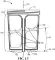
- Spray gun cup receptacles according to the present disclosure can also permit increased visibility of the contents of the spray gun cup through their sidewall, due to the provision of apertures therein. This can be particularly beneficial during paint mixing, when the painter may wish to view the levels of the various liquids added to the spray gun cup to ensure the proper volumes and/or ratios of components are used. Because the apertures cannot become coated with paint, the contents of the spray gun cup can continue to be easily viewed even if the remainder of the sidewalls become coated with paint.
- the brace member leaves a sufficient portion of the apertures non-occluded, such that the contents of the spray gun cup are visible at every height at from at least one viewing direction.
- the painter need only rotate the spray gun cup - or view the spray gun cup from another direction - until that height becomes visible. In this way, the painter can determine the precise liquid level of contents at any height, regardless of the opacity of the spray gun cup receptacle.
- a spray gun cup receptacle can provide strength, rigidity, and structure during paint mixing.
- the spray gun cup receptacle is left in place while spraying.
- the spray gun cup receptacle can also provide strength, rigidity, and structure when connecting the spray gun cup to a spray gun, and in the painting processes itself.
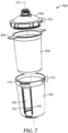
- a spray gun cup may include a liner that can be inserted into the spray gun cup receptacle.
- the spray gun cup receptacle may serve as an outer support cup.
- a spray gun cup may comprise a lid member that may optionally include an integrated filter.
- An integrated filter can eliminate the need for a separate filter by allowing a user to mix the paint within the paint cup itself (i.e., there is no need to transfer paint from another receptacle). Because the number of transfer steps is reduced, the amount of paint wasted is reduced. Examples of lid members and liners suitable for use in some embodiments of the present disclosure can be found in PCT Publication WO 1998/032539 to Joseph et al. (alternatively US Publication US 2004/0256484 A1 ).
- Spray gun cups and spray gun cup receptacles can provide the necessary structure to withstand all typical forces in the use of the paint spray system.
- the receptacle, the liner, or the mix ratio gauge may be rotated or otherwise adjusted to reveal any portion of the contents that was previously concealed by the spray gun cup receptacle. Visibility of the contents, while maintaining sufficient strength, rigidity, and structure as required throughout the mixing, connecting, and painting processes, are thus ensured.
- Spray gun cups, receptacles, lids, and liners according to the present disclosure can further ease the assembly, use, disassembly, and cleanup compared to known systems.
- the lid is able to connect directly to the receptacle without the need of an independent collar, and complementary connection features are provided on the lid and receptacle to assist in part alignment while at the same time speeding connection and reducing mistakes.
- embodiments according to the present disclosure can assist users in separating a liner from a lid to which the liner is securely sealed.
- the features disclosed herein can provide this functionality while also reducing the likelihood of rupturing the liner and/or causing paint spills.
- some embodiments can provide improved tactile feedback to a user who is gripping an apertured receptacle to guide the user to avoid improperly pinching or squeezing a liner that is filled with paint, thus reducing the likelihood of costly spills.
- brace member 160 angle ⁇ may be chosen as any angle greater than 0 degrees and less than 90 degrees (i.e., the brace member 160 is neither parallel nor orthogonal to the base end plane 134) that both facilitates the structural requirements of the spray gun cup receptacle 100 and also provides visibility as described herein at all levels of the cavity 120 through at least one aperture.
- a brace member 160 should divide at least two apertures 150 such that the apertures 150 are positioned - at least partially - vertically one over the other, and thus brace member 160 angles ⁇ much less than 90 degrees (e.g., 30 degrees or less) are expected for most spray gun cup receptacle 100 sizes and geometries.
- apertures 150 are divided by brace members disposed at brace member 160 angles ⁇ such that an upper aperture is positioned higher than a lower aperture, thereby permitting visibility at all liquid levels.
- the trajectory "T” need not be strictly elliptical in order to fall within the scope of the present disclosure.
- the spray gun cup receptacle 100 may be formed as generally cylindrical, but with a slight draft angle (e.g., approximately 3 degrees) such that its profile increases from the base end 130 to the open end 110, resulting in a trajectory "T” along the brace member 160 angle ⁇ that is generally elliptical, but in reality is slightly “egg-shaped.”
- the brace member 160 may follow a differing trajectory or trajectories.
- FIGS. 2 and 3 depict alternative variants of spray gun cup 500 receptacles comprising more than one brace member 160 disposed in a manner different from the variants of FIGS. 1A-1D .
- a brace member 160 could be provided to follow a trajectory whose brace member 160 angle ⁇ varies as its position about the sidewall 140 varies - e.g., a sinusoidal wave, a square wave, or a sawtooth pattern. Such waves or patterns could be repeating or irregular.
- the variants of spray gun cup 500 receptacles depicted herein all show a generally circular cross-section, this need not be the case.
- the cross-sectional shape of the spray gun cup receptacle 100 at any given height may comprise a polygon such as a hexagon or octagon or any other shape that permits the functional purposes set forth herein to be realized.
- the brace member 160 will be shaped and disposed to enable visibility of the cavity 120 as described elsewhere herein.
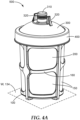
- lid member 300 captures the lid member 300 and the liner 200 between the collar 400 and the spray gun cup receptacle 100 via collar connection structure 470 - in this case screw threads.
- collar connection structure 470 in this case screw threads.
- Any of the receptacle connection structures 170 earlier described may be used in similar fashion to permit an optional collar 400 to attach to the remainder of the spray gun cup 500.
- the lid member 300 itself can be provided with lid connection structure 370 to compliment the collar connection structure 470.
- the collar 400 can be configured to attach from below the lid member 300 to capture the liner 200 between the lid member 300 and the collar 400.
- the spray gun cup receptacle may remain with the spray gun cup during spraying, or the lid, liner, and collar may be detached or removed from the spray gun cup receptacle 100 as a unit during spraying (in which case the spray gun cup receptacle 100 may be primarily used as a mixing vessel only).
- the lid member 300 comprises a liquid outlet 310 and one or more outlet connection members 320 to permit the lid 300 to be connected to the liquid inlet of a spray gun.
- An outlet connection member 320 may be provided on, about, adjacent, or remote from, the liquid outlet 310 so long as it facilitates secure, liquid-tight connection to a spray gun.
- the lid comprises a filter (not shown) to permit the liquid in the spray gun cup to be filtered prior to spraying.
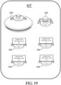
- the liquid outlet 310 and/or outlet connection member(s) 320 may be formed integrally with the remainder of the lid 300. Alternatively, these components may be initially formed as a separate, modular part or assembly comprising connection geometry to permit connection to the remainder of the lid 300. Example of such a configurations are depicted in FIGS. 17-18A , which each depict exemplary lid 300 comprising a modular lid base 304 and a modular liquid outlet 330 connected thereto.
- FIG. 17A and 18A depict the assemblies of FIGS. 17 and 18 , respectively, in a disassembled state, while FIG.
- a modular lid base 304 as a kit provided with a plurality of modular liquid outlets 330 configured to fit a variety of spray guns (in this case the alternate spray guns are labeled "B,” "C,” “D,” “E,” etc.).
- spray guns in this case the alternate spray guns are labeled "B,” "C,” “D,” “E,” etc.
- a common modular lid base 304 can be manufactured in a single (likely larger) tool, while the smaller modular liquid outlets 330 - which presumably would be manufactured at a lower volume - can be manufactured on smaller, less expensive tooling and equipment.
- changes in the connection geometry to a particular spray gun, or the introduction of new spray guns can be accommodated without the need to modify of the tooling for the modular lid base.
- outlet connection members 320 useful for lids 300 described herein include, for example, those shown and described in US Application No. 15/375,556 (3M Docket No. 78953US002 entitled " Reservoir systems for hand-held spray guns and methods of use"), and in US Provisional Application Nos. 62/322,492 , 62/279,619 and 62/279,537 (respective 3M Docket Nos.
- a modular liquid outlet 330 provided as above could alternatively be attached or preassembled to the end of a paint supply line or pouch etc. and in turn connected to the spray gun pain t inlet. In this way, paint could be directly to the spray gun without the need for the modular lid base 304, the liner 200, or the spray gun cup receptacle 100.
- Constructing the lid 300 using a modular liquid outlet 330 and a modular lid base 304 can provide a further advantage or allowing more complex geometries to be feasibly created than may otherwise be possible using, e.g., injection molding.
- injection molding e.g., injection molding
- tooling can be designed to directly access surfaces of each modular component that would not have been accessible on the one-piece lid.
- further geometric complexity can be achieved.
- Modular lid components may also be constructed of different materials as desirable for the application. For example, it may be desirable to use an engineering plastic for the modular liquid outlet 330 (due the strength and tolerances required for a secure and durable connection to the spray gun), while lower cost polymers could be used for the modular lid base 304.
- a modular liquid outlet 330 could be secured to the modular lid base 304 (or vice versa) in a variety of ways. For example, spin welding, sonic welding, quarter turn locking, other mechanical locking mechanisms, glues/adhesives, threaded, other mechanical fasteners i.e. screws, rivets and/or molded posts that are cold formed/hot formed and mushroomed down to hold/retain the component(s) in place and provide a suitable leak-proof seal.
- the modular liquid outlet 330 is located against and secured to the modular lid base 304 with the aid of a sealing feature 306 and an alignment feature 309.
- the sealing feature 306 is on the modular lid base 304 and comprises a cylindrical protrusion 307 comprising a one or a plurality of radial sealing ribs 308 adapted to interact with an interior surface 311 of liquid outlet 310 to create a liquid-tight seal upon assembly of the modular liquid outlet 330 to the modular lid base 304.
- the alignment features 309 assist to locate the two parts together and also to resist relative rotation of the parts once assembled.
- the two parts may be additionally secured by an adhesive, welding, or the like after assembly, if desired.
- the fit between the modular liquid outlet 330 and the modular lid base 304 may be constructed to be sufficiently secure without the aid of further fasteners (e.g., by way of a friction fit, snap-fit, thread, or the like). Sealing features 306 and/or alignment features 309, where used, may be interchanged between the two parts as appropriate.
- the modular liquid outlet 330 is secured to the modular lid base 304 by way of welding and/or an adhesive or the like.
- the adhesive joint and/or weld joint act to both retain and create a liquid-tight seal upon assembly of the modular liquid outlet 330 to the modular lid base 304.
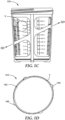
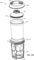
- FIG. 4C depicts an exploded view of a spray gun cup 500 including volumetric indicia provided on an insert 600.
- the insert 600 may comprise a sheet that is deformable to the cavity of the spray gun cup receptacle upon insertion.
- an insert 600 could be provided as a pre-molded unit that could drop into the spray gun cup receptacle 100 without deformation.
- An insert 600 may be constructed such that the insert 600 is registered in the cavity and with respect to the apertures and thus generally fixed against rotation.
- the insert 600 may be provided as described above with repeating volumetric indicia "V" such that each liquid level is visible from at least one position about the spray gun cup receptacle.
- the insert 600 may be registerable in more than one location such that the insert can be inserted and fixed in more than one position.
- FIG. 4D depicts an exploded view of a spray gun cup 500 not including volumetric indicia V, but wherein the contents of the cavity are nonetheless visible at all fluid levels through at least one aperture as described elsewhere herein.
- the liner is generally constructed from a transparent or translucent material.
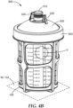
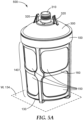
- FIG. 5A depicts a spray gun cup 500 different from the one depicted in FIG. 4A in that no collar 400 is used. Rather, the lid member 300 is adapted to be secured without the need of a collar.
- the lid member 300 may be provided with lid connection structure 370 that may have alternatively been provided on a collar 400.
- the lid member 300 may itself screw directly (via lid connection structure 370) into - or on to, or both - the spray gun cup receptacle 100.
- the lid member 300 could comprise lid connection structure 370 to compliment receptacle connection structure 170 as previously discussed with respect to FIG. 1A (e.g., a snap-fit connection, a push-fit connection, a twist-lock connection, a clip connection, a latch connection, a hinged connection, or combinations thereof).
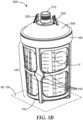
- FIG. 5B depicts a variant as in FIG. 5A further including volumetric indicia V as described elsewhere herein.
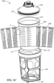
- FIG. 5C depicts an exploded view of a spray gun cup 500 including volumetric indicia provided on an insert 600.
- the insert 600 may comprise a sheet that is deformable to the cavity of the spray gun cup receptacle 100 upon insertion.
- an insert 600 could be provided as a pre-molded unit that could drop into the spray gun cup receptacle 100 without deformation.
- FIG. 5D depicts an exploded view of a spray gun cup 500 not including volumetric indicia, but wherein the contents of the cavity are nonetheless visible at all fluid levels through at least one aperture as described elsewhere herein.
- the lid connection structure 370 comprises a snap-fit connection with complimentary receptacle connection structure 170.
- the liner is generally constructed from a transparent or translucent material.
- FIGS. 6 through 8 depict embodiments of a spray gun cup 500 that, like the variants of FIGS. 5A-5D , have a lid 300 connected directly to the receptacle connection structure 170 without the need of a separate collar 400.
- An exemplary liner for use with such a spray gun cup 500 is shown in FIGS. 9-9A
- an exemplary spray gun cup receptacle is shown in FIGS. 10-10A
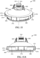
- various exemplary embodiments of lids 300 are depicted in FIGS. 11-16B .
- the spray gun cup receptacle 100 comprises one or more apertures 150.
- apertures 150 could be provided in the manner described above (i.e., intersected by one or more brace members), no brace members are shown here.
- a tactile feedback member 152 may be provided as a recess in the outer wall 104, or, e.g., as a texture on the outer wall 104.
- the tactile feedback member(s) allow a user to know, without looking at the spray gun cup 500, that they are gripping an area adjacent an aperture, such that they can properly locate their hand(s) and avoid inadvertently applying excess pressure (such as by squeezing) to the liner 200 through the aperture(s). It has been found that squeezing the liner 200 when it is filled with paint can cause spilling of paint (by forcing paint upward an out of the open end 210 of the liner 200 or accidental disconnection of the lid 300 from the liner 200 through excess deformation of the open end 210 of the liner 200.
- FIGS. 6-16B comprise a different configuration of aperture as compared to FIGS. 1-5D
- any of the lids 300 and spray gun cup receptacles 100 described herein could be used with one another provided any necessary modifications are made to the respective receptacle, lid, and/or optional collar connection structures (170, 370, 470, respectively).
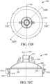
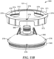
- FIGS. 11-16B depict various exemplary embodiments of lids useful with spray gun cup 500 receptacles described herein.
- the lid 300 may comprise one or more liner sealing members 340.
- a liner sealing member 340 when provided, functions as follows: a liner 200 is inserted into the open end 110 of a spray gun cup receptacle 100; paint is added through the open end 110 of the liner 200; a lid 300 it positioned in the open end 110 of the liner 200 (and receptacle); the lid 300 is secured to the receptacle in a direction along the central axis 101 such that the open end 110 of the liner 200 is stretched radially over the liner sealing member 340 and finally into full sealing engagement.
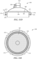
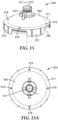
- a liner sealing member 340 may comprise one or more radially-outwardly protruding features, such as those shown in FIGS. 11-11E and 15-19 .
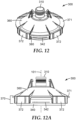
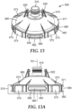
- a liner sealing member may additionally (or alternatively) comprise a chamfered or otherwise tapered surface, such as those shown in FIGS. 12-14A .
- the lid 300 may further comprise a liner seal catch 342, an example of which is most clearly depicted in FIGS. 12-13A .
- a liner seal catch 342 can enhance liner retention on the lid 340 and, some embodiments can assist in providing tactile and/or audible reassurance to the end user that the lid 300 is securely seated in the liner 200 by permitting a "snapping" action as discussed in more detail elsewhere in this specification.
- a liner seal catch 342 is particularly suited for use in conjunction with a chamfered or otherwise tapered liner sealing member 340 as described above because such a tapered surface may lack other features that could assist in resisting against the liner 200 being pulled away from the lid (e.g., the radially-outwardly protruding features shown with the liner sealing member 340 in FIGS. 11-11E and 15-19 ). However, a liner seal catch 342 may be employed as additional support even in those constructions.
- the entire spray gun cup 500 may be discarded after use, users may wish to remove the liner 200 from the lid 300 either to add additional paint or to replace the lid 300 with a fresh one (e.g., when a filter 301 in the lid 300 has become clogged or when paint has dried thereon).
- a liner 200 can be difficult to remove from the lid 300 without damaging the liner 200 or spilling paint. Therefore, the liner 200 may be provided with one or more release tabs 204 that facilitate easy removal of the liner 200 from the lid 300 after assembly. These release tabs 204 are depicted in greater detail in FIGS. 7 , 9 , and 9A .
- FIG. 8 depicts an embodiment wherein the liner 200 optionally does not comprise release tabs 204.
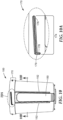
- the lid 300 may comprise a lid body 360 and be provided with a flange 371 about its periphery.
- the flange 371 carries at least a portion of the lid connection structure 370, and in particular the lid engagement member(s) 372.
- one or more flange openings 380 are provided such that the flange 371 is interrupted about its periphery.
- the flange opening(s) 380 can allow clearance for the release tab(s) 204 on the liner 200 to extend from the spray gun cup 500 for convenient gripping and lifting of the liner 200. As shown, the flange opening(s) 380 penetrate the lid connection structure 370.
- an inclined or curved surface portion may be provided on the complementary lid camming surface 376 (described in greater detail elsewhere) such that a camming action is facilitated when the parts interact.
- the camming surface 176 it is adapted interact with complementary structure on the lid 300 to permit the lid 300 to be securely attached to the spray gun cup receptacle 100 such that the liner 200 is retained in sealing relation between the lid 300 and the receptacle.
- the "snapping" sensation and/or sound derives from a combination of: (i) the liner sealing member(s) 340 being quickly advanced into the open end 210 of the liner 200 such that a portion of the liner 200 rapidly stretches over the liner sealing member 340 and then relaxes; and (ii) the lid rim 312 accordingly impacting the liner rim 212 / receptacle rim 112 as the lid 300 quickly drops into contact.
- This brief snapping sensation can provide tactile and/or audible reassurance to the end user that the lid 300 and liner 200 are securely attached, although the lid has yet to be secured to the spray gun cup receptacle 100.
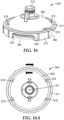
- the lid comprises four flange tabs 372 - one corresponding to each receptacle engagement member 174.
- the flange tabs 372 may be provided as independent members protruding along the central axis 101 from a radially-outer periphery of the lid 300, as shown for example in FIGS. 11-12E and 15-16B .
- flange tabs 372 may be connected by flange bridging members 382.
- flange openings 380 may be provided in the area(s) between flange tabs 372.
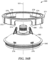
- the flange 371 may be retained on the lid 300 via one or more flange retention features 378. Exemplary embodiments comprising flange retention features 378 are shown in FIGS. 15 -16B .
- the flange 371 is rotationally fixed relative to the lid 300.
- the flange 371 is permitted to rotate relative to the lid 300. In some embodiments, rotation is permitted about a full three-hundred-sixty degrees about the central axis 101, while in others rotation may be limited to a partial turn such as, for example, ninety degrees.
- a flange rotation limiting feature 377 may be provided on one or both of the lid body 360 and/or the flange 371 (see, e.g., FIGS. 16C and 16D .
- flange rotation limiting features 377 are provided on the flange 371 such that they will rotate through a predetermined arc until contact is made with a flange retention feature 378 on the lid body 360.
- a separate flange 371 may be assembled in sealing relation with respect to the lid body 360, even if the flange 371 can rotate relative to the lid body 360 (e.g., by providing a sealing gasket, etc.).
- the lid body 360 carries a liner sealing member (for example, on a skirt protruding from beneath the lid body as shown in in figures) and further comprises an inner lid body surface 361 that funnels paint to the liquid outlet.
- the lid body 361 forms a liquid conduit for the paint to flow from the liner into the spray gun such that a separate flange 371 can be movably connected to the lid body without worry of creating a leak path for paint.
- the liner 200 comprises a liner rim 212 surrounding the liner open end 210 that can provide additional sealing functionality when clamped between the lid 300 and the spray gun cup receptacle 100.
- the lid 300 may be provided with a lid rim 312 and the spray gun cup receptacle 100 with a receptacle rim 112 surrounding the open end 110.
- the camming surface 176 - through interaction with a lid camming surface 376 on lid engagement members 374 - enables a clamping force to be applied along the central axis 101 when the lid 300 is attached to the spray gun cup receptacle 100.
- one or both or the camming surface 176 and/or lid camming surface 376 is provided with geometry to cause relative clamping motion of the lid 300 and the receptacle along the central axis 101 during connection.
- such geometry may be provided - at least in part - by an inclined or curved camming surface portion as described above on either or both the camming surface 176 and/or lid camming surface 376.
Landscapes
- Nozzles (AREA)
- Closures For Containers (AREA)
- Containers And Packaging Bodies Having A Special Means To Remove Contents (AREA)
- Details Or Accessories Of Spraying Plant Or Apparatus (AREA)
Claims (14)
- Ein Spritzpistolenbecherdeckel (300), aufweisendeinen Deckelkörper (360), der einen Flüssigkeitsauslass (310) aufweist, der sich entlang einer Mittelachse (101) des Spritzpistolendeckels (300) erstreckt; undeinen Flansch (371), der an einem Außenumfang des Deckelkörpers (360) positioniert ist, wobei der Flansch (371) eine Deckelverbindungsstruktur (370) aufweist, wobei die Deckelverbindungsstruktur (370) eine Flanschlasche (372) aufweist, die ein Deckeleingriffselement (374) aufweist,wobei der Flansch (371) eine Flanschöffnung (380) aufweist, die zwei Flanschlaschen (372) teilt,dadurch gekennzeichnet, dass die Flanschlaschen (372) entlang der Mittelachse (101) hervorstehen, und dadurch, dass der Flansch (371) als vom Deckelkörper (360) separates Teil ausgebildet ist und durch ein Flanschhaltemerkmal (378) am Deckelkörper (360) gehalten wird.
- Der Deckel nach Anspruch 1, wobei das Deckeleingriffselement (374) eine Deckelnockenoberfläche (376) aufweist, wobei optional die Deckelnockenoberfläche (376) eine geneigte Oberfläche, eine gekrümmte Oberfläche, eine flache Oberfläche oder eine Kombination davon aufweist.
- Der Deckel nach Anspruch 2, wobei der Deckelkörper (360) eine innere Deckelkörperoberfläche (361) aufweist und wobei die Deckelnockenoberfläche (376) im Allgemeinen der inneren Deckelkörperoberfläche (361) zugewandt ist.
- Der Deckel nach Anspruch 2 oder 3, wobei der Flansch (371) ein Zugangsfenster (373) aufweist, das der Flanschlasche (372) entspricht, wobei das Zugangsfenster (373) eine Öffnung bereitstellt, um Zugang zur Deckelnockenoberfläche (376) zu erlangen.
- Der Deckel nach einem der Ansprüche 1 bis 4, wobei der Flansch (371) mindestens drei Flanschlaschen (372) und mindestens drei Flanschöffnungen (380) aufweist.
- Der Deckel nach einem der Ansprüche 1 bis 5, wobei die Flanschöffnung(en) (380) einen Freiraum für eine Freigabelasche (204) einer kompatiblen Auskleidung (200) ermöglichen.
- Der Deckel nach einem der Ansprüche 1 bis 6, umfassend ein Flanschüberbrückungselement (382), das zwei Flanschlaschen (372) nahe einer Flanschöffnung (380) verbindet.
- Der Deckel nach einem der Ansprüche 1 bis 7, wobei das Deckeleingriffselement (374) ein Easy-Start-Teilgewinde aufweist, und/oder
wobei das Deckeleingriffselement (374) ein Stoppmerkmal aufweist, um eine Überdrehung des Deckels (300) beim Verbinden mit einer kompatiblen Spritzpistolen-Becheraufnahme zu verhindern. - Der Deckel nach Anspruch 1, wobei das Deckeleingriffselement (374) ein Einrastmerkmal aufweist, um zu ermöglichen, dass der Deckel (300) an einer kompatiblen Spritzpistolenbecheraufnahme einrastet.
- Der Deckel nach Anspruch 9, wobei der Flansch (371) ein Zugangsfenster (373) aufweist, das der Flanschlasche (372) entspricht, wobei das Zugangsfenster (373) eine Öffnung bereitstellt, um Zugang zum Einrastmerkmal zu erlangen.
- Der Deckel nach einem der Ansprüche 1 bis 10, wobei der Flansch (371) in Bezug auf den Deckelkörper (360) drehfest ist.
- Der Deckel nach einem der Ansprüche 1 bis 11, umfassend einen Filter (301), der positioniert ist, um eine Flüssigkeit zu filtern, bevor die Flüssigkeit aus dem Flüssigkeitsauslass (310) austritt.
- Ein Spritzpistolenbecher (100), aufweisend:
einen Deckel (300), aufweisend:einen Deckelkörper (360) mit einem Flüssigkeitsauslass (310), der sich entlang einer Mittelachse (101) des Spritzpistolenbechers (100) erstreckt; undeinen Flansch (371) an einem Außenumfang des Deckelkörpers (360), der mindestens zwei Flanschlaschen (372) aufweist, die durch eine Flanschöffnung (380) getrennt sind, wobei die Flanschlaschen (372) entlang der Mittelachse (101) hervorstehen;eine Auskleidung (200), die eine Freigabelasche (204) aufweist, wobei die Freigabelasche (204) in die Flanschöffnung (380) passt, wenn die Auskleidung (200) mit dem Deckel (300) zusammengebaut ist. - Der Spritzpistolenbecher (100) nach Anspruch 13, wobei der Deckel der Deckel (300) nach einem der Ansprüche 1 bis 12 ist.
Priority Applications (3)
| Application Number | Priority Date | Filing Date | Title |
|---|---|---|---|
| PL17701963.5T PL3402602T5 (pl) | 2016-01-15 | 2017-01-12 | Kubki, gniazda, pokrywki i sposoby stosowania pistoletu natryskowego |
| EP21156243.4A EP3851203B1 (de) | 2016-01-15 | 2017-01-12 | Verfahren zur installation eines deckels auf einem spritzpistolenbecher |
| EP23192478.8A EP4268972A3 (de) | 2016-01-15 | 2017-01-12 | Verfahren zum anbringen eines deckels auf einem spritzpistolenbehälter |
Applications Claiming Priority (2)
| Application Number | Priority Date | Filing Date | Title |
|---|---|---|---|
| US201662279292P | 2016-01-15 | 2016-01-15 | |
| PCT/US2017/013121 WO2017123709A1 (en) | 2016-01-15 | 2017-01-12 | Spray gun cups, receptacles, lids, and methods of use |
Related Child Applications (4)
| Application Number | Title | Priority Date | Filing Date |
|---|---|---|---|
| EP23192478.8A Division-Into EP4268972A3 (de) | 2016-01-15 | 2017-01-12 | Verfahren zum anbringen eines deckels auf einem spritzpistolenbehälter |
| EP23192478.8A Division EP4268972A3 (de) | 2016-01-15 | 2017-01-12 | Verfahren zum anbringen eines deckels auf einem spritzpistolenbehälter |
| EP21156243.4A Division EP3851203B1 (de) | 2016-01-15 | 2017-01-12 | Verfahren zur installation eines deckels auf einem spritzpistolenbecher |
| EP21156243.4A Division-Into EP3851203B1 (de) | 2016-01-15 | 2017-01-12 | Verfahren zur installation eines deckels auf einem spritzpistolenbecher |
Publications (3)
| Publication Number | Publication Date |
|---|---|
| EP3402602A1 EP3402602A1 (de) | 2018-11-21 |
| EP3402602B1 EP3402602B1 (de) | 2021-07-07 |
| EP3402602B2 true EP3402602B2 (de) | 2025-04-16 |
Family
ID=57910171
Family Applications (3)
| Application Number | Title | Priority Date | Filing Date |
|---|---|---|---|
| EP23192478.8A Pending EP4268972A3 (de) | 2016-01-15 | 2017-01-12 | Verfahren zum anbringen eines deckels auf einem spritzpistolenbehälter |
| EP21156243.4A Active EP3851203B1 (de) | 2016-01-15 | 2017-01-12 | Verfahren zur installation eines deckels auf einem spritzpistolenbecher |
| EP17701963.5A Active EP3402602B2 (de) | 2016-01-15 | 2017-01-12 | Spritzpistolenbecher, behälter, deckel und verfahren zur verwendung |
Family Applications Before (2)
| Application Number | Title | Priority Date | Filing Date |
|---|---|---|---|
| EP23192478.8A Pending EP4268972A3 (de) | 2016-01-15 | 2017-01-12 | Verfahren zum anbringen eines deckels auf einem spritzpistolenbehälter |
| EP21156243.4A Active EP3851203B1 (de) | 2016-01-15 | 2017-01-12 | Verfahren zur installation eines deckels auf einem spritzpistolenbecher |
Country Status (9)
| Country | Link |
|---|---|
| US (1) | US11638924B2 (de) |
| EP (3) | EP4268972A3 (de) |
| JP (2) | JP6903670B2 (de) |
| CN (1) | CN108495717B (de) |
| AU (1) | AU2017207353B2 (de) |
| CA (1) | CA3011437C (de) |
| ES (2) | ES2884258T5 (de) |
| PL (1) | PL3402602T5 (de) |
| WO (1) | WO2017123709A1 (de) |
Families Citing this family (13)
| Publication number | Priority date | Publication date | Assignee | Title |
|---|---|---|---|---|
| CN105939789B (zh) | 2013-12-05 | 2020-09-01 | 3M创新有限公司 | 用于喷涂设备的流体容器 |
| PL3402606T5 (pl) | 2016-01-15 | 2026-01-26 | 3M Innovative Properties Company | Układ złączy do ręcznych pistoletów natryskowych |
| AU2017207352B2 (en) * | 2016-01-15 | 2019-09-12 | 3M Innovative Properties Company | Spray gun cups, receptacles, and methods of use |
| WO2017123709A1 (en) | 2016-01-15 | 2017-07-20 | 3M Innovative Properties Company | Spray gun cups, receptacles, lids, and methods of use |
| EP3845313B1 (de) | 2016-01-15 | 2023-11-15 | 3M Innovative Properties Company | Weitmundiger flüssigkeitsverbinder für handspritzpistolen |
| US11040361B2 (en) | 2016-01-15 | 2021-06-22 | 3M Innovative Properties Company | Modular spray gun lid assemblies and methods of design and use |
| CN110062664B (zh) | 2016-12-12 | 2022-07-08 | 3M创新有限公司 | 用于手持式喷枪的贮存器系统 |
| EP4316777A3 (de) | 2017-07-14 | 2024-04-03 | 3M Innovative Properties Company | Flüssigkeitsabgabevorrichtung für eine spritzpistole |
| EP3902634A1 (de) | 2018-12-27 | 2021-11-03 | 3M Innovative Properties Company | Flüssigkeitsabgabeanordnung für eine sprühvorrichtung |
| USD952097S1 (en) * | 2020-07-14 | 2022-05-17 | Yuyao Yufeng Scutcheon Plastic Factory | Paint spraying pot lid |
| EP4082671A1 (de) * | 2021-04-30 | 2022-11-02 | Tai Zhou Luxi Tools Co., Ltd. | Faltbarer becher und sprühbecher |
| USD1025533S1 (en) * | 2022-03-29 | 2024-04-30 | Qingdao Hanbo Plastic Technology Co., Ltd | Paint spray for use in building |
| CN116967040A (zh) * | 2023-06-16 | 2023-10-31 | 青岛汉柏塑料科技有限公司 | 一种流体供应杯及其杯盖 |
Citations (11)
| Publication number | Priority date | Publication date | Assignee | Title |
|---|---|---|---|---|
| US1837844A (en) † | 1930-04-21 | 1931-12-22 | Binks Mfg Co | All metal sealing cap for paint containers |
| US2622770A (en) † | 1948-02-06 | 1952-12-23 | Tornado Mfg Company Inc | Connecting cap for air guns and the like |
| US3447753A (en) † | 1967-01-27 | 1969-06-03 | Jet X Corp | Spray washer with detergent feed |
| US6126048A (en) † | 1999-06-24 | 2000-10-03 | Bublitz; Todd F. | Removable paint can extension and cover |
| US6851569B2 (en) † | 2002-04-22 | 2005-02-08 | Plastican, Inc. | Reusable lid and container |
| EP1541243A1 (de) † | 2003-12-09 | 2005-06-15 | Martin Ruda | Spritzpistolenbecher mit einer verriegelbaren Anschlusseinrichtung |
| US20070131793A1 (en) † | 2001-04-24 | 2007-06-14 | 3M Innovative Properties Company | Reservoir with refill inlet for hand-held spray guns |
| US7380680B2 (en) † | 2004-01-16 | 2008-06-03 | Illinois Tool Works Inc. | Fluid supply assembly |
| US20090078790A1 (en) † | 2003-08-26 | 2009-03-26 | Michel Camilleri | Disposable cup to be set up on a spray gun for preparing, applying and preserving a paint |
| ES1121280U (es) † | 2014-08-05 | 2014-09-03 | Bossauto Innova, S.A. | Disposición para cartucho flexible para pistola pulverizadora de pintura |
| WO2015109409A1 (en) † | 2014-01-23 | 2015-07-30 | Abdiye Abbey | Lid for beverage containers |
Family Cites Families (139)
| Publication number | Priority date | Publication date | Assignee | Title |
|---|---|---|---|---|
| US1395965A (en) | 1919-08-13 | 1921-11-01 | Edward J Mclean | Atomizing and spraying device |
| US1732691A (en) | 1927-04-28 | 1929-10-22 | Vilbiss Co | Spray head |
| US1968173A (en) | 1932-11-28 | 1934-07-31 | Russell Matthew | Spraying device |
| US2004574A (en) | 1933-02-13 | 1935-06-11 | Jr William Oliver Gee | Spray gun reservoir |
| US2037240A (en) | 1933-09-25 | 1936-04-14 | Johnson Swan | Clutch device adapted for spray guns |
| US3083883A (en) | 1960-03-30 | 1963-04-02 | Robert T Glidden | Container for spray appliance |
| GB1066861A (en) | 1963-02-22 | 1967-04-26 | Carr Fastener Co Ltd | Clip for fastening together two apertured panels |
| US3401842A (en) | 1966-11-28 | 1968-09-17 | Betty L Morrison | Combination paint cup and filler for spray guns |
| JPS4814196B1 (de) | 1969-05-06 | 1973-05-04 | ||
| JPS4814196Y1 (de) * | 1970-06-04 | 1973-04-18 | ||
| US3942680A (en) | 1973-07-31 | 1976-03-09 | Seeley Larry E | Spray paint container and attachment therefor |
| JPS5337897Y2 (de) * | 1974-07-04 | 1978-09-13 | ||
| JPS5110078A (de) | 1974-07-09 | 1976-01-27 | Mitsubishi Corp | |
| USD252156S (en) | 1975-09-18 | 1979-06-19 | Lucas Industries Limited | Diaphragm |
| US4430084A (en) | 1980-01-21 | 1984-02-07 | American Hospital Supply Corp. | Method for pre-use storage of a medical receptacle |
| JPS6027748B2 (ja) | 1981-04-30 | 1985-07-01 | 株式会社佐藤製作所 | 焼結機パレットのサイドウォ−ル用材料 |
| JPS629966Y2 (de) * | 1981-05-08 | 1987-03-09 | ||
| FR2521957B1 (fr) * | 1982-02-23 | 1986-10-31 | Wassilieff Victor | Fermeture des recipients, munie d'une paroi flexible convergeant vers le bas; et ses applications |
| FR2620424B1 (fr) | 1987-09-15 | 1989-12-15 | Morel Simone | Conteneur a capuchon amovible a generatrices laterales alignees |
| USD315781S (en) | 1988-12-28 | 1991-03-26 | E. I. Du Pont De Nemours And Company | Attachment for paint container |
| DE8902223U1 (de) | 1989-02-24 | 1989-04-06 | SATA - Farbspritztechnik GmbH & Co., 7140 Ludwigsburg | Farbspritzpistole |
| US5150804A (en) | 1991-03-14 | 1992-09-29 | Oscar Blanchet | Rotationally resistive pail, pail support and coupling for cementatious or viscous materials |
| US5240133A (en) | 1991-04-15 | 1993-08-31 | James River Paper Company, Inc. | Clamped-wave lid seal structure |
| US5226551A (en) | 1991-11-12 | 1993-07-13 | Robbins Edward S Iii | Reusable and re-collapsible container |
| JPH08505345A (ja) * | 1993-01-21 | 1996-06-11 | エス.ザ・サード ロビンス,エドワード | 再利用が可能で再度縮退状態にできる容器および関連キャップ |
| GB2298194A (en) | 1995-02-24 | 1996-08-28 | Beeson & Sons Ltd | Child resistant closures for containers |
| JP3052058B2 (ja) | 1996-03-19 | 2000-06-12 | 株式会社ケーヒン | エンジンのスロットル弁駆動装置 |
| JPH09276758A (ja) * | 1996-04-12 | 1997-10-28 | Canyon Corp | ポンプディスペンサ−装着方法、ポンプディスペンサ−、容器蓋装着方法および容器蓋 |
| US5816501A (en) | 1996-12-16 | 1998-10-06 | Ransburg Corporation | Disposable paint container liner and method |
| CN1142830C (zh) | 1997-01-24 | 2004-03-24 | 美国3M公司 | 喷洒液体用的喷枪 |
| US6820824B1 (en) | 1998-01-14 | 2004-11-23 | 3M Innovative Properties Company | Apparatus for spraying liquids, disposable containers and liners suitable for use therewith |
| JP3052058U (ja) * | 1998-03-06 | 1998-09-11 | 株式会社ヨトリヤマ | 塗料吸上げ式スプレー塗装機の塗料容器 |
| US6435426B1 (en) | 1999-05-11 | 2002-08-20 | William H. Copp, Jr. | Floating gasket plate for paint cup on spray gun |
| DE29909950U1 (de) | 1999-06-08 | 1999-09-23 | Chang, Jen-Chih, Taichung | Spritzpistolenbehälter |
| US6375031B1 (en) | 1999-07-26 | 2002-04-23 | Merry Chance Industries, Ltd. | Container for liquids having viewing window |
| US6536687B1 (en) | 1999-08-16 | 2003-03-25 | 3M Innovative Properties Company | Mixing cup adapting assembly |
| GB0110025D0 (en) | 2001-04-24 | 2001-06-13 | 3M Innovative Properties Co | Improvements in or relating to liquid spraying apparatus |
| US6588681B2 (en) | 2001-07-09 | 2003-07-08 | 3M Innovative Properties Company | Liquid supply assembly |
| DE10295453D2 (de) | 2001-11-14 | 2004-10-14 | Martin Ruda | Spritzpistolenbecher mit fester Einlage |
| US6547161B1 (en) | 2001-12-18 | 2003-04-15 | Tiao-Hsiang Huang | Spray paint gun head |
| AUPR991202A0 (en) | 2002-01-10 | 2002-01-31 | Owens-Illinois Closure Inc. | A self-venting sports type closure |
| DE20202123U1 (de) | 2002-02-13 | 2003-02-06 | SATA Farbspritztechnik GmbH & Co.KG, 70806 Kornwestheim | Farbspritzpistole |
| US6662411B2 (en) | 2002-03-04 | 2003-12-16 | Hewlett-Packard Development Company, L.P. | Mushroom head clip fastener |
| US6752179B1 (en) | 2002-03-28 | 2004-06-22 | 3M Innovative Properties Company | Small liquid supply assembly |
| US6739781B2 (en) | 2002-04-22 | 2004-05-25 | Seaquist Closures Foreign, Inc. | Scrubbing structure |
| GB0210448D0 (en) | 2002-05-08 | 2002-06-12 | 3M Innovative Properties Co | Valve closure for spray gun reservoir |
| USD474528S1 (en) | 2002-10-17 | 2003-05-13 | Tiao-Hsiang Huang | Spray gun |
| US6953155B2 (en) * | 2002-10-24 | 2005-10-11 | 3M Innovative Properties Company | Pressure assisted liquid supply assembly |
| GB0224698D0 (en) * | 2002-10-24 | 2002-12-04 | 3M Innovative Properties Co | Easy clean spray gun |
| EP1587631B1 (de) | 2002-12-10 | 2007-05-09 | Martin Ruda | Einwandiger spritzpistolenbecher und verfahren zum herstellen eines deckels |
| DE10315426A1 (de) | 2002-12-10 | 2004-06-24 | Martin Ruda | Spritzpistolenbecher und Verfahren zum Herstellen eines Deckels |
| US6945429B2 (en) | 2003-06-10 | 2005-09-20 | Illinois Tool Works Inc. | Disposable paint cup attachment system for gravity-feed paint sprayer |
| US7080750B2 (en) | 2003-09-12 | 2006-07-25 | Ruaw, Iwc | Packing and waste disposal system |
| US7083119B2 (en) | 2003-09-25 | 2006-08-01 | 3M Innovative Properties Company | Security clip for spray gun connector |
| CA2448110A1 (en) | 2003-11-05 | 2005-05-05 | Simon Yechouron | Paint gun accessory |
| ITTO20030981A1 (it) | 2003-12-05 | 2005-06-06 | Anest Iwata Europ S R L | Pistola manuale a spruzzo e relativa tazza. |
| US7032839B2 (en) | 2003-12-30 | 2006-04-25 | 3M Innovative Properties Company | Liquid spray gun with manually separable portions |
| US7086549B2 (en) * | 2004-01-16 | 2006-08-08 | Illinois Tool Works Inc. | Fluid supply assembly |
| US7165732B2 (en) | 2004-01-16 | 2007-01-23 | Illinois Tool Works Inc. | Adapter assembly for a fluid supply assembly |
| DE202004021702U1 (de) | 2004-01-22 | 2010-05-20 | Sata Gmbh & Co. Kg | Fließbecher für eine Farbspritzpistole |
| DE102004003439B4 (de) | 2004-01-22 | 2022-02-03 | Sata Gmbh & Co. Kg | Farbbechersystem für eine Farbspritzpistole |
| DE202004003116U1 (de) | 2004-02-28 | 2005-07-14 | Sata Farbspritztechnik Gmbh & Co.Kg | Fließbecher für eine Farbspritzpistole |
| EP1604701B1 (de) | 2004-06-09 | 2010-12-15 | Microflow Engineering SA | Verbessertes modulares Flüssigkeitssprühsystem |
| ATE340033T1 (de) | 2004-07-02 | 2006-10-15 | Flexi Cup | Flexibler farbbehälter |
| NL1027170C2 (nl) | 2004-09-14 | 2006-03-15 | Bolk Techniek | Wasinrichting. |
| US7353973B2 (en) | 2004-11-15 | 2008-04-08 | Rieke Corporation | Seal retainer for use in liquid-storage containers |
| DK1835997T3 (da) * | 2004-12-16 | 2012-09-24 | Saint Gobain Abrasives Inc | Væskeforsyningsskål og inderbeholderanordning til sprøjtepistoler |
| US7175110B2 (en) * | 2004-12-21 | 2007-02-13 | Anest Iwata Corporation | Manual spray gun and associated disposable cup |
| US7410106B2 (en) | 2005-02-08 | 2008-08-12 | 3M Innovative Properties Company | Pressurized liquid supply assembly |
| US7429143B2 (en) | 2005-05-04 | 2008-09-30 | Wlodzimierz M Tyski | Detachable fastening system |
| US7036752B1 (en) | 2005-06-20 | 2006-05-02 | Shin Kuei Hsiang | Connection of cup and paint sprayer |
| US20070095943A1 (en) | 2005-10-28 | 2007-05-03 | Turnbull William N | Liquid reservoir, and kit, spray assembly and method using same |
| USD542376S1 (en) | 2005-11-30 | 2007-05-08 | 3M Innovative Properties Company | Spray gun nozzle and air cap assembly |
| US20070158361A1 (en) | 2005-12-30 | 2007-07-12 | Yasuhiro Koyama | Liquid supply assembly and liquid spray apparatus |
| PL2029285T3 (pl) | 2006-06-20 | 2013-04-30 | Saint Gobain Abrasives Inc | Zespół doprowadzający ciecz |
| EP2000218A1 (de) | 2007-06-07 | 2008-12-10 | S.A. Omniform | Selbsttätiges Lüftungsventil für einen Farbversorgungsbehälter |
| NL1033999C2 (nl) | 2007-06-18 | 2008-12-22 | Emm Productions B V | Deksel voor een spuitbeker, werkwijze voor het vrijgeven van een balg in een spuitbeker en een flens voor plaatsing tussen een spuitbeker en een deksel. |
| MX2010000479A (es) | 2007-07-13 | 2010-06-23 | Seaquist Closures Loeffler Gmbh | Sistema de cierre para un envase y cierre dispensador. |
| DE102007039106B4 (de) | 2007-08-18 | 2022-06-09 | Sata Gmbh & Co. Kg | Farbbehälter für eine Spritzpistole, mit einem Anschlussteil zur Verbindung des Farbbehälters an eine Spritzpistole und Farbspritzeinrichtung |
| DE102007048440B3 (de) | 2007-10-02 | 2009-04-16 | G-Mate Ag | Deckel für Mischbecher von Farbspritzpistolen |
| USD574926S1 (en) | 2007-11-30 | 2008-08-12 | Kuan Chang Co., Ltd | Paint cup for a spray gun |
| WO2009090273A1 (es) | 2008-01-16 | 2009-07-23 | Boss Auto Import, S.A. | Copa desechable de doble pared con superficie interior flexible y su tapa perfeccionadas para pistolas aerográficas |
| WO2009143148A1 (en) | 2008-05-19 | 2009-11-26 | Meadwestvaco Corporation | Pump retention collar and methods for using the same |
| USD616961S1 (en) | 2008-09-29 | 2010-06-01 | Robert Bosch Gmbh | Jet cleaner for a water sprinkler |
| DE202008014389U1 (de) | 2008-10-29 | 2010-04-08 | Sata Gmbh & Co. Kg | Fließbecher für eine Farbspritzpistole |
| US8066205B2 (en) | 2008-12-30 | 2011-11-29 | Campbell Hausfeld/Scott Fetzer Company | Pressure-siphon switch for pneumatic spray gun |
| ES2620017T3 (es) | 2009-01-26 | 2017-06-27 | 3M Innovative Properties Company | Pistola pulverizadora de líquido, plataforma de pistola pulverizadora y unidad de cabezal de pulverización |
| USD607807S1 (en) | 2009-05-18 | 2010-01-12 | Ohlhorst Gary R | Cup holder and covered storage bin for scooters |
| DE102009034715A1 (de) | 2009-07-24 | 2011-01-27 | Martin Ruda | Spritzgusswerkzeug, Verfahren zum Spritzgießen eines Spritzgussbauteils sowie Verschluss- und/oder Anschlusseinrichtung eines Spritzpistolenfarbbechers |
| WO2011021998A1 (en) | 2009-08-18 | 2011-02-24 | Louis M. Gerson Co., Inc. | Strainer with dispensing tab and dispenser for same |
| USD656583S1 (en) | 2009-10-08 | 2012-03-27 | H.D. Hudson Manufacturing Company | Sprayer |
| DE202010009104U1 (de) | 2009-10-23 | 2011-03-10 | Sata Gmbh & Co. Kg | Farbbehälter, insbesondere für Farbspritzpistolen |
| CA135323S (en) | 2009-11-10 | 2011-07-12 | Suntory Holdings Ltd | Case for holding natural or artificial plants |
| CN201702069U (zh) | 2010-02-11 | 2011-01-12 | 潘星钢 | 一种用于喷漆枪的流体储存器 |
| USD642863S1 (en) | 2010-03-24 | 2011-08-09 | Earthkare Packaging Innovations Company | Cup with an integral lid |
| CN101856639A (zh) * | 2010-06-22 | 2010-10-13 | 上海法固电子科技有限公司 | 一种用于喷漆枪的漆壶 |
| US20120000992A1 (en) | 2010-07-01 | 2012-01-05 | Hsien-Chao Shih | Paint cup structure of paintball gun |
| US10286414B2 (en) | 2010-07-12 | 2019-05-14 | Carlisle Fluid Technologies, Inc. | Liquid supply container for a spray coating device |
| GB2484064B (en) | 2010-08-26 | 2016-01-06 | Rotite Ltd | Connector and method of connecting two items together |
| USD689735S1 (en) | 2010-10-22 | 2013-09-17 | Tracy Redfern | Hot beverage cup lid |
| WO2012068316A2 (en) | 2010-11-16 | 2012-05-24 | Saint-Gobain Abrasives, Inc. | Liquid supply assembly with an improved liner |
| DE202011100181U1 (de) | 2011-05-03 | 2012-08-06 | Geka Gmbh | Applikatorschnellverschluss |
| MX346790B (es) | 2011-05-06 | 2017-03-31 | Saint Gobain Abrasifs Sa | Montaje de depósito de pintura con múltiples sellos. |
| CA2835088C (en) | 2011-05-06 | 2018-01-16 | Saint-Gobain Abrasives, Inc. | Paint cup assembly with an extended ring |
| WO2013003592A2 (en) | 2011-06-30 | 2013-01-03 | Saint-Gobain Abrasives, Inc. | Paint cup assembly |
| USD679146S1 (en) | 2011-09-13 | 2013-04-02 | Alfonso J. Rincon | Cup holder with pressure clip |
| EP2771127B1 (de) | 2011-10-27 | 2017-07-12 | Graco Minnesota Inc. | Zerstäuberflüssigkeitszufuhr mit faltbarem innenfutter |
| US8844840B2 (en) | 2011-12-20 | 2014-09-30 | Campbell Hausfeld/Scott Fetzer Company | Paint sprayer with paint container attachment apparatus |
| USD689593S1 (en) | 2012-01-27 | 2013-09-10 | Sata Gmbh & Co. Kg | Spray gun |
| USD719637S1 (en) | 2012-02-21 | 2014-12-16 | Ferro Pagliai | Lid for a backpack sprayer |
| USD692530S1 (en) | 2012-07-04 | 2013-10-29 | Sata Gmbh & Co. Kg | Paint spray gun cup |
| US9227208B2 (en) | 2012-10-15 | 2016-01-05 | Chin-Hsin Lin | Paint cup for spray gun |
| US9352343B2 (en) | 2013-01-22 | 2016-05-31 | Carlisle Fluid Technologies, Inc. | Liquid supply system for a gravity feed spray device |
| WO2014160922A1 (en) | 2013-03-29 | 2014-10-02 | 3M Innovative Properties Company | Vented container assembly |
| WO2014182722A1 (en) | 2013-05-06 | 2014-11-13 | Heyn William M | Heat sealing on multiple angled container flanges |
| TW201505715A (zh) | 2013-05-08 | 2015-02-16 | Graco Minnesota Inc | 用於手持噴灑裝置之塗料罐轉接器 |
| US9038674B2 (en) | 2013-06-14 | 2015-05-26 | Sps Lid Technology Ii, Llc | Paint can cover assembly with paint return port |
| USD705899S1 (en) | 2013-07-23 | 2014-05-27 | The Fountainhead Group, Inc. | Shroud for a manually operated spray tank |
| US20150108135A1 (en) * | 2013-10-17 | 2015-04-23 | Fadi Hanna | Disposable components for a spray gun |
| CN105939789B (zh) * | 2013-12-05 | 2020-09-01 | 3M创新有限公司 | 用于喷涂设备的流体容器 |
| USD739242S1 (en) | 2013-12-16 | 2015-09-22 | 3M Innovative Properties Company | Container for disposable spray gun components |
| USD747497S1 (en) | 2014-04-21 | 2016-01-12 | First Wave Products Group, Llc | Pill crushing cup lid |
| USD758533S1 (en) | 2014-06-02 | 2016-06-07 | Sata Gmbh & Co. Kg | Paint spray gun cup |
| USD755345S1 (en) | 2014-08-06 | 2016-05-03 | Gema Switzerland Gmbh | Filter component |
| USD755575S1 (en) | 2014-09-08 | 2016-05-10 | Railblaza Limited | Cup holder |
| WO2016081977A1 (en) | 2014-11-28 | 2016-06-02 | Kambouris Shares Pty Ltd | A separable container for housing and dispensing beverages under pressure |
| CN204710607U (zh) | 2015-05-04 | 2015-10-21 | 胡家豪 | 用于喷漆枪上的快速喷壶 |
| CN107847956B (zh) | 2015-07-08 | 2021-08-10 | 3M创新有限公司 | 喷枪杯、接收器以及使用方法 |
| USD792556S1 (en) | 2015-07-08 | 2017-07-18 | 3M Innovative Properties Company | Spray gun cup receptacle |
| USD779631S1 (en) | 2015-08-10 | 2017-02-21 | Koch Membrane Systems, Inc. | Gasification device |
| WO2017123709A1 (en) | 2016-01-15 | 2017-07-20 | 3M Innovative Properties Company | Spray gun cups, receptacles, lids, and methods of use |
| USD793530S1 (en) | 2016-03-24 | 2017-08-01 | 3M Innovative Properties Company | Lid for spray gun cup |
| EP3845313B1 (de) | 2016-01-15 | 2023-11-15 | 3M Innovative Properties Company | Weitmundiger flüssigkeitsverbinder für handspritzpistolen |
| CN108472668A (zh) | 2016-01-15 | 2018-08-31 | 3M创新有限公司 | 手持喷枪的按钮锁流体连接器 |
| PL3402606T5 (pl) | 2016-01-15 | 2026-01-26 | 3M Innovative Properties Company | Układ złączy do ręcznych pistoletów natryskowych |
| AU2017207352B2 (en) | 2016-01-15 | 2019-09-12 | 3M Innovative Properties Company | Spray gun cups, receptacles, and methods of use |
| US11040361B2 (en) | 2016-01-15 | 2021-06-22 | 3M Innovative Properties Company | Modular spray gun lid assemblies and methods of design and use |
| USD793531S1 (en) | 2016-03-24 | 2017-08-01 | 3M Innovative Properties Company | Spray gun cup receptacle |
| CN110062664B (zh) | 2016-12-12 | 2022-07-08 | 3M创新有限公司 | 用于手持式喷枪的贮存器系统 |
-
2017
- 2017-01-12 WO PCT/US2017/013121 patent/WO2017123709A1/en not_active Ceased
- 2017-01-12 EP EP23192478.8A patent/EP4268972A3/de active Pending
- 2017-01-12 ES ES17701963T patent/ES2884258T5/es active Active
- 2017-01-12 ES ES21156243T patent/ES2978816T3/es active Active
- 2017-01-12 EP EP21156243.4A patent/EP3851203B1/de active Active
- 2017-01-12 CA CA3011437A patent/CA3011437C/en active Active
- 2017-01-12 EP EP17701963.5A patent/EP3402602B2/de active Active
- 2017-01-12 JP JP2018536874A patent/JP6903670B2/ja active Active
- 2017-01-12 AU AU2017207353A patent/AU2017207353B2/en active Active
- 2017-01-12 US US16/069,836 patent/US11638924B2/en active Active
- 2017-01-12 PL PL17701963.5T patent/PL3402602T5/pl unknown
- 2017-01-12 CN CN201780006814.8A patent/CN108495717B/zh active Active
-
2021
- 2021-06-23 JP JP2021103722A patent/JP7158535B2/ja active Active
Patent Citations (11)
| Publication number | Priority date | Publication date | Assignee | Title |
|---|---|---|---|---|
| US1837844A (en) † | 1930-04-21 | 1931-12-22 | Binks Mfg Co | All metal sealing cap for paint containers |
| US2622770A (en) † | 1948-02-06 | 1952-12-23 | Tornado Mfg Company Inc | Connecting cap for air guns and the like |
| US3447753A (en) † | 1967-01-27 | 1969-06-03 | Jet X Corp | Spray washer with detergent feed |
| US6126048A (en) † | 1999-06-24 | 2000-10-03 | Bublitz; Todd F. | Removable paint can extension and cover |
| US20070131793A1 (en) † | 2001-04-24 | 2007-06-14 | 3M Innovative Properties Company | Reservoir with refill inlet for hand-held spray guns |
| US6851569B2 (en) † | 2002-04-22 | 2005-02-08 | Plastican, Inc. | Reusable lid and container |
| US20090078790A1 (en) † | 2003-08-26 | 2009-03-26 | Michel Camilleri | Disposable cup to be set up on a spray gun for preparing, applying and preserving a paint |
| EP1541243A1 (de) † | 2003-12-09 | 2005-06-15 | Martin Ruda | Spritzpistolenbecher mit einer verriegelbaren Anschlusseinrichtung |
| US7380680B2 (en) † | 2004-01-16 | 2008-06-03 | Illinois Tool Works Inc. | Fluid supply assembly |
| WO2015109409A1 (en) † | 2014-01-23 | 2015-07-30 | Abdiye Abbey | Lid for beverage containers |
| ES1121280U (es) † | 2014-08-05 | 2014-09-03 | Bossauto Innova, S.A. | Disposición para cartucho flexible para pistola pulverizadora de pintura |
Also Published As
| Publication number | Publication date |
|---|---|
| JP2021143023A (ja) | 2021-09-24 |
| ES2884258T5 (en) | 2025-07-14 |
| EP3402602A1 (de) | 2018-11-21 |
| JP7158535B2 (ja) | 2022-10-21 |
| PL3402602T3 (pl) | 2021-11-29 |
| EP3851203A1 (de) | 2021-07-21 |
| PL3402602T5 (pl) | 2025-06-09 |
| WO2017123709A1 (en) | 2017-07-20 |
| JP2019503311A (ja) | 2019-02-07 |
| EP3851203B1 (de) | 2024-02-28 |
| US20210039122A1 (en) | 2021-02-11 |
| ES2884258T3 (es) | 2021-12-10 |
| CN108495717B (zh) | 2021-04-16 |
| CA3011437A1 (en) | 2017-07-20 |
| CA3011437C (en) | 2024-02-13 |
| EP4268972A2 (de) | 2023-11-01 |
| US11638924B2 (en) | 2023-05-02 |
| AU2017207353A1 (en) | 2018-08-02 |
| CN108495717A (zh) | 2018-09-04 |
| EP3402602B1 (de) | 2021-07-07 |
| AU2017207353B2 (en) | 2019-10-31 |
| EP4268972A3 (de) | 2024-01-24 |
| JP6903670B2 (ja) | 2021-07-14 |
| ES2978816T3 (es) | 2024-09-20 |
Similar Documents
| Publication | Publication Date | Title |
|---|---|---|
| US11919027B2 (en) | Modular spray gun lid assemblies and methods of design and use | |
| EP3402602B2 (de) | Spritzpistolenbecher, behälter, deckel und verfahren zur verwendung | |
| EP3402603B1 (de) | Spritzpistolenbecher, behälter und verfahren zur verwendung | |
| CN110062664B (zh) | 用于手持式喷枪的贮存器系统 | |
| US20230219106A1 (en) | Spray gun cups, receptacles, lids, and methods of use |
Legal Events
| Date | Code | Title | Description |
|---|---|---|---|
| STAA | Information on the status of an ep patent application or granted ep patent |
Free format text: STATUS: UNKNOWN |
|
| STAA | Information on the status of an ep patent application or granted ep patent |
Free format text: STATUS: THE INTERNATIONAL PUBLICATION HAS BEEN MADE |
|
| PUAI | Public reference made under article 153(3) epc to a published international application that has entered the european phase |
Free format text: ORIGINAL CODE: 0009012 |
|
| STAA | Information on the status of an ep patent application or granted ep patent |
Free format text: STATUS: REQUEST FOR EXAMINATION WAS MADE |
|
| 17P | Request for examination filed |
Effective date: 20180723 |
|
| AK | Designated contracting states |
Kind code of ref document: A1 Designated state(s): AL AT BE BG CH CY CZ DE DK EE ES FI FR GB GR HR HU IE IS IT LI LT LU LV MC MK MT NL NO PL PT RO RS SE SI SK SM TR |
|
| AX | Request for extension of the european patent |
Extension state: BA ME |
|
| DAV | Request for validation of the european patent (deleted) | ||
| DAX | Request for extension of the european patent (deleted) | ||
| GRAJ | Information related to disapproval of communication of intention to grant by the applicant or resumption of examination proceedings by the epo deleted |
Free format text: ORIGINAL CODE: EPIDOSDIGR1 |
|
| GRAP | Despatch of communication of intention to grant a patent |
Free format text: ORIGINAL CODE: EPIDOSNIGR1 |
|
| GRAP | Despatch of communication of intention to grant a patent |
Free format text: ORIGINAL CODE: EPIDOSNIGR1 |
|
| STAA | Information on the status of an ep patent application or granted ep patent |
Free format text: STATUS: GRANT OF PATENT IS INTENDED |
|
| INTG | Intention to grant announced |
Effective date: 20200916 |
|
| GRAJ | Information related to disapproval of communication of intention to grant by the applicant or resumption of examination proceedings by the epo deleted |
Free format text: ORIGINAL CODE: EPIDOSDIGR1 |
|
| STAA | Information on the status of an ep patent application or granted ep patent |
Free format text: STATUS: REQUEST FOR EXAMINATION WAS MADE |
|
| INTC | Intention to grant announced (deleted) | ||
| GRAS | Grant fee paid |
Free format text: ORIGINAL CODE: EPIDOSNIGR3 |
|
| STAA | Information on the status of an ep patent application or granted ep patent |
Free format text: STATUS: GRANT OF PATENT IS INTENDED |
|
| GRAP | Despatch of communication of intention to grant a patent |
Free format text: ORIGINAL CODE: EPIDOSNIGR1 |
|
| INTG | Intention to grant announced |
Effective date: 20210415 |
|
| GRAA | (expected) grant |
Free format text: ORIGINAL CODE: 0009210 |
|
| STAA | Information on the status of an ep patent application or granted ep patent |
Free format text: STATUS: THE PATENT HAS BEEN GRANTED |
|
| AK | Designated contracting states |
Kind code of ref document: B1 Designated state(s): AL AT BE BG CH CY CZ DE DK EE ES FI FR GB GR HR HU IE IS IT LI LT LU LV MC MK MT NL NO PL PT RO RS SE SI SK SM TR |
|
| REG | Reference to a national code |
Ref country code: GB Ref legal event code: FG4D |
|
| REG | Reference to a national code |
Ref country code: AT Ref legal event code: REF Ref document number: 1408044 Country of ref document: AT Kind code of ref document: T Effective date: 20210715 |
|
| REG | Reference to a national code |
Ref country code: DE Ref legal event code: R096 Ref document number: 602017041579 Country of ref document: DE |
|
| REG | Reference to a national code |
Ref country code: IE Ref legal event code: FG4D |
|
| REG | Reference to a national code |
Ref country code: LT Ref legal event code: MG9D |
|
| REG | Reference to a national code |
Ref country code: NL Ref legal event code: MP Effective date: 20210707 |
|
| REG | Reference to a national code |
Ref country code: ES Ref legal event code: FG2A Ref document number: 2884258 Country of ref document: ES Kind code of ref document: T3 Effective date: 20211210 |
|
| REG | Reference to a national code |
Ref country code: AT Ref legal event code: MK05 Ref document number: 1408044 Country of ref document: AT Kind code of ref document: T Effective date: 20210707 |
|
| PG25 | Lapsed in a contracting state [announced via postgrant information from national office to epo] |
Ref country code: FI Free format text: LAPSE BECAUSE OF FAILURE TO SUBMIT A TRANSLATION OF THE DESCRIPTION OR TO PAY THE FEE WITHIN THE PRESCRIBED TIME-LIMIT Effective date: 20210707 Ref country code: NL Free format text: LAPSE BECAUSE OF FAILURE TO SUBMIT A TRANSLATION OF THE DESCRIPTION OR TO PAY THE FEE WITHIN THE PRESCRIBED TIME-LIMIT Effective date: 20210707 Ref country code: NO Free format text: LAPSE BECAUSE OF FAILURE TO SUBMIT A TRANSLATION OF THE DESCRIPTION OR TO PAY THE FEE WITHIN THE PRESCRIBED TIME-LIMIT Effective date: 20211007 Ref country code: PT Free format text: LAPSE BECAUSE OF FAILURE TO SUBMIT A TRANSLATION OF THE DESCRIPTION OR TO PAY THE FEE WITHIN THE PRESCRIBED TIME-LIMIT Effective date: 20211108 Ref country code: BG Free format text: LAPSE BECAUSE OF FAILURE TO SUBMIT A TRANSLATION OF THE DESCRIPTION OR TO PAY THE FEE WITHIN THE PRESCRIBED TIME-LIMIT Effective date: 20211007 Ref country code: AT Free format text: LAPSE BECAUSE OF FAILURE TO SUBMIT A TRANSLATION OF THE DESCRIPTION OR TO PAY THE FEE WITHIN THE PRESCRIBED TIME-LIMIT Effective date: 20210707 Ref country code: LT Free format text: LAPSE BECAUSE OF FAILURE TO SUBMIT A TRANSLATION OF THE DESCRIPTION OR TO PAY THE FEE WITHIN THE PRESCRIBED TIME-LIMIT Effective date: 20210707 Ref country code: SE Free format text: LAPSE BECAUSE OF FAILURE TO SUBMIT A TRANSLATION OF THE DESCRIPTION OR TO PAY THE FEE WITHIN THE PRESCRIBED TIME-LIMIT Effective date: 20210707 Ref country code: RS Free format text: LAPSE BECAUSE OF FAILURE TO SUBMIT A TRANSLATION OF THE DESCRIPTION OR TO PAY THE FEE WITHIN THE PRESCRIBED TIME-LIMIT Effective date: 20210707 Ref country code: HR Free format text: LAPSE BECAUSE OF FAILURE TO SUBMIT A TRANSLATION OF THE DESCRIPTION OR TO PAY THE FEE WITHIN THE PRESCRIBED TIME-LIMIT Effective date: 20210707 |
|
| PG25 | Lapsed in a contracting state [announced via postgrant information from national office to epo] |
Ref country code: LV Free format text: LAPSE BECAUSE OF FAILURE TO SUBMIT A TRANSLATION OF THE DESCRIPTION OR TO PAY THE FEE WITHIN THE PRESCRIBED TIME-LIMIT Effective date: 20210707 Ref country code: GR Free format text: LAPSE BECAUSE OF FAILURE TO SUBMIT A TRANSLATION OF THE DESCRIPTION OR TO PAY THE FEE WITHIN THE PRESCRIBED TIME-LIMIT Effective date: 20211008 |
|
| REG | Reference to a national code |
Ref country code: DE Ref legal event code: R026 Ref document number: 602017041579 Country of ref document: DE |
|
| PLBI | Opposition filed |
Free format text: ORIGINAL CODE: 0009260 |
|
| PG25 | Lapsed in a contracting state [announced via postgrant information from national office to epo] |
Ref country code: DK Free format text: LAPSE BECAUSE OF FAILURE TO SUBMIT A TRANSLATION OF THE DESCRIPTION OR TO PAY THE FEE WITHIN THE PRESCRIBED TIME-LIMIT Effective date: 20210707 |
|
| 26 | Opposition filed |
Opponent name: SATA GMBH & CO. KG Effective date: 20220406 |
|
| PG25 | Lapsed in a contracting state [announced via postgrant information from national office to epo] |
Ref country code: SM Free format text: LAPSE BECAUSE OF FAILURE TO SUBMIT A TRANSLATION OF THE DESCRIPTION OR TO PAY THE FEE WITHIN THE PRESCRIBED TIME-LIMIT Effective date: 20210707 Ref country code: SK Free format text: LAPSE BECAUSE OF FAILURE TO SUBMIT A TRANSLATION OF THE DESCRIPTION OR TO PAY THE FEE WITHIN THE PRESCRIBED TIME-LIMIT Effective date: 20210707 Ref country code: RO Free format text: LAPSE BECAUSE OF FAILURE TO SUBMIT A TRANSLATION OF THE DESCRIPTION OR TO PAY THE FEE WITHIN THE PRESCRIBED TIME-LIMIT Effective date: 20210707 Ref country code: EE Free format text: LAPSE BECAUSE OF FAILURE TO SUBMIT A TRANSLATION OF THE DESCRIPTION OR TO PAY THE FEE WITHIN THE PRESCRIBED TIME-LIMIT Effective date: 20210707 Ref country code: CZ Free format text: LAPSE BECAUSE OF FAILURE TO SUBMIT A TRANSLATION OF THE DESCRIPTION OR TO PAY THE FEE WITHIN THE PRESCRIBED TIME-LIMIT Effective date: 20210707 Ref country code: AL Free format text: LAPSE BECAUSE OF FAILURE TO SUBMIT A TRANSLATION OF THE DESCRIPTION OR TO PAY THE FEE WITHIN THE PRESCRIBED TIME-LIMIT Effective date: 20210707 |
|
| PLAX | Notice of opposition and request to file observation + time limit sent |
Free format text: ORIGINAL CODE: EPIDOSNOBS2 |
|
| PG25 | Lapsed in a contracting state [announced via postgrant information from national office to epo] |
Ref country code: MC Free format text: LAPSE BECAUSE OF FAILURE TO SUBMIT A TRANSLATION OF THE DESCRIPTION OR TO PAY THE FEE WITHIN THE PRESCRIBED TIME-LIMIT Effective date: 20210707 |
|
| REG | Reference to a national code |
Ref country code: CH Ref legal event code: PL |
|
| REG | Reference to a national code |
Ref country code: BE Ref legal event code: MM Effective date: 20220131 |
|
| PG25 | Lapsed in a contracting state [announced via postgrant information from national office to epo] |
Ref country code: LU Free format text: LAPSE BECAUSE OF NON-PAYMENT OF DUE FEES Effective date: 20220112 |
|
| PLBB | Reply of patent proprietor to notice(s) of opposition received |
Free format text: ORIGINAL CODE: EPIDOSNOBS3 |
|
| PG25 | Lapsed in a contracting state [announced via postgrant information from national office to epo] |
Ref country code: BE Free format text: LAPSE BECAUSE OF NON-PAYMENT OF DUE FEES Effective date: 20220131 |
|
| PG25 | Lapsed in a contracting state [announced via postgrant information from national office to epo] |
Ref country code: LI Free format text: LAPSE BECAUSE OF NON-PAYMENT OF DUE FEES Effective date: 20220131 Ref country code: CH Free format text: LAPSE BECAUSE OF NON-PAYMENT OF DUE FEES Effective date: 20220131 |
|
| PG25 | Lapsed in a contracting state [announced via postgrant information from national office to epo] |
Ref country code: IE Free format text: LAPSE BECAUSE OF NON-PAYMENT OF DUE FEES Effective date: 20220112 |
|
| P01 | Opt-out of the competence of the unified patent court (upc) registered |
Effective date: 20230530 |
|
| PG25 | Lapsed in a contracting state [announced via postgrant information from national office to epo] |
Ref country code: HU Free format text: LAPSE BECAUSE OF FAILURE TO SUBMIT A TRANSLATION OF THE DESCRIPTION OR TO PAY THE FEE WITHIN THE PRESCRIBED TIME-LIMIT; INVALID AB INITIO Effective date: 20170112 |
|
| PG25 | Lapsed in a contracting state [announced via postgrant information from national office to epo] |
Ref country code: MK Free format text: LAPSE BECAUSE OF FAILURE TO SUBMIT A TRANSLATION OF THE DESCRIPTION OR TO PAY THE FEE WITHIN THE PRESCRIBED TIME-LIMIT Effective date: 20210707 Ref country code: CY Free format text: LAPSE BECAUSE OF FAILURE TO SUBMIT A TRANSLATION OF THE DESCRIPTION OR TO PAY THE FEE WITHIN THE PRESCRIBED TIME-LIMIT Effective date: 20210707 |
|
| PG25 | Lapsed in a contracting state [announced via postgrant information from national office to epo] |
Ref country code: TR Free format text: LAPSE BECAUSE OF FAILURE TO SUBMIT A TRANSLATION OF THE DESCRIPTION OR TO PAY THE FEE WITHIN THE PRESCRIBED TIME-LIMIT Effective date: 20210707 |
|
| PG25 | Lapsed in a contracting state [announced via postgrant information from national office to epo] |
Ref country code: MT Free format text: LAPSE BECAUSE OF FAILURE TO SUBMIT A TRANSLATION OF THE DESCRIPTION OR TO PAY THE FEE WITHIN THE PRESCRIBED TIME-LIMIT Effective date: 20210707 |
|
| APAH | Appeal reference modified |
Free format text: ORIGINAL CODE: EPIDOSCREFNO |
|
| APBP | Date of receipt of notice of appeal recorded |
Free format text: ORIGINAL CODE: EPIDOSNNOA2O |
|
| APBU | Appeal procedure closed |
Free format text: ORIGINAL CODE: EPIDOSNNOA9O |
|
| PUAH | Patent maintained in amended form |
Free format text: ORIGINAL CODE: 0009272 |
|
| STAA | Information on the status of an ep patent application or granted ep patent |
Free format text: STATUS: PATENT MAINTAINED AS AMENDED |
|
| PGFP | Annual fee paid to national office [announced via postgrant information from national office to epo] |
Ref country code: DE Payment date: 20241218 Year of fee payment: 9 |
|
| 27A | Patent maintained in amended form |
Effective date: 20250416 |
|
| AK | Designated contracting states |
Kind code of ref document: B2 Designated state(s): AL AT BE BG CH CY CZ DE DK EE ES FI FR GB GR HR HU IE IS IT LI LT LU LV MC MK MT NL NO PL PT RO RS SE SI SK SM TR |
|
| REG | Reference to a national code |
Ref country code: DE Ref legal event code: R102 Ref document number: 602017041579 Country of ref document: DE |
|
| PGFP | Annual fee paid to national office [announced via postgrant information from national office to epo] |
Ref country code: ES Payment date: 20250203 Year of fee payment: 9 |
|
| PGFP | Annual fee paid to national office [announced via postgrant information from national office to epo] |
Ref country code: IT Payment date: 20250107 Year of fee payment: 9 |
|
| REG | Reference to a national code |
Ref country code: ES Ref legal event code: DC2A Ref document number: 2884258 Country of ref document: ES Kind code of ref document: T5 Effective date: 20250714 |
|
| PGFP | Annual fee paid to national office [announced via postgrant information from national office to epo] |
Ref country code: GB Payment date: 20251220 Year of fee payment: 10 |
|
| PGFP | Annual fee paid to national office [announced via postgrant information from national office to epo] |
Ref country code: FR Payment date: 20251217 Year of fee payment: 10 |
|
| PGFP | Annual fee paid to national office [announced via postgrant information from national office to epo] |
Ref country code: PL Payment date: 20251220 Year of fee payment: 10 |