EP3402603B1 - Spritzpistolenbecher, behälter und verfahren zur verwendung - Google Patents
Spritzpistolenbecher, behälter und verfahren zur verwendung Download PDFInfo
- Publication number
- EP3402603B1 EP3402603B1 EP17702207.6A EP17702207A EP3402603B1 EP 3402603 B1 EP3402603 B1 EP 3402603B1 EP 17702207 A EP17702207 A EP 17702207A EP 3402603 B1 EP3402603 B1 EP 3402603B1
- Authority
- EP
- European Patent Office
- Prior art keywords
- spray gun
- gun cup
- lid
- liner
- receptacle
- Prior art date
- Legal status (The legal status is an assumption and is not a legal conclusion. Google has not performed a legal analysis and makes no representation as to the accuracy of the status listed.)
- Active
Links
- 239000007921 spray Substances 0.000 title claims description 165
- 238000000034 method Methods 0.000 title description 3
- 239000003973 paint Substances 0.000 claims description 48
- 238000007789 sealing Methods 0.000 claims description 23
- 239000007788 liquid Substances 0.000 description 37
- 239000012530 fluid Substances 0.000 description 8
- 230000008901 benefit Effects 0.000 description 7
- 239000000463 material Substances 0.000 description 7
- 230000036961 partial effect Effects 0.000 description 6
- 230000009471 action Effects 0.000 description 5
- 230000014759 maintenance of location Effects 0.000 description 5
- 238000005507 spraying Methods 0.000 description 5
- 239000000853 adhesive Substances 0.000 description 4
- 230000001070 adhesive effect Effects 0.000 description 4
- 230000000295 complement effect Effects 0.000 description 4
- 238000009434 installation Methods 0.000 description 4
- 230000000670 limiting effect Effects 0.000 description 4
- 238000004519 manufacturing process Methods 0.000 description 4
- 239000000203 mixture Substances 0.000 description 4
- 238000003466 welding Methods 0.000 description 4
- 210000003811 finger Anatomy 0.000 description 3
- 238000001746 injection moulding Methods 0.000 description 3
- 230000003993 interaction Effects 0.000 description 3
- 238000013459 approach Methods 0.000 description 2
- 230000009286 beneficial effect Effects 0.000 description 2
- 238000003780 insertion Methods 0.000 description 2
- 230000037431 insertion Effects 0.000 description 2
- 230000007246 mechanism Effects 0.000 description 2
- 238000007591 painting process Methods 0.000 description 2
- 239000004033 plastic Substances 0.000 description 2
- 229920003023 plastic Polymers 0.000 description 2
- 230000002829 reductive effect Effects 0.000 description 2
- 230000000284 resting effect Effects 0.000 description 2
- 230000000717 retained effect Effects 0.000 description 2
- 230000035807 sensation Effects 0.000 description 2
- 238000012546 transfer Methods 0.000 description 2
- 239000004952 Polyamide Substances 0.000 description 1
- 230000000712 assembly Effects 0.000 description 1
- 238000000429 assembly Methods 0.000 description 1
- 230000015572 biosynthetic process Effects 0.000 description 1
- 239000011248 coating agent Substances 0.000 description 1
- 238000000576 coating method Methods 0.000 description 1
- 230000006835 compression Effects 0.000 description 1
- 238000007906 compression Methods 0.000 description 1
- 238000010276 construction Methods 0.000 description 1
- 238000013461 design Methods 0.000 description 1
- 229920006351 engineering plastic Polymers 0.000 description 1
- 230000006870 function Effects 0.000 description 1
- 239000003292 glue Substances 0.000 description 1
- 210000004247 hand Anatomy 0.000 description 1
- 230000003116 impacting effect Effects 0.000 description 1
- 238000002347 injection Methods 0.000 description 1
- 239000007924 injection Substances 0.000 description 1
- 230000001788 irregular Effects 0.000 description 1
- 238000005259 measurement Methods 0.000 description 1
- 238000012986 modification Methods 0.000 description 1
- 230000004048 modification Effects 0.000 description 1
- 229920002647 polyamide Polymers 0.000 description 1
- 229920000642 polymer Polymers 0.000 description 1
- 239000002994 raw material Substances 0.000 description 1
- 230000008439 repair process Effects 0.000 description 1
- 230000002441 reversible effect Effects 0.000 description 1
- 238000000926 separation method Methods 0.000 description 1
- 239000002904 solvent Substances 0.000 description 1
- 239000000126 substance Substances 0.000 description 1
- 210000003813 thumb Anatomy 0.000 description 1
- 239000002699 waste material Substances 0.000 description 1
Images


Classifications
-
- B—PERFORMING OPERATIONS; TRANSPORTING
- B05—SPRAYING OR ATOMISING IN GENERAL; APPLYING FLUENT MATERIALS TO SURFACES, IN GENERAL
- B05B—SPRAYING APPARATUS; ATOMISING APPARATUS; NOZZLES
- B05B7/00—Spraying apparatus for discharge of liquids or other fluent materials from two or more sources, e.g. of liquid and air, of powder and gas
- B05B7/24—Spraying apparatus for discharge of liquids or other fluent materials from two or more sources, e.g. of liquid and air, of powder and gas with means, e.g. a container, for supplying liquid or other fluent material to a discharge device
- B05B7/2402—Apparatus to be carried on or by a person, e.g. by hand; Apparatus comprising containers fixed to the discharge device
- B05B7/2405—Apparatus to be carried on or by a person, e.g. by hand; Apparatus comprising containers fixed to the discharge device using an atomising fluid as carrying fluid for feeding, e.g. by suction or pressure, a carried liquid from the container to the nozzle
- B05B7/2408—Apparatus to be carried on or by a person, e.g. by hand; Apparatus comprising containers fixed to the discharge device using an atomising fluid as carrying fluid for feeding, e.g. by suction or pressure, a carried liquid from the container to the nozzle characterised by the container or its attachment means to the spray apparatus
-
- B—PERFORMING OPERATIONS; TRANSPORTING
- B05—SPRAYING OR ATOMISING IN GENERAL; APPLYING FLUENT MATERIALS TO SURFACES, IN GENERAL
- B05B—SPRAYING APPARATUS; ATOMISING APPARATUS; NOZZLES
- B05B7/00—Spraying apparatus for discharge of liquids or other fluent materials from two or more sources, e.g. of liquid and air, of powder and gas
- B05B7/24—Spraying apparatus for discharge of liquids or other fluent materials from two or more sources, e.g. of liquid and air, of powder and gas with means, e.g. a container, for supplying liquid or other fluent material to a discharge device
- B05B7/2402—Apparatus to be carried on or by a person, e.g. by hand; Apparatus comprising containers fixed to the discharge device
- B05B7/2478—Gun with a container which, in normal use, is located above the gun
-
- B—PERFORMING OPERATIONS; TRANSPORTING
- B05—SPRAYING OR ATOMISING IN GENERAL; APPLYING FLUENT MATERIALS TO SURFACES, IN GENERAL
- B05B—SPRAYING APPARATUS; ATOMISING APPARATUS; NOZZLES
- B05B7/00—Spraying apparatus for discharge of liquids or other fluent materials from two or more sources, e.g. of liquid and air, of powder and gas
- B05B7/24—Spraying apparatus for discharge of liquids or other fluent materials from two or more sources, e.g. of liquid and air, of powder and gas with means, e.g. a container, for supplying liquid or other fluent material to a discharge device
- B05B7/2402—Apparatus to be carried on or by a person, e.g. by hand; Apparatus comprising containers fixed to the discharge device
-
- B—PERFORMING OPERATIONS; TRANSPORTING
- B05—SPRAYING OR ATOMISING IN GENERAL; APPLYING FLUENT MATERIALS TO SURFACES, IN GENERAL
- B05B—SPRAYING APPARATUS; ATOMISING APPARATUS; NOZZLES
- B05B15/00—Details of spraying plant or spraying apparatus not otherwise provided for; Accessories
- B05B15/60—Arrangements for mounting, supporting or holding spraying apparatus
-
- B—PERFORMING OPERATIONS; TRANSPORTING
- B05—SPRAYING OR ATOMISING IN GENERAL; APPLYING FLUENT MATERIALS TO SURFACES, IN GENERAL
- B05B—SPRAYING APPARATUS; ATOMISING APPARATUS; NOZZLES
- B05B7/00—Spraying apparatus for discharge of liquids or other fluent materials from two or more sources, e.g. of liquid and air, of powder and gas
- B05B7/24—Spraying apparatus for discharge of liquids or other fluent materials from two or more sources, e.g. of liquid and air, of powder and gas with means, e.g. a container, for supplying liquid or other fluent material to a discharge device
- B05B7/2402—Apparatus to be carried on or by a person, e.g. by hand; Apparatus comprising containers fixed to the discharge device
- B05B7/2481—Apparatus to be carried on or by a person, e.g. by hand; Apparatus comprising containers fixed to the discharge device with a flexible container for liquid or other fluent material
-
- B—PERFORMING OPERATIONS; TRANSPORTING
- B05—SPRAYING OR ATOMISING IN GENERAL; APPLYING FLUENT MATERIALS TO SURFACES, IN GENERAL
- B05B—SPRAYING APPARATUS; ATOMISING APPARATUS; NOZZLES
- B05B9/00—Spraying apparatus for discharge of liquids or other fluent material, without essentially mixing with gas or vapour
- B05B9/03—Spraying apparatus for discharge of liquids or other fluent material, without essentially mixing with gas or vapour characterised by means for supplying liquid or other fluent material
- B05B9/04—Spraying apparatus for discharge of liquids or other fluent material, without essentially mixing with gas or vapour characterised by means for supplying liquid or other fluent material with pressurised or compressible container; with pump
- B05B9/08—Apparatus to be carried on or by a person, e.g. of knapsack type
- B05B9/0805—Apparatus to be carried on or by a person, e.g. of knapsack type comprising a pressurised or compressible container for liquid or other fluent material
- B05B9/0838—Apparatus to be carried on or by a person, e.g. of knapsack type comprising a pressurised or compressible container for liquid or other fluent material supply being effected by follower in container, e.g. membrane or floating piston, or by deformation of container
-
- B—PERFORMING OPERATIONS; TRANSPORTING
- B05—SPRAYING OR ATOMISING IN GENERAL; APPLYING FLUENT MATERIALS TO SURFACES, IN GENERAL
- B05B—SPRAYING APPARATUS; ATOMISING APPARATUS; NOZZLES
- B05B9/00—Spraying apparatus for discharge of liquids or other fluent material, without essentially mixing with gas or vapour
- B05B9/03—Spraying apparatus for discharge of liquids or other fluent material, without essentially mixing with gas or vapour characterised by means for supplying liquid or other fluent material
- B05B9/04—Spraying apparatus for discharge of liquids or other fluent material, without essentially mixing with gas or vapour characterised by means for supplying liquid or other fluent material with pressurised or compressible container; with pump
- B05B9/08—Apparatus to be carried on or by a person, e.g. of knapsack type
- B05B9/0894—Gun with a container which, in normal use, is located above the gun
-
- B—PERFORMING OPERATIONS; TRANSPORTING
- B05—SPRAYING OR ATOMISING IN GENERAL; APPLYING FLUENT MATERIALS TO SURFACES, IN GENERAL
- B05B—SPRAYING APPARATUS; ATOMISING APPARATUS; NOZZLES
- B05B9/00—Spraying apparatus for discharge of liquids or other fluent material, without essentially mixing with gas or vapour
- B05B9/03—Spraying apparatus for discharge of liquids or other fluent material, without essentially mixing with gas or vapour characterised by means for supplying liquid or other fluent material
- B05B9/04—Spraying apparatus for discharge of liquids or other fluent material, without essentially mixing with gas or vapour characterised by means for supplying liquid or other fluent material with pressurised or compressible container; with pump
- B05B9/08—Apparatus to be carried on or by a person, e.g. of knapsack type
- B05B9/085—Apparatus to be carried on or by a person, e.g. of knapsack type with a liquid pump
- B05B9/0855—Apparatus to be carried on or by a person, e.g. of knapsack type with a liquid pump the pump being motor-driven
-
- B—PERFORMING OPERATIONS; TRANSPORTING
- B44—DECORATIVE ARTS
- B44D—PAINTING OR ARTISTIC DRAWING, NOT OTHERWISE PROVIDED FOR; PRESERVING PAINTINGS; SURFACE TREATMENT TO OBTAIN SPECIAL ARTISTIC SURFACE EFFECTS OR FINISHES
- B44D3/00—Accessories or implements for use in connection with painting or artistic drawing, not otherwise provided for; Methods or devices for colour determination, selection, or synthesis, e.g. use of colour tables
- B44D3/12—Paint cans; Brush holders; Containers for storing residual paint
- B44D3/14—Holders for paint cans
-
- G—PHYSICS
- G01—MEASURING; TESTING
- G01F—MEASURING VOLUME, VOLUME FLOW, MASS FLOW OR LIQUID LEVEL; METERING BY VOLUME
- G01F23/00—Indicating or measuring liquid level or level of fluent solid material, e.g. indicating in terms of volume or indicating by means of an alarm
- G01F23/02—Indicating or measuring liquid level or level of fluent solid material, e.g. indicating in terms of volume or indicating by means of an alarm by gauge glasses or other apparatus involving a window or transparent tube for directly observing the level to be measured or the level of a liquid column in free communication with the main body of the liquid
Definitions
- Liquid spray guns are commonly used to spray coatings such as stains, primers, paints, sealers and the like onto surfaces. It is known to provide a liquid spray gun with a paint cup that contains the liquid to be sprayed.
- WO 02/085533 A1 discloses a paint reservoir that has a fluid outlet connectable to a spray gun and a fluid inlet provided with a removable screw cap, whereby the fluid inlet is directly accessible for introducing paint to the reservoir while attached to the spray gun.
- WO 2013/063231 A1 discloses a fluid supply for a liquid sprayer including a collapsible liner for holding the liquid, a cup for supporting the collapsible liner, a lid for connecting to the cup, and an air relief valve.
- the collapsible liner is secured relative to the lid and the cup.
- the lid includes an opening for connecting the lid to the pump.
- WO 2014/182871 A1 discloses an adapter that allows direct connection of a handheld spray device to paint cans of varying dimensions.
- the adapter includes a cage for holding the paint can, a cap that connects the cage to the handheld spray device, and a gasket that seals the open upper end of the paint can to the cap.
- paint cups and their components have a tendency to become coated in paint when used in their typical environments (e.g., in the mixing room of an automotive collision repair shop).
- This coating of paint can present practical difficulties for the painter.
- a paint cup may be transparent when purchased (in order to permit viewing of the contents of the cup), viewing the contents is eventually made difficult or impossible due to the build-up of dried paint.
- transparent paint cup systems often include a mix ratio gauge that is visible from the exterior of the cup.
- the mix ratio gauge may be a separate insert, or it may be displayed on the paint cup itself.
- a painter is required to either use solvent to clean the paint cup, or purchase a new one. If the painter is then forced to purchase a new cup to replace the contaminated one, a significant amount of plastic material may need to be discarded, and the cost of a new cup may be significant.
- the present disclosure relates to improved spray gun cups and spray gun cup receptacles.
- less material can be used to manufacture the spray gun cup receptacle, thereby leading to a spray gun cup that is cheaper to manufacture, is lighter in use, and creates less waste upon disposal.
- Spray gun cup receptacles according to the present disclosure can also permit increased visibility of the contents of the spray gun cup through their sidewall, due to the provision of apertures therein. This can be particularly beneficial during paint mixing, when the painter may wish to view the levels of the various liquids added to the spray gun cup to ensure the proper volumes and/or ratios of components are used. Because the apertures cannot become coated with paint, the contents of the spray gun cup can continue to be easily viewed even if the remainder of the sidewalls become coated with paint.
- the brace member leaves a sufficient portion of the apertures non-occluded, such that the contents of the spray gun cup are visible at every height at from at least one viewing direction.
- the painter need only rotate the spray gun cup - or view the spray gun cup from another direction - until that height becomes visible. In this way, the painter can determine the precise liquid level of contents at any height, regardless of the opacity of the spray gun cup receptacle.
- a spray gun cup receptacle can provide strength, rigidity, and structure during paint mixing.
- the spray gun cup receptacle is left in place while spraying.
- the spray gun cup receptacle can also provide strength, rigidity, and structure when connecting the spray gun cup to a spray gun, and in the painting processes itself.
- a spray gun cup may include a liner that can be inserted into the spray gun cup receptacle.
- the spray gun cup receptacle may serve as an outer support cup.
- a spray gun cup may comprise a lid member that may optionally include an integrated filter.
- An integrated filter can eliminate the need for a separate filter by allowing a user to mix the paint within the paint cup itself (i.e., there is no need to transfer paint from another receptacle). Because the number of transfer steps is reduced, the amount of paint wasted is reduced. Examples of lid members and liners suitable for use in some embodiments of the present disclosure can be found in PCT Publication WO 1998/032539 to Joseph et al . (alternatively US Publication US 2004/0256484 A1 ).
- Spray gun cups and spray gun cup receptacles can provide the necessary structure to withstand all typical forces in the use of the paint spray system.
- the receptacle, the liner, or the mix ratio gauge may be rotated or otherwise adjusted to reveal any portion of the contents that was previously concealed by the spray gun cup receptacle. Visibility of the contents, while maintaining sufficient strength, rigidity, and structure as required throughout the mixing, connecting, and painting processes, are thus ensured.
- Spray gun cups, receptacles, lids, and liners according to the present disclosure can further ease the assembly, use, disassembly, and cleanup compared to known systems.
- the lid is able to connect directly to the receptacle without the need of an independent collar, and complementary connection features are provided on the lid and receptacle to assist in part alignment while at the same time speeding connection and reducing mistakes.
- embodiments according to the present disclosure can assist users in separating a liner from a lid to which the liner is securely sealed.
- the features disclosed herein can provide this functionality while also reducing the likelihood of rupturing the liner and/or causing paint spills.
- the invention provides improved tactile feedback to a user who is gripping an apertured receptacle to guide the user to avoid improperly pinching or squeezing a liner that is filled with paint, thus reducing the likelihood of costly spills.
- lids disclosed herein can increase flexibility and reduce cost in manufacturing of components (e.g., lids) for spray gun cups.
- lids disclosed herein can be assembled from modular components, the benefits of which are more fully described below.
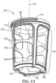
- FIGS. 1A and 1B depict an exemplary embodiment of a spray gun cup receptacle 100 according to the present disclosure.
- the spray gun cup receptacle 100 comprises an open end 110 providing access to an interior cavity 120.
- the open end 110 is a base end 130.
- the base end 130 comprises an essentially flat configuration having optional feet 132 enabling the base to be stably rested directly on a flat work surface W (not shown in FIG. 1A ).
- the number, shape, and placement of the feet 132 may be varied as needed.
- the base end 130 is not itself flat, but can be held at rest on a work surface as above with the assistance of an additional structure (i.e., a holder or the like).
- a base end plane 134 can be drawn through the base end 130 (while at rest and upright as indicated above) parallel to the work surface W, as shown in FIG 1B .
- a sidewall 140 surrounds the cavity 120 and connects the open end 110 to the base end 130.
- the sidewall 140 comprises a series of apertures 150 (at least two, but in this particular embodiment eight) that penetrate the sidewall 140 to permit the contents of the cavity 120 to be viewed therethrough.
- apertures 150 are divided by a brace member 160 and by support members 166.
- the support members 166 provide support in the axial direction (along a central axis 101, and orthogonal to the base end plane 134), while the brace member 160 provides, inter alia, hoop strength to the spray gun cup receptacle 100 at an intermediate position between the open end 110 and the base end 130.
- there could be a different number of support members 166 e.g., one, two, three, five, six, or seven or more), and that the support members 166 could be non-vertical or only generally vertical.
- vertical refers to the orientation of geometry assuming the spray gun cup receptacle 100 were resting with a flat base end 130 resting on a level, flat work surface.
- the sidewall 140 spray gun cup receptacle 100 may be highly apertured, such that relatively minimal support structure (e.g., brace member 160(s) and/or support member(s)) are provided. In such cases, it may be advantageous to construct the spray cup receptacle (particularly the sidewall 140) from a relatively strong material, such as a filled polyamide.
- the spray gun cup receptacle 100 comprises receptacle connection structure 170 proximate its open end 110.
- This receptacle connection structure 170 enables a separate lid member 300 (not shown in FIGS. 1A-1D ) to be secured to the spray gun cup receptacle 100.
- the receptacle connection structure 170 comprises threads.
- other connection structures may be employed to provide a different connection mechanism (e.g., a helical wedge connection, a snap-fit connection, a push-fit connection, a twist-lock connection, a clip connection, a latch connection, a hinged connection, or combinations thereof).
- volumetric indicia provide the painter a way to determine the volume and /or ratio of liquid component(s) in the cavity 120.
- the volumetric indicia may be provided as a separate insert 600 (see, e.g., FIGS. 4C and 5C ), imprinted or otherwise disposed on a liner 200, or otherwise positioned between the spray gun cup receptacle 100 and the cavity 120 where liquids may be contained.
- the brace member 160 are disposed at a suitable brace member 160 angle ⁇ that permits the volumetric indicia to be viewed at any height within the cavity 120.
- a suitable brace member 160 angle ⁇ that permits the volumetric indicia to be viewed at any height within the cavity 120.
- the volumetric indicia may be repeated such that an identical volume marking appears in more than one location, wherein at least one of the locations is not visually occluded by the brace member 160. In this way, the disposition of the brace member 160 can permit the volume of the contents to be accurately determined at any liquid level.
- the magnitude of the brace member 160 angle ⁇ is about 7.5 degrees as referenced from the base end plane 134.
- the magnitude of the brace member 160 angle ⁇ is about 25 degrees as referenced from the base end plane 134.
- brace member 160 angle ⁇ may be chosen as any angle greater than 0 degrees and less than 90 degrees (i.e., the brace member 160 is neither parallel nor orthogonal to the base end plane 134) that both facilitates the structural requirements of the spray gun cup receptacle 100 and also provides visibility as described herein at all levels of the cavity 120 through at least one aperture.
- a brace member 160 should divide at least two apertures 150 such that the apertures 150 are positioned - at least partially - vertically one over the other, and thus brace member 160 angles ⁇ much less than 90 degrees (e.g., 30 degrees or less) are expected for most spray gun cup receptacle 100 sizes and geometries.
- apertures 150 are divided by brace members disposed at brace member 160 angles ⁇ such that an upper aperture is positioned higher than a lower aperture, thereby permitting visibility at all liquid levels.
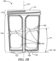
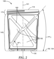
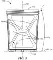
- multiple brace members 160 with different corresponding angles ⁇ 1 , ⁇ 2 , ⁇ 3 , etc. may form more complex shapes (see, e.g., FIGS. 2 and 3 ).
- the brace member 160 angle ⁇ is at least about 2 degrees as referenced from the base end plane 134. In some embodiments, the brace member 160 angle ⁇ is less than or equal to about 30 degrees as referenced from the base end plane 134. In some embodiments, the brace member 160 angle ⁇ is in a range from about 2 degrees to about 30 degrees as referenced from the base end plane 134, including, without limitation, 4, 7, 11.5, 16, and 25 degrees, including any angle therein.
- the trajectory "T" followed by the brace member 160 as it circumscribes the cavity 120 can be described as a non-circular ellipse.
- “non-circular ellipse” means an ellipse whose eccentricity is not zero.
- the eccentricity of the trajectory "T” is at least 0.03. In some embodiments, the eccentricity of the trajectory "T” is less than or equal to 0.5. In some embodiments, the eccentricity of the trajectory "T” is in a range from about 0.03 to about 0.5.
- the trajectory "T” need not be strictly elliptical in order to fall within the scope of the present disclosure.
- the spray gun cup receptacle 100 may be formed as generally cylindrical, but with a slight draft angle (e.g., approximately 3 degrees) such that its profile increases from the base end 130 to the open end 110, resulting in a trajectory "T” along the brace member 160 angle ⁇ that is generally elliptical, but in reality is slightly “egg-shaped.”
- the brace member 160 may follow a differing trajectory or trajectories.
- FIGS. 2 and 3 depict alternative embodiments of spray gun cup 500 receptacles comprising more than one brace member 160 disposed in a manner different from the embodiments of FIGS. 1A-1D .
- a brace member 160 could be provided to follow a trajectory whose brace member 160 angle ⁇ varies as its position about the sidewall 140 varies - e.g., a sinusoidal wave, a square wave, or a sawtooth pattern. Such waves or patterns could be repeating or irregular.
- spray gun cup 500 receptacles depicted herein all show a generally circular cross-section, this need not be the case.
- the cross-sectional shape of the spray gun cup receptacle 100 at any given height may comprise a polygon such as a hexagon or octagon or any other shape that permits the functional purposes set forth herein to be realized.
- the brace member 160 will be shaped and disposed to enable visibility of the cavity 120 as described elsewhere herein.
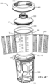
- FIG. 4A depicts a spray gun cup 500 comprising a spray gun cup receptacle 100 as shown, for example, in FIG. 1A .
- This embodiment includes a liner 200 positioned in the cavity 120 of the spray gun cup receptacle 100.
- the liner 200 has an open end 210 (see FIGS. 4C-4D ) corresponding to the open end 110 of the spray gun cup receptacle 100.
- a lid member 300 is secured to the spray gun cup receptacle 100, to the liner 200, or to both.
- the lid member 300 can be secured in many ways.
- an optional collar 400 cf. FIGS.
- the lid member 300 captures the lid member 300 and the liner 200 between the collar 400 and the spray gun cup receptacle 100 via collar connection structure 470 - in this case screw threads.
- collar connection structure 470 in this case screw threads.
- Any of the receptacle connection structures 170 earlier described may be used in similar fashion to permit an optional collar 400 to attach to the remainder of the spray gun cup 500.
- the lid member 300 itself can be provided with lid connection structure 370 to compliment the collar connection structure 470.
- the collar 400 can be configured to attach from below the lid member 300 to capture the liner 200 between the lid member 300 and the collar 400.
- the spray gun cup receptacle may remain with the spray gun cup during spraying, or the lid, liner, and collar may be detached or removed from the spray gun cup receptacle 100 as a unit during spraying (in which case the spray gun cup receptacle 100 may be primarily used as a mixing vessel only).
- the lid member 300 comprises a liquid outlet 310 and one or more outlet connection members 320 to permit the lid 300 to be connected to the liquid inlet of a spray gun.
- An outlet connection member 320 may be provided on, about, adjacent, or remote from, the liquid outlet 310 so long as it facilitates secure, liquid-tight connection to a spray gun.
- the lid comprises a filter (not shown) to permit the liquid in the spray gun cup to be filtered prior to spraying.
- the liquid outlet 310 and/or outlet connection member(s) 320 may be formed integrally with the remainder of the lid 300. Alternatively, these components may be initially formed as a separate, modular part or assembly comprising connection geometry to permit connection to the remainder of the lid 300. Example of such a configurations are depicted in FIGS. 17-18A , which each depict exemplary lid 300 comprising a modular lid base 304 and a modular liquid outlet 330 connected thereto.
- FIG. 17A and 18A depict the assemblies of FIGS. 17 and 18 , respectively, in a disassembled state, while FIG.
- a modular lid base 304 as a kit provided with a plurality of modular liquid outlets 330 configured to fit a variety of spray guns (in this case the alternate spray guns are labeled "B,” "C,” “D,” “E,” etc.).
- spray guns in this case the alternate spray guns are labeled "B,” "C,” “D,” “E,” etc.
- a common modular lid base 304 can be manufactured in a single (likely larger) tool, while the smaller modular liquid outlets 330 - which presumably would be manufactured at a lower volume - can be manufactured on smaller, less expensive tooling and equipment.
- changes in the connection geometry to a particular spray gun, or the introduction of new spray guns can be accommodated without the need to modify of the tooling for the modular lid base.
- outlet connection members 320 useful for lids 300 described herein include, for example, those shown and described in US Application No. 15/375,556 (3M Docket No. 78953US002 entitled " Reservoir systems for hand-held spray guns and methods of use"), and in US Provisional Application Nos. 62/322,492 , 62/279,619 and 62/279,537 (respective 3M Docket Nos.
- a modular liquid outlet 330 provided as above could alternatively be attached or preassembled to the end of a paint supply line or pouch etc. and in turn connected to the spray gun pain t inlet. In this way, paint could be directly to the spray gun without the need for the modular lid base 304, the liner 200, or the spray gun cup receptacle 100.
- Constructing the lid 300 using a modular liquid outlet 330 and a modular lid base 304 can provide a further advantage or allowing more complex geometries to be feasibly created than may otherwise be possible using, e.g., injection molding.
- injection molding e.g., injection molding
- tooling can be designed to directly access surfaces of each modular component that would not have been accessible on the one-piece lid.
- further geometric complexity can be achieved.
- Modular lid components may also be constructed of different materials as desirable for the application. For example, it may be desirable to use an engineering plastic for the modular liquid outlet 330 (due the strength and tolerances required for a secure and durable connection to the spray gun), while lower cost polymers could be used for the modular lid base 304.
- a modular liquid outlet 330 could be secured to the modular lid base 304 (or vice versa) in a variety of ways. For example, spin welding, sonic welding, quarter turn locking, other mechanical locking mechanisms, glues/adhesives, threaded, other mechanical fasteners i.e. screws, rivets and/or molded posts that are cold formed/hot formed and mushroomed down to hold/retain the component(s) in place and provide a suitable leak-proof seal.
- the modular liquid outlet 330 is located against and secured to the modular lid base 304 with the aid of a sealing feature 306 and an alignment feature 309.
- the sealing feature 306 is on the modular lid base 304 and comprises a cylindrical protrusion 307 comprising a one or a plurality of radial sealing ribs 308 adapted to interact with an interior surface 311 of liquid outlet 310 to create a liquid-tight seal upon assembly of the modular liquid outlet 330 to the modular lid base 304.
- the alignment features 309 assist to locate the two parts together and also to resist relative rotation of the parts once assembled.
- the two parts may be additionally secured by an adhesive, welding, or the like after assembly, if desired.
- the fit between the modular liquid outlet 330 and the modular lid base 304 may be constructed to be sufficiently secure without the aid of further fasteners (e.g., by way of a friction fit, snap-fit, thread, or the like). Sealing features 306 and/or alignment features 309, where used, may be interchanged between the two parts as appropriate.
- the modular liquid outlet 330 is secured to the modular lid base 304 by way of welding and/or an adhesive or the like.
- the adhesive joint and/or weld joint act to both retain and create a liquid-tight seal upon assembly of the modular liquid outlet 330 to the modular lid base 304.
- lids 300 described herein and depicted throughout FIGS. 1-16B could be constructed in a modular fashion and/or provided in kits as described in the preceding several paragraphs and depicted in FIGS. 17-19 .
- FIG. 4B depicts an embodiment as in FIG. 4A further including volumetric indicia V as described elsewhere herein.
- FIG. 4C depicts an exploded view of a spray gun cup 500 including volumetric indicia provided on an insert 600.
- the insert 600 may comprise a sheet that is deformable to the cavity of the spray gun cup receptacle upon insertion.
- an insert 600 could be provided as a pre-molded unit that could drop into the spray gun cup receptacle 100 without deformation.
- An insert 600 may be constructed such that the insert 600 is registered in the cavity and with respect to the apertures and thus generally fixed against rotation.
- the insert 600 may be provided as described above with repeating volumetric indicia "V" such that each liquid level is visible from at least one position about the spray gun cup receptacle.
- the insert 600 may be registerable in more than one location such that the insert can be inserted and fixed in more than one position.
- FIG. 4D depicts an exploded view of a spray gun cup 500 not including volumetric indicia V, but wherein the contents of the cavity are nonetheless visible at all fluid levels through at least one aperture as described elsewhere herein.
- the liner is generally constructed from a transparent or translucent material.
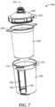
- FIG. 5A depicts a spray gun cup 500 different from the one depicted in FIG. 4A in that no collar 400 is used. Rather, the lid member 300 is adapted to be secured without the need of a collar.
- the lid member 300 may be provided with lid connection structure 370 that may have alternatively been provided on a collar 400.
- the lid member 300 may itself screw directly (via lid connection structure 370) into - or on to, or both - the spray gun cup receptacle 100.
- the lid member 300 could comprise lid connection structure 370 to compliment receptacle connection structure 170 as previously discussed with respect to FIG. 1A (e.g., a snap-fit connection, a push-fit connection, a twist-lock connection, a clip connection, a latch connection, a hinged connection, or combinations thereof).
- FIG. 5B depicts an embodiment as in FIG. 5A further including volumetric indicia V as described elsewhere herein.
- FIG. 5C depicts an exploded view of a spray gun cup 500 including volumetric indicia provided on an insert 600.
- the insert 600 may comprise a sheet that is deformable to the cavity of the spray gun cup receptacle 100 upon insertion.
- an insert 600 could be provided as a pre-molded unit that could drop into the spray gun cup receptacle 100 without deformation.
- FIG. 5D depicts an exploded view of a spray gun cup 500 not including volumetric indicia, but wherein the contents of the cavity are nonetheless visible at all fluid levels through at least one aperture as described elsewhere herein.
- the lid connection structure 370 comprises a snap-fit connection with complimentary receptacle connection structure 170.
- the liner is generally constructed from a transparent or translucent material.
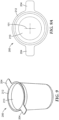
- FIGS. 6 through 8 depict additional embodiments of a spray gun cup 500 that, like the embodiments of FIGS. 5A-5D , have a lid 300 connected directly to the receptacle connection structure 170 without the need of a separate collar 400.
- An exemplary liner for use with such a spray gun cup 500 is shown in FIGS. 9-9A , while an exemplary spray gun cup receptacle is shown in FIGS. 10-10A , and various lids 300 are depicted in FIGS. 11-16B .
- the spray gun cup receptacle 100 comprises one or more apertures 150.
- apertures 150 could be provided in the manner described above (i.e., intersected by one or more brace members), no brace members are shown here.
- a tactile feedback member 152 may be provided as a recess in the outer wall 104, or, e.g., as a texture on the outer wall 104.
- the tactile feedback member(s) allow a user to know, without looking at the spray gun cup 500, that they are gripping an area adjacent an aperture, such that they can properly locate their hand(s) and avoid inadvertently applying excess pressure (such as by squeezing) to the liner 200 through the aperture(s). It has been found that squeezing the liner 200 when it is filled with paint can cause spilling of paint (by forcing paint upward an out of the open end 210 of the liner 200 or accidental disconnection of the lid 300 from the liner 200 through excess deformation of the open end 210 of the liner 200.
- the aperture 150 shown in FIG. 6 can additionally be used to assist a user when he or she wishes to remove the liner 200 from the lid 300. This may be desired in order to, for example, refill or add additional liquid to the liner. In particular, the user may insert a finger (or a thumb and finger) through the aperture 150 to grip the liner 200 and, while doing so, carefully lift the lid 300 away from the liner 200 to add additional liquid.
- This use of the aperture 150 to assist with liner/lid separation may be advantageous over the alternative of first removing the entire lid/liner assembly from the receptacle and then separating the two, because in this case the liner 200 can remain essentially supported by the receptacle 100, thereby reducing the risk of spillage.
- FIGS. 6-16B comprise a different configuration of aperture as compared to FIGS. 1-5D
- any of the lids 300 and spray gun cup receptacles 100 described herein could be used with one another provided any necessary modifications are made to the respective receptacle, lid, and/or optional collar connection structures (170, 370, 470, respectively).
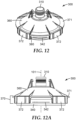
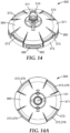
- FIGS. 11-16B depict various lids useful with spray gun cup 500 receptacles described herein.
- the lid 300 comprises one or more liner sealing members 340.
- a liner sealing member 340 functions as follows: a liner 200 is inserted into the open end 110 of a spray gun cup receptacle 100; paint is added through the open end 110 of the liner 200; a lid 300 it positioned in the open end 110 of the liner 200 (and receptacle); the lid 300 is secured to the receptacle in a direction along the central axis 101 such that the open end 110 of the liner 200 is stretched radially over the liner sealing member 340 and finally into full sealing engagement.
- a liner sealing member 340 may comprise one or more radially-outwardly protruding features, such as those shown in FIGS. 11-11E and 15-19 .
- a liner sealing member may additionally (or alternatively) comprise a chamfered or otherwise tapered surface, such as those shown in FIGS. 12-14A .
- the lid 300 may further comprise a liner seal catch 342, an example of which is most clearly depicted in FIGS. 12-13A .
- a liner seal catch 342 can enhance liner retention on the lid 340 and can assist in providing tactile and/or audible reassurance to the end user that the lid 300 is securely seated in the liner 200 by permitting a "snapping" action as discussed in more detail elsewhere in this specification.
- a liner seal catch 342 is particularly suited for use in conjunction with a chamfered or otherwise tapered liner sealing member 340 as described above because such a tapered surface may lack other features that could assist in resisting against the liner 200 being pulled away from the lid (e.g., the radially-outwardly protruding features shown with the liner sealing member 340 in FIGS. 11-11E and 15-19 ). However, a liner seal catch 342 may be employed as additional support even in those constructions.
- the entire spray gun cup 500 may be discarded after use, users may wish to remove the liner 200 from the lid 300 either to add additional paint or to replace the lid 300 with a fresh one (e.g., when a filter 301 in the lid 300 has become clogged or when paint has dried thereon).
- a liner 200 can be difficult to remove from the lid 300 without damaging the liner 200 or spilling paint. Therefore, the liner 200 may be provided with one or more release tabs 204 that facilitate easy removal of the liner 200 from the lid 300 after assembly. These release tabs 204 are depicted in greater detail in FIGS.
- FIG. 8 depicts an embodiment wherein the liner 200 optionally does not comprise release tabs 204.
- the user may rely upon gripping the liner 200 through the aperture 150 in lieu of a liner release tab 204.
- Release tabs 204 may be used alone or in conjunction with gripping through an aperture 150.
- the lid 300 may comprise a lid body 360 and be provided with a flange 371 about its periphery.
- the flange 371 carries at least a portion of the lid connection structure 370, and in particular the lid engagement member(s) 372.
- one or more flange openings 380 are provided such that the flange 371 is interrupted about its periphery.
- the flange opening(s) 380 can allow clearance for the release tab(s) 204 on the liner 200 to extend from the spray gun cup 500 for convenient gripping and lifting of the liner 200. As shown, the flange opening(s) 380 penetrate the lid connection structure 370.
- flange tabs 372 upon which are provided lid engagement members 374 to interact with complementary features on the receptacle connection structure 170.
- the presence of flange openings 380 can allow access for tooling (for example, injection molding tooling) to form a liner seal catch 342).
- the receptacle engagement member(s) 172 and lid engagement member(s) 372 comprise an easy-start partial thread whereby the lid 300 is easily aligned and attached to the receptacle 100 with a partial turn.
- a receptacle engagement member 174 comprising an easy-start partial thread is shown in greater detail in FIGS. 10 and 10A .
- the receptacle engagement member 174 comprises a camming surface 176 facing away from the open end 110 of the spray gun cup receptacle 100.
- the camming surface 176 may be linearly inclined, as shown, or may be flat (not inclined), curved, or may comprise any combination of inclined, flat, and/or curved portions.
- an inclined or curved surface portion may be provided on the complementary lid camming surface 376 (described in greater detail elsewhere) such that a camming action is facilitated when the parts interact.
- the camming surface 176 it is adapted interact with complementary structure on the lid 300 to permit the lid 300 to be securely attached to the spray gun cup receptacle 100 such that the liner 200 is retained in sealing relation between the lid 300 and the receptacle.
- features 176 and 376 are referred to as "camming surfaces,” it is not strictly necessary for a camming action (which should be understood herein as including an application of force along the central axis) to occur during interaction. Rather, in some embodiments (see, e.g., the particular twist-lock embodiment described below), the respective lid and receptacle engagement members (374, 174), which may carry camming surfaces (376, 176) need not apply axial forces during installation and/or removal.
- the receptacle engagement member 174 is additionally equipped with a stop feature 178 that prevents over-rotation of the lid 300 during installation and provides the user an indication that the lid 300 has been fully installed onto the spray gun cup receptacle (see, e.g., FIGS. 10-10A ).
- a stop feature 178 when optionally provided, may be formed as a continuation of the camming surface 176 (as shown), or may be spaced from the camming surface 176. It has been found that the presence of a stop feature 178 can be especially beneficial on disposable (e.g., plastic) parts where over-rotation can cause deformation of engaging features and ultimately lead to potential failure of the connection.
- the lid engagement members 374 are adapted to align and cooperate with the receptacle engagement members 174 such that the lid 300 (i) can be "snapped" into the liner 200; (i) will not cross-thread; and (iii) will resist being rotated in the wrong direction at the beginning of assembly of the lid to the spray gun cup receptacle.
- a series of design features are employed (while all features are used together in the embodiments shown, they are not intended to be disclosed as inextricably linked, as each can provide benefits without the need of the other(s)).
- One feature comprises spaces between adjacent receptacle engagement members 174 that permit a lid engagement member 374 to pass fully through until the lid is essentially fully seated against the spray gun cup receptacle (and/or liner 200) - although not yet fully sealed and tightened - prior to engagement of camming surfaces on either part.
- the lid can be "snapped" onto the liner in one brief motion, as opposed to, for example, advancing the two parts together gradually as a thread is tightened.
- the "snapping" sensation and/or sound derives from a combination of: (i) the liner sealing member(s) 340 being quickly advanced into the open end 210 of the liner 200 such that a portion of the liner 200 rapidly stretches over the liner sealing member 340 and then relaxes; and (ii) the lid rim 312 accordingly impacting the liner rim 212 / receptacle rim 112 as the lid 300 quickly drops into contact.
- This brief snapping sensation can provide tactile and/or audible reassurance to the end user that the lid 300 and liner 200 are securely attached, although the lid has yet to be secured to the spray gun cup receptacle 100.
- the end user would (i) align the respective lid and receptacle engagement members (374, 174); (ii) snap the lid into the liner; and (iii) twist the lid to engage the lid engagement member 374 against the receptacle engagement member 174 in a non-camming fashion, such that the respective engagement members prevent the lid from being pulled off the of the spray gun cup receptacle along the central axis, but don't necessary provide any compression of the lid 300 against the spray gun cup receptacle 100 or the liner rim 212.
- a rear portion 379 of a lid engagement member 374 is located at a vertical position along the central axis 101 that interferes with a forward portion 179 of the adjacent receptacle engagement member 174 such that the lid cannot be rotated in the reverse direction. Instead, the end user need only rotate the lid in the correct direction to finally lock the lid and liner against the spray gun cup receptacle 100.
- the lid is (i) easily rotationally aligned; (ii) easily brought into the correct axial position against the spray gun cup receptacle; (iii) snapped in place to give reassurance of secure connection; (iv) prevented from rotating in the wrong direction; and (v) easily rotated in the correct direction without risk of cross-threading to engage respective camming surfaces to fully seal and tighten.
- Provision of the receptacle engagement member(s) 172 as an easy-start partial thread as shown can not only make installation of the lid faster, but it can prevent possible cross-threading, reduce the number of areas where excess paint can collect and foul the assembly, and ease cleanup.
- the lid comprises four flange tabs 372 - one corresponding to each receptacle engagement member 174.
- the flange tabs 372 may be provided as independent members protruding along the central axis 101 from a radially-outer periphery of the lid 300, as shown for example in FIGS. 11-12E and 15-16B .
- flange tabs 372 may be connected by flange bridging members 382.
- flange openings 380 may be provided in the area(s) between flange tabs 372.
- Flange openings 380 can permit clearance for, for example, liner release tabs 204 as discussed elsewhere, and may additionally provide access for the fingers of an end user to assist in gripping the lid 300 for installation and removal. Such additional gripping functionality may be particularly desirable where end users may be likely to be wearing gloves, and where the end user's hands (gloved or otherwise) may be slippery with wet paint.
- an additional benefit may be realized in that an end user can more easily lift or pry the flange tab 372 upwardly if necessary to release the lid 300 from the spray gun cup receptacle. Such prying would require significantly greater force were the flange 371 not interrupted by flange openings 380. Such lifting or prying may be advantageous in embodiments where the lid 300 is a snap-fit or friction-fit onto the spray gun cup receptacle 100, but may also be useful in removing a lid 300 that has been threaded in place (for example, if a spill or excess paint has dried in the assembly, making removal by turning difficult).
- one or more access windows 373 are provided in the flange 371 corresponding to the lid engagement member(s) 374.
- the access window(s) 373 can provide access by slides in injection-molding tooling for formation of features that would otherwise be underlying the flange tabs 372 - for example, the lid camming surface(s) 376 on lid engagement member(s) 374.
- the lid camming surfaces 376 are visible through the access windows 373 looking from the top of the lid 300.
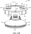
- the flange 371 is formed integrally with the lid 300 (i.e., the lid body 360 and the flange 371 are integral).
- the flange 371 is initially formed independently of the lid body 360 and subsequently attached to form the competed lid 300.
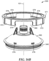
- the flange 371, after attachment to the lid body 360 may be configured to rotate relative to the lid body 360 (as in FIGS. 16-16B ), or may be rotationally fixed relative to the lid body 360 (as in FIGS. 15-15B ).
- interaction of the flange 371 and the lid body 360 can permit the lid body 360 to remain in fixed sealing relation against the liner 200 and/or the spray gun cup receptacle 100 while the flange 371 is rotated to cause engagement of the lid connection structure 370 with the receptacle connection structure 170.
- Such relative movement can assist in both (i) providing a seal between the lid and liner and/or spray gun cup receptacle, and (ii) reducing the rotational force required to install the lid.
- the flange 371 may be retained on the lid 300 via one or more flange retention features 378. Exemplary embodiments comprising flange retention features 378 are shown in FIGS. 15 -16B .
- the flange 371 is rotationally fixed relative to the lid 300.
- the flange 371 is permitted to rotate relative to the lid 300. In some embodiments, rotation is permitted about a full three-hundred-sixty degrees about the central axis 101, while in others rotation may be limited to a partial turn such as, for example, ninety degrees.
- a flange rotation limiting feature 377 may be provided on one or both of the lid body 360 and/or the flange 371 (see, e.g., FIGS. 16C and 16D .
- flange rotation limiting features 377 are provided on the flange 371 such that they will rotate through a predetermined arc until contact is made with a flange retention feature 378 on the lid body 360.
- a separate flange 371 may be assembled in sealing relation with respect to the lid body 360, even if the flange 371 can rotate relative to the lid body 360 (e.g., by providing a sealing gasket, etc.).
- the lid body 360 carries a liner sealing member (for example, on a skirt protruding from beneath the lid body as shown in in figures) and further comprises an inner lid body surface 361 that funnels paint to the liquid outlet.
- the lid body 361 forms a liquid conduit for the paint to flow from the liner into the spray gun such that a separate flange 371 can be movably connected to the lid body without worry of creating a leak path for paint.
- the liner 200 comprises a liner rim 212 surrounding the liner open end 210 that can provide additional sealing functionality when clamped between the lid 300 and the spray gun cup receptacle 100.
- the lid 300 may be provided with a lid rim 312 and the spray gun cup receptacle 100 with a receptacle rim 112 surrounding the open end 110.
- the camming surface 176 - through interaction with a lid camming surface 376 on lid engagement members 374 - enables a clamping force to be applied along the central axis 101 when the lid 300 is attached to the spray gun cup receptacle 100.
- one or both or the camming surface 176 and/or lid camming surface 376 is provided with geometry to cause relative clamping motion of the lid 300 and the receptacle along the central axis 101 during connection.
- such geometry may be provided - at least in part - by an inclined or curved camming surface portion as described above on either or both the camming surface 176 and/or lid camming surface 376.
Claims (9)
- Ein Spritzpistolenbecher, aufweisend eine Spritzpistolenbecheraufnahme (100), eine Auskleidung (200) und ein Deckelelement (300),wobei die Spritzpistolenbecheraufnahme (100) aufweistein offenes Ende (110) zum Aufnehmen der Auskleidung (200) innerhalb eines Hohlraums (120);ein Basisende (130) gegenüber dem offenen Ende (110), wobei das Basisende (130) in Bezug auf eine Arbeitsoberfläche (W) derart mit dem offenen Ende (110) nach oben weisend positionierbar ist, dass eine Basisebene (134), die durch das Basisende (130) verläuft, parallel zu der Arbeitsoberfläche (W) ist;eine Seitenwand (140), die den Hohlraum (120) umgibt und das offene Ende (110) mit dem Basisende (130) verbindet, die Seitenwand (140) aufweisend eine oder mehrere Öffnungen (150), durch die der Hohlraum (120) von außerhalb der Spritzpistolenbecheraufnahme (100) sichtbar ist; undein taktiles Rückmeldungselement (152), das an der Seitenwand (140) direkt benachbart an eine der einen oder der mehreren Öffnungen (150) positioniert ist, wobei das taktile Rückmeldungselement (152) einem Benutzer ermöglicht zu wissen, ohne auf die Spritzpistolenbecheraufnahme (100) zu schauen, dass ein Bereich angrenzend an eine Öffnung (150) ergriffen wird; undwobei die Auskleidung (200) konfiguriert ist, um in dem Hohlraum (120) positioniert zu sein, die Auskleidung (200) aufweisend ein offenes Ende (210), das dem offenen Ende (110) der Spritzpistolenbecheraufnahme (100) entspricht;wobei der Spritzpistolenbecher derart konfiguriert ist, dass die Auskleidung (200) in das offene Ende (110) der Spritzpistolenbecheraufnahme (100) eingeführt wird, Farbe durch das offene Ende (210) der Auskleidung (200) hinzugefügt werden kann, und das Deckelelement (300) in dem offenen Ende (210) der Auskleidung (200) positioniert werden kann, wobei das Deckelelement (300) konfiguriert ist, um an der Spritzpistolenbecheraufnahme (100) in einer Richtung entlang einer Mittelachse (101) befestigt zu werden, sodass das offene Ende (210) der Auskleidung (200) radial über ein Auskleidungsdichtungselement (340) des Deckelelements (300) und schließlich in vollständigen Dichteingriff gespannt ist;und wobei das taktile Rückkopplungselement (152) einen Vorsprung aufweist, der sich von der Seitenwand (140) radial nach außen erstreckt.
- Der Spritzpistolenbecher nach Anspruch 1, wobei zwei Öffnungen (150) übereinander durch ein Verstrebungselement (160) geteilt sind, wobei mindestens ein Abschnitt davon in einem Verstrebungselementwinkel α relativ zu der Basisebene (134) angeordnet ist, wobei der Verstrebungselementwinkel α größer als 0 Grad und kleiner als 90 Grad ist, vorzugsweise wobei der Verstrebungselementwinkel α ausreicht, um den Hohlraum (120) durch mindestens eine der zwei Öffnungen (150) an einer beliebigen vertikalen Position innerhalb des Hohlraums sichtbar zu machen.
- Der Spritzpistolenbecher nach Anspruch 2, wobei das Verstrebungselement (160) eine Verstrebungselementbahn (T) um den Hohlraum (120) herum definiert, wobei die Verstrebungselementbahn (T) eine nicht kreisförmige Ellipse aufweist.
- Der Spritzpistolenbecher nach einem der Ansprüche 2 bis 3, wobei der Verstrebungselementwinkel α mindestens 2 Grad beträgt.
- Der Spritzpistolenbecher nach einem der Ansprüche 2 bis 4, wobei der Verstrebungselementwinkel α kleiner als oder gleich 30 Grad ist.
- Der Spritzpistolenbecher nach einem der Ansprüche 1 bis 5, wobei das offene Ende (110) der Spritzpistolenbecheraufnahme (100) eine Aufnahmeverbindungsstruktur (170) aufweist, um zu ermöglichen, dass das Deckelelement (300) an dem offenen Ende (110) der Spritzpistolenbecheraufnahme (100) befestigt werden kann.
- Der Spritzpistolenbecher nach Anspruch 6, wobei die Aufnahmeverbindungsstruktur (170) ermöglicht, dass das Deckelelement (300) durch eines der Folgenden zu befestigen ist: eine Gewindeverbindung, eine spiralförmige Keilverbindung, eine Schnappverbindung, eine Steckverbindung, einer Drehriegelverbindung, eine Clipverbindung, eine Laschenverbindung oder Kombinationen davon.
- Der Spritzpistolenbecher nach einem der Ansprüche 2 bis 7, wobei die Seitenwand (140) ein oder mehrere im Allgemeinen vertikale Stützelemente (166) aufweist, die das Verstrebungselement (160) schneiden.
- Der Spritzpistolenbecher nach einem der Ansprüche 1 bis 8, aufweisend volumetrische Markierungen V, die positioniert sind, um durch die Öffnungen (150) sichtbar zu sein und ein Volumen von Inhalt der Auskleidung anzugeben.
Applications Claiming Priority (2)
| Application Number | Priority Date | Filing Date | Title |
|---|---|---|---|
| US201662279310P | 2016-01-15 | 2016-01-15 | |
| PCT/US2017/013120 WO2017123708A1 (en) | 2016-01-15 | 2017-01-12 | Spray gun cups, receptacles, and methods of use |
Publications (2)
| Publication Number | Publication Date |
|---|---|
| EP3402603A1 EP3402603A1 (de) | 2018-11-21 |
| EP3402603B1 true EP3402603B1 (de) | 2023-05-24 |
Family
ID=57915109
Family Applications (1)
| Application Number | Title | Priority Date | Filing Date |
|---|---|---|---|
| EP17702207.6A Active EP3402603B1 (de) | 2016-01-15 | 2017-01-12 | Spritzpistolenbecher, behälter und verfahren zur verwendung |
Country Status (8)
| Country | Link |
|---|---|
| US (1) | US10688510B2 (de) |
| EP (1) | EP3402603B1 (de) |
| JP (2) | JP2019508229A (de) |
| CN (2) | CN108698062A (de) |
| AU (1) | AU2017207352B2 (de) |
| CA (1) | CA3011435A1 (de) |
| ES (1) | ES2949320T3 (de) |
| WO (1) | WO2017123708A1 (de) |
Families Citing this family (11)
| Publication number | Priority date | Publication date | Assignee | Title |
|---|---|---|---|---|
| MX2016007249A (es) | 2013-12-05 | 2017-01-05 | 3M Innovative Properties Co | Contenedor para dispositivo atomizador. |
| WO2017007911A1 (en) * | 2015-07-08 | 2017-01-12 | 3M Innovative Properties Company | Spray gun cups, receptacles, and methods of use |
| EP3842154A1 (de) | 2016-01-15 | 2021-06-30 | 3M Innovative Properties Company | Verbindungssystem für handgehaltene sprühpistolen |
| US11638924B2 (en) | 2016-01-15 | 2023-05-02 | 3M Innovative Properties Company | Spray gun cups, receptacles, lids, and methods of use |
| WO2017123708A1 (en) * | 2016-01-15 | 2017-07-20 | 3M Innovative Properties Company | Spray gun cups, receptacles, and methods of use |
| US10689165B2 (en) | 2016-01-15 | 2020-06-23 | 3M Innovative Properties Company | Reservoir systems for hand-held spray guns and methods of use |
| EP3402604B1 (de) | 2016-01-15 | 2021-03-03 | 3M Innovative Properties Company | Weitmundiger flüssigkeitsverbinder für handspritzpistolen |
| US11040361B2 (en) | 2016-01-15 | 2021-06-22 | 3M Innovative Properties Company | Modular spray gun lid assemblies and methods of design and use |
| CA3046731A1 (en) * | 2016-12-12 | 2018-06-21 | 3M Innovative Properties Company | Reservoir systems for hand-held spray guns |
| EP3902634A1 (de) | 2018-12-27 | 2021-11-03 | 3M Innovative Properties Company | Flüssigkeitsabgabeanordnung für eine sprühvorrichtung |
| USD952097S1 (en) * | 2020-07-14 | 2022-05-17 | Yuyao Yufeng Scutcheon Plastic Factory | Paint spraying pot lid |
Citations (3)
| Publication number | Priority date | Publication date | Assignee | Title |
|---|---|---|---|---|
| JP3052058U (ja) * | 1998-03-06 | 1998-09-11 | 株式会社ヨトリヤマ | 塗料吸上げ式スプレー塗装機の塗料容器 |
| WO2013003592A2 (en) * | 2011-06-30 | 2013-01-03 | Saint-Gobain Abrasives, Inc. | Paint cup assembly |
| WO2017007911A1 (en) * | 2015-07-08 | 2017-01-12 | 3M Innovative Properties Company | Spray gun cups, receptacles, and methods of use |
Family Cites Families (55)
| Publication number | Priority date | Publication date | Assignee | Title |
|---|---|---|---|---|
| US3157360A (en) * | 1963-02-25 | 1964-11-17 | William L Heard | Spray gun having valved flexible liner |
| US3401842A (en) * | 1966-11-28 | 1968-09-17 | Betty L Morrison | Combination paint cup and filler for spray guns |
| US4174071A (en) * | 1976-11-08 | 1979-11-13 | Binks Manufacturing Company | Spray gun assembly |
| JPS629966Y2 (de) * | 1981-05-08 | 1987-03-09 | ||
| FR2620424B1 (fr) | 1987-09-15 | 1989-12-15 | Morel Simone | Conteneur a capuchon amovible a generatrices laterales alignees |
| GB2298194A (en) | 1995-02-24 | 1996-08-28 | Beeson & Sons Ltd | Child resistant closures for containers |
| DE03020831T1 (de) | 1997-01-24 | 2005-01-13 | 3M Company (N.D.Ges.D. Staates Delaware), St. Paul | Vorrichtung zum Zerstäuben von Flüssigkeiten, Einwegbehälter und Behälterinliner dafür |
| US6820824B1 (en) | 1998-01-14 | 2004-11-23 | 3M Innovative Properties Company | Apparatus for spraying liquids, disposable containers and liners suitable for use therewith |
| CN2337882Y (zh) * | 1998-09-21 | 1999-09-15 | 萧吴桂兰 | 一种茶叶冲泡器 |
| US6375031B1 (en) | 1999-07-26 | 2002-04-23 | Merry Chance Industries, Ltd. | Container for liquids having viewing window |
| US6536687B1 (en) | 1999-08-16 | 2003-03-25 | 3M Innovative Properties Company | Mixing cup adapting assembly |
| GB0110025D0 (en) * | 2001-04-24 | 2001-06-13 | 3M Innovative Properties Co | Improvements in or relating to liquid spraying apparatus |
| US7188785B2 (en) * | 2001-04-24 | 2007-03-13 | 3M Innovative Properties Company | Reservoir with refill inlet for hand-held spray guns |
| US6588681B2 (en) * | 2001-07-09 | 2003-07-08 | 3M Innovative Properties Company | Liquid supply assembly |
| AUPR991202A0 (en) | 2002-01-10 | 2002-01-31 | Owens-Illinois Closure Inc. | A self-venting sports type closure |
| DE20202123U1 (de) | 2002-02-13 | 2003-02-06 | Sata Farbspritztechnik | Farbspritzpistole |
| US6739781B2 (en) | 2002-04-22 | 2004-05-25 | Seaquist Closures Foreign, Inc. | Scrubbing structure |
| GB0224698D0 (en) | 2002-10-24 | 2002-12-04 | 3M Innovative Properties Co | Easy clean spray gun |
| US6953155B2 (en) * | 2002-10-24 | 2005-10-11 | 3M Innovative Properties Company | Pressure assisted liquid supply assembly |
| US7845582B2 (en) * | 2002-12-18 | 2010-12-07 | 3M Innovative Properties Company | Spray gun reservoir with oversize, fast-fill opening |
| US6796514B1 (en) * | 2003-05-02 | 2004-09-28 | 3M Innovative Properties Company | Pre-packaged material supply assembly |
| US6945429B2 (en) | 2003-06-10 | 2005-09-20 | Illinois Tool Works Inc. | Disposable paint cup attachment system for gravity-feed paint sprayer |
| FR2859118B1 (fr) | 2003-08-26 | 2007-03-09 | Michel Camilleri | Godet jetable a monter sur un pistolet pour la preparation, l'application et la conservation d'une peinture |
| CA2448110A1 (en) | 2003-11-05 | 2005-05-05 | Simon Yechouron | Paint gun accessory |
| US7124907B2 (en) * | 2003-12-02 | 2006-10-24 | Evenflo Company, Inc. | Sippy straw cup |
| US7086549B2 (en) * | 2004-01-16 | 2006-08-08 | Illinois Tool Works Inc. | Fluid supply assembly |
| DE102004003438A1 (de) | 2004-01-22 | 2005-08-18 | Sata Farbspritztechnik Gmbh & Co.Kg | Fließbecher für eine Farbspritzpistole |
| DE202004003116U1 (de) | 2004-02-28 | 2005-07-14 | Sata Farbspritztechnik Gmbh & Co.Kg | Fließbecher für eine Farbspritzpistole |
| DK1835997T3 (da) * | 2004-12-16 | 2012-09-24 | Saint Gobain Abrasives Inc | Væskeforsyningsskål og inderbeholderanordning til sprøjtepistoler |
| WO2007149760A2 (en) * | 2006-06-20 | 2007-12-27 | Louis M. Gerson Co., Inc. | Liquid supply assembly |
| CN100457001C (zh) * | 2007-02-01 | 2009-02-04 | 陈俊平 | 带有防护装置的密封弹压活塞式冲泡器 |
| EP2000218A1 (de) * | 2007-06-07 | 2008-12-10 | S.A. Omniform | Selbsttätiges Lüftungsventil für einen Farbversorgungsbehälter |
| NL1033999C2 (nl) | 2007-06-18 | 2008-12-22 | Emm Productions B V | Deksel voor een spuitbeker, werkwijze voor het vrijgeven van een balg in een spuitbeker en een flens voor plaatsing tussen een spuitbeker en een deksel. |
| US8365933B2 (en) | 2007-07-13 | 2013-02-05 | Aptar Freyung Gmbh | Closure system for a container and dispensing closure |
| DE102007048440B3 (de) | 2007-10-02 | 2009-04-16 | G-Mate Ag | Deckel für Mischbecher von Farbspritzpistolen |
| US8647574B2 (en) * | 2007-11-20 | 2014-02-11 | 3M Innovative Properties Company | Sample preparation container and method |
| DE202011100181U1 (de) | 2011-05-03 | 2012-08-06 | Geka Gmbh | Applikatorschnellverschluss |
| US9335198B2 (en) * | 2011-05-06 | 2016-05-10 | Saint-Gobain Abrasives, Inc. | Method of using a paint cup assembly |
| CN202069877U (zh) * | 2011-05-10 | 2011-12-14 | 河南中医学院 | 一种多功能煎药锅 |
| EP2766126B1 (de) * | 2011-10-12 | 2019-11-27 | 3M Innovative Properties Company | Sprühkopfanordnungen für flüssigkeitsspritzpistolen |
| CN107262308B (zh) | 2011-10-27 | 2022-07-08 | 固瑞克明尼苏达有限公司 | 具有可收缩衬管的喷涂器流体供应系统 |
| US9802213B2 (en) * | 2012-03-06 | 2017-10-31 | 3M Innovative Properties Company | Spray gun having internal boost passageway |
| US9352343B2 (en) * | 2013-01-22 | 2016-05-31 | Carlisle Fluid Technologies, Inc. | Liquid supply system for a gravity feed spray device |
| EP2994240B1 (de) | 2013-05-08 | 2019-02-13 | Graco Minnesota Inc. | Farbdosenadapter für tragbare sprühvorrichtung |
| US20150108135A1 (en) | 2013-10-17 | 2015-04-23 | Fadi Hanna | Disposable components for a spray gun |
| MX2016007249A (es) * | 2013-12-05 | 2017-01-05 | 3M Innovative Properties Co | Contenedor para dispositivo atomizador. |
| US9796492B2 (en) * | 2015-03-12 | 2017-10-24 | Graco Minnesota Inc. | Manual check valve for priming a collapsible fluid liner for a sprayer |
| CN204813201U (zh) * | 2015-06-19 | 2015-12-02 | 合肥伊佳欢家庭用品有限公司 | 一种新型口杯联接支架 |
| JP2019504753A (ja) | 2016-01-15 | 2019-02-21 | スリーエム イノベイティブ プロパティズ カンパニー | 手持ち式スプレーガン用のボタンロック流体コネクタ |
| US11040361B2 (en) * | 2016-01-15 | 2021-06-22 | 3M Innovative Properties Company | Modular spray gun lid assemblies and methods of design and use |
| US11638924B2 (en) * | 2016-01-15 | 2023-05-02 | 3M Innovative Properties Company | Spray gun cups, receptacles, lids, and methods of use |
| WO2017123708A1 (en) * | 2016-01-15 | 2017-07-20 | 3M Innovative Properties Company | Spray gun cups, receptacles, and methods of use |
| EP3402604B1 (de) | 2016-01-15 | 2021-03-03 | 3M Innovative Properties Company | Weitmundiger flüssigkeitsverbinder für handspritzpistolen |
| US10689165B2 (en) | 2016-01-15 | 2020-06-23 | 3M Innovative Properties Company | Reservoir systems for hand-held spray guns and methods of use |
| EP3842154A1 (de) | 2016-01-15 | 2021-06-30 | 3M Innovative Properties Company | Verbindungssystem für handgehaltene sprühpistolen |
-
2017
- 2017-01-12 WO PCT/US2017/013120 patent/WO2017123708A1/en active Application Filing
- 2017-01-12 CA CA3011435A patent/CA3011435A1/en not_active Abandoned
- 2017-01-12 US US16/069,830 patent/US10688510B2/en active Active
- 2017-01-12 ES ES17702207T patent/ES2949320T3/es active Active
- 2017-01-12 CN CN201780010673.7A patent/CN108698062A/zh active Pending
- 2017-01-12 AU AU2017207352A patent/AU2017207352B2/en not_active Ceased
- 2017-01-12 JP JP2018536797A patent/JP2019508229A/ja active Pending
- 2017-01-12 EP EP17702207.6A patent/EP3402603B1/de active Active
- 2017-01-12 CN CN202011572636.5A patent/CN112756126A/zh active Pending
-
2021
- 2021-03-05 JP JP2021034875A patent/JP7030227B2/ja active Active
Patent Citations (3)
| Publication number | Priority date | Publication date | Assignee | Title |
|---|---|---|---|---|
| JP3052058U (ja) * | 1998-03-06 | 1998-09-11 | 株式会社ヨトリヤマ | 塗料吸上げ式スプレー塗装機の塗料容器 |
| WO2013003592A2 (en) * | 2011-06-30 | 2013-01-03 | Saint-Gobain Abrasives, Inc. | Paint cup assembly |
| WO2017007911A1 (en) * | 2015-07-08 | 2017-01-12 | 3M Innovative Properties Company | Spray gun cups, receptacles, and methods of use |
Also Published As
| Publication number | Publication date |
|---|---|
| US10688510B2 (en) | 2020-06-23 |
| JP2021098198A (ja) | 2021-07-01 |
| CN108698062A (zh) | 2018-10-23 |
| US20190009290A1 (en) | 2019-01-10 |
| JP2019508229A (ja) | 2019-03-28 |
| CA3011435A1 (en) | 2017-07-20 |
| ES2949320T3 (es) | 2023-09-27 |
| EP3402603A1 (de) | 2018-11-21 |
| AU2017207352B2 (en) | 2019-09-12 |
| JP7030227B2 (ja) | 2022-03-04 |
| CN112756126A (zh) | 2021-05-07 |
| WO2017123708A1 (en) | 2017-07-20 |
| AU2017207352A1 (en) | 2018-08-02 |
Similar Documents
| Publication | Publication Date | Title |
|---|---|---|
| US20210252536A1 (en) | Modular spray gun lid assemblies and methods of design and use | |
| EP3402603B1 (de) | Spritzpistolenbecher, behälter und verfahren zur verwendung | |
| EP3402602B1 (de) | Spritzpistolenbecher, behälter, deckel und verfahren zur verwendung | |
| US10689165B2 (en) | Reservoir systems for hand-held spray guns and methods of use | |
| CN110062664B (zh) | 用于手持式喷枪的贮存器系统 | |
| US20230219106A1 (en) | Spray gun cups, receptacles, lids, and methods of use |
Legal Events
| Date | Code | Title | Description |
|---|---|---|---|
| STAA | Information on the status of an ep patent application or granted ep patent |
Free format text: STATUS: UNKNOWN |
|
| STAA | Information on the status of an ep patent application or granted ep patent |
Free format text: STATUS: THE INTERNATIONAL PUBLICATION HAS BEEN MADE |
|
| PUAI | Public reference made under article 153(3) epc to a published international application that has entered the european phase |
Free format text: ORIGINAL CODE: 0009012 |
|
| STAA | Information on the status of an ep patent application or granted ep patent |
Free format text: STATUS: REQUEST FOR EXAMINATION WAS MADE |
|
| 17P | Request for examination filed |
Effective date: 20180723 |
|
| AK | Designated contracting states |
Kind code of ref document: A1 Designated state(s): AL AT BE BG CH CY CZ DE DK EE ES FI FR GB GR HR HU IE IS IT LI LT LU LV MC MK MT NL NO PL PT RO RS SE SI SK SM TR |
|
| AX | Request for extension of the european patent |
Extension state: BA ME |
|
| DAV | Request for validation of the european patent (deleted) | ||
| DAX | Request for extension of the european patent (deleted) | ||
| STAA | Information on the status of an ep patent application or granted ep patent |
Free format text: STATUS: EXAMINATION IS IN PROGRESS |
|
| 17Q | First examination report despatched |
Effective date: 20200724 |
|
| STAA | Information on the status of an ep patent application or granted ep patent |
Free format text: STATUS: EXAMINATION IS IN PROGRESS |
|
| RIN1 | Information on inventor provided before grant (corrected) |
Inventor name: NYARIBO, ERIC O. Inventor name: PITERA, DOMINIC M. Inventor name: JOSEPH, STEPHEN C. P. Inventor name: HEGDAHL, ANNA M. |
|
| GRAP | Despatch of communication of intention to grant a patent |
Free format text: ORIGINAL CODE: EPIDOSNIGR1 |
|
| STAA | Information on the status of an ep patent application or granted ep patent |
Free format text: STATUS: GRANT OF PATENT IS INTENDED |
|
| INTG | Intention to grant announced |
Effective date: 20221205 |
|
| GRAS | Grant fee paid |
Free format text: ORIGINAL CODE: EPIDOSNIGR3 |
|
| GRAA | (expected) grant |
Free format text: ORIGINAL CODE: 0009210 |
|
| STAA | Information on the status of an ep patent application or granted ep patent |
Free format text: STATUS: THE PATENT HAS BEEN GRANTED |
|
| AK | Designated contracting states |
Kind code of ref document: B1 Designated state(s): AL AT BE BG CH CY CZ DE DK EE ES FI FR GB GR HR HU IE IS IT LI LT LU LV MC MK MT NL NO PL PT RO RS SE SI SK SM TR |
|
| REG | Reference to a national code |
Ref country code: GB Ref legal event code: FG4D |
|
| REG | Reference to a national code |
Ref country code: CH Ref legal event code: EP |
|
| REG | Reference to a national code |
Ref country code: DE Ref legal event code: R096 Ref document number: 602017068971 Country of ref document: DE |
|
| REG | Reference to a national code |
Ref country code: AT Ref legal event code: REF Ref document number: 1569195 Country of ref document: AT Kind code of ref document: T Effective date: 20230615 |
|
| REG | Reference to a national code |
Ref country code: IE Ref legal event code: FG4D |
|
| REG | Reference to a national code |
Ref country code: LT Ref legal event code: MG9D |
|
| P01 | Opt-out of the competence of the unified patent court (upc) registered |
Effective date: 20230817 |
|
| REG | Reference to a national code |
Ref country code: NL Ref legal event code: MP Effective date: 20230524 Ref country code: ES Ref legal event code: FG2A Ref document number: 2949320 Country of ref document: ES Kind code of ref document: T3 Effective date: 20230927 |
|
| REG | Reference to a national code |
Ref country code: AT Ref legal event code: MK05 Ref document number: 1569195 Country of ref document: AT Kind code of ref document: T Effective date: 20230524 |
|
| PG25 | Lapsed in a contracting state [announced via postgrant information from national office to epo] |
Ref country code: SE Free format text: LAPSE BECAUSE OF FAILURE TO SUBMIT A TRANSLATION OF THE DESCRIPTION OR TO PAY THE FEE WITHIN THE PRESCRIBED TIME-LIMIT Effective date: 20230524 Ref country code: PT Free format text: LAPSE BECAUSE OF FAILURE TO SUBMIT A TRANSLATION OF THE DESCRIPTION OR TO PAY THE FEE WITHIN THE PRESCRIBED TIME-LIMIT Effective date: 20230925 Ref country code: NO Free format text: LAPSE BECAUSE OF FAILURE TO SUBMIT A TRANSLATION OF THE DESCRIPTION OR TO PAY THE FEE WITHIN THE PRESCRIBED TIME-LIMIT Effective date: 20230824 Ref country code: NL Free format text: LAPSE BECAUSE OF FAILURE TO SUBMIT A TRANSLATION OF THE DESCRIPTION OR TO PAY THE FEE WITHIN THE PRESCRIBED TIME-LIMIT Effective date: 20230524 Ref country code: AT Free format text: LAPSE BECAUSE OF FAILURE TO SUBMIT A TRANSLATION OF THE DESCRIPTION OR TO PAY THE FEE WITHIN THE PRESCRIBED TIME-LIMIT Effective date: 20230524 |
|
| PG25 | Lapsed in a contracting state [announced via postgrant information from national office to epo] |
Ref country code: RS Free format text: LAPSE BECAUSE OF FAILURE TO SUBMIT A TRANSLATION OF THE DESCRIPTION OR TO PAY THE FEE WITHIN THE PRESCRIBED TIME-LIMIT Effective date: 20230524 Ref country code: PL Free format text: LAPSE BECAUSE OF FAILURE TO SUBMIT A TRANSLATION OF THE DESCRIPTION OR TO PAY THE FEE WITHIN THE PRESCRIBED TIME-LIMIT Effective date: 20230524 Ref country code: LV Free format text: LAPSE BECAUSE OF FAILURE TO SUBMIT A TRANSLATION OF THE DESCRIPTION OR TO PAY THE FEE WITHIN THE PRESCRIBED TIME-LIMIT Effective date: 20230524 Ref country code: LT Free format text: LAPSE BECAUSE OF FAILURE TO SUBMIT A TRANSLATION OF THE DESCRIPTION OR TO PAY THE FEE WITHIN THE PRESCRIBED TIME-LIMIT Effective date: 20230524 Ref country code: IS Free format text: LAPSE BECAUSE OF FAILURE TO SUBMIT A TRANSLATION OF THE DESCRIPTION OR TO PAY THE FEE WITHIN THE PRESCRIBED TIME-LIMIT Effective date: 20230924 Ref country code: HR Free format text: LAPSE BECAUSE OF FAILURE TO SUBMIT A TRANSLATION OF THE DESCRIPTION OR TO PAY THE FEE WITHIN THE PRESCRIBED TIME-LIMIT Effective date: 20230524 Ref country code: GR Free format text: LAPSE BECAUSE OF FAILURE TO SUBMIT A TRANSLATION OF THE DESCRIPTION OR TO PAY THE FEE WITHIN THE PRESCRIBED TIME-LIMIT Effective date: 20230825 |
|
| PG25 | Lapsed in a contracting state [announced via postgrant information from national office to epo] |
Ref country code: FI Free format text: LAPSE BECAUSE OF FAILURE TO SUBMIT A TRANSLATION OF THE DESCRIPTION OR TO PAY THE FEE WITHIN THE PRESCRIBED TIME-LIMIT Effective date: 20230524 |
|
| PG25 | Lapsed in a contracting state [announced via postgrant information from national office to epo] |
Ref country code: SK Free format text: LAPSE BECAUSE OF FAILURE TO SUBMIT A TRANSLATION OF THE DESCRIPTION OR TO PAY THE FEE WITHIN THE PRESCRIBED TIME-LIMIT Effective date: 20230524 |
|
| PG25 | Lapsed in a contracting state [announced via postgrant information from national office to epo] |
Ref country code: SM Free format text: LAPSE BECAUSE OF FAILURE TO SUBMIT A TRANSLATION OF THE DESCRIPTION OR TO PAY THE FEE WITHIN THE PRESCRIBED TIME-LIMIT Effective date: 20230524 Ref country code: SK Free format text: LAPSE BECAUSE OF FAILURE TO SUBMIT A TRANSLATION OF THE DESCRIPTION OR TO PAY THE FEE WITHIN THE PRESCRIBED TIME-LIMIT Effective date: 20230524 Ref country code: RO Free format text: LAPSE BECAUSE OF FAILURE TO SUBMIT A TRANSLATION OF THE DESCRIPTION OR TO PAY THE FEE WITHIN THE PRESCRIBED TIME-LIMIT Effective date: 20230524 Ref country code: EE Free format text: LAPSE BECAUSE OF FAILURE TO SUBMIT A TRANSLATION OF THE DESCRIPTION OR TO PAY THE FEE WITHIN THE PRESCRIBED TIME-LIMIT Effective date: 20230524 Ref country code: DK Free format text: LAPSE BECAUSE OF FAILURE TO SUBMIT A TRANSLATION OF THE DESCRIPTION OR TO PAY THE FEE WITHIN THE PRESCRIBED TIME-LIMIT Effective date: 20230524 Ref country code: CZ Free format text: LAPSE BECAUSE OF FAILURE TO SUBMIT A TRANSLATION OF THE DESCRIPTION OR TO PAY THE FEE WITHIN THE PRESCRIBED TIME-LIMIT Effective date: 20230524 |
|
| PGFP | Annual fee paid to national office [announced via postgrant information from national office to epo] |
Ref country code: FR Payment date: 20231219 Year of fee payment: 8 |
|
| REG | Reference to a national code |
Ref country code: DE Ref legal event code: R097 Ref document number: 602017068971 Country of ref document: DE |
|
| PLBE | No opposition filed within time limit |
Free format text: ORIGINAL CODE: 0009261 |
|
| STAA | Information on the status of an ep patent application or granted ep patent |
Free format text: STATUS: NO OPPOSITION FILED WITHIN TIME LIMIT |
|
| PGFP | Annual fee paid to national office [announced via postgrant information from national office to epo] |
Ref country code: ES Payment date: 20240202 Year of fee payment: 8 |
|
| PGFP | Annual fee paid to national office [announced via postgrant information from national office to epo] |
Ref country code: DE Payment date: 20231219 Year of fee payment: 8 |
|
| 26N | No opposition filed |
Effective date: 20240227 |
|
| PG25 | Lapsed in a contracting state [announced via postgrant information from national office to epo] |
Ref country code: SI Free format text: LAPSE BECAUSE OF FAILURE TO SUBMIT A TRANSLATION OF THE DESCRIPTION OR TO PAY THE FEE WITHIN THE PRESCRIBED TIME-LIMIT Effective date: 20230524 |