EP3401428A1 - Fadenzuführvorrichtung für elastisches garn für eine flachstrickmaschine - Google Patents
Fadenzuführvorrichtung für elastisches garn für eine flachstrickmaschine Download PDFInfo
- Publication number
- EP3401428A1 EP3401428A1 EP18171107.8A EP18171107A EP3401428A1 EP 3401428 A1 EP3401428 A1 EP 3401428A1 EP 18171107 A EP18171107 A EP 18171107A EP 3401428 A1 EP3401428 A1 EP 3401428A1
- Authority
- EP
- European Patent Office
- Prior art keywords
- tension
- elastic yarn
- knitting
- yarn
- correction amount
- Prior art date
- Legal status (The legal status is an assumption and is not a legal conclusion. Google has not performed a legal analysis and makes no representation as to the accuracy of the status listed.)
- Granted
Links
Images

Classifications
-
- D—TEXTILES; PAPER
- D04—BRAIDING; LACE-MAKING; KNITTING; TRIMMINGS; NON-WOVEN FABRICS
- D04B—KNITTING
- D04B15/00—Details of, or auxiliary devices incorporated in, weft knitting machines, restricted to machines of this kind
- D04B15/38—Devices for supplying, feeding, or guiding threads to needles
- D04B15/48—Thread-feeding devices
- D04B15/50—Thread-feeding devices for elastic threads
-
- D—TEXTILES; PAPER
- D04—BRAIDING; LACE-MAKING; KNITTING; TRIMMINGS; NON-WOVEN FABRICS
- D04B—KNITTING
- D04B15/00—Details of, or auxiliary devices incorporated in, weft knitting machines, restricted to machines of this kind
- D04B15/38—Devices for supplying, feeding, or guiding threads to needles
- D04B15/44—Tensioning devices for individual threads
- D04B15/46—Tensioning devices for individual threads for elastic threads
-
- D—TEXTILES; PAPER
- D04—BRAIDING; LACE-MAKING; KNITTING; TRIMMINGS; NON-WOVEN FABRICS
- D04B—KNITTING
- D04B15/00—Details of, or auxiliary devices incorporated in, weft knitting machines, restricted to machines of this kind
- D04B15/38—Devices for supplying, feeding, or guiding threads to needles
-
- D—TEXTILES; PAPER
- D04—BRAIDING; LACE-MAKING; KNITTING; TRIMMINGS; NON-WOVEN FABRICS
- D04B—KNITTING
- D04B7/00—Flat-bed knitting machines with independently-movable needles
- D04B7/04—Flat-bed knitting machines with independently-movable needles with two sets of needles
- D04B7/045—Flat-bed knitting machines with independently-movable needles with two sets of needles with stitch-length regulation
Definitions
- the present invention relates to a yarn feeding device for an elastic yarn when a knitting operation is performed at a flat knitting machine by using elastic yarns having high elasticity as knitting yarns.
- elastic yarns using fibers that have high stretchability and that stretch and contract have been used in knitting, for example, underwear, socks, supporters, clothing for sports, and medical elastic clothing.
- flat knitting machines for knitting such knit products it is desired that a loop length of a stitch of a knitted fabric that is knitted be stabilized, and the knitting operation be performed with a predetermined amount of yarn.
- each knit course is not knitted with a determined amount of yarn, differences in, for example, lengths, texture, and tension occur among the knit products.
- tension is applied to a knitting yarn by a guide arm and preliminary storage is performed to make it possible to deal with sudden changes in tension, to suppress changes in the tension of the yarn while actively sending out the knitting yarn.
- the guide arm detects the tension of the knitting yarn, and a motor that drives a spinning wheel, where the preliminary storage is performed, is controlled.
- the device since the preliminary storage is performed at the spinning wheel, the device becomes large. Since a difference occurs between the tension of the elastic yarn that is wound around the spinning wheel and the tension that occurs at the guide arm, the elastic yarn contracts or stretches in a yarn feed path. Therefore, it is not possible to supply a required amount of elastic yarn. In addition, the characteristics of the elastic yarn change depending upon at which tension the elastic yarn is wound around the spinning wheel, as a result of which it is difficult to supply a required amount of elastic yarn.
- a yarn feeding device for an elastic yarn for a flat knitting machine.
- the yarn feeding device includes a sending-out mechanism that sends out the elastic yarn to a yarn feeding member by a roller based on knitting data that is used in a knitting machine body; a buffer arm that is swingable and that intermediately stores the yarn sent out from the sending-out mechanism; a torque generator that applies a torque to the buffer arm for causing a knitting tension of the elastic yarn from the sending-out mechanism to the yarn feeding member to become a predetermined value; and controlling means that calculates a theoretical value of a loop length of a stitch that is knitted for each knitting needle, and controls the sending-out mechanism such that a required yarn feeding operation of the elastic yarn is performed in synchronism with a movement of the yarn feeding member.
- the yarn feeding device includes a tension sensor that is disposed on an upstream side of the roller, and that measures a tension of the elastic yarn as an entering tension of the elastic yarn to the roller; a correction parameter that is used for correction for bringing the loop length of the stitch closer to the theoretical value from characteristics of the elastic yarn; and correction amount determining means that compares a magnitude of the entering tension of the elastic yarn measured by the tension sensor and a magnitude of a knitting tension provided by the buffer arm, and, from a result of comparison, determines a correction amount with respect to the sending-out mechanism from the correction parameter.
- the correction parameter includes a correction amount for increasing an amount of elastic yarn when the entering tension is larger than the knitting tension, and a correction amount for decreasing the amount of elastic yarn when the entering tension is smaller than the knitting tension.
- the correction amount determining means determines an appropriate correction amount from the correction parameter.
- the controlling means controls the sending-out mechanism by using the correction amount determined by the correction amount determining means.
- the correction parameter may include a contraction parameter and a stretching parameter, which are determined from the characteristics of the elastic yarn, and the correction amount determining means may determine the correction amount by using the contraction parameter when the entering tension is larger than the knitting tension, or by using the stretching parameter when the entering tension is smaller than the knitting tension.
- the entering tension of the elastic yarn that is measured by the tension sensor may be used by calculating an average value of entering tensions measured within a predetermined zone.
- the controlling means may perform a density correction in a next course, the error being determined from an angular displacement of the buffer arm after knitting one course.
- the correction amount determining means may determine a difference between the entering tension of the elastic yarn measured by the tension sensor and the knitting tension provided by the buffer arm, determine a correction amount with respect to the torque of the buffer arm such that the difference is small, and compare the magnitude of the entering tension and the magnitude of the knitting tension of the elastic yarn and, from a result of comparison, determine the correction amount with respect to the sending-out mechanism from the correction parameter.
- the controlling means may adjust the torque of the buffer arm by the correction amount with respect to the torque of the buffer arm determined by the correction amount determining means, and control the sending-out mechanism by using the correction amount with respect to the sending-out mechanism.
- the magnitude of the entering tension of the elastic yarn to the sending-out mechanism of the flat knitting machine and the magnitude of the knitting tension provided by the buffer arm are compared with each other, and, on the basis of the result of comparison, an appropriate correction amount is determined from the correction parameter to control the sending-out mechanism.
- the correction parameter includes the correction amount for increasing the amount of elastic yarn when the entering tension is larger than the knitting tension, and the correction amount for decreasing the amount of elastic yarn when the entering tension is smaller than the knitting tension.
- the correction amount determining means determines the appropriate correction value for the sending-out mechanism, and the controlling means controls the sending-out mechanism in accordance with the determined correction amount. Therefore, it is possible to bring the amount of elastic yarn that is supplied closer to the theoretical value.
- the correction parameter may include the contraction parameter and the stretching parameter, which are determined from the characteristics of the elastic yarn.
- the contraction parameter is used to perform correction
- the stretching tension is used to perform the correction. Therefore, it is possible to bring the amount of elastic yarn that is supplied more precisely closer to the theoretical value.
- the measurement of the entering tension by the tension sensor may involve calculating the average value of the tension values measured within a predetermined zone, it is possible to stabilize the tension value.
- density may be corrected in the next course such that an error with respect to the theoretical value in the knitting of one course is absorbed. Since the error of the actual amount of yarn is determined to correct the density such that this error is absorbed in the next course, it is possible to bring the amount of elastic yarn that is supplied closer to the theoretical value without being influenced by changes in the knitting environment.
- the correction amount determining means may determine the correction amount of control of the torque of the buffer arm and the correction amount for controlling the sending-out mechanism, and the controlling means may control both the torque of the buffer arm and the sending-out mechanism. Therefore, it is possible to reduce the correction amount of the control of the torque of the buffer arm and the correction amount of the control of the feeding by the sending-out mechanism.
- Fig. 1 illustrates a yarn feeding device for an elastic yarn for a flat knitting machine of an embodiment.
- reference numeral 2 denotes a flat knitting machine body
- reference numeral 4 denotes a yarn feeding device.
- the yarn feeding device 4 and the flat knitting machine body 2 are integrated with each other, the yarn feeding device 4 may be independent from the flat knitting machine body 2.
- the flat knitting machine body 2 is hereunder simply called the flat knitting machine 2.
- the flat knitting machine 2 includes, for example, a carriage 6 and a pair of front and back needle beds 8.
- a carrier 12 which is a yarn feeding member that is movable along a carrier rail 10, is conveyed by, for example, the carriage 6 to feed an elastic yarn 14 with respect to knitting needles of the needle beds 8.
- the carriage 6 is such that which knitting needle of the needle beds 8 is to be driven is selected by a needle selecting device 16, and the selected knitting needle is driven by a cam 18 to perform knitting.
- Reference numeral 20 denotes knitting data that is supplied to the flat knitting machine 2 from, for example, LAN or a USB memory (which are not shown).
- the knitting data 20 also includes, for example, data regarding patterns of knit products and data regarding control of the carriage 6, etc.
- a knitting controller 22 takes out, from the knitting data 20, data regarding control of a traveling motor 24 of the carriage 6, data regarding the selection of knitting needles, density values, or data regarding the conveyance of the carrier 12 to control the flat knitting machine 2 and perform a knitting operation.
- the yarn feeding device 4 takes out the elastic yarn 14 from a cone 26 disposed at an upper portion of the flat knitting machine 2, drives a driving roller 30 by using a servo motor 28, and places the elastic yarn 14 between the driving roller 30 and a driven roller 32 to draw out and wind back the elastic yarn 14.
- the servo motor 28, the driving roller 30, and the driven roller 32 form a sending-out mechanism 34.
- the servo motor 28 is controlled by controlling means 36.
- Reference numeral 38 denotes a torque generator that is capable of generating a desired torque and that is controlled by the controlling means 36.
- the controlling means 36 controls the torque generator 38 such that the elastic yarn 14 that has been drawn out by the driving roller 30 and the driven roller 32 has a desired tension (hereunder referred to as "knitting tension") during the knitting operation.
- Reference numeral 40 denotes a buffer arm.
- the buffer arm 40 includes a yarn guide 42 at an end portion thereof.
- the elastic yarn 14 that is supplied from a location between the driving roller 30 and the driven roller 32 is drawn out from a supply path.
- the buffer arm 40 swings due to the torque from the torque generator 38.
- the angular displacement of the buffer arm 40 can be detected by an angle sensor 44 provided at, for example, an output shaft of the torque generator 38.
- Reference numeral 46 denotes a tension sensor that is disposed on an upstream side of the driving roller 30 and the driven roller 32 of the sending-out mechanism 34 in a yarn path of the elastic yarn 14 and that measures the tension of the elastic yarn 14. In the embodiment, this measured tension is called an entering tension.
- Reference numeral 48 denotes correction amount determining means that compares the entering tension measured by the tension sensor 46 and the knitting tension provided at the buffer arm 40 by the torque generator 38, and determines the feeding amount of the elastic yarn 14 based on the sending-out mechanism 34 such that the amount of elastic yarn 14 that is supplied to the carrier 12 is brought closer to a theoretical value.
- Reference numeral 50 denotes a correction parameter. On the basis of the characteristics of the elastic yarn 14 that is used, correction amounts are stored. There are two types of correction parameter 50. They are a contraction parameter 52 and a stretching parameter 54.
- an appropriate correction amount (correction parameter) is determined to control the sending-out mechanism 34.
- the characteristics of the elastic yarn 14 that is used are required.
- the characteristics of the elastic yarn 14 differ depending upon the type of elastic yarn 14 that is used.
- the characteristics of the elastic yarn 14 may also differ due to, for example, differences in the lot or color, even if the type of elastic yarn 14 is the same.
- the required yarn characteristics are the stretching characteristics.
- the pull tension on the elastic yarn 14 is gradually relaxed until the pull tension becomes 0, and the relationship between the tension with respect to both the stretching and contraction of the elastic yarn 14 and the length of the elastic yarn 14 at this time is determined.
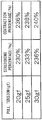
- the table shown in Fig. 2 shows an example of the characteristics of the elastic yarn 14.
- the pull tensions are those after extracting portions of the tensions in the range of 20 gf to 30 gf. However, actually, a wider range is measured.
- a characteristic of the elastic yarn 14 is that, due to the effects of hysteresis, the elastic yarn 14 that is stretched once is not restored to its original length. Therefore, as can be understood from Fig. 2 , even if the pull tension is the same, the stretching percentage when the elastic yarn 14 stretches and the contraction percentage when the elastic yarn 14 contracts differ from each other.
- Fig. 1 it is possible to acquire the yarn characteristics at the knitting machine by providing a jig to which the elastic yarn 14 is fixed at a location upstream from the tension sensor 46, fixing the elastic yarn 14 to the jig, driving the driving roller 30 of the sending-out mechanism 34 in this state, measuring the tension while drawing out the elastic yarn 14, and then measuring the tension while winding back the elastic yarn 14.
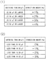
- Fig. 3(1) shows a table showing an example of the contraction parameter 52.
- the table shows correction amounts of the sending-out mechanism 34 for corresponding ranges of entering tensions considering the contraction percentages when the elastic yarn 14 contracts from the characteristics of the elastic yarn 14 shown in Fig. 2 .
- the contraction parameter 52 is used when the entering tension of the elastic yarn 14 that is detected by the tension sensor 46 is larger than the knitting tension provided by the buffer arm 40. That is, after the elastic yarn 14 has been sent out by the sending-out mechanism 34, the tension that is applied to the elastic yarn 14 is reduced and the elastic yarn 14 contracts.
- the contraction parameter 52 is used to perform correction such that the sending-out mechanism 34 acts on a plus side, so that the sending-out amount of the elastic yarn 14 is increased.
- the sending-out mechanism 34 is controlled so as to send out an elastic yarn 14 having a length of 8.16 mm.
- Fig. 3(2) shows a table showing an example of the stretching parameter 54.
- This table shows correction amounts of the sending-out mechanism 34 for corresponding ranges of entering tensions considering the stretching percentages when the elastic yarn 14 stretches from the characteristics of the elastic yarn 14 shown in Fig. 2 .
- the stretching parameter 54 is used when the entering tension of the elastic yarn 14 that is detected by the tension sensor 46 is smaller than the knitting tension provided by the buffer arm 40. That is, after the elastic yarn 14 has been sent out by the sending-out mechanism 34, the tension that is applied to the elastic yarn 14 is increased and the elastic yarn 14 stretches.
- the stretching parameter 54 is used to perform correction such that the sending-out mechanism 34 acts on a negative side, so that the sending-out amount of the elastic yarn 14 is decreased.
- the sending-out mechanism 34 is controlled so as to send out an elastic yarn 14 having a length of 7.84 mm.
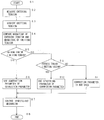
- Fig. 4 shows a flowchart of a feeding process of the elastic yarn 14 during a knitting operation.
- Step S2 an entering tension before the elastic yarn 14 enters the sending-out mechanism 34 is measured by using the tension sensor 46.
- the tension sensor 46 measures the tension of the elastic yarn 14 for, for example, every 1 ms in a predetermined zone of a knit course. When the measurement of the tension in the predetermined zone is completed, the average tension in this zone is calculated. This makes it possible to acquire an entering tension with high precision.
- a predetermined zone of knit course may be for one course.
- the tension of the elastic yarn 14 in a knitting-in zone and a knitting-out zone is not stable, it is desirable that, for example, a location excluding the knitting-in zone and the knitting-out zone be the predetermined zone. It is possible to more stably perform a knitting operation by determining the average value of tensions determined in such a predetermined zone for, for example, two to three courses, and averaging these tension values.
- the measurement of the entering tension and the determination of the correction amount by the correction amount determining means 48 are performed when a knit product is actually knitted.
- the measurement of the entering tension and the determination of the correction amount by the correction amount determining means 48 are also performed when a loop length routine is executed in order to perform stitch cam adjustment before the actual knitting operation, it is possible to correct the feeding amount from a first course during the actual knitting operation.
- Step S3 the knitting tension is acquired.
- the knitting tension is determined by the torque that is applied to the buffer arm 40 by the torque generator 38.
- the torque that is applied to the buffer arm 40 is set such that the knitting tension is fixed at, for example, 20 gf or 25 gf.
- the knitting tension may be determined in accordance with the characteristics of the elastic yarn 14 that is used and the knit product to be knitted. Instead of being fixed, the knitting tension may be variable in accordance with, for example, a knitting-in location, a knitting-out location, or a knitting location.
- Step S4 the magnitude of the entering tension in Step S2 and the magnitude of the knitting tension in Step S3 are compared with each other.
- Step S5 if the entering tension is larger than the knitting tension, the process proceeds to Step S6.
- Step S6 when the elastic yarn 14 moves past the sending-out mechanism 34, the tension is decreased and, thus, the elastic yarn 14 contracts. Therefore, the correction amount determining means 48 uses the contraction parameter 52 of the correction parameter 50, and determines the correction amount of the sending-out mechanism 34 that is appropriate for the entering tension. Then, the process proceeds to Step S7 and the controlling means 36 controls the sending-out mechanism 34 by the determined correction amount.
- Step S9 if the entering tension is smaller than the knitting tension, the process proceeds to Step S10.
- Step S10 when the elastic yarn 14 moves past the sending-out mechanism 34, the tension is increased and, thus, the elastic yarn 14 stretches. Therefore, the correction amount determining means 48 uses the stretching parameter 54 of the correction parameter 50, and determines the correction amount of the sending-out mechanism 34 that is appropriate for the entering tension. Then, the process proceeds to Step S7 and the controlling means 36 controls the sending-out mechanism 34 by the determined correction amount.
- Step S11 when the entering tension and the knitting tension are the same, the correction parameter 50 does not need to be particularly used. Then, the process proceeds to Step S7, and the sending-out mechanism 34 is controlled without any correction. Lastly, the process proceeds to Step S8 and the process ends.
- the angular displacement of the buffer arm 40 can be detected by the angle sensor 44.
- the angle sensor 44 On the basis of the difference between the angle of the buffer arm 40 before the knitting of one course and the angle of the buffer arm 40 after the knitting of one course, it is possible to determine an error between a theoretical value of the amount of elastic yarn 14 that is used for the one course and the actual amount of elastic yarn 14 that is used.
- the angle of the buffer arm 40 before the knitting of one course can match a predetermined angle by drawing out or winding back the elastic yarn 14 by the sending-out mechanism 34.
- the error of the yarn amount with respect to the theoretical value is calculated, and the density is corrected such that this error can be absorbed in the next course. This makes it possible to bring the length of the elastic yarn 14 even closer to the theoretical value.
- correction amount determining means 48 compares an entering tension of an elastic yarn 14 measured by a tension sensor 46 and a knitting tension provided by the buffer arm 40, and determines a correction amount of the control of the torque of the buffer arm 40 such that the difference between the entering tension and the knitting tension is small.
- the controlling means 36 controls the torque generator 38 to control the torque of the buffer arm 40.
- the knitting tension changes for each course, it is not desirable that the torque of the buffer arm 40 be considerably changed.
- the correction amount determining means 48 compares the entering tension and the knitting tension with each other, and determines the correction amount for controlling the sending-out mechanism 34. In this case, it is possible to decrease the correction amounts of both the control of the torque of the buffer arm 40 and the control of the feeding of the sending-out mechanism 34.
Landscapes
- Engineering & Computer Science (AREA)
- Textile Engineering (AREA)
- Knitting Machines (AREA)
- Braiding, Manufacturing Of Bobbin-Net Or Lace, And Manufacturing Of Nets By Knotting (AREA)
Applications Claiming Priority (1)
| Application Number | Priority Date | Filing Date | Title |
|---|---|---|---|
| JP2017092655A JP6498232B2 (ja) | 2017-05-08 | 2017-05-08 | 横編機における弾性糸の糸送り装置 |
Publications (2)
| Publication Number | Publication Date |
|---|---|
| EP3401428A1 true EP3401428A1 (de) | 2018-11-14 |
| EP3401428B1 EP3401428B1 (de) | 2020-06-10 |
Family
ID=62134133
Family Applications (1)
| Application Number | Title | Priority Date | Filing Date |
|---|---|---|---|
| EP18171107.8A Active EP3401428B1 (de) | 2017-05-08 | 2018-05-07 | Fadenzuführvorrichtung für elastisches garn für eine flachstrickmaschine |
Country Status (4)
| Country | Link |
|---|---|
| EP (1) | EP3401428B1 (de) |
| JP (1) | JP6498232B2 (de) |
| KR (1) | KR101954658B1 (de) |
| CN (1) | CN108866785B (de) |
Families Citing this family (5)
| Publication number | Priority date | Publication date | Assignee | Title |
|---|---|---|---|---|
| CN110760989B (zh) * | 2019-11-08 | 2021-01-26 | 西安工程大学 | 一种横机氨纶纱线控制器 |
| CN111607890B (zh) * | 2020-05-29 | 2022-02-15 | 江南大学 | 一种裸氨丝添纱横编针织物的织造方法及其纱线喂入装置 |
| CN113584704B (zh) * | 2021-08-20 | 2022-12-02 | 针知运纺织科技(上海)有限公司 | 一种电脑横编针织机衬纬纱导纱系统 |
| CN114164551A (zh) * | 2021-12-16 | 2022-03-11 | 桐乡市桐诚科技有限公司 | 一种电脑横机送纱检测装置及其送纱控制方法 |
| USD1079760S1 (en) | 2024-08-20 | 2025-06-17 | Esten Morgan | Tensioning adapter |
Citations (4)
| Publication number | Priority date | Publication date | Assignee | Title |
|---|---|---|---|---|
| JP2541574B2 (ja) | 1986-08-16 | 1996-10-09 | メミンガー―イロ ゲゼルシャフト ミット ベシュレンクテル ハフツング | 電子的糸張力制御機能を有する給糸装置 |
| EP1548163A1 (de) * | 2002-07-24 | 2005-06-29 | Shima Seiki Manufacturing Limited | Garnzuf hrer f r flachstrickmaschine |
| EP1626113A1 (de) * | 2003-04-18 | 2006-02-15 | Shima Seiki Manufacturing, Ltd. | Kulierstrick- oder kulierwirkverfahren und -system mit elastischem garn |
| EP2251470A1 (de) * | 2008-03-07 | 2010-11-17 | Shima Seiki Mfg., Ltd | Vorrichtung und verfahren zum stricken eines stoffes mit elastischen garnen |
Family Cites Families (4)
| Publication number | Priority date | Publication date | Assignee | Title |
|---|---|---|---|---|
| WO1997013904A1 (en) * | 1995-10-12 | 1997-04-17 | E.I. Du Pont De Nemours And Company | Process and apparatus for knitting fabric with non-elastic yarn and bare elastomeric yarn and sweater knit fabric construction |
| JP3603031B2 (ja) | 2001-01-31 | 2004-12-15 | 株式会社島精機製作所 | 給糸装置 |
| JP5161093B2 (ja) | 2006-09-15 | 2013-03-13 | 株式会社島精機製作所 | 編糸の弾性特性測定方法および編機 |
| JP5963393B2 (ja) | 2008-08-22 | 2016-08-03 | 株式会社島精機製作所 | 横編機 |
-
2017
- 2017-05-08 JP JP2017092655A patent/JP6498232B2/ja active Active
-
2018
- 2018-05-03 KR KR1020180051112A patent/KR101954658B1/ko active Active
- 2018-05-07 EP EP18171107.8A patent/EP3401428B1/de active Active
- 2018-05-07 CN CN201810425310.6A patent/CN108866785B/zh active Active
Patent Citations (5)
| Publication number | Priority date | Publication date | Assignee | Title |
|---|---|---|---|---|
| JP2541574B2 (ja) | 1986-08-16 | 1996-10-09 | メミンガー―イロ ゲゼルシャフト ミット ベシュレンクテル ハフツング | 電子的糸張力制御機能を有する給糸装置 |
| EP1548163A1 (de) * | 2002-07-24 | 2005-06-29 | Shima Seiki Manufacturing Limited | Garnzuf hrer f r flachstrickmaschine |
| JP4016030B2 (ja) | 2002-07-24 | 2007-12-05 | 株式会社島精機製作所 | 横編機の給糸装置 |
| EP1626113A1 (de) * | 2003-04-18 | 2006-02-15 | Shima Seiki Manufacturing, Ltd. | Kulierstrick- oder kulierwirkverfahren und -system mit elastischem garn |
| EP2251470A1 (de) * | 2008-03-07 | 2010-11-17 | Shima Seiki Mfg., Ltd | Vorrichtung und verfahren zum stricken eines stoffes mit elastischen garnen |
Also Published As
| Publication number | Publication date |
|---|---|
| EP3401428B1 (de) | 2020-06-10 |
| KR101954658B1 (ko) | 2019-03-06 |
| CN108866785B (zh) | 2020-04-10 |
| JP2018188771A (ja) | 2018-11-29 |
| KR20180123442A (ko) | 2018-11-16 |
| CN108866785A (zh) | 2018-11-23 |
| JP6498232B2 (ja) | 2019-04-10 |
Similar Documents
| Publication | Publication Date | Title |
|---|---|---|
| EP3401428B1 (de) | Fadenzuführvorrichtung für elastisches garn für eine flachstrickmaschine | |
| JP4637981B2 (ja) | 繊維機械と、繊維機械に供給する糸の供給を制御する装置とからなる構成 | |
| JP2009173445A5 (de) | ||
| KR100955809B1 (ko) | 횡편기의 급사장치 | |
| RU2004133029A (ru) | Способ подачи нити к текстильной машине и устройство для его осуществления | |
| EP2573026A1 (de) | Fadenzufuhrsystem | |
| JPWO2010021151A1 (ja) | 横編機 | |
| JPH01124675A (ja) | ウエブ用の仕上げ兼収縮装置およびその運転法 | |
| KR101541317B1 (ko) | 탄성사 사용의 편성포 편성장치 및 방법 | |
| EP1715091B1 (de) | Verfahren und Vorrichtung zum Rundstricken eines Elastomergarns mit Kompensierung der Garnkörperrelaxation | |
| US8249739B2 (en) | Yarn feeding device and yarn feeding method for knitting machine | |
| EP2573027B1 (de) | Kalibrierverfahren für Garnzuführer mit geregelter Spannung in Webzeilen | |
| JPH06272141A (ja) | 編み地制御装置 | |
| EP3754078B1 (de) | Einrichtverfahren von spannvorrichtungen auf einer flachstrickmaschine und einrichtungssystem | |
| JP7462459B2 (ja) | 横編機の天バネ装置の設定方法及び設定システム |
Legal Events
| Date | Code | Title | Description |
|---|---|---|---|
| PUAI | Public reference made under article 153(3) epc to a published international application that has entered the european phase |
Free format text: ORIGINAL CODE: 0009012 |
|
| STAA | Information on the status of an ep patent application or granted ep patent |
Free format text: STATUS: THE APPLICATION HAS BEEN PUBLISHED |
|
| AK | Designated contracting states |
Kind code of ref document: A1 Designated state(s): AL AT BE BG CH CY CZ DE DK EE ES FI FR GB GR HR HU IE IS IT LI LT LU LV MC MK MT NL NO PL PT RO RS SE SI SK SM TR |
|
| AX | Request for extension of the european patent |
Extension state: BA ME |
|
| STAA | Information on the status of an ep patent application or granted ep patent |
Free format text: STATUS: REQUEST FOR EXAMINATION WAS MADE |
|
| 17P | Request for examination filed |
Effective date: 20190509 |
|
| RBV | Designated contracting states (corrected) |
Designated state(s): AL AT BE BG CH CY CZ DE DK EE ES FI FR GB GR HR HU IE IS IT LI LT LU LV MC MK MT NL NO PL PT RO RS SE SI SK SM TR |
|
| GRAJ | Information related to disapproval of communication of intention to grant by the applicant or resumption of examination proceedings by the epo deleted |
Free format text: ORIGINAL CODE: EPIDOSDIGR1 |
|
| STAA | Information on the status of an ep patent application or granted ep patent |
Free format text: STATUS: GRANT OF PATENT IS INTENDED |
|
| RIC1 | Information provided on ipc code assigned before grant |
Ipc: D04B 15/50 20060101AFI20191127BHEP |
|
| GRAP | Despatch of communication of intention to grant a patent |
Free format text: ORIGINAL CODE: EPIDOSNIGR1 |
|
| INTG | Intention to grant announced |
Effective date: 20200103 |
|
| RAP1 | Party data changed (applicant data changed or rights of an application transferred) |
Owner name: SHIMA SEIKI MFG., LTD. |
|
| RIN1 | Information on inventor provided before grant (corrected) |
Inventor name: KOMURA, YOSHIYUKI |
|
| GRAS | Grant fee paid |
Free format text: ORIGINAL CODE: EPIDOSNIGR3 |
|
| GRAA | (expected) grant |
Free format text: ORIGINAL CODE: 0009210 |
|
| STAA | Information on the status of an ep patent application or granted ep patent |
Free format text: STATUS: THE PATENT HAS BEEN GRANTED |
|
| AK | Designated contracting states |
Kind code of ref document: B1 Designated state(s): AL AT BE BG CH CY CZ DE DK EE ES FI FR GB GR HR HU IE IS IT LI LT LU LV MC MK MT NL NO PL PT RO RS SE SI SK SM TR |
|
| REG | Reference to a national code |
Ref country code: GB Ref legal event code: FG4D |
|
| REG | Reference to a national code |
Ref country code: CH Ref legal event code: EP Ref country code: AT Ref legal event code: REF Ref document number: 1279267 Country of ref document: AT Kind code of ref document: T Effective date: 20200615 |
|
| REG | Reference to a national code |
Ref country code: DE Ref legal event code: R096 Ref document number: 602018005148 Country of ref document: DE |
|
| REG | Reference to a national code |
Ref country code: IE Ref legal event code: FG4D |
|
| REG | Reference to a national code |
Ref country code: LT Ref legal event code: MG4D |
|
| PG25 | Lapsed in a contracting state [announced via postgrant information from national office to epo] |
Ref country code: SE Free format text: LAPSE BECAUSE OF FAILURE TO SUBMIT A TRANSLATION OF THE DESCRIPTION OR TO PAY THE FEE WITHIN THE PRESCRIBED TIME-LIMIT Effective date: 20200610 Ref country code: FI Free format text: LAPSE BECAUSE OF FAILURE TO SUBMIT A TRANSLATION OF THE DESCRIPTION OR TO PAY THE FEE WITHIN THE PRESCRIBED TIME-LIMIT Effective date: 20200610 Ref country code: NO Free format text: LAPSE BECAUSE OF FAILURE TO SUBMIT A TRANSLATION OF THE DESCRIPTION OR TO PAY THE FEE WITHIN THE PRESCRIBED TIME-LIMIT Effective date: 20200910 Ref country code: GR Free format text: LAPSE BECAUSE OF FAILURE TO SUBMIT A TRANSLATION OF THE DESCRIPTION OR TO PAY THE FEE WITHIN THE PRESCRIBED TIME-LIMIT Effective date: 20200911 Ref country code: LT Free format text: LAPSE BECAUSE OF FAILURE TO SUBMIT A TRANSLATION OF THE DESCRIPTION OR TO PAY THE FEE WITHIN THE PRESCRIBED TIME-LIMIT Effective date: 20200610 |
|
| REG | Reference to a national code |
Ref country code: NL Ref legal event code: MP Effective date: 20200610 |
|
| PG25 | Lapsed in a contracting state [announced via postgrant information from national office to epo] |
Ref country code: BG Free format text: LAPSE BECAUSE OF FAILURE TO SUBMIT A TRANSLATION OF THE DESCRIPTION OR TO PAY THE FEE WITHIN THE PRESCRIBED TIME-LIMIT Effective date: 20200910 Ref country code: LV Free format text: LAPSE BECAUSE OF FAILURE TO SUBMIT A TRANSLATION OF THE DESCRIPTION OR TO PAY THE FEE WITHIN THE PRESCRIBED TIME-LIMIT Effective date: 20200610 Ref country code: RS Free format text: LAPSE BECAUSE OF FAILURE TO SUBMIT A TRANSLATION OF THE DESCRIPTION OR TO PAY THE FEE WITHIN THE PRESCRIBED TIME-LIMIT Effective date: 20200610 Ref country code: HR Free format text: LAPSE BECAUSE OF FAILURE TO SUBMIT A TRANSLATION OF THE DESCRIPTION OR TO PAY THE FEE WITHIN THE PRESCRIBED TIME-LIMIT Effective date: 20200610 |
|
| REG | Reference to a national code |
Ref country code: AT Ref legal event code: MK05 Ref document number: 1279267 Country of ref document: AT Kind code of ref document: T Effective date: 20200610 |
|
| PG25 | Lapsed in a contracting state [announced via postgrant information from national office to epo] |
Ref country code: NL Free format text: LAPSE BECAUSE OF FAILURE TO SUBMIT A TRANSLATION OF THE DESCRIPTION OR TO PAY THE FEE WITHIN THE PRESCRIBED TIME-LIMIT Effective date: 20200610 Ref country code: AL Free format text: LAPSE BECAUSE OF FAILURE TO SUBMIT A TRANSLATION OF THE DESCRIPTION OR TO PAY THE FEE WITHIN THE PRESCRIBED TIME-LIMIT Effective date: 20200610 |
|
| PG25 | Lapsed in a contracting state [announced via postgrant information from national office to epo] |
Ref country code: EE Free format text: LAPSE BECAUSE OF FAILURE TO SUBMIT A TRANSLATION OF THE DESCRIPTION OR TO PAY THE FEE WITHIN THE PRESCRIBED TIME-LIMIT Effective date: 20200610 Ref country code: SM Free format text: LAPSE BECAUSE OF FAILURE TO SUBMIT A TRANSLATION OF THE DESCRIPTION OR TO PAY THE FEE WITHIN THE PRESCRIBED TIME-LIMIT Effective date: 20200610 Ref country code: AT Free format text: LAPSE BECAUSE OF FAILURE TO SUBMIT A TRANSLATION OF THE DESCRIPTION OR TO PAY THE FEE WITHIN THE PRESCRIBED TIME-LIMIT Effective date: 20200610 Ref country code: PT Free format text: LAPSE BECAUSE OF FAILURE TO SUBMIT A TRANSLATION OF THE DESCRIPTION OR TO PAY THE FEE WITHIN THE PRESCRIBED TIME-LIMIT Effective date: 20201012 Ref country code: RO Free format text: LAPSE BECAUSE OF FAILURE TO SUBMIT A TRANSLATION OF THE DESCRIPTION OR TO PAY THE FEE WITHIN THE PRESCRIBED TIME-LIMIT Effective date: 20200610 Ref country code: CZ Free format text: LAPSE BECAUSE OF FAILURE TO SUBMIT A TRANSLATION OF THE DESCRIPTION OR TO PAY THE FEE WITHIN THE PRESCRIBED TIME-LIMIT Effective date: 20200610 Ref country code: ES Free format text: LAPSE BECAUSE OF FAILURE TO SUBMIT A TRANSLATION OF THE DESCRIPTION OR TO PAY THE FEE WITHIN THE PRESCRIBED TIME-LIMIT Effective date: 20200610 |
|
| PG25 | Lapsed in a contracting state [announced via postgrant information from national office to epo] |
Ref country code: SK Free format text: LAPSE BECAUSE OF FAILURE TO SUBMIT A TRANSLATION OF THE DESCRIPTION OR TO PAY THE FEE WITHIN THE PRESCRIBED TIME-LIMIT Effective date: 20200610 Ref country code: PL Free format text: LAPSE BECAUSE OF FAILURE TO SUBMIT A TRANSLATION OF THE DESCRIPTION OR TO PAY THE FEE WITHIN THE PRESCRIBED TIME-LIMIT Effective date: 20200610 Ref country code: IS Free format text: LAPSE BECAUSE OF FAILURE TO SUBMIT A TRANSLATION OF THE DESCRIPTION OR TO PAY THE FEE WITHIN THE PRESCRIBED TIME-LIMIT Effective date: 20201010 |
|
| REG | Reference to a national code |
Ref country code: DE Ref legal event code: R097 Ref document number: 602018005148 Country of ref document: DE |
|
| PLBE | No opposition filed within time limit |
Free format text: ORIGINAL CODE: 0009261 |
|
| STAA | Information on the status of an ep patent application or granted ep patent |
Free format text: STATUS: NO OPPOSITION FILED WITHIN TIME LIMIT |
|
| PG25 | Lapsed in a contracting state [announced via postgrant information from national office to epo] |
Ref country code: DK Free format text: LAPSE BECAUSE OF FAILURE TO SUBMIT A TRANSLATION OF THE DESCRIPTION OR TO PAY THE FEE WITHIN THE PRESCRIBED TIME-LIMIT Effective date: 20200610 |
|
| 26N | No opposition filed |
Effective date: 20210311 |
|
| PG25 | Lapsed in a contracting state [announced via postgrant information from national office to epo] |
Ref country code: SI Free format text: LAPSE BECAUSE OF FAILURE TO SUBMIT A TRANSLATION OF THE DESCRIPTION OR TO PAY THE FEE WITHIN THE PRESCRIBED TIME-LIMIT Effective date: 20200610 |
|
| REG | Reference to a national code |
Ref country code: CH Ref legal event code: PL |
|
| PG25 | Lapsed in a contracting state [announced via postgrant information from national office to epo] |
Ref country code: CH Free format text: LAPSE BECAUSE OF NON-PAYMENT OF DUE FEES Effective date: 20210531 Ref country code: MC Free format text: LAPSE BECAUSE OF FAILURE TO SUBMIT A TRANSLATION OF THE DESCRIPTION OR TO PAY THE FEE WITHIN THE PRESCRIBED TIME-LIMIT Effective date: 20200610 Ref country code: LU Free format text: LAPSE BECAUSE OF NON-PAYMENT OF DUE FEES Effective date: 20210507 Ref country code: LI Free format text: LAPSE BECAUSE OF NON-PAYMENT OF DUE FEES Effective date: 20210531 |
|
| REG | Reference to a national code |
Ref country code: BE Ref legal event code: MM Effective date: 20210531 |
|
| PG25 | Lapsed in a contracting state [announced via postgrant information from national office to epo] |
Ref country code: IE Free format text: LAPSE BECAUSE OF NON-PAYMENT OF DUE FEES Effective date: 20210507 |
|
| PG25 | Lapsed in a contracting state [announced via postgrant information from national office to epo] |
Ref country code: FR Free format text: LAPSE BECAUSE OF NON-PAYMENT OF DUE FEES Effective date: 20210531 |
|
| PG25 | Lapsed in a contracting state [announced via postgrant information from national office to epo] |
Ref country code: BE Free format text: LAPSE BECAUSE OF NON-PAYMENT OF DUE FEES Effective date: 20210531 |
|
| GBPC | Gb: european patent ceased through non-payment of renewal fee |
Effective date: 20220507 |
|
| PG25 | Lapsed in a contracting state [announced via postgrant information from national office to epo] |
Ref country code: GB Free format text: LAPSE BECAUSE OF NON-PAYMENT OF DUE FEES Effective date: 20220507 |
|
| PG25 | Lapsed in a contracting state [announced via postgrant information from national office to epo] |
Ref country code: CY Free format text: LAPSE BECAUSE OF FAILURE TO SUBMIT A TRANSLATION OF THE DESCRIPTION OR TO PAY THE FEE WITHIN THE PRESCRIBED TIME-LIMIT Effective date: 20200610 |
|
| PG25 | Lapsed in a contracting state [announced via postgrant information from national office to epo] |
Ref country code: HU Free format text: LAPSE BECAUSE OF FAILURE TO SUBMIT A TRANSLATION OF THE DESCRIPTION OR TO PAY THE FEE WITHIN THE PRESCRIBED TIME-LIMIT; INVALID AB INITIO Effective date: 20180507 |
|
| PG25 | Lapsed in a contracting state [announced via postgrant information from national office to epo] |
Ref country code: MK Free format text: LAPSE BECAUSE OF FAILURE TO SUBMIT A TRANSLATION OF THE DESCRIPTION OR TO PAY THE FEE WITHIN THE PRESCRIBED TIME-LIMIT Effective date: 20200610 |
|
| PG25 | Lapsed in a contracting state [announced via postgrant information from national office to epo] |
Ref country code: MT Free format text: LAPSE BECAUSE OF FAILURE TO SUBMIT A TRANSLATION OF THE DESCRIPTION OR TO PAY THE FEE WITHIN THE PRESCRIBED TIME-LIMIT Effective date: 20200610 |
|
| PGFP | Annual fee paid to national office [announced via postgrant information from national office to epo] |
Ref country code: DE Payment date: 20250311 Year of fee payment: 8 |
|
| PGFP | Annual fee paid to national office [announced via postgrant information from national office to epo] |
Ref country code: IT Payment date: 20250422 Year of fee payment: 8 |
|
| PG25 | Lapsed in a contracting state [announced via postgrant information from national office to epo] |
Ref country code: TR Free format text: LAPSE BECAUSE OF FAILURE TO SUBMIT A TRANSLATION OF THE DESCRIPTION OR TO PAY THE FEE WITHIN THE PRESCRIBED TIME-LIMIT Effective date: 20200610 |