EP3754078B1 - Einrichtverfahren von spannvorrichtungen auf einer flachstrickmaschine und einrichtungssystem - Google Patents
Einrichtverfahren von spannvorrichtungen auf einer flachstrickmaschine und einrichtungssystem Download PDFInfo
- Publication number
- EP3754078B1 EP3754078B1 EP20180428.3A EP20180428A EP3754078B1 EP 3754078 B1 EP3754078 B1 EP 3754078B1 EP 20180428 A EP20180428 A EP 20180428A EP 3754078 B1 EP3754078 B1 EP 3754078B1
- Authority
- EP
- European Patent Office
- Prior art keywords
- yarn
- tension
- yarn feeding
- knitting machine
- flat knitting
- Prior art date
- Legal status (The legal status is an assumption and is not a legal conclusion. Google has not performed a legal analysis and makes no representation as to the accuracy of the status listed.)
- Active
Links
Images
Classifications
-
- D—TEXTILES; PAPER
- D04—BRAIDING; LACE-MAKING; KNITTING; TRIMMINGS; NON-WOVEN FABRICS
- D04B—KNITTING
- D04B15/00—Details of, or auxiliary devices incorporated in, weft knitting machines, restricted to machines of this kind
- D04B15/38—Devices for supplying, feeding, or guiding threads to needles
- D04B15/44—Tensioning devices for individual threads
-
- D—TEXTILES; PAPER
- D04—BRAIDING; LACE-MAKING; KNITTING; TRIMMINGS; NON-WOVEN FABRICS
- D04B—KNITTING
- D04B15/00—Details of, or auxiliary devices incorporated in, weft knitting machines, restricted to machines of this kind
- D04B15/38—Devices for supplying, feeding, or guiding threads to needles
- D04B15/54—Thread guides
- D04B15/56—Thread guides for flat-bed knitting machines
-
- D—TEXTILES; PAPER
- D04—BRAIDING; LACE-MAKING; KNITTING; TRIMMINGS; NON-WOVEN FABRICS
- D04B—KNITTING
- D04B15/00—Details of, or auxiliary devices incorporated in, weft knitting machines, restricted to machines of this kind
- D04B15/94—Driving-gear not otherwise provided for
- D04B15/99—Driving-gear not otherwise provided for electrically controlled
-
- D—TEXTILES; PAPER
- D04—BRAIDING; LACE-MAKING; KNITTING; TRIMMINGS; NON-WOVEN FABRICS
- D04B—KNITTING
- D04B35/00—Details of, or auxiliary devices incorporated in, knitting machines, not otherwise provided for
- D04B35/10—Indicating, warning, or safety devices, e.g. stop motions
- D04B35/12—Indicating, warning, or safety devices, e.g. stop motions responsive to thread consumption
Definitions
- the invention relates to the setup of top tension devices on a flat knitting machine.
- top tension devices upper tensioning biasing devices
- a flat knitting machine has, for example, about twenty top tension devices, and therefore, a knitting shop having a large number of flat knitting machines has a considerably large number of top tension devices.
- tension can be applied to a yarn controllably.
- a disc cramps a yarn and when the pressure from the disc to the yarn is controlled, the tension is controlled.
- rollers of a yarn are driven by a motor and when the torque applied to the rollers is controlled, the tension can be controlled.
- the pressure from the disc or the torque to the rollers is made constant, different yarns make the applied tension change.
- the suitable tension to be applied by a top tension device is dependent upon and changes according to a yarn feeding route to a carrier for the yarn. Further, the yarn feeding routes change according to respective top tension devices. Therefore, it is troublesome to set tension for a large number of top tension devices.
- Patent Document 1 JP H08-3844A
- Prior art document US 2006/01848267 A1 discloses a yarn feeder system which includes a plurality of yarn feeders combined into one group.
- the yarn feeders operate in an individually tension-controlled manner on the basis of a specified yarn tension value.
- the yarn feed quantities or yarn speeds that result from this at the various yarn feeders are reported to a central unit. From the reported yarn speeds, the central unit calculates a group average and sends this to the yarn feeders as a specified value for subsequent operation.
- a method and a system for managing and controlling the feeding of at least one thread to a textile machine as a function of the operating step of the latter in the production of a product or in the processing of such thread, such production or processing providing for a succession of said steps corresponding to the obtainment of various parts of the same product or different treatments of such thread, the latter being fed to said machine by a corresponding feeder device at a constant tension and/or speed and/or controlled by a sensor which monitors the sliding or any of the inherent characteristics thereof such as tension, speed, diameter, quantity and color, said sensor and/or feeder being controlled by setting and control means which set the operation thereof, said setting and control means receiving synchronization signals from the machine and detecting - according to the latter - the aforementioned operating steps and thus the processing progress status of a product or production process, said setting of the operation being programmed as a function of said operating steps.
- the object of the invention is to set tension automatically for top tension devices that apply electrically controllably tension to yarns.
- the setup of the torque is automatically changed.
- the invention is particularly efficient when a large number of the top tension devices are used.
- yarns of the same species may be regarded as the same yarn, however, there are cases where the same species of yarns have different characteristics due to changes in the temperature, humidity, and the production lot. In such cases, when temperature, humidity, or the production lot changes, it is preferable to measure the input value to the adjusting member once more.
- said input value is corrected based on a species of a yarn feeding object to which said each yarn is fed by the top tension device at an upper stream position of the carrier along a direction of yarn feeding, the number of eyelets (yarn guide) which said each yarn passes through in said each yarn feeding route, and the degree of bending of said each yarn in said each yarn feeding route.
- the tension to be applied by the top tension device is dependent upon the yarn feeding route.
- the input value is corrected according to the elements in the yarn feeding route and may be transformed to the setup value.
- said input value is measured for each of plural yarn feeding speeds, and the controller of the flat knitting machine corrects the setup value during knitting, based upon the yarn feeding speed from the top tension device.
- the controller of the flat knitting machine corrects the setup value during knitting, based upon the yarn feeding speed from the top tension device.
- said each yarn is fed through the adjusting member and a tension sensor to a drawing member, the adjusting member applies tension to said each yarn, the drawing member draws said each yarn, and the input value to the adjusting member is measured when the tension applied to said each yarn, measured by the tension sensor, is a desired value.
- the input value can be measured without using a flat knitting machine, as defined in claim 1. And therefore, knitting machines have not to be halted during the measurement. Therefore, knitted fabrics are produced more efficiently.
- the tension sensor is provided between the top tension device and a side tension device, a positive yarn feeding device, or the like, the drawing member is provided at a downstream position of the carrier, and then, the input value to the adjusting member can be measured on a flat knitting machine and without actual knitting, as defined in claim 3.
- a correction amount for each element in the yarn feeding route is retrieved and added.
- a correction amount for the entire yarn feeding route may be measured.
- This correction is also a correction corresponding to elements in the yarn feeding route.
- the drawing speed of the yarn and the tension in the vicinity of the outlet of the top tension device are made constant, and the necessary input value to the adjusting member is measured for each yarn feeding route.
- the difference from an input value to a standard top tension device is stored as a correction amount for each yarn feeding route. Even when the species of the yarn is changed, this correction amount for each yarn feeding route is usable, for example, without alteration.
- Figs. 1 to 5 indicate an embodiment.
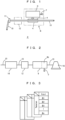
- Fig. 1 indicates an example of the top tension device 2; indicated by 4 are a pair of dies that cramp a yarn and apply pressure.
- Indicated by 6 is a driver for driving the dies 4 so as to adjust the pressure
- indicated by 7 is an input port for inputting an electrical input to the driver 6.
- the whole from the dies 4 to the port 7 are referred to as an adjusting member 8.
- the yarn 10 may be braked by rollers in contact with the yarn, and the mechanism for the tension adjustment is arbitrary.
- indicated by 11 is an eyelet for guiding the yarn.
- a tension sensor 12 is provided in the top tension device 2, input values to an adjusting member shown in Fig. 2 can be measured.
- the tension sensors may be provided in a part of the top tension devices 2, when the sensors are provided.
- the correction amounts corresponding to elements in the yarn feeding route used in the measurement are subtracted, and correction amounts corresponding to the elements in the yarn feeding route for each top tension device 20 are added.
- Fig. 2 indicates the measurement of input values to the adjusting member.
- a yarn 10 is supplied from a yarn source such as an yarn package 16 or the like, to a drawing member 14, through an adjusting member 9 and the tension sensor 12.
- the adjusting member 9 may be the same as the adjusting member 8 in the top tension device 2 or a similar one, such as a version having a higher precision.
- the tension sensor 12 measures the tension applied to the yarn 10.
- the drawing member 14 has a pair of rollers for cramping the yarn and draws the yarn by driving the rollers.
- the adjusting member 9, the tension sensor 12, and the drawing member 14 are an example of a dedicated measuring means. Further, the top tension device 2 in Fig.
- the measuring means 1 in combination with the tension sensor 12 is an example of the measuring means that functions as a top tension device on a flat knitting machine.
- an input value to the adjusting device 9 is measured when the tension measured by the tension sensor 12 becomes a desired value, and the measured value is stored in a memory not shown.
- data for tables 26 shown in Fig. 3 are obtained.
- One table is provided for one drawing speed of a yarn, and preferably, input values for respective desired tensions are stored for respective drawing speeds.
- the yarn may be drawn with a slight speed and the input value to the adjusting member 9 is measured when a desired tension is achieved.
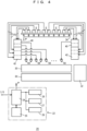
- Fig. 4 indicates setup of the top tension devices 2 on the flat knitting machine 20 according to the embodiment.
- Indicated by 30 are, for example, a pair of needle beds, and 32 is a carriage manipulating needles on the needle beds 30.
- Indicated by 34 is a stand over the needle beds 30 and supports the top tension devices 2 and yarn packages not shown.
- the top tension devices 2 draw yarns from the yarn packages, apply tension to the yarns, and supply them to the positive yarn feeding devices 40 or the side tension devices 42.
- the positive yarn feeding devices 40 and the side tension devices 42 supply the yarns to carriers 44, and the carriers 44 supply the yarns to needles on the needle beds 30.
- In the yarn feeding routes there are eyelets for changing the directions of the yarns, and therefore, the eyelets apply friction to the yarns.
- the flat knitting machine 20 is provided with a controller 22. Indicated by 24 is the main controller, 25 is a carriage controller, and 26 to 28 are tables.
- the table 26 stores data shown in Fig. 3
- the table 27 stores elements in the yarn feeding route for each top tension device 2.
- the data with respect to the elements in the yarn feeding routes may be generated based upon the knitting data or may be inputted by a user from the controller 22.
- the table 28 stores a correction amount for each element in the yarn feeding routes. For example, it stores an additional tension amount for an eyelet in the yarn feeding routes, correction amounts on the basis of intermediate yarn feeding objects between the carriers 44 and the top tension devices 2, and correction amounts on the basis of bending angles of the yarns in the yarn feeding routes.
- Fig. 4 indicates the positive yarn feeding devices 40 and the side tension devices 42.
- the positive yarn feeding devices 40 feed yarns through a gap between a pair of rollers and control the rotation number of the rollers so as to feed desired lengths of yarns.
- the side tension devices 42 apply tension to the yarns and further work as buffers of yarns.
- the positive yarn feeding devices 40 and the side tension devices 42 are different in the suitable yarn tension to be applied from the top tension devices 2. Without the positive yarn feeding devices 40 nor the side tension devices 42, yarns may be directly supplied to the carriers 44 from the top tension devices 2. In this case, the correction amount with respect to the direct yarn feeding is stored in the table 28.
- a top tension device 2 there are plural eyelets between a top tension device 2 and a carrier 44, and the yarn is bent by the eyelets. Since the eyelets apply friction to a yarn, an additional amount of tension per eyelet is stored in the table 28. Further, when a yarn is bent at an eyelet, additional tension is necessary. Since the bending angle of a yarn at an eyelet can be considered from 180 degrees (no bending) to 90 degrees, additional amounts of tension on the basis of the bending angle are stored. For example, the additional amount is stored at 9 stages and increases by 0.4 g per 10 degrees when approaching 90 degrees.
- thick yarns increase tension loss by the eyelets and so on, it is preferable to store correction amounts on the basis of the thickness of the yarns (for example, three stages in the thickness of under 0.2 mm, down to 0.2 mm and up to 0.8 mm, and over 0.8 mm) are further stored.
- the main controller 24 calculates yarn feeding speed from the top tension devices 2 on the basis of knitting information, such as the speed of the carriage, the species of push knitting or pull knitting, and consumed loop length.
- the main controller 24 performs the following processing for each top tension device 2 in use. Retrieving elements in the yarn feeding routes from the table 27, and calculates the basic tension with reference to the table 28, according to the species of the yarn feeding object of the positive yarn feeding devices 40 or the side tension devices 42. Further with reference to the table 28, retrieving a correction amount for tension for each element, and corrects the basic tension.
- the main controller retrieves the setup value for the top tension device 2 with respect to the desired tension and sets the adjustment member 8 for the top tension device 2.
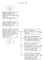
- the setup algorithm of the top tension devices according to the embodiment is shown in Fig. 5 .
- correction amounts for elements in the yarn feeding routes are determined and are stored in the table 28.
- Yarns for knitted fabrics change from a season to another season, and a large number of new species of yarns are used in one season. Therefore, data necessary for the table 26 for one species of yarn are measured by once and they are implemented to the tables 26 in plural flat knitting machines 20.
- step S 1 the input values to the adjusting member for applying desired tension to a yarn are measured for respective yarn feeding speeds and are stored.
- the ambient temperatures and humidities may change the characteristics of yarns and thus, may change the suitable input values.
- the environment where the input values to the adjusting member are measured and the environment where the flat knitting machines work it is preferable to coincide the environment where the input values to the adjusting member are measured and the environment where the flat knitting machines work.
- the characteristics of a yarn may change according to the production lot of the yarn, it is preferable to measure once more the data in the table 26 when the production lot is changed, if necessary.
- step S2 the yarn feeding routes for respective top tension devices 2 are stored in the table 27.
- the order to carry out the steps S 1 and S2 is arbitrary.
- step S3 with reference to the correction amounts stored in the table 28 and the yarn feeding routes stored in the table 27, the setup values for the adjusting members 8 in respective top tension devices 2 are determined.
- it is not necessary to perform the step S3 repeatedly during knitting. Changing amounts corresponding to yarn feeding speeds may be stored in the main controller 24 or in a table not shown, and the setup values may be changed on the basis of the changing amount corresponding to yarn feeding speeds.
- step S3 The detailed process in step S3 is indicated by steps S3a to S3d.
- step S3a the elements in the yarn feeding route are retrieved from the table 27.
- the elements in the yarn feeding route are, for example, the eyelets and the bending angle of the yarn therein, the species of the first yarn feeding object from the top tension device, such as a positive yarn feeding device or a side tension device, the direction of knitting of push knitting or pull knitting, and so on.
- step S3b correction amounts for respective elements in the yarn feeding route are retrieved from the table 28 and are added to a total correction amount.
- step S3c a subtable corresponding to the yarn feeding speed in the table 26 for each yarn is referred to, and a setup value for a desired tension is retrieved.
- the table 26 in Fig. 3 includes three subtables corresponding to three yarn feeding speeds.
- step S3d the setup value retrieved in step S3c and the total correction amount gotten in step S3b are added to the setup value of the top tension device.
- Knitting speed is frequently changed during knitting.
- steps S3a to S3d may be re-executed.
- step S3c it is preferable to re-execute only step S3c to calculate the change in the setup value from that at an old yarn feeding speed before the speed change.
- step S3c calculates the change in the setup value from that at an old yarn feeding speed before the speed change.
- a new setup value for the new yarn feeding speed is resultant.
- the direction of knitting of push knitting or pull knitting may be changed.
- the change in the correction amounts according to the direction of knitting is calculated from the table 28, and the calculated change is added to the setup value before the change in order to get a new setup value after the change.
- the data for the table 26 are enough to be measured by once for a large number of top tension devices 2, and therefore, the embodiment is very efficient.
- the invention is not needed to be carried out. However, this needs a large number of tension sensors.
- the embodiment has the following advantageous effects, in addition to the above: All top tension devices are uniformly set for a yarn to be used. Therefore, stitch sizes in knitted fabrics are made uniform between different carriers 44. Further, the stitch sizes are made uniform between flat knitting machines 2.
- Knitted fabrics with higher quality can be knitted when the setup values for tension are corrected not only on yarn feeding speeds but also on knitting start, knitting stitches at edges of a knitted fabric, the species of push knitting or pull knitting, and so on. These corrections are made by feedforward control based upon the knitting information, and the tension is kept constant without a delay resulting in feedback control.
- the stitch sizes can be positively controlled.
Landscapes
- Engineering & Computer Science (AREA)
- Textile Engineering (AREA)
- Knitting Machines (AREA)
Claims (5)
- Ein Einrichtungsverfahren für Oberspannungseinrichtungen (2), die Einstellglieder (8, 9) für das Ausüben einer elektrisch steuerbaren Spannung auf Fäden (10) aufweisen und an einer Flachstrickmaschine (20) vorgesehen sind, dadurch gekennzeichnet, dass:ein Messschritt (S1) für das Messen und Speichern eines Eingabewerts für jeden Faden (10) zu einem Einstellglied (9) für das Ausüben einer gewünschten Spannung auf jeden der Fäden (10) außerhalb der Flachstrickmaschine (20) durchgeführt wird,wobei jeder der Fäden (10) zu einem Zugglied (14) zugeführt und durch dieses durch einen Spannungssensor (12) und das Einstellglied (9) gezogen wird, wobei das Zugglied (14), der Spannungssensor (12) und das Einstellglied (9) außerhalb der Flachstrickmaschine (20) vorgesehen sind,wobei der Eingabewert zu dem Einstellglied (9) mit einer dedizierten Messeinrichtung gemessen wird, wenn die Spannung zu jedem der Fäden (10) ein gewünschter Wert ist, undwobei der Eingabewert gespeichert wird,ein Schritt (S2) zum Speichern von Elementen (11, 40, 42), die jeden der Fäden (10) in jeder Fadenführroute von einer Oberspannungseinrichtung (2) zu einem Träger (44) jedes der Fäden (10) kontaktieren oder beeinflussen und Spezies von Fadenführobjekten (40, 42) an einer stromaufwärts gelegenen Position des Trägers (44) entlang einer Fadenführrichtung, zu denen jeder der Fäden (10) durch die Oberspannungseinrichtung (2) zugeführt wird, die Anzahl von Übertragungseinrichtungen (11), durch die jeder der Fäden (10) in jeder Fadenführroute hindurchgeht, und einen Biegungsgrad jedes der Fäden (10) durch die Übertragungseinrichtungen (11) in jeder der Fadenführrouten aufweisen, durchgeführt wird, undein Einrichtungsschritt (S3) zum Korrigieren des Eingabewerts basierend auf den Elementen (11, 40, 42) für das Transformieren des Eingabewerts zu einem Einrichtungswert für die Einstellglieder (9) in jeder Fadenführroute und zum Anwenden des Einrichtungswerts auf das Einstellglied (9) in jeder Fadenführroute durch eine Steuereinrichtung (22) in der Flachstrickmaschine (20) durchgeführt wird.
- Ein Einrichtungsverfahren für Oberspannungseinrichtungen (2), die Einstellglieder (8, 9) für das Ausüben einer elektrisch steuerbaren Spannung auf Fäden (10) aufweisen und an einer Flachstrickmaschine (20) vorgesehen sind, dadurch gekennzeichnet, dass:ein Messschritt (S1) für das Messen und Speichern eines Eingabewerts für jeden Faden (10) zu einem Einstellglied (8) für das Ausüben einer gewünschten Spannung auf jeden der Fäden (10) innerhalb der Flachstrickmaschine (20) durchgeführt wird,wobei jeder der Fäden (10) zu einer Flachstrickmaschine (20) zugeführt und durch diese durch einen Spannungssensor (12) und das Einstellglied (8) gezogen wird, wobei der Spannungssensor (12) und das Einstellglied (8) an einer stromaufwärts gelegenen Position von Übertragungseinrichtungen (11) an der Flachstrickmaschine (20) vorgesehen sind,wobei der Eingabewert zu dem Einstellglied (8) mit einer dedizierten Messeinrichtung gemessen wird, wenn die Spannung des Fadens (10) ein gewünschter Wert ist, undwobei der Eingabewert gespeichert wird,ein Schritt (S2) zum Speichern von Elementen (11, 40, 42), die jeden der Fäden (10) in jeder Fadenführroute von einer Oberspannungseinrichtung (2) zu einem Träger (44) jedes der Fäden (10) kontaktieren oder beeinflussen und Spezies von Fadenführobjekten (40, 42) an einer stromaufwärts gelegenen Position des Trägers (44) entlang einer Fadenführrichtung, zu denen jeder der Fäden (10) durch die Oberspannungseinrichtung (2) zugeführt wird, die Anzahl von Übertragungseinrichtungen (11), durch die jeder der Fäden (10) in jeder Fadenführroute an stromabwärts gelegenen Positionen des Spannungssensors (12) und des Einstellglieds (8) hindurchgeht, und einen Biegungsgrad jedes der Fäden (10) durch die Übertragungseinrichtungen (11) in jeder der Fadenführrouten aufweisen, durchgeführt wird, undein Einrichtungsschritt (S3) zum Korrigieren des Eingabewerts basierend auf den Elementen (11, 40, 42) für das Transformieren des Eingabewerts zu einem Einrichtungswert für die Einstellglieder (8) in jeder Fadenführroute und zum Anwenden des Einrichtungswerts auf das Einstellglied (8) in jeder Fadenführroute durch eine Steuereinrichtung (22) in der Flachstrickmaschine (20) durchgeführt wird.
- Ein Einrichtungsverfahren für Oberspannungseinrichtungen (2), die Einstellglieder (8, 9) für das Ausüben einer elektrisch steuerbaren Spannung auf Fäden (10) aufweisen und an einer Flachstrickmaschine (20) vorgesehen sind, dadurch gekennzeichnet, dass:ein Messschritt (S1) für das Messen und Speichern eines Eingabewerts für jeden Faden (10) zu einem Einstellglied (8) für das Ausüben einer gewünschten Spannung auf jeden der Fäden (10) innerhalb der Flachstrickmaschine (20) durchgeführt wird,wobei jeder der Fäden (10) zu einem Zugglied (14) zugeführt und durch dieses durch einen Spannungssensor (12) und das Einstellglied (8) gezogen wird, wobei der Spannungssensor (12) und das Einstellglied (8) an einer stromaufwärts gelegenen Position von Übertragungseinrichtungen (11) der Flachstrickmaschine (20) vorgesehen sind und das Zugglied (14) an einer stromabwärts gelegenen Position eines Trägers der Flachstrickmaschine (20) vorgesehen ist,wobei der Eingabewert zu dem Einstellglied (8) mit einer dedizierten Messeinrichtung gemessen wird, wenn die Spannung zu jedem der Fäden (10) ein gewünschter Wert ist, undwobei der Eingabewert gespeichert wird,ein Schritt (S2) zum Speichern von Elementen (11, 40, 42), die jeden der Fäden (10) in jeder Fadenführroute von einer Oberspannungseinrichtung (2) zu einem Träger (44) jedes der Fäden (10) kontaktieren oder beeinflussen und Spezies von Fadenführobjekten (40, 42) an einer stromaufwärts gelegenen Position des Trägers (44) entlang einer Fadenführrichtung, zu denen jeder der Fäden (10) durch die Oberspannungseinrichtung (2) zugeführt wird, die Anzahl von Übertragungseinrichtungen (11), durch die jeder der Fäden (10) in jeder der Fadenführrouten an stromabwärts gelegenen Positionen des Spannungssensors (12) und des Einstellglieds (8) hindurchgeht, und einen Biegungsgrad jedes der Fäden (10) durch die Übertragungseinrichtungen (11) in jeder Fadenführroute aufweisen, durchgeführt wird, undein Einrichtungsschritt (S3) zum Korrigieren des Eingabewerts basierend auf den Elementen (11, 40, 42) für das Transformieren des Eingabewerts zu einem Einrichtungswert für das Einstellglied (8) in jeder Fadenführroute und zum Anwenden des Einrichtungswerts auf das Einstellglied (8) in jeder Fadenführroute durch eine Steuereinrichtung (22) in der Flachstrickmaschine (20) durchgeführt wird.
- Einrichtungsverfahren für Oberspannungseinrichtungen (2) nach einem der Ansprüche 1 bis 3, dadurch gekennzeichnet, dass in dem Messschritt (S1) der Eingabewert für jede von mehreren Fadenführgeschwindigkeiten gemessen wird, und gekennzeichnet durch einen Geschwindigkeitskompensationsschritt (S3c), wobei die Steuereinrichtung (22) der Flachstrickmaschine (20) den durch die Steuereinrichtung (22) berechneten Einrichtungswert während des Strickens basierend auf der Fadenführgeschwindigkeit von den Oberspannungseinrichtungen (2) korrigiert.
- Ein Einrichtungssystem für eine Flachstrickmaschine (20) mit Oberspannungseinrichtungen (2), die Einstellglieder (8, 9) für das Einstellen einer Spannung für Fäden (10) gemäß einer elektrischen Eingabe aufweisen, wobei das Einrichtungssystem aufweist:eine Messeinrichtung zum Bestimmen eines Eingabewerts für jeden Faden (10) zu dem Einstellglied (8) für das Ausüben einer gewünschten Spannung auf jeden der Fäden (10), wobei die Messeinrichtung einen Spannungssensor (12) für das Messen einer Spannung für jeden der Fäden (10) aufweist, wobei eines der an der Flachstrickmaschine (20) vorgesehenen Einstellglieder (8) und die Flachstrickmaschine (20) für das Ziehen jedes der Fäden (10) verwendet werden und wobei die Flachstrickmaschine (20) eine Steuereinrichtung (22) aufweist,wobei der Eingabewert zu dem einen der Einstellglieder (8) gemessen wird, wenn die Spannung zu jedem der Fäden (10) ein gewünschter Wert ist und wobei das Einrichtungssystem dadurch gekennzeichnet ist, dass der Spannungssensor (12) und das eine der Einstellglieder (8) an einer stromaufwärts gelegenen Position der Übertragungseinrichtungen (11) an der Flachstrickmaschine (20) vorgesehen sind, unddie Steuereinrichtung (22) der Flachstrickmaschine (20) konfiguriert ist zum Speichern des Eingabewerts und von Elementen (11, 40, 42), die die Fäden (10) in einer Fadenführroute von den Oberspannungseinrichtungen (2) zu Trägern (44) jedes der Fäden (10) kontaktieren oder beeinflussen und Spezies von Fadenführobjekten (40, 42) an einer stromaufwärts gelegenen Position der Träger (44) entlang einer Fadenführrichtung, zu denen jeder der Fäden (10) durch die Oberspannungseinrichtungen (2) zugeführt wird, die Anzahl von Übertragungseinrichtungen (11), durch die jeder der Fäden (10) in jeder der Fadenführrouten hindurchgeht, und einen Biegungsgrad jedes der Fäden (10) in jeder der Fadenführrouten aufweisen, und zum Korrigieren der Eingabewerte basierend auf den Elementen (11, 40, 42) für das Transformieren der Eingabewerte zu Einrichtungswerten für die Einstellglieder (8) und zum Anwenden des Einrichtungswerts auf die Einstellglieder (8).
Applications Claiming Priority (2)
| Application Number | Priority Date | Filing Date | Title |
|---|---|---|---|
| JP2019112504 | 2019-06-18 | ||
| JP2020068044A JP7462459B2 (ja) | 2019-06-18 | 2020-04-06 | 横編機の天バネ装置の設定方法及び設定システム |
Publications (2)
| Publication Number | Publication Date |
|---|---|
| EP3754078A1 EP3754078A1 (de) | 2020-12-23 |
| EP3754078B1 true EP3754078B1 (de) | 2024-09-11 |
Family
ID=71105324
Family Applications (1)
| Application Number | Title | Priority Date | Filing Date |
|---|---|---|---|
| EP20180428.3A Active EP3754078B1 (de) | 2019-06-18 | 2020-06-17 | Einrichtverfahren von spannvorrichtungen auf einer flachstrickmaschine und einrichtungssystem |
Country Status (3)
| Country | Link |
|---|---|
| EP (1) | EP3754078B1 (de) |
| KR (1) | KR102393871B1 (de) |
| CN (1) | CN112095217B (de) |
Family Cites Families (6)
| Publication number | Priority date | Publication date | Assignee | Title |
|---|---|---|---|---|
| JPH083844A (ja) | 1994-06-17 | 1996-01-09 | Shima Seiki Mfg Ltd | 横編機におけるテンション装置 |
| DE10234545B4 (de) * | 2002-07-30 | 2005-12-15 | Memminger-Iro Gmbh | Verfahren und Vorrichtung zum Liefern von Fäden |
| KR101541317B1 (ko) * | 2008-03-07 | 2015-08-03 | 가부시키가이샤 시마세이키 세이사쿠쇼 | 탄성사 사용의 편성포 편성장치 및 방법 |
| JP2011241489A (ja) * | 2010-05-14 | 2011-12-01 | Shima Seiki Mfg Ltd | 編糸の弛み取り装置 |
| JP2012117176A (ja) * | 2010-12-02 | 2012-06-21 | Shima Seiki Mfg Ltd | 横編機の編糸用ブレーキ |
| ES2921852T3 (es) * | 2015-03-12 | 2022-09-01 | Btsr Int Spa | Procedimiento y sistema para gestionar y controlar la alimentación de por lo menos un hilo a una tricotosa circular o máquina para medias en función de la etapa operativa de la máquina |
-
2020
- 2020-06-16 KR KR1020200072703A patent/KR102393871B1/ko active Active
- 2020-06-17 EP EP20180428.3A patent/EP3754078B1/de active Active
- 2020-06-18 CN CN202010556542.2A patent/CN112095217B/zh active Active
Also Published As
| Publication number | Publication date |
|---|---|
| KR102393871B1 (ko) | 2022-05-02 |
| KR20200144494A (ko) | 2020-12-29 |
| CN112095217B (zh) | 2022-08-09 |
| CN112095217A (zh) | 2020-12-18 |
| EP3754078A1 (de) | 2020-12-23 |
Similar Documents
| Publication | Publication Date | Title |
|---|---|---|
| JP2009173445A5 (de) | ||
| CN100434585C (zh) | 用于将弹性纱喂入纺织机的装置和方法 | |
| US20090139271A1 (en) | Method And Arrangement For Feeding, With Yarn Of Constant Absorbed Length, A Textile Machine Operating On A Plurality Of Yarns | |
| JP2017036151A5 (de) | ||
| JPH11314840A (ja) | 給糸装置及び給糸方法 | |
| TW200413589A (en) | Method and apparatus for feeding yarns | |
| EP3401428B1 (de) | Fadenzuführvorrichtung für elastisches garn für eine flachstrickmaschine | |
| CN104755401A (zh) | 用于根据纺织机的操作步骤以恒定张力和预设拉伸将线给送至纺织机的方法及系统 | |
| TW200624613A (en) | Yarn quality assurance method and yarn processing machine | |
| EP3754078B1 (de) | Einrichtverfahren von spannvorrichtungen auf einer flachstrickmaschine und einrichtungssystem | |
| CN109518352B (zh) | 用于对经编机进行准备的方法和经编机 | |
| EP1715091B1 (de) | Verfahren und Vorrichtung zum Rundstricken eines Elastomergarns mit Kompensierung der Garnkörperrelaxation | |
| US20110010002A1 (en) | Apparatus and method for knitting fabric using elastic yarms | |
| CN101676461A (zh) | 针织机、尤其是经编机 | |
| US9631305B2 (en) | Device and method for influencing the position of knots between the upper thread and the lower thread when sewing with a sewing machine | |
| US7533545B2 (en) | Knitting machine | |
| US20210237379A1 (en) | Automated fiber bundle placement apparatus | |
| JP7462459B2 (ja) | 横編機の天バネ装置の設定方法及び設定システム | |
| JPH06264342A (ja) | 編み地制御装置 | |
| EP3567148B1 (de) | Spannungsmessvorrichtung für strickmaschine und spannungsmessverfahren | |
| US20120079856A1 (en) | Yarn feeding device and yarn feeding method for knitting machine | |
| JPH06272141A (ja) | 編み地制御装置 | |
| US4903914A (en) | Warping yarn accumulator | |
| JP2005264350A (ja) | 自動横編み機 |
Legal Events
| Date | Code | Title | Description |
|---|---|---|---|
| PUAI | Public reference made under article 153(3) epc to a published international application that has entered the european phase |
Free format text: ORIGINAL CODE: 0009012 |
|
| STAA | Information on the status of an ep patent application or granted ep patent |
Free format text: STATUS: THE APPLICATION HAS BEEN PUBLISHED |
|
| AK | Designated contracting states |
Kind code of ref document: A1 Designated state(s): AL AT BE BG CH CY CZ DE DK EE ES FI FR GB GR HR HU IE IS IT LI LT LU LV MC MK MT NL NO PL PT RO RS SE SI SK SM TR |
|
| AX | Request for extension of the european patent |
Extension state: BA ME |
|
| STAA | Information on the status of an ep patent application or granted ep patent |
Free format text: STATUS: REQUEST FOR EXAMINATION WAS MADE |
|
| 17P | Request for examination filed |
Effective date: 20210622 |
|
| RBV | Designated contracting states (corrected) |
Designated state(s): AL AT BE BG CH CY CZ DE DK EE ES FI FR GB GR HR HU IE IS IT LI LT LU LV MC MK MT NL NO PL PT RO RS SE SI SK SM TR |
|
| STAA | Information on the status of an ep patent application or granted ep patent |
Free format text: STATUS: EXAMINATION IS IN PROGRESS |
|
| 17Q | First examination report despatched |
Effective date: 20220621 |
|
| GRAP | Despatch of communication of intention to grant a patent |
Free format text: ORIGINAL CODE: EPIDOSNIGR1 |
|
| GRAP | Despatch of communication of intention to grant a patent |
Free format text: ORIGINAL CODE: EPIDOSNIGR1 |
|
| STAA | Information on the status of an ep patent application or granted ep patent |
Free format text: STATUS: GRANT OF PATENT IS INTENDED |
|
| INTG | Intention to grant announced |
Effective date: 20240614 |
|
| GRAS | Grant fee paid |
Free format text: ORIGINAL CODE: EPIDOSNIGR3 |
|
| GRAA | (expected) grant |
Free format text: ORIGINAL CODE: 0009210 |
|
| STAA | Information on the status of an ep patent application or granted ep patent |
Free format text: STATUS: THE PATENT HAS BEEN GRANTED |
|
| AK | Designated contracting states |
Kind code of ref document: B1 Designated state(s): AL AT BE BG CH CY CZ DE DK EE ES FI FR GB GR HR HU IE IS IT LI LT LU LV MC MK MT NL NO PL PT RO RS SE SI SK SM TR |
|
| REG | Reference to a national code |
Ref country code: GB Ref legal event code: FG4D |
|
| REG | Reference to a national code |
Ref country code: CH Ref legal event code: EP |
|
| REG | Reference to a national code |
Ref country code: DE Ref legal event code: R096 Ref document number: 602020037418 Country of ref document: DE |
|
| REG | Reference to a national code |
Ref country code: IE Ref legal event code: FG4D |
|
| REG | Reference to a national code |
Ref country code: LT Ref legal event code: MG9D |
|
| PG25 | Lapsed in a contracting state [announced via postgrant information from national office to epo] |
Ref country code: NO Free format text: LAPSE BECAUSE OF FAILURE TO SUBMIT A TRANSLATION OF THE DESCRIPTION OR TO PAY THE FEE WITHIN THE PRESCRIBED TIME-LIMIT Effective date: 20241211 |
|
| REG | Reference to a national code |
Ref country code: NL Ref legal event code: MP Effective date: 20240911 |
|
| PG25 | Lapsed in a contracting state [announced via postgrant information from national office to epo] |
Ref country code: GR Free format text: LAPSE BECAUSE OF FAILURE TO SUBMIT A TRANSLATION OF THE DESCRIPTION OR TO PAY THE FEE WITHIN THE PRESCRIBED TIME-LIMIT Effective date: 20241212 Ref country code: FI Free format text: LAPSE BECAUSE OF FAILURE TO SUBMIT A TRANSLATION OF THE DESCRIPTION OR TO PAY THE FEE WITHIN THE PRESCRIBED TIME-LIMIT Effective date: 20240911 |
|
| PG25 | Lapsed in a contracting state [announced via postgrant information from national office to epo] |
Ref country code: BG Free format text: LAPSE BECAUSE OF FAILURE TO SUBMIT A TRANSLATION OF THE DESCRIPTION OR TO PAY THE FEE WITHIN THE PRESCRIBED TIME-LIMIT Effective date: 20240911 |
|
| PG25 | Lapsed in a contracting state [announced via postgrant information from national office to epo] |
Ref country code: LV Free format text: LAPSE BECAUSE OF FAILURE TO SUBMIT A TRANSLATION OF THE DESCRIPTION OR TO PAY THE FEE WITHIN THE PRESCRIBED TIME-LIMIT Effective date: 20240911 |
|
| PG25 | Lapsed in a contracting state [announced via postgrant information from national office to epo] |
Ref country code: HR Free format text: LAPSE BECAUSE OF FAILURE TO SUBMIT A TRANSLATION OF THE DESCRIPTION OR TO PAY THE FEE WITHIN THE PRESCRIBED TIME-LIMIT Effective date: 20240911 |
|
| PG25 | Lapsed in a contracting state [announced via postgrant information from national office to epo] |
Ref country code: ES Free format text: LAPSE BECAUSE OF FAILURE TO SUBMIT A TRANSLATION OF THE DESCRIPTION OR TO PAY THE FEE WITHIN THE PRESCRIBED TIME-LIMIT Effective date: 20240911 Ref country code: RS Free format text: LAPSE BECAUSE OF FAILURE TO SUBMIT A TRANSLATION OF THE DESCRIPTION OR TO PAY THE FEE WITHIN THE PRESCRIBED TIME-LIMIT Effective date: 20241211 |
|
| PG25 | Lapsed in a contracting state [announced via postgrant information from national office to epo] |
Ref country code: RS Free format text: LAPSE BECAUSE OF FAILURE TO SUBMIT A TRANSLATION OF THE DESCRIPTION OR TO PAY THE FEE WITHIN THE PRESCRIBED TIME-LIMIT Effective date: 20241211 Ref country code: NO Free format text: LAPSE BECAUSE OF FAILURE TO SUBMIT A TRANSLATION OF THE DESCRIPTION OR TO PAY THE FEE WITHIN THE PRESCRIBED TIME-LIMIT Effective date: 20241211 Ref country code: LV Free format text: LAPSE BECAUSE OF FAILURE TO SUBMIT A TRANSLATION OF THE DESCRIPTION OR TO PAY THE FEE WITHIN THE PRESCRIBED TIME-LIMIT Effective date: 20240911 Ref country code: HR Free format text: LAPSE BECAUSE OF FAILURE TO SUBMIT A TRANSLATION OF THE DESCRIPTION OR TO PAY THE FEE WITHIN THE PRESCRIBED TIME-LIMIT Effective date: 20240911 Ref country code: GR Free format text: LAPSE BECAUSE OF FAILURE TO SUBMIT A TRANSLATION OF THE DESCRIPTION OR TO PAY THE FEE WITHIN THE PRESCRIBED TIME-LIMIT Effective date: 20241212 Ref country code: FI Free format text: LAPSE BECAUSE OF FAILURE TO SUBMIT A TRANSLATION OF THE DESCRIPTION OR TO PAY THE FEE WITHIN THE PRESCRIBED TIME-LIMIT Effective date: 20240911 Ref country code: ES Free format text: LAPSE BECAUSE OF FAILURE TO SUBMIT A TRANSLATION OF THE DESCRIPTION OR TO PAY THE FEE WITHIN THE PRESCRIBED TIME-LIMIT Effective date: 20240911 Ref country code: BG Free format text: LAPSE BECAUSE OF FAILURE TO SUBMIT A TRANSLATION OF THE DESCRIPTION OR TO PAY THE FEE WITHIN THE PRESCRIBED TIME-LIMIT Effective date: 20240911 |
|
| REG | Reference to a national code |
Ref country code: AT Ref legal event code: MK05 Ref document number: 1722749 Country of ref document: AT Kind code of ref document: T Effective date: 20240911 |
|
| PG25 | Lapsed in a contracting state [announced via postgrant information from national office to epo] |
Ref country code: NL Free format text: LAPSE BECAUSE OF FAILURE TO SUBMIT A TRANSLATION OF THE DESCRIPTION OR TO PAY THE FEE WITHIN THE PRESCRIBED TIME-LIMIT Effective date: 20240911 |
|
| PG25 | Lapsed in a contracting state [announced via postgrant information from national office to epo] |
Ref country code: PT Free format text: LAPSE BECAUSE OF FAILURE TO SUBMIT A TRANSLATION OF THE DESCRIPTION OR TO PAY THE FEE WITHIN THE PRESCRIBED TIME-LIMIT Effective date: 20250113 Ref country code: IS Free format text: LAPSE BECAUSE OF FAILURE TO SUBMIT A TRANSLATION OF THE DESCRIPTION OR TO PAY THE FEE WITHIN THE PRESCRIBED TIME-LIMIT Effective date: 20250111 |
|
| PG25 | Lapsed in a contracting state [announced via postgrant information from national office to epo] |
Ref country code: RO Free format text: LAPSE BECAUSE OF FAILURE TO SUBMIT A TRANSLATION OF THE DESCRIPTION OR TO PAY THE FEE WITHIN THE PRESCRIBED TIME-LIMIT Effective date: 20240911 Ref country code: SM Free format text: LAPSE BECAUSE OF FAILURE TO SUBMIT A TRANSLATION OF THE DESCRIPTION OR TO PAY THE FEE WITHIN THE PRESCRIBED TIME-LIMIT Effective date: 20240911 |
|
| PG25 | Lapsed in a contracting state [announced via postgrant information from national office to epo] |
Ref country code: EE Free format text: LAPSE BECAUSE OF FAILURE TO SUBMIT A TRANSLATION OF THE DESCRIPTION OR TO PAY THE FEE WITHIN THE PRESCRIBED TIME-LIMIT Effective date: 20240911 Ref country code: AT Free format text: LAPSE BECAUSE OF FAILURE TO SUBMIT A TRANSLATION OF THE DESCRIPTION OR TO PAY THE FEE WITHIN THE PRESCRIBED TIME-LIMIT Effective date: 20240911 |
|
| PG25 | Lapsed in a contracting state [announced via postgrant information from national office to epo] |
Ref country code: PL Free format text: LAPSE BECAUSE OF FAILURE TO SUBMIT A TRANSLATION OF THE DESCRIPTION OR TO PAY THE FEE WITHIN THE PRESCRIBED TIME-LIMIT Effective date: 20240911 Ref country code: CZ Free format text: LAPSE BECAUSE OF FAILURE TO SUBMIT A TRANSLATION OF THE DESCRIPTION OR TO PAY THE FEE WITHIN THE PRESCRIBED TIME-LIMIT Effective date: 20240911 |
|
| PG25 | Lapsed in a contracting state [announced via postgrant information from national office to epo] |
Ref country code: SK Free format text: LAPSE BECAUSE OF FAILURE TO SUBMIT A TRANSLATION OF THE DESCRIPTION OR TO PAY THE FEE WITHIN THE PRESCRIBED TIME-LIMIT Effective date: 20240911 |
|
| REG | Reference to a national code |
Ref country code: DE Ref legal event code: R097 Ref document number: 602020037418 Country of ref document: DE |
|
| PGFP | Annual fee paid to national office [announced via postgrant information from national office to epo] |
Ref country code: DE Payment date: 20250402 Year of fee payment: 6 |
|
| PG25 | Lapsed in a contracting state [announced via postgrant information from national office to epo] |
Ref country code: DK Free format text: LAPSE BECAUSE OF FAILURE TO SUBMIT A TRANSLATION OF THE DESCRIPTION OR TO PAY THE FEE WITHIN THE PRESCRIBED TIME-LIMIT Effective date: 20240911 |
|
| PGFP | Annual fee paid to national office [announced via postgrant information from national office to epo] |
Ref country code: IT Payment date: 20250522 Year of fee payment: 6 |
|
| PLBE | No opposition filed within time limit |
Free format text: ORIGINAL CODE: 0009261 |
|
| STAA | Information on the status of an ep patent application or granted ep patent |
Free format text: STATUS: NO OPPOSITION FILED WITHIN TIME LIMIT |
|
| 26N | No opposition filed |
Effective date: 20250612 |
|
| PG25 | Lapsed in a contracting state [announced via postgrant information from national office to epo] |
Ref country code: SE Free format text: LAPSE BECAUSE OF FAILURE TO SUBMIT A TRANSLATION OF THE DESCRIPTION OR TO PAY THE FEE WITHIN THE PRESCRIBED TIME-LIMIT Effective date: 20240911 |
|
| REG | Reference to a national code |
Ref country code: CH Ref legal event code: H13 Free format text: ST27 STATUS EVENT CODE: U-0-0-H10-H13 (AS PROVIDED BY THE NATIONAL OFFICE) Effective date: 20260127 |
|
| PG25 | Lapsed in a contracting state [announced via postgrant information from national office to epo] |
Ref country code: MC Free format text: LAPSE BECAUSE OF FAILURE TO SUBMIT A TRANSLATION OF THE DESCRIPTION OR TO PAY THE FEE WITHIN THE PRESCRIBED TIME-LIMIT Effective date: 20240911 |
|
| PG25 | Lapsed in a contracting state [announced via postgrant information from national office to epo] |
Ref country code: LU Free format text: LAPSE BECAUSE OF NON-PAYMENT OF DUE FEES Effective date: 20250617 |
|
| GBPC | Gb: european patent ceased through non-payment of renewal fee |
Effective date: 20250617 |
|
| REG | Reference to a national code |
Ref country code: BE Ref legal event code: MM Effective date: 20250630 |
|
| PG25 | Lapsed in a contracting state [announced via postgrant information from national office to epo] |
Ref country code: GB Free format text: LAPSE BECAUSE OF NON-PAYMENT OF DUE FEES Effective date: 20250617 |
|
| PG25 | Lapsed in a contracting state [announced via postgrant information from national office to epo] |
Ref country code: IE Free format text: LAPSE BECAUSE OF NON-PAYMENT OF DUE FEES Effective date: 20250617 |
|
| PG25 | Lapsed in a contracting state [announced via postgrant information from national office to epo] |
Ref country code: BE Free format text: LAPSE BECAUSE OF NON-PAYMENT OF DUE FEES Effective date: 20250630 |
|
| PG25 | Lapsed in a contracting state [announced via postgrant information from national office to epo] |
Ref country code: FR Free format text: LAPSE BECAUSE OF NON-PAYMENT OF DUE FEES Effective date: 20250630 |
|
| PG25 | Lapsed in a contracting state [announced via postgrant information from national office to epo] |
Ref country code: CH Free format text: LAPSE BECAUSE OF NON-PAYMENT OF DUE FEES Effective date: 20250630 |