EP3399552A1 - Réseau de photodiodes d'électrode coplanaire et son procédé de fabrication - Google Patents
Réseau de photodiodes d'électrode coplanaire et son procédé de fabrication Download PDFInfo
- Publication number
- EP3399552A1 EP3399552A1 EP16880639.6A EP16880639A EP3399552A1 EP 3399552 A1 EP3399552 A1 EP 3399552A1 EP 16880639 A EP16880639 A EP 16880639A EP 3399552 A1 EP3399552 A1 EP 3399552A1
- Authority
- EP
- European Patent Office
- Prior art keywords
- region
- heavily doped
- conductive type
- type heavily
- semiconductor region
- Prior art date
- Legal status (The legal status is an assumption and is not a legal conclusion. Google has not performed a legal analysis and makes no representation as to the accuracy of the status listed.)
- Granted
Links
- 238000004519 manufacturing process Methods 0.000 title claims abstract description 6
- 239000000463 material Substances 0.000 claims abstract description 66
- 239000011810 insulating material Substances 0.000 claims abstract description 59
- 239000000758 substrate Substances 0.000 claims abstract description 30
- 239000004065 semiconductor Substances 0.000 claims description 329
- 239000002131 composite material Substances 0.000 claims description 24
- 238000011049 filling Methods 0.000 claims description 11
- 238000000034 method Methods 0.000 claims description 3
- XUIMIQQOPSSXEZ-UHFFFAOYSA-N Silicon Chemical compound [Si] XUIMIQQOPSSXEZ-UHFFFAOYSA-N 0.000 abstract description 17
- 229910052710 silicon Inorganic materials 0.000 abstract description 17
- 239000010703 silicon Substances 0.000 abstract description 16
- 238000002955 isolation Methods 0.000 abstract description 13
- 238000005468 ion implantation Methods 0.000 abstract description 5
- 239000010410 layer Substances 0.000 description 68
- VYPSYNLAJGMNEJ-UHFFFAOYSA-N Silicium dioxide Chemical compound O=[Si]=O VYPSYNLAJGMNEJ-UHFFFAOYSA-N 0.000 description 49
- 239000000969 carrier Substances 0.000 description 40
- 229910052581 Si3N4 Inorganic materials 0.000 description 30
- HQVNEWCFYHHQES-UHFFFAOYSA-N silicon nitride Chemical compound N12[Si]34N5[Si]62N3[Si]51N64 HQVNEWCFYHHQES-UHFFFAOYSA-N 0.000 description 30
- 230000007480 spreading Effects 0.000 description 24
- 238000003892 spreading Methods 0.000 description 24
- 230000005684 electric field Effects 0.000 description 21
- 235000012239 silicon dioxide Nutrition 0.000 description 19
- 239000000377 silicon dioxide Substances 0.000 description 19
- 230000004298 light response Effects 0.000 description 15
- 235000012431 wafers Nutrition 0.000 description 15
- 229910052732 germanium Inorganic materials 0.000 description 13
- GNPVGFCGXDBREM-UHFFFAOYSA-N germanium atom Chemical compound [Ge] GNPVGFCGXDBREM-UHFFFAOYSA-N 0.000 description 13
- 229910021421 monocrystalline silicon Inorganic materials 0.000 description 13
- 229910021420 polycrystalline silicon Inorganic materials 0.000 description 13
- 229910052814 silicon oxide Inorganic materials 0.000 description 11
- 230000000694 effects Effects 0.000 description 9
- 239000012535 impurity Substances 0.000 description 9
- 238000005530 etching Methods 0.000 description 7
- 239000012212 insulator Substances 0.000 description 6
- 229910052751 metal Inorganic materials 0.000 description 6
- 239000002184 metal Substances 0.000 description 6
- 230000007547 defect Effects 0.000 description 4
- 239000002356 single layer Substances 0.000 description 4
- 238000010586 diagram Methods 0.000 description 3
- 238000009826 distribution Methods 0.000 description 3
- 238000000605 extraction Methods 0.000 description 3
- 150000002500 ions Chemical class 0.000 description 3
- 230000007847 structural defect Effects 0.000 description 3
- VYQRBKCKQCRYEE-UHFFFAOYSA-N ctk1a7239 Chemical compound C12=CC=CC=C2N2CC=CC3=NC=CC1=C32 VYQRBKCKQCRYEE-UHFFFAOYSA-N 0.000 description 2
- 238000001514 detection method Methods 0.000 description 2
- ZOXJGFHDIHLPTG-UHFFFAOYSA-N Boron Chemical compound [B] ZOXJGFHDIHLPTG-UHFFFAOYSA-N 0.000 description 1
- 108091006149 Electron carriers Proteins 0.000 description 1
- OAICVXFJPJFONN-UHFFFAOYSA-N Phosphorus Chemical compound [P] OAICVXFJPJFONN-UHFFFAOYSA-N 0.000 description 1
- 238000010521 absorption reaction Methods 0.000 description 1
- 230000009471 action Effects 0.000 description 1
- 238000007792 addition Methods 0.000 description 1
- 229910052785 arsenic Inorganic materials 0.000 description 1
- RQNWIZPPADIBDY-UHFFFAOYSA-N arsenic atom Chemical compound [As] RQNWIZPPADIBDY-UHFFFAOYSA-N 0.000 description 1
- 229910052796 boron Inorganic materials 0.000 description 1
- 238000006243 chemical reaction Methods 0.000 description 1
- 238000010276 construction Methods 0.000 description 1
- 230000005284 excitation Effects 0.000 description 1
- 238000002513 implantation Methods 0.000 description 1
- 238000009413 insulation Methods 0.000 description 1
- 230000031700 light absorption Effects 0.000 description 1
- 230000004048 modification Effects 0.000 description 1
- 238000012986 modification Methods 0.000 description 1
- 229910052698 phosphorus Inorganic materials 0.000 description 1
- 239000011574 phosphorus Substances 0.000 description 1
- 230000008569 process Effects 0.000 description 1
- 229910021332 silicide Inorganic materials 0.000 description 1
- FVBUAEGBCNSCDD-UHFFFAOYSA-N silicide(4-) Chemical compound [Si-4] FVBUAEGBCNSCDD-UHFFFAOYSA-N 0.000 description 1
- 238000006467 substitution reaction Methods 0.000 description 1
- 230000007704 transition Effects 0.000 description 1
- 230000005641 tunneling Effects 0.000 description 1
Images


Classifications
-
- H—ELECTRICITY
- H01—ELECTRIC ELEMENTS
- H01L—SEMICONDUCTOR DEVICES NOT COVERED BY CLASS H10
- H01L27/00—Devices consisting of a plurality of semiconductor or other solid-state components formed in or on a common substrate
- H01L27/14—Devices consisting of a plurality of semiconductor or other solid-state components formed in or on a common substrate including semiconductor components sensitive to infrared radiation, light, electromagnetic radiation of shorter wavelength or corpuscular radiation and specially adapted either for the conversion of the energy of such radiation into electrical energy or for the control of electrical energy by such radiation
- H01L27/144—Devices controlled by radiation
- H01L27/146—Imager structures
- H01L27/14643—Photodiode arrays; MOS imagers
-
- H—ELECTRICITY
- H01—ELECTRIC ELEMENTS
- H01L—SEMICONDUCTOR DEVICES NOT COVERED BY CLASS H10
- H01L27/00—Devices consisting of a plurality of semiconductor or other solid-state components formed in or on a common substrate
- H01L27/14—Devices consisting of a plurality of semiconductor or other solid-state components formed in or on a common substrate including semiconductor components sensitive to infrared radiation, light, electromagnetic radiation of shorter wavelength or corpuscular radiation and specially adapted either for the conversion of the energy of such radiation into electrical energy or for the control of electrical energy by such radiation
- H01L27/144—Devices controlled by radiation
- H01L27/1446—Devices controlled by radiation in a repetitive configuration
-
- H—ELECTRICITY
- H01—ELECTRIC ELEMENTS
- H01L—SEMICONDUCTOR DEVICES NOT COVERED BY CLASS H10
- H01L27/00—Devices consisting of a plurality of semiconductor or other solid-state components formed in or on a common substrate
- H01L27/14—Devices consisting of a plurality of semiconductor or other solid-state components formed in or on a common substrate including semiconductor components sensitive to infrared radiation, light, electromagnetic radiation of shorter wavelength or corpuscular radiation and specially adapted either for the conversion of the energy of such radiation into electrical energy or for the control of electrical energy by such radiation
- H01L27/144—Devices controlled by radiation
- H01L27/1443—Devices controlled by radiation with at least one potential jump or surface barrier
-
- H—ELECTRICITY
- H01—ELECTRIC ELEMENTS
- H01L—SEMICONDUCTOR DEVICES NOT COVERED BY CLASS H10
- H01L27/00—Devices consisting of a plurality of semiconductor or other solid-state components formed in or on a common substrate
- H01L27/14—Devices consisting of a plurality of semiconductor or other solid-state components formed in or on a common substrate including semiconductor components sensitive to infrared radiation, light, electromagnetic radiation of shorter wavelength or corpuscular radiation and specially adapted either for the conversion of the energy of such radiation into electrical energy or for the control of electrical energy by such radiation
- H01L27/144—Devices controlled by radiation
- H01L27/146—Imager structures
- H01L27/14601—Structural or functional details thereof
- H01L27/1463—Pixel isolation structures
-
- H—ELECTRICITY
- H01—ELECTRIC ELEMENTS
- H01L—SEMICONDUCTOR DEVICES NOT COVERED BY CLASS H10
- H01L27/00—Devices consisting of a plurality of semiconductor or other solid-state components formed in or on a common substrate
- H01L27/14—Devices consisting of a plurality of semiconductor or other solid-state components formed in or on a common substrate including semiconductor components sensitive to infrared radiation, light, electromagnetic radiation of shorter wavelength or corpuscular radiation and specially adapted either for the conversion of the energy of such radiation into electrical energy or for the control of electrical energy by such radiation
- H01L27/144—Devices controlled by radiation
- H01L27/146—Imager structures
- H01L27/14643—Photodiode arrays; MOS imagers
- H01L27/14658—X-ray, gamma-ray or corpuscular radiation imagers
-
- H—ELECTRICITY
- H01—ELECTRIC ELEMENTS
- H01L—SEMICONDUCTOR DEVICES NOT COVERED BY CLASS H10
- H01L27/00—Devices consisting of a plurality of semiconductor or other solid-state components formed in or on a common substrate
- H01L27/14—Devices consisting of a plurality of semiconductor or other solid-state components formed in or on a common substrate including semiconductor components sensitive to infrared radiation, light, electromagnetic radiation of shorter wavelength or corpuscular radiation and specially adapted either for the conversion of the energy of such radiation into electrical energy or for the control of electrical energy by such radiation
- H01L27/144—Devices controlled by radiation
- H01L27/146—Imager structures
- H01L27/14683—Processes or apparatus peculiar to the manufacture or treatment of these devices or parts thereof
-
- H—ELECTRICITY
- H01—ELECTRIC ELEMENTS
- H01L—SEMICONDUCTOR DEVICES NOT COVERED BY CLASS H10
- H01L31/00—Semiconductor devices sensitive to infrared radiation, light, electromagnetic radiation of shorter wavelength or corpuscular radiation and specially adapted either for the conversion of the energy of such radiation into electrical energy or for the control of electrical energy by such radiation; Processes or apparatus specially adapted for the manufacture or treatment thereof or of parts thereof; Details thereof
- H01L31/02—Details
- H01L31/0224—Electrodes
-
- H—ELECTRICITY
- H01—ELECTRIC ELEMENTS
- H01L—SEMICONDUCTOR DEVICES NOT COVERED BY CLASS H10
- H01L31/00—Semiconductor devices sensitive to infrared radiation, light, electromagnetic radiation of shorter wavelength or corpuscular radiation and specially adapted either for the conversion of the energy of such radiation into electrical energy or for the control of electrical energy by such radiation; Processes or apparatus specially adapted for the manufacture or treatment thereof or of parts thereof; Details thereof
- H01L31/0248—Semiconductor devices sensitive to infrared radiation, light, electromagnetic radiation of shorter wavelength or corpuscular radiation and specially adapted either for the conversion of the energy of such radiation into electrical energy or for the control of electrical energy by such radiation; Processes or apparatus specially adapted for the manufacture or treatment thereof or of parts thereof; Details thereof characterised by their semiconductor bodies
- H01L31/0352—Semiconductor devices sensitive to infrared radiation, light, electromagnetic radiation of shorter wavelength or corpuscular radiation and specially adapted either for the conversion of the energy of such radiation into electrical energy or for the control of electrical energy by such radiation; Processes or apparatus specially adapted for the manufacture or treatment thereof or of parts thereof; Details thereof characterised by their semiconductor bodies characterised by their shape or by the shapes, relative sizes or disposition of the semiconductor regions
- H01L31/035272—Semiconductor devices sensitive to infrared radiation, light, electromagnetic radiation of shorter wavelength or corpuscular radiation and specially adapted either for the conversion of the energy of such radiation into electrical energy or for the control of electrical energy by such radiation; Processes or apparatus specially adapted for the manufacture or treatment thereof or of parts thereof; Details thereof characterised by their semiconductor bodies characterised by their shape or by the shapes, relative sizes or disposition of the semiconductor regions characterised by at least one potential jump barrier or surface barrier
- H01L31/035281—Shape of the body
-
- H—ELECTRICITY
- H01—ELECTRIC ELEMENTS
- H01L—SEMICONDUCTOR DEVICES NOT COVERED BY CLASS H10
- H01L31/00—Semiconductor devices sensitive to infrared radiation, light, electromagnetic radiation of shorter wavelength or corpuscular radiation and specially adapted either for the conversion of the energy of such radiation into electrical energy or for the control of electrical energy by such radiation; Processes or apparatus specially adapted for the manufacture or treatment thereof or of parts thereof; Details thereof
- H01L31/18—Processes or apparatus specially adapted for the manufacture or treatment of these devices or of parts thereof
- H01L31/1804—Processes or apparatus specially adapted for the manufacture or treatment of these devices or of parts thereof comprising only elements of Group IV of the Periodic Table
Definitions
- Embodiments of the present disclosure relate to a photodiode, and in particular, to a coplanar electrode photodiode array structure and a manufacturing method thereof.
- a semiconductor photodiode array generates non-equilibrium carriers to detect incident light by generating visible light in the scintillator through direct incident light or X-ray, which may cause ionization reaction with atoms in the semiconductor.
- Key parameters for measuring the performance of a photodiode array include resolution, signal-to-noise ratio, readout speed, and inter-pixel charge crosstalk etc...
- the charge collection uniformity of active regions for collecting dark current and light inside single pixel is also of particular importance.
- a coplanar electrode photodiode array comprising a plurality of coplanar photodiodes, each coplanar photodiode comprising:
- the trench structure is formed by filling a trench with an insulating material or a plurality of composite insulating materials, or a light reflective material.
- the trench structure is formed by filling a trench with a first conductivity type heavily doped monocrystalline semiconductor or polycrystalline semiconductor material.
- the trench structure includes and forms a first conductivity type heavily doped region around the trench.
- the trench structure includes an unfilled trench, and an insulating layer, a multilayer composite insulating layer, or a light reflecting material is covered on a bottom and a sidewall of the trench.
- a first conductivity type heavily doped region is formed around the trench, and an insulating layer, a multilayer composite insulating layer or a light reflecting material is covered on the bottom and the sidewall of the trench.
- the trench structure includes a trench, an insulating material or a plurality of composite insulating materials or light reflecting materials is covered on a bottom and a sidewall of the trench, and then the trench is filled with monocrystalline semiconductor material or polycrystalline semiconductor material.
- monocrystalline semiconductor material or polycrystalline semiconductor material filled in the trench is connected to a high potential relative to the second electrode at.
- a thin first conductive type heavily doped region or a second conductive type lightly doped region is formed in the upper portion of the second conductive type heavily doped semiconductor region and surrounded by the second conductive type heavily doped region.
- a continuous first conductive type heavily doped region is formed in a lower portion of the second conductive type heavily doped region or only a section of the first conductive type heavily doped region is disposed under the second conductive type heavily doped region.
- a continuous insulating material region is formed under the second conductive type heavily doped region, or only a section of the insulating material region is disposed under the second conductive type heavily doped region.
- the first conductive type heavily doped region is formed as a trench structure, which extends down to and is connected to the first conductive type heavily doped region or insulating material region.
- a continuous conductive structure with an insulating layer is formed under the second conductivity type heavily doped region or only a section of the conductive structure with the insulating layer is disposed under the second conductive type heavily doped region, and the conductive structure is made of insulating material or semiconductor material.
- the first conductive type heavily doped region is a trench structure, which extends down to and is connected to the semiconductor material region in the conductive structure with the insulating layer.
- a method for manufacturing a coplanar electrode photodiode which comprises:
- N+ type semiconductor layer 1. N+ type semiconductor layer; 2. N- type semiconductor layer; 3. N+ type semiconductor region; 4. P+ type semiconductor region; 5. Single-layer insulating layer, multi-layer composite insulating layer or light reflecting material; 6. Space charge region; 7. Single-layer insulating layer, multi-layer composite insulating layer or a light reflecting material, or a P+ type semiconductor material; 8. Gap region; 10. N+ or P+ doped monocrystalline semiconductor material or polycrystalline semiconductor material; 11.Thinner N+ type semiconductor region or P- type semiconductor region; 12. N+ type semiconductor region or insulating material region such as silicon dioxide or silicon nitride; 13. N- type semiconductor layer; 14, Insulating material such as silicon dioxide, silicon nitride; 15.
- Heavily doped semiconductor material such as monocrystalline silicon, polycrystalline silicon or germanium; 16. Insulating material such as silicon dioxide, silicon nitride; 21. Extraction electrode of N+ type semiconductor region; 22 Extraction electrode of P+ type semiconductor region; 31. N+ type semiconductor region; 32. N+ type semiconductor region; and 34. Single-layer insulating layer, multi-layer composite insulating layer or a light reflecting material.
- a light detection channel corresponding to a pixel is formed in a first conductive type epitaxial silicon wafer.
- the epitaxial silicon wafer is a low-resistance substrate and a high-resistance epitaxial silicon wafer.
- Forming of the light detection channel comprises: implanting a first conductive type ion, to form a heavily doped region which has a region for collecting majority carriers generated by the incidence of the light to be detected on a surface of the epitaxial silicon wafer; and implanting a second conductive type ion, to form a heavily doped region which forms a PN junction with the first conductive type epitaxial silicon wafer on the surface of the epitaxial silicon wafer, and setting its corresponding implantation position in the manner of the light detecting channel, so that the heavily doped region minority has a region for collecting less carriers generated by the incidence of the light to be detected, the region is a light-collecting active region.
- the two conductive type heavily doped regions cannot be placed adjacent to each other to prevent tunneling effect, the high-resistance epitaxial material of a semiconductor substrate is between the two conductive type heavily doped regions.
- the PN junction of the photodiode array can operate in a reverse bias mode to form a wide space charge region under the reverse bias mode in the vicinity of the light-collecting active region in the pixel.
- the PN junction of the photodiode array can also operate in a zero bias mode, and a narrower built-in space charge region at zero bias is formed in the vicinity of the light-collecting active region in the pixel.
- the light enters into a silicon semiconductor through an incident window and makes collision ionization with the silicon atom in the light-collecting active region to generate electron-hole pairs.
- the electrons will drift or spread to the first conductive type heavily doped region under a built-in electric field or an externally biased electric field and will finally be collected; and the holes will drift or spread to the second conductive type heavily doped region under the built-in electric field or the externally biased electric field and will finally be collected, thereby an electric signal being read.
- the spacing between the first conductive type and the second conductive type doped regions may be large, and carriers excited at edge positions of active region of the pixel can be easily collected by the adjacent pixels in the photodiode array, and additionally be trapped by traps or defects in silicon body.
- the coplanar electrode photodiode array includes a plurality of coplanar photodiodes, each of the coplanar photodiodes includes: a first conductive type heavily doped semiconductor substrate; a first conductive type lightly doped semiconductor layer formed on the first conductive type heavily doped semiconductor substrate; a second conductive type heavily doped semiconductor region formed on an upper portion of the first conductive type lightly doped semiconductor layer, the second conductive type heavily doped semiconductor region and the first conductive type lightly doped semiconductor layer forming a PN junction diode and a second electrode being extracted out of the second conductive type heavily doped semiconductor layer at a light incident side; a first conductive type heavily doped semiconductor region around the second conductive type heavily doped semiconductor region, and the first electrode being extracted out of the first conductive type heavily doped semiconductor region at the light incident side; and a trench structure disposed between the second conductive type heavily doped semiconductor region and the first conductive type heavily doped semiconductor region.
- FIGS. 1A and 1B show a single cell structure of the photodiode array as descripted, wherein FIG. 1A shows a top view of a single cell structure; and FIG. 1B shows a cross-sectional view taken along line AA' of FIG. 1A .
- the photodiode structure is made on an N type epitaxial wafer comprising an N+ type semiconductor substrate region 1 and an N- type epitaxial semiconductor substrate region 2.
- the thickness range of the N+ type semiconductor substrate region is about 300 to 575 ⁇ m, the resistivity of it is 0.002 to 0.005 ⁇ .cm, the thickness range of the N- type epitaxial semiconductor region is about 20 to 100 ⁇ m, and the resistivity of is about 1 k ⁇ .cm.
- high impurity concentration indicates, for example, that the impurity concentration is about 1 ⁇ 10 17 cm -3 or more and "+” is added to the conductive type.
- Low impurity concentration (lightly doped) indicates, for example, that the impurity concentration is about 1 ⁇ 10 17 cm -3 or less, for example, and "-" is added to the conductive type.
- N type impurity phosphorus (P), or arsenic (As) or the like is present, and as the P type impurity, boron (B) or the like is present.
- an N+ type semiconductor region 3 and a P+ type semiconductor region 4 are formed on an upper side of the N-type epitaxial semiconductor region 2.
- the P+ type semiconductor region 4 and the N- type epitaxial semiconductor region 2 thus form a PN junction.
- the thickness of the N+ type semiconductor region 3 is about 0.5 to 3 ⁇ m
- the thickness of the P+ type semiconductor region 4 is about 0.2 to1 ⁇ m
- the spacing of the N+ type semiconductor region 3 and the P+ type semiconductor region 4 is about 10-100 ⁇ m.
- a trench 7 is formed by etching and filling between the N+ type semiconductor region 3 and the P+ type semiconductor region 4, and the depth of the trench is about 4 to 20 ⁇ m.
- a single-layer insulating layer, a multi-layer composite insulating layer or light reflecting material 5 is deposited on the surface of the photodiode, the thickness range therof is about 50 to 200 nm so as to isolate external impurities from entering the silicon semiconductor substrate, and may be used as a metal electrode insulator. In addition, according to the characteristics of optics and insulator, it can also be designed as antireflection film.
- a metal electrode 21 is extracted out of the N+ type semiconductor region 3, and a metal electrode 22 is extracted out of the P+ type semiconductor region 4.
- a position of the PN junction in a pixel inside the photodiode forms a space charge region 6, when the photodiode is at zero bias or reverse bias. Since the impurity concentration of the P+ type semiconductor region is much larger than that of the N- type epitaxial semiconductor region 2, the space charge region mainly spreads to the N- type epitaxial semiconductor region 2, and the spreading width increases as a reverse bias voltage increases.
- FIG. 2 shows a structure of the photodiode according to the first embodiment.
- a light-collecting active region of a photodiode array is only the space charge region 6 formed just under the P+ type semiconductor region 4.
- the spacing between the N+ type semiconductor region 3 and the P+ type semiconductor region 4 is a transition region for charge collection, rather than the active region for charge collection.
- the metal electrode 21 extracted out of the N+ type semiconductor region 3 may block the incident of light and therefore not the active region for charge collection.
- the P+ type semiconductor region 4 i.e., the light-collecting active region, a large number of electron-hole pairs are excited in the N- type epitaxial semiconductor region 2 and the P+ type semiconductor region 4.
- the absorption depth in the N- type epitaxial semiconductor region 2 is shallower.
- the electron carriers drift to the N+ type semiconductor region 3 under a built-in electric field or an externally biased electric field and are finally collected by the metal electrode 21.
- the hole carriers drift to the P+ type semiconductor region 4 under the built-in electric field and the externally biased electric field and are finally collected by the metal electrode 22 and output as a signal.
- the lifetime of the hole carriers is short, and a part of the hole carriers are trapped by the traps.
- Hole carriers generated near a center of the active region are more easily collected by the P+ type semiconductor region 4, while hole carriers generated near an edge of the active region and in a non-active region may also be collected by the adjacent pixels or trapped by the traps near the pixels.
- a trench structure is formed on a high-resistance semiconductor epitaxial material between the two conductive kinds of heavily doped regions and filled with an insulating material or a plurality of composite insulating material or light reflecting material such as silicon oxide, silicon nitride.
- an insulating material or a plurality of composite insulating material or light reflecting material such as silicon oxide, silicon nitride.
- a trench 7 is formed by etching and filling between the N+ type semiconductor region 3 and the P+ type semiconductor region 4, and is filled with an insulating material such as silicon oxide, silicon nitride, or a plurality of composite insulating materials, or light reflective material.
- an insulating material such as silicon oxide, silicon nitride, or a plurality of composite insulating materials, or light reflective material.
- Forming of the trench structure between the N+ type semiconductor region 3 and the P+ type semiconductor region 4 may control the range of the hole carrier, effectively prevent the loss of a part of the hole carriers, and increases the probability of the hole carries being collected by the active region.
- the light response and collection efficiency at the edge of the active region may be improved, and then the charge collection consistency at different positions in active regions of the pixel may be balanced.
- a trench structure is formed on the high-resistance semiconductor epitaxial material between the two conductive types of heavily doped regions and may be filled with a first conductive type heavily-doped monocrystalline semiconductor or polycrystalline semiconductor.
- a first conductive type heavily-doped monocrystalline semiconductor or polycrystalline semiconductor Through physical isolation, it is possible to effectively block the hole carriers from spreading to the non-active region.
- the first conductive type heavily doped region facilitates spreading of the hole carriers arriving here in an opposite direction (i.e., a direction of the active region), to improve the light response and collection efficiency at the edge of the active region.
- a trench 7 is formed by etching and filling between the N+ type semiconductor region 3 and the P+ type semiconductor region 4, and the trench 7 may be filled with an N+ type monocrystalline semiconductor or polycrystalline semiconductor.
- no electrode may be extracted out of the P+ -type monocrystalline semiconductor or polycrystalline semiconductor filled in the trench, and this is equivalent to a floating state in the structure.
- the hole carriers arriving here may spread in the opposite direction (i.e., the direction of the active region) under control of physical isolation and an energy band, to improve the light response and collection efficiency at the edge of the active region.
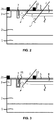
- FIG. 3 is a schematic view for explaining a structure of a photodiode according to the third embodiment.
- a trench structure is formed on the high-resistance semiconductor epitaxial material between the two conductive types of heavily doped regions and may be filled with an insulating material or a plurality of composite insulating material or light reflecting material such as silicon oxide, silicon nitride.
- an insulating material or a plurality of composite insulating material or light reflecting material such as silicon oxide, silicon nitride.
- the first conductive type heavily doped region facilitates spreading of the hole carriers arriving here in an opposite direction (i.e., a direction of the active region), to improve the light response and collection efficiency at the edge of the active region.
- a trench 7 is formed by etching and filling between the N+ type semiconductor region 3 and the P+ type semiconductor region 4. Then, N+ ion implantation is performed to form an N+ type semiconductor region 31 at the bottom and the sidewall of the trench.
- the thickness of the N+ type semiconductor region 31 is about 0.1 to 1 ⁇ m.
- the trench may be filled with an insulating material or a plurality of composite insulating material or light reflecting material such as silicon oxide, silicon nitride.
- the hole carriers arriving here may spread in the opposite direction (i.e., the direction of the active region) under control of physical isolation and an energy band, to improve the light response and collection efficiency at the edge of the active region.
- FIG. 4 is a schematic view for explaining a structure of a photodiode according to the fourth embodiment.
- a trench structure is formed on the high-resistance semiconductor epitaxial material between the two conductive types of heavily doped regions, and may be constituted with a gap structure.
- the bottom and the sidewall of the gap structure may be covered with an insulating material or a plurality of composite insulating material or light reflecting material. Through physical isolation, it is possible to effectively block the hole carriers from spreading to the non-active region, thereby improving the light response and collection efficiency at the edge of the active region.
- a trench 7 is formed by etching and filling between the N+ type semiconductor region 3 and the P+ type semiconductor region 4. Then, an insulating material or a plurality of composite insulating material or light reflecting material 5 such as silicon oxide, silicon nitride is grown at the bottom and the sidewall of the trench.
- the trench is a gap structure 8.
- the thickness of an insulating material or a plurality of composite insulating material or light reflecting material 5 such as silicon oxide, silicon nitride is about 0.1 to 1 ⁇ m.
- the trench as the gap structure can well limit the activity range of hole carriers in the epitaxial layer 2 of the semiconductor substrate, effectively prevent the loss of a part of the hole carrier signals and increase the probability of hole carriers being collected by the active region.
- the light response and collection efficiency of the edge of the active region can be improved, and then the charge collection consistency at different positions of active regions of the pixel can be balanced.
- FIG. 5 is a schematic view for explaining a structure of a photodiode according to the fifth embodiment.
- a trench structure is formed on the high-resistance semiconductor epitaxial material between the two conductive types of heavily doped regions, and may be constituted with a gap structure.
- the bottom and the sidewall of the gap structure may be covered with an insulating material or a plurality of composite insulating material or light reflecting material.
- a heavily doped region of the same doped type as the epitaxial wafer is formed around the trench. Through physical isolation, it is possible to effectively block the hole carriers from spreading to the non-active region.
- the second conductive type heavily doped region increases the hole energy band of the trench region and facilitates spreading of hole carriers arriving here in an opposite direction (i.e., the direction of the active region).
- a trench 7 is formed by etching and filling between the N+ type semiconductor region 3 and the P+ type semiconductor region 4. Then, N+ ion implantation is performed to form an N+ type semiconductor region 32 at the bottom and the sidewall of the trench.
- the thickness of the N+ type semiconductor region 31 is about 0.1 to 1 ⁇ m.
- An insulating material or a plurality of composite insulating material or light reflecting material 32 such as silicon oxide, silicon nitride is grown at the bottom and the sidewall of the trench.
- the trench is a gap structure 8.
- the hole carriers arriving here may spread in the opposite direction (i.e., the direction of the active region) under control of physical isolation and an energy band of the trench as the gap structure, to improve the light response and collection efficiency at the edge of the active region.
- FIG. 6 is a schematic view for explaining a structure of a photodiode according to the sixth embodiment.
- a trench structure is formed on the high-resistance semiconductor epitaxial material between the two conductive types of heavily doped regions, may be covered with an insulating material or a plurality of composite insulating material or light reflecting material, and then filled with monocrystalline semiconductor or polycrystalline semiconductor material. Through physical isolation, it is possible to effectively block the hole carriers from spreading to the non-active region.
- the monocrystalline semiconductor material or the polycrystalline semiconductor material can be connected to a zero potential, a floating state, or a high potential relative to the second conductive electrode (extraction electrode of the heavily doped region for light collection). Introducing of an externally applied electric field facilitates spreading of hole carriers arriving here in an opposite direction (i.e., the direction of the active region), to improve the light response and collection efficiency at the edge of the active region.
- a trench is formed by etching and filling between the N+ type semiconductor region 3 and the P+ type semiconductor region 4. Then an insulating material or a plurality of composite insulating material or light reflecting material 34 such as silicon oxide, silicon nitride is grown at the bottom and the sidewall of the trench.
- the trench may be filled with the N+ type of P+ type monocrystalline or polycrystalline semiconductor material 10.
- the N+ type of P+ type monocrystalline or polycrystalline semiconductor 10 is controlled by an externally applied potential, and may be at zero bias, floating state, or forward bias.
- the hole carriers When the N+ or P+ type monocrystalline or polycrystalline semiconductor material 10 is forward biased, an electric field is generated in the semiconductor in a direction of from the N+ or P+ type monocrystalline or polycrystalline semiconductor 10 to the P+ type semiconductor region 4. Accordingly, when the hole carriers spread or drift to an insulating material or a plurality of composite insulating material or light reflecting material 34 such as silicon oxide, silicon nitride, the hole carriers arriving here may spread in the opposite direction (i.e., the direction of the active region) under control of physical isolation and an energy band of the trench as the gap structure, to improve the light response and collection efficiency at the edge of the active region.
- an insulating material or a plurality of composite insulating material or light reflecting material 34 such as silicon oxide, silicon nitride
- Figure 7 and Figure 8 show the light response and photo-electric collection efficiency corresponding to different incident positions of the light at the edge of active region of the pixel in a photodiode device with a trench (first embodiment) and without trench. It can be seen from the comparison results that a trench isolation structure can improve a probability of the hole carriers being collected at the edge of the active region of the pixel and improve the light response and collection efficiency at the edge of the active region so as to balance the charge collection consistency at different positions of the pixel.
- FIG. 9 is a schematic view for explaining the structure of a photodiode according to the seventh embodiment.
- a photodiode array of the seventh embodiment a thin first conductive type heavily doped region or a second conductive type lightly doped region is formed on a top layer of the active region for collecting light.
- the device surface is easy to introduce defects or impurities such as ions, and these defects will form a capture center, thereby reducing charge amount collected by the electrode.
- Generating of a thinner first conductive type heavily doped region in a top layer of the second conductive type heavily doped region may control the upper limit of the boundary of the internal space charge region not to reach the semiconductor surface when the pixel is at zero bias or reverse bias, and reduce the probability of charges being trapped by structural defects.
- Forming a thinner second conductive type lightly doped region on a top layer of the second conductive type heavily doped region may prevent the hole from spreading or drifting to the device surface, thereby reducing the probability of hole charges being trapped by the structural defects.
- a thinner N+ type semiconductor region 11 is formed by ion implantation, and this region is surrounded by the P+ type semiconductor region 4.
- the N+ type semiconductor region 11, the P+ type semiconductor region 4 and the N- type semiconductor substrate epitaxial layer 2 form an N+/P+/N- structure.
- the upper boundary of the space charge region formed inside the P+ type semiconductor region 4 is limited below the surface of the pixel device, regardless applying the zero bias or the reverse bias to the pixel structure, thereby reducing the probability of holes being trapped by defects of device surface.
- a thinner P- type semiconductor region 11 may be formed on the top layer of the P+ type semiconductor region 4 by a manner of controlling ion implantation energy, and this region is surrounded by the P+ type semiconductor region 4.
- the P- type semiconductor region 11, the P+ type semiconductor region 4 and the N- type semiconductor substrate epitaxial layer 2 form a P-/P+/N-structure regardless the pixel structure is at zero bias or reverse bias.
- the build-in electric field may prevent the holes spreading or drifting to the device surface, thereby reducing the probability of the hole charges being trapped by the structural defects.
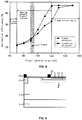
- FIG. 10 is a schematic view for explaining a structure of a photodiode according to the eighth embodiment.
- a further first conductive type heavily doped region is disposed under the second conductive type heavily doped region and the first conductive type heavily doped region, or only a section of first conductive type heavily doped region is disposed under the second conductive type heavily doped region.
- the further first conductive type heavily doped region may be a semiconductor such as monocrystalline silicon, polycrystalline silicon or germanium. This structure can thin the charge-sensitive region and reduce trapping of the hole charges by the traps of the first conductive type lightly-doped region underneath.
- the first conductive type heavily doped regions with the same potential may facilities drifting of the hole charges to the second conductive type heavily doped region, reducing the charge collection time.
- the thinned first conductive type lightly doped regions increase the effective resistance between the two electrodes, further reducing the dark current.
- the further first conductive type heavily doped region in the pixel may be a trench structure extending to the first conductive type heavily doped region of the same layer to completely isolate the inter-pixel structure and further reduce the inter-pixel charge crosstalk effect.
- the further first conductive type heavily doped region may be replaced with an insulating material such as silicon dioxide or silicon nitride.
- a substrate 1 of the semiconductor substrate may be an N+ type region or an N-type region.
- an N+ type semiconductor region 12 is disposed at a position of 5 to 20 ⁇ m below the N+ type semiconductor region 3 and the P+ type semiconductor region 4 of the pixel, and may be a semiconductor material such as monocrystalline silicon, polycrystalline silicon, or germanium.
- the potentials of the N+ type semiconductor region 3 and the N+ type semiconductor region 12 in this pixel are equivalent.
- the electron-hole pairs excited by the photons in the N type semiconductor region 13 respectively drift to the N+ type semiconductor region 3 and the P+ type semiconductor region 4 under the driving of a built-in electric field or an externally applied electric field.
- the N+ type semiconductor region 12, the N- type semiconductor region 13 and the P+ type semiconductor region 4 form an N+/ N-/P+ structure, and the N+ type semiconductor region 12 facilities spreading of the hole carriers to a direction (i.e., the direction of the active region) of the upper P+ type semiconductor region 4, thereby reducing the hole charge collection time.
- the N+ type semiconductor region 12 limits the spreading of the charges excited in the N-type semiconductor region 13 into the N- type semiconductor region 2 and reduces the probability of charges being trapped by the traps in the N- type semiconductor region 2.
- the N+ type semiconductor region 12 reduces the effective charge collection region to the N- type semiconductor region 13 and the electrode N+ type semiconductor region 3 and the P+ type semiconductor region 4 have a lateral structure, the effective resistance between the N+ type semiconductor region 3 and the P+ type semiconductor region 4 is increased, thereby reducing the dark current of the pixel.
- the N+ type semiconductor region 12 may be an overall continuous structure, or may be disposed only under the P+ type semiconductor region 4, and the specific size of it may be adjusted according to requirements.
- a substrate 1 of the semiconductor substrate may be an N+ type region or an N- type region (that is, regions 1 and 2 being high-resistance semiconductor wafers of the same type region).
- an insulating material 12 such as silicon dioxide or silicon nitride is disposed at a position of 5 to 15 ⁇ m below the N+ type semiconductor region 3 and the P+ type semiconductor region 4 of the pixel so that the entire semiconductor may be silicon on insulator (SOI) wafer.
- SOI silicon on insulator
- the insulating material 12 such as silicon dioxide or silicon nitride reduces the effective charge collection region to the N- type semiconductor region 13 and the electrode N + -type semiconductor region 3 and the P + -type semiconductor region 4 have a lateral structure, the effective resistance between the N+ type semiconductor region 3 and the P+ type semiconductor region 4 is increased, so that the dark current of the pixel is further reduced.
- the insulating material 12 such as silicon oxide or silicon nitride may be an integral continuous structure, or may be disposed only under the P+ type semiconductor region 4, and the specific size of it may be adjusted according to requirements.
- FIG. 11 is a schematic view for explaining a structure of a photodiode according to the ninth embodiment.
- a conductive structure with an insulating layer is disposed under the second conductive type heavily doped region and the first conductive type heavily doped region, or only a section of a conductive structure with insulation layer is disposed under the second conductive type heavily doped region.
- the conductive structure with the insulating layer may be made of an insulating material such as silicon dioxide or silicon nitride, a semiconductor material such as heavily doped monocrystalline silicon, polycrystalline silicon, or germanium, and an insulating material such as silicon dioxide or silicon nitride.
- the conductive structure with insulating layer potential can be controlled independently.
- the conductive structure with the insulating layer can thin the charge-sensitive region and reduce trapping of the hole charges by the traps of the first conductive type lightly-doped region underneath.
- the first conductive type heavily doped regions and the conductive structures with the same potential facilities drifting of the hole charges to the second conductive type heavily doped regions, reducing the charge collection time.
- the thinned first conductive type lightly doped regions increase the effective resistance between the two electrodes, thereby reducing the dark current.
- the first conductive type heavily doped region in the pixel may be a trench structure extending to a semiconductor material such as heavily doped monocrystalline silicon, polycrystalline silicon, or germanium in the conductive structure with the insulating layer, completely isolate the inter-pixel structure and reduce the inter-pixel charge crosstalk effect.
- a substrate 1 of the semiconductor substrate may be an N+ type region.
- an N+ type semiconductor region 12 is disposed at a position of 5 to 15 ⁇ m below the N+ type semiconductor region 3 and the P+ type semiconductor region 4 of the pixel, and may be a semiconductor material such as monocrystalline silicon, polycrystalline silicon, or germanium.
- the N+ type semiconductor region 3 is a trench structure extending to the N+ type semiconductor region 12, so that the potential distributions of the N+ type semiconductor region 3 and the N+ type semiconductor region 12 in the pixel are the same.
- the electron-hole pairs excited by the photons in the N- type semiconductor region 13 respectively drift to the N+ type semiconductor region 3 and the P+ type semiconductor region 4 under the driving of a built-in electric field or an externally applied electric field.
- the N+ type semiconductor region 12, the N- type semiconductor region 13 and the P+ type semiconductor region 4 form an N+/N-/P+ structure, and the N+ type semiconductor region 12 facilities spreading of the hole carriers in a direction (i.e., the direction of the active region) of the upper P+ type semiconductor region 4, thereby reducing the hole charge collection time.
- N+ type semiconductor region 3 with the trench structure and the insulating material 12 such as silicon dioxide or silicon nitride completely isolate the pixel from the pixel structure and further suppress the inter-pixel crosstalk effect.
- the N+ type semiconductor region 12 limits the spreading of the charges excited in the N- type semiconductor region 13 to the N- type semiconductor region 2 and reduces the probability of charges being trapped by the traps in the N- type semiconductor region 2.
- the N+ type semiconductor region 12 reduces the effective charge collection region to the N- type semiconductor region 13 and the electrode N+ type semiconductor region 3 and the P+ type semiconductor region 4 have a lateral structure, the effective resistance between the N+ type semiconductor region 3 and the P+ type semiconductor region 4 is increased, thereby reducing the dark current of the pixel.
- the N+ type semiconductor region 12 may be an overall continuous structure, or may be disposed only under the P+ type semiconductor region 4, and the specific size of it may be adjusted according to requirements
- a substrate 1 of a semiconductor substrate may be an N+ type region or an N- type region (that is, regions 1 and 2 are a high-resistance semiconductor wafer of the same type region).
- an insulating material 12 such as silicon dioxide or silicon nitride is disposed at a position of 5 to15 ⁇ m below the N+ type semiconductor region 3 and the P+ type semiconductor region 4 of the pixel so that the entire semiconductor may be silicon on insulator (SOI) wafer.
- SOI silicon on insulator
- the N+ type semiconductor region 3 is a trench structure extending to the insulating material 12 such as silicon dioxide or silicon nitride.
- the N+ type semiconductor region 3 having the trench structure and an insulating material 12 such as silicon dioxide or silicon nitride isolate the pixel from the pixel structure completely, thereby suppressing the inter-pixel charge crosstalk effect.
- the insulating material 12 such as silicon dioxide or silicon nitride limits the spreading of the charges excited in the N- type semiconductor region 13 to the N- type semiconductor region 2 and reduces the probability of charges being trapped by the traps in the N- type semiconductor region 2.
- the insulating material 12 such as silicon dioxide or silicon nitride reduces the effective charge collection region to the N- type semiconductor region 13 and the electrode N+ type semiconductor region 3 and the P+ type semiconductor region 4 have a lateral structure, the effective resistance between the N+ type semiconductor region 3 and the P+ type semiconductor region 4 is increased, so that the dark current of the pixel is further reduced.
- the insulating material 12 such as silicon oxide or silicon nitride may be an integral continuous structure, or may be disposed only under the P+ type semiconductor region 4, and the specific size of it may be adjusted according to requirements.
- a substrate 1 of a semiconductor substrate may be an N+ type region or may be an N-type region.
- a conductive structure with an insulating layer which is respectively an insulating layer 14 such as silicon dioxide or silicon nitride, a heavily doped semiconductor material 15 such as monocrystalline silicon, polycrystalline silicon, or germanium, and an insulating layer 16 such as silicon dioxide or a silicon nitride, is disposed at a position of 5 to 15 ⁇ m below the N+ type semiconductor region 3 and the P+ type semiconductor region 4 of the pixel.
- This overall is a double-layer silicon on insulator (DSOI) wafer structure.
- DSOI double-layer silicon on insulator
- the heavily doped semiconductor material 15 such as monocrystalline silicon, polycrystalline silicon, or germanium can be independently controlled in potential to modulate an electric field distribution inside the N- type semiconductor region 13.
- the electron-hole pairs excited by the photons in the N- type semiconductor region 13 respectively spread to the N+ type semiconductor region 3 and the P+ type semiconductor region 4 under the driving of a built-in electric field or an externally applied electric field drift.
- the heavily doped semiconductor material 15 such as monocrystalline silicon, polycrystalline silicon, or germanium facilities the hole carriers spreading in the direction of the upper P+ type semiconductor region 4 (i.e., in the direction of the active region), thereby reducing the hole charge collection time.
- the conductive structure with an insulating layer limits the spreading of the charges excited in in the N- type semiconductor region 13 to the N- type semiconductor region 2 and reduces the probability of charges being trapped by the traps in the N- type semiconductor region 2.
- the conductive structure with the insulating layer reduces the effective charge collection region to the N- type semiconductor region 13, and the electrode N+ type semiconductor region 3 and the P+ type semiconductor region 4 have a lateral structure, the effective resistance between the N+ type semiconductor region 3 and the P+ type semiconductor region 4 is increased, thereby reducing the dark current of the pixel.
- the conductive structure with insulating layers 14, 15 and 16 in this embodiment may be of an integral continuous structure, or may be disposed only under the P+ type semiconductor region 4, and the specific size of it may be adjusted according to requirements.
- a substrate 1 of a semiconductor substrate may be an N+ type region or an N- type region.
- a conductive structure with an insulating layer which is respectively an insulating layer 14 such as silicon dioxide or a silicon nitride, a heavily doped semiconductor material 15 such as monocrystalline silicon, polycrystalline silicon, or germanium, an insulating layer 16 such as silicon dioxide or a silicon nitride, is disposed at a position of 5 to 15 ⁇ m below the N+ type semiconductor region 3 and the P+ type semiconductor region 4 of the pixel.
- This overall is a double-layer silicon on insulator (DSOI) wafer structure.
- DSOI double-layer silicon on insulator
- the N+ type semiconductor region 3 is a trench structure extending to the heavily-doped semiconductor material 15 such as monocrystalline silicon, polycrystalline silicon or germanium, the N+ type semiconductor region 3 as the trench structure and the conductive structure with the insulating layer isolate the pixel from the pixel structure completely, thereby suppressing the inter-pixel charge crosstalk effect.
- the heavily doped semiconductor material 15 such as monocrystalline silicon, polycrystalline silicon, or germanium has the same potential as the N+ type semiconductor region 3, so that the electric field distribution in the N- type semiconductor region 13 can be modulated by controlling the potential of the N+ type semiconductor region 3.
- the electron-hole pairs excited by the photons in the N- type semiconductor region 13 respectively drift to the N+ type semiconductor region 3 and the P+ type semiconductor region 4 under the driving of a built-in electric field or an externally applied electric field.
- the heavily doped semiconductor material 15 such as monocrystalline silicon, polycrystalline silicon, or germanium facilities the hole carriers spreading in the direction of the upper P+ type semiconductor region 4 (i.e., in the direction of the active region), thereby reducing the hole charge collection time.
- the conductive structure with the insulating layer limits the spreading of the charges excited in the N- type semiconductor region 13 to the N- type semiconductor region 2 and reduces the probability of charge being trapped by the traps in the N-type semiconductor region 2.
- the conductive structure with the insulating layer reduces the effective charge collection region to the N- type semiconductor region 13, and the electrode N+ type semiconductor region 3 and the P+ type semiconductor region 4 have a lateral structure, the effective resistance between the N+ type semiconductor region 3 and the P+ type semiconductor region 4 is increased, thereby reducing the dark current of the pixel.
- the conductive structure with insulating layers 14, 15 and 16 in this embodiment may be of an integral continuous structure, or may be disposed only under the P+ type semiconductor region 4, and the specific size of it may be adjusted according to requirements.
- the photodiode array of the above embodiments of the present disclosure is mainly applied to a 200 to 600 nm wavelength X-ray detector (emits light with a wavelength of about 550 nm through a scintillator such as Csl) and is mainly absorbed within 5 micrometers of depth of the surface of the silicon epitaxial wafer. Therefore, the trench isolation structure, the first conductive heavily doped layer, the depth of the insulating material layer, and the conductive structure with the insulating layer can be controlled to be between 5 and 20 ⁇ m. In this case, as described above, the action effect of the trench structure can be ensured.
- the photodiode array according to the embodiments of the present disclosure operates in the wavelength range of 200 to 600 nm, the light absorption in the active area of the pixel has better consistency, reduces the dark current of the pixel, and accelerates the pixel charge collection rate.
Landscapes
- Engineering & Computer Science (AREA)
- Physics & Mathematics (AREA)
- Power Engineering (AREA)
- Electromagnetism (AREA)
- Condensed Matter Physics & Semiconductors (AREA)
- General Physics & Mathematics (AREA)
- Computer Hardware Design (AREA)
- Microelectronics & Electronic Packaging (AREA)
- Manufacturing & Machinery (AREA)
- Health & Medical Sciences (AREA)
- Toxicology (AREA)
- Light Receiving Elements (AREA)
Applications Claiming Priority (2)
| Application Number | Priority Date | Filing Date | Title |
|---|---|---|---|
| CN201511010038.8A CN105448945B (zh) | 2015-12-29 | 2015-12-29 | 同面电极光电二极管阵列及其制作方法 |
| PCT/CN2016/097517 WO2017113846A1 (fr) | 2015-12-29 | 2016-08-31 | Réseau de photodiodes d'électrode coplanaire et son procédé de fabrication |
Publications (3)
| Publication Number | Publication Date |
|---|---|
| EP3399552A1 true EP3399552A1 (fr) | 2018-11-07 |
| EP3399552A4 EP3399552A4 (fr) | 2019-08-07 |
| EP3399552B1 EP3399552B1 (fr) | 2021-06-30 |
Family
ID=55558955
Family Applications (1)
| Application Number | Title | Priority Date | Filing Date |
|---|---|---|---|
| EP16880639.6A Active EP3399552B1 (fr) | 2015-12-29 | 2016-08-31 | Réseau de photodiodes d'électrode coplanaire et son procédé de fabrication |
Country Status (5)
| Country | Link |
|---|---|
| US (1) | US10411051B2 (fr) |
| EP (1) | EP3399552B1 (fr) |
| JP (1) | JP6577601B2 (fr) |
| CN (1) | CN105448945B (fr) |
| WO (1) | WO2017113846A1 (fr) |
Families Citing this family (9)
| Publication number | Priority date | Publication date | Assignee | Title |
|---|---|---|---|---|
| CN105448945B (zh) | 2015-12-29 | 2019-07-05 | 同方威视技术股份有限公司 | 同面电极光电二极管阵列及其制作方法 |
| CN106784071B (zh) | 2016-12-07 | 2018-09-28 | 同方威视技术股份有限公司 | 光电二极管器件、光电二极管探测器及其制造方法 |
| CN107195723B (zh) * | 2017-06-30 | 2020-05-15 | 上海集成电路研发中心有限公司 | 一种雪崩光敏器件及其制备方法 |
| CN108414786B (zh) * | 2018-01-26 | 2020-03-27 | 中国科学院大气物理研究所 | 一种双线光电二极管阵列器件及粒子速度测量方法 |
| CN108562762B (zh) * | 2018-01-26 | 2020-03-27 | 中国科学院大气物理研究所 | 一种基于双线阵的海洋飞沫测量装置及方法 |
| FI130492B (en) | 2018-01-26 | 2023-10-05 | Inst Of Atmospheric Physics Chinese Academy Of Sciences | Two-row diode array device and measurement method and particle velocity measurement device |
| CN110504278A (zh) * | 2019-08-28 | 2019-11-26 | 无锡中微晶园电子有限公司 | 一种防串流光敏二极管芯片及其制造方法 |
| CN113299786B (zh) * | 2021-05-21 | 2023-05-23 | 武汉新芯集成电路制造有限公司 | 半导体器件及其制造方法 |
| CN116154022B (zh) * | 2023-03-14 | 2024-03-22 | 江南大学 | 一种双层SiO2隔离的光电二极管结构、阵列及制造方法 |
Family Cites Families (18)
| Publication number | Priority date | Publication date | Assignee | Title |
|---|---|---|---|---|
| JPS5310987A (en) * | 1976-07-16 | 1978-01-31 | Sony Corp | Photoelectric transducing semiconductor device |
| JPH0760887B2 (ja) * | 1984-10-01 | 1995-06-28 | オリンパス光学工業株式会社 | 半導体光電変換装置 |
| US5549762A (en) * | 1995-01-13 | 1996-08-27 | International Rectifier Corporation | Photovoltaic generator with dielectric isolation and bonded, insulated wafer layers |
| JP2000312021A (ja) | 1999-04-26 | 2000-11-07 | Sony Corp | 半導体装置とその製造方法 |
| JP2002353431A (ja) * | 2001-05-22 | 2002-12-06 | Canon Inc | 光電変換装置及びその製造方法 |
| JP4342142B2 (ja) * | 2002-03-22 | 2009-10-14 | 富士通マイクロエレクトロニクス株式会社 | 半導体受光素子 |
| WO2005001939A1 (fr) * | 2003-06-30 | 2005-01-06 | Rohm Co., Ltd. | Capteur d'image et procede de formation d'une structure isolante pour photodiode |
| JP2005045125A (ja) * | 2003-07-24 | 2005-02-17 | Hamamatsu Photonics Kk | 光検出素子の製造方法 |
| US7492027B2 (en) * | 2004-02-20 | 2009-02-17 | Micron Technology, Inc. | Reduced crosstalk sensor and method of formation |
| US8188563B2 (en) * | 2006-07-21 | 2012-05-29 | The Regents Of The University Of California | Shallow-trench-isolation (STI)-bounded single-photon CMOS photodetector |
| JP2008066446A (ja) * | 2006-09-06 | 2008-03-21 | Sony Corp | 半導体積層構造および半導体素子 |
| JP2010278045A (ja) * | 2009-05-26 | 2010-12-09 | Panasonic Corp | 光半導体装置 |
| JP5726005B2 (ja) * | 2010-08-02 | 2015-05-27 | アイメックImec | Cmos撮像装置アレイの製造方法 |
| US9160949B2 (en) * | 2013-04-01 | 2015-10-13 | Omnivision Technologies, Inc. | Enhanced photon detection device with biased deep trench isolation |
| CN103594468B (zh) * | 2013-11-29 | 2016-08-31 | 电子科技大学 | 一种快速光电探测器 |
| CN105185796B (zh) * | 2015-09-30 | 2018-06-29 | 南京邮电大学 | 一种高探测效率的单光子雪崩二极管探测器阵列单元 |
| CN205319156U (zh) * | 2015-12-29 | 2016-06-15 | 同方威视技术股份有限公司 | 同面电极光电二极管阵列 |
| CN105448945B (zh) * | 2015-12-29 | 2019-07-05 | 同方威视技术股份有限公司 | 同面电极光电二极管阵列及其制作方法 |
-
2015
- 2015-12-29 CN CN201511010038.8A patent/CN105448945B/zh active Active
-
2016
- 2016-08-31 JP JP2017562301A patent/JP6577601B2/ja not_active Expired - Fee Related
- 2016-08-31 EP EP16880639.6A patent/EP3399552B1/fr active Active
- 2016-08-31 US US15/580,848 patent/US10411051B2/en active Active
- 2016-08-31 WO PCT/CN2016/097517 patent/WO2017113846A1/fr active Application Filing
Also Published As
| Publication number | Publication date |
|---|---|
| US20180342542A1 (en) | 2018-11-29 |
| EP3399552A4 (fr) | 2019-08-07 |
| JP6577601B2 (ja) | 2019-09-18 |
| EP3399552B1 (fr) | 2021-06-30 |
| CN105448945A (zh) | 2016-03-30 |
| JP2018518838A (ja) | 2018-07-12 |
| WO2017113846A1 (fr) | 2017-07-06 |
| US10411051B2 (en) | 2019-09-10 |
| CN105448945B (zh) | 2019-07-05 |
Similar Documents
| Publication | Publication Date | Title |
|---|---|---|
| EP3399552B1 (fr) | Réseau de photodiodes d'électrode coplanaire et son procédé de fabrication | |
| CN109690792B (zh) | Spad光电二极管 | |
| US10347670B2 (en) | Photodetection element | |
| US11189741B2 (en) | Photodiode device, photodiode detector and methods of fabricating the same | |
| EP3544064B1 (fr) | Photodétecteur et détection et télémétrie de la lumière | |
| KR102682692B1 (ko) | 애벌란치 포토다이오드 어레이 | |
| US8946617B2 (en) | Photodiode having a p-n junction with varying expansion of the space charge zone due to application of a variable voltage | |
| EP3477710B1 (fr) | Photodiode à avalanche et procédé de fabrication de photodiode à avalanche | |
| RU2641620C1 (ru) | Лавинный фотодетектор | |
| WO2007077286A1 (fr) | Detecteur de rayonnements de semi-conducteurs detectant la lumiere visible | |
| CN107895743B (zh) | 单光子雪崩光电二极管探测器的装置和方法 | |
| US8994138B2 (en) | Hardened photodiode image sensor | |
| CN114899267B (zh) | 光电转换器件、感测装置、电子设备及制造方法 | |
| US11011656B2 (en) | Photodiode device and photodiode detector | |
| JP2013145180A (ja) | 放射線検出器,放射線検出装置及びそれらの動作方法 | |
| EP1833095A1 (fr) | Photodiode avec un courant d'obscurité réduit | |
| CN205319156U (zh) | 同面电极光电二极管阵列 | |
| US5583352A (en) | Low-noise, reach-through, avalanche photodiodes | |
| KR20230032568A (ko) | Spad 구조 | |
| CN206412371U (zh) | 光电二极管器件及光电二极管探测器 | |
| JP7421233B2 (ja) | アバランシェ光検出器(変形形態)およびこれを製造するための方法(変形形態) | |
| KR20210137455A (ko) | 눈사태형 광검출기(변형물) 및 그 제조 방법(변형) | |
| KR20230021300A (ko) | 후면조사 이미지센서에서의 spad 픽셀 구조 | |
| CN117374087A (zh) | 光电探测器及单光子探测系统 | |
| US20180254300A1 (en) | Photodiode matrix with isolated cathodes |
Legal Events
| Date | Code | Title | Description |
|---|---|---|---|
| STAA | Information on the status of an ep patent application or granted ep patent |
Free format text: STATUS: THE INTERNATIONAL PUBLICATION HAS BEEN MADE |
|
| PUAI | Public reference made under article 153(3) epc to a published international application that has entered the european phase |
Free format text: ORIGINAL CODE: 0009012 |
|
| STAA | Information on the status of an ep patent application or granted ep patent |
Free format text: STATUS: REQUEST FOR EXAMINATION WAS MADE |
|
| 17P | Request for examination filed |
Effective date: 20171207 |
|
| AK | Designated contracting states |
Kind code of ref document: A1 Designated state(s): AL AT BE BG CH CY CZ DE DK EE ES FI FR GB GR HR HU IE IS IT LI LT LU LV MC MK MT NL NO PL PT RO RS SE SI SK SM TR |
|
| AX | Request for extension of the european patent |
Extension state: BA ME |
|
| DAV | Request for validation of the european patent (deleted) | ||
| DAX | Request for extension of the european patent (deleted) | ||
| A4 | Supplementary search report drawn up and despatched |
Effective date: 20190705 |
|
| RIC1 | Information provided on ipc code assigned before grant |
Ipc: H01L 27/146 20060101AFI20190701BHEP |
|
| STAA | Information on the status of an ep patent application or granted ep patent |
Free format text: STATUS: EXAMINATION IS IN PROGRESS |
|
| 17Q | First examination report despatched |
Effective date: 20200703 |
|
| STAA | Information on the status of an ep patent application or granted ep patent |
Free format text: STATUS: EXAMINATION IS IN PROGRESS |
|
| GRAP | Despatch of communication of intention to grant a patent |
Free format text: ORIGINAL CODE: EPIDOSNIGR1 |
|
| STAA | Information on the status of an ep patent application or granted ep patent |
Free format text: STATUS: GRANT OF PATENT IS INTENDED |
|
| INTG | Intention to grant announced |
Effective date: 20210304 |
|
| GRAS | Grant fee paid |
Free format text: ORIGINAL CODE: EPIDOSNIGR3 |
|
| GRAA | (expected) grant |
Free format text: ORIGINAL CODE: 0009210 |
|
| STAA | Information on the status of an ep patent application or granted ep patent |
Free format text: STATUS: THE PATENT HAS BEEN GRANTED |
|
| AK | Designated contracting states |
Kind code of ref document: B1 Designated state(s): AL AT BE BG CH CY CZ DE DK EE ES FI FR GB GR HR HU IE IS IT LI LT LU LV MC MK MT NL NO PL PT RO RS SE SI SK SM TR |
|
| REG | Reference to a national code |
Ref country code: CH Ref legal event code: EP |
|
| REG | Reference to a national code |
Ref country code: DE Ref legal event code: R096 Ref document number: 602016060143 Country of ref document: DE Ref country code: AT Ref legal event code: REF Ref document number: 1407149 Country of ref document: AT Kind code of ref document: T Effective date: 20210715 |
|
| REG | Reference to a national code |
Ref country code: IE Ref legal event code: FG4D |
|
| REG | Reference to a national code |
Ref country code: LT Ref legal event code: MG9D |
|
| PG25 | Lapsed in a contracting state [announced via postgrant information from national office to epo] |
Ref country code: BG Free format text: LAPSE BECAUSE OF FAILURE TO SUBMIT A TRANSLATION OF THE DESCRIPTION OR TO PAY THE FEE WITHIN THE PRESCRIBED TIME-LIMIT Effective date: 20210930 Ref country code: HR Free format text: LAPSE BECAUSE OF FAILURE TO SUBMIT A TRANSLATION OF THE DESCRIPTION OR TO PAY THE FEE WITHIN THE PRESCRIBED TIME-LIMIT Effective date: 20210630 Ref country code: FI Free format text: LAPSE BECAUSE OF FAILURE TO SUBMIT A TRANSLATION OF THE DESCRIPTION OR TO PAY THE FEE WITHIN THE PRESCRIBED TIME-LIMIT Effective date: 20210630 |
|
| REG | Reference to a national code |
Ref country code: NL Ref legal event code: MP Effective date: 20210630 |
|
| REG | Reference to a national code |
Ref country code: AT Ref legal event code: MK05 Ref document number: 1407149 Country of ref document: AT Kind code of ref document: T Effective date: 20210630 |
|
| PG25 | Lapsed in a contracting state [announced via postgrant information from national office to epo] |
Ref country code: GR Free format text: LAPSE BECAUSE OF FAILURE TO SUBMIT A TRANSLATION OF THE DESCRIPTION OR TO PAY THE FEE WITHIN THE PRESCRIBED TIME-LIMIT Effective date: 20211001 Ref country code: LV Free format text: LAPSE BECAUSE OF FAILURE TO SUBMIT A TRANSLATION OF THE DESCRIPTION OR TO PAY THE FEE WITHIN THE PRESCRIBED TIME-LIMIT Effective date: 20210630 Ref country code: NO Free format text: LAPSE BECAUSE OF FAILURE TO SUBMIT A TRANSLATION OF THE DESCRIPTION OR TO PAY THE FEE WITHIN THE PRESCRIBED TIME-LIMIT Effective date: 20210930 Ref country code: RS Free format text: LAPSE BECAUSE OF FAILURE TO SUBMIT A TRANSLATION OF THE DESCRIPTION OR TO PAY THE FEE WITHIN THE PRESCRIBED TIME-LIMIT Effective date: 20210630 Ref country code: SE Free format text: LAPSE BECAUSE OF FAILURE TO SUBMIT A TRANSLATION OF THE DESCRIPTION OR TO PAY THE FEE WITHIN THE PRESCRIBED TIME-LIMIT Effective date: 20210630 |
|
| PG25 | Lapsed in a contracting state [announced via postgrant information from national office to epo] |
Ref country code: ES Free format text: LAPSE BECAUSE OF FAILURE TO SUBMIT A TRANSLATION OF THE DESCRIPTION OR TO PAY THE FEE WITHIN THE PRESCRIBED TIME-LIMIT Effective date: 20210630 Ref country code: NL Free format text: LAPSE BECAUSE OF FAILURE TO SUBMIT A TRANSLATION OF THE DESCRIPTION OR TO PAY THE FEE WITHIN THE PRESCRIBED TIME-LIMIT Effective date: 20210630 Ref country code: PT Free format text: LAPSE BECAUSE OF FAILURE TO SUBMIT A TRANSLATION OF THE DESCRIPTION OR TO PAY THE FEE WITHIN THE PRESCRIBED TIME-LIMIT Effective date: 20211102 Ref country code: RO Free format text: LAPSE BECAUSE OF FAILURE TO SUBMIT A TRANSLATION OF THE DESCRIPTION OR TO PAY THE FEE WITHIN THE PRESCRIBED TIME-LIMIT Effective date: 20210630 Ref country code: AT Free format text: LAPSE BECAUSE OF FAILURE TO SUBMIT A TRANSLATION OF THE DESCRIPTION OR TO PAY THE FEE WITHIN THE PRESCRIBED TIME-LIMIT Effective date: 20210630 Ref country code: CZ Free format text: LAPSE BECAUSE OF FAILURE TO SUBMIT A TRANSLATION OF THE DESCRIPTION OR TO PAY THE FEE WITHIN THE PRESCRIBED TIME-LIMIT Effective date: 20210630 Ref country code: EE Free format text: LAPSE BECAUSE OF FAILURE TO SUBMIT A TRANSLATION OF THE DESCRIPTION OR TO PAY THE FEE WITHIN THE PRESCRIBED TIME-LIMIT Effective date: 20210630 Ref country code: SM Free format text: LAPSE BECAUSE OF FAILURE TO SUBMIT A TRANSLATION OF THE DESCRIPTION OR TO PAY THE FEE WITHIN THE PRESCRIBED TIME-LIMIT Effective date: 20210630 Ref country code: SK Free format text: LAPSE BECAUSE OF FAILURE TO SUBMIT A TRANSLATION OF THE DESCRIPTION OR TO PAY THE FEE WITHIN THE PRESCRIBED TIME-LIMIT Effective date: 20210630 |
|
| PG25 | Lapsed in a contracting state [announced via postgrant information from national office to epo] |
Ref country code: PL Free format text: LAPSE BECAUSE OF FAILURE TO SUBMIT A TRANSLATION OF THE DESCRIPTION OR TO PAY THE FEE WITHIN THE PRESCRIBED TIME-LIMIT Effective date: 20210630 |
|
| REG | Reference to a national code |
Ref country code: DE Ref legal event code: R119 Ref document number: 602016060143 Country of ref document: DE |
|
| REG | Reference to a national code |
Ref country code: CH Ref legal event code: PL |
|
| PG25 | Lapsed in a contracting state [announced via postgrant information from national office to epo] |
Ref country code: MC Free format text: LAPSE BECAUSE OF FAILURE TO SUBMIT A TRANSLATION OF THE DESCRIPTION OR TO PAY THE FEE WITHIN THE PRESCRIBED TIME-LIMIT Effective date: 20210630 |
|
| REG | Reference to a national code |
Ref country code: BE Ref legal event code: MM Effective date: 20210831 |
|
| PG25 | Lapsed in a contracting state [announced via postgrant information from national office to epo] |
Ref country code: LI Free format text: LAPSE BECAUSE OF NON-PAYMENT OF DUE FEES Effective date: 20210831 Ref country code: DK Free format text: LAPSE BECAUSE OF FAILURE TO SUBMIT A TRANSLATION OF THE DESCRIPTION OR TO PAY THE FEE WITHIN THE PRESCRIBED TIME-LIMIT Effective date: 20210630 Ref country code: CH Free format text: LAPSE BECAUSE OF NON-PAYMENT OF DUE FEES Effective date: 20210831 |
|
| PLBE | No opposition filed within time limit |
Free format text: ORIGINAL CODE: 0009261 |
|
| STAA | Information on the status of an ep patent application or granted ep patent |
Free format text: STATUS: NO OPPOSITION FILED WITHIN TIME LIMIT |
|
| GBPC | Gb: european patent ceased through non-payment of renewal fee |
Effective date: 20210930 |
|
| PG25 | Lapsed in a contracting state [announced via postgrant information from national office to epo] |
Ref country code: LU Free format text: LAPSE BECAUSE OF NON-PAYMENT OF DUE FEES Effective date: 20210831 Ref country code: AL Free format text: LAPSE BECAUSE OF FAILURE TO SUBMIT A TRANSLATION OF THE DESCRIPTION OR TO PAY THE FEE WITHIN THE PRESCRIBED TIME-LIMIT Effective date: 20210630 |
|
| 26N | No opposition filed |
Effective date: 20220331 |
|
| PG25 | Lapsed in a contracting state [announced via postgrant information from national office to epo] |
Ref country code: IT Free format text: LAPSE BECAUSE OF FAILURE TO SUBMIT A TRANSLATION OF THE DESCRIPTION OR TO PAY THE FEE WITHIN THE PRESCRIBED TIME-LIMIT Effective date: 20210630 Ref country code: IE Free format text: LAPSE BECAUSE OF NON-PAYMENT OF DUE FEES Effective date: 20210831 Ref country code: GB Free format text: LAPSE BECAUSE OF NON-PAYMENT OF DUE FEES Effective date: 20210930 Ref country code: FR Free format text: LAPSE BECAUSE OF NON-PAYMENT OF DUE FEES Effective date: 20210831 Ref country code: DE Free format text: LAPSE BECAUSE OF NON-PAYMENT OF DUE FEES Effective date: 20220301 Ref country code: BE Free format text: LAPSE BECAUSE OF NON-PAYMENT OF DUE FEES Effective date: 20210831 |
|
| PG25 | Lapsed in a contracting state [announced via postgrant information from national office to epo] |
Ref country code: LT Free format text: LAPSE BECAUSE OF FAILURE TO SUBMIT A TRANSLATION OF THE DESCRIPTION OR TO PAY THE FEE WITHIN THE PRESCRIBED TIME-LIMIT Effective date: 20210630 |
|
| PG25 | Lapsed in a contracting state [announced via postgrant information from national office to epo] |
Ref country code: CY Free format text: LAPSE BECAUSE OF FAILURE TO SUBMIT A TRANSLATION OF THE DESCRIPTION OR TO PAY THE FEE WITHIN THE PRESCRIBED TIME-LIMIT Effective date: 20210630 |
|
| PG25 | Lapsed in a contracting state [announced via postgrant information from national office to epo] |
Ref country code: HU Free format text: LAPSE BECAUSE OF FAILURE TO SUBMIT A TRANSLATION OF THE DESCRIPTION OR TO PAY THE FEE WITHIN THE PRESCRIBED TIME-LIMIT; INVALID AB INITIO Effective date: 20160831 |
|
| PG25 | Lapsed in a contracting state [announced via postgrant information from national office to epo] |
Ref country code: MK Free format text: LAPSE BECAUSE OF FAILURE TO SUBMIT A TRANSLATION OF THE DESCRIPTION OR TO PAY THE FEE WITHIN THE PRESCRIBED TIME-LIMIT Effective date: 20210630 |