EP3399167B1 - Reduktionsmitteltank mit integriertem fluidkanal zum führen eines heizfluides - Google Patents
Reduktionsmitteltank mit integriertem fluidkanal zum führen eines heizfluides Download PDFInfo
- Publication number
- EP3399167B1 EP3399167B1 EP18179743.2A EP18179743A EP3399167B1 EP 3399167 B1 EP3399167 B1 EP 3399167B1 EP 18179743 A EP18179743 A EP 18179743A EP 3399167 B1 EP3399167 B1 EP 3399167B1
- Authority
- EP
- European Patent Office
- Prior art keywords
- tank
- reducing agent
- segment
- agent tank
- housing
- Prior art date
- Legal status (The legal status is an assumption and is not a legal conclusion. Google has not performed a legal analysis and makes no representation as to the accuracy of the status listed.)
- Active
Links
Images


Classifications
-
- F—MECHANICAL ENGINEERING; LIGHTING; HEATING; WEAPONS; BLASTING
- F01—MACHINES OR ENGINES IN GENERAL; ENGINE PLANTS IN GENERAL; STEAM ENGINES
- F01N—GAS-FLOW SILENCERS OR EXHAUST APPARATUS FOR MACHINES OR ENGINES IN GENERAL; GAS-FLOW SILENCERS OR EXHAUST APPARATUS FOR INTERNAL COMBUSTION ENGINES
- F01N3/00—Exhaust or silencing apparatus having means for purifying, rendering innocuous, or otherwise treating exhaust
- F01N3/08—Exhaust or silencing apparatus having means for purifying, rendering innocuous, or otherwise treating exhaust for rendering innocuous
- F01N3/10—Exhaust or silencing apparatus having means for purifying, rendering innocuous, or otherwise treating exhaust for rendering innocuous by thermal or catalytic conversion of noxious components of exhaust
- F01N3/24—Exhaust or silencing apparatus having means for purifying, rendering innocuous, or otherwise treating exhaust for rendering innocuous by thermal or catalytic conversion of noxious components of exhaust characterised by constructional aspects of converting apparatus
- F01N3/28—Construction of catalytic reactors
-
- F—MECHANICAL ENGINEERING; LIGHTING; HEATING; WEAPONS; BLASTING
- F01—MACHINES OR ENGINES IN GENERAL; ENGINE PLANTS IN GENERAL; STEAM ENGINES
- F01N—GAS-FLOW SILENCERS OR EXHAUST APPARATUS FOR MACHINES OR ENGINES IN GENERAL; GAS-FLOW SILENCERS OR EXHAUST APPARATUS FOR INTERNAL COMBUSTION ENGINES
- F01N3/00—Exhaust or silencing apparatus having means for purifying, rendering innocuous, or otherwise treating exhaust
- F01N3/08—Exhaust or silencing apparatus having means for purifying, rendering innocuous, or otherwise treating exhaust for rendering innocuous
- F01N3/10—Exhaust or silencing apparatus having means for purifying, rendering innocuous, or otherwise treating exhaust for rendering innocuous by thermal or catalytic conversion of noxious components of exhaust
- F01N3/18—Exhaust or silencing apparatus having means for purifying, rendering innocuous, or otherwise treating exhaust for rendering innocuous by thermal or catalytic conversion of noxious components of exhaust characterised by methods of operation; Control
- F01N3/20—Exhaust or silencing apparatus having means for purifying, rendering innocuous, or otherwise treating exhaust for rendering innocuous by thermal or catalytic conversion of noxious components of exhaust characterised by methods of operation; Control specially adapted for catalytic conversion ; Methods of operation or control of catalytic converters
- F01N3/206—Adding periodically or continuously substances to exhaust gases for promoting purification, e.g. catalytic material in liquid form, NOx reducing agents
-
- F—MECHANICAL ENGINEERING; LIGHTING; HEATING; WEAPONS; BLASTING
- F01—MACHINES OR ENGINES IN GENERAL; ENGINE PLANTS IN GENERAL; STEAM ENGINES
- F01N—GAS-FLOW SILENCERS OR EXHAUST APPARATUS FOR MACHINES OR ENGINES IN GENERAL; GAS-FLOW SILENCERS OR EXHAUST APPARATUS FOR INTERNAL COMBUSTION ENGINES
- F01N3/00—Exhaust or silencing apparatus having means for purifying, rendering innocuous, or otherwise treating exhaust
- F01N3/08—Exhaust or silencing apparatus having means for purifying, rendering innocuous, or otherwise treating exhaust for rendering innocuous
- F01N3/10—Exhaust or silencing apparatus having means for purifying, rendering innocuous, or otherwise treating exhaust for rendering innocuous by thermal or catalytic conversion of noxious components of exhaust
- F01N3/18—Exhaust or silencing apparatus having means for purifying, rendering innocuous, or otherwise treating exhaust for rendering innocuous by thermal or catalytic conversion of noxious components of exhaust characterised by methods of operation; Control
- F01N3/20—Exhaust or silencing apparatus having means for purifying, rendering innocuous, or otherwise treating exhaust for rendering innocuous by thermal or catalytic conversion of noxious components of exhaust characterised by methods of operation; Control specially adapted for catalytic conversion ; Methods of operation or control of catalytic converters
- F01N3/2066—Selective catalytic reduction [SCR]
-
- F—MECHANICAL ENGINEERING; LIGHTING; HEATING; WEAPONS; BLASTING
- F01—MACHINES OR ENGINES IN GENERAL; ENGINE PLANTS IN GENERAL; STEAM ENGINES
- F01N—GAS-FLOW SILENCERS OR EXHAUST APPARATUS FOR MACHINES OR ENGINES IN GENERAL; GAS-FLOW SILENCERS OR EXHAUST APPARATUS FOR INTERNAL COMBUSTION ENGINES
- F01N2610/00—Adding substances to exhaust gases
- F01N2610/02—Adding substances to exhaust gases the substance being ammonia or urea
-
- F—MECHANICAL ENGINEERING; LIGHTING; HEATING; WEAPONS; BLASTING
- F01—MACHINES OR ENGINES IN GENERAL; ENGINE PLANTS IN GENERAL; STEAM ENGINES
- F01N—GAS-FLOW SILENCERS OR EXHAUST APPARATUS FOR MACHINES OR ENGINES IN GENERAL; GAS-FLOW SILENCERS OR EXHAUST APPARATUS FOR INTERNAL COMBUSTION ENGINES
- F01N2610/00—Adding substances to exhaust gases
- F01N2610/10—Adding substances to exhaust gases the substance being heated, e.g. by heating tank or supply line of the added substance
-
- F—MECHANICAL ENGINEERING; LIGHTING; HEATING; WEAPONS; BLASTING
- F01—MACHINES OR ENGINES IN GENERAL; ENGINE PLANTS IN GENERAL; STEAM ENGINES
- F01N—GAS-FLOW SILENCERS OR EXHAUST APPARATUS FOR MACHINES OR ENGINES IN GENERAL; GAS-FLOW SILENCERS OR EXHAUST APPARATUS FOR INTERNAL COMBUSTION ENGINES
- F01N2610/00—Adding substances to exhaust gases
- F01N2610/14—Arrangements for the supply of substances, e.g. conduits
- F01N2610/1406—Storage means for substances, e.g. tanks or reservoirs
-
- F—MECHANICAL ENGINEERING; LIGHTING; HEATING; WEAPONS; BLASTING
- F01—MACHINES OR ENGINES IN GENERAL; ENGINE PLANTS IN GENERAL; STEAM ENGINES
- F01N—GAS-FLOW SILENCERS OR EXHAUST APPARATUS FOR MACHINES OR ENGINES IN GENERAL; GAS-FLOW SILENCERS OR EXHAUST APPARATUS FOR INTERNAL COMBUSTION ENGINES
- F01N2610/00—Adding substances to exhaust gases
- F01N2610/14—Arrangements for the supply of substances, e.g. conduits
- F01N2610/1486—Means to prevent the substance from freezing
-
- Y—GENERAL TAGGING OF NEW TECHNOLOGICAL DEVELOPMENTS; GENERAL TAGGING OF CROSS-SECTIONAL TECHNOLOGIES SPANNING OVER SEVERAL SECTIONS OF THE IPC; TECHNICAL SUBJECTS COVERED BY FORMER USPC CROSS-REFERENCE ART COLLECTIONS [XRACs] AND DIGESTS
- Y02—TECHNOLOGIES OR APPLICATIONS FOR MITIGATION OR ADAPTATION AGAINST CLIMATE CHANGE
- Y02A—TECHNOLOGIES FOR ADAPTATION TO CLIMATE CHANGE
- Y02A50/00—TECHNOLOGIES FOR ADAPTATION TO CLIMATE CHANGE in human health protection, e.g. against extreme weather
- Y02A50/20—Air quality improvement or preservation, e.g. vehicle emission control or emission reduction by using catalytic converters
-
- Y—GENERAL TAGGING OF NEW TECHNOLOGICAL DEVELOPMENTS; GENERAL TAGGING OF CROSS-SECTIONAL TECHNOLOGIES SPANNING OVER SEVERAL SECTIONS OF THE IPC; TECHNICAL SUBJECTS COVERED BY FORMER USPC CROSS-REFERENCE ART COLLECTIONS [XRACs] AND DIGESTS
- Y02—TECHNOLOGIES OR APPLICATIONS FOR MITIGATION OR ADAPTATION AGAINST CLIMATE CHANGE
- Y02T—CLIMATE CHANGE MITIGATION TECHNOLOGIES RELATED TO TRANSPORTATION
- Y02T10/00—Road transport of goods or passengers
- Y02T10/10—Internal combustion engine [ICE] based vehicles
- Y02T10/12—Improving ICE efficiencies
Definitions
- the invention relates to a reducing agent tank for a reducing agent and expedient for mounting on a motor vehicle, in particular a urea tank for an aqueous urea solution.
- the DE 10 2012 109 675 A1 discloses a device for providing a liquid additive, comprising a mounting base on which at least one hydraulic component for operating the device is mounted, and a plug-in plate which is fastened to the mounting base and on the at least one electric heater and at least one further electric component for Operation of the device are mounted, wherein the at least one electrical heater extends from the plug-in plate into at least one recess in the mounting base.
- An object of the invention is to provide an alternative and / or improved reducing agent tank for a reducing agent.
- the invention provides a reducing agent tank for a reducing agent, preferably a urea tank for holding an aqueous urea solution, e.g. B. a urea-water mixture.
- a reducing agent tank for a reducing agent preferably a urea tank for holding an aqueous urea solution, e.g. B. a urea-water mixture.
- the reducing agent tank is expediently used for mounting on a motor vehicle, preferably a commercial vehicle, in particular a truck or omnibus.
- the reducing agent is used in particular to supply an exhaust gas cleaning system, for. B. a working on the basis of catalytic reduction emission control system.
- the reducing agent tank comprises a housing for receiving the reducing agent, a tank segment and preferably a delivery module, e.g. B. a pump for conveying the reducing agent.
- a delivery module e.g. B. a pump for conveying the reducing agent.
- the tank segment is characterized in particular by the fact that it has at least one integrated, in particular molded or molded, fluid channel for guiding a fluid for heating, in particular for heating, the reducing agent, preferably in this way, that the tank segment itself forms the fluid channel.
- the fluid channel is thus preferably an integral part of the tank segment.
- the fluid channel is therefore in particular not a pipe or hose separate from the tank segment.
- the tank segment is, preferably in its production or production-related, preferably carried out in such a way that the fluid channel is integrated, in particular is formed with, for. B. is molded or molded.
- one and the same molded part forms the tank segment and the fluid channel.
- the tank segment and / or the molded part are preferably an injection molded part and are therefore advantageously made from a plastic material.
- the fluid channel is expediently formed on the inside of the tank segment.
- the tank segment has the delivery module and thus the delivery module is expediently integrated into the tank segment.
- the tank segment can in particular have a receiving opening for the delivery module.
- a fluid channel can run at least in sections essentially in a straight line and / or to run essentially in an arc, in particular essentially in an arc of a circle, around the receiving opening for the delivery module or the delivery module.
- a fluid channel can run at least in sections in a meandering manner.
- the tank segment preferably comprises an essentially hood and / or sheet-like wall in order to create a preferably hood and / or sheet-like component.
- the wall preferably serves as the lower end cover for the housing.
- the tank segment expediently forms a delimiting structure for the fluid channel, which delimits the fluid channel along its longitudinal extent.
- the boundary structure preferably comprises at least two substantially parallel, z. B. rib-shaped wall elements and an inside part of the hood and / or sheet-like wall.
- the fluid channel is thus preferably delimited by essentially parallel wall elements and part of the hood and / or flat wall.
- tank segment and / or the delimiting structure it is possible for the tank segment and / or the delimiting structure to leave the fluid channel open on one side and for the side and thus the fluid channel to be closed by an adjacent tank element.
- the tank segment leaves the fluid channel open towards the top, the top and thus the fluid channel through an attached tank element, in particular a bottom segment, e.g. B. a base plate, the housing is closed.
- a bottom segment e.g. B. a base plate
- the tank segment is preferably arranged under a bottom segment of the housing.
- the tank segment serves in particular as floor heating for the housing.
- the tank segment can have a fluid channel inlet and / or a fluid channel outlet.
- the fluid channel is preferably used to connect to a cooling circuit of an internal combustion engine of the motor vehicle.
- the tank segment z. B. have a fluid channel inlet and / or a fluid channel outlet.
- the fluid channel is preferably a heating channel.
- the aim is that the largest possible area of the tank segment can be flowed through by the fluid and thus heated, and / or that the maximum possible use of the available heating surface of the tank segment is paired with the maximum possible length of the fluid channel.
- the fluid can e.g. B. Internal combustion engine coolant.
- the fluid channel prefferably be delimited by means of a delimiting structure formed by the tank segment and the delimiting structure being e.g. B. comprises one side outer wall or several side outer walls of the tank segment.
- the at least one fluid channel can run at least in sections essentially straight, z. B. around the receiving opening for the conveyor module.
- At least one fluid channel runs in a meandering, labyrinthine and / or helical shape.
- the delimiting structure for the fluid channel can comprise a pair of wall elements, the wall elements of which expediently extend essentially parallel and / or preferably continuously over the tank segment, so that in particular the meandering course of the fluid channel can be formed.
- the delimiting structure can be a plurality, e.g. B. include more than two, more than four or even more than six, suitably substantially parallel extending wall element pairs.
- the wall elements of the wall element pairs expediently overlap in sections and / or can extend in opposite, in particular opposite, directions.
- the pairs of wall elements expediently produce a change in fluid channel direction at their longitudinal ends, e.g. B. by essentially 180 °. In particular, a labyrinth-shaped fluid channel course can thereby be realized.
- the wall elements are preferably rib-shaped.
- the fluid channel can be designed in a meandering shape, in a helical shape and / or in a labyrinthine manner can preferably make it possible for the fluid channel to extend over a large part of the base area of the tank segment, preferably over at least almost the entire base area of the tank segment, e.g. B. over 80% or even 90% of the base of the tank segment, expedient with the exception of the receiving opening for the conveyor module.
- a tank element made of plastic material is arranged between the housing and the tank segment.
- the fluid channel can preferably be completed and / or closed towards the top by a suitably attached tank element.
- a complete fluid channel that is closed and / or operable towards the top is created, in particular, only by a suitably attached tank element, preferably when the tank segment and the tank element are joined.
- the tank element is made of plastic material.
- the thermal conductivity of plastic material is relatively low, e.g. B. compared to aluminum or steel.
- the heating capacity of the tank segment is reduced by the choice of plastic.
- the plastic material is additized according to the invention with at least one filler material (e.g. additive, filler and / or additive), so that it is expedient the filler material is embedded in the plastic material.
- the filler material is added to the plastic material in order to appropriately increase the thermal conductivity of the plastic material and thus of the tank element.
- the filler material is expediently added during the manufacturing process of the tank element by adding the filler material to the plastic material.
- Proportionate additives can be used to increase the thermal conductivity of the plastic material of the tank element accordingly, so that the heating capacity of the tank segment can expediently be increased to the reducing agent in the housing via the tank element.
- the filler material used to improve / increase the thermal conductivity can comprise at least one additive, e.g. B. boron nitride.
- the tank element is designed to separate and / or contact the reducing agent in the housing and the fluid in the tank segment. This can, for. B. mixing of the reducing agent in the housing and the fluid in the tank segment can be avoided.
- the plastic material and / or the filler material are preferably urea-resistant.
- the filler material it is possible for the filler material to be incorporated into the plastic material (e.g. enclosed, embedded, etc.) in order not to come into contact with the reducing agent, in particular urea.
- the plastic material expediently covers the filler material due to the manufacturing process, so that the filler material is isolated from the reducing agent and therefore can advantageously not come into contact with the reducing agent.
- the filler material can be essentially completely enclosed by means of corresponding production by plastic material. The filler material does not therefore have to be resistant to reducing agents, in particular urea.
- the tank element is preferably plate-shaped, for. B. as a housing base plate and / or tank segment ceiling plate.
- the tank element can be joined to the housing and / or the tank segment, e.g. B. by gluing or welding.
- the reducing agent tank can have an electrical heating device for heating the reducing agent in the housing, in particular in addition to the tank segment acting as floor heating.
- the tank segment can also have a plurality of stiffening ribs, in particular for stiffening and thus appropriately reinforcing the hood-shaped and / or sheet-like wall.
- the invention is not limited to a reducing agent tank, but also includes a tank segment as disclosed herein.
- the invention comprises a motor vehicle, preferably a commercial vehicle, in particular a bus or a truck, with a reducing agent tank as disclosed herein.
- the motor vehicle preferably includes an exhaust gas aftertreatment system that can be supplied with the reducing agent from the reducing agent tank.
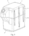
- Figure 1 shows a perspective view of a reducing agent tank T for a reducing agent, in particular a urea tank for a preferably aqueous urea solution, for. B. AdBlue.
- Figure 2 shows another perspective view of the reducing agent tank T of Figure 1 with an illustrative omission, so that the reducing agent tank T can be viewed for illustration purposes.
- the reducing agent tank T comprises a housing 1 comprising two housing sections 1.1 and 1.2, which are mounted to one another, for receiving the reducing agent, a delivery module 2 for delivering the reducing agent, and a tank segment 3 arranged under the housing 1.
- the reducing agent tank T is used for mounting on a motor vehicle, preferably a commercial vehicle , especially a truck or an omnibus.
- the tank segment 3 is provided with an integrated fluid channel 3.1 for guiding a fluid for heating the reducing agent, so that the tank segment 3 itself forms the fluid channel 3.1.
- the tank segment 3 and the fluid channel 3.1 are thus formed by one and the same molded part, preferably an injection molded part.
- the tank segment 3 is produced in such a way that the fluid channel 3.1 is integrated, in particular is formed with, for. B. is molded or molded.
- the tank segment 3 comprises a flat, suitably hood-shaped wall 3.3, on the inside of which the fluid channel 3.1 is formed.
- the sheet-like wall 3.3 expediently forms a lower end cover for the housing 1.
- the tank segment 3 forms a boundary structure 3.2 for the fluid channel 3.1.
- the delimiting structure 3.2 delimits the fluid channel 3.1 along its longitudinal extent L.
- the delimiting structure 3.2 comprises two essentially parallel wall elements 3.2 and an inside part of the sheet-like wall 3.3.
- the two wall elements 3.2 laterally limit the fluid channel 3.1.
- the sheet-like wall 3.3 delimits the fluid channel 3.1 downwards.
- the tank segment 3 in particular the delimitation structure 3.2 and 3.3, leaves the fluid channel 3.1 open on one side, namely in Figure 2 towards the top.
- the open side so in Figure 2 the top, and thus the fluid channel 3.1, is closed in the assembled state of the reducing agent tank T by an adjacent tank element, namely in Figure 2 through a base segment, expediently a base plate, of the housing 1.
- the tank segment 3 further comprises a receiving opening for the delivery module 2 for delivering the reducing agent, so that the delivery module 2 is expediently integrated into the tank segment 3.
- the fluid channel 3.1 extends at least in sections essentially in a circular arc and in a meandering shape around the receiving opening and thus around the delivery module 2.
- the tank segment 3 comprises a fluid channel inlet 3.4 and a fluid channel outlet 3.5.
- the fluid channel 3.1 is used for connection to a line for cooling fluid for cooling an internal combustion engine (for example an internal combustion engine, gasoline engine, etc.) of a motor vehicle Figures 1 and 2 it can be seen that the tank segment 3 serves as a floor cover and at the same time as a floor heater for the housing 1 and thus the reducing agent.
- an internal combustion engine for example an internal combustion engine, gasoline engine, etc.
- FIGS. 3 and 4 show different perspective views of a tank segment 3 according to an embodiment of the invention, which is identical to the tank segment 3 of FIG Figures 1 and 2 is executed.
- the tank segment 3 is provided with an integrated fluid channel 3.1 and the tank segment 3 including the fluid channel 3.1 is formed by one and the same molded part.
- the fluid channel 3.1 is therefore expediently an integral part of the tank segment 3.
- the fluid channel 3.1 is formed on the inside of the sheet-like wall 3.3 and is in the assembled state of the reducing agent tank 3 along its longitudinal extension L below by part of the sheet-like wall 3.3, laterally by the two essentially parallel wall elements 3.2 and above by a bottom segment of the housing 1 limited.
- the fluid channel 3.1 runs in an arcuate and meandering manner around the receiving opening for the delivery module 2.
- the tank segment 3 further comprises a plurality of stiffening ribs, in particular for stiffening the sheet-like wall 3.3.
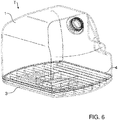
- Figure 5 shows an exploded view of a reducing agent tank T according to another embodiment of the invention while Figure 6 an associated perspective view of the reducing agent tank T shows.
- the design of the tank element 4 represents a special feature.
- the preferably plate-shaped tank element 4 is arranged between the housing 1 and the tank segment 3, serves to close the fluid channel 3.1 towards the top and serves to separate and at the same time contact the reducing agent in the housing 1 and the fluid in the tank segment 3, in particular in the fluid channel 3.1.
- the tank element 4 is formed from plastic material, which is additized with at least one filler material (e.g. filler, additive and / or additive), so that the filler material is expediently embedded in the plastic material, in particular is admixed with the same.
- the filler material serves to increase the thermal conductivity of the plastic material, so that the heat of the fluid from the fluid channel 3.1 can be transferred more effectively to the reducing agent in the housing 1.
- the addition of the filler material to the plastic material is expediently carried out during the manufacturing process of the tank element 4.
- the thermal conductivity of the plastic material of the tank element 4 can be increased by proportionally admixing / additizing the filler material, so that the heat output of the tank segment 3 can expediently be increased.
- the plastic material and / or its filler material must be urea-resistant.
- the filler material may also not be urea-resistant if it is appropriately incorporated into the plastic. In this case, the filler material must be manufactured by appropriate manufacturing z. B. completely enclosed by plastic material so as not to have any contact with the urea.
- the filler material can e.g. B. include boron nitride, which on the one hand leads to an improvement in the thermal conductivity of the plastic material and on the other hand is urea-resistant.
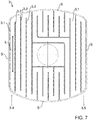
- Figure 7 shows a top view of the tank segment 3 of FIG Figures 5 and 6
- Figure 8 shows an associated perspective view of the tank segment 3.
- the fluid channel 3.1 is delimited along its longitudinal extent L by means of a delimiting structure 3.2 formed by the tank segment 3.
- the delimiting structure 3.2 includes the side outer walls S of the tank segment 3.
- the delimiting structure 3.2 does not include, as in the embodiment of FIG Figures 1 to 4 only one pair of wall elements, the wall elements of which extend continuously over the tank segment 3, but a plurality of pairs of wall elements, the wall elements of which overlap in sections, extend in opposite directions and expediently discontinuously.
- the wall element pairs produce a change in fluid channel direction at their longitudinal ends by essentially 180 °.
Landscapes
- Chemical & Material Sciences (AREA)
- Engineering & Computer Science (AREA)
- Chemical Kinetics & Catalysis (AREA)
- Health & Medical Sciences (AREA)
- Toxicology (AREA)
- Combustion & Propulsion (AREA)
- Mechanical Engineering (AREA)
- General Engineering & Computer Science (AREA)
- Exhaust Gas After Treatment (AREA)
Description
- Die Erfindung betrifft einen Reduktionsmitteltank für ein Reduktionsmittel und zweckmäßig zur Montage an ein Kraftfahrzeug, insbesondere einen Harnstofftank für eine wässrige Harnstofflösung .
- Die
DE 10 2012 109 675 A1 offenbart eine Vorrichtung zur Bereitstellung eines flüssigen Additivs, aufweisend einen Montagegrundkörper, an dem mindestens eine hydraulische Komponente zum Betrieb der Vorrichtung montiert ist, und eine Steckplatte, die an dem Montagegrundkörper befestigt ist und an der mindestens eine elektrische Heizung und mindestens eine weitere elektrische Komponente zum Betrieb der Vorrichtung montiert sind, wobei die mindestens eine elektrische Heizung sich ausgehend von der Steckplatte in mindestens eine Aussparung des Montagegrundkörpers hinein erstreckt. Zum allgemeinen Stand der Technik sind noch dieDE 10 2012 02 040 A1 , dieDE 203 14 557 U1 , dieDE 20 2005 019 499 U1 , dieDE 10 2010 029 269 A1 , dieDE 102 31 624 A1, Günther Pflug et al: "Additive - Nanoskalige Füllstoffe", Kunststoffe 12/2009,US 2013/000743 A1 undEP 2 733 321 A1 zu nennen. Kraftfahrzeug-Reduktionsmitteltanks zur Aufnahme eines Reduktionsmittels sind im Stand der Technik in den unterschiedlichsten Ausführungsformen bekannt. So offenbart z. B.DE 10 2011 108 213 A1 einen beheizbaren Reduktionsmitteltank, der über elektrische Heizelemente beheizbar ist und dessen Reduktionsmittel über ein Tank-externes Fördermodul befördert werden kann. - Eine Aufgabe der Erfindung ist es, einen alternativen und/oder verbesserten Reduktionsmitteltank für ein Reduktionsmittel zu schaffen.
- Diese Aufgabe kann mit den Merkmalen der unabhängigen Ansprüche gelöst werden. Vorteilhafte Weiterbildungen der Erfindung können den Unteransprüchen und der folgenden Beschreibung bevorzugter Ausführungsformen der Erfindung entnommen werden.
- Die Erfindung schafft einen Reduktionsmitteltank für ein Reduktionsmittel, vorzugsweise einen Harnstofftank zur Aufnahme einer wässrigen Harnstofflösung, z. B. eines Harnstoff-Wasser-Gemischs.
- Der Reduktionsmitteltank dient zweckmäßig zur Montage an ein Kraftfahrzeug, vorzugsweise Nutzfahrzeug, insbesondere Lastkraftwagen oder Omnibus.
- Das Reduktionsmittel dient insbesondere zur Versorgung eines Abgasreinigungssystems, z. B. eines auf Basis der katalytischen Reduktion arbeitenden Abgasreinigungssystems.
- Der Reduktionsmitteltank umfasst ein Gehäuse zur Aufnahme des Reduktionsmittels, ein Tanksegment und vorzugsweise ein Fördermodul, z. B. eine Pumpe, zum Fördern des Reduktionsmittels.
- Das Tanksegment zeichnet sich insbesondere dadurch aus, dass es zumindest einen integrierten, insbesondere an- oder eingeformten, Fluidkanal zum Führen eines Fluides zum Erwärmen, insbesondere zum Heizen, des Reduktionsmittels aufweist, vorzugsweise so, dass das Tanksegment selbst den Fluidkanal ausbildet. Der Fluidkanal ist somit vorzugsweise einstückig-integraler Teil des Tanksegments.
- Der Fluidkanal ist somit insbesondere kein zum Tanksegment separates Rohr oder Schlauch.
- Das Tanksegment wird, zweckmäßig in seiner Herstellung bzw. herstellungsbedingt, vorzugsweise so ausgeführt, dass der Fluidkanal mit integriert wird, insbesondere mit ausgeformt wird, z. B. ein- oder angeformt wird.
- Es ist möglich, dass ein und dasselbe Formteil das Tanksegment und den Fluidkanal ausbildet.
- Das Tanksegment und/oder das Formteil sind vorzugsweise ein Spritzgussteil und somit zweckmäßig aus einem Kunststoffmaterial gefertigt.
- Der Fluidkanal ist zweckmäßig auf der Innenseite des Tanksegments ausgebildet.
- Es ist möglich, dass das Tanksegment das Fördermodul aufweist und somit zweckmäßig das Fördermodul in das Tanksegment integriert ist. Hierzu kann das Tanksegment insbesondere eine Aufnahmeöffnung für das Fördermodul aufweisen.
- Es ist möglich, dass ein Fluidkanal zumindest abschnittsweise im Wesentlichen geradlinig verläuft und/oder im Wesentlichen bogenförmig, insbesondere im Wesentlichen kreisbogenförmig um die Aufnahmeöffnung für das Fördermodul bzw. das Fördermodul verläuft. Alternativ oder ergänzend kann ein Fluidkanal zumindest abschnittsweise mäanderförmig verlaufen.
- Das Tanksegment umfasst vorzugsweise eine im Wesentlichen hauben- und/oder flächenförmige Wandung, um ein vorzugsweise hauben- und/oder flächenförmiges Bauteil zu schaffen. Die Wandung dient vorzugsweise als untere Abschlussabdeckung für das Gehäuse.
- Das Tanksegment bildet zweckmäßig eine Begrenzungsstruktur für den Fluidkanal, die den Fluidkanal entlang seiner Längserstreckung begrenzt.
- Die Begrenzungsstruktur umfasst vorzugsweise zumindest zwei im Wesentlichen parallel verlaufende, z. B. rippenförmige Wandelemente und einen innenseitigen Teil der hauben- und/oder flächenförmigen Wandung.
- Der Fluidkanal wird somit vorzugsweise durch im Wesentlichen parallel verlaufende Wandelemente und einen Teil der hauben- und/oder flächenförmigen Wandung begrenzt.
- Es ist möglich, dass das Tanksegment und/oder die Begrenzungsstruktur den Fluidkanal zu einer Seite hin offen lässt und die Seite und somit der Fluidkanal durch ein benachbartes Tankelement geschlossen wird.
- Vorzugsweise lässt das Tanksegment den Fluidkanal zur Oberseite hin offen, wobei die Oberseite und somit der Fluidkanal durch ein aufgesetztes Tankelement, insbesondere ein Bodensegment, z. B. eine Bodenplatte, des Gehäuses geschlossen wird.
- Das Tanksegment ist vorzugsweise unter einem Bodensegment des Gehäuses angeordnet. Das Tanksegment dient insbesondere als Bodenheizung für das Gehäuse.
- Das Tanksegment kann einen Fluidkanal-Einlass und/oder einen Fluidkanal-Auslass aufweisen.
- Der Fluidkanal dient vorzugsweise zur Verbindung mit einem Kühlkreislauf einer Verbrennungskraftmaschine des Kraftfahrzeugs. Hierzu kann das Tanksegment z. B. einen Fluidkanal-Einlass und/oder einen Fluidkanal-Auslass aufweisen.
- Der Fluidkanal ist vorzugsweise ein Heizkanal.
- Ziel ist, dass ein möglichst großer Bereich des Tanksegments durch das Fluid anströmbar und somit erwärmbar ist und/oder eine möglichst maximale Ausnutzung der zur Verfügung stehenden Heizfläche des Tanksegments gepaart mit konstruktiv möglichst maximaler Länge des Fluidkanals.
- Das Fluid kann z. B. Verbrennungskraftmaschinen-Kühlflüssigkeit sein.
- Es ist möglich, dass der Fluidkanal mittels einer durch das Tanksegment gebildeten Begrenzungsstruktur begrenzt wird und die Begrenzungsstruktur z. B. eine Seitenaußenwand oder mehrere Seitenaußenwände des Tanksegments umfasst.
- Der zumindest eine Fluidkanal kann zumindest abschnittsweise im Wesentlichen geradlinig verlaufen, z. B. um die Aufnahmeöffnung für das Fördermodul.
- Es ist möglich, dass zumindest ein Fluidkanal mäanderförmig, labyrinthförmig und/oder schneckenförmig verläuft.
- Die Begrenzungsstruktur für den Fluidkanal kann ein Wandelement-Paar umfassen, dessen Wandelemente sich zweckmäßig im Wesentlichen parallel und/oder vorzugsweise kontinuierlich über das Tanksegment erstrecken, so dass insbesondere der mäanderförmige Fluidkanalverlauf gebildet werden kann. Die Begrenzungsstruktur kann alternativ oder ergänzend eine Vielzahl, z. B. mehr als zwei, mehr als vier oder sogar mehr als sechs, zweckmäßig im Wesentlichen parallel erstreckende Wandelement-Paare umfassen. Die Wandelemente der Wandelement-Paare überlappen sich zweckmäßig abschnittsweise und/oder können sich in gegenläufige, insbesondere entgegengesetzte Richtungen erstrecken. Die Wandelement-Paare erzeugen zweckmäßig an deren Längsenden einen Fluidkanal-Richtungswechsel, z. B. um im Wesentlichen 180°. Dadurch kann insbesondere ein labyrintförmiger Fluidkanal-Verlauf realisiert werden.
- Die Wandelemente sind vorzugsweise rippenförmig ausgebildet.
- Dadurch, dass der Fluidkanal maänderförmig, schneckenförmig und/oder labyrinthförmig ausgeführt sein kann, kann vorzugsweise ermöglicht werden, dass sich der Fluidkanal über einen Großteil der Grundfläche des Tanksegments erstreckt, vorzugsweise über zumindest nahezu die gesamte Grundfläche des Tanksegments, z. B. über über 80% oder sogar 90% der Grundfläche des Tanksegments, zweckmäßig mit Ausnahme der Aufnahmeöffnung für das Fördermodul.
- Es ist möglich, dass zwischen dem Gehäuse und dem Tanksegment ein Tankelement aus Kunststoffmaterial angeordnet ist.
- Im Rahmen der Erfindung kann der Fluidkanal vorzugsweise zur Oberseite hin durch ein zweckmäßig aufgesetztes Tankelement vervollständigt und/oder geschlossen werden. Z. B. entsteht ein vollständiger, zur Oberseite hin geschlossener und/oder betriebsfähiger Fluidkanal insbesondere erst durch ein zweckmäßig aufgesetztes Tankelement, vorzugsweise, wenn das Tanksegment und das Tankelement gefügt sind.
- Das Tankelement ist erfindungsgemäß aus Kunststoffmaterial ausgebildet. Die Wärmeleitfähigkeit von Kunststoffmaterial ist allerdings relativ gering, z. B. im Vergleich zu Aluminium oder Stahl. Durch die Wahl des Werkstoffs Kunststoff wird die Heizleistung des Tanksegments verringert.
- Um diesen Nachteil zu reduzieren, ist das Kunststoffmaterial erfindungsgemäß mit zumindest einem Zusatzwerkstoff (z. B. Additiv, Füllstoff und/oder Zusatzstoff) additiviert, so dass zweckmäßig der Zusatzwerkstoff in das Kunststoffmaterial eingelagert ist. Der Zusatzwerkstoff ist dem Kunststoffmaterial zugesetzt, um zweckmäßig die Wärmeleitfähigkeit des Kunststoffmaterials und somit des Tankelements zu erhöhen.
- Die Zugabe des Zusatzwerkstoffs erfolgt zweckmäßig während des Herstellprozesses des Tankelements durch Additivierung des Zusatzwerkstoffs zum Kunststoffmaterial.
- Durch anteilige Additivierung kann die Wärmeleitfähigkeit des Kunststoffmaterials des Tankelements dementsprechend erhöht werden, so dass zweckmäßig die Heizleistung des Tanksegments über das Tankelement auf das Reduktionsmittel im Gehäuse steigerbar ist.
- Der zur Verbesserung/Erhöhung der Wärmeleitfähigkeit dienende Zusatzwerkstoff kann zumindest ein Additiv umfassen, z. B. Bornitrid.
- Es ist möglich, dass das Tankelement zur Trennung und/oder Kontaktierung des Reduktionsmittels im Gehäuse und des Fluids im Tanksegment ausgebildet ist. Dadurch kann z. B. ein Vermischen des Reduktionsmittels im Gehäuse und des Fluids im Tanksegment vermieden werden.
- Das Kunststoffmaterial und/oder der Zusatzwerkstoff sind vorzugsweise Harnstoff-resistent.
- Es ist möglich, dass der Zusatzwerkstoff in das Kunststoffmaterial eingearbeitet (z. B. eingeschlossen, eingebettet, etc.) ist, um nicht mit dem Reduktionsmittel, insbesondere Harnstoff, in Kontakt zu kommen. In diesem Fall bedeckt das Kunststoffmaterial zweckmäßig herstellungsbedingt den Zusatzwerkstoff, so dass der Zusatzwerkstoff vom Reduktionsmittel isoliert wird und somit zweckmäßig mit dem Reduktionsmittel nicht in Kontakt gelangen kann. Z. B. kann der Zusatzwerkstoff mittels entsprechender Herstellung durch Kunststoffmaterial im Wesentlichen vollständig umschlossen sein. Der Zusatzwerkstoff muss also nicht zwingend Reduktionsmittel-resistent, insbesondere Harnstoff-resistent, sein.
- Das Tankelement ist vorzugsweise plattenförmig ausgebildet, z. B. als Gehäusebodenplatte und/oder Tanksegmentdeckenplatte.
- Das Tankelement kann mit dem Gehäuse und/oder dem Tanksegment gefügt sein, z. B. durch Kleben oder Schweißen.
- Der Reduktionsmitteltank kann eine elektrische Heizeinrichtung zum Erwärmen des Reduktionsmittels im Gehäuse aufweisen, insbesondere zusätzlich zum als Bodenheizung wirkenden Tanksegment.
- Das Tanksegment kann ferner mehrere Versteifungsrippen aufweisen, insbesondere zur Aussteifung und somit zweckmäßigen Verstärkung der hauben- und/oder flächenförmigen Wandung.
- Die Erfindung ist nicht auf einen Reduktionsmitteltank begrenzt, sondern umfasst auch ein Tanksegment wie hierin offenbart.
- Des Weiteren umfasst die Erfindung ein Kraftfahrzeug, vorzugsweise ein Nutzfahrzeug, insbesondere einen Omnibus oder einen Lastkraftwagen, mit einem Reduktionsmitteltank wie hierin offenbart.
- Das Kraftfahrzeug umfasst vorzugsweise ein Abgasnachbehandlungssystem, das mit dem Reduktionsmittel aus dem Reduktionsmitteltank versorgt werden kann.
- Die zuvor beschriebenen bevorzugten Ausführungsformen und Merkmale der Erfindung sind miteinander kombinierbar. Andere vorteilhafte Weiterbildungen sind in den Unteransprüchen offenbart oder ergeben sich aus der folgenden Beschreibung bevorzugter Ausführungsformen der Erfindung in Verbindung mit den beigefügten Figuren.
- Figur 1
- zeigt eine perspektivische Ansicht eines Reduktionsmitteltanks gemäß einer Ausführungsform der Erfindung,
- Figur 2
- zeigt eine andere perspektivische Ansicht des Reduktionsmitteltanks der
Figur 1 mit einer illustrativen Weglassung, so dass zu Illustrationszwecken in den Reduktionsmitteltank hineingeschaut werden kann, - Figur 3
- zeigt eine perspektivische Ansicht eines Tanksegments gemäß einer Ausführungsform der Erfindung,
- Figur 4
- zeigt eine andere perspektivische Ansicht des Tanksegments der
Figur 3 , - Figur 5
- zeigt eine explosionsartige Schnittansicht eines Reduktionsmitteltanks gemäß einer Ausführungsform der Erfindung,
- Figur 6
- zeigt eine perspektivische Ansicht des Reduktionsmitteltanks der
Figur 5 , - Figur 7
- zeigt eine Draufsicht auf ein Tanksegment gemäß einer Ausführungsform der Erfindung, und
- Figur 8
- zeigt eine perspektivische Ansicht des Tanksegments der
Figur 7 . - Die in den Figuren gezeigten Ausführungsformen stimmen teilweise überein, so dass ähnliche oder identische Teile mit den gleichen Bezugszeichen versehen sind, und zu deren Erläuterung auch auf die Beschreibung der anderen Ausführungsformen bzw. Figuren verwiesen wird, um Wiederholungen zu vermeiden.
-
Figur 1 zeigt eine perspektivische Ansicht eines Reduktionsmitteltanks T für ein Reduktionsmittel, insbesondere einen Harnstofftank für eine vorzugsweise wässrige Harnstofflösung, z. B. sogenanntem AdBlue.Figur 2 zeigt eine andere perspektivische Ansicht des Reduktionsmitteltanks T derFigur 1 mit einer illustrativen Weglassung, so dass zu Illustrationszwecken in den Reduktionsmitteltank T hineingeschaut werden kann. - Unter Bezugnahme auf die
Figuren 1 und2 umfasst der Reduktionsmitteltank T ein Gehäuse 1 aus zwei aneinander montierten Gehäuseabschnitten 1.1 und 1.2 zur Aufnahme des Reduktionsmittels, ein Fördermodul 2 zum Fördern des Reduktionsmittels und ein unter dem Gehäuse 1 angeordnetes Tanksegment 3. Der Reduktionsmitteltank T dient zur Montage an ein Kraftfahrzeug, vorzugsweise ein Nutzfahrzeug, insbesondere ein Lastkraftwagen oder einen Omnibus. - Das Tanksegment 3 ist mit einem integrierten Fluidkanal 3.1 zum Führen eines Fluids zum Erwärmen des Reduktionsmittels versehen, so dass das Tanksegment 3 selbst den Fluidkanal 3.1 ausbildet. Das Tanksegment 3 und der Fluidkanal 3.1 werden somit durch ein und dasselbe Formteil, vorzugsweise ein Spritzgussteil ausgebildet. Das Tanksegment 3 wird in seiner Herstellung so ausgeführt, dass der Fluidkanal 3.1 mit integriert wird, insbesondere mit ausgeformt wird, z. B. ein- oder angeformt wird.
- Das Tanksegment 3 umfasst eine flächenförmige, zweckmäßig haubenförmige Wandung 3.3, an deren Innenseite der Fluidkanal 3.1 ausgebildet ist. Die flächenförmige Wandung 3.3 bildet zweckmäßig eine untere Abschlussabdeckung für das Gehäuse 1.
- Das Tanksegment 3 bildet eine Begrenzungsstruktur 3.2 für den Fluidkanal 3.1. Die Begrenzungsstruktur 3.2 begrenzt den Fluidkanal 3.1 entlang seiner Längserstreckung L. Die Begrenzungsstruktur 3.2 umfasst zwei im Wesentlichen parallel verlaufende Wandelemente 3.2 und einen innenseitigen Teil der flächenförmigen Wandung 3.3. Die zwei Wandelemente 3.2 begrenzen den Fluidkanal 3.1 seitlich. Die flächenförmige Wandung 3.3 begrenzt den Fluidkanal 3.1 nach unten.
- Das Tanksegment 3, insbesondere die Begrenzungsstruktur 3.2 und 3.3, lässt den Fluidkanal 3.1 zu einer Seite hin offen, nämlich in
Figur 2 zur Oberseite hin. Die offene Seite, also inFigur 2 die Oberseite, und somit der Fluidkanal 3.1 wird im Montagezustand des Reduktionsmitteltanks T durch ein benachbartes Tankelement geschlossen, nämlich inFigur 2 durch ein Bodensegment, zweckmäßig eine Bodenplatte, des Gehäuses 1. - Das Tanksegment 3 umfasst ferner eine Aufnahmeöffnung für das Fördermodul 2 zum Fördern des Reduktionsmittels, so dass das Fördermodul 2 zweckmäßig in das Tanksegment 3 integriert ist. Der Fluidkanal 3.1 erstreckt sich zumindest abschnittsweise im Wesentlichen kreisbogenförmig und mäanderförmig um die Aufnahmeöffnung und somit um das Fördermodul 2.
- Das Tanksegment 3 umfasst einen Fluidkanal-Einlass 3.4 und einen Fluidkanal-Auslass 3.5.
- Der Fluidkanal 3.1 dient zur Verbindung mit einer Leitung für Kühlfluid zum Kühlen einer Verbrennungskraftmaschine (z. B. einem Verbrennungsmotor, Ottomotor, etc.) eines Kraftfahrzeugs Aus den
Figuren 1 und2 wird ersichtlich, dass das Tanksegment 3 als Bodenabdeckung und zugleich als Bodenheizung für das Gehäuse 1 und somit das Reduktionsmittel dient. - Die
Figuren 3 und4 zeigen unterschiedliche perspektivische Ansichten eines Tanksegments 3 gemäß einer Ausführungsform der Erfindung, das identisch zu dem Tanksegment 3 derFiguren 1 und2 ausgeführt ist. - Aus den
Figuren 3 und4 wird insbesondere nochmals ersichtlich, dass das Tanksegment 3 mit einem integrierten Fluidkanal 3.1 versehen ist und das Tanksegment 3 einschließlich des Fluidkanals 3.1 durch ein und dasselbe Formteil ausgebildet wird. Der Fluidkanal 3.1 ist somit zweckmäßig einstückig-integraler Teil des Tanksegments 3. - Der Fluidkanal 3.1 ist auf der Innenseite der flächenförmigen Wandung 3.3 ausgebildet und wird im Montagezustand des Reduktionsmitteltanks 3 entlang seiner Längserstreckung L unten durch einen Teil der flächenförmigen Wandung 3.3, seitlich durch die zwei im Wesentlichen parallel verlaufenden Wandelemente 3.2 und oben durch ein Bodensegment des Gehäuses 1 begrenzt. Der Fluidkanal 3.1 verläuft bogen- und mäanderförmig um die Aufnahmeöffnung für das Fördermodul 2.
- Das Tanksegment 3 umfasst ferner mehrere Versteifungsrippen, insbesondere zur Aussteifung der flächenförmigen Wandung 3.3.
-
Figur 5 zeigt eine explosionsartige Ansicht eines Reduktionsmitteltanks T gemäß einer anderen Ausführungsform der Erfindung, währendFigur 6 eine zugehörige perspektivische Ansicht des Reduktionsmitteltanks T zeigt. - Unter Bezugnahme auf die
Figuren 5 und6 stellt zunächst insbesondere die Ausführung des Tankelements 4 eine Besonderheit dar. Das vorzugsweise plattenförmige Tankelement 4 ist zwischen dem Gehäuse 1 und dem Tanksegment 3 angeordnet, dient zur Schließung des Fluidkanals 3.1 zur Oberseite hin und dient zur Trennung und zugleich zur Kontaktierung des Reduktionsmittels im Gehäuse 1 und des Fluids im Tanksegment 3, insbesondere im Fluidkanal 3.1. - Das Tankelement 4 ist aus Kunststoffmaterial ausgebildet, das mit zumindest einem Zusatzwerkstoff (z. B. Füllstoff, Additiv und/oder Zusatzstoff) additiviert ist, so dass zweckmäßig der Zusatzwerkstoff in das Kunststoffmaterial eingelagert ist, insbesondere selbigem beigemischt ist. Der Zusatzwerkstoff dient zur Steigerung der Wärmeleitfähigkeit des Kunststoffmaterials, so dass die Wärme des Fluids aus dem Fluidkanal 3.1 effektiver auf das Reduktionsmittel im Gehäuse 1 übertragbar ist. Die Zugabe des Zusatzwerkstoffs zum Kunststoffmaterial erfolgt zweckmäßig während des Herstellprozesses des Tankelements 4. Durch anteilige Beimischung/Additivierung des Zusatzwerkstoffs kann die Wärmeleitfähigkeit des Kunststoffmaterials des Tankelements 4 erhöht werden, so dass zweckmäßig die Heizleistung des Tanksegments 3 steigerbar ist.
- Weil das Tankelement 4 mit dem Harnstoff umfassenden Reduktionsmittel im Gehäuse 1 in Kontakt kommt, muss das Kunststoffmaterial und/oder dessen Zusatzwerkstoff Harnstoff-resistent sein. Der Zusatzwerkstoff kann durch entsprechende Einarbeitung in den Kunststoff gegebenenfalls auch nicht Harnstoff-resistent sein. In diesem Fall muss der Zusatzwerkstoff durch entsprechende Herstellung z. B. vollständig durch Kunststoffmaterial umschlossen sein, um keinen Kontakt zum Harnstoff aufzuweisen.
- Der Zusatzwerkstoff kann z. B. Bornitrid umfassen, das einerseits zu einer Wärmeleitfähigkeitsverbesserung des Kunststoffmaterials führt und andererseits Harnstoff-resistent ist.
- Eine weitere Besonderheit der in den
Figuren 5 und6 gezeigten Ausführungsform ist der labyrinthförmige Fluidkanal 3.1. -
Figur 7 zeigt eine Draufsicht auf das Tanksegment 3 derFiguren 5 und6 , währendFigur 8 eine zugehörige perspektivische Ansicht des Tanksegments 3 zeigt. - Den
Figuren 7 und8 kann insbesondere der labyrinthförmige Verlauf des Fluidkanals 3.1 entnommen werden. - Der Fluidkanal 3.1 wird mittels einer durch das Tanksegment 3 gebildeten Begrenzungsstruktur 3.2 entlang seiner Längserstreckung L begrenzt. Die Begrenzungsstruktur 3.2 umfasst zusätzlich zu der Wandung 3.3 die Seitenaußenwände S des Tanksegments 3.
- Die Begrenzungsstruktur 3.2 umfasst nicht wie in der Ausführungsform der
Figuren 1 bis 4 nur ein Wandelement-Paar, dessen Wandelemente sich kontinuierlich über das Tanksegment 3 erstrecken, sondern eine Vielzahl an Wandelement-Paaren, deren Wandelemente sich abschnittsweise überlappen, sich gegenläufig und zweckmäßig diskontinuierlich erstrecken. Die Wandelement-Paare erzeugen an deren Längsenden einen Fluidkanal-Richtungswechsel um im Wesentlichen 180°. - Dadurch kann ermöglicht werden, dass sich der Fluidkanal 3.1 über die im Wesentlichen gesamte Grundfläche des Tanksegments 3 labyrinthförmig erstreckt, mit Ausnahme der Aufnahmeöffnung für das Fördermodul 2, so dass ein möglichst großer Bereich des Tanksegments 3 durch das Fluid anströmbar und somit erwärmbar ist bzw. eine maximale Ausnutzung der zur Verfügung stehenden Heizfläche des Tanksegments 3 gepaart mit konstruktiv maximaler Länge des Fluidkanals 3.1 erfolgt.
-
- T
- Reduktionsmitteltank, insbesondere Harnstofftank
- 1
- Gehäuse
- 1.1
- Gehäuseabschnitt
- 1.2
- Gehäuseabschnitt
- 2
- Fördermodul zum Fördern des Reduktionsmittels
- 3
- Tanksegment, z. B. Heizelement
- 3.1
- Fluidkanal, insbesondere Heizkanal zum Führen eines Fluides zum Erwärmen des Reduktionsmittels
- 3.2
- Begrenzungsstruktur für den Fluidkanal, insbesondere seitliche Begrenzungsstruktur
- 3.3
- Hauben- und/oder flächenförmige Wandung
- 3.4
- Fluidkanal-Einlass
- 3.5
- Fluidkanal-Auslass
- 4
- Tankelement, insbesondere zur Anordnung zwischen Gehäuse und Tanksegment
- S
- Seitenaußenwände des Tanksegments
- L
- Längserstreckung, insbesondere Längsrichtung, des Fluidkanals
Claims (22)
- Reduktionsmitteltank (T) für ein Reduktionsmittel und vorzugsweise zur Montage an ein Kraftfahrzeug, mit einem Gehäuse (1) zur Aufnahme des Reduktionsmittels, einem Tanksegment (3) und vorzugsweise einem Fördermodul (2) zum Fördern des Reduktionsmittels, und einem Tankelement (4) aus Kunststoffmaterial, dadurch gekennzeichnet, dass das Kunststoffmaterial mit zumindest einem Zusatzwerkstoff zur Erhöhung der Wärmeleitfähigkeit additiviert ist.
- Reduktionsmitteltank (T) nach Anspruch 1, dadurch gekennzeichnet, dass ein und dasselbe Formteil das Tanksegment (3) und einen Fluidkanal (3.1) ausbildet.
- Reduktionsmitteltank (T) nach einem der vorhergehenden Ansprüche, dadurch gekennzeichnet, dass das Tanksegment (3) und/oder das Formteil ein Spritzgussteil sind.
- Reduktionsmitteltank (T) nach einem der vorhergehenden Ansprüche, dadurch gekennzeichnet, dass der Fluidkanal (3.1) auf einer Innenseite des Tanksegments (3) ausgebildet ist.
- Reduktionsmitteltank (T) nach einem der vorhergehenden Ansprüche, dadurch gekennzeichnet, dass das Tanksegment (3) das Fördermodul (2) aufweist und/oder eine Aufnahmeöffnung für das Fördermodul (2) aufweist.
- Reduktionsmitteltank (T) nach einem der vorhergehenden Ansprüche, dadurch gekennzeichnet, dass zumindest ein Fluidkanal (3.1) zumindest abschnittsweise bogenförmig um die Aufnahmeöffnung für das Fördermodul (2) und/oder zumindest abschnittsweise geradlinig verläuft.
- Reduktionsmitteltank (T) nach einem der vorhergehenden Ansprüche, dadurch gekennzeichnet, dass das Tanksegment (3) eine hauben- und/oder flächenförmige Wandung (3.3) umfasst und die Wandung (3.3) eine vorzugsweise untere Abschlussabdeckung für das Gehäuse (1) bildet.
- Reduktionsmitteltank (T) nach einem der vorhergehenden Ansprüche, dadurch gekennzeichnet, dass der Fluidkanal (3.1) mittels einer durch das Tanksegment (3) gebildeten Begrenzungsstruktur (3.2) entlang seiner Längserstreckung (L) begrenzt wird.
- Reduktionsmitteltank (T) nach einem der vorhergehenden Ansprüche, dadurch gekennzeichnet, dass das Tanksegment (3) und/oder die Begrenzungsstruktur (3.2) den Fluidkanal (3.1) zu einer Seite hin offen lässt und die Seite und somit der Fluidkanal (3.1) durch ein benachbartes Tankelement (4) geschlossen wird.
- Reduktionsmitteltank (T) nach einem der vorhergehenden Ansprüche, dadurch gekennzeichnet, dass das Tanksegment (3) und/oder die Begrenzungsstruktur (3.2) den Fluidkanal (3.1) zur Oberseite hin offen lässt und die Oberseite durch ein aufgesetztes Tankelement (4), insbesondere ein Bodensegment des Gehäuses (1), geschlossen wird.
- Reduktionsmitteltank (T) nach einem der vorhergehenden Ansprüche, dadurch gekennzeichnet, dass das Tanksegment (3) unter einem Tankelement (4), insbesondere einem Bodensegment des Gehäuses (1), angeordnet ist und/oder als Bodenheizung für das Gehäuse (1) und somit das Reduktionsmittel dient.
- Reduktionsmitteltank (T) nach einem der vorhergehenden Ansprüche, dadurch gekennzeichnet, dass der Fluidkanal (3.1) mit einem Kühlkreislauf einer Verbrennungskraftmaschine des Kraftfahrzeugs verbindbar ist.
- Reduktionsmitteltank (T) nach einem der vorhergehenden Ansprüche, dadurch gekennzeichnet, dass der Fluidkanal (3.1) mittels einer durch das Tanksegment (3) gebildeten Begrenzungsstruktur (3.2) begrenzt wird und die Begrenzungsstruktur (3.2) eine oder mehrere Seitenaußenwände des Tanksegments (3) umfasst.
- Reduktionsmitteltank (T) nach einem der vorhergehenden Ansprüche, dadurch gekennzeichnet, dass der Fluidkanal (3.1) zumindest abschnittsweise mäanderförmig, labyrinthförmig und/oder schneckenförmig verläuft.
- Reduktionsmitteltank (T) nach einem der vorhergehenden Ansprüche, dadurch gekennzeichnet, dass der Fluidkanal (3.1) mittels einer durch das Tanksegment (3) gebildeten Begrenzungsstruktur (3.2) begrenzt wird und die Begrenzungsstruktur (3.2) ein Wandelement-Paar umfasst, dessen Wandelemente sich kontinuierlich über das Tanksegment (3) erstrecken, oder eine Vielzahl an Wandelement-Paaren umfasst, deren Wandelemente sich abschnittsweise überlappen und sich vorzugsweise gegenläufig erstrecken.
- Reduktionsmitteltank (T) nach einem der vorhergehenden Ansprüche, dadurch gekennzeichnet, dass das Tankelement (4) aus Kunststoffmaterial zwischen dem Gehäuse (1) und dem Tanksegment (3) angeordnet ist.
- Reduktionsmitteltank (T) nach Anspruch 16, dadurch gekennzeichnet, dass das Kunststoffmaterial und/oder der Zusatzwerkstoff Harnstoff-resistent ist.
- Reduktionsmitteltank (T) nach Anspruch 16 oder 17, dadurch gekennzeichnet, dass das Tankelement (4) zur Trennung und/oder Kontaktierung des Reduktionsmittels im Gehäuse (1) und des Fluids im Tanksegment (3) ausgebildet ist.
- Reduktionsmitteltank (T) nach einem der Ansprüche 16 bis 18, dadurch gekennzeichnet, dass der Zusatzwerkstoff Bornitrid umfasst.
- Reduktionsmitteltank (T) nach einem der Ansprüche 16 bis 19 dadurch gekennzeichnet, dass der Zusatzwerkstoff in das Kunststoffmaterial eingearbeitet ist, um vom Reduktionsmittel isoliert zu werden und insbesondere somit mit dem Reduktionsmittel nicht in Kontakt zu kommen.
- Reduktionsmitteltank (T) nach einem der vorhergehenden Ansprüche, dadurch gekennzeichnet, dass der Reduktionsmitteltank (T) eine elektrische Heizeinrichtung zum Erwärmen des Reduktionsmittels im Gehäuse (1) aufweist.
- Kraftfahrzeug, vorzugsweise Nutzfahrzeug, mit einem Reduktionsmitteltank (T) nach einem der Ansprüche 1 bis 21.
Applications Claiming Priority (3)
| Application Number | Priority Date | Filing Date | Title |
|---|---|---|---|
| DE102015008351.1A DE102015008351A1 (de) | 2015-06-27 | 2015-06-27 | Reduktionsmitteltank mit integriertem Fluidkanal zum Führen eines Heizfluides |
| DE102015012625.3A DE102015012625A1 (de) | 2015-09-26 | 2015-09-26 | Reduktionsmitteltank mit integriertem Fluidkanal zum Führen eines Heizfluides |
| EP16001351.2A EP3109425B1 (de) | 2015-06-27 | 2016-06-15 | Reduktionsmitteltank mit integriertem fluidkanal zum führen eines heizfluides |
Related Parent Applications (2)
| Application Number | Title | Priority Date | Filing Date |
|---|---|---|---|
| EP16001351.2A Division-Into EP3109425B1 (de) | 2015-06-27 | 2016-06-15 | Reduktionsmitteltank mit integriertem fluidkanal zum führen eines heizfluides |
| EP16001351.2A Division EP3109425B1 (de) | 2015-06-27 | 2016-06-15 | Reduktionsmitteltank mit integriertem fluidkanal zum führen eines heizfluides |
Publications (2)
| Publication Number | Publication Date |
|---|---|
| EP3399167A1 EP3399167A1 (de) | 2018-11-07 |
| EP3399167B1 true EP3399167B1 (de) | 2020-01-01 |
Family
ID=56235523
Family Applications (2)
| Application Number | Title | Priority Date | Filing Date |
|---|---|---|---|
| EP16001351.2A Active EP3109425B1 (de) | 2015-06-27 | 2016-06-15 | Reduktionsmitteltank mit integriertem fluidkanal zum führen eines heizfluides |
| EP18179743.2A Active EP3399167B1 (de) | 2015-06-27 | 2016-06-15 | Reduktionsmitteltank mit integriertem fluidkanal zum führen eines heizfluides |
Family Applications Before (1)
| Application Number | Title | Priority Date | Filing Date |
|---|---|---|---|
| EP16001351.2A Active EP3109425B1 (de) | 2015-06-27 | 2016-06-15 | Reduktionsmitteltank mit integriertem fluidkanal zum führen eines heizfluides |
Country Status (4)
| Country | Link |
|---|---|
| EP (2) | EP3109425B1 (de) |
| CN (2) | CN106285860A (de) |
| BR (2) | BR122020020091B1 (de) |
| RU (2) | RU2769211C2 (de) |
Families Citing this family (2)
| Publication number | Priority date | Publication date | Assignee | Title |
|---|---|---|---|---|
| IT201800020962A1 (it) * | 2018-12-21 | 2020-06-21 | Officine Metallurgiche G Cornaglia Spa | Serbatoio veicolare per una soluzione di urea e suo metodo di realizzazione |
| CN111577418A (zh) * | 2020-05-28 | 2020-08-25 | 中国船舶工业集团公司第七0八研究所 | 一种fsru上超临界三级级联朗肯循环发电系统 |
Family Cites Families (19)
| Publication number | Priority date | Publication date | Assignee | Title |
|---|---|---|---|---|
| CN86106962A (zh) * | 1986-11-01 | 1988-05-11 | 菲利浦光灯制造公司 | 家用电冰箱铝合金汽化器及其制造方法 |
| DE10231624A1 (de) * | 2002-07-12 | 2004-01-29 | Robert Bosch Gmbh | Piezoelektrisches Bauelement |
| DE20314557U1 (de) * | 2003-09-19 | 2003-11-20 | Sauermann Franz | Behälter für aggressive Flüssigkeiten mit Heiz- und/oder Kühlmöglichkeit |
| DE202005019499U1 (de) * | 2005-12-14 | 2006-02-09 | Man Nutzfahrzeuge Ag | Beheizung eines Tanks für Harnstoffwasserlösung |
| KR100706653B1 (ko) * | 2006-12-27 | 2007-04-13 | 제일모직주식회사 | 열전도성 수지 조성물 및 플라스틱 성형품 |
| CN101261094B (zh) * | 2008-04-24 | 2011-09-07 | 丁宏广 | 一种板式热交换器的用途及外壳包含至少一个该板式热交换器的容器 |
| DE102009000094A1 (de) * | 2009-01-09 | 2010-07-15 | Robert Bosch Gmbh | Tank zur Aufnahme einer wässrigen Lösung |
| DE102010004614A1 (de) * | 2010-01-13 | 2011-07-14 | Emitec Gesellschaft für Emissionstechnologie mbH, 53797 | Tankanordnung und Dosiersystem für ein Reduktionsmittel |
| DE102010005056A1 (de) * | 2010-01-20 | 2011-07-21 | Emitec Gesellschaft für Emissionstechnologie mbH, 53797 | Behälter für eine Flüssigkeit, insbesondere ein Reduktionsmittel |
| DE102010029269A1 (de) * | 2010-05-25 | 2011-12-01 | Robert Bosch Gmbh | Beheizbarer Tankbehälter |
| US20130000743A1 (en) * | 2011-06-29 | 2013-01-03 | Ti Group Automotive Systems, L.L.C. | Scr fluid distribution and circulation system |
| CN102979602B (zh) * | 2011-07-18 | 2015-05-06 | 苏州派格丽减排系统有限公司 | Scr系统还原剂计量与储存装置的液体加热系统 |
| DE102011108213A1 (de) | 2011-07-21 | 2013-01-24 | Audi Ag | Beheizbarer Reduktionsmitteltank |
| DE102012020040B4 (de) * | 2012-10-12 | 2015-04-16 | Kautex Textron Gmbh & Co. Kg | Einrichtung zur Bevorratung und Förderung eines wässrigen Additivs |
| US9415681B2 (en) * | 2012-08-28 | 2016-08-16 | Yapp Automotive Parts Co., Ltd. | Automobile urea tank forming method |
| DE102012109675A1 (de) * | 2012-10-11 | 2014-04-30 | Emitec Denmark A/S | Vorrichtung zur Bereitstellung eines flüssigen Additivs |
| CN202954873U (zh) * | 2012-11-16 | 2013-05-29 | 平凡科技有限公司 | 柴油发动机尾气后处理scr系统用尿素箱 |
| CN203106868U (zh) * | 2012-12-25 | 2013-08-07 | 奥特朗电器(广州)有限公司 | 余热回收式洗漱盆 |
| DE102014200711A1 (de) * | 2014-01-16 | 2015-07-16 | Robert Bosch Gmbh | Vorrichtung und Verfahren zum Beheizen eines Fluids |
-
2016
- 2016-06-15 EP EP16001351.2A patent/EP3109425B1/de active Active
- 2016-06-15 EP EP18179743.2A patent/EP3399167B1/de active Active
- 2016-06-24 RU RU2020107305A patent/RU2769211C2/ru active
- 2016-06-24 RU RU2016125220A patent/RU2721065C2/ru active
- 2016-06-27 BR BR122020020091-0A patent/BR122020020091B1/pt active IP Right Grant
- 2016-06-27 CN CN201610475356.XA patent/CN106285860A/zh active Pending
- 2016-06-27 BR BR102016015053-1A patent/BR102016015053B1/pt active IP Right Grant
- 2016-06-27 CN CN201911394656.5A patent/CN111075542A/zh active Pending
Non-Patent Citations (1)
| Title |
|---|
| None * |
Also Published As
| Publication number | Publication date |
|---|---|
| CN111075542A (zh) | 2020-04-28 |
| RU2016125220A (ru) | 2017-12-26 |
| BR122020020091B1 (pt) | 2023-01-31 |
| RU2020107305A (ru) | 2020-03-26 |
| CN106285860A (zh) | 2017-01-04 |
| EP3109425B1 (de) | 2018-08-15 |
| EP3399167A1 (de) | 2018-11-07 |
| RU2721065C2 (ru) | 2020-05-15 |
| BR102016015053A2 (pt) | 2017-07-25 |
| RU2769211C2 (ru) | 2022-03-29 |
| BR102016015053B1 (pt) | 2023-02-14 |
| EP3109425A1 (de) | 2016-12-28 |
| RU2020107305A3 (de) | 2022-01-26 |
Similar Documents
| Publication | Publication Date | Title |
|---|---|---|
| EP1893852B1 (de) | Reduktionsmittelversorgungssystem für einen abgasreinigungskatalysator und heizeinrichtung hierfür | |
| EP2010768B1 (de) | Beheizbares schlauchleitungssystem für abgasnachbehandlungsanlagen von brennkraftmaschinen | |
| EP2577012B1 (de) | Beheizbare fluidentnahmevorrichtung | |
| DE102005037201A1 (de) | Heizsystem | |
| DE102007050272A1 (de) | Tank zur Bevorratung eines Reduktionsmittels | |
| KR20150054872A (ko) | 작동 유체용 플라스틱 탱크 | |
| EP3152422A1 (de) | Vorrichtung zur bereitstellung eines flüssigen additivs | |
| EP3399167B1 (de) | Reduktionsmitteltank mit integriertem fluidkanal zum führen eines heizfluides | |
| DE112013000149T5 (de) | Arbeitsfahrzeug | |
| EP1770251B1 (de) | Beheizbarer Schlauchleitungsmodul für Abgasnachbehandlungsanlagen von Brennkraftmaschinen | |
| DE102014108074A1 (de) | Heizmodul und Tanksystem | |
| EP1741888B1 (de) | Vorratsbehälter eines Kraftfahrzeugs | |
| DE102005029290A1 (de) | Reduktionsmittelversorgungssystem für einen Abgasreinigungskatalysator und Heizeinrichtung hierfür | |
| EP1257448B1 (de) | Anordnung zum erwärmen von flüssigkeit in einem leitungssystem | |
| WO2010046152A1 (de) | Dosiersystem für ein flüssiges medium, insbesondere harnstoff-wasser-lösung | |
| DE102011053053A1 (de) | Schlauchleitung | |
| EP3109424B1 (de) | Reduktionsmitteltank mit integriertem fluidkanal zum führen eines heizfluides | |
| EP2122153B1 (de) | Fördereinheit | |
| DE102015012625A1 (de) | Reduktionsmitteltank mit integriertem Fluidkanal zum Führen eines Heizfluides | |
| DE102016203558A1 (de) | Wärmetauscher zur wenigstens teilweisen Anordnung in einem Betriebsflüssigkeitstank und Wärmetauscherkörper für einen solchen Wärmetauscher | |
| EP2748024A1 (de) | Tankanordnung sowie abgasreinigungseinrichtung | |
| DE102005039565B4 (de) | Abgasnachbehandlungsvorrichtung sowie Verfahren zum Betreiben einer Abgasnachbehandlungsvorrichtung | |
| WO2018121908A1 (de) | Tankvorrichtung für ein fahrzeug | |
| DE102015204353A1 (de) | Behälter für ein flüssiges Betriebsmittel eines Kraftfahrzeuges und Kraftfahrzeug mit einem solchen Behälter | |
| DE102014010836B4 (de) | Fluidrohr einer Fluidleitung eines Kraftfahrzeugs, Kraftfahrzeug und Brennkraftmaschine mit wenigstens einem Fluidrohr |
Legal Events
| Date | Code | Title | Description |
|---|---|---|---|
| PUAI | Public reference made under article 153(3) epc to a published international application that has entered the european phase |
Free format text: ORIGINAL CODE: 0009012 |
|
| STAA | Information on the status of an ep patent application or granted ep patent |
Free format text: STATUS: THE APPLICATION HAS BEEN PUBLISHED |
|
| AC | Divisional application: reference to earlier application |
Ref document number: 3109425 Country of ref document: EP Kind code of ref document: P |
|
| AK | Designated contracting states |
Kind code of ref document: A1 Designated state(s): AL AT BE BG CH CY CZ DE DK EE ES FI FR GB GR HR HU IE IS IT LI LT LU LV MC MK MT NL NO PL PT RO RS SE SI SK SM TR |
|
| STAA | Information on the status of an ep patent application or granted ep patent |
Free format text: STATUS: REQUEST FOR EXAMINATION WAS MADE |
|
| 17P | Request for examination filed |
Effective date: 20190429 |
|
| RBV | Designated contracting states (corrected) |
Designated state(s): AL AT BE BG CH CY CZ DE DK EE ES FI FR GB GR HR HU IE IS IT LI LT LU LV MC MK MT NL NO PL PT RO RS SE SI SK SM TR |
|
| RAP1 | Party data changed (applicant data changed or rights of an application transferred) |
Owner name: MAN TRUCK & BUS SE |
|
| GRAP | Despatch of communication of intention to grant a patent |
Free format text: ORIGINAL CODE: EPIDOSNIGR1 |
|
| STAA | Information on the status of an ep patent application or granted ep patent |
Free format text: STATUS: GRANT OF PATENT IS INTENDED |
|
| INTG | Intention to grant announced |
Effective date: 20190920 |
|
| GRAS | Grant fee paid |
Free format text: ORIGINAL CODE: EPIDOSNIGR3 |
|
| GRAA | (expected) grant |
Free format text: ORIGINAL CODE: 0009210 |
|
| STAA | Information on the status of an ep patent application or granted ep patent |
Free format text: STATUS: THE PATENT HAS BEEN GRANTED |
|
| AC | Divisional application: reference to earlier application |
Ref document number: 3109425 Country of ref document: EP Kind code of ref document: P |
|
| AK | Designated contracting states |
Kind code of ref document: B1 Designated state(s): AL AT BE BG CH CY CZ DE DK EE ES FI FR GB GR HR HU IE IS IT LI LT LU LV MC MK MT NL NO PL PT RO RS SE SI SK SM TR |
|
| REG | Reference to a national code |
Ref country code: GB Ref legal event code: FG4D Free format text: NOT ENGLISH |
|
| REG | Reference to a national code |
Ref country code: CH Ref legal event code: EP Ref country code: AT Ref legal event code: REF Ref document number: 1220048 Country of ref document: AT Kind code of ref document: T Effective date: 20200115 |
|
| REG | Reference to a national code |
Ref country code: IE Ref legal event code: FG4D Free format text: LANGUAGE OF EP DOCUMENT: GERMAN |
|
| REG | Reference to a national code |
Ref country code: DE Ref legal event code: R096 Ref document number: 502016008293 Country of ref document: DE |
|
| REG | Reference to a national code |
Ref country code: NL Ref legal event code: FP |
|
| REG | Reference to a national code |
Ref country code: SE Ref legal event code: TRGR |
|
| REG | Reference to a national code |
Ref country code: LT Ref legal event code: MG4D |
|
| PG25 | Lapsed in a contracting state [announced via postgrant information from national office to epo] |
Ref country code: RS Free format text: LAPSE BECAUSE OF FAILURE TO SUBMIT A TRANSLATION OF THE DESCRIPTION OR TO PAY THE FEE WITHIN THE PRESCRIBED TIME-LIMIT Effective date: 20200101 Ref country code: NO Free format text: LAPSE BECAUSE OF FAILURE TO SUBMIT A TRANSLATION OF THE DESCRIPTION OR TO PAY THE FEE WITHIN THE PRESCRIBED TIME-LIMIT Effective date: 20200401 Ref country code: FI Free format text: LAPSE BECAUSE OF FAILURE TO SUBMIT A TRANSLATION OF THE DESCRIPTION OR TO PAY THE FEE WITHIN THE PRESCRIBED TIME-LIMIT Effective date: 20200101 Ref country code: CZ Free format text: LAPSE BECAUSE OF FAILURE TO SUBMIT A TRANSLATION OF THE DESCRIPTION OR TO PAY THE FEE WITHIN THE PRESCRIBED TIME-LIMIT Effective date: 20200101 Ref country code: PT Free format text: LAPSE BECAUSE OF FAILURE TO SUBMIT A TRANSLATION OF THE DESCRIPTION OR TO PAY THE FEE WITHIN THE PRESCRIBED TIME-LIMIT Effective date: 20200527 Ref country code: LT Free format text: LAPSE BECAUSE OF FAILURE TO SUBMIT A TRANSLATION OF THE DESCRIPTION OR TO PAY THE FEE WITHIN THE PRESCRIBED TIME-LIMIT Effective date: 20200101 |
|
| PG25 | Lapsed in a contracting state [announced via postgrant information from national office to epo] |
Ref country code: SE Free format text: LAPSE BECAUSE OF FAILURE TO SUBMIT A TRANSLATION OF THE DESCRIPTION OR TO PAY THE FEE WITHIN THE PRESCRIBED TIME-LIMIT Effective date: 20200101 Ref country code: LV Free format text: LAPSE BECAUSE OF FAILURE TO SUBMIT A TRANSLATION OF THE DESCRIPTION OR TO PAY THE FEE WITHIN THE PRESCRIBED TIME-LIMIT Effective date: 20200101 Ref country code: BG Free format text: LAPSE BECAUSE OF FAILURE TO SUBMIT A TRANSLATION OF THE DESCRIPTION OR TO PAY THE FEE WITHIN THE PRESCRIBED TIME-LIMIT Effective date: 20200401 Ref country code: IS Free format text: LAPSE BECAUSE OF FAILURE TO SUBMIT A TRANSLATION OF THE DESCRIPTION OR TO PAY THE FEE WITHIN THE PRESCRIBED TIME-LIMIT Effective date: 20200501 Ref country code: GR Free format text: LAPSE BECAUSE OF FAILURE TO SUBMIT A TRANSLATION OF THE DESCRIPTION OR TO PAY THE FEE WITHIN THE PRESCRIBED TIME-LIMIT Effective date: 20200402 Ref country code: HR Free format text: LAPSE BECAUSE OF FAILURE TO SUBMIT A TRANSLATION OF THE DESCRIPTION OR TO PAY THE FEE WITHIN THE PRESCRIBED TIME-LIMIT Effective date: 20200101 |
|
| REG | Reference to a national code |
Ref country code: DE Ref legal event code: R097 Ref document number: 502016008293 Country of ref document: DE |
|
| PG25 | Lapsed in a contracting state [announced via postgrant information from national office to epo] |
Ref country code: DK Free format text: LAPSE BECAUSE OF FAILURE TO SUBMIT A TRANSLATION OF THE DESCRIPTION OR TO PAY THE FEE WITHIN THE PRESCRIBED TIME-LIMIT Effective date: 20200101 Ref country code: SK Free format text: LAPSE BECAUSE OF FAILURE TO SUBMIT A TRANSLATION OF THE DESCRIPTION OR TO PAY THE FEE WITHIN THE PRESCRIBED TIME-LIMIT Effective date: 20200101 Ref country code: ES Free format text: LAPSE BECAUSE OF FAILURE TO SUBMIT A TRANSLATION OF THE DESCRIPTION OR TO PAY THE FEE WITHIN THE PRESCRIBED TIME-LIMIT Effective date: 20200101 Ref country code: RO Free format text: LAPSE BECAUSE OF FAILURE TO SUBMIT A TRANSLATION OF THE DESCRIPTION OR TO PAY THE FEE WITHIN THE PRESCRIBED TIME-LIMIT Effective date: 20200101 Ref country code: EE Free format text: LAPSE BECAUSE OF FAILURE TO SUBMIT A TRANSLATION OF THE DESCRIPTION OR TO PAY THE FEE WITHIN THE PRESCRIBED TIME-LIMIT Effective date: 20200101 Ref country code: SM Free format text: LAPSE BECAUSE OF FAILURE TO SUBMIT A TRANSLATION OF THE DESCRIPTION OR TO PAY THE FEE WITHIN THE PRESCRIBED TIME-LIMIT Effective date: 20200101 |
|
| PLBE | No opposition filed within time limit |
Free format text: ORIGINAL CODE: 0009261 |
|
| STAA | Information on the status of an ep patent application or granted ep patent |
Free format text: STATUS: NO OPPOSITION FILED WITHIN TIME LIMIT |
|
| 26N | No opposition filed |
Effective date: 20201002 |
|
| PG25 | Lapsed in a contracting state [announced via postgrant information from national office to epo] |
Ref country code: MC Free format text: LAPSE BECAUSE OF FAILURE TO SUBMIT A TRANSLATION OF THE DESCRIPTION OR TO PAY THE FEE WITHIN THE PRESCRIBED TIME-LIMIT Effective date: 20200101 |
|
| REG | Reference to a national code |
Ref country code: CH Ref legal event code: PL |
|
| PG25 | Lapsed in a contracting state [announced via postgrant information from national office to epo] |
Ref country code: SI Free format text: LAPSE BECAUSE OF FAILURE TO SUBMIT A TRANSLATION OF THE DESCRIPTION OR TO PAY THE FEE WITHIN THE PRESCRIBED TIME-LIMIT Effective date: 20200101 Ref country code: PL Free format text: LAPSE BECAUSE OF FAILURE TO SUBMIT A TRANSLATION OF THE DESCRIPTION OR TO PAY THE FEE WITHIN THE PRESCRIBED TIME-LIMIT Effective date: 20200101 |
|
| GBPC | Gb: european patent ceased through non-payment of renewal fee |
Effective date: 20200615 |
|
| PG25 | Lapsed in a contracting state [announced via postgrant information from national office to epo] |
Ref country code: LU Free format text: LAPSE BECAUSE OF NON-PAYMENT OF DUE FEES Effective date: 20200615 |
|
| REG | Reference to a national code |
Ref country code: BE Ref legal event code: MM Effective date: 20200630 |
|
| PG25 | Lapsed in a contracting state [announced via postgrant information from national office to epo] |
Ref country code: IE Free format text: LAPSE BECAUSE OF NON-PAYMENT OF DUE FEES Effective date: 20200615 Ref country code: GB Free format text: LAPSE BECAUSE OF NON-PAYMENT OF DUE FEES Effective date: 20200615 Ref country code: LI Free format text: LAPSE BECAUSE OF NON-PAYMENT OF DUE FEES Effective date: 20200630 Ref country code: CH Free format text: LAPSE BECAUSE OF NON-PAYMENT OF DUE FEES Effective date: 20200630 |
|
| PG25 | Lapsed in a contracting state [announced via postgrant information from national office to epo] |
Ref country code: BE Free format text: LAPSE BECAUSE OF NON-PAYMENT OF DUE FEES Effective date: 20200630 |
|
| PG25 | Lapsed in a contracting state [announced via postgrant information from national office to epo] |
Ref country code: TR Free format text: LAPSE BECAUSE OF FAILURE TO SUBMIT A TRANSLATION OF THE DESCRIPTION OR TO PAY THE FEE WITHIN THE PRESCRIBED TIME-LIMIT Effective date: 20200101 Ref country code: MT Free format text: LAPSE BECAUSE OF FAILURE TO SUBMIT A TRANSLATION OF THE DESCRIPTION OR TO PAY THE FEE WITHIN THE PRESCRIBED TIME-LIMIT Effective date: 20200101 Ref country code: CY Free format text: LAPSE BECAUSE OF FAILURE TO SUBMIT A TRANSLATION OF THE DESCRIPTION OR TO PAY THE FEE WITHIN THE PRESCRIBED TIME-LIMIT Effective date: 20200101 |
|
| PG25 | Lapsed in a contracting state [announced via postgrant information from national office to epo] |
Ref country code: MK Free format text: LAPSE BECAUSE OF FAILURE TO SUBMIT A TRANSLATION OF THE DESCRIPTION OR TO PAY THE FEE WITHIN THE PRESCRIBED TIME-LIMIT Effective date: 20200101 Ref country code: AL Free format text: LAPSE BECAUSE OF FAILURE TO SUBMIT A TRANSLATION OF THE DESCRIPTION OR TO PAY THE FEE WITHIN THE PRESCRIBED TIME-LIMIT Effective date: 20200101 |
|
| REG | Reference to a national code |
Ref country code: AT Ref legal event code: MM01 Ref document number: 1220048 Country of ref document: AT Kind code of ref document: T Effective date: 20210615 |
|
| PG25 | Lapsed in a contracting state [announced via postgrant information from national office to epo] |
Ref country code: AT Free format text: LAPSE BECAUSE OF NON-PAYMENT OF DUE FEES Effective date: 20210615 |
|
| PGFP | Annual fee paid to national office [announced via postgrant information from national office to epo] |
Ref country code: SE Payment date: 20230317 Year of fee payment: 8 |
|
| PGFP | Annual fee paid to national office [announced via postgrant information from national office to epo] |
Ref country code: NL Payment date: 20230626 Year of fee payment: 8 Ref country code: FR Payment date: 20230622 Year of fee payment: 8 Ref country code: DE Payment date: 20230627 Year of fee payment: 8 |
|
| PGFP | Annual fee paid to national office [announced via postgrant information from national office to epo] |
Ref country code: IT Payment date: 20230620 Year of fee payment: 8 |