EP3399167B1 - Réservoir de moyen de réduction pourvu de canal de fluide intégré permettant de conduire un fluide chaud - Google Patents
Réservoir de moyen de réduction pourvu de canal de fluide intégré permettant de conduire un fluide chaud Download PDFInfo
- Publication number
- EP3399167B1 EP3399167B1 EP18179743.2A EP18179743A EP3399167B1 EP 3399167 B1 EP3399167 B1 EP 3399167B1 EP 18179743 A EP18179743 A EP 18179743A EP 3399167 B1 EP3399167 B1 EP 3399167B1
- Authority
- EP
- European Patent Office
- Prior art keywords
- tank
- reducing agent
- segment
- agent tank
- housing
- Prior art date
- Legal status (The legal status is an assumption and is not a legal conclusion. Google has not performed a legal analysis and makes no representation as to the accuracy of the status listed.)
- Active
Links
Images


Classifications
-
- F—MECHANICAL ENGINEERING; LIGHTING; HEATING; WEAPONS; BLASTING
- F01—MACHINES OR ENGINES IN GENERAL; ENGINE PLANTS IN GENERAL; STEAM ENGINES
- F01N—GAS-FLOW SILENCERS OR EXHAUST APPARATUS FOR MACHINES OR ENGINES IN GENERAL; GAS-FLOW SILENCERS OR EXHAUST APPARATUS FOR INTERNAL COMBUSTION ENGINES
- F01N3/00—Exhaust or silencing apparatus having means for purifying, rendering innocuous, or otherwise treating exhaust
- F01N3/08—Exhaust or silencing apparatus having means for purifying, rendering innocuous, or otherwise treating exhaust for rendering innocuous
- F01N3/10—Exhaust or silencing apparatus having means for purifying, rendering innocuous, or otherwise treating exhaust for rendering innocuous by thermal or catalytic conversion of noxious components of exhaust
- F01N3/24—Exhaust or silencing apparatus having means for purifying, rendering innocuous, or otherwise treating exhaust for rendering innocuous by thermal or catalytic conversion of noxious components of exhaust characterised by constructional aspects of converting apparatus
- F01N3/28—Construction of catalytic reactors
-
- F—MECHANICAL ENGINEERING; LIGHTING; HEATING; WEAPONS; BLASTING
- F01—MACHINES OR ENGINES IN GENERAL; ENGINE PLANTS IN GENERAL; STEAM ENGINES
- F01N—GAS-FLOW SILENCERS OR EXHAUST APPARATUS FOR MACHINES OR ENGINES IN GENERAL; GAS-FLOW SILENCERS OR EXHAUST APPARATUS FOR INTERNAL COMBUSTION ENGINES
- F01N3/00—Exhaust or silencing apparatus having means for purifying, rendering innocuous, or otherwise treating exhaust
- F01N3/08—Exhaust or silencing apparatus having means for purifying, rendering innocuous, or otherwise treating exhaust for rendering innocuous
- F01N3/10—Exhaust or silencing apparatus having means for purifying, rendering innocuous, or otherwise treating exhaust for rendering innocuous by thermal or catalytic conversion of noxious components of exhaust
- F01N3/18—Exhaust or silencing apparatus having means for purifying, rendering innocuous, or otherwise treating exhaust for rendering innocuous by thermal or catalytic conversion of noxious components of exhaust characterised by methods of operation; Control
- F01N3/20—Exhaust or silencing apparatus having means for purifying, rendering innocuous, or otherwise treating exhaust for rendering innocuous by thermal or catalytic conversion of noxious components of exhaust characterised by methods of operation; Control specially adapted for catalytic conversion ; Methods of operation or control of catalytic converters
- F01N3/206—Adding periodically or continuously substances to exhaust gases for promoting purification, e.g. catalytic material in liquid form, NOx reducing agents
-
- F—MECHANICAL ENGINEERING; LIGHTING; HEATING; WEAPONS; BLASTING
- F01—MACHINES OR ENGINES IN GENERAL; ENGINE PLANTS IN GENERAL; STEAM ENGINES
- F01N—GAS-FLOW SILENCERS OR EXHAUST APPARATUS FOR MACHINES OR ENGINES IN GENERAL; GAS-FLOW SILENCERS OR EXHAUST APPARATUS FOR INTERNAL COMBUSTION ENGINES
- F01N3/00—Exhaust or silencing apparatus having means for purifying, rendering innocuous, or otherwise treating exhaust
- F01N3/08—Exhaust or silencing apparatus having means for purifying, rendering innocuous, or otherwise treating exhaust for rendering innocuous
- F01N3/10—Exhaust or silencing apparatus having means for purifying, rendering innocuous, or otherwise treating exhaust for rendering innocuous by thermal or catalytic conversion of noxious components of exhaust
- F01N3/18—Exhaust or silencing apparatus having means for purifying, rendering innocuous, or otherwise treating exhaust for rendering innocuous by thermal or catalytic conversion of noxious components of exhaust characterised by methods of operation; Control
- F01N3/20—Exhaust or silencing apparatus having means for purifying, rendering innocuous, or otherwise treating exhaust for rendering innocuous by thermal or catalytic conversion of noxious components of exhaust characterised by methods of operation; Control specially adapted for catalytic conversion ; Methods of operation or control of catalytic converters
- F01N3/2066—Selective catalytic reduction [SCR]
-
- F—MECHANICAL ENGINEERING; LIGHTING; HEATING; WEAPONS; BLASTING
- F01—MACHINES OR ENGINES IN GENERAL; ENGINE PLANTS IN GENERAL; STEAM ENGINES
- F01N—GAS-FLOW SILENCERS OR EXHAUST APPARATUS FOR MACHINES OR ENGINES IN GENERAL; GAS-FLOW SILENCERS OR EXHAUST APPARATUS FOR INTERNAL COMBUSTION ENGINES
- F01N2610/00—Adding substances to exhaust gases
- F01N2610/02—Adding substances to exhaust gases the substance being ammonia or urea
-
- F—MECHANICAL ENGINEERING; LIGHTING; HEATING; WEAPONS; BLASTING
- F01—MACHINES OR ENGINES IN GENERAL; ENGINE PLANTS IN GENERAL; STEAM ENGINES
- F01N—GAS-FLOW SILENCERS OR EXHAUST APPARATUS FOR MACHINES OR ENGINES IN GENERAL; GAS-FLOW SILENCERS OR EXHAUST APPARATUS FOR INTERNAL COMBUSTION ENGINES
- F01N2610/00—Adding substances to exhaust gases
- F01N2610/10—Adding substances to exhaust gases the substance being heated, e.g. by heating tank or supply line of the added substance
-
- F—MECHANICAL ENGINEERING; LIGHTING; HEATING; WEAPONS; BLASTING
- F01—MACHINES OR ENGINES IN GENERAL; ENGINE PLANTS IN GENERAL; STEAM ENGINES
- F01N—GAS-FLOW SILENCERS OR EXHAUST APPARATUS FOR MACHINES OR ENGINES IN GENERAL; GAS-FLOW SILENCERS OR EXHAUST APPARATUS FOR INTERNAL COMBUSTION ENGINES
- F01N2610/00—Adding substances to exhaust gases
- F01N2610/14—Arrangements for the supply of substances, e.g. conduits
- F01N2610/1406—Storage means for substances, e.g. tanks or reservoirs
-
- F—MECHANICAL ENGINEERING; LIGHTING; HEATING; WEAPONS; BLASTING
- F01—MACHINES OR ENGINES IN GENERAL; ENGINE PLANTS IN GENERAL; STEAM ENGINES
- F01N—GAS-FLOW SILENCERS OR EXHAUST APPARATUS FOR MACHINES OR ENGINES IN GENERAL; GAS-FLOW SILENCERS OR EXHAUST APPARATUS FOR INTERNAL COMBUSTION ENGINES
- F01N2610/00—Adding substances to exhaust gases
- F01N2610/14—Arrangements for the supply of substances, e.g. conduits
- F01N2610/1486—Means to prevent the substance from freezing
-
- Y—GENERAL TAGGING OF NEW TECHNOLOGICAL DEVELOPMENTS; GENERAL TAGGING OF CROSS-SECTIONAL TECHNOLOGIES SPANNING OVER SEVERAL SECTIONS OF THE IPC; TECHNICAL SUBJECTS COVERED BY FORMER USPC CROSS-REFERENCE ART COLLECTIONS [XRACs] AND DIGESTS
- Y02—TECHNOLOGIES OR APPLICATIONS FOR MITIGATION OR ADAPTATION AGAINST CLIMATE CHANGE
- Y02A—TECHNOLOGIES FOR ADAPTATION TO CLIMATE CHANGE
- Y02A50/00—TECHNOLOGIES FOR ADAPTATION TO CLIMATE CHANGE in human health protection, e.g. against extreme weather
- Y02A50/20—Air quality improvement or preservation, e.g. vehicle emission control or emission reduction by using catalytic converters
-
- Y—GENERAL TAGGING OF NEW TECHNOLOGICAL DEVELOPMENTS; GENERAL TAGGING OF CROSS-SECTIONAL TECHNOLOGIES SPANNING OVER SEVERAL SECTIONS OF THE IPC; TECHNICAL SUBJECTS COVERED BY FORMER USPC CROSS-REFERENCE ART COLLECTIONS [XRACs] AND DIGESTS
- Y02—TECHNOLOGIES OR APPLICATIONS FOR MITIGATION OR ADAPTATION AGAINST CLIMATE CHANGE
- Y02T—CLIMATE CHANGE MITIGATION TECHNOLOGIES RELATED TO TRANSPORTATION
- Y02T10/00—Road transport of goods or passengers
- Y02T10/10—Internal combustion engine [ICE] based vehicles
- Y02T10/12—Improving ICE efficiencies
Definitions
- the invention relates to a reducing agent tank for a reducing agent and expedient for mounting on a motor vehicle, in particular a urea tank for an aqueous urea solution.
- the DE 10 2012 109 675 A1 discloses a device for providing a liquid additive, comprising a mounting base on which at least one hydraulic component for operating the device is mounted, and a plug-in plate which is fastened to the mounting base and on the at least one electric heater and at least one further electric component for Operation of the device are mounted, wherein the at least one electrical heater extends from the plug-in plate into at least one recess in the mounting base.
- An object of the invention is to provide an alternative and / or improved reducing agent tank for a reducing agent.
- the invention provides a reducing agent tank for a reducing agent, preferably a urea tank for holding an aqueous urea solution, e.g. B. a urea-water mixture.
- a reducing agent tank for a reducing agent preferably a urea tank for holding an aqueous urea solution, e.g. B. a urea-water mixture.
- the reducing agent tank is expediently used for mounting on a motor vehicle, preferably a commercial vehicle, in particular a truck or omnibus.
- the reducing agent is used in particular to supply an exhaust gas cleaning system, for. B. a working on the basis of catalytic reduction emission control system.
- the reducing agent tank comprises a housing for receiving the reducing agent, a tank segment and preferably a delivery module, e.g. B. a pump for conveying the reducing agent.
- a delivery module e.g. B. a pump for conveying the reducing agent.
- the tank segment is characterized in particular by the fact that it has at least one integrated, in particular molded or molded, fluid channel for guiding a fluid for heating, in particular for heating, the reducing agent, preferably in this way, that the tank segment itself forms the fluid channel.
- the fluid channel is thus preferably an integral part of the tank segment.
- the fluid channel is therefore in particular not a pipe or hose separate from the tank segment.
- the tank segment is, preferably in its production or production-related, preferably carried out in such a way that the fluid channel is integrated, in particular is formed with, for. B. is molded or molded.
- one and the same molded part forms the tank segment and the fluid channel.
- the tank segment and / or the molded part are preferably an injection molded part and are therefore advantageously made from a plastic material.
- the fluid channel is expediently formed on the inside of the tank segment.
- the tank segment has the delivery module and thus the delivery module is expediently integrated into the tank segment.
- the tank segment can in particular have a receiving opening for the delivery module.
- a fluid channel can run at least in sections essentially in a straight line and / or to run essentially in an arc, in particular essentially in an arc of a circle, around the receiving opening for the delivery module or the delivery module.
- a fluid channel can run at least in sections in a meandering manner.
- the tank segment preferably comprises an essentially hood and / or sheet-like wall in order to create a preferably hood and / or sheet-like component.
- the wall preferably serves as the lower end cover for the housing.
- the tank segment expediently forms a delimiting structure for the fluid channel, which delimits the fluid channel along its longitudinal extent.
- the boundary structure preferably comprises at least two substantially parallel, z. B. rib-shaped wall elements and an inside part of the hood and / or sheet-like wall.
- the fluid channel is thus preferably delimited by essentially parallel wall elements and part of the hood and / or flat wall.
- tank segment and / or the delimiting structure it is possible for the tank segment and / or the delimiting structure to leave the fluid channel open on one side and for the side and thus the fluid channel to be closed by an adjacent tank element.
- the tank segment leaves the fluid channel open towards the top, the top and thus the fluid channel through an attached tank element, in particular a bottom segment, e.g. B. a base plate, the housing is closed.
- a bottom segment e.g. B. a base plate
- the tank segment is preferably arranged under a bottom segment of the housing.
- the tank segment serves in particular as floor heating for the housing.
- the tank segment can have a fluid channel inlet and / or a fluid channel outlet.
- the fluid channel is preferably used to connect to a cooling circuit of an internal combustion engine of the motor vehicle.
- the tank segment z. B. have a fluid channel inlet and / or a fluid channel outlet.
- the fluid channel is preferably a heating channel.
- the aim is that the largest possible area of the tank segment can be flowed through by the fluid and thus heated, and / or that the maximum possible use of the available heating surface of the tank segment is paired with the maximum possible length of the fluid channel.
- the fluid can e.g. B. Internal combustion engine coolant.
- the fluid channel prefferably be delimited by means of a delimiting structure formed by the tank segment and the delimiting structure being e.g. B. comprises one side outer wall or several side outer walls of the tank segment.
- the at least one fluid channel can run at least in sections essentially straight, z. B. around the receiving opening for the conveyor module.
- At least one fluid channel runs in a meandering, labyrinthine and / or helical shape.
- the delimiting structure for the fluid channel can comprise a pair of wall elements, the wall elements of which expediently extend essentially parallel and / or preferably continuously over the tank segment, so that in particular the meandering course of the fluid channel can be formed.
- the delimiting structure can be a plurality, e.g. B. include more than two, more than four or even more than six, suitably substantially parallel extending wall element pairs.
- the wall elements of the wall element pairs expediently overlap in sections and / or can extend in opposite, in particular opposite, directions.
- the pairs of wall elements expediently produce a change in fluid channel direction at their longitudinal ends, e.g. B. by essentially 180 °. In particular, a labyrinth-shaped fluid channel course can thereby be realized.
- the wall elements are preferably rib-shaped.
- the fluid channel can be designed in a meandering shape, in a helical shape and / or in a labyrinthine manner can preferably make it possible for the fluid channel to extend over a large part of the base area of the tank segment, preferably over at least almost the entire base area of the tank segment, e.g. B. over 80% or even 90% of the base of the tank segment, expedient with the exception of the receiving opening for the conveyor module.
- a tank element made of plastic material is arranged between the housing and the tank segment.
- the fluid channel can preferably be completed and / or closed towards the top by a suitably attached tank element.
- a complete fluid channel that is closed and / or operable towards the top is created, in particular, only by a suitably attached tank element, preferably when the tank segment and the tank element are joined.
- the tank element is made of plastic material.
- the thermal conductivity of plastic material is relatively low, e.g. B. compared to aluminum or steel.
- the heating capacity of the tank segment is reduced by the choice of plastic.
- the plastic material is additized according to the invention with at least one filler material (e.g. additive, filler and / or additive), so that it is expedient the filler material is embedded in the plastic material.
- the filler material is added to the plastic material in order to appropriately increase the thermal conductivity of the plastic material and thus of the tank element.
- the filler material is expediently added during the manufacturing process of the tank element by adding the filler material to the plastic material.
- Proportionate additives can be used to increase the thermal conductivity of the plastic material of the tank element accordingly, so that the heating capacity of the tank segment can expediently be increased to the reducing agent in the housing via the tank element.
- the filler material used to improve / increase the thermal conductivity can comprise at least one additive, e.g. B. boron nitride.
- the tank element is designed to separate and / or contact the reducing agent in the housing and the fluid in the tank segment. This can, for. B. mixing of the reducing agent in the housing and the fluid in the tank segment can be avoided.
- the plastic material and / or the filler material are preferably urea-resistant.
- the filler material it is possible for the filler material to be incorporated into the plastic material (e.g. enclosed, embedded, etc.) in order not to come into contact with the reducing agent, in particular urea.
- the plastic material expediently covers the filler material due to the manufacturing process, so that the filler material is isolated from the reducing agent and therefore can advantageously not come into contact with the reducing agent.
- the filler material can be essentially completely enclosed by means of corresponding production by plastic material. The filler material does not therefore have to be resistant to reducing agents, in particular urea.
- the tank element is preferably plate-shaped, for. B. as a housing base plate and / or tank segment ceiling plate.
- the tank element can be joined to the housing and / or the tank segment, e.g. B. by gluing or welding.
- the reducing agent tank can have an electrical heating device for heating the reducing agent in the housing, in particular in addition to the tank segment acting as floor heating.
- the tank segment can also have a plurality of stiffening ribs, in particular for stiffening and thus appropriately reinforcing the hood-shaped and / or sheet-like wall.
- the invention is not limited to a reducing agent tank, but also includes a tank segment as disclosed herein.
- the invention comprises a motor vehicle, preferably a commercial vehicle, in particular a bus or a truck, with a reducing agent tank as disclosed herein.
- the motor vehicle preferably includes an exhaust gas aftertreatment system that can be supplied with the reducing agent from the reducing agent tank.
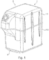
- Figure 1 shows a perspective view of a reducing agent tank T for a reducing agent, in particular a urea tank for a preferably aqueous urea solution, for. B. AdBlue.
- Figure 2 shows another perspective view of the reducing agent tank T of Figure 1 with an illustrative omission, so that the reducing agent tank T can be viewed for illustration purposes.
- the reducing agent tank T comprises a housing 1 comprising two housing sections 1.1 and 1.2, which are mounted to one another, for receiving the reducing agent, a delivery module 2 for delivering the reducing agent, and a tank segment 3 arranged under the housing 1.
- the reducing agent tank T is used for mounting on a motor vehicle, preferably a commercial vehicle , especially a truck or an omnibus.
- the tank segment 3 is provided with an integrated fluid channel 3.1 for guiding a fluid for heating the reducing agent, so that the tank segment 3 itself forms the fluid channel 3.1.
- the tank segment 3 and the fluid channel 3.1 are thus formed by one and the same molded part, preferably an injection molded part.
- the tank segment 3 is produced in such a way that the fluid channel 3.1 is integrated, in particular is formed with, for. B. is molded or molded.
- the tank segment 3 comprises a flat, suitably hood-shaped wall 3.3, on the inside of which the fluid channel 3.1 is formed.
- the sheet-like wall 3.3 expediently forms a lower end cover for the housing 1.
- the tank segment 3 forms a boundary structure 3.2 for the fluid channel 3.1.
- the delimiting structure 3.2 delimits the fluid channel 3.1 along its longitudinal extent L.
- the delimiting structure 3.2 comprises two essentially parallel wall elements 3.2 and an inside part of the sheet-like wall 3.3.
- the two wall elements 3.2 laterally limit the fluid channel 3.1.
- the sheet-like wall 3.3 delimits the fluid channel 3.1 downwards.
- the tank segment 3 in particular the delimitation structure 3.2 and 3.3, leaves the fluid channel 3.1 open on one side, namely in Figure 2 towards the top.
- the open side so in Figure 2 the top, and thus the fluid channel 3.1, is closed in the assembled state of the reducing agent tank T by an adjacent tank element, namely in Figure 2 through a base segment, expediently a base plate, of the housing 1.
- the tank segment 3 further comprises a receiving opening for the delivery module 2 for delivering the reducing agent, so that the delivery module 2 is expediently integrated into the tank segment 3.
- the fluid channel 3.1 extends at least in sections essentially in a circular arc and in a meandering shape around the receiving opening and thus around the delivery module 2.
- the tank segment 3 comprises a fluid channel inlet 3.4 and a fluid channel outlet 3.5.
- the fluid channel 3.1 is used for connection to a line for cooling fluid for cooling an internal combustion engine (for example an internal combustion engine, gasoline engine, etc.) of a motor vehicle Figures 1 and 2 it can be seen that the tank segment 3 serves as a floor cover and at the same time as a floor heater for the housing 1 and thus the reducing agent.
- an internal combustion engine for example an internal combustion engine, gasoline engine, etc.
- FIGS. 3 and 4 show different perspective views of a tank segment 3 according to an embodiment of the invention, which is identical to the tank segment 3 of FIG Figures 1 and 2 is executed.
- the tank segment 3 is provided with an integrated fluid channel 3.1 and the tank segment 3 including the fluid channel 3.1 is formed by one and the same molded part.
- the fluid channel 3.1 is therefore expediently an integral part of the tank segment 3.
- the fluid channel 3.1 is formed on the inside of the sheet-like wall 3.3 and is in the assembled state of the reducing agent tank 3 along its longitudinal extension L below by part of the sheet-like wall 3.3, laterally by the two essentially parallel wall elements 3.2 and above by a bottom segment of the housing 1 limited.
- the fluid channel 3.1 runs in an arcuate and meandering manner around the receiving opening for the delivery module 2.
- the tank segment 3 further comprises a plurality of stiffening ribs, in particular for stiffening the sheet-like wall 3.3.
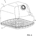
- Figure 5 shows an exploded view of a reducing agent tank T according to another embodiment of the invention while Figure 6 an associated perspective view of the reducing agent tank T shows.
- the design of the tank element 4 represents a special feature.
- the preferably plate-shaped tank element 4 is arranged between the housing 1 and the tank segment 3, serves to close the fluid channel 3.1 towards the top and serves to separate and at the same time contact the reducing agent in the housing 1 and the fluid in the tank segment 3, in particular in the fluid channel 3.1.
- the tank element 4 is formed from plastic material, which is additized with at least one filler material (e.g. filler, additive and / or additive), so that the filler material is expediently embedded in the plastic material, in particular is admixed with the same.
- the filler material serves to increase the thermal conductivity of the plastic material, so that the heat of the fluid from the fluid channel 3.1 can be transferred more effectively to the reducing agent in the housing 1.
- the addition of the filler material to the plastic material is expediently carried out during the manufacturing process of the tank element 4.
- the thermal conductivity of the plastic material of the tank element 4 can be increased by proportionally admixing / additizing the filler material, so that the heat output of the tank segment 3 can expediently be increased.
- the plastic material and / or its filler material must be urea-resistant.
- the filler material may also not be urea-resistant if it is appropriately incorporated into the plastic. In this case, the filler material must be manufactured by appropriate manufacturing z. B. completely enclosed by plastic material so as not to have any contact with the urea.
- the filler material can e.g. B. include boron nitride, which on the one hand leads to an improvement in the thermal conductivity of the plastic material and on the other hand is urea-resistant.
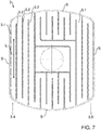
- Figure 7 shows a top view of the tank segment 3 of FIG Figures 5 and 6
- Figure 8 shows an associated perspective view of the tank segment 3.
- the fluid channel 3.1 is delimited along its longitudinal extent L by means of a delimiting structure 3.2 formed by the tank segment 3.
- the delimiting structure 3.2 includes the side outer walls S of the tank segment 3.
- the delimiting structure 3.2 does not include, as in the embodiment of FIG Figures 1 to 4 only one pair of wall elements, the wall elements of which extend continuously over the tank segment 3, but a plurality of pairs of wall elements, the wall elements of which overlap in sections, extend in opposite directions and expediently discontinuously.
- the wall element pairs produce a change in fluid channel direction at their longitudinal ends by essentially 180 °.
Landscapes
- Chemical & Material Sciences (AREA)
- Engineering & Computer Science (AREA)
- Chemical Kinetics & Catalysis (AREA)
- Health & Medical Sciences (AREA)
- Toxicology (AREA)
- Combustion & Propulsion (AREA)
- Mechanical Engineering (AREA)
- General Engineering & Computer Science (AREA)
- Exhaust Gas After Treatment (AREA)
Claims (22)
- Réservoir d'agent réducteur (T) pour un agent réducteur et de préférence à monter sur un véhicule automobile, avec une enceinte (1) destinée à contenir l'agent réducteur, un segment de réservoir (3) et de préférence un module de transport (2) pour le transport de l'agent réducteur, et un élément de réservoir (4) en matière plastique, caractérisé en ce qu'à la matière plastique est ajouté au moins un matériau supplémentaire pour accroître la conductibilité thermique.
- Réservoir d'agent réducteur (T) selon la revendication 1, caractérisé en ce qu'une seule et même pièce moulée forme le segment de réservoir (3) et le canal de fluide (3.1) .
- Réservoir d'agent réducteur (T) selon une des revendications précédentes, caractérisé en ce que le segment de réservoir (3) et/ou la pièce moulée sont une pièce moulée par injection.
- Réservoir d'agent réducteur (T) selon une des revendications précédentes, caractérisé en ce que le canal de fluide (3.1) est formé sur un côté intérieur du segment de réservoir (3).
- Réservoir d'agent réducteur (T) selon une des revendications précédentes, caractérisé en ce que le segment de réservoir (3) présente le module de transport (2) et/ou présente une ouverture de réception pour le module de transport (2).
- Réservoir d'agent réducteur (T) selon une des revendications précédentes, caractérisé en ce qu'au moins un canal de fluide (3.1) s'étend au moins en partie en forme d'arc autour de l'ouverture de réception pour le module de transport (2) et/ou au moins en partie en ligne droite.
- Réservoir d'agent réducteur (T) selon une des revendications précédentes, caractérisé en ce que le segment de réservoir (3) comprend une paroi en forme de hotte et/ou de plaque (3.3) et la paroi (3.3) forme un recouvrement d'extrémité de préférence inférieur pour l'enceinte (1).
- Réservoir d'agent réducteur (T) selon une des revendications précédentes, caractérisé en ce que le canal de fluide (3.1) est limité le long de son extension longitudinale (L) au moyen d'une structure de limitation (3.2) formée par le segment de réservoir (3).
- Réservoir d'agent réducteur (T) selon une des revendications précédentes, caractérisé en ce que le segment de réservoir (3) et/ou la structure de limitation (3.2) laisse(nt) le canal de fluide (3.1) ouvert vers un côté et le côté et dès lors le canal de fluide (3.1) est fermé par un élément de réservoir voisin (4).
- Réservoir d'agent réducteur (T) selon une des revendications précédentes, caractérisé en ce que le segment de réservoir (3) et/ou la structure de limitation (3.2) laisse(nt) le canal de fluide (3.1) ouvert vers le côté supérieur et le côté supérieur est fermé par un élément de réservoir (4) superposé, en particulier par un segment de fond de l'enceinte (1).
- Réservoir d'agent réducteur (T) selon une des revendications précédentes, caractérisé en ce que le segment de réservoir (3) est disposé en dessous d'un élément de réservoir (4), en particulier d'un segment de fond de l'enceinte (1) et/ou fait office de chauffage de fond pour l'enceinte (1) et dès lors pour l'agent réducteur.
- Réservoir d'agent réducteur (T) selon une des revendications précédentes, caractérisé en ce que le canal de fluide (3.1) peut être raccordé à un circuit de refroidissement d'un moteur à combustion interne du véhicule à moteur.
- Réservoir d'agent réducteur (T) selon une des revendications précédentes, caractérisé en ce que le canal de fluide (3.1) est limité au moyen d'une structure de limitation (3.2) formée par le segment de réservoir (3) et la structure de limitation (3.2) comprend une ou plusieurs parois extérieures latérales du segment de réservoir (3).
- Réservoir d'agent réducteur (T) selon une des revendications précédentes, caractérisé en ce que le canal de fluide (3.1) s'étend au moins en partie en forme de méandres, en forme de labyrinthe et/ou en forme d'hélice.
- Réservoir d'agent réducteur (T) selon une des revendications précédentes, caractérisé en ce que le canal de fluide (3.1) est limité au moyen d'une structure de limitation (3.2) formée par le segment de réservoir (3) et la structure de limitation (3.2) comprend une paire d'éléments de paroi, dont les éléments de paroi s'étendent sous forme continue sur le segment de réservoir (3), ou comprend une pluralité de paires d'éléments de paroi, dont les éléments de paroi se chevauchent en partie et s'étendent de préférence en sens inverse.
- Réservoir d'agent réducteur (T) selon une des revendications précédentes, caractérisé en ce que l'élément de réservoir (4) en matière plastique est disposé entre l'enceinte (1) et le segment de réservoir (3) .
- Réservoir d'agent réducteur (T) selon la revendication 16, caractérisé en ce que la matière plastique et/ou le matériau supplémentaire est résistant à l'urée.
- Réservoir d'agent réducteur (T) selon la revendication 16 ou 17, caractérisé en ce que l'élément de réservoir (4) est réalisé pour séparer et/ou mettre en contact l'agent réducteur dans l'enceinte (1) et le fluide dans le segment de réservoir (3).
- Réservoir d'agent réducteur (T) selon une des revendications 16 à 18, caractérisé en ce que le matériau supplémentaire comprend du nitrure de bore.
- Réservoir d'agent réducteur (T) selon une des revendications 16 à 19, caractérisé en ce que le matériau supplémentaire est incorporé dans la matière plastique, afin d'être isolé de l'agent réducteur, et notamment de ne pas venir ainsi en contact avec l'agent réducteur.
- Réservoir d'agent réducteur (T) selon une des revendications précédentes, caractérisé en ce que le réservoir d'agent réducteur (T) présente un dispositif de chauffage électrique pour chauffer l'agent réducteur dans l'enceinte (1).
- Véhicule à moteur, en particulier véhicule utilitaire, muni d'un réservoir d'agent réducteur (T) selon une des revendications 1 à 21.
Applications Claiming Priority (3)
| Application Number | Priority Date | Filing Date | Title |
|---|---|---|---|
| DE102015008351.1A DE102015008351A1 (de) | 2015-06-27 | 2015-06-27 | Reduktionsmitteltank mit integriertem Fluidkanal zum Führen eines Heizfluides |
| DE102015012625.3A DE102015012625A1 (de) | 2015-09-26 | 2015-09-26 | Reduktionsmitteltank mit integriertem Fluidkanal zum Führen eines Heizfluides |
| EP16001351.2A EP3109425B1 (fr) | 2015-06-27 | 2016-06-15 | Réservoir de moyen de réduction avec canal de fluide intégré pour la conduite d'un fluide chaud |
Related Parent Applications (2)
| Application Number | Title | Priority Date | Filing Date |
|---|---|---|---|
| EP16001351.2A Division EP3109425B1 (fr) | 2015-06-27 | 2016-06-15 | Réservoir de moyen de réduction avec canal de fluide intégré pour la conduite d'un fluide chaud |
| EP16001351.2A Division-Into EP3109425B1 (fr) | 2015-06-27 | 2016-06-15 | Réservoir de moyen de réduction avec canal de fluide intégré pour la conduite d'un fluide chaud |
Publications (2)
| Publication Number | Publication Date |
|---|---|
| EP3399167A1 EP3399167A1 (fr) | 2018-11-07 |
| EP3399167B1 true EP3399167B1 (fr) | 2020-01-01 |
Family
ID=56235523
Family Applications (2)
| Application Number | Title | Priority Date | Filing Date |
|---|---|---|---|
| EP18179743.2A Active EP3399167B1 (fr) | 2015-06-27 | 2016-06-15 | Réservoir de moyen de réduction pourvu de canal de fluide intégré permettant de conduire un fluide chaud |
| EP16001351.2A Active EP3109425B1 (fr) | 2015-06-27 | 2016-06-15 | Réservoir de moyen de réduction avec canal de fluide intégré pour la conduite d'un fluide chaud |
Family Applications After (1)
| Application Number | Title | Priority Date | Filing Date |
|---|---|---|---|
| EP16001351.2A Active EP3109425B1 (fr) | 2015-06-27 | 2016-06-15 | Réservoir de moyen de réduction avec canal de fluide intégré pour la conduite d'un fluide chaud |
Country Status (4)
| Country | Link |
|---|---|
| EP (2) | EP3399167B1 (fr) |
| CN (2) | CN106285860A (fr) |
| BR (2) | BR122020020091B1 (fr) |
| RU (2) | RU2769211C2 (fr) |
Families Citing this family (2)
| Publication number | Priority date | Publication date | Assignee | Title |
|---|---|---|---|---|
| IT201800020962A1 (it) * | 2018-12-21 | 2020-06-21 | Officine Metallurgiche G Cornaglia Spa | Serbatoio veicolare per una soluzione di urea e suo metodo di realizzazione |
| CN111577418A (zh) * | 2020-05-28 | 2020-08-25 | 中国船舶工业集团公司第七0八研究所 | 一种fsru上超临界三级级联朗肯循环发电系统 |
Family Cites Families (19)
| Publication number | Priority date | Publication date | Assignee | Title |
|---|---|---|---|---|
| CN86106962A (zh) * | 1986-11-01 | 1988-05-11 | 菲利浦光灯制造公司 | 家用电冰箱铝合金汽化器及其制造方法 |
| DE10231624A1 (de) * | 2002-07-12 | 2004-01-29 | Robert Bosch Gmbh | Piezoelektrisches Bauelement |
| DE20314557U1 (de) * | 2003-09-19 | 2003-11-20 | Sauermann Franz | Behälter für aggressive Flüssigkeiten mit Heiz- und/oder Kühlmöglichkeit |
| DE202005019499U1 (de) * | 2005-12-14 | 2006-02-09 | Man Nutzfahrzeuge Ag | Beheizung eines Tanks für Harnstoffwasserlösung |
| KR100706653B1 (ko) * | 2006-12-27 | 2007-04-13 | 제일모직주식회사 | 열전도성 수지 조성물 및 플라스틱 성형품 |
| CN101261094B (zh) * | 2008-04-24 | 2011-09-07 | 丁宏广 | 一种板式热交换器的用途及外壳包含至少一个该板式热交换器的容器 |
| DE102009000094A1 (de) * | 2009-01-09 | 2010-07-15 | Robert Bosch Gmbh | Tank zur Aufnahme einer wässrigen Lösung |
| DE102010004614A1 (de) * | 2010-01-13 | 2011-07-14 | Emitec Gesellschaft für Emissionstechnologie mbH, 53797 | Tankanordnung und Dosiersystem für ein Reduktionsmittel |
| DE102010005056A1 (de) * | 2010-01-20 | 2011-07-21 | Emitec Gesellschaft für Emissionstechnologie mbH, 53797 | Behälter für eine Flüssigkeit, insbesondere ein Reduktionsmittel |
| DE102010029269A1 (de) * | 2010-05-25 | 2011-12-01 | Robert Bosch Gmbh | Beheizbarer Tankbehälter |
| US20130000743A1 (en) * | 2011-06-29 | 2013-01-03 | Ti Group Automotive Systems, L.L.C. | Scr fluid distribution and circulation system |
| CN102979602B (zh) * | 2011-07-18 | 2015-05-06 | 苏州派格丽减排系统有限公司 | Scr系统还原剂计量与储存装置的液体加热系统 |
| DE102011108213A1 (de) | 2011-07-21 | 2013-01-24 | Audi Ag | Beheizbarer Reduktionsmitteltank |
| DE102012020040B4 (de) * | 2012-10-12 | 2015-04-16 | Kautex Textron Gmbh & Co. Kg | Einrichtung zur Bevorratung und Förderung eines wässrigen Additivs |
| EP2733321B1 (fr) * | 2012-08-28 | 2017-11-08 | Yapp Automotive Parts Co., Ltd. | Procédé de fabrication d'un réservoir d'urée pour automobile |
| DE102012109675A1 (de) * | 2012-10-11 | 2014-04-30 | Emitec Denmark A/S | Vorrichtung zur Bereitstellung eines flüssigen Additivs |
| CN202954873U (zh) * | 2012-11-16 | 2013-05-29 | 平凡科技有限公司 | 柴油发动机尾气后处理scr系统用尿素箱 |
| CN203106868U (zh) * | 2012-12-25 | 2013-08-07 | 奥特朗电器(广州)有限公司 | 余热回收式洗漱盆 |
| DE102014200711A1 (de) * | 2014-01-16 | 2015-07-16 | Robert Bosch Gmbh | Vorrichtung und Verfahren zum Beheizen eines Fluids |
-
2016
- 2016-06-15 EP EP18179743.2A patent/EP3399167B1/fr active Active
- 2016-06-15 EP EP16001351.2A patent/EP3109425B1/fr active Active
- 2016-06-24 RU RU2020107305A patent/RU2769211C2/ru active
- 2016-06-24 RU RU2016125220A patent/RU2721065C2/ru active
- 2016-06-27 CN CN201610475356.XA patent/CN106285860A/zh active Pending
- 2016-06-27 CN CN201911394656.5A patent/CN111075542A/zh active Pending
- 2016-06-27 BR BR122020020091-0A patent/BR122020020091B1/pt active IP Right Grant
- 2016-06-27 BR BR102016015053-1A patent/BR102016015053B1/pt active IP Right Grant
Non-Patent Citations (1)
| Title |
|---|
| None * |
Also Published As
| Publication number | Publication date |
|---|---|
| BR122020020091B1 (pt) | 2023-01-31 |
| CN106285860A (zh) | 2017-01-04 |
| RU2769211C2 (ru) | 2022-03-29 |
| BR102016015053A2 (pt) | 2017-07-25 |
| CN111075542A (zh) | 2020-04-28 |
| EP3109425A1 (fr) | 2016-12-28 |
| EP3399167A1 (fr) | 2018-11-07 |
| RU2020107305A (ru) | 2020-03-26 |
| RU2020107305A3 (fr) | 2022-01-26 |
| EP3109425B1 (fr) | 2018-08-15 |
| RU2721065C2 (ru) | 2020-05-15 |
| BR102016015053B1 (pt) | 2023-02-14 |
| RU2016125220A (ru) | 2017-12-26 |
Similar Documents
| Publication | Publication Date | Title |
|---|---|---|
| EP1893852B1 (fr) | Systeme d'alimentation en agent de reduction destine a un catalyseur d'epuration des gaz d'echappement et dispositif de chauffage correspondant | |
| EP2010768B1 (fr) | Système de conduites flexibles chauffable d'installations de retraitement des gaz d'échappement de moteurs à combustion interne | |
| EP2577012B1 (fr) | Dispositif chauffant de prise de fluide | |
| DE102005037201A1 (de) | Heizsystem | |
| DE102007050272A1 (de) | Tank zur Bevorratung eines Reduktionsmittels | |
| KR20150054872A (ko) | 작동 유체용 플라스틱 탱크 | |
| EP3152422A1 (fr) | Dispositif de fourniture d'un additif liquide | |
| EP3399167B1 (fr) | Réservoir de moyen de réduction pourvu de canal de fluide intégré permettant de conduire un fluide chaud | |
| DE112013000149T5 (de) | Arbeitsfahrzeug | |
| EP1770251B1 (fr) | Module de tuyauterie souple chauffable pour dispositifs de traitement de gaz d'échappement de moteurs à combustion interne | |
| DE102014108074A1 (de) | Heizmodul und Tanksystem | |
| DE202005019499U1 (de) | Beheizung eines Tanks für Harnstoffwasserlösung | |
| EP1741888A1 (fr) | Réservoir d'un véhicule automobile | |
| EP1257448B1 (fr) | Dispositif de rechauffement d'un liquide dans un systeme de conduite | |
| WO2010046152A1 (fr) | Système de dosage pour un fluide liquide, en particulier pour une solution d'eau et d'urée | |
| DE102011053053A1 (de) | Schlauchleitung | |
| EP3109424B1 (fr) | Réservoir de moyen de réduction avec canal de fluide intégré pour la conduite d'un fluide chaud | |
| EP2122153B1 (fr) | Unité d'alimentation | |
| DE102015012625A1 (de) | Reduktionsmitteltank mit integriertem Fluidkanal zum Führen eines Heizfluides | |
| DE102016203558A1 (de) | Wärmetauscher zur wenigstens teilweisen Anordnung in einem Betriebsflüssigkeitstank und Wärmetauscherkörper für einen solchen Wärmetauscher | |
| EP2748024A1 (fr) | Ensemble réservoir et dispositif d'épuration des gaz d'échappement | |
| DE102005039565B4 (de) | Abgasnachbehandlungsvorrichtung sowie Verfahren zum Betreiben einer Abgasnachbehandlungsvorrichtung | |
| WO2018121908A1 (fr) | Ensemble réservoir pour véhicule | |
| DE102015204353A1 (de) | Behälter für ein flüssiges Betriebsmittel eines Kraftfahrzeuges und Kraftfahrzeug mit einem solchen Behälter | |
| DE102014010836B4 (de) | Fluidrohr einer Fluidleitung eines Kraftfahrzeugs, Kraftfahrzeug und Brennkraftmaschine mit wenigstens einem Fluidrohr |
Legal Events
| Date | Code | Title | Description |
|---|---|---|---|
| PUAI | Public reference made under article 153(3) epc to a published international application that has entered the european phase |
Free format text: ORIGINAL CODE: 0009012 |
|
| STAA | Information on the status of an ep patent application or granted ep patent |
Free format text: STATUS: THE APPLICATION HAS BEEN PUBLISHED |
|
| AC | Divisional application: reference to earlier application |
Ref document number: 3109425 Country of ref document: EP Kind code of ref document: P |
|
| AK | Designated contracting states |
Kind code of ref document: A1 Designated state(s): AL AT BE BG CH CY CZ DE DK EE ES FI FR GB GR HR HU IE IS IT LI LT LU LV MC MK MT NL NO PL PT RO RS SE SI SK SM TR |
|
| STAA | Information on the status of an ep patent application or granted ep patent |
Free format text: STATUS: REQUEST FOR EXAMINATION WAS MADE |
|
| 17P | Request for examination filed |
Effective date: 20190429 |
|
| RBV | Designated contracting states (corrected) |
Designated state(s): AL AT BE BG CH CY CZ DE DK EE ES FI FR GB GR HR HU IE IS IT LI LT LU LV MC MK MT NL NO PL PT RO RS SE SI SK SM TR |
|
| RAP1 | Party data changed (applicant data changed or rights of an application transferred) |
Owner name: MAN TRUCK & BUS SE |
|
| GRAP | Despatch of communication of intention to grant a patent |
Free format text: ORIGINAL CODE: EPIDOSNIGR1 |
|
| STAA | Information on the status of an ep patent application or granted ep patent |
Free format text: STATUS: GRANT OF PATENT IS INTENDED |
|
| INTG | Intention to grant announced |
Effective date: 20190920 |
|
| GRAS | Grant fee paid |
Free format text: ORIGINAL CODE: EPIDOSNIGR3 |
|
| GRAA | (expected) grant |
Free format text: ORIGINAL CODE: 0009210 |
|
| STAA | Information on the status of an ep patent application or granted ep patent |
Free format text: STATUS: THE PATENT HAS BEEN GRANTED |
|
| AC | Divisional application: reference to earlier application |
Ref document number: 3109425 Country of ref document: EP Kind code of ref document: P |
|
| AK | Designated contracting states |
Kind code of ref document: B1 Designated state(s): AL AT BE BG CH CY CZ DE DK EE ES FI FR GB GR HR HU IE IS IT LI LT LU LV MC MK MT NL NO PL PT RO RS SE SI SK SM TR |
|
| REG | Reference to a national code |
Ref country code: GB Ref legal event code: FG4D Free format text: NOT ENGLISH |
|
| REG | Reference to a national code |
Ref country code: CH Ref legal event code: EP Ref country code: AT Ref legal event code: REF Ref document number: 1220048 Country of ref document: AT Kind code of ref document: T Effective date: 20200115 |
|
| REG | Reference to a national code |
Ref country code: IE Ref legal event code: FG4D Free format text: LANGUAGE OF EP DOCUMENT: GERMAN |
|
| REG | Reference to a national code |
Ref country code: DE Ref legal event code: R096 Ref document number: 502016008293 Country of ref document: DE |
|
| REG | Reference to a national code |
Ref country code: NL Ref legal event code: FP |
|
| REG | Reference to a national code |
Ref country code: SE Ref legal event code: TRGR |
|
| REG | Reference to a national code |
Ref country code: LT Ref legal event code: MG4D |
|
| PG25 | Lapsed in a contracting state [announced via postgrant information from national office to epo] |
Ref country code: RS Free format text: LAPSE BECAUSE OF FAILURE TO SUBMIT A TRANSLATION OF THE DESCRIPTION OR TO PAY THE FEE WITHIN THE PRESCRIBED TIME-LIMIT Effective date: 20200101 Ref country code: NO Free format text: LAPSE BECAUSE OF FAILURE TO SUBMIT A TRANSLATION OF THE DESCRIPTION OR TO PAY THE FEE WITHIN THE PRESCRIBED TIME-LIMIT Effective date: 20200401 Ref country code: FI Free format text: LAPSE BECAUSE OF FAILURE TO SUBMIT A TRANSLATION OF THE DESCRIPTION OR TO PAY THE FEE WITHIN THE PRESCRIBED TIME-LIMIT Effective date: 20200101 Ref country code: CZ Free format text: LAPSE BECAUSE OF FAILURE TO SUBMIT A TRANSLATION OF THE DESCRIPTION OR TO PAY THE FEE WITHIN THE PRESCRIBED TIME-LIMIT Effective date: 20200101 Ref country code: PT Free format text: LAPSE BECAUSE OF FAILURE TO SUBMIT A TRANSLATION OF THE DESCRIPTION OR TO PAY THE FEE WITHIN THE PRESCRIBED TIME-LIMIT Effective date: 20200527 Ref country code: LT Free format text: LAPSE BECAUSE OF FAILURE TO SUBMIT A TRANSLATION OF THE DESCRIPTION OR TO PAY THE FEE WITHIN THE PRESCRIBED TIME-LIMIT Effective date: 20200101 |
|
| PG25 | Lapsed in a contracting state [announced via postgrant information from national office to epo] |
Ref country code: SE Free format text: LAPSE BECAUSE OF FAILURE TO SUBMIT A TRANSLATION OF THE DESCRIPTION OR TO PAY THE FEE WITHIN THE PRESCRIBED TIME-LIMIT Effective date: 20200101 Ref country code: LV Free format text: LAPSE BECAUSE OF FAILURE TO SUBMIT A TRANSLATION OF THE DESCRIPTION OR TO PAY THE FEE WITHIN THE PRESCRIBED TIME-LIMIT Effective date: 20200101 Ref country code: BG Free format text: LAPSE BECAUSE OF FAILURE TO SUBMIT A TRANSLATION OF THE DESCRIPTION OR TO PAY THE FEE WITHIN THE PRESCRIBED TIME-LIMIT Effective date: 20200401 Ref country code: IS Free format text: LAPSE BECAUSE OF FAILURE TO SUBMIT A TRANSLATION OF THE DESCRIPTION OR TO PAY THE FEE WITHIN THE PRESCRIBED TIME-LIMIT Effective date: 20200501 Ref country code: GR Free format text: LAPSE BECAUSE OF FAILURE TO SUBMIT A TRANSLATION OF THE DESCRIPTION OR TO PAY THE FEE WITHIN THE PRESCRIBED TIME-LIMIT Effective date: 20200402 Ref country code: HR Free format text: LAPSE BECAUSE OF FAILURE TO SUBMIT A TRANSLATION OF THE DESCRIPTION OR TO PAY THE FEE WITHIN THE PRESCRIBED TIME-LIMIT Effective date: 20200101 |
|
| REG | Reference to a national code |
Ref country code: DE Ref legal event code: R097 Ref document number: 502016008293 Country of ref document: DE |
|
| PG25 | Lapsed in a contracting state [announced via postgrant information from national office to epo] |
Ref country code: DK Free format text: LAPSE BECAUSE OF FAILURE TO SUBMIT A TRANSLATION OF THE DESCRIPTION OR TO PAY THE FEE WITHIN THE PRESCRIBED TIME-LIMIT Effective date: 20200101 Ref country code: SK Free format text: LAPSE BECAUSE OF FAILURE TO SUBMIT A TRANSLATION OF THE DESCRIPTION OR TO PAY THE FEE WITHIN THE PRESCRIBED TIME-LIMIT Effective date: 20200101 Ref country code: ES Free format text: LAPSE BECAUSE OF FAILURE TO SUBMIT A TRANSLATION OF THE DESCRIPTION OR TO PAY THE FEE WITHIN THE PRESCRIBED TIME-LIMIT Effective date: 20200101 Ref country code: RO Free format text: LAPSE BECAUSE OF FAILURE TO SUBMIT A TRANSLATION OF THE DESCRIPTION OR TO PAY THE FEE WITHIN THE PRESCRIBED TIME-LIMIT Effective date: 20200101 Ref country code: EE Free format text: LAPSE BECAUSE OF FAILURE TO SUBMIT A TRANSLATION OF THE DESCRIPTION OR TO PAY THE FEE WITHIN THE PRESCRIBED TIME-LIMIT Effective date: 20200101 Ref country code: SM Free format text: LAPSE BECAUSE OF FAILURE TO SUBMIT A TRANSLATION OF THE DESCRIPTION OR TO PAY THE FEE WITHIN THE PRESCRIBED TIME-LIMIT Effective date: 20200101 |
|
| PLBE | No opposition filed within time limit |
Free format text: ORIGINAL CODE: 0009261 |
|
| STAA | Information on the status of an ep patent application or granted ep patent |
Free format text: STATUS: NO OPPOSITION FILED WITHIN TIME LIMIT |
|
| 26N | No opposition filed |
Effective date: 20201002 |
|
| PG25 | Lapsed in a contracting state [announced via postgrant information from national office to epo] |
Ref country code: MC Free format text: LAPSE BECAUSE OF FAILURE TO SUBMIT A TRANSLATION OF THE DESCRIPTION OR TO PAY THE FEE WITHIN THE PRESCRIBED TIME-LIMIT Effective date: 20200101 |
|
| REG | Reference to a national code |
Ref country code: CH Ref legal event code: PL |
|
| PG25 | Lapsed in a contracting state [announced via postgrant information from national office to epo] |
Ref country code: SI Free format text: LAPSE BECAUSE OF FAILURE TO SUBMIT A TRANSLATION OF THE DESCRIPTION OR TO PAY THE FEE WITHIN THE PRESCRIBED TIME-LIMIT Effective date: 20200101 Ref country code: PL Free format text: LAPSE BECAUSE OF FAILURE TO SUBMIT A TRANSLATION OF THE DESCRIPTION OR TO PAY THE FEE WITHIN THE PRESCRIBED TIME-LIMIT Effective date: 20200101 |
|
| GBPC | Gb: european patent ceased through non-payment of renewal fee |
Effective date: 20200615 |
|
| PG25 | Lapsed in a contracting state [announced via postgrant information from national office to epo] |
Ref country code: LU Free format text: LAPSE BECAUSE OF NON-PAYMENT OF DUE FEES Effective date: 20200615 |
|
| REG | Reference to a national code |
Ref country code: BE Ref legal event code: MM Effective date: 20200630 |
|
| PG25 | Lapsed in a contracting state [announced via postgrant information from national office to epo] |
Ref country code: IE Free format text: LAPSE BECAUSE OF NON-PAYMENT OF DUE FEES Effective date: 20200615 Ref country code: GB Free format text: LAPSE BECAUSE OF NON-PAYMENT OF DUE FEES Effective date: 20200615 Ref country code: LI Free format text: LAPSE BECAUSE OF NON-PAYMENT OF DUE FEES Effective date: 20200630 Ref country code: CH Free format text: LAPSE BECAUSE OF NON-PAYMENT OF DUE FEES Effective date: 20200630 |
|
| PG25 | Lapsed in a contracting state [announced via postgrant information from national office to epo] |
Ref country code: BE Free format text: LAPSE BECAUSE OF NON-PAYMENT OF DUE FEES Effective date: 20200630 |
|
| PG25 | Lapsed in a contracting state [announced via postgrant information from national office to epo] |
Ref country code: TR Free format text: LAPSE BECAUSE OF FAILURE TO SUBMIT A TRANSLATION OF THE DESCRIPTION OR TO PAY THE FEE WITHIN THE PRESCRIBED TIME-LIMIT Effective date: 20200101 Ref country code: MT Free format text: LAPSE BECAUSE OF FAILURE TO SUBMIT A TRANSLATION OF THE DESCRIPTION OR TO PAY THE FEE WITHIN THE PRESCRIBED TIME-LIMIT Effective date: 20200101 Ref country code: CY Free format text: LAPSE BECAUSE OF FAILURE TO SUBMIT A TRANSLATION OF THE DESCRIPTION OR TO PAY THE FEE WITHIN THE PRESCRIBED TIME-LIMIT Effective date: 20200101 |
|
| PG25 | Lapsed in a contracting state [announced via postgrant information from national office to epo] |
Ref country code: MK Free format text: LAPSE BECAUSE OF FAILURE TO SUBMIT A TRANSLATION OF THE DESCRIPTION OR TO PAY THE FEE WITHIN THE PRESCRIBED TIME-LIMIT Effective date: 20200101 Ref country code: AL Free format text: LAPSE BECAUSE OF FAILURE TO SUBMIT A TRANSLATION OF THE DESCRIPTION OR TO PAY THE FEE WITHIN THE PRESCRIBED TIME-LIMIT Effective date: 20200101 |
|
| REG | Reference to a national code |
Ref country code: AT Ref legal event code: MM01 Ref document number: 1220048 Country of ref document: AT Kind code of ref document: T Effective date: 20210615 |
|
| PG25 | Lapsed in a contracting state [announced via postgrant information from national office to epo] |
Ref country code: AT Free format text: LAPSE BECAUSE OF NON-PAYMENT OF DUE FEES Effective date: 20210615 |
|
| PGFP | Annual fee paid to national office [announced via postgrant information from national office to epo] |
Ref country code: SE Payment date: 20230317 Year of fee payment: 8 |
|
| PGFP | Annual fee paid to national office [announced via postgrant information from national office to epo] |
Ref country code: NL Payment date: 20230626 Year of fee payment: 8 Ref country code: FR Payment date: 20230622 Year of fee payment: 8 Ref country code: DE Payment date: 20230627 Year of fee payment: 8 |
|
| PGFP | Annual fee paid to national office [announced via postgrant information from national office to epo] |
Ref country code: IT Payment date: 20230620 Year of fee payment: 8 |