EP3397137B1 - Dispositif de suivi oculaire basé sur une imagerie rétinienne par l'intermédiaire d'un guide d'ondes optique - Google Patents
Dispositif de suivi oculaire basé sur une imagerie rétinienne par l'intermédiaire d'un guide d'ondes optique Download PDFInfo
- Publication number
- EP3397137B1 EP3397137B1 EP17885744.7A EP17885744A EP3397137B1 EP 3397137 B1 EP3397137 B1 EP 3397137B1 EP 17885744 A EP17885744 A EP 17885744A EP 3397137 B1 EP3397137 B1 EP 3397137B1
- Authority
- EP
- European Patent Office
- Prior art keywords
- eye
- light
- illumination
- loe
- processing system
- Prior art date
- Legal status (The legal status is an assumption and is not a legal conclusion. Google has not performed a legal analysis and makes no representation as to the accuracy of the status listed.)
- Active
Links
- 230000003287 optical effect Effects 0.000 title claims description 97
- 238000003384 imaging method Methods 0.000 title description 15
- 230000002207 retinal effect Effects 0.000 title description 9
- 210000001508 eye Anatomy 0.000 claims description 123
- 238000005286 illumination Methods 0.000 claims description 112
- 238000012545 processing Methods 0.000 claims description 45
- 210000001525 retina Anatomy 0.000 claims description 45
- 238000000034 method Methods 0.000 claims description 25
- 210000000887 face Anatomy 0.000 claims description 24
- 230000008569 process Effects 0.000 claims description 19
- 230000001902 propagating effect Effects 0.000 claims description 11
- 239000012780 transparent material Substances 0.000 claims description 9
- 210000004204 blood vessel Anatomy 0.000 claims description 5
- 210000003128 head Anatomy 0.000 claims description 4
- 230000003595 spectral effect Effects 0.000 claims description 4
- 230000026676 system process Effects 0.000 claims description 4
- 230000008447 perception Effects 0.000 claims description 3
- 238000001228 spectrum Methods 0.000 claims description 3
- 230000005670 electromagnetic radiation Effects 0.000 claims description 2
- 210000001747 pupil Anatomy 0.000 description 9
- 239000000758 substrate Substances 0.000 description 9
- 230000008878 coupling Effects 0.000 description 8
- 238000010168 coupling process Methods 0.000 description 8
- 238000005859 coupling reaction Methods 0.000 description 8
- 230000005855 radiation Effects 0.000 description 8
- 230000002441 reversible effect Effects 0.000 description 8
- 238000013459 approach Methods 0.000 description 7
- 238000001514 detection method Methods 0.000 description 7
- 230000006870 function Effects 0.000 description 7
- 230000010354 integration Effects 0.000 description 7
- 230000033001 locomotion Effects 0.000 description 6
- 238000002310 reflectometry Methods 0.000 description 6
- 230000005540 biological transmission Effects 0.000 description 5
- 239000011521 glass Substances 0.000 description 5
- 238000004364 calculation method Methods 0.000 description 4
- 238000002834 transmittance Methods 0.000 description 4
- 238000004422 calculation algorithm Methods 0.000 description 3
- 210000004027 cell Anatomy 0.000 description 3
- 238000000576 coating method Methods 0.000 description 3
- 239000003086 colorant Substances 0.000 description 3
- 230000000694 effects Effects 0.000 description 3
- 238000005259 measurement Methods 0.000 description 3
- 230000004256 retinal image Effects 0.000 description 3
- 238000005070 sampling Methods 0.000 description 3
- 238000004891 communication Methods 0.000 description 2
- 230000001419 dependent effect Effects 0.000 description 2
- 239000003550 marker Substances 0.000 description 2
- 239000011159 matrix material Substances 0.000 description 2
- 230000002093 peripheral effect Effects 0.000 description 2
- 230000010287 polarization Effects 0.000 description 2
- 210000000964 retinal cone photoreceptor cell Anatomy 0.000 description 2
- 210000000880 retinal rod photoreceptor cell Anatomy 0.000 description 2
- 230000035945 sensitivity Effects 0.000 description 2
- 239000007787 solid Substances 0.000 description 2
- 238000012546 transfer Methods 0.000 description 2
- 101100419874 Caenorhabditis elegans snr-2 gene Proteins 0.000 description 1
- 241000593989 Scardinius erythrophthalmus Species 0.000 description 1
- 230000003190 augmentative effect Effects 0.000 description 1
- 230000002457 bidirectional effect Effects 0.000 description 1
- 210000004556 brain Anatomy 0.000 description 1
- 230000015556 catabolic process Effects 0.000 description 1
- 238000010276 construction Methods 0.000 description 1
- 210000004087 cornea Anatomy 0.000 description 1
- 238000012937 correction Methods 0.000 description 1
- 238000013500 data storage Methods 0.000 description 1
- 238000006731 degradation reaction Methods 0.000 description 1
- 238000009795 derivation Methods 0.000 description 1
- 238000010586 diagram Methods 0.000 description 1
- 210000005069 ears Anatomy 0.000 description 1
- 230000002708 enhancing effect Effects 0.000 description 1
- 238000002474 experimental method Methods 0.000 description 1
- 238000013213 extrapolation Methods 0.000 description 1
- 210000000744 eyelid Anatomy 0.000 description 1
- 230000001815 facial effect Effects 0.000 description 1
- 238000007726 management method Methods 0.000 description 1
- 238000013507 mapping Methods 0.000 description 1
- 230000007246 mechanism Effects 0.000 description 1
- 238000012986 modification Methods 0.000 description 1
- 230000004048 modification Effects 0.000 description 1
- 210000005036 nerve Anatomy 0.000 description 1
- 238000005457 optimization Methods 0.000 description 1
- 230000005043 peripheral vision Effects 0.000 description 1
- 230000009467 reduction Effects 0.000 description 1
- 238000009877 rendering Methods 0.000 description 1
- 230000004044 response Effects 0.000 description 1
- 230000004043 responsiveness Effects 0.000 description 1
- 210000003786 sclera Anatomy 0.000 description 1
- 238000000926 separation method Methods 0.000 description 1
- 230000000638 stimulation Effects 0.000 description 1
- 230000001360 synchronised effect Effects 0.000 description 1
- 230000002087 whitening effect Effects 0.000 description 1
Images


Classifications
-
- G—PHYSICS
- G02—OPTICS
- G02B—OPTICAL ELEMENTS, SYSTEMS OR APPARATUS
- G02B27/00—Optical systems or apparatus not provided for by any of the groups G02B1/00 - G02B26/00, G02B30/00
- G02B27/0093—Optical systems or apparatus not provided for by any of the groups G02B1/00 - G02B26/00, G02B30/00 with means for monitoring data relating to the user, e.g. head-tracking, eye-tracking
-
- A—HUMAN NECESSITIES
- A61—MEDICAL OR VETERINARY SCIENCE; HYGIENE
- A61B—DIAGNOSIS; SURGERY; IDENTIFICATION
- A61B3/00—Apparatus for testing the eyes; Instruments for examining the eyes
- A61B3/10—Objective types, i.e. instruments for examining the eyes independent of the patients' perceptions or reactions
- A61B3/113—Objective types, i.e. instruments for examining the eyes independent of the patients' perceptions or reactions for determining or recording eye movement
-
- A—HUMAN NECESSITIES
- A61—MEDICAL OR VETERINARY SCIENCE; HYGIENE
- A61B—DIAGNOSIS; SURGERY; IDENTIFICATION
- A61B3/00—Apparatus for testing the eyes; Instruments for examining the eyes
- A61B3/10—Objective types, i.e. instruments for examining the eyes independent of the patients' perceptions or reactions
- A61B3/12—Objective types, i.e. instruments for examining the eyes independent of the patients' perceptions or reactions for looking at the eye fundus, e.g. ophthalmoscopes
-
- G—PHYSICS
- G02—OPTICS
- G02B—OPTICAL ELEMENTS, SYSTEMS OR APPARATUS
- G02B27/00—Optical systems or apparatus not provided for by any of the groups G02B1/00 - G02B26/00, G02B30/00
- G02B27/01—Head-up displays
- G02B27/017—Head mounted
- G02B27/0172—Head mounted characterised by optical features
-
- G—PHYSICS
- G02—OPTICS
- G02B—OPTICAL ELEMENTS, SYSTEMS OR APPARATUS
- G02B27/00—Optical systems or apparatus not provided for by any of the groups G02B1/00 - G02B26/00, G02B30/00
- G02B27/01—Head-up displays
- G02B27/0179—Display position adjusting means not related to the information to be displayed
-
- G—PHYSICS
- G02—OPTICS
- G02B—OPTICAL ELEMENTS, SYSTEMS OR APPARATUS
- G02B6/00—Light guides; Structural details of arrangements comprising light guides and other optical elements, e.g. couplings
- G02B6/0001—Light guides; Structural details of arrangements comprising light guides and other optical elements, e.g. couplings specially adapted for lighting devices or systems
- G02B6/0011—Light guides; Structural details of arrangements comprising light guides and other optical elements, e.g. couplings specially adapted for lighting devices or systems the light guides being planar or of plate-like form
-
- G—PHYSICS
- G06—COMPUTING; CALCULATING OR COUNTING
- G06V—IMAGE OR VIDEO RECOGNITION OR UNDERSTANDING
- G06V40/00—Recognition of biometric, human-related or animal-related patterns in image or video data
- G06V40/10—Human or animal bodies, e.g. vehicle occupants or pedestrians; Body parts, e.g. hands
- G06V40/18—Eye characteristics, e.g. of the iris
- G06V40/19—Sensors therefor
-
- G—PHYSICS
- G02—OPTICS
- G02B—OPTICAL ELEMENTS, SYSTEMS OR APPARATUS
- G02B27/00—Optical systems or apparatus not provided for by any of the groups G02B1/00 - G02B26/00, G02B30/00
- G02B27/01—Head-up displays
- G02B27/0101—Head-up displays characterised by optical features
- G02B2027/0138—Head-up displays characterised by optical features comprising image capture systems, e.g. camera
-
- G—PHYSICS
- G02—OPTICS
- G02B—OPTICAL ELEMENTS, SYSTEMS OR APPARATUS
- G02B27/00—Optical systems or apparatus not provided for by any of the groups G02B1/00 - G02B26/00, G02B30/00
- G02B27/01—Head-up displays
- G02B27/0101—Head-up displays characterised by optical features
- G02B2027/014—Head-up displays characterised by optical features comprising information/image processing systems
-
- G—PHYSICS
- G02—OPTICS
- G02B—OPTICAL ELEMENTS, SYSTEMS OR APPARATUS
- G02B27/00—Optical systems or apparatus not provided for by any of the groups G02B1/00 - G02B26/00, G02B30/00
- G02B27/01—Head-up displays
- G02B27/017—Head mounted
- G02B2027/0178—Eyeglass type
-
- G—PHYSICS
- G02—OPTICS
- G02B—OPTICAL ELEMENTS, SYSTEMS OR APPARATUS
- G02B27/00—Optical systems or apparatus not provided for by any of the groups G02B1/00 - G02B26/00, G02B30/00
- G02B27/01—Head-up displays
- G02B27/0179—Display position adjusting means not related to the information to be displayed
- G02B2027/0187—Display position adjusting means not related to the information to be displayed slaved to motion of at least a part of the body of the user, e.g. head, eye
Definitions
- the present invention relates to eye tracking and, in particular, it concerns an eye tracker and corresponding method for tracking the gaze direction of a human eye based on retinal imaging via a light-guide optical element, particularly suitable for integration as part of a near-eye display.
- Optical arrangements for near eye display or head up display require large aperture to cover the area where the observer's eye is located (the eye motion box).
- the image is generated by a small optical image generator (projector) having a small aperture that is multiplied to generate a large aperture.
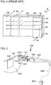
- FIG. 1 shows a light-guide optical element 20 having a pair of parallel faces 26, 26A for guiding light by internal reflection.
- a projected image 18 as represented here schematically by a beam of illumination 18 including sample rays 18A, 18B and 18C which span the beam, is coupled into the light-guide optical element, as illustrated here schematically by a first reflecting surface 16, so as to generate reflected rays 28 which are trapped by internal reflection within the substrate, generating also rays 30.
- the image propagates along the substrate by repeated internal reflection, impinging on a sequence of partially reflecting surfaces 22 at an oblique angle to the parallel faces 26, 26A, where part of the image intensity is reflected so as to be coupled out of the substrate as rays 48A, 48B.
- the partially reflecting surfaces 22 are preferably coated so as to have low reflectance for a first range of incident angles, while having the desired partial reflectivity for a second range of incident angles, for example, as illustrated in FIGS. 2A and 2B , where a ray 32 with a small inclination to the normal to a partially reflective surface 34 is split in order to generate a reflected ray for coupling out ( FIG. 2A ), while a high inclination (to the normal) ray 36 ( FIG 2B ) is transmitted with negligible reflection.
- FIG. 3 illustrates a corresponding configuration implemented using a diffractive optical element 23 for coupling out of the image, and in the example shown here, another diffractive optical element 17 for coupling in of image 18.
- the diffractive optical elements may be deployed on either the upper or lower surface of the substrate, as is known in the art.
- projected image 18 is a collimated image, i.e., where each pixel is represented by a beam of parallel rays at a corresponding angle, equivalent to light from a scene far from the observer.
- the image is represented here simplistically by rays corresponding to a single point in the image, typically a centroid of the image, but in fact includes a range of angles to each side of this central beam, which are coupled in to the substrate with a corresponding range of angles, and similarly coupled out at corresponding angles, thereby creating a field of view corresponding to parts of the image arriving in different directions to the eye 24 of the observer.
- FIGS. 1 and 3 The aperture multiplication of FIGS. 1 and 3 occurs along one dimension, corresponding to the right-to-left direction of the drawings.
- a similar approach is adopted in two dimensions, such as is illustrated in FIG. 4 .
- a first waveguide 20 a has a coupling-in reflector 16 a and partially-reflective coupling-out surfaces 22 a which provide the optical input to a second waveguide 20 b with a coupling-in reflector 16 b and partially-reflective coupling-out surfaces 22 b .
- an image represented by input ray 90 is multiplied successively in two dimensions to provide an output aperture expanded in two dimensions.
- one or both of the expansions may be performed using diffractive optical elements.
- each input image ray being split into a plurality of spaced apart output rays.
- this is represented by multiple out-coupled rays 48A derived from splitting input ray 18A, and multiple out-coupled rays 48B derived by splitting input ray 18B.
- FIG. 4 The same is true for the two dimensional expansion of FIG. 4 .
- One aspect of the present invention provides an eye tracker and corresponding method for tracking the gaze direction of a human eye based on retinal imaging via a light-guide optical element, particularly suitable for integration as part of a near-eye display.
- an apparatus for deriving a gaze direction of a human eye comprising: (a) a light-guide optical element (LOE) formed from transparent material and having pair of parallel faces for guiding light by internal reflection, one of the parallel faces being deployed in facing relation to the eye; (b) a coupling-in configuration associated with the LOE and configured for coupling-in a proportion of light incident on one of the parallel faces within a coupling-in region so as to propagate within the LOE; (c) focusing optics associated with the LOE and configured for converting sets of parallel light rays propagating within the LOE into converging beams of captured light; (d) an optical sensor deployed for sensing the captured light; and (e) a processing system including at least one processor, the processing system being electrically associated with the optical sensor and configured so as to process signals from the optical sensor to derive a current gaze direction of the eye, wherein the coupling-in configuration is configured to generate rays propagating within
- the coupling-in configuration comprises a plurality of partially-reflective surfaces deployed within the LOE obliquely to the parallel faces.
- the coupling-in configuration comprises a diffractive optical element associated with one of the parallel faces.
- the optical sensor comprises a four-quadrant sensor.
- the optical sensor comprises an array of pixel sensing elements, and wherein the processing system processes outputs from no more than about 104 pixel sensing elements.
- an illumination arrangement deployed to illuminate the eye from the direction of the coupling-in region.
- the illumination arrangement is configured to introduce illumination into the LOE so that the illumination propagates within the LOE by reflection at the pair of parallel surfaces and is coupled out towards the eye by the coupling-in configuration.
- an illumination light-guide element formed from transparent material and having pair of parallel faces for guiding light by internal reflection, the illumination light-guide element being deployed in overlapping relation to the LOE, wherein the illumination arrangement is configured to introduce illumination into the illumination light-guide element so that the illumination propagates within the illumination light-guide element by reflection at the pair of parallel surfaces and is coupled out towards the eye by a coupling-out configuration associated with the illumination light-guide element.
- the illumination arrangement is associated with the processing system, the processing system actuating the illumination arrangement to generate illumination pulses with a pulse duration, and wherein the processing system processes signals derived from the optical sensor corresponding to captured light incident during the pulse duration.
- a passband spectral filter deployed to obstruct light of wavelengths outside a given range of wavelengths from reaching the optical sensor, and wherein the illumination arrangement generates illumination primarily within the given range of wavelengths.
- the given range of wavelengths is in a non-visible region of the electromagnetic radiation spectrum.
- the illumination arrangement comprises a plurality of separately controlled illumination pixels, and wherein the processing system selectively actuates the illumination pixels so as to illuminate selectively along directions corresponding to a selected region of the retina of the eye.
- the selected region of the retina is a region including the optic disc of the eye.
- the processing system is configured to process signals from the optical sensor to derive a center of an intensity distribution corresponding to reflection from the retina of the eye, and thereby to determine the current gaze direction of the eye.
- the processing system is configured to process signals from the optical sensor to detect a location of at least one prominent feature of the retina of the eye, and thereby to determine the current gaze direction of the eye.
- the processing system is configured to process signals from the optical sensor to track a pattern of blood vessels in the retina of the eye, and thereby to determine the current gaze direction of the eye.
- an image projector coupled to the LOE so as to introduce a collimated image into the LOE such that the collimated image propagates via internal reflection within the LOE and is coupled out of the LOE towards the eye by the coupling-in configuration.
- the image projector is associated with the processing system, and wherein the processing system actuates the image projector to generate illumination pulses with a pulse duration, the processing system processing signals derived from the optical sensor corresponding to captured light incident during the pulse duration.
- the processing system generates the pulses so as to correspond to a selected subsection of a projected image, and such that the pulses contribute to perception of the projected image.
- a support configuration for supporting the apparatus relative to the head of a human user such that the LOE is deployed in facing relation to a first eye of the user, the apparatus further comprising: (a) a second-eye light-guide optical element (LOE) formed from transparent material and having pair of parallel faces for guiding light by internal reflection, one of the parallel faces being deployed in facing relation to a second eye of the user; (b) a coupling-in configuration associated with the second-eye LOE and configured for coupling-in a proportion of light incident on one of the parallel faces within a coupling-in region so as to propagate within the LOE; (c) focusing optics associated with the second-eye LOE and configured for converting sets of parallel light rays propagating within the LOE into converging beams of captured light; and (d) a second-eye optical sensor deployed for sensing the captured light, wherein the processing system is further associated electrically associated with the second-eye optical sensor and configured so as to process
- LOE light-guide optical element
- a method comprising the steps of: (a) providing the apparatus according to any of the above variants; and (b) processing signals from the optical sensor to derive a current gaze direction of the eye.
- An embodiment of the present invention provides an apparatus and corresponding method for tracking the gaze direction of a human eye based on retinal imaging via a light-guide optical element, particularly suitable for integration as part of a near-eye display.
- FIGS. 5-23 illustrate various aspects of the structure and operation of an apparatus, generally designated 100, constructed and operative according to various embodiments of the present invention, for deriving a gaze direction of a human eye 150.
- eye tracking arrangement for determining the gaze direction of the user.
- One common approach for performing eye tracking is to sample an image of the eye, typically for the purpose of determining the pupil position within the image, and thereby deriving the orientation of the eye.
- FIGS. 1 or 3 It would be particularly advantageous to employ a light-guide optical element operating on principles similar to those of FIGS. 1 or 3 to sample images for eye tracking.
- the one-to-many relationship from the input image to the output image described above with references to FIGS. 1 and 3 results in a converse many-to-one relationship in sampling light in the reverse direction.
- use the aperture multiplying arrangements of FIGS. 1 or 3 in the reverse direction for sampling an image would perform superposition of a plurality of parallel rays incident on the substrate from different parts of the field of view of the system.
- the present invention provides an apparatus and method which, despite the above challenges, has been found effective for determining an eye gaze direction from light captured by a light-guide optical element, as will now be described.
- certain particularly preferred embodiments of the present invention provide an apparatus 100 for deriving a gaze direction of a human eye 150 which includes a light-guide optical element (LOE) 120 formed from transparent material and having pair of parallel faces 104 a , 104 b for guiding light by internal reflection.
- the LOE 120 is deployed with one of the parallel faces 104 a in facing relation to the eye 150.
- LOE light-guide optical element
- a coupling-in configuration such as a set of partially-reflective surfaces 145, is associated with LOE 120 and configured for coupling-in a proportion of light incident on face 104 a within a coupling-in region so as to propagate within the LOE.
- Focusing optics 106 is associated with LOE 120, directly or indirectly, so as to receive the captured light propagating within LOE 120 and to convert sets of parallel light rays propagating within the LOE into converging beams of captured light.
- Focusing optics 106 is preferably integrated into an optical sensor or "camera" 125 that is deployed for sensing the captured light.
- a processing system 108 including at least one processor, is electrically associated with optical sensor 125, and is configured so as to process signals from optical sensor 125 to derive a current gaze direction of the eye.
- the coupling-in configuration may be any coupling-in arrangement which deflects part of the incident radiation to an angle which propagates through internal reflection within the LOE, and where each ray has a direction indicative of a direction of incidence of the corresponding incident light ray.
- Suitable coupling-in configurations include a set of partially-reflective surfaces 145 as shown, and a diffractive optical element.
- any light reflected from the retinal surface is effectively collimated by the ocular lens (and corrective spectacle lens if present) to form a far-field image, where each feature of the retinal image corresponds to beam of parallel rays of light.
- the retinal image is therefore preserved as the parallel rays are collected by the LOE, directed into the reduced aperture, and focused by focusing optics 106 towards optical sensor 125.
- the sensed image data includes much scattered light from the near-field external surfaces of the eye and surrounding tissue, the near-field illumination is roughly uniformly distributed in angular space, thereby generating a generally flat background noise in the sampled image. Only the modulation and/or features due to the retinal reflected image generates contrast within the image, thereby facilitating determination of the current gaze direction of the observer.
- FIGS. 6A and 6B this shows one non-limiting exemplary implementation of apparatus 100 of the present invention, in which tracking is performed through a near-eye display arrangement employing optical aperture multiplication.
- the configuration as shown is based on a combination of two light-guide optical elements: a first LOE 110 which expands a projector image aperture in a first dimension (right-to-left as shown in FIG. 6B ) and a second LOE 120 which expands the image aperture in a second dimension (top-to-bottom as illustrated here).
- An image projector 102 projects light (depicted as solid arrows) through a polarization-selective beam splitter (PBS) 105 onto into LOE 110.
- PBS polarization-selective beam splitter
- LOE 110 is a "2D waveguide", meaning that it has two mutually-orthogonal pairs of surfaces which serve to guide the image in two dimensions as it propagates along LOE 110.
- LOE 120 is a "1D waveguide”, meaning that it has one pair of parallel major surfaces defining a "slab-type waveguide” which guides the image in one dimension.
- apparatus 100 may be implemented using only one waveguide, LOE 120. The latter case as illustrated here employs a tilted projector coupling-in configuration.
- Coupling of the image out from LOE 110 into LOE 120 is here shown as performed by a series of internal partially reflective surfaces (or "facets") 140 deployed at an oblique inclination to one or both pairs of parallel surfaces of LOE 110. Coupling out from the second LOE 120 towards the eye of the observer is achieved using a second set of internal partially reflective surfaces ("facets") 145 deployed at an oblique angle to the parallel faces of that substrate, as best seen in the side view of FIGS. 6A and 7A .
- the facets in one or both of the LOE's may be replaced by diffractive optical elements, as is known in the art.
- the coupled-out light of the projected image is focused by the eye lens 115 (with the assistance of a spectacle lens 117 if a sight correction needed) to generate a focused image on the retina 120.
- the near-eye display system obtains the line of sight of the observer's eye by imaging patterns that exist on the retina of the observer.
- the observation is performed via waveguides 120 and 110, which are in this case the same waveguides used for projecting an image to the observer's eye.
- the position of the patterns and their motion indicate the current line-of-sight and motion of the eye.
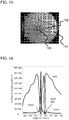
- Such patterns are shown in an image of a retina presented in FIG. 13 .
- the blood vessels 152 generate a pattern that can be tracked by appropriate standard or dedicated tracking algorithm implemented by suitable image processing instructions performed by processing system 108.
- the fovea 155 determines the direction of observation and the optic disc (or "blind spot") 157 is a characteristic trackable point where nerves and blood vessels converge.
- Some of the light is reflected (depicted as dashed arrow) from the retina back through the lens 115, effectively collimating it into a parallel beam, and propagates back along the same optical path taken by light from the projector. A significant part of the light is lost (as discussed further below), but for clarity of presentation, only the part that is useful for tracking is shown.
- Part of the reflected light is deflected by facets 145 so as to be coupled-in to waveguide 120, is deflected at facets 140 so as to be coupled-in to waveguide 110, and some of it is reflected by PBS 105 onto a camera 125.
- a polarization scrambler (not shown) is placed in front of PBS 105.
- Camera 125 is focused to infinity, analogously to projector 102 thereby an image of the retina is generated in the camera.
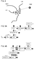
- the various sources of illumination which may play a role in the imaging process are schematically depicted in FIG. 8 .
- the waveguide 120 is deployed in facing relation to the eye of an observer 1001, meaning that the observer's view of a scene passes through the waveguide.
- External light sources 1002 (dashed arrows) illuminate the waveguide and the observer. This external light is continuous and enters the optical system as background radiation.
- the light generated by the optical system (solid arrows) illuminates the retina 121 and the face of the observer.
- the reflections from the retina are the signal of interest while the reflections from non-retina tissue surfaces (dash-dot-dot arrow) are additional background radiation that are intensity-correlated with the illumination pattern of the system. Any internal scattering within the system has the same characteristics as the light scattered from observer's face.
- a short pulse of light (preferably below 1ms) is used, and the camera is synchronized to integrate light only during this short illumination duration. In this manner, continuous background illumination is greatly suppressed.
- a passband spectral filter may be deployed to obstruct light of wavelengths outside a given range of wavelengths within which the eye-tracking illumination is generated from reaching the optical sensor.
- Normal background surface reflects the light to pi steradian (assuming that the surface is a low sheen surface which generates a reflected light distribution approximating to Lambertian reflection), while the pupil generates a directional reflection corresponding to the "red eye” effect often observed in flash photography, reflecting light received from the optical system back into the optical system. Consequently, the intensity of the light received from the retina is stronger than equivalent background surface. Additionally, the image from the retina is focused at the image plane of camera 125 while illumination from nearby "background” surfaces is not. This improves ability to distinguish the image of the retina from image content derived from the background.
- FIGS. 9A and 9B depict the light energy loss of the return path from the eye to tracking camera 125 and for background illumination.
- the pupil of the human eye in bright light is of the order of 4 mm 2
- the eye-box the area within which the image is visible, corresponding to the area illuminated by the system and which generates background reflection
- waveguide edges are preferably absorbing or within an absorbing enclosure. This ensures that background radiation loses energy as it propagates in the optical waveguide, in the same manner as the signal from the retina, and doesn't gain energy.
- the energy transmittance along the optical system can approximated in one non-limiting example as follows:
- the transmittance is higher and, using the above estimations, will be in the order of 2.5e-3.
- a number of approaches may be used to avoid disruption of the displayed image, including one or more of the following:
- the eye tracking illumination may be incorporated as part of the projected image.
- the illumination can be during image projection or in separate time slot as depicted in FIG. 10 .
- the image projector projects an image with missing or suppressed region.
- This illumination can be a relatively long duration, for example in the order of 10ms.
- a complimentary image is illuminated as a short pulse, for example, about 1ms duration, at a higher intensity than the longer pulse, and serves as the eye tracking illumination, in addition to completing the image projection.
- the righthand image represents what is perceived by the brain which integrates the two illumination periods.
- the complimentary image can be in any one of the color separations, or a combination of display colors, and at any selected location or locations within the image.
- One example of preferred "pattern control" for this illumination is described below.
- each pixel corresponds to a broad collimated beam with a particular angular direction.
- time slot 'b' corresponds to illumination in a small number of selected angular directions within the field of view.
- Illumination pattern control Particularly where the image generator 102 (in FIG. 6B or 7B ) is used to generate the eye tracking illumination, it is possible to conveniently control the illumination pattern on the retina, thereby illuminating only a region of interest and reducing disruption to the perceived image. In order to do so, the time sequence of illumination should be combined with the image projection timing. An example of time management of such an implementation is depicted in FIG. 11 .
- a set of light sources are activated in sequence in order to generate all colors. When each light source is illuminating, a modulation matrix (LCOS, LCD or MEMS) generates the required image of this color.
- LCOS modulation matrix
- an additional time slot is introduced into the sequence of illumination (labeled 'eye tracker pulse').
- one of the sources (colors), or a combination of sources, and/or a dedicated eye-tracking wavelength source (discussed below) is activated as a short pulse and its illumination pattern is determined by the modulator to illuminate only required sections of the retina.
- the eye tracking camera 125 is actuated by processing system 108 to integrate photoelectrons only during this pulse time.
- This selected illumination pattern reduces significantly the background noise, since the selected regions of the retina to be tracked are fully illuminated, but the total amount of radiation delivered diffusely to the eye-box area is reduced according to the proportion of pixels that are "active" in the image.
- the illumination pattern can be concentrated only at specific points of interest on the retina, for example at the optic disc ("blind spot" 157 in FIG. 13 ), which has a characteristic blood vessels pattern but minimal sensitivity to light.
- the actual line of sight of the observer is calculated as an angular offset from this point.
- a non-limiting but particularly preferred process for deriving and tracking the actual line of sight is depicted in FIG. 12 .
- the first three steps are an initial setup process for mapping the retina pattern and determining tracking features, while the subsequent steps represent a continuous tracking process.
- an image marker is displayed to the observer for the observer to look at during initialization.
- the fundus (visible portion of the retina) is illuminated fully by short pulses (step 212 ) and a full image of the fundus obtained.
- This image is then processed by processing system 108 to identify trackable features, typically including the optic disc and the fovea (step 214 ).
- Ongoing tracking of the eye direction then proceeds as follows. Selected regions of interest (ROI) are selectively illuminated, typically by sequences of illumination as described above with reference to FIGS. 10 and 11 (step 216 ), and an image is sampled during the corresponding illumination pulse (step 218 ).
- ROI selected regions of interest
- the resulting image is processed to determine the current line of sight (step 222 ), and this derived line of sight is used to update the position of the regions of interest (step 224 ) for the subsequent cycle of illumination cycle, and the tracking process returns to step 216.
- this update process is typically effective to maintain continuous tracking, optionally combined with tracking information from the other eye.
- Updating of the regions of interest may be performed according to the "current" gaze direction as determined from the last sampled image or, in certain cases, may use predictive extrapolation based on eye motion between the previous two or more measurements. In the event that tracking fails, the size of the illuminated region can be temporarily increased until the trackable features are recovered.
- the eye tracking arrangement is duplicated for tracking both eyes of a subject simultaneously.
- the optic disc 157 may be visible to the tracker in one eye and not the other. If a tracking algorithm is used which employs tracking of the blind spot, simultaneous tracking for both eyes allows the tracking to be maintained continuously through periods in which only one eye-tracker can track the blind spot.
- Wavelength selection can also be used for minimizing stimulation of the eye during eye-tracking illumination.
- rod cells are primarily responsible for the peripheral vision and are absent from the fovea.
- Rod cells are relatively insensitive to red (above 620 nanometers), as shown by graph 'R' in FIG. 16 .
- the reduced number of cones that are present in the peripheral region are much less sensitive to low light levels than rods. Therefore, according to certain implementations of the invention, it is preferable to illuminate the peripheral retina (i.e., other than the fovea) with red light for the eye tracking.
- Longer wavelengths (900 nm for example) has up to 6 times more reflectivity than in the visible range, and can be used according to the present invention. This however requires optimization of the optical coatings in order to ensure that the required reflectivity of the various surfaces is suited also to the eye tracker wavelength.
- infrared illumination is used for the eye tracker
- infrared illumination may be combined as a fourth "color" in the conventional visible image projection arrangement, for example, using an LCOS modulator.
- a digital light processing (DPL) device is typically preferred for non-patterned illumination.
- a dedicated illumination source is typically provided independent of the image projector.
- FIGS. 17A-20 illustrate certain implementation options for apparatus according to the present invention incorporating IR illumination into the optical system.
- this relates to an implementation in which near infrared illumination is delivered by integration of a near-infrared source into the visible image projector arrangement as an extra "color". Details of the projector are not shown, but will be self-explanatory to one ordinarily skilled in the art.
- the eye detection camera is in this case placed adjacent to the upper waveguide 110 so that PBS 105 of FIG. 6B is not needed.
- This configuration is based on the fact that the internal facets 140 in LOE 110 couple upward the light that propagates from left to right. In this configuration, it is possible to introduce a polarizer 126, in order to minimize transmission of scattering.
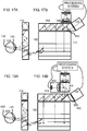
- FIGS. 18A and 18B illustrate a further configuration in which a light source 302 having a wavelength different from the output of image projector 102 (can be IR or VIS, hereafter referred to as IR) transmits the light through a beam splitter 304 (which may be for example a 50/50 beam splitter or a PBS) into waveguide 110.
- the first facet 306 is designed to transmit all or most of visible light from the image projector 102 but is reflective for the IR light for the eye tracker.
- the IR illuminating light propagates to the eye and back as described in FIGS. 6A and 6B . It is then reflected by 306 to the beam splitter 304 and transferred to imaging camera 125.
- the returned light (dashed arrows) is reflected directly into the imaging camera 125 by transmission through waveguide 110 without being reflected and guided by this waveguide.
- This may require a wider receiving optics (similar to the arrangements used in a single waveguide projection arrangement such as in FIGS. 7A and 7B ) and/or may have smaller receiving eye-box than the projector.
- the smaller eye-box is typically acceptable since (unlike the image projector) reflection from the eye can be at off-axis angles, as discussed further below with reference to FIGS. 21A-21C .
- the illumination can be from the image projector or from a dedicated illuminator 302 as shown.
- FIG. 19 shows schematically further details of a possible implementation of projection system 102 for introducing IR illumination along with the visible (VIS) image projection.
- Light from VIS LED 400 passes through light pipe 402 (optional feature for enhancing uniformity), through illumination optics 404, through beam splitter 406 and onto LCOS 408. If the LCOS has embedded color filter per pixel then there is no light pipe in the system and the illumination is by white VIS LED.
- the IR LED 410 for eye-tracking is introduced through dichroic splitter 412. The IR LED is illuminating in sequence or simultaneously with the VIS LED.
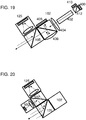
- FIG. 20 illustrates a further option, corresponding to the configuration shown in FIG. 6B .
- 102 is the image projection optics (not shown in detail) and 105 is a beam splitter.
- 105 is preferably a dichroic beam splitter that transmits the visible light from the projector but reflects the IR light to and from the eye-tracking system.
- a dichroic beam splitter with the opposite properties can be used to construct an equivalent configuration with the IR tracking system in the transmitted direction.
- the IR illumination for the eye-tracking system is generated by an IR LED 500, the light passes through a beam splitter 502 (which may be a 50/50 beam splitter or a PBS) onto dichroic splitter 105 and reflected onto the waveguide (adjacent to beam splitter 105 but not shown in this drawing).
- the reflected light (dashed arrows) follows the reverse path and passes through beam splitter 502 onto the IR camera 125.
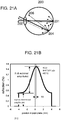
- the reflection from the retina typically includes both a specular component and a diffuse, as illustrated in FIGS. 21B and 21C .
- a simplified model of the eye 200 in FIG. 21A shows an on-axis light ray impinging perpendicularly on the center of the retina 201.
- the strong specular reflection 202 is reflected through the entrance pupil therefore this reflection is strongly detected externally.
- the specular reflection 206 does not exit the pupil and only the defused reflection exits the pupil (marked as a dashed arrow). This is a much weaker signal to be detected externally.
- the graph of FIG. 21B shows schematically the combined reflection intensity.
- the specular reflection component (characterized as variable amplitude A) is angularly dependent (here described as pupil position) while the diffuse reflection is roughly constant (characterized as amplitude B).
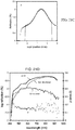
- the graphs of FIGS. 21C and 21D show experimental measurements and wavelength dependency for the components of the reflection. According to these experiments, the full-width at half maximum (FWHM) of the reflection is approximately a 2mm pupil shift, corresponding to roughly ⁇ 10°.
- the actual resolution of the detection can be approximated as: D ⁇ ⁇ ⁇ FWHM / SNR
- the eye orientation resolution can be 1° to 0.1°.
- Signal processing for accurate orientation detection is known and an example is described in the paper " Sampling-balanced imaging system utilizing whitening matched filter" by Y. Danziger, Applied Optics Vol. 49, Issue 17, pp. 3330-3337 (2010 ).
- the envelope of the intensity of the reflection from the eye back into the waveguide of the present invention will be angularly limited. This characteristic is used by certain implementations of the present invention to determine the orientation of the eye (independently from pattern detection).
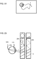
- the entire field of view is preferably illuminated while only part is reflected by the eye.
- FIG. 22 depicts schematically the reflected field where the circle represents the strong specular reflection of the retina while the surrounding is weakly reflected. Therefore, the retina patters will be very visible within this circle but less apparent outside (depicted as dashed lines). According to this invention, the orientation of the eye will be observed as movement of the patterns and of the "envelope" of high reflection.
- envelope detection of the sort described here requires much lower resolution, and may be performed using a four-quadrant or "quadrature” detector, or a low pixel count detector of less than 10 4 pixels, and typically no more than 50x50 pixels, such as is common in an optical computer mouse.
- the reduction in the number of sensor elements allows the use of highspeed graphics processing, which in turn contributes to the response speed of the tracking process.
- an augmented near-eye display 250 can be any type that delivers an image illuminates the eye.
- it is shown as employing a combination of a 2D waveguide and a 1D waveguide, all based on partially-reflective facets, but all of the additional options mentioned above apply here also.
- the dot-dash arrows represent one scattering point (of which can be many) that could saturate combined transmitter/receiver waveguide.
- the illumination can be with a visible illumination or by IR wavelength.
- the reflected light from the eye is collected by a parallel waveguide 255 (shown in side view), distinct from the illumination light-guide element.
- both light-guide optical elements are as described above, formed from transparent material and having pair of parallel faces for guiding light by internal reflection, and are deployed in overlapping relation in facing relation to the eye of the observer.
- the reflected light passes through the illumination waveguide 250 (that is anyway implemented to be mostly transparent in order to allow the observer to see the real world) and into the receiver waveguide 255.
- This waveguide is also mostly transparent, but also includes a coupling mechanism (facets or diffractive) for coupling part of the radiation into the waveguide.
- the reflected image propagates within this waveguide 255 and is collected by the receiver much the same way as previously described for the combined system.
- apparatus 100 is implemented in an eye-glasses form factor with side arms 600 for engaging the ears of the observer, although other form factors such as helmet-mounting etc. also clearly fall within the scope of the present invention.
- Processing system 108 may be implemented using any suitable type of processing hardware and/or software, as is known in the art, including but not limited to any combination of various dedicated graphics processors, display drivers, and general purpose processors operating under any suitable operating system and implementing suitable software or firmware modules.
- Processing system 108 typically also includes various volatile data storage and various communications components for allowing wired or wireless communication with LAN and/or WAN devices for bidirectional transfer of information and graphic content.
- the apparatus is powered from a suitable electrical power source, which may be any combination of batteries and/or an external power source provided, illustrated here schematically as power source 602 connected via a cable 604. Where battery power is used, the batteries may be integrated as part of the eye-glasses or helmet-mounted structure.
- a suitable electrical power source which may be any combination of batteries and/or an external power source provided, illustrated here schematically as power source 602 connected via a cable 604.
- the batteries may be integrated as part of the eye-glasses or helmet-mounted structure.
- the eye tracking of the present invention fundamentally determines the angular orientation (i.e., gaze direction or "line of sight") of the eye, but is in most embodiments essentially insensitive to the spatial position of the eye relative to the apparatus, as long as the eye remains within the effective eye-box of the LOE coverage.
- the apparatus exhibits profound advantages for eye-glasses type or other head-mounted devices and/or other wearable devices for which it is not always feasible to ensure precise and repeatable alignment of the system with the head, and/or where the system may move somewhat relative to the eyes during use.
- the overall device may provide either monocular or binocular image projection and tracking, where binocular is particularly preferred for both.
- binocular is particularly preferred for both.
- various processing and power-supply components may optionally be shared by the two tracking systems, and tracking information is preferably fused in order to provide enhanced stability and continuity of tracking, as discussed above.
Claims (20)
- Appareil (100) pour obtenir une direction de regard d'un œil humain (150), l'appareil comprenant :(a) un élément optique de guidage de lumière, ou LOE, (120) formé à partir de matériau transparent et ayant une paire de faces parallèles (104a, 104b) pour guider de la lumière par réflexion interne, l'une desdites faces parallèles étant déployée en relation de vis-à-vis par rapport à l'œil ;(b) une configuration de couplage d'entrée (145) associée audit LOE et configurée pour coupler en entrée une proportion de lumière incidente sur l'une desdites faces parallèles à l'intérieur d'une région de couplage d'entrée de façon à se propager à l'intérieur dudit LOE ;(c) une optique de focalisation (106) associée audit LOE et configurée pour convertir des ensembles de rayons lumineux parallèles se propageant à l'intérieur du ledit LOE en rayons convergents de lumière capturée ;(d) un capteur optique (125) déployé pour détecter ladite lumière capturée ; et(e) un système de traitement (108) comprenant au moins un processeur, ledit système de traitement étant associé électriquement audit capteur optique et configuré de façon à traiter des signaux provenant dudit capteur optique pour obtenir une direction de regard courante de l'œil,ladite configuration de couplage d'entrée étant configurée pour générer des rayons se propageant à l'intérieur dudit LOE, chaque rayon ayant une direction indiquant une direction d'incidence d'un rayon lumineux incident correspondant, et
caractérisé par le fait qu'une pluralité de rayons incidents parallèles espacés sont combinés en un unique rayon se propageant à l'intérieur dudit LOE. - Appareil selon la revendication 1, dans lequel ladite configuration de couplage d'entrée comprend une pluralité de surfaces partiellement réfléchissantes déployées à l'intérieur dudit LOE de manière oblique par rapport auxdites faces parallèles.
- Appareil selon la revendication 1, dans lequel ladite configuration de couplage d'entrée comprend un élément optique de diffraction associé à l'une desdites faces parallèles.
- Appareil selon la revendication 1, dans lequel ledit capteur optique comprend un capteur à quatre quadrants.
- Appareil selon la revendication 1, dans lequel ledit capteur optique comprend un réseau d'éléments de détection à pixel, et ledit système de traitement traite des sorties de pas plus d'environ 104 éléments de détection à pixel.
- Appareil selon la revendication 1, comprenant en outre un agencement d'éclairage déployé pour éclairer l'œil depuis la direction de ladite région de couplage d'entrée.
- Appareil selon la revendication 6, dans lequel ledit agencement d'éclairage est configuré pour introduire un éclairage dans ledit LOE de telle sorte que ledit éclairage se propage à l'intérieur dudit LOE par réflexion au niveau de ladite paire de surfaces parallèles, et est couplé en sortie vers l'œil par ladite configuration de couplage d'entrée.
- Appareil selon la revendication 6, comprenant en outre un élément de guidage de lumière d'éclairage formé à partir de matériau transparent et ayant une paire de faces parallèles pour guider de la lumière par réflexion interne, ledit élément de guidage de lumière d'éclairage étant déployé en relation de chevauchement par rapport audit LOE, ledit agencement d'éclairage étant configuré pour introduire un éclairage dans ledit élément de guidage de lumière d'éclairage de telle sorte que ledit éclairage se propage à l'intérieur dudit élément de guidage de lumière d'éclairage par réflexion au niveau de ladite paire de surfaces parallèles et est couplé en sortie vers l'œil par une configuration de couplage en sortie associée audit élément de guidage de lumière d'éclairage.
- Appareil selon la revendication 6, dans lequel ledit agencement d'éclairage est associé audit système de traitement, ledit système de traitement actionnant ledit agencement d'éclairage pour générer des impulsions d'éclairage ayant une durée d'impulsion, et ledit système de traitement traite des signaux obtenus à partir dudit capteur optique correspondant à une lumière capturée incidente pendant ladite durée d'impulsion.
- Appareil selon la revendication 6, comprenant en outre un filtre spectral à bande passante déployé pour empêcher de la lumière de longueurs d'onde hors d'une plage donnée de longueurs d'onde, d'atteindre ledit capteur optique, et ledit agencement d'éclairage génère un éclairage principalement à l'intérieur de ladite plage donnée de longueurs d'onde.
- Appareil selon la revendication 10, dans lequel ladite plage donnée de longueurs d'onde est dans une région non-visible du spectre de rayonnement électromagnétique.
- Appareil selon la revendication 6, dans lequel ledit agencement d'éclairage comprend une pluralité de pixels d'éclairage commandés séparément, et ledit système de traitement actionne de manière sélective lesdits pixels d'éclairage de façon à éclairer de manière sélective selon des directions correspondant à une région sélectionnée de la rétine de l'œil.
- Appareil selon la revendication 12, dans lequel, pendant un suivi en cours de la direction de regard de l'œil, ladite région sélectionnée de la rétine est une région comprenant le disque optique de l'œil.
- Appareil selon la revendication 1, dans lequel ledit système de traitement est configuré pour traiter des signaux provenant dudit capteur optique afin d'obtenir un centre d'une distribution d'intensité correspondant à une réflexion provenant de la rétine de l'œil et, de ce fait, déterminer la direction de regard courante de l'œil.
- Appareil selon la revendication 1, dans lequel ledit système de traitement est configuré pour traiter des signaux provenant dudit capteur optique afin de détecter un emplacement d'au moins une caractéristique majeure de la rétine de l'œil et, de ce fait, déterminer la direction de regard courante de l'œil.
- Appareil selon la revendication 1, dans lequel ledit système de traitement est configuré pour traiter des signaux provenant dudit capteur optique afin de suivre un motif de vaisseaux sanguins dans la rétine de l'œil et, de ce fait, déterminer la direction de regard courante de l'œil.
- Appareil selon la revendication 1, comprenant en outre un projecteur d'image couplé audit LOE de façon à introduire une image collimatée dans ledit LOE de telle sorte que ladite image collimatée se propage par réflexion interne à l'intérieur dudit LOE et est couplée en sortie dudit LOE vers l'œil par ladite configuration de couplage d'entrée.
- Appareil selon la revendication 17, dans lequel ledit projecteur d'image est associé audit système de traitement, et ledit système de traitement actionne ledit projecteur d'image pour générer des impulsions d'éclairage ayant une durée d'impulsion, ledit système de traitement traitant des signaux obtenus à partir dudit capteur optique correspondant à de la lumière capturée incidente pendant ladite durée d'impulsion.
- Appareil selon la revendication 18, dans lequel ledit système traitement génère lesdites impulsions de façon à correspondre à une sous-section sélectionnée d'une image projetée, et de telle sorte que lesdites impulsions contribuent à une perception de l'image projetée.
- Appareil selon la revendication 1, comprenant en outre une configuration de support pour supporter l'appareil par rapport à la tête d'un utilisateur humain de telle sorte que ledit LOE est déployé en relation de vis-à-vis par rapport à un premier œil de l'utilisateur, l'appareil comprenant en outre :(a) un élément optique de guidage de lumière (LOE) de second œil formé à partir de matériau transparent et ayant une paire de faces parallèles pour guider de la lumière par réflexion interne, l'une desdites faces parallèles étant déployée en relation de vis-à-vis par rapport à un second œil de l'utilisateur ;(b) une configuration de couplage d'entrée associée audit LOE de second œil et configurée pour coupler en entrée une proportion de lumière incidente sur l'une desdites faces parallèles à l'intérieur d'une région de couplage d'entrée de façon à se propager à l'intérieur dudit LOE ;(c) une optique de focalisation associée audit LOE de second œil et configurée pour convertir des ensembles de rayons lumineux parallèles se propageant à l'intérieur dudit LOE en rayons convergents de lumière capturée ; et(d) un capteur optique de second œil déployé pour détecter ladite lumière capturée,ledit système de traitement étant en outre associé électriquement audit capteur optique de second œil et configuré pour traiter des signaux provenant desdits capteurs optiques afin d'obtenir une direction de regard courante des yeux de l'utilisateur.
Applications Claiming Priority (2)
| Application Number | Priority Date | Filing Date | Title |
|---|---|---|---|
| US201662441205P | 2016-12-31 | 2016-12-31 | |
| PCT/IL2017/051408 WO2018122859A1 (fr) | 2016-12-31 | 2017-12-31 | Dispositif de suivi oculaire basé sur une imagerie rétinienne par l'intermédiaire d'un guide d'ondes optique |
Publications (3)
| Publication Number | Publication Date |
|---|---|
| EP3397137A1 EP3397137A1 (fr) | 2018-11-07 |
| EP3397137A4 EP3397137A4 (fr) | 2019-01-23 |
| EP3397137B1 true EP3397137B1 (fr) | 2019-10-30 |
Family
ID=62707970
Family Applications (1)
| Application Number | Title | Priority Date | Filing Date |
|---|---|---|---|
| EP17885744.7A Active EP3397137B1 (fr) | 2016-12-31 | 2017-12-31 | Dispositif de suivi oculaire basé sur une imagerie rétinienne par l'intermédiaire d'un guide d'ondes optique |
Country Status (8)
| Country | Link |
|---|---|
| US (3) | US20190056600A1 (fr) |
| EP (1) | EP3397137B1 (fr) |
| JP (1) | JP7274724B2 (fr) |
| KR (1) | KR102296369B1 (fr) |
| CN (2) | CN115145023B (fr) |
| IL (1) | IL260969B (fr) |
| TW (1) | TWI759395B (fr) |
| WO (1) | WO2018122859A1 (fr) |
Families Citing this family (71)
| Publication number | Priority date | Publication date | Assignee | Title |
|---|---|---|---|---|
| US10073264B2 (en) | 2007-08-03 | 2018-09-11 | Lumus Ltd. | Substrate-guide optical device |
| IL166799A (en) | 2005-02-10 | 2014-09-30 | Lumus Ltd | Aluminum shale surfaces for use in a conductive substrate |
| US10048499B2 (en) | 2005-11-08 | 2018-08-14 | Lumus Ltd. | Polarizing optical system |
| IL232197B (en) | 2014-04-23 | 2018-04-30 | Lumus Ltd | Compact head-up display system |
| IL235642B (en) | 2014-11-11 | 2021-08-31 | Lumus Ltd | A compact head-up display system is protected by an element with a super-thin structure |
| IL237337B (en) | 2015-02-19 | 2020-03-31 | Amitai Yaakov | A compact head-up display system with a uniform image |
| AU2017301074B2 (en) | 2016-10-09 | 2022-02-03 | Lumus Ltd | Aperture multiplier using a rectangular waveguide |
| RU2763850C2 (ru) | 2016-11-08 | 2022-01-11 | Люмус Лтд | Световодное устройство с краем, обеспечивающим оптическую отсечку, и соответствующие способы его изготовления |
| US11500143B2 (en) | 2017-01-28 | 2022-11-15 | Lumus Ltd. | Augmented reality imaging system |
| WO2018154576A1 (fr) | 2017-02-22 | 2018-08-30 | Lumus Ltd. | Ensemble optique de guide de lumière |
| KR20230025946A (ko) | 2017-03-22 | 2023-02-23 | 루머스 리미티드 | 중첩 파셋 |
| IL251645B (en) | 2017-04-06 | 2018-08-30 | Lumus Ltd | Waveguide and method of production |
| WO2019016813A1 (fr) | 2017-07-19 | 2019-01-24 | Lumus Ltd. | Éclairage à cristaux liquides sur silicium par l'intermédiaire d'un élément optique guide de lumière |
| CN111183393B (zh) | 2017-09-29 | 2024-03-19 | 鲁姆斯有限公司 | 增强现实显示器 |
| US10627627B2 (en) * | 2017-10-02 | 2020-04-21 | Google Llc | Eye tracking using light guide with faceted combiner |
| CN111133362B (zh) | 2017-10-22 | 2021-12-28 | 鲁姆斯有限公司 | 采用光具座的头戴式增强现实设备 |
| KR102570722B1 (ko) | 2017-11-21 | 2023-08-24 | 루머스 리미티드 | 근안 디스플레이용 광학 조리개 확장 배열 |
| WO2019106637A1 (fr) | 2017-12-03 | 2019-06-06 | Lumus Ltd. | Procédés d'alignement de dispositif optique |
| IL275013B (en) | 2017-12-03 | 2022-08-01 | Lumus Ltd | Method and device for testing an optics device |
| WO2019135169A1 (fr) | 2018-01-02 | 2019-07-11 | Lumus Ltd. | Affichages à réalité augmentée à alignement actif et procédés correspondants |
| US10551544B2 (en) | 2018-01-21 | 2020-02-04 | Lumus Ltd. | Light-guide optical element with multiple-axis internal aperture expansion |
| WO2019197959A1 (fr) | 2018-04-08 | 2019-10-17 | Lumus Ltd. | Caractérisation d'échantillon optique |
| CN112119346B (zh) | 2018-05-14 | 2022-08-19 | 鲁姆斯有限公司 | 用于近眼显示器的具有细分光学孔径的投影仪配置和相应的光学系统 |
| WO2019220386A1 (fr) | 2018-05-17 | 2019-11-21 | Lumus Ltd. | Affichage proche de l'œil comprenant des ensembles projecteurs se chevauchant |
| IL259518B2 (en) | 2018-05-22 | 2023-04-01 | Lumus Ltd | Optical system and method for improving light field uniformity |
| CN112119345A (zh) | 2018-05-23 | 2020-12-22 | 鲁姆斯有限公司 | 包括具有部分反射内表面的光导光学元件的光学系统 |
| US11163166B1 (en) * | 2018-05-23 | 2021-11-02 | Facebook Technologies, Llc | Removable frames for head-mounted display systems |
| CN112313499A (zh) | 2018-06-21 | 2021-02-02 | 鲁姆斯有限公司 | 光导光学元件(loe)的板之间折射率不均匀性的测量技术 |
| US11415812B2 (en) | 2018-06-26 | 2022-08-16 | Lumus Ltd. | Compact collimating optical device and system |
| CN112424670B (zh) | 2018-07-16 | 2023-01-17 | 鲁姆斯有限公司 | 采用偏振内反射器的光导光学元件 |
| EP3826528A4 (fr) * | 2018-07-25 | 2022-07-27 | Natus Medical Incorporated | Suppression en temps réel de reflets de del ir d'une image |
| US11543583B2 (en) | 2018-09-09 | 2023-01-03 | Lumus Ltd. | Optical systems including light-guide optical elements with two-dimensional expansion |
| TWM642752U (zh) | 2018-11-08 | 2023-06-21 | 以色列商魯姆斯有限公司 | 用於將圖像顯示到觀察者的眼睛中的顯示器 |
| CN112969955B (zh) | 2018-11-08 | 2023-05-26 | 鲁姆斯有限公司 | 具有二向色分束器颜色组合器的光学装置和系统 |
| KR20200001026U (ko) | 2018-11-11 | 2020-05-21 | 루머스 리미티드 | 인터미디어트 윈도우를 구비한 근거리 디스플레이 장치 |
| EP3911982B1 (fr) * | 2019-01-20 | 2023-07-05 | Lumus Ltd. | Procédé et appareil d'essai de dispositif optique |
| US10983264B2 (en) | 2019-01-24 | 2021-04-20 | Lumus Ltd. | Optical systems including light-guide optical elements with two-dimensional expansion |
| RU2700373C1 (ru) * | 2019-02-05 | 2019-09-16 | Самсунг Электроникс Ко., Лтд. | Система слежения за поворотом глаза |
| US11861063B2 (en) | 2019-02-05 | 2024-01-02 | Samsung Electronics Co., Ltd. | Eye-tracking device and display apparatus including the same |
| KR102651647B1 (ko) | 2019-03-12 | 2024-03-26 | 루머스 리미티드 | 이미지 프로젝터 |
| EP3733139A1 (fr) * | 2019-05-02 | 2020-11-04 | Gensight Biologics | Appareil et procédé de visualisation pour la projection d'un signal lumineux |
| WO2020225747A1 (fr) * | 2019-05-06 | 2020-11-12 | Lumus Ltd. | Guide de lumière transparent pour visualiser une scène et dispositif d'affichage proche de l'œil |
| US11927872B2 (en) | 2019-06-23 | 2024-03-12 | Lumus Ltd. | Display with foveated optical correction |
| CA3137994A1 (fr) | 2019-06-27 | 2020-12-30 | Lumus Ltd | Appareil et procedes de suivi de l'il sur la base de l'imagerie de l'il par l'intermediaire d'un element optique de guide de lumiere |
| CA3145818C (fr) * | 2019-07-04 | 2023-12-12 | Lumus Ltd. | Guide d'ondes d'image a multiplication de faisceau symetrique |
| CN110488335B (zh) * | 2019-08-13 | 2021-11-23 | Oppo(重庆)智能科技有限公司 | 基于可见光通信的导航方法及系统 |
| CN112558751B (zh) * | 2019-09-25 | 2022-07-01 | 武汉市天蝎科技有限公司 | 一种智能眼镜基于mems和光波导镜片的视线追踪方法 |
| EP4053677A4 (fr) * | 2019-10-30 | 2023-11-01 | Imatrix Holdings Corp. | Dispositif de détection de contact oculaire |
| KR20240008402A (ko) | 2019-11-25 | 2024-01-18 | 루머스 리미티드 | 도파관의 표면을 폴리싱하는 방법 |
| IL270991B (en) | 2019-11-27 | 2020-07-30 | Lumus Ltd | A light guide with an optical element to perform polarization mixing |
| AU2020395978A1 (en) | 2019-12-05 | 2022-06-16 | Lumus Ltd. | Light-guide optical element employing complementary coated partial reflectors, and light-guide optical element having reduced light scattering |
| EP4042232A4 (fr) | 2019-12-08 | 2022-12-28 | Lumus Ltd. | Système optique avec projecteur d'image compact |
| TWI747117B (zh) * | 2019-12-25 | 2021-11-21 | 大陸商常州欣盛半導體技術股份有限公司 | 一種眼球追蹤感測器的線路結構及其加工方法 |
| WO2021137228A1 (fr) * | 2019-12-30 | 2021-07-08 | Lumus Ltd. | Systèmes optiques comprenant des éléments optiques de guidage de lumière ayant une expansion bidimensionnelle |
| KR20220116224A (ko) * | 2019-12-30 | 2022-08-22 | 루머스 리미티드 | 광 도파관을 채용하는 검출 및 거리 측정 시스템 |
| US20220397766A1 (en) * | 2020-02-24 | 2022-12-15 | Lumus Ltd. | Mixed reality combiner |
| WO2021188926A1 (fr) * | 2020-03-20 | 2021-09-23 | Magic Leap, Inc. | Systèmes et procédés d'imagarie et de suivi de la rétine |
| KR20210156613A (ko) * | 2020-06-18 | 2021-12-27 | 삼성전자주식회사 | 증강 현실 글라스 및 그 동작 방법 |
| DE202021104723U1 (de) | 2020-09-11 | 2021-10-18 | Lumus Ltd. | An ein optisches Lichtleiterelement gekoppelter Bildprojektor |
| WO2022117355A1 (fr) * | 2020-12-04 | 2022-06-09 | Ams International Ag | Dispositif d'affichage et procédé de mise en œuvre d'un dispositif d'affichage |
| EP4226205A1 (fr) * | 2020-12-06 | 2023-08-16 | Lumus Ltd. | Système optique comprenant un éclairage sélectif |
| WO2022130372A1 (fr) * | 2020-12-17 | 2022-06-23 | Lumus Ltd. | Méthodes et systèmes d'oculométrie sur la base de l'imagerie de l'œil par le biais d'un élément de collimation et d'un élément guide de lumière |
| US11536555B2 (en) * | 2021-02-03 | 2022-12-27 | Meta Platforms Technologies, Llc | Scanning self-mixing interferometry system and sensor |
| KR20220117548A (ko) * | 2021-02-17 | 2022-08-24 | 삼성전자주식회사 | 시선 추적 방법 및 전자 장치 |
| US11928257B2 (en) * | 2021-02-17 | 2024-03-12 | Samsung Electronics Co., Ltd. | Method and electronic device for tracking eye |
| JP2024510870A (ja) | 2021-03-01 | 2024-03-12 | ルムス エルティーディー. | プロジェクタから導波路へのコンパクトな結合を有する光学システム |
| JP7093591B1 (ja) | 2021-03-24 | 2022-06-30 | 株式会社Qdレーザ | 画像投影装置 |
| EP4232868A4 (fr) * | 2021-05-19 | 2024-04-17 | Lumus Ltd | Moteur optique actif |
| US11741861B1 (en) | 2022-02-08 | 2023-08-29 | Lumus Ltd. | Optical system including selectively activatable facets |
| EP4242725A1 (fr) | 2022-03-09 | 2023-09-13 | TriLite Technologies GmbH | Dispositif d'affichage |
| WO2023224878A1 (fr) * | 2022-05-16 | 2023-11-23 | Apple Inc. | Suivi oculaire à l'aide d'un éclairage rétinien aligné sur une lentille de caméra |
Family Cites Families (91)
| Publication number | Priority date | Publication date | Assignee | Title |
|---|---|---|---|---|
| US4720189A (en) * | 1986-01-07 | 1988-01-19 | Northern Telecom Limited | Eye-position sensor |
| US5270748A (en) | 1992-01-30 | 1993-12-14 | Mak Technologies, Inc. | High-speed eye tracking device and method |
| JPH08313843A (ja) * | 1995-05-16 | 1996-11-29 | Agency Of Ind Science & Technol | 視線追従方式による広視野高解像度映像提示装置 |
| DE19713138A1 (de) * | 1997-03-27 | 1998-10-01 | Zeiss Carl Jena Gmbh | Anordnung zur Ermittlung optisch relevanter Daten des Auges |
| JPH10307314A (ja) * | 1997-05-09 | 1998-11-17 | Canon Inc | 観察光学装置 |
| US6154321A (en) | 1998-01-20 | 2000-11-28 | University Of Washington | Virtual retinal display with eye tracking |
| US6580529B1 (en) * | 1998-04-02 | 2003-06-17 | Elop Electro -Optics Industries Ltd. | Holographic optical devices |
| JP2003520984A (ja) | 1999-10-14 | 2003-07-08 | ストラトス プロダクト ディヴェロップメント エルエルシー | 仮想画像システム |
| WO2001095027A2 (fr) * | 2000-06-05 | 2001-12-13 | Lumus Ltd. | Dilatateur de faisceau optique guide par un substrat |
| DE10103922A1 (de) * | 2001-01-30 | 2002-08-01 | Physoptics Opto Electronic Gmb | Interaktives Datensicht- und Bediensystem |
| US6927694B1 (en) | 2001-08-20 | 2005-08-09 | Research Foundation Of The University Of Central Florida | Algorithm for monitoring head/eye motion for driver alertness with one camera |
| US20070165192A1 (en) | 2006-01-13 | 2007-07-19 | Silicon Optix Inc. | Reduced field angle projection display system |
| ITTO20020625A1 (it) * | 2002-07-17 | 2004-01-19 | Fiat Ricerche | Guida di luce per dispositivi di visualizzazione di tipo "head-mounted" o "head-up" |
| US20060132914A1 (en) * | 2003-06-10 | 2006-06-22 | Victor Weiss | Method and system for displaying an informative image against a background image |
| IL157837A (en) | 2003-09-10 | 2012-12-31 | Yaakov Amitai | Substrate-guided optical device particularly for three-dimensional displays |
| US7573640B2 (en) * | 2005-04-04 | 2009-08-11 | Mirage Innovations Ltd. | Multi-plane optical apparatus |
| EP1983884B1 (fr) | 2006-01-26 | 2016-10-26 | Nokia Technologies Oy | Dispositif de poursuite oculaire |
| FR2903503B1 (fr) | 2006-07-06 | 2009-06-12 | Essilor Int | Lentille ophtalmique a insert optique integre destine a permettre la projection d'informations |
| US7394841B1 (en) * | 2007-01-18 | 2008-07-01 | Epicrystals Oy | Light emitting device for visual applications |
| US7850306B2 (en) * | 2008-08-28 | 2010-12-14 | Nokia Corporation | Visual cognition aware display and visual data transmission architecture |
| US20120081800A1 (en) | 2009-04-20 | 2012-04-05 | Dewen Cheng | Optical see-through free-form head-mounted display |
| KR20110050929A (ko) * | 2009-11-09 | 2011-05-17 | 삼성전자주식회사 | 착용형 디스플레이장치 |
| US20130094712A1 (en) | 2010-07-16 | 2013-04-18 | Amir Said | Systems and methods for eye tracking using retroreflector-encoded information |
| JP5499985B2 (ja) * | 2010-08-09 | 2014-05-21 | ソニー株式会社 | 表示装置組立体 |
| US9632315B2 (en) | 2010-10-21 | 2017-04-25 | Lockheed Martin Corporation | Head-mounted display apparatus employing one or more fresnel lenses |
| US9304319B2 (en) | 2010-11-18 | 2016-04-05 | Microsoft Technology Licensing, Llc | Automatic focus improvement for augmented reality displays |
| EP2656135B1 (fr) | 2010-12-24 | 2022-05-04 | Magic Leap, Inc. | Prisme de guide d'ondes de forme libre |
| US8939579B2 (en) * | 2011-01-28 | 2015-01-27 | Light Prescriptions Innovators, Llc | Autofocusing eyewear, especially for presbyopia correction |
| JP4926300B1 (ja) * | 2011-06-10 | 2012-05-09 | パイオニア株式会社 | 画像表示装置、画像表示方法及び画像表示プログラム |
| TW201300834A (zh) * | 2011-06-23 | 2013-01-01 | Seereal Technologies Sa | 顯示裝置,尤其是頭戴式顯示器或護目鏡 |
| US8519607B2 (en) | 2011-06-28 | 2013-08-27 | Federal-Mogul Ignition Company | Spark plug electrode configuration |
| TW201302600A (zh) | 2011-07-04 | 2013-01-16 | Univ Nat Taiwan Science Tech | 矽奈米線陣列之製作方法 |
| US20130021226A1 (en) | 2011-07-21 | 2013-01-24 | Jonathan Arnold Bell | Wearable display devices |
| US9170425B1 (en) | 2011-08-17 | 2015-10-27 | Lockheed Martin Corporation | Multi-focal augmented reality lenses |
| KR20140066258A (ko) * | 2011-09-26 | 2014-05-30 | 마이크로소프트 코포레이션 | 투시 근안 디스플레이에 대한 센서 입력에 기초한 비디오 디스플레이 수정 |
| US8917453B2 (en) * | 2011-12-23 | 2014-12-23 | Microsoft Corporation | Reflective array waveguide |
| US9720232B2 (en) * | 2012-01-24 | 2017-08-01 | The Arizona Board Of Regents On Behalf Of The University Of Arizona | Compact eye-tracked head-mounted display |
| US9297996B2 (en) | 2012-02-15 | 2016-03-29 | Microsoft Technology Licensing, Llc | Laser illumination scanning |
| JP5960799B2 (ja) | 2012-03-28 | 2016-08-02 | パイオニア株式会社 | ヘッドマウントディスプレイ及び表示方法 |
| US10627623B2 (en) * | 2012-05-03 | 2020-04-21 | Nokia Technologies Oy | Image providing apparatus, method and computer program |
| WO2013167864A1 (fr) | 2012-05-11 | 2013-11-14 | Milan Momcilo Popovich | Dispositif de suivi d'un œil |
| IL219907A (en) * | 2012-05-21 | 2017-08-31 | Lumus Ltd | Integrated head display system with eye tracking |
| US8989535B2 (en) * | 2012-06-04 | 2015-03-24 | Microsoft Technology Licensing, Llc | Multiple waveguide imaging structure |
| WO2014043196A1 (fr) | 2012-09-11 | 2014-03-20 | Magic Leap, Inc | Dispositif ergonomique d'affichage monté sur la tête (hmd) et système optique |
| US9933684B2 (en) * | 2012-11-16 | 2018-04-03 | Rockwell Collins, Inc. | Transparent waveguide display providing upper and lower fields of view having a specific light output aperture configuration |
| US10209517B2 (en) * | 2013-05-20 | 2019-02-19 | Digilens, Inc. | Holographic waveguide eye tracker |
| WO2015012280A1 (fr) * | 2013-07-24 | 2015-01-29 | コニカミノルタ株式会社 | Dispositif de détection de ligne de visée |
| US10345903B2 (en) | 2013-07-30 | 2019-07-09 | Microsoft Technology Licensing, Llc | Feedback for optic positioning in display devices |
| JP6369017B2 (ja) | 2013-12-03 | 2018-08-08 | セイコーエプソン株式会社 | 虚像表示装置 |
| JP6349704B2 (ja) | 2013-12-06 | 2018-07-04 | セイコーエプソン株式会社 | 虚像表示装置 |
| US9459451B2 (en) * | 2013-12-26 | 2016-10-04 | Microsoft Technology Licensing, Llc | Eye tracking apparatus, method and system |
| US20160018650A1 (en) | 2014-01-24 | 2016-01-21 | Osterhout Group, Inc. | See-through computer display systems |
| EP3114525A4 (fr) * | 2014-03-03 | 2018-03-07 | Eyeway Vision Ltd. | Système de projection oculaire |
| NZ762223A (en) | 2014-03-05 | 2022-02-25 | Univ Arizona | Wearable 3d augmented reality display with variable focus and/or object recognition |
| JP6554479B2 (ja) | 2014-03-20 | 2019-07-31 | エシロール・アンテルナシオナル | 拡張現実感のための方法 |
| CN106062616B (zh) | 2014-04-01 | 2019-04-12 | 依视路国际公司 | 被安排成用于输出补充图像的多焦点眼科眼镜片 |
| US10509235B2 (en) | 2014-04-02 | 2019-12-17 | Essilor International | Method of calculating optical characteristics of an optical system according to a given spectacle frame |
| EP3132306A1 (fr) | 2014-04-14 | 2017-02-22 | Essilor International (Compagnie Générale D'Optique) | Procédé de calcul de système optique de verre ophtalmique à foyer progressif qui est agencée pour délivrer en sortie une image supplémentaire |
| WO2015184409A1 (fr) | 2014-05-30 | 2015-12-03 | Magic Leap, Inc. | Procédés et systèmes d'affichage stéréoscopique à l'aide d'un système optique à structure libre doté d'un foyer adressable pour la réalité virtuelle et augmentée |
| US10198865B2 (en) | 2014-07-10 | 2019-02-05 | Seiko Epson Corporation | HMD calibration with direct geometric modeling |
| US9606354B2 (en) * | 2014-07-17 | 2017-03-28 | Google Inc. | Heads-up display with integrated display and imaging system |
| WO2016046514A1 (fr) * | 2014-09-26 | 2016-03-31 | LOKOVIC, Kimberly, Sun | Dispositif de poursuite optique à guide d'ondes holographique |
| EP3237957A1 (fr) * | 2014-12-26 | 2017-11-01 | CY Vision Inc. | Dispositif d'affichage proche de l'oeil |
| US9681804B2 (en) | 2015-01-12 | 2017-06-20 | X Development Llc | Hybrid lens system for head wearable display |
| EP3062142B1 (fr) * | 2015-02-26 | 2018-10-03 | Nokia Technologies OY | Appareil pour un dispositif d'affichage proche |
| US9977241B2 (en) * | 2015-03-17 | 2018-05-22 | Seiko Epson Corporation | Head-mounted display device, control method for head-mounted display device, and computer program |
| EP3286599A4 (fr) | 2015-04-22 | 2018-12-19 | eSIGHT CORP. | Procédés et dispositifs de correction d'aberration optique |
| US9910276B2 (en) | 2015-06-30 | 2018-03-06 | Microsoft Technology Licensing, Llc | Diffractive optical elements with graded edges |
| JP2017108370A (ja) | 2015-07-06 | 2017-06-15 | セイコーエプソン株式会社 | 頭部装着型表示装置およびコンピュータープログラム |
| US10007115B2 (en) | 2015-08-12 | 2018-06-26 | Daqri, Llc | Placement of a computer generated display with focal plane at finite distance using optical devices and a see-through head-mounted display incorporating the same |
| AU2016349895B2 (en) | 2015-11-04 | 2022-01-13 | Magic Leap, Inc. | Light field display metrology |
| US9927614B2 (en) | 2015-12-29 | 2018-03-27 | Microsoft Technology Licensing, Llc | Augmented reality display system with variable focus |
| US10993824B2 (en) | 2016-01-01 | 2021-05-04 | Intact Vascular, Inc. | Delivery device and method of delivery |
| CN105652447B (zh) * | 2016-01-28 | 2018-04-03 | 上海理湃光晶技术有限公司 | 平面波导成像装置和方法 |
| US10473933B2 (en) | 2016-02-19 | 2019-11-12 | Microsoft Technology Licensing, Llc | Waveguide pupil relay |
| KR102530558B1 (ko) | 2016-03-16 | 2023-05-09 | 삼성전자주식회사 | 투시형 디스플레이 장치 |
| US20170277259A1 (en) * | 2016-03-24 | 2017-09-28 | Daqri, Llc | Eye tracking via transparent near eye lens |
| US10705338B2 (en) | 2016-05-02 | 2020-07-07 | Waves Audio Ltd. | Head tracking with adaptive reference |
| EP3296793A1 (fr) | 2016-09-19 | 2018-03-21 | Essilor International | Procédé de détermination d'une fonction optique de correction sur une image virtuelle |
| CN115047627A (zh) | 2017-03-21 | 2022-09-13 | 奇跃公司 | 用于照射空间光调制器的方法、设备和系统 |
| WO2018194962A1 (fr) | 2017-04-17 | 2018-10-25 | Akonia Holographics Llc | Imagerie auxiliaire à miroir oblique |
| WO2019060741A1 (fr) | 2017-09-21 | 2019-03-28 | Magic Leap, Inc. | Affichage à réalité augmentée comportant un guide d'ondes configuré pour capturer des images de l'œil et/ou de l'environnement |
| IL275013B (en) | 2017-12-03 | 2022-08-01 | Lumus Ltd | Method and device for testing an optics device |
| US11112613B2 (en) | 2017-12-18 | 2021-09-07 | Facebook Technologies, Llc | Integrated augmented reality head-mounted display for pupil steering |
| WO2019150461A1 (fr) | 2018-01-31 | 2019-08-08 | 株式会社島津製作所 | Dispositif d'affichage d'image |
| US11053019B2 (en) | 2018-04-19 | 2021-07-06 | The Boeing Company | Hybrid propulsion engines for aircraft |
| US11175518B2 (en) | 2018-05-20 | 2021-11-16 | Neurolens, Inc. | Head-mounted progressive lens simulator |
| CN112969955B (zh) | 2018-11-08 | 2023-05-26 | 鲁姆斯有限公司 | 具有二向色分束器颜色组合器的光学装置和系统 |
| IL264551A (en) | 2019-01-29 | 2020-07-30 | Amitai Yaakov | A compact head-up display system with high efficiency and a small entry key |
| US11202563B2 (en) | 2019-03-07 | 2021-12-21 | Neurolens, Inc. | Guided lens design exploration system for a progressive lens simulator |
| CN114930080A (zh) | 2020-02-02 | 2022-08-19 | 鲁姆斯有限公司 | 用于生产光导光学元件的方法 |
-
2017
- 2017-12-31 JP JP2018536174A patent/JP7274724B2/ja active Active
- 2017-12-31 WO PCT/IL2017/051408 patent/WO2018122859A1/fr active Application Filing
- 2017-12-31 US US16/070,782 patent/US20190056600A1/en not_active Abandoned
- 2017-12-31 EP EP17885744.7A patent/EP3397137B1/fr active Active
- 2017-12-31 CN CN202210384731.5A patent/CN115145023B/zh active Active
- 2017-12-31 KR KR1020187023084A patent/KR102296369B1/ko active IP Right Grant
- 2017-12-31 CN CN201780011686.6A patent/CN108882845B/zh active Active
-
2018
- 2018-01-02 TW TW107100088A patent/TWI759395B/zh active
- 2018-08-02 IL IL260969A patent/IL260969B/en active IP Right Grant
-
2020
- 2020-04-13 US US16/846,633 patent/US20200241308A1/en not_active Abandoned
-
2022
- 2022-04-26 US US17/729,241 patent/US11747635B2/en active Active
Non-Patent Citations (1)
| Title |
|---|
| None * |
Also Published As
| Publication number | Publication date |
|---|---|
| JP2020504832A (ja) | 2020-02-13 |
| TW201831953A (zh) | 2018-09-01 |
| IL260969B (en) | 2018-12-31 |
| KR20190099374A (ko) | 2019-08-27 |
| EP3397137A1 (fr) | 2018-11-07 |
| KR102296369B1 (ko) | 2021-09-01 |
| CN115145023A (zh) | 2022-10-04 |
| US11747635B2 (en) | 2023-09-05 |
| CN108882845B (zh) | 2022-05-03 |
| US20190056600A1 (en) | 2019-02-21 |
| US20220252890A1 (en) | 2022-08-11 |
| EP3397137A4 (fr) | 2019-01-23 |
| WO2018122859A1 (fr) | 2018-07-05 |
| CN115145023B (zh) | 2024-02-09 |
| JP7274724B2 (ja) | 2023-05-17 |
| CN108882845A (zh) | 2018-11-23 |
| US20200241308A1 (en) | 2020-07-30 |
| TWI759395B (zh) | 2022-04-01 |
Similar Documents
| Publication | Publication Date | Title |
|---|---|---|
| US11747635B2 (en) | Eye tracker based on retinal imaging via light-guide optical element | |
| CN109073889B (zh) | 全息波导光学跟踪器 | |
| CN110446965B (zh) | 用于结合光扫描投影仪跟踪眼睛运动的方法和系统 | |
| EP2852859B1 (fr) | Visiocasque avec système de poursuite oculaire intégré | |
| US9529191B2 (en) | Dynamic foveal vision display | |
| JPWO2018122859A5 (fr) | ||
| CN117055231A (zh) | 眼睛投影系统和方法 | |
| US11914161B2 (en) | Apparatus and methods for eye tracking based on eye imaging via light-guide optical element | |
| JP7302592B2 (ja) | 情報検出装置、映像投影装置、情報検出方法、及び映像投影方法 | |
| US20220357583A1 (en) | Optical Systems and Methods for Eye Tracking Based on Redirecting Light from Eye Using an Optical Arrangement Associated with a Light-Guide Optical Element | |
| CN216485801U (zh) | 一种光学成像系统、图像显示装置及增强现实显示设备 | |
| US20240004189A1 (en) | Optical systems and methods for eye tracking based on eye imaging via collimating element and light-guide optical element | |
| WO2022196650A1 (fr) | Système de suivi de ligne de visée et dispositif d'affichage d'image virtuelle | |
| US11237389B1 (en) | Wedge combiner for eye-tracking | |
| GB2608789A (en) | Optical system for eye tracking |
Legal Events
| Date | Code | Title | Description |
|---|---|---|---|
| STAA | Information on the status of an ep patent application or granted ep patent |
Free format text: STATUS: THE INTERNATIONAL PUBLICATION HAS BEEN MADE |
|
| PUAI | Public reference made under article 153(3) epc to a published international application that has entered the european phase |
Free format text: ORIGINAL CODE: 0009012 |
|
| STAA | Information on the status of an ep patent application or granted ep patent |
Free format text: STATUS: REQUEST FOR EXAMINATION WAS MADE |
|
| 17P | Request for examination filed |
Effective date: 20180730 |
|
| AK | Designated contracting states |
Kind code of ref document: A1 Designated state(s): AL AT BE BG CH CY CZ DE DK EE ES FI FR GB GR HR HU IE IS IT LI LT LU LV MC MK MT NL NO PL PT RO RS SE SI SK SM TR |
|
| AX | Request for extension of the european patent |
Extension state: BA ME |
|
| A4 | Supplementary search report drawn up and despatched |
Effective date: 20181221 |
|
| RIC1 | Information provided on ipc code assigned before grant |
Ipc: A61B 3/113 20060101AFI20181217BHEP Ipc: G06K 9/00 20060101ALI20181217BHEP Ipc: G02B 27/00 20060101ALI20181217BHEP Ipc: A61B 3/12 20060101ALI20181217BHEP Ipc: G02B 6/00 20060101ALI20181217BHEP |
|
| RIC1 | Information provided on ipc code assigned before grant |
Ipc: A61B 3/12 20060101ALI20190409BHEP Ipc: A61B 3/113 20060101AFI20190409BHEP Ipc: G02B 6/00 20060101ALI20190409BHEP Ipc: G06K 9/00 20060101ALI20190409BHEP Ipc: G02B 27/00 20060101ALI20190409BHEP |
|
| GRAP | Despatch of communication of intention to grant a patent |
Free format text: ORIGINAL CODE: EPIDOSNIGR1 |
|
| STAA | Information on the status of an ep patent application or granted ep patent |
Free format text: STATUS: GRANT OF PATENT IS INTENDED |
|
| INTG | Intention to grant announced |
Effective date: 20190524 |
|
| GRAS | Grant fee paid |
Free format text: ORIGINAL CODE: EPIDOSNIGR3 |
|
| GRAA | (expected) grant |
Free format text: ORIGINAL CODE: 0009210 |
|
| STAA | Information on the status of an ep patent application or granted ep patent |
Free format text: STATUS: THE PATENT HAS BEEN GRANTED |
|
| AK | Designated contracting states |
Kind code of ref document: B1 Designated state(s): AL AT BE BG CH CY CZ DE DK EE ES FI FR GB GR HR HU IE IS IT LI LT LU LV MC MK MT NL NO PL PT RO RS SE SI SK SM TR |
|
| DAV | Request for validation of the european patent (deleted) | ||
| DAX | Request for extension of the european patent (deleted) | ||
| REG | Reference to a national code |
Ref country code: GB Ref legal event code: FG4D |
|
| REG | Reference to a national code |
Ref country code: CH Ref legal event code: EP |
|
| REG | Reference to a national code |
Ref country code: AT Ref legal event code: REF Ref document number: 1195272 Country of ref document: AT Kind code of ref document: T Effective date: 20191115 |
|
| REG | Reference to a national code |
Ref country code: DE Ref legal event code: R096 Ref document number: 602017008293 Country of ref document: DE |
|
| REG | Reference to a national code |
Ref country code: IE Ref legal event code: FG4D |
|
| REG | Reference to a national code |
Ref country code: CH Ref legal event code: NV Representative=s name: NOVAGRAAF INTERNATIONAL SA, CH |
|
| REG | Reference to a national code |
Ref country code: SE Ref legal event code: TRGR |
|
| REG | Reference to a national code |
Ref country code: NL Ref legal event code: FP |
|
| PGFP | Annual fee paid to national office [announced via postgrant information from national office to epo] |
Ref country code: SE Payment date: 20191217 Year of fee payment: 3 |
|
| REG | Reference to a national code |
Ref country code: LT Ref legal event code: MG4D |
|
| PG25 | Lapsed in a contracting state [announced via postgrant information from national office to epo] |
Ref country code: LT Free format text: LAPSE BECAUSE OF FAILURE TO SUBMIT A TRANSLATION OF THE DESCRIPTION OR TO PAY THE FEE WITHIN THE PRESCRIBED TIME-LIMIT Effective date: 20191030 Ref country code: GR Free format text: LAPSE BECAUSE OF FAILURE TO SUBMIT A TRANSLATION OF THE DESCRIPTION OR TO PAY THE FEE WITHIN THE PRESCRIBED TIME-LIMIT Effective date: 20200131 Ref country code: NO Free format text: LAPSE BECAUSE OF FAILURE TO SUBMIT A TRANSLATION OF THE DESCRIPTION OR TO PAY THE FEE WITHIN THE PRESCRIBED TIME-LIMIT Effective date: 20200130 Ref country code: PL Free format text: LAPSE BECAUSE OF FAILURE TO SUBMIT A TRANSLATION OF THE DESCRIPTION OR TO PAY THE FEE WITHIN THE PRESCRIBED TIME-LIMIT Effective date: 20191030 Ref country code: LV Free format text: LAPSE BECAUSE OF FAILURE TO SUBMIT A TRANSLATION OF THE DESCRIPTION OR TO PAY THE FEE WITHIN THE PRESCRIBED TIME-LIMIT Effective date: 20191030 Ref country code: FI Free format text: LAPSE BECAUSE OF FAILURE TO SUBMIT A TRANSLATION OF THE DESCRIPTION OR TO PAY THE FEE WITHIN THE PRESCRIBED TIME-LIMIT Effective date: 20191030 Ref country code: BG Free format text: LAPSE BECAUSE OF FAILURE TO SUBMIT A TRANSLATION OF THE DESCRIPTION OR TO PAY THE FEE WITHIN THE PRESCRIBED TIME-LIMIT Effective date: 20200130 Ref country code: PT Free format text: LAPSE BECAUSE OF FAILURE TO SUBMIT A TRANSLATION OF THE DESCRIPTION OR TO PAY THE FEE WITHIN THE PRESCRIBED TIME-LIMIT Effective date: 20200302 |
|
| PG25 | Lapsed in a contracting state [announced via postgrant information from national office to epo] |
Ref country code: IS Free format text: LAPSE BECAUSE OF FAILURE TO SUBMIT A TRANSLATION OF THE DESCRIPTION OR TO PAY THE FEE WITHIN THE PRESCRIBED TIME-LIMIT Effective date: 20200229 Ref country code: RS Free format text: LAPSE BECAUSE OF FAILURE TO SUBMIT A TRANSLATION OF THE DESCRIPTION OR TO PAY THE FEE WITHIN THE PRESCRIBED TIME-LIMIT Effective date: 20191030 Ref country code: HR Free format text: LAPSE BECAUSE OF FAILURE TO SUBMIT A TRANSLATION OF THE DESCRIPTION OR TO PAY THE FEE WITHIN THE PRESCRIBED TIME-LIMIT Effective date: 20191030 |
|
| PG25 | Lapsed in a contracting state [announced via postgrant information from national office to epo] |
Ref country code: AL Free format text: LAPSE BECAUSE OF FAILURE TO SUBMIT A TRANSLATION OF THE DESCRIPTION OR TO PAY THE FEE WITHIN THE PRESCRIBED TIME-LIMIT Effective date: 20191030 |
|
| PGFP | Annual fee paid to national office [announced via postgrant information from national office to epo] |
Ref country code: TR Payment date: 20200114 Year of fee payment: 3 |
|
| PG25 | Lapsed in a contracting state [announced via postgrant information from national office to epo] |
Ref country code: CZ Free format text: LAPSE BECAUSE OF FAILURE TO SUBMIT A TRANSLATION OF THE DESCRIPTION OR TO PAY THE FEE WITHIN THE PRESCRIBED TIME-LIMIT Effective date: 20191030 Ref country code: RO Free format text: LAPSE BECAUSE OF FAILURE TO SUBMIT A TRANSLATION OF THE DESCRIPTION OR TO PAY THE FEE WITHIN THE PRESCRIBED TIME-LIMIT Effective date: 20191030 Ref country code: ES Free format text: LAPSE BECAUSE OF FAILURE TO SUBMIT A TRANSLATION OF THE DESCRIPTION OR TO PAY THE FEE WITHIN THE PRESCRIBED TIME-LIMIT Effective date: 20191030 Ref country code: DK Free format text: LAPSE BECAUSE OF FAILURE TO SUBMIT A TRANSLATION OF THE DESCRIPTION OR TO PAY THE FEE WITHIN THE PRESCRIBED TIME-LIMIT Effective date: 20191030 Ref country code: EE Free format text: LAPSE BECAUSE OF FAILURE TO SUBMIT A TRANSLATION OF THE DESCRIPTION OR TO PAY THE FEE WITHIN THE PRESCRIBED TIME-LIMIT Effective date: 20191030 |
|
| REG | Reference to a national code |
Ref country code: DE Ref legal event code: R097 Ref document number: 602017008293 Country of ref document: DE |
|
| REG | Reference to a national code |
Ref country code: AT Ref legal event code: MK05 Ref document number: 1195272 Country of ref document: AT Kind code of ref document: T Effective date: 20191030 |
|
| REG | Reference to a national code |
Ref country code: BE Ref legal event code: MM Effective date: 20191231 |
|
| PG25 | Lapsed in a contracting state [announced via postgrant information from national office to epo] |
Ref country code: SK Free format text: LAPSE BECAUSE OF FAILURE TO SUBMIT A TRANSLATION OF THE DESCRIPTION OR TO PAY THE FEE WITHIN THE PRESCRIBED TIME-LIMIT Effective date: 20191030 Ref country code: MC Free format text: LAPSE BECAUSE OF FAILURE TO SUBMIT A TRANSLATION OF THE DESCRIPTION OR TO PAY THE FEE WITHIN THE PRESCRIBED TIME-LIMIT Effective date: 20191030 Ref country code: SM Free format text: LAPSE BECAUSE OF FAILURE TO SUBMIT A TRANSLATION OF THE DESCRIPTION OR TO PAY THE FEE WITHIN THE PRESCRIBED TIME-LIMIT Effective date: 20191030 |
|
| PLBE | No opposition filed within time limit |
Free format text: ORIGINAL CODE: 0009261 |
|
| STAA | Information on the status of an ep patent application or granted ep patent |
Free format text: STATUS: NO OPPOSITION FILED WITHIN TIME LIMIT |
|
| 26N | No opposition filed |
Effective date: 20200731 |
|
| PG25 | Lapsed in a contracting state [announced via postgrant information from national office to epo] |
Ref country code: IE Free format text: LAPSE BECAUSE OF NON-PAYMENT OF DUE FEES Effective date: 20191231 Ref country code: LU Free format text: LAPSE BECAUSE OF NON-PAYMENT OF DUE FEES Effective date: 20191231 |
|
| PG25 | Lapsed in a contracting state [announced via postgrant information from national office to epo] |
Ref country code: SI Free format text: LAPSE BECAUSE OF FAILURE TO SUBMIT A TRANSLATION OF THE DESCRIPTION OR TO PAY THE FEE WITHIN THE PRESCRIBED TIME-LIMIT Effective date: 20191030 Ref country code: BE Free format text: LAPSE BECAUSE OF NON-PAYMENT OF DUE FEES Effective date: 20191231 Ref country code: AT Free format text: LAPSE BECAUSE OF FAILURE TO SUBMIT A TRANSLATION OF THE DESCRIPTION OR TO PAY THE FEE WITHIN THE PRESCRIBED TIME-LIMIT Effective date: 20191030 |
|
| PGFP | Annual fee paid to national office [announced via postgrant information from national office to epo] |
Ref country code: IT Payment date: 20201231 Year of fee payment: 4 |
|
| PG25 | Lapsed in a contracting state [announced via postgrant information from national office to epo] |
Ref country code: CY Free format text: LAPSE BECAUSE OF FAILURE TO SUBMIT A TRANSLATION OF THE DESCRIPTION OR TO PAY THE FEE WITHIN THE PRESCRIBED TIME-LIMIT Effective date: 20191030 |
|
| PG25 | Lapsed in a contracting state [announced via postgrant information from national office to epo] |
Ref country code: MT Free format text: LAPSE BECAUSE OF FAILURE TO SUBMIT A TRANSLATION OF THE DESCRIPTION OR TO PAY THE FEE WITHIN THE PRESCRIBED TIME-LIMIT Effective date: 20191030 Ref country code: HU Free format text: LAPSE BECAUSE OF FAILURE TO SUBMIT A TRANSLATION OF THE DESCRIPTION OR TO PAY THE FEE WITHIN THE PRESCRIBED TIME-LIMIT; INVALID AB INITIO Effective date: 20171231 |
|
| REG | Reference to a national code |
Ref country code: CH Ref legal event code: PL |
|
| REG | Reference to a national code |
Ref country code: NL Ref legal event code: MM Effective date: 20210101 |
|
| REG | Reference to a national code |
Ref country code: SE Ref legal event code: EUG |
|
| PG25 | Lapsed in a contracting state [announced via postgrant information from national office to epo] |
Ref country code: NL Free format text: LAPSE BECAUSE OF NON-PAYMENT OF DUE FEES Effective date: 20210101 |
|
| PG25 | Lapsed in a contracting state [announced via postgrant information from national office to epo] |
Ref country code: SE Free format text: LAPSE BECAUSE OF NON-PAYMENT OF DUE FEES Effective date: 20210101 Ref country code: CH Free format text: LAPSE BECAUSE OF NON-PAYMENT OF DUE FEES Effective date: 20201231 Ref country code: LI Free format text: LAPSE BECAUSE OF NON-PAYMENT OF DUE FEES Effective date: 20201231 |
|
| PG25 | Lapsed in a contracting state [announced via postgrant information from national office to epo] |
Ref country code: TR Free format text: LAPSE BECAUSE OF NON-PAYMENT OF DUE FEES Effective date: 20201231 Ref country code: MK Free format text: LAPSE BECAUSE OF FAILURE TO SUBMIT A TRANSLATION OF THE DESCRIPTION OR TO PAY THE FEE WITHIN THE PRESCRIBED TIME-LIMIT Effective date: 20191030 |
|
| PG25 | Lapsed in a contracting state [announced via postgrant information from national office to epo] |
Ref country code: IT Free format text: LAPSE BECAUSE OF NON-PAYMENT OF DUE FEES Effective date: 20211231 |
|
| P01 | Opt-out of the competence of the unified patent court (upc) registered |
Effective date: 20230527 |
|
| PGFP | Annual fee paid to national office [announced via postgrant information from national office to epo] |
Ref country code: GB Payment date: 20231220 Year of fee payment: 7 |
|
| PGFP | Annual fee paid to national office [announced via postgrant information from national office to epo] |
Ref country code: FR Payment date: 20231222 Year of fee payment: 7 Ref country code: DE Payment date: 20231214 Year of fee payment: 7 |