EP3396353B1 - Material property testing apparatus and method for in situ testing - Google Patents
Material property testing apparatus and method for in situ testing Download PDFInfo
- Publication number
- EP3396353B1 EP3396353B1 EP16877176.4A EP16877176A EP3396353B1 EP 3396353 B1 EP3396353 B1 EP 3396353B1 EP 16877176 A EP16877176 A EP 16877176A EP 3396353 B1 EP3396353 B1 EP 3396353B1
- Authority
- EP
- European Patent Office
- Prior art keywords
- loading
- stretching
- module
- torsion
- test
- Prior art date
- Legal status (The legal status is an assumption and is not a legal conclusion. Google has not performed a legal analysis and makes no representation as to the accuracy of the status listed.)
- Active
Links
Images




Classifications
-
- G—PHYSICS
- G01—MEASURING; TESTING
- G01N—INVESTIGATING OR ANALYSING MATERIALS BY DETERMINING THEIR CHEMICAL OR PHYSICAL PROPERTIES
- G01N3/00—Investigating strength properties of solid materials by application of mechanical stress
- G01N3/62—Manufacturing, calibrating, or repairing devices used in investigations covered by the preceding subgroups
-
- G—PHYSICS
- G01—MEASURING; TESTING
- G01N—INVESTIGATING OR ANALYSING MATERIALS BY DETERMINING THEIR CHEMICAL OR PHYSICAL PROPERTIES
- G01N3/00—Investigating strength properties of solid materials by application of mechanical stress
-
- G—PHYSICS
- G01—MEASURING; TESTING
- G01N—INVESTIGATING OR ANALYSING MATERIALS BY DETERMINING THEIR CHEMICAL OR PHYSICAL PROPERTIES
- G01N3/00—Investigating strength properties of solid materials by application of mechanical stress
- G01N3/02—Details
- G01N3/06—Special adaptations of indicating or recording means
- G01N3/068—Special adaptations of indicating or recording means with optical indicating or recording means
-
- G—PHYSICS
- G01—MEASURING; TESTING
- G01N—INVESTIGATING OR ANALYSING MATERIALS BY DETERMINING THEIR CHEMICAL OR PHYSICAL PROPERTIES
- G01N3/00—Investigating strength properties of solid materials by application of mechanical stress
- G01N3/08—Investigating strength properties of solid materials by application of mechanical stress by applying steady tensile or compressive forces
- G01N3/18—Performing tests at high or low temperatures
-
- G—PHYSICS
- G01—MEASURING; TESTING
- G01N—INVESTIGATING OR ANALYSING MATERIALS BY DETERMINING THEIR CHEMICAL OR PHYSICAL PROPERTIES
- G01N3/00—Investigating strength properties of solid materials by application of mechanical stress
- G01N3/32—Investigating strength properties of solid materials by application of mechanical stress by applying repeated or pulsating forces
-
- G—PHYSICS
- G01—MEASURING; TESTING
- G01N—INVESTIGATING OR ANALYSING MATERIALS BY DETERMINING THEIR CHEMICAL OR PHYSICAL PROPERTIES
- G01N3/00—Investigating strength properties of solid materials by application of mechanical stress
- G01N3/40—Investigating hardness or rebound hardness
- G01N3/42—Investigating hardness or rebound hardness by performing impressions under a steady load by indentors, e.g. sphere, pyramid
-
- G—PHYSICS
- G01—MEASURING; TESTING
- G01N—INVESTIGATING OR ANALYSING MATERIALS BY DETERMINING THEIR CHEMICAL OR PHYSICAL PROPERTIES
- G01N3/00—Investigating strength properties of solid materials by application of mechanical stress
- G01N3/40—Investigating hardness or rebound hardness
- G01N3/48—Investigating hardness or rebound hardness by performing impressions under impulsive load by indentors, e.g. falling ball
-
- G—PHYSICS
- G01—MEASURING; TESTING
- G01N—INVESTIGATING OR ANALYSING MATERIALS BY DETERMINING THEIR CHEMICAL OR PHYSICAL PROPERTIES
- G01N3/00—Investigating strength properties of solid materials by application of mechanical stress
- G01N3/40—Investigating hardness or rebound hardness
- G01N3/54—Performing tests at high or low temperatures
Definitions
- the present disclosure relates to the field of precise scientific instruments and, more particularly, to a material property in-situ test instrument and method under a composite load mode of mechanical - electric - thermal - magnetic coupling.
- the material microcosmic property in-situ test instrument and method under a composite load mode of mechanical - electric - thermal - magnetic coupling loading conditions according to the present disclosure can provide one or more of the four mechanical loads of "stretching/compression - low cycle fatigue - torsion - bending", can carry out a microcosmic property test under a "stress field - temperature field (high/low temperature) - electric field - magnetic field” multi - physical fields coupling for typical functional materials, and can carry out a parallel loading test in which at most the above seven kinds of loading manner coexist at the same time.
- the dynamic evolution of the indentation curve, hardness and elastic modulus of the material sample under complex load conditions can be accurately measured.
- important data information relating to the material service property, reliability and service life such as the physical property parameters, deformation damage, microstructure change and property evolution of the material during and after the action of complex load may be accurately and dynamically monitored by means of the in-situ monitoring platform. It can provide effective means and methods for material microcosmic mechanical property test under the conditions close to the service conditions.
- the development and application of new materials and new technology is the basis of industrial development, and the continuous development of material science and technology also depends on the in-depth study on the various mechanical and physical properties of materials.
- the testing technology of mechanical properties of the material mainly relates to obtaining the elastic modulus, shear modulus and other macro mechanical parameters of the material.
- various kinds of new materials continue to emerge, and the test analysis of the specificity of these new materials has gradually become a research hotspot in the international academic field and engineering field.
- the traditional material mechanical property test method is difficult to fully reflect the physical characteristics of new materials, especially in the case that materials under the actual operating conditions often operates under the action of a composite load, in which case that various physical properties and mechanical properties of the material will not be assessed on the basis of the property under an individual load test.
- CN 203 551 383 U , CN 204 374 017 U , CN 103 353 431 B and CN 103 499 483 A relate to testing equipment for material samples to be tested for mechanical, mechanical , electrical, thermal or magnetic properties.
- the composite load - multi-physical field loading test platform (1) is integrated with other mechanical loading test modes, and can also construct a physical field environment of the high temperature/low temperature - electric field - magnetic field, wherein it is further possible to realize the analysis on microcosmic mechanical properties of the material by means of press-in detection means; at most, the composite load - multi-physical field coupling loading test of "stretching - fatigue - bending - torsion - high temperature field/low temperature field - electric field - magnetic field” or "compression - bending - torsion - high temperature field/low temperature field - electric field - magnetic field” can be achieved, to simulate abundant experimental environment, and to obtain abundant physical property parameters of the material, and a specific operating condition can also be simulated in which one or more of the functions can be selected to be coupled and loaded.
- the composite load - multi-physical field loading test platform 1, the in-situ monitoring platform 2 and the vacuum chamber 4 are integrated to realize the composite load - multi-physical field coupling loading test and the in-situ monitoring in the vacuum environment;
- the vibration isolation base 3 is integrated in the vacuum chamber 4 to prevent the vibration generated during the operation of the vacuum pump from affecting the in-situ monitoring effect of the instrument; in the case that the vacuum chamber is provided, the composite load - multi-physical field loading test platform 1 is placed on the offset swinging support module 25 of which the offset swinging table 2501 is placed on the heavy load guide rail 2502, and the composite load - multi-physical field loading test platform 1, along with the offset swinging table 2501, is partially withdrawn from the vacuum chamber 4 at the end of the test to facilitate replacement of the material sample; at the same time, a carrier tool cart 6 is connected to the vibration isolation base 3 in the vacuum chamber 4 by docking the guide rails, and the composite load - multi-physical field loading test platform 1 is completely withdrawn out of the vacuum chamber 4 to facilitate
- the stretching/compression loading module 11 adopts a bidirectional stretching structure, and a stretching/compression servo motor 1101 drives a bidirectional screw 1102 to move a torsion-end stretching carriage 1103 and a fatigue-end stretching carriage 1104 so as to ensure the consistence of moving speed and stroke on two sides, applying the stretching/compression load, wherein the stretching/compression loading deformation is measured by a linear grating reading head I 1105 and a linear grating reading head II 1118.
- the torsion loading module 12 includes two portions, i.e. a torsion loading active unit 1201 and a torsion loading fixing unit 1202, and is provided in such a manner that one end thereof can twist and the other end is fixed, wherein the torsion loading active unit 1201 is of a loading end, a torsion servo motor 120104 drives a torsion drive gear 120108 and a torsion driven gear 120109 to drive a active-end clamp body 120116 to realize the loading of the torque, wherein the torsion loading fixing unit 1202 is of a fixed end, the torque is transferred from a fixed-end clamp body 120204 and a connecting shaft 120209 to a stretching - torsion composite sensor 120210 to realize measurement of the stretching force and the torque; the active-end clamp body 120116 and the fixed-end clamp body 120204 are respectively installed with a circular grating reading head I 20117 and a circular grating reading head II 120202, and accurate measurement of twisting angle is achieved by measuring the angle difference read in the tor
- a rotary joint 120106 of the torsion loading active unit 1201 includes a rotary joint stator 120106B and a rotary joint rotor 120106A on which an annular groove communicating with a flow opening in the rotary joint stator 120106B is established, so as to still maintain delivery of fluid when there is a relative rotation between the stator and the rotator; a flow path in the active-end clamp body 120116 is docked with a flow path in the rotary joint 120106 by a connecting flange 120107, achieving the introduction and circulation of the refrigerant fluid when the active-end clamp body 120116 is rotated due to the torsion loading; the low temperature loading module 17 pumps the refrigerant liquid to the flow paths established inside the active-end clamp body 120116 and the fixed-end clamp body 120204 by means of the internal refrigeration flow path inside the active-end clamp body 120116 and the fixed-end clamp body 120204 through the external low temperature refrigeration pump, and the material sample is refrigerated in a heat conduction manner, creating a low temperature test
- An inner frame of a fatigue loading module flexible hinge 1402 of the low cycle fatigue loading module 14 is fixed to a fatigue loading module bottom base 1401, and an outer frame is connected to a connecting plate 120211; a fatigue loading module piezoelectric stack 1403 drives the fixed-end clamp body 120204 by means of the fatigue loading module flexible hinge 1402, the connecting plate 120211, and a stretching - torsion composite sensor 120210 to generate a reciprocating slight displacement of high frequency, achieving the fatigue loading on the stretching material sample 51 under action of a pre-stretching load; under a large stretching load, unloading of the large stretching load is achieved by tightening the screws to fasten an unloading plate 120212 to the connecting plate 120211 and the fatigue-end stretching carriage 1104, preventing the fatigue loading module piezoelectric stack 1403 from being damaged.
- the micro-nano indentation test module 15 achieves initial indentation feed by linear motion of the indentation feed unit 2403, the indentation test module piezoelectric stack 1505 drives the indentation indenter 1509 by an indentation flexible hinge 1502 to effect an accurate feed. Press-in force during press-in process is acquired by an press-in force sensor 1508, and press-in depth of the indentation indenter 1509 is monitored by a capacitive slight displacement sensor 1506.
- the high temperature loading module 16 includes a halogen heating lamp 1601, an adjustment carriage 1602, a halogen lamp mounting plate 1603, the halogen heating lamp 1601 is connected to the halogen lamp mounting plate 1603 by screws and mounted on the adjustment carriage 1602, and the loading of high temperature field is achieved by the halogen heating lamp 1601 irradiating the material sample with a focused light beam.
- the magnetic field loading module 18 includes a lower magnetic yoke 1801, a coil 1802, an upper magnetic yoke 1803, magnetic pole heads 1804, an adjustment carriage guide rail 1805, the loading of the magnetic field is realized by a controllable electromagnet consisting of the lower magnetic yoke 1801, the coil 1802, the upper magnetic yoke 1803, and the magnetic pole heads 1804.
- the two magnetic pole heads 1804 are arranged up and down and are fixed to the lower magnetic yoke 1801 and the upper magnetic yoke 1803, respectively, the material sample is placed between the two magnetic pole heads 1804, and the control of the magnetic field intensity is achieved by adjusting the current loaded on the coil 1802; when a high temperature field function is not needed, the halogen heating lamp 1601 can be removed by means of the adjustment carriage 1602 to prevent the optical path of the in-situ monitoring module from being blocked; the electric field loading module 19 is externally connected to a high voltage direct current power supply, the conductive silver glue is used to connect two wires to two opposite surfaces of the material sample, respectively, and a DC high voltage electric field is applied to two ends of the wire to realize loading of the electric field; the placement of the entire test instrument in the vacuum chamber 4 helps to reduce the breakdown voltage between the two electrodes to increase the electric field intensity in the electric field loading test.
- the in-situ monitoring platform 2 is used to dynamically monitor the deformation damage, microstructure change and property evolution of the material sample under the action of the complex mechanical load and multi-physical field load; through the precise adjustment of the position and posture of the various monitoring modules, the real-time dynamical in-situ monitoring of the microcosmic deformation, damage mechanism, microstructure change and property evolution of the material samples in the complex load condition can be realized;
- the in-situ monitoring platform 2 includes an optical microscopic imaging monitoring module 21, an infrared thermal imaging monitoring module 22, a microscopic Raman spectrum monitoring module 23, a lateral loading observation module 24 and a offset swinging support module 25;
- the optical microscopic imaging monitoring module 21 and the microscopic Raman spectrum monitoring module 23 are arranged on two sides of the composite load - multi-physical field loading test platform 1 and mounted on the vibration isolation base 3;
- the offset swinging support module 25 is mounted on the vibration isolation base 3, providing abundant observation positions for each of the in-situ observation modules while carrying the composite load - multi-
- Position adjustment in three, X, Y and Z, directions can be realized both in the optical microscopic imaging monitoring module 21 and the microscopic Raman spectrum monitoring module 23, and transformation of the display view field and focusing of the imaging instruments are achieved by a X-axis moving unit I 2101 and a X-axis moving unit II 2301, a Y-axis moving unit I 2102 and a Y-axis moving unit II 2302, as well as a Z-axis moving unit I 2104 and a Z-axis moving unit II 2304; the initial monitoring angle and the initial monitoring position of the microscopic Raman spectrometer 2315 is adjusted by adjusting the rotary bracket 2305 and the distance adjustment hand wheel 2313, achieving a more extensive monitoring range; the microscopic Raman spectrometer 2315 is in the form of a built-in CCD of which the rear is integrated with a Raman spectrometer through a standard C interface; a local tiny area is selected from the visible range according to the microscopic image and the texture component
- Another object of the present disclosure is to provide a material property in-situ test method under a composite load mode of mechanical - electric - thermal - magnetic coupling; with respect to a material microcosmic property in-situ test method under a mechanical - electric - thermal - magnetic multi-physical field coupling based on a stretching test, including the following steps: fixing the stretching material sample 51 to the active-end clamp body 120116 and the fixed-end clamp body 120204 by the active-end stretching clamp platen 120115 and the fixed-end stretching clamp platen 120205, and causing the stretching/compression loading module 11 to drive the torsion-end stretching carriage 1103 and the fatigue-end stretching carriage 1104 to reversely move so as to achieve the stretching loading on the stretching material sample 51; wherein the torsion loading on the stretching material sample 51 is achieved by the torsion loading module 12; the stretching strain and the torsion strain of the stretching material sample 51 are measured by the linear grating reading head I 1105 and the circular grating reading head I 120117, respectively, and the
- An object of the present disclosure is to provide a material property in-situ test instrument and method under a composite load mode of mechanical - electric - thermal - magnetic coupling to solve the problem that the material property in-situ test under a mechanical - electric - thermal - magnetic multi - physical field coupling cannot be realized in the existing apparatus.
- the disclosure can realize the integration of other mechanical loading forms and can also construct the multi - physical field coupling condition of the high temperature field/low temperature field - electric field - magnetic field.
- the dynamic evolution of the parameters such as indentation curve, hardness and elastic modulus of the material sample under these complex load conditions can be accurately measured with the in-situ micro-nano indentation test module embedded in the instrument.
- the instrument can achieve any combination of stretching/compression, bending, torsion, low cycle fatigue, temperature field, electric field and magnetic field, and at most can realize the parallel loading test of the above seven kinds of load modes at the same time to provides effective means and methods for the microcosmic mechanical property test in a condition close to the service condition.
- important data information relating to the material service property, reliability and service life such as the physical property parameters, deformation damage, microstructure change and property evolution of the material during and after the action of complex load, can be accurately and dynamically monitored by means of the optical microscopic imaging monitoring module, microscopic Raman monitoring module and other types of in-situ monitoring module that are embedded in the instrument.
- the entire machine is integrated with a vacuum chamber to simulate the more abundant experimental environments, such as low pressure environment, vacuum environment, inert gas environment and so on.
- the loading mode and the experimental conditions according to the disclosure are closer to the actual service situation of the material and the more abundant material property parameters can be obtained so as to provide an effective test method for studying the mechanical properties, physical properties, microstructure topography and material failure mechanism of the material.
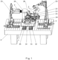
- a material property in-situ test instrument under a composite load mode of mechanical - electric - thermal - magnetic coupling including a composite load - multi-physical field loading test platform 1, an in-situ monitoring platform 2 and a vibration isolation base 3 for supporting the composite load - multi-physical field loading test platform 1 and the in-situ monitoring platform 2 to provide them with a basic installation and positioning and to provide an effective vibration isolation treatment for the test process;
- the vibration isolation base 3 provides the test instrument with an entire machine support and a stable vibration-free test environment; if a vacuum environment is required to be created, the core part, such as the composite load - multi-physical field loading test platform 1, the in-situ monitoring platform 2, can be integrated with the vacuum chamber 4, and the composite load - multi-physical field coupling loading test and the in-situ monitoring in the vacuum environment can be realized;
- the vibration isolation base 3 is integrated in the vacuum chamber 4 to prevent the vibration generated during the operation of the vacuum pump from affecting the in-situ
- the offset swinging support module 25 is arranged in the center of a surface of the vibration isolation base, and the composite load - multi-physical field loading test platform 1 is fixed to the center of the table surface of the offset swinging table 2501 and ensures that the stretching/compression axis is coaxial with the rotation axis of the offset swinging table.
- the mechanical loading platform is based on the stretching/compression load module 11.
- the material microcosmic property in-situ test under the composite load mode of mechanical - electric - thermal - magnetic multi-physical field coupling in the vacuum environment is realized by using the vacuum chamber 4.
- the loading test platform is placed on the offset swinging support module 25 in which the offset swinging table 2501 is placed on the heavy load guide rail 2502, and the loading test platform, along with the offset swinging table 2501, is partially withdrawn from the vacuum chamber 4 at the end of the test to facilitate replacement of the material sample.
- a carrier tool cart 6 is connected to the vibration isolation base 3 in the vacuum chamber 4 by docking the guide rails, and the loading test platform is completely withdrawn out of the vacuum chamber 4 to facilitate the regulation and maintenance thereof.
- the disclosure can realize the integration of other mechanical loading forms and can also construct the multi - physical field coupling condition of the high temperature field/low temperature field - electric field - magnetic field.
- the dynamic evolution of the parameters such as indentation curve, hardness and elastic modulus of the material sample under these complex load conditions can be accurately measured with the in-situ micro-nano indentation test module 15 embedded in the instrument.
- the instrument can achieve any combination of stretching/compression, bending, torsion, low cycle fatigue, temperature field, electric field and magnetic field, and can realize the parallel loading test of the above seven kinds of loading modes at the same time to provides effective means and methods for the material microcosmic mechanical property test in a condition close to the service condition.
- the offset swinging table 2501 of the offset swinging support module 25 is placed on a heavy load guide rail 2502, and the composite load - multi-physical field loading test platform 1, along with the offset swinging table 2501, is partially withdrawn from the vacuum chamber 4 at the end of the test to facilitate replacement of the material sample; at the same time, a carrier tool cart 6 is connected to the vibration isolation base 3 in the vacuum chamber 4 by docking the guide rails, and the composite load - multi-physical field loading test platform 1 is completely withdrawn out of the vacuum chamber 4 to facilitate the regulation and maintenance thereof.
- the composite load - multi-physical field loading test platform 1 applies mechanical loading of multi load modes, such as the stretching/compression, bending, torsion and low cycle fatigue, to the material sample to be tested, and at the same time, precisely detects load signal and deformation signal to realize mechanical property test of the material under the composite load mode; according to the test conditions, the mechanical - electric - thermal - magnetic multi external field load is applied to the material sample to be tested, and precise measurement of the external field loading parameters and the corresponding physical property parameters of the material are achieved; wherein under the coupling action of the composite load - multi-physical field loading test platform 1, a complex load of the mechanical and external field coupling action in a condition close to the service condition is applied to the material sample to be tested, and at the same time, the basic physical property parameters of the material are accurately measured and quantitatively analyzed; and wherein the dynamic evolution of the basic mechanical parameters, such as the hardness and elastic modulus, of the material under various external loads can be measured through a micro-nano indentation
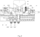
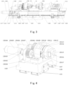
- the composite load - multi-physical field loading test platform 1 includes a stretching/compression loading module 11, a torsion loading module 12, a bending loading module 13, a low cycle fatigue loading module 14, a micro-nano indentation test module 15, a high temperature loading module 16 , a low temperature loading module 17, a magnetic field loading module 18 and an electric field loading module 19, wherein a DC power supply and a circulating refrigeration pump, which are core devices of the low temperature loading module 17 and the electric field loading module 19, are external devices; the reference numerals in Figures 3 and 8 respectively represent wires introduced from the high voltage power supply and flow path introducing the low temperature fluid.
- the above modules can be selected and provided according to the actual requirements.
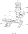
- the stretching/compression loading module 11 is fixed to a table surface of a offset swinging table 2501, and the torsion loading module 12 includes two parts, i.e., a torsion loading active unit 1201 and a torsion loading fixing unit 1202 which are respectively attached to a torsion-end stretching carriage 1103 and a fatigue-end stretching carriage 1104 of the stretching/compression loading module 11; wherein the low cycle fatigue loading module 14 is mounted on the fatigue-end stretching carriage 1104 and is connected to tail of the torsion loading fixing unit 1202; wherein the bending loading module 13, the micro-nano indentation test module 15 and an infrared thermal imaging monitoring module 22 are respectively fixed to a bending feed unit 2401, an indentation feed unit 2403, and an infrared thermal imager feed unit 2402 of a lateral loading observation module 24 by screws in a same manner, and are mounted on a function switching unit 2404 together; wherein reciprocating motion of the function switching unit 2404 realizes positional selection and work station switching of the
- the stretching/compression loading module 11 of the present disclosure adopts a bidirectional stretching structure, and a stretching/compression servo motor 1101 drives a bidirectional screw 1102 to drive a torsion-end stretching carriage 1103 and a fatigue-end stretching carriage 1104 so as to ensure the consistence of moving speed and stroke on two sides, applying the stretching/compression load, wherein the stretching/compression loading deformation is measured by a linear grating reading head I 1105 and a linear grating reading head II 1118.
- the stretching/compression loading module 11 includes the stretching/compression servo motor 1101, and the bidirectional screw 1102, the torsion-end stretching carriage 1103, a stretching motor support base 1108, a coupling 1109, a screw support base assembly 1110, a stretching guide rail 1111, a stretching platform slider 1107, a fatigue-end stretching carriage 1104, a magnetic field loading module positioning key 1112, a linear grating reading head bracket 1113, a linear grating reading head I 1105, a linear grating reading head II 1118, a linear grating ruler I 1106, a linear grating ruler II 1119, a grating ruler fixing sheet 1114, a base plate 1115, a limit switch bracket 1116, a limit switch 1117, nuts I 1120, nuts II 1122, a nut seat I 1121, a nut seat II 1123.
- the base plate 1115 is a fixed portion of the stretching/compression loading module 11.
- the stretching/compression servo motor 1101 is fixed to the base plate 1115 by the stretching motor support base 1108 and the stretching/compression servo motor 1101 is connected to the bidirectional screw 1102 via a coupling 1109.
- the bidirectional screw 1102 is positioned on the base plate 1115 by means of a screw support base assembly 1110.
- the bidirectional screw 1102 and the nuts I 1120 as well as the nuts II 1122 constitute two sets of nut pairs.
- the nuts I 1120 and the nuts II 1122 are fixed to the fatigue-end stretching carriage 1104 and the torsion-end stretching carriage 1103 through the nut seat I 1121 and the nut seat II 1123, respectively.
- the fatigue-end stretching carriage 1104, and the torsion-end stretching carriage 1103 are mounted on the stretching guide rail 1111 by a stretching platform slider 1107.
- the linear grating reading head I 1105 and the linear grating reading head II 1118 are mounted on the fatigue-end stretching carriage 1104 and the torsion-end stretching carriage 1103 through the linear grating reading head bracket 1113, respectively.
- the linear grating ruler I 1106 and the linear grating ruler II 1119 are mounted on the base plate 1115 through a grating ruler fixing sheet 1114.
- the limit switch 1117 is mounted on the base plate 1115 through a limit switch bracket 1116.
- the magnetic field loading module positioning key 1112 is mounted on the base plate 1115.
- the stretching/compression servo motor 1101 drives the bidirectional screw 1102 to rotate to move the nuts I 1120 and the nuts II 1122 at a same speed but in different directions, and drives the fatigue-end stretching carriage 1104 and the torsion-end stretching carriage 1103 to move at a same speed but in different directions.
- the relative motion between the linear grating reading head I 1105 and the linear grating ruler I 1106 as well as that between the linear grating reading head II 1118 and the linear grating ruler II 1119 are utilized to obtain the stretching/compression deformation amount of the material sample.
- the limit switch 1117 prevents the stretching platform slider 1107 from slipping out of the stretching guide rail 1111.
- the torsion loading module 12 includes two portions, i.e., a torsion loading active unit 1201 and a torsion loading fixing unit 1202, and is provided in such a manner that one end thereof can twist and the other end is fixed, wherein the torsion loading active unit 1201 is of a loading end, a torsion servo motor 120104 drives a torsion drive gear 120108 and a torsion driven gear 120109 to drive a active-end clamp body 120116 to realize the loading of the torque; wherein the torsion loading fixing unit 1202 is of a fixed end, the torque is transferred from a fixed-end clamp body 120204 and a connecting shaft 120209 to a stretching - torsion composite sensor 120210 to realize measurement of the stretching force and the torque; the active-end clamp body 120116 and the fixed-end clamp body 120204 are respectively installed with a circular grating reading head I 20117 and a circular grating reading head II 120202
- the torsion loading active unit 1201 includes a torsion bearing frame 120101, a transmission shaft 120102, a torsion motor support base 120103, a torsion servo motor 120104, a rotary joint support base 120105, a rotary joint 120106, a connecting flange 120107, a torsion drive gear 120108, a torsion driven gear 120109, an angular contact bearing end cover 120110, a gasket I 120111, an angular contact bearing seat 120112, an angular contact ball bearing 120113, a circular grating ruler I 120114, an active-end stretching clamp platen 120115, an active-end clamp body 120116, a circular grating reading head 120117, an active-end compression clamp head 120118.
- the motor shaft of the torsion servo motor 120104 is connected to the transmission shaft 120102 by a key, and the torsion drive gear 120108 is connected to the transmission shaft 120102, and the torsion driven gear 120109 is connected to the active-end clamp body 120116 by a key.
- the torsion servo motor 120104 is fixed to the torsion-end stretching carriage 1103 by the torsion motor support base 120103.
- the torsion bearing frame 120101 is fixed to the torsion-end stretching carriage 1103.
- the transmission shaft 120102 is mounted on the torsion bearing frame 120101.
- the rotary joint 120106 includes a rotary joint stator 120106B and a rotary joint rotor 120106A.
- the rotary joint stator 120106B is connected to the rotary joint support base 120105 and the rotary joint rotor 120106A is connected to the active-end clamp body 120116 by means of the connecting flange 120107.
- the active-end clamp body 120116 is mounted on the angular contact bearing seat 120112 by means of one pair of angular contact ball bearings 120113 arranged back to back, the angular contact bearing end cover 120110 and the gasket I 120111 are mounted on the angular contact bearing seat 120112, the angular contact ball bearings 120113 is tightly pressed by the angular contact bearing end cover 120110, and the angular contact bearing seat 120112 is attached to the torsion-end stretching carriage 1103 by screws.
- the circular grating ruler I 120114 is mounted on the active-end clamp body 120116 and the circular grating reading head 120117 is mounted on the angular contact bearing seat 120112.
- the active-end stretching clamp platen 120115 and the active-end compression clamp head 120118 are mounted to the active-end clamp body 120116 for the stretching/compression test so as to clamp the stretching material sample 51/the compression material sample 52.
- the torsion servo motor 120104 transmits the torque from the transmission shaft 120102, the torsion drive gear 120108 and the torsion driven gear 120109 to the active-end clamp body 120116, and drives the material sample to twist.
- the torsion loading fixing unit 1202 includes a circular grating ruler II 120203, a circular grating reading head II 120202, a fixed-end clamp body 120204, a fixed-end stretching clamp platen 120205, a cylindrical roller bearing 120206, a gasket II 120207, a cylindrical roller bearing end cover 120208, a connecting shaft 120209, a stretching - torsion composite sensor 120210, a connecting plate 120211, an unloading plate 120212, a cylindrical roller bearing seat 120201, and a fixed-end compression clamp head 120213.
- the fixed-end clamp body 120204 is mounted on the cylindrical roller bearing seat 120201 by the cylindrical roller bearing 120206, the connecting shaft 120209 is connected to the fixed-end clamp body 120204 and the stretching - torsion composite sensor 120210 at two ends thereof by screws, respectively, and the stretching - torsion composite sensor 120210 is connected to the connecting plate 120211 by screws.
- the cylindrical roller bearing seat 120201 and the unloading plate 120212 are connected to the fatigue-end stretching carriage 1104.
- the cylindrical roller bearing end cover 120208 and the gasket II 120207 are mounted on the cylindrical roller bearing seat 120201.
- the circular grating ruler II 120203 is mounted on the fixed-end clamp body 120204 and the circular grating reading head II 120202 is mounted on the cylindrical roller bearing seat 120201.
- the fixed-end stretching clamp platen 120205 and the fixed-end compression clamp head 120213 are mounted to the fixed-end clamp body 120204 for the stretching/compression test so as to clamp the stretching material sample 51/compression material sample 52.
- the stretching/compression force and the torque are transmitted to the stretching and torsion composite sensor 120210 by the fixed-end clamp body 120204 and the connecting shaft 120209 to realize the measurement of the stretching force/compression force and the torque load.
- the active-end clamp body 120116 and the fixed-end clamp body 120204 are respectively installed with a circular grating ruler I 120114 and a circular grating ruler II 120203.
- the accurate measurement of twisting angle is achieved by measuring the angle difference read in the torsion measurement test with the circular grating reading head I 120117 and the circular grating reading head II 120202. Under a large stretching load, the large stretching load is removed by tightening the screws to fasten an unloading plate 120212 to the connecting plate 120211 and the fatigue-end stretching carriage 1104, preventing the fatigue loading module piezoelectric stack 1403 from being damaged.
- the stretching material sample 51 used in the stretching test is plate-like in shape
- the stretching material sample 51 is tightly caught by the slopes on the fixed-end clamp body 120204 and the active-end clamp body 120116.
- the active-end stretching clamp platen 120115 and the fixed-end stretching clamp platen 120205 are respectively mounted to the clamp bodies on two sides to realize the clamping of the stretching material sample 51.
- the compression material sample 52 used in the compression test is cubic in shape
- the active-end compression clamp head 120118 and the fixed-end compression clamp head 120213 are respectively mounted to the clamp bodies on two sides.
- a square groove is provided in the active-end compression clamp head 120118 and the fixed-end compression clamp head 120213 such that the compression material sample 52 can be caught in the groove to realize the clamping of the compression material sample 52 during the compression, bending and torsion loading.
- the low cycle fatigue loading module 14 of the present disclosure includes a fatigue loading module flexible hinge 1402, a fatigue loading module piezoelectric stack 1403, a fatigue module slider 1404, a fatigue module guide rail 1406, a fatigue loading module bottom base 1401 and an end face fixing plate 1405.
- the fatigue loading module flexible hinge 1402 includes a fixed end and a deformation output end.
- the fixed end of the fatigue loading module flexible hinge 1402 is fixedly connected to the fatigue loading module bottom base 1401 by screws, and the fatigue loading module bottom base 1401 is fixedly connected to the fatigue-end stretching carriage 1104 by the end face fixing plate 1405, the output end of the fatigue loading module flexible hinge 1402 is connected to the torsion loading fixing unit 1202 by screws and is mounted on the fatigue module slider 1404, and the fatigue loading module piezoelectric stack 1403 drives the fatigue loading module flexible hinge 1402 to deform, such that the output end of the fatigue loading module flexible hinge 1402 drives the torsion loading fixing unit 1202 in the direction of the fatigue module guide rail 1406 to generate a slight displacement, achieving a low cycle fatigue loading.
- An inner frame of the fatigue loading module flexible hinge 1402 is fixed to a fatigue loading module bottom base 1401, and an outer frame is connected to a connecting plate 120211; a fatigue loading module piezoelectric stack 1403 drives the fixed-end clamp body 120204 by means of such as the fatigue loading module flexible hinge 1402, the connecting plate 120211, and a stretching - torsion composite sensor 120210 to generate a reciprocating slight displacement in high frequency, effecting the fatigue loading on the stretching material sample 51 under action of a pre-stretching load.
- the bending loading module 13 of the present disclosure includes a bending loading module support base 1301, a support shaft 1304, a pressure sensor 1303, a bending indenter 1302.
- the bending loading module support base 1301, the support shaft 1304, the pressure sensor 1303 and the bending indenter 1302 are successively connected by screws.
- the bending loading module support base 1301 is connected to the bending feed unit 2401 by screws and they are finally fixed to the function switching unit 2404 by screws.
- the function switching unit 2404 drives the bending loading module 13 to achieve an adjustment of the bending work station in the axial direction of the material sample and the bending load is performed by driving the bending indenter 1302 through the motor and the ball screw with the bending feed unit 2401.
- the micro-nano indentation test module 15 of the present disclosure includes a wedged block 1501, an indentation flexible hinge 1502, an indentation test module support base 1503, a fine adjustment unit 1504, an indentation test module piezoelectric stack 1505, a press-in force sensor 1508, a stopping sheet 1507, an indentation indenter 1509, a capacitive slight displacement sensor 1506, wherein the fine adjustment unit 1504 is composed of a movable plate 150401, a displacement sensor bracket 150402, a displacement sensor platen 150403, a fixing plate 150404 and a handle 150405.
- the indentation test module piezoelectric stack 1505 mounted in the indentation flexible hinge 1502 is pre-tightened by the wedged block 1501, and the press-in force sensor 1508 is located and threaded between the indentation indenter 1509 and the indentation flexible hinge 1502.
- the indentation flexible hinge 1502 is mounted on the indentation test module support base 1503.
- the stopping sheet 1507 is mounted on the indentation indenter 1509.
- the fixing plate 150404 is screwed to the indentation test module support base 1503
- the movable plate 150401 is screwed to the displacement sensor bracket 150402, and the displacement sensor platen 150403 clamps the capacitive slight displacement sensor 1506 tightly.
- the operating position of the capacitive slight displacement sensor 1506 is adjusted so as to reach the range ability of the sensor by adjusting the relative position between the movable plate 150401 and the fixing plate 150404 by rotating the handle 150405, and the press-in depth of the indentation indenter 1509 is characterized by measuring the distance of the capacitive slight displacement sensor 1506 from the stopping sheet 1507.
- the function switching unit 2404 drives the micro-nano indentation test module 15 to effect the adjustment of the press-in position in the axial direction of the material sample, and the initial indentation feed is performed by the linear motion of the indentation feed unit 2403.
- the indentation test module piezoelectric stack 1505 drives the indentation indenter 1509 through the indentation flexible hinge 1502 and the press-in force sensor 1508 to achieve a precise feed.
- the press-in force in the press-in process is acquired by the press-in force sensor 1508, and the press-in depth of the indentation indenter 1509 is monitored by means of the capacitive slight displacement sensor 1506.
- the micro-nano indentation test module 15 is embedded in the instrument as a monitoring means of measuring the mechanical properties of the material. It can accurately measure the dynamic evolution of the indentation curve, hardness, elastic modulus and other parameters of the material sample in the local tiny area under the action of complex load conditions.
- the bending loading module 13, the micro-nano indentation test module 15 and the infrared thermal imaging monitoring module 22 are respectively fixed to a bending feed unit 2401, an indentation feed unit 2403, and an infrared thermal imager feed unit 2402 by screws in a same manner, and are mounted on the function switching unit 2404 together. Reciprocating motion of the function switching unit 2404 realizes function switching of the bending loading, indentation loading, and infrared thermal imaging.
- the infrared thermal imaging monitoring module 22 is mounted on the infrared thermal imager feed unit 2402 and the function switching unit 2404 drives the infrared thermal imaging monitoring module 22 to achieve adjustment of the operating position in the infrared imaging in the axial direction of the material sample.
- the focal length adjustment of the infrared thermal imaging monitoring module 22 is realized through the linear motion of the infrared thermal imager feed unit 2402 to reach the purpose of monitoring the temperature distribution of the material samples in the test.
- the low temperature loading module 17 of the present disclosure is implemented by using an external low temperature refrigerating pump opening to a refrigerating flow path.
- Flow paths are established inside the active-end clamp body 120116 and the fixed-end clamp body 120204.
- the refrigerant liquid is pumped to the internal flow path inside the active-end clamp body 120116 and the fixed-end clamp body 120204 through the external low temperature refrigeration pump, and the material sample is refrigerated in a heat conduction manner, creating a low temperature test environment for the material sample.
- a rotary joint 120106 includes a rotary joint stator 120106B and a rotary joint rotor 120106A on which an annular groove communicating with a flow opening in the rotary joint stator 120106B is established, so as to maintain delivery of fluid when there is a relative rotation between the stator and the rotator.
- a flow path in the active-end clamp body 120116 is docked with a flow path in the rotary joint 120106 by a connecting flange 120107, achieving the introduction and circulation of the refrigerant fluid when the active-end clamp body 120116 is rotated due to the torsion loading.
- the clamping operation for the material sample of the present disclosure is mainly carried out by the active-end stretching clamp platen 120115, the active-end clamp body 120116, the fixed-end clamp body 120204, the fixed-end stretching clamp platen 120205, the active-end compression clamp head 120118, and the fixed-end compression clamp head 120213.
- the active-end clamp body 120116 is screwed to the active-end stretching clamp platen 120115 and the active-end compression clamp head 120118
- the fixed-end clamp body 120204 is screwed to the fixed-end stretching clamp platen 120205 and the fixed-end compression clamp head 120213.
- the active-end clamp body 120116 and the fixed-end clamp body 120204 of the stretching clamp are designed with side structures cooperating with the clamping end of the stretching material sample 51.
- the material sample in stretching is positioned by the two side surfaces, and the material sample is tightly pressed by the active-end stretching clamp platen 120115 and the fixed-end stretching clamp platen 120205, achieving a reliable clamping of the stretching material sample 51.
- the active-end compression clamp head 120118 and the fixed-end compression clamp head 120213 are designed with grooves which cooperate with two ends of the compression material sample 52 and the material sample is pressed against the active-end compression clamp head 120118 and the fixed-end compression clamp head 120213 by means of gravity.
- the two end surfaces of the compression material sample 52 are tightly pressed by the active-end compression clamp head 120118 and the fixed-end compression clamp head 120213, achieving a reliable clamping of the compression material sample 51.
- the high temperature loading module 16 of the present disclosure includes a halogen heating lamp 1601, an adjustment carriage 1602, a halogen lamp mounting plate 1603.
- the halogen heating lamp 1601 is connected to the halogen lamp mounting plate 1603 by screws and is mounted on the adjustment carriage 1602.
- the adjustment carriage 1602 can adjust the focal length of the halogen heating lamp 1601 along the adjustment carriage guide rail 1805.
- the halogen heating lamp 1601 emits light and focuses it on the surface of the material sample by the arcuate surface to achieve high temperature loading.
- the magnetic field loading module 18 includes a lower magnetic yoke 1801, a coil 1802, an upper magnetic yoke 1803, magnetic pole heads 1804 and an adjustment carriage guide rail 1805. Two magnetic pole heads 1804 are arranged up and down and are fixed to the lower magnetic yoke 1801 and the upper magnetic yoke 1803, respectively.
- the loading of the vertical magnetic field on the material sample is realized by loading current on the coil 1802.
- the loading of high temperature field is achieved by the halogen heating lamp 1601 irradiating the material sample by a focused light.
- the loading of the magnetic field may be realized by a controllable electromagnet consisting of the lower magnetic yoke 1801, the coil 1802, the upper magnetic yoke 1803, and the magnetic pole heads 1804.
- the material sample is placed between the two magnetic pole heads 1804, and the control of the magnetic field intensity is achieved by adjusting the current loaded on the coil 1802; when a high temperature field function is not needed, the halogen heating lamp 1601 can be removed by means of the adjustment carriage 1602 to prevent the optical path of the in-situ monitoring module from being blocked.
- the electric field loading module 19 It is necessary for the electric field loading module 19 to be externally connected to a high voltage direct current power supply, the conductive silver glue is used to connect two wires to two opposite surfaces of the material sample, respectively, and a DC high voltage electric field is applied to two ends of the wire to realize loading of the electric field.
- the arrangement of the entire test instrument in the vacuum chamber 4 helps to reduce the breakdown voltage between the two electrodes and can increase the electric field intensity in the electric field loading test.
- the in-situ monitoring platform 2 is used to dynamically monitor the deformation damage, microstructure change and property evolution of the material sample under the action of the complex mechanical load and multi-physical field load; and through precise adjustment of the position and posture of the various monitoring modules, the real-time dynamical in-situ monitoring of the microcosmic deformation, damage mechanism, microstructure change and property evolution of the material samples in the complex load condition can be realized.
- the in-situ monitoring platform 2 includes an optical microscopic imaging monitoring module 21, an infrared thermal imaging monitoring module 22, a microscopic Raman spectrum monitoring module 23, a lateral loading observation module 24 and an offset swinging support module 25.
- the optical microscopic imaging monitoring module 21 and the microscopic Raman spectrum monitoring module 23 are arranged on two sides of the composite load - multi-physical field loading test platform 1 and mounted on the vibration isolation base 3; the offset swinging support module 25 is mounted on the vibration isolation base 3, providing abundant observation positions for each of the in-situ observation modules while carrying the composite load - multi-physical field loading test platform 1.
- the infrared thermal imaging monitoring module 22 is mounted on the lateral loading observation module 24 and the lateral loading observation module 24 is mounted on the composite load - multi-physical field loading test platform 1.
- the offset swinging support module 25 of the present disclosure includes a positioning section bar 2503, a heavy load guide rail 2502, a offset swinging table 2501, a positioning key 2504 and a offset swinging servo motor 2505.
- the base plate 1115 of the stretching module and the table surface of the offset swinging table 2501 are positioned by the positioning key 2504, and the offset swinging table 2501 is moved along the heavy load guide rail 2502.
- the heavy load guide rail 2502 is mounted on the vibration isolation base 3 by means of the positioning section bar 2503.
- the offset swinging table 2501 driven by offset swinging servo motor 2505 can drive the composite load - multi-physical field loading test platform 1 to realize a deflection of 0° to 45° to adjust the overall posture of the material sample to facilitate realization of the in-situ monitoring function.
- a certain monitoring angle is set, and an in-situ monitoring for the press-in process can be carried out.
- the offset swinging angle By adjusting the offset swinging angle, the indentation of the material sample after being indented by the microscopic Raman spectrum monitoring module 23 can be vertically monitored, so that the microstructure topography and composition of the indentation can be acquired and analyzed.
- the instrument of the present disclosure can be integrated with the vacuum chamber 4, and the composite load - multi-physical field loading test platform 1, along with the offset swinging table 2501, is partially withdrawn from the vacuum chamber 4 at the end of the test to facilitate replacement of the material sample.
- a carrier tool cart 6 is connected to the vibration isolation base 3 in the vacuum chamber 4 by docking the heavy load guide rails 2502, and the composite load - multi-physical field loading test platform 1 is completely withdrawn out of the vacuum chamber 4 to facilitate the regulation and maintenance thereof.
- the optical microscopic imaging monitoring module 21 of the present disclosure includes an X-axis moving unit I 2101, an X-axis support unit I 2107, a Y-axis moving unit I 2102, a Z-axis moving unit I 2104, a support plate I 2103, an optical microscope bracket 2105 and an optical microscope 2106.
- the X-axis moving unit I 2101 and the X-axis support unit I 2107 are superimposed with the Y-axis moving unit I 2102, respectively, and the Y-axis moving unit I 2102 and the Z-axis moving unit I 2104 are connected by the support plate I 2103.
- the optical microscope 2106 is connected to the Z-axis moving unit I 2104 through an optical microscope bracket 2105. It is possible to realize a wide range of adjustment to the observation position of the optical microscope 2106, and the X-axis support unit I 2107 can effectively prevent the inclination caused by uneven distribution.
- the microscopic Raman spectrum monitoring module 23 of the present disclosure includes an X-axis moving unit II 2301, a Y-axis moving unit II 2302, a support plate II 2303, a Z-axis moving unit II 2304, a rotary bracket 2305, an angle adjustment base 2306, an angle adjustment nut 2307, an angle adjustment hand wheel 2308, an angle adjustment screw 2309, a guide post 2310, a rack 2311, a gripper 2312, a distance adjustment hand wheel 2313, a microscopic Raman connecting plate 2314, a microscopic Raman spectrometer 2315 and an X-axis support unit II 2316.
- the X-axis moving unit II 2301 and the X-axis support unit II 2316 are respectively superimposed with the Y-axis moving unit II 2302, and the Y-axis moving unit II 2302 and the Z-axis moving unit II 2304 are connected through the support plate II 2303.
- the rotary bracket 2305 is mounted on the Z-axis moving unit II 2304, the angle adjustment base 2306 is simultaneously hinged to the rotary bracket 2305 and the angle adjustment nut 2307, and the angle adjustment screw 2309 is hinged to the rotary bracket 2305.
- the angle adjustment hand wheel 2308 is fixed to the angle adjustment screw 2309.
- the guide post 2310 is welded to the rack 2311 and is connected to the rotary bracket 2305 by screws.
- the microscopic Raman spectrometer 2315 is mounted on the guide post 2310 through a microscopic Raman connecting plate 2314, a gripper 2312, and a distance adjustment hand wheel 2313.
- the initial adjustment of the monitoring position is carried out by driving the microscopic Raman spectrometer 2315 with the X-axis moving unit II 2301, the Y-axis moving unit II 2302 and the Z-axis moving unit II 2304.
- the angle adjustment nut 2307 is moved along the angle adjustment screw 2309 by rotating the angle adjustment hand wheel 2308 to change the angle between the vertical direction and the monitoring axis of the microscopic Raman spectrometer 2315 and the guide post 2310.
- the distance adjustment hand wheel 2313 is rotated to realize the movement of the microscopic Raman spectrometer 2315 along the direction in which the guide post 2310 extends to complete further adjustment of the monitoring point of the microscopic Raman spectrometer 2315.
- the microscopic Raman spectrometer 2315 enables the measurement of non-contact strain in the test and the monitoring of microstructure changes in the material sample.
- Position adjustment in three, X, Y and Z, directions can be realized both in the optical microscopic imaging monitoring module 21 and the microscopic Raman spectrum monitoring module 23, and transformation of the display view field and focusing of the imaging instruments are achieved by a X-axis moving unit I 2101 and a X-axis moving unit II 2301, a Y-axis moving unit I 2102 and a Y-axis moving unit II 2302, as well as a Z-axis moving unit I 2104 and a Z-axis moving unit II 2304; the initial monitoring angle and the initial monitoring position of the microscopic Raman spectrometer 2315 can be adjusted by adjusting the rotary bracket 2305 and the distance adjustment hand wheel 2313, achieving a more extensive monitoring range.
- the microscopic Raman spectrometer 2315 is in the form of a built-in CCD of which the rear is integrated with a Raman spectrometer through a standard C interface; a local tiny area may be selected from the visible range according to the microscopic image and the texture component analysis of the tiny area by the Raman spectrometer is realized.
- the microstructure monitoring and the texture component change monitoring of the material sample in the composite load - multi-physical field coupling test is respectively realized by the two monitoring modules; and the infrared thermal imaging monitoring module 22 monitors the temperature distribution of the material sample under the temperature field in real time.
- the load environment is simulated and the in-situ observation is realized by controlling the mechanical loading and multi-physical field loading test platform and the in-situ monitoring platform.
- the parameter information such as stress, strain, electric field intensity, magnetic field intensity and temperature, is acquired by the acquisition module to generate the test curve, and then the physical property parameters of the relevant material are measured.
- a material property in-situ test method under a composite load mode of mechanical - electric - thermal - magnetic coupling; with respect to a material microcosmic property in-situ test method under a mechanical - electric - thermal - magnetic multi-physical field coupling based on a stretching test including the following steps: fixing the stretching material sample 51 to the active-end clamp body 120116 and the fixed-end clamp body 120204 by the active-end stretching clamp platen 120115 and the fixed-end stretching clamp platen 120205, and causing the stretching/compression loading module 11 to drive the torsion-end stretching carriage 1103 and the fatigue-end stretching carriage 1104 to reversely move so as to achieve the stretching loading on the stretching material sample 51; wherein the torsion loading on the stretching material sample 51 is achieved by the torsion loading module 12; the stretching strain and the torsion strain of the stretching material sample 51 are measured by the linear grating reading head I 1105 and the circular grating reading head I 120117, respectively, and the stretching stress and the torsion stress are measured by
- the composite load - multi-physical field loading test platform 1 of the disclosure may be integrated with other mechanical loading test modes, and can also construct a physical field environment of the high temperature/low temperature - electric field - magnetic field, wherein it is further possible to realize the analysis on microcosmic mechanical properties of the material by means of press-in detection means.
- the composite load - multi-physical field coupling loading test of "stretching - fatigue - bending - torsion - high temperature field (low temperature field) - electric field - magnetic field” or “compression - bending - torsion - high temperature field (low temperature field) - electric field - magnetic field” can be achieved, abundant experimental environments can be simulated, abundant physical property parameters of the material can be obtained, and a specific operating condition can also be simulated in which one or more of the functions can be selected to be coupled and loaded, such as stretching - torsion - low temperature, stretching - fatigue - high temperature, compression - electric field.
- All the composite load modes that can be achieved by the present disclosure are shown as follows: Single load: stretching load, compression load, bending load, torsion load, low cycle fatigue load, high temperature field, low temperature field, electric field, magnetic field.
- Two kinds of loads stretching - bending combination, stretching - torsion combination, stretching - low cycle fatigue combination, stretching - high temperature field combination, stretching - low temperature field combination, stretching - electric field combination, stretching - magnetic field combination, compression - bending combination, compression - torsion combination, compression - high temperature field combination, compression - low temperature field combination, compression - electric field combination, compression - magnetic field combination, bending - torsion combination, bending - low cycle fatigue combination, bending - high temperature field combination, bending - low temperature field recombination, bending - electric field combination, bending - magnetic field combination, torsion - low cycle fatigue combination, torsion - high temperature field combination, torsion - low temperature field combination, torsion - electric field combination, torsion - magnetic field combination, high temperature field - electric field combination, high temperature field - magnetic field combination, low temperature field combination, electric field - magnetic field combination, low cycle fatigue combination, torsion - high temperature field combination, tor
- F 1 is the stretching force
- F 1 is the compression force
- F 2 is the bending force
- F 3 is the press-in force
- M is the torque.
- the physical field loading method in the present disclosure is shown as follows: the high voltage electrode is bonded at two ends of the material sample to realize the electric field loading; the high temperature loading on the material sample is carried out by irradiation from the halogen heating lamp, and the coolant (water) is used to cool the clamp to prevent the overheat of the clamp body; the coolant (ethanol, liquid nitrogen, etc.) is introduced into the clamp to realize the cooling of the material samples; the magnetic poles arranged up and down in the middle of the material sample are powered to achieve the vertical magnetic field loading.
- the instrument according to the present disclosure is mainly used for material in-situ test under the loading action of a composite load - multi-physical field coupling.
- the disclosure can realize the integration of multi kinds of mechanical loading forms, such as bending, torsion and low cycle fatigue.
- a test environment of a high temperature/low temperature - electric field - magnetic field multi-physical field coupling loading is introduced.
- the instrument can achieve any combination of stretching/compression, bending, torsion, low cycle fatigue, temperature field, electric field and magnetic field, and at most can realize the parallel loading test of the above seven kinds of load modes at the same time.
- the dynamic evolution of the parameters such as indentation curve, hardness and elastic modulus of the material sample under these complex load conditions can be accurately measured with the in-situ micro-nano indentation test module embedded in the instrument.
- important data information associated with the material service property, reliability and service life such as the physical property parameters, deformation damage, microstructure change and property evolution of the material during and after the action of complex load, can be accurately and dynamically monitored by means of the optical microscopic imaging monitoring module 21, microscopic Raman monitoring module and other types of in-situ monitoring module that are embedded in the instrument. Effective means and methods for the microcosmic mechanical property test in a condition close to the service condition are provided.
- the miniaturization and lightweight design in structure are sufficiently considered when designing the instrument of the present disclosure, and thus the optional vacuum chamber can be provided to place the instrument therein, providing a test environment, such as low pressure, vacuum and inert gas, for the material sample to be tested.
- the mechanical property test of the material sample in any one, two, three or four load loading modes of the four kinds of load modes of stretching/compression, bending, torsion and low cycle fatigue can be realized.
- the physical property test of the material sample in any one, two or even three kinds of external field loading mode of electric, heat and magnetic fields can be achieved.
- the microcosmic property test of the material sample in the coupling loading conditions of combining any one, two, three or even four kinds of mechanical loads with any one, two, three kinds of external field load can be achieved.
- the microcosmic property test of the material in the parallel loading mode with coexistence of the above seven kinds of load in a condition close to the service condition can be achieved.
- the change of the basic mechanical parameters such as hardness and elastic modulus of the material sample resulting from the action of the above complex load can be dynamically measured and analyzed by the embedded micro-nano indentation test module.
- the microstructure evolution and property weakening mechanism of the material sample under the above complex load conditions can be dynamically monitored and analyzed by means of various kinds of embedded in-situ monitoring modules, and the microcosmic mechanical behavior, deformation and damage mechanism as well as the laws of relations between the load action and material properties can be obtained.
Landscapes
- Physics & Mathematics (AREA)
- Health & Medical Sciences (AREA)
- Life Sciences & Earth Sciences (AREA)
- Chemical & Material Sciences (AREA)
- Analytical Chemistry (AREA)
- Biochemistry (AREA)
- General Health & Medical Sciences (AREA)
- General Physics & Mathematics (AREA)
- Immunology (AREA)
- Pathology (AREA)
- Engineering & Computer Science (AREA)
- Manufacturing & Machinery (AREA)
- Investigating Strength Of Materials By Application Of Mechanical Stress (AREA)
Description
- The present disclosure relates to the field of precise scientific instruments and, more particularly, to a material property in-situ test instrument and method under a composite load mode of mechanical - electric - thermal - magnetic coupling. The material microcosmic property in-situ test instrument and method under a composite load mode of mechanical - electric - thermal - magnetic coupling loading conditions according to the present disclosure can provide one or more of the four mechanical loads of "stretching/compression - low cycle fatigue - torsion - bending", can carry out a microcosmic property test under a "stress field - temperature field (high/low temperature) - electric field - magnetic field" multi - physical fields coupling for typical functional materials, and can carry out a parallel loading test in which at most the above seven kinds of loading manner coexist at the same time. By using the in-situ micro-nano indentation test module embedded in the instrument, the dynamic evolution of the indentation curve, hardness and elastic modulus of the material sample under complex load conditions can be accurately measured. In the case that the material sample is under a complex stress state and multi - physical field coupling condition , important data information relating to the material service property, reliability and service life, such as the physical property parameters, deformation damage, microstructure change and property evolution of the material during and after the action of complex load may be accurately and dynamically monitored by means of the in-situ monitoring platform. It can provide effective means and methods for material microcosmic mechanical property test under the conditions close to the service conditions.
- The development and application of new materials and new technology is the basis of industrial development, and the continuous development of material science and technology also depends on the in-depth study on the various mechanical and physical properties of materials. The testing technology of mechanical properties of the material mainly relates to obtaining the elastic modulus, shear modulus and other macro mechanical parameters of the material. However, with the rapid development of materials science and technology, various kinds of new materials continue to emerge, and the test analysis of the specificity of these new materials has gradually become a research hotspot in the international academic field and engineering field. The traditional material mechanical property test method is difficult to fully reflect the physical characteristics of new materials, especially in the case that materials under the actual operating conditions often operates under the action of a composite load, in which case that various physical properties and mechanical properties of the material will not be assessed on the basis of the property under an individual load test.
- With the present research level, material testing techniques for a single load has gradually matured, and theoretical method and apparatus for material testing for two or more composite loads have also been extensively studied. But these apparatuses are only those for loading the stress fields, and the actual operating conditions of the material cannot be truly reflected. The test principles of the apparatuses mostly relate to off-site testing, and the microstructure topography of the material sample cannot be dynamically observed in real time during the test. It is difficult to effectively combine the intrinsic mechanism of material microstructure change with the macroscopic mechanical properties of the material to analyze the property of the material comprehensively. Therefore, in the case that the existing apparatus cannot carry out the test of the material property which mostly relates to off-site process under the above composite load, the development of an in-situ testing equipment for material microcosmic mechanical property under a composite load mode based on mechanical - electric - thermal - magnetic multi - physical field coupling conditions, and the proposal of the corresponding test methods, have become a development trend of new material testing equipment.
-
CN 203 551 383 U ,CN 204 374 017 U ,CN 103 353 431 B andCN 103 499 483 A relate to testing equipment for material samples to be tested for mechanical, mechanical , electrical, thermal or magnetic properties. - The invention is defined by the independent claims.
- The present disclosure is achieved by the following technical features:
- a material property in-situ test instrument under a composite load mode of mechanical - electric - thermal - magnetic coupling, including a composite load - multi-physical field loading test platform 1, an in-
situ monitoring platform 2 and avibration isolation base 3 for supporting the composite load - multi-physical field loading test platform 1 and the in-situ monitoring platform 2 to provide the composite load - multi-physical field loading test platform 1 and the in-situ monitoring platform 2 with a basic installation and positioning and to provide an effective vibration isolation treatment for the test process, wherein according to the test conditions, the composite load - multi-physical field loading test platform 1 applies mechanical loading of the stretching/compression, bending, torsion and low cycle fatigue load modes to the material sample to be tested, and at the same time, precisely detects load signal and deformation signal to realize mechanical property test of the material under the composite load mode; wherein according to the test conditions, the mechanical - electric - thermal - magnetic multi external field load is applied to the material sample to be tested, and precise measurement of the external field loading parameters and the corresponding physical property parameters of the material are achieved; wherein under the coupling action of the composite load - multi-physical field loading test platform 1, a complex load of the mechanical and external field coupling action in a condition close to the service condition is applied to the material sample to be tested, and at the same time, the basic physical property parameters of the material are accurately measured and quantitatively analyzed, and wherein the dynamic evolution of the basic mechanical parameters of the hardness and elastic modulus of the material under various external loads can be measured through a micro-nano indentation test experiment; - wherein the composite load - multi-physical field loading test platform 1 includes a stretching/
compression loading module 11, atorsion loading module 12, abending loading module 13, a low cyclefatigue loading module 14, a micro-nanoindentation test module 15, a hightemperature loading module 16, a lowtemperature loading module 17, a magneticfield loading module 18 and an electricfield loading module 19, wherein a DC power supply and a circulating refrigeration pump, which are core devices of the lowtemperature loading module 17 and the electricfield loading module 19, are external devices; wherein the stretching/compression loading module 11 is fixed to a table surface of a offset swinging table 2501, and thetorsion loading module 12 includes two parts, i.e., a torsion loadingactive unit 1201 and a torsionloading fixing unit 1202 which are respectively attached to a torsion-end stretching carriage 1103 and a fatigue-end stretching carriage 1104 of the stretching/compression loading module 11; wherein the low cyclefatigue loading module 14 is mounted on the fatigue-end stretching carriage 1104 and is connected to tail of the torsionloading fixing unit 1202; wherein thebending loading module 13, the micro-nanoindentation test module 15 and an infrared thermalimaging monitoring module 22 are fixed to abending feed unit 2401, anindentation feed unit 2403, and an infrared thermalimager feed unit 2402 of a lateralloading observation module 24, respectively, and are mounted on a function switching unit 2404 together; wherein reciprocating motion of the function switching unit 2404 realizes positional selection and work station switching of thebending loading module 13, the micro-nanoindentation test module 15, and the infrared thermalimaging monitoring module 22; wherein the linear motion of the infrared thermalimager feed unit 2402 adjusts the visible range of the infrared thermalimaging monitoring module 22, the linear motion of thebending feed unit 2401 drives abending indenter 1302 to achieve a bending load loading, and the linear motion of theindentation feed unit 2403 drives anindentation indenter 1509 to initially position a press-in point; and wherein the hightemperature loading module 16 is connected to the magneticfield loading module 18 by anadjustment carriage 1602 and an adjustmentcarriage guide rail 1805, and the magneticfield loading module 18 and the lateralloading observation module 24 are respectively fixed to the stretching/compression loading module 11 on two sides of a main axis thereof. - On the basis of achieving the stretching/compression loading test, the composite load - multi-physical field loading test platform (1) is integrated with other mechanical loading test modes, and can also construct a physical field environment of the high temperature/low temperature - electric field - magnetic field, wherein it is further possible to realize the analysis on microcosmic mechanical properties of the material by means of press-in detection means; at most, the composite load - multi-physical field coupling loading test of "stretching - fatigue - bending - torsion - high temperature field/low temperature field - electric field - magnetic field" or "compression - bending - torsion - high temperature field/low temperature field - electric field - magnetic field" can be achieved, to simulate abundant experimental environment, and to obtain abundant physical property parameters of the material, and a specific operating condition can also be simulated in which one or more of the functions can be selected to be coupled and loaded.
- The composite load - multi-physical field loading test platform 1, the in-
situ monitoring platform 2 and thevacuum chamber 4 are integrated to realize the composite load - multi-physical field coupling loading test and the in-situ monitoring in the vacuum environment; thevibration isolation base 3 is integrated in thevacuum chamber 4 to prevent the vibration generated during the operation of the vacuum pump from affecting the in-situ monitoring effect of the instrument; in the case that the vacuum chamber is provided, the composite load - multi-physical field loading test platform 1 is placed on the offsetswinging support module 25 of which the offset swinging table 2501 is placed on the heavyload guide rail 2502, and the composite load - multi-physical field loading test platform 1, along with the offset swinging table 2501, is partially withdrawn from thevacuum chamber 4 at the end of the test to facilitate replacement of the material sample; at the same time, acarrier tool cart 6 is connected to thevibration isolation base 3 in thevacuum chamber 4 by docking the guide rails, and the composite load - multi-physical field loading test platform 1 is completely withdrawn out of thevacuum chamber 4 to facilitate the regulation and maintenance thereof. - The stretching/
compression loading module 11 adopts a bidirectional stretching structure, and a stretching/compression servo motor 1101 drives abidirectional screw 1102 to move a torsion-end stretching carriage 1103 and a fatigue-end stretching carriage 1104 so as to ensure the consistence of moving speed and stroke on two sides, applying the stretching/compression load, wherein the stretching/compression loading deformation is measured by a linear grating reading head I 1105 and a linear grating reading head II 1118. - The
torsion loading module 12 includes two portions, i.e. a torsion loadingactive unit 1201 and a torsionloading fixing unit 1202, and is provided in such a manner that one end thereof can twist and the other end is fixed, wherein the torsion loadingactive unit 1201 is of a loading end, atorsion servo motor 120104 drives atorsion drive gear 120108 and a torsion drivengear 120109 to drive a active-end clamp body 120116 to realize the loading of the torque, wherein the torsionloading fixing unit 1202 is of a fixed end, the torque is transferred from a fixed-end clamp body 120204 and a connectingshaft 120209 to a stretching -torsion composite sensor 120210 to realize measurement of the stretching force and the torque; the active-end clamp body 120116 and the fixed-end clamp body 120204 are respectively installed with a circular grating reading head I 20117 and a circular grating reading head II 120202, and accurate measurement of twisting angle is achieved by measuring the angle difference read in the torsion measurement test; - A
rotary joint 120106 of the torsion loadingactive unit 1201 includes arotary joint stator 120106B and arotary joint rotor 120106A on which an annular groove communicating with a flow opening in therotary joint stator 120106B is established, so as to still maintain delivery of fluid when there is a relative rotation between the stator and the rotator; a flow path in the active-end clamp body 120116 is docked with a flow path in therotary joint 120106 by a connectingflange 120107, achieving the introduction and circulation of the refrigerant fluid when the active-end clamp body 120116 is rotated due to the torsion loading; the lowtemperature loading module 17 pumps the refrigerant liquid to the flow paths established inside the active-end clamp body 120116 and the fixed-end clamp body 120204 by means of the internal refrigeration flow path inside the active-end clamp body 120116 and the fixed-end clamp body 120204 through the external low temperature refrigeration pump, and the material sample is refrigerated in a heat conduction manner, creating a low temperature test environment for the material sample. - An inner frame of a fatigue loading module
flexible hinge 1402 of the low cyclefatigue loading module 14 is fixed to a fatigue loadingmodule bottom base 1401, and an outer frame is connected to aconnecting plate 120211; a fatigue loading modulepiezoelectric stack 1403 drives the fixed-end clamp body 120204 by means of the fatigue loading moduleflexible hinge 1402, the connectingplate 120211, and a stretching -torsion composite sensor 120210 to generate a reciprocating slight displacement of high frequency, achieving the fatigue loading on the stretchingmaterial sample 51 under action of a pre-stretching load; under a large stretching load, unloading of the large stretching load is achieved by tightening the screws to fasten anunloading plate 120212 to the connectingplate 120211 and the fatigue-end stretching carriage 1104, preventing the fatigue loading modulepiezoelectric stack 1403 from being damaged. - The micro-nano
indentation test module 15 achieves initial indentation feed by linear motion of theindentation feed unit 2403, the indentation test modulepiezoelectric stack 1505 drives theindentation indenter 1509 by an indentationflexible hinge 1502 to effect an accurate feed. Press-in force during press-in process is acquired by an press-inforce sensor 1508, and press-in depth of theindentation indenter 1509 is monitored by a capacitiveslight displacement sensor 1506. - The high
temperature loading module 16 includes ahalogen heating lamp 1601, anadjustment carriage 1602, a halogenlamp mounting plate 1603, thehalogen heating lamp 1601 is connected to the halogenlamp mounting plate 1603 by screws and mounted on theadjustment carriage 1602, and the loading of high temperature field is achieved by thehalogen heating lamp 1601 irradiating the material sample with a focused light beam. - The magnetic
field loading module 18 includes a lowermagnetic yoke 1801, acoil 1802, an uppermagnetic yoke 1803,magnetic pole heads 1804, an adjustmentcarriage guide rail 1805, the loading of the magnetic field is realized by a controllable electromagnet consisting of the lowermagnetic yoke 1801, thecoil 1802, the uppermagnetic yoke 1803, and themagnetic pole heads 1804. The twomagnetic pole heads 1804 are arranged up and down and are fixed to the lowermagnetic yoke 1801 and the uppermagnetic yoke 1803, respectively, the material sample is placed between the twomagnetic pole heads 1804, and the control of the magnetic field intensity is achieved by adjusting the current loaded on thecoil 1802; when a high temperature field function is not needed, thehalogen heating lamp 1601 can be removed by means of theadjustment carriage 1602 to prevent the optical path of the in-situ monitoring module from being blocked; the electricfield loading module 19 is externally connected to a high voltage direct current power supply, the conductive silver glue is used to connect two wires to two opposite surfaces of the material sample, respectively, and a DC high voltage electric field is applied to two ends of the wire to realize loading of the electric field; the placement of the entire test instrument in thevacuum chamber 4 helps to reduce the breakdown voltage between the two electrodes to increase the electric field intensity in the electric field loading test. - The in-
situ monitoring platform 2 is used to dynamically monitor the deformation damage, microstructure change and property evolution of the material sample under the action of the complex mechanical load and multi-physical field load; through the precise adjustment of the position and posture of the various monitoring modules, the real-time dynamical in-situ monitoring of the microcosmic deformation, damage mechanism, microstructure change and property evolution of the material samples in the complex load condition can be realized; the in-situ monitoring platform 2 includes an optical microscopicimaging monitoring module 21, an infrared thermalimaging monitoring module 22, a microscopic Ramanspectrum monitoring module 23, a lateralloading observation module 24 and a offsetswinging support module 25; the optical microscopicimaging monitoring module 21 and the microscopic Ramanspectrum monitoring module 23 are arranged on two sides of the composite load - multi-physical field loading test platform 1 and mounted on thevibration isolation base 3; the offsetswinging support module 25 is mounted on thevibration isolation base 3, providing abundant observation positions for each of the in-situ observation modules while carrying the composite load - multi-physical field loading test platform 1. The infrared thermalimaging monitoring module 22 is mounted on the lateralloading observation module 24 and the lateralloading observation module 24 is mounted on the composite load - multi-physical field loading test platform 1. - Position adjustment in three, X, Y and Z, directions can be realized both in the optical microscopic
imaging monitoring module 21 and the microscopic Ramanspectrum monitoring module 23, and transformation of the display view field and focusing of the imaging instruments are achieved by a X-axis moving unit I 2101 and a X-axis moving unit II 2301, a Y-axis moving unit I 2102 and a Y-axis moving unit II 2302, as well as a Z-axis moving unit I 2104 and a Z-axis moving unit II 2304; the initial monitoring angle and the initial monitoring position of the microscopic Ramanspectrometer 2315 is adjusted by adjusting therotary bracket 2305 and the distanceadjustment hand wheel 2313, achieving a more extensive monitoring range; the microscopic Ramanspectrometer 2315 is in the form of a built-in CCD of which the rear is integrated with a Raman spectrometer through a standard C interface; a local tiny area is selected from the visible range according to the microscopic image and the texture component analysis of the tiny area by the Raman spectrometer is realized; the microstructure monitoring and the texture component change monitoring of the material sample in the composite load - multi-physical field coupling test is respectively realized by the optical microscopicimaging monitoring module 21 and the microscopic Ramanspectrum monitoring module 23; and the infrared thermalimaging monitoring module 22 monitors the temperature distribution of the material sample under the temperature field in real time. - Another object of the present disclosure is to provide a material property in-situ test method under a composite load mode of mechanical - electric - thermal - magnetic coupling; with respect to a material microcosmic property in-situ test method under a mechanical - electric - thermal - magnetic multi-physical field coupling based on a stretching test, including the following steps: fixing the
stretching material sample 51 to the active-end clamp body 120116 and the fixed-end clamp body 120204 by the active-endstretching clamp platen 120115 and the fixed-endstretching clamp platen 120205, and causing the stretching/compression loading module 11 to drive the torsion-end stretching carriage 1103 and the fatigue-end stretching carriage 1104 to reversely move so as to achieve the stretching loading on thestretching material sample 51; wherein the torsion loading on thestretching material sample 51 is achieved by thetorsion loading module 12; the stretching strain and the torsion strain of thestretching material sample 51 are measured by the linear gratingreading head I 1105 and the circular gratingreading head I 120117, respectively, and the stretching stress and the torsion stress are measured by the stretching andtorsion composite sensor 120210; the low cyclefatigue loading module 14 can apply a low cycle fatigue load to thestretching material sample 51 under a stretching load; by driving thebending loading module 13 to the working position by means of the lateralloading observation module 24, the bending load is applied to thestretching material sample 51 and the bending force is measured by thepressure sensor 1303; the electric field is applied to thestretching material sample 51 by the electricfield loading module 19 while the composite mechanical load is applied, the magnetic field is applied to thestretching material sample 51 by the magneticfield loading module 18, the intensity of the applied electric field and the intensity of the applied magnetic field are controlled by the relevant instruments, and the electric hysteresis loop and the magnetic hysteresis loop are measured during the test; the high temperature is applied to thestretching material sample 51 by the hightemperature loading module 16, and then the infrared thermalimaging monitoring module 22 is moved to the working position by the lateralloading observation module 24 to measure the temperature field information of thestretching material sample 51; the lowtemperature loading module 17 can further apply a low temperature to thestretching material sample 51; during operation, the in situ observation to the deformation damage and the failure form of thestretching material sample 51 are carried out by the optical microscopicimaging monitoring module 21; at any time during the test, the micro-nanoindentation test module 15 can be switched to the working position by the lateralloading observation module 24, the surface of the test piece is subjected to a micro-nano indentation test, and the initial indentation feed is performed by the linear motion of theindentation feed unit 2403; the indentation test modulepiezoelectric stack 1505 drives theindentation indenter 1509 through the indentationflexible hinge 1502 and the press-inforce sensor 1508 to achieve a precise feed; a micro-nano indentation curve is drawn with the information about the press-in force and the press-in amount that are acquired by the press-inforce sensor 1508 and the capacitiveslight displacement sensor 1506; in such a process, the composite load - multi-physical field loading test platform 1 can be adjusted within the observation range of the microscopic Ramanspectrum monitoring module 23 by the offsetswinging support module 25, the in-situ test in the press-in process is performed and at the same time the Raman spectrum information of the local tiny area is obtained. - The drawings described herein are intended to provide a further understanding of the disclosure and constitute a part of this application, and illustrative examples and the description thereof in the disclosure are intended to explain the disclosure and are not to be construed as an inappropriate limitation to the disclosure.
-
Figure 1 is a schematic view of the entire machine of the present disclosure; -
Figure 2 is a schematic view of a composite load - multi-physical field loading test platform of the present disclosure; -
Figure 3 is an assembly view of a stretching/compression loading module of the present disclosure; -
Figure 4 is an assembly view of a torsion loading active unit of the present disclosure; -
Figure 5 is an assembly view of a torsion loading fixing unit of the present disclosure; -
Figure 6 is an assembly view of a lateral loading observation module of the present disclosure; -
Figure 7 is a schematic view of the fine adjustment unit of the present disclosure; -
Figure 8 is a schematic view of a refrigeration flow path of the present disclosure; -
Figure 9 is a schematic view showing the clamping of a stretching material sample of the present disclosure; -
Figure 10 is a schematic view showing the clamping of a compression material sample of the present disclosure; -
Figure 11 is an assembly view of a high temperature loading module and a magnetic field loading module of the present disclosure; -
Figure 12 is an assembly view of an offset swinging support module of the present disclosure; -
Figure 13 is an assembly view of an optical microscopic imaging monitoring module of the present disclosure; -
Figure 14 is an assembly view of a microscopic Raman spectrum monitoring module of the present disclosure; -
Figure 15 is a schematic view of a vacuum chamber arrangement and a composite load - multi-physical field loading test platform of the present disclosure; -
Figure 16 and Figure 17 are schematic views of the operation of an offset swinging table of the present disclosure; -
Figure 18 is a principle diagram of a composite load mode mechanical loading of the present disclosure; and -
Figure 19 is a principle diagram of a multi-physical field loading of the present disclosure. -
- 1
- composite load - multi-physical field loading test platform;
- 2
- in-situ monitoring platform;
- 3
- vibration isolation base;
- 4
- vacuum chamber;
- 51
- stretching material sample;
- 52
- compression material sample;
- 6
- carrier tool cart;
- 11
- stretching/compression loading module;
- 12
- torsion loading module;
- 13
- bending loading module;
- 14
- low cycle fatigue loading module;
- 15
- micro-nano indentation test module;
- 16
- high temperature loading module;
- 17
- low temperature loading module;
- 18
- magnetic field loading module;
- 19
- electric field loading module;
- 21
- optical microscopic imaging monitoring module;
- 22
- infrared thermal imaging monitoring module;
- 23
- microscopic Raman spectrum monitoring module;
- 24
- lateral loading observation module;
- 25
- offset swinging support module;
- 1101
- stretching/compression servo motor;
- 1102
- bidirectional screw;
- 1103
- torsion-end stretching carriage;
- 1104
- fatigue-end stretching carriage;
- 1105
- linear grating reading head I;
- 1106
- linear grating ruler I;
- 1107
- stretching platform slider;
- 1108
- stretching motor support base;
- 1109
- coupling;
- 1110
- screw support base assembly;
- 1111
- stretching guide rail;
- 1112
- magnetic field loading module positioning key;
- 1113
- linear grating reading head bracket;
- 1114
- grating ruler fixing sheet;
- 1115
- base plate;
- 1116
- limit switch bracket;
- 1117
- limit switch;
- 1118
- linear grating reading head II;
- 1119
- linear grating ruler II;
- 1120
- nut I;
- 1121
- nut seat I;
- 1122
- nut II;
- 1123
- nut seat II;
- 1201
- torsion loading active unit;
- 1202
- torsion loading fixing unit;
- 120101
- torsion bearing frame;
- 120102
- transmission shaft;
- 120103
- torsion motor support base;
- 120104
- torsion servo motor;
- 120105
- rotary joint support base;
- 120106
- rotary joint;
- 120107
- connecting flange;
- 120108
- torsion drive gear;
- 120109
- torsion driven gear;
- 120110
- angular contact bearing end cover;
- 120111
- gasket I;
- 120112
- angular contact bearing seat;
- 120113
- angular contact ball bearing;
- 120114
- circular grating ruler I;
- 120115
- active-end stretching clamp platen;
- 120116
- active-end clamp body;
- 120117
- circular grating reading head I;
- 120118
- active-end compression clamp head;
- 120201
- cylindrical roller bearing seat;
- 120202
- circular grating reading head II;
- 120203
- circular grating ruler II;
- 120204
- fixed-end clamp body;
- 120205
- fixed-end stretching clamp platen;
- 120206
- cylindrical roller bearing;
- 120207
- gasket II;
- 120208
- cylindrical roller bearing end cover;
- 120209
- connecting shaft;
- 120210
- stretching - torsion composite sensor;
- 120211
- connecting plate;
- 120212
- unloading plate;
- 120213
- fixed-end compression clamp head;
- 1301
- bending loading module support base;
- 1302
- bending indenter;
- 1303
- pressure sensor;
- 1304
- support shaft;
- 1401
- fatigue loading module bottom base;
- 1402
- fatigue loading module flexible hinge;
- 1403
- fatigue loading module piezoelectric stack;
- 1404
- fatigue module slider;
- 1405
- end face fixing plate;
- 1406
- fatigue module guide rail,
- 1501
- wedged block;
- 1502
- indentation flexible hinge;
- 1503
- indentation test module support base;
- 1504
- fine adjustment unit;
- 1505
- indentation test module piezoelectric stack;
- 1506
- capacitive slight displacement sensor;
- 1507
- stopping sheet;
- 1508
- press-in force sensor;
- 1509
- indentation indenter;
- 150401
- movable plate;
- 150402
- displacement sensor bracket;
- 150403
- displacement sensor platen;
- 150404
- fixing plate;
- 150405
- handle;
- 1601
- halogen heating lamp;
- 1602
- adjustment carriage;
- 1603
- halogen lamp mounting plate;
- 1801
- lower magnetic yoke;
- 1802
- coil;
- 1803
- upper magnetic yoke;
- 1804
- magnetic pole head;
- 1805
- adjustment carriage guide rail;
- 2101
- X-axis moving unit I;
- 2102
- Y-axis moving unit I;
- 2103
- support plate;
- 2104
- Z-axis moving unit I;
- 2105
- optical microscope bracket;
- 2106
- optical microscope;
- 2107
- X-axis support unit I;
- 2301
- X-axis moving unit II;
- 2302
- Y-axis moving unit II;
- 2303
- support plate II;
- 2304
- Z-axis moving unit II;
- 2305
- rotary bracket;
- 2306
- angle adjustment base;
- 2307
- angle adjustment nut;
- 2308
- angle adjustment hand wheel;
- 2309
- angle adjustment screw;
- 2310
- guide post;
- 2311
- rack;
- 2312
- gripper;
- 2313
- distance adjustment hand wheel;
- 2314
- microscopic Raman connecting plate;
- 2315
- microscopic Raman spectrometer;
- 2316
- X-axis support unit II;
- 2401
- bending feed unit;
- 2402
- infrared thermal imaging feed unit;
- 2403
- indentation feed unit;
- 2404
- function switching unit;
- 2501
- offset swinging table;
- 2502
- heavy load guide rail;
- 2503
- positioning section bar;
- 2504
- positioning key;
- 2505
- offset swinging servo motor.
- The details of the present disclosure and its specific embodiments will be further described with reference to the accompanying drawings.
- An object of the present disclosure is to provide a material property in-situ test instrument and method under a composite load mode of mechanical - electric - thermal - magnetic coupling to solve the problem that the material property in-situ test under a mechanical - electric - thermal - magnetic multi - physical field coupling cannot be realized in the existing apparatus. On the basis of realization of the stretching/compression loading, the disclosure can realize the integration of other mechanical loading forms and can also construct the multi - physical field coupling condition of the high temperature field/low temperature field - electric field - magnetic field. The dynamic evolution of the parameters such as indentation curve, hardness and elastic modulus of the material sample under these complex load conditions can be accurately measured with the in-situ micro-nano indentation test module embedded in the instrument. The instrument can achieve any combination of stretching/compression, bending, torsion, low cycle fatigue, temperature field, electric field and magnetic field, and at most can realize the parallel loading test of the above seven kinds of load modes at the same time to provides effective means and methods for the microcosmic mechanical property test in a condition close to the service condition. At the same time, important data information relating to the material service property, reliability and service life, such as the physical property parameters, deformation damage, microstructure change and property evolution of the material during and after the action of complex load, can be accurately and dynamically monitored by means of the optical microscopic imaging monitoring module, microscopic Raman monitoring module and other types of in-situ monitoring module that are embedded in the instrument. In the present disclosure, the entire machine is integrated with a vacuum chamber to simulate the more abundant experimental environments, such as low pressure environment, vacuum environment, inert gas environment and so on. The loading mode and the experimental conditions according to the disclosure are closer to the actual service situation of the material and the more abundant material property parameters can be obtained so as to provide an effective test method for studying the mechanical properties, physical properties, microstructure topography and material failure mechanism of the material.
- The disclosure has the following advantages:
- 1. The instrument according to the present disclosure can realize the individual loading of four kinds of loads of "stretching/compression - torsion - bending - low cycle fatigue", and can also construct the physical field environment of high temperature/low temperature - electric field - magnetic field. At most composite load - multi-physical field coupling loading test under "stretching - low cycle fatigue - bending - torsion - high temperature field (low temperature field) - electric field - magnetic field" or "compression - bending - torsion - high temperature field (low temperature field) - electric field - magnetic field" can be realized, abundant test environment can be simulated, and abundant material physical property parameters can be obtained. A specific operating condition can also be simulated and one or more of the functions, such as stretching - torsion - low temperature, stretching - fatigue - high temperature, compression - electric field, can be chosen to be coupled and loaded.
- 2. The instrument according to the present disclosure utilizes an in-situ observation platform consisting of the optical microscopic imaging monitoring module, the infrared thermal imaging monitoring module and the microscopic Raman spectrum monitoring module and can dynamically in situ monitor such as the deformation damage, microstructure change and property evolution of the material sample under the action of the complex mechanical load and multi-physical field load.
- 3. The instrument according to the present disclosure can be integrated with a vacuum chamber to provide a test environment such as low pressure, vacuum, inert gas and the like for the material sample to be tested in order to carry out the composite load - multi-physical field coupling loading test of the material sample in the above environment and to provide a more abundant test method for the study on the microstructure topography and failure mechanism of the material in a condition close to the service condition. The electronic control part of the instrument can be integrated and arranged in the lower part of the vibration isolation base, and can be integrated with a carrier tool cart to make the instrument structure more compact, easy to operate and complete in function.
- Referring to
Figures 1 to 19 , a material property in-situ test instrument under a composite load mode of mechanical - electric - thermal - magnetic coupling, including a composite load - multi-physical field loading test platform 1, an in-situ monitoring platform 2 and avibration isolation base 3 for supporting the composite load - multi-physical field loading test platform 1 and the in-situ monitoring platform 2 to provide them with a basic installation and positioning and to provide an effective vibration isolation treatment for the test process; thevibration isolation base 3 provides the test instrument with an entire machine support and a stable vibration-free test environment; if a vacuum environment is required to be created, the core part, such as the composite load - multi-physical field loading test platform 1, the in-situ monitoring platform 2, can be integrated with thevacuum chamber 4, and the composite load - multi-physical field coupling loading test and the in-situ monitoring in the vacuum environment can be realized; thevibration isolation base 3 is integrated in thevacuum chamber 4 to prevent the vibration generated during the operation of the vacuum pump from affecting the in-situ monitoring effect of the instrument. The offset swingingsupport module 25 is arranged in the center of a surface of the vibration isolation base, and the composite load - multi-physical field loading test platform 1 is fixed to the center of the table surface of the offset swinging table 2501 and ensures that the stretching/compression axis is coaxial with the rotation axis of the offset swinging table. The mechanical loading platform is based on the stretching/compression load module 11. - As shown in
Fig. 15 , the material microcosmic property in-situ test under the composite load mode of mechanical - electric - thermal - magnetic multi-physical field coupling in the vacuum environment is realized by using thevacuum chamber 4. The loading test platform is placed on the offset swingingsupport module 25 in which the offset swinging table 2501 is placed on the heavyload guide rail 2502, and the loading test platform, along with the offset swinging table 2501, is partially withdrawn from thevacuum chamber 4 at the end of the test to facilitate replacement of the material sample. At the same time, acarrier tool cart 6 is connected to thevibration isolation base 3 in thevacuum chamber 4 by docking the guide rails, and the loading test platform is completely withdrawn out of thevacuum chamber 4 to facilitate the regulation and maintenance thereof. - On the basis of realization of the stretching/compression loading, the disclosure can realize the integration of other mechanical loading forms and can also construct the multi - physical field coupling condition of the high temperature field/low temperature field - electric field - magnetic field. The dynamic evolution of the parameters such as indentation curve, hardness and elastic modulus of the material sample under these complex load conditions can be accurately measured with the in-situ micro-nano
indentation test module 15 embedded in the instrument. The instrument can achieve any combination of stretching/compression, bending, torsion, low cycle fatigue, temperature field, electric field and magnetic field, and can realize the parallel loading test of the above seven kinds of loading modes at the same time to provides effective means and methods for the material microcosmic mechanical property test in a condition close to the service condition. - The offset swinging table 2501 of the offset swinging
support module 25 is placed on a heavyload guide rail 2502, and the composite load - multi-physical field loading test platform 1, along with the offset swinging table 2501, is partially withdrawn from thevacuum chamber 4 at the end of the test to facilitate replacement of the material sample; at the same time, acarrier tool cart 6 is connected to thevibration isolation base 3 in thevacuum chamber 4 by docking the guide rails, and the composite load - multi-physical field loading test platform 1 is completely withdrawn out of thevacuum chamber 4 to facilitate the regulation and maintenance thereof. - According to the test conditions, the composite load - multi-physical field loading test platform 1 applies mechanical loading of multi load modes, such as the stretching/compression, bending, torsion and low cycle fatigue, to the material sample to be tested, and at the same time, precisely detects load signal and deformation signal to realize mechanical property test of the material under the composite load mode; according to the test conditions, the mechanical - electric - thermal - magnetic multi external field load is applied to the material sample to be tested, and precise measurement of the external field loading parameters and the corresponding physical property parameters of the material are achieved; wherein under the coupling action of the composite load - multi-physical field loading test platform 1, a complex load of the mechanical and external field coupling action in a condition close to the service condition is applied to the material sample to be tested, and at the same time, the basic physical property parameters of the material are accurately measured and quantitatively analyzed; and wherein the dynamic evolution of the basic mechanical parameters, such as the hardness and elastic modulus, of the material under various external loads can be measured through a micro-nano indentation test experiment.
- The composite load - multi-physical field loading test platform 1 includes a stretching/
compression loading module 11, atorsion loading module 12, abending loading module 13, a low cyclefatigue loading module 14, a micro-nanoindentation test module 15, a hightemperature loading module 16 , a lowtemperature loading module 17, a magneticfield loading module 18 and an electricfield loading module 19, wherein a DC power supply and a circulating refrigeration pump, which are core devices of the lowtemperature loading module 17 and the electricfield loading module 19, are external devices; the reference numerals inFigures 3 and8 respectively represent wires introduced from the high voltage power supply and flow path introducing the low temperature fluid. In practical operation, the above modules can be selected and provided according to the actual requirements. - The stretching/compression loading module 11 is fixed to a table surface of a offset swinging table 2501, and the torsion loading module 12 includes two parts, i.e., a torsion loading active unit 1201 and a torsion loading fixing unit 1202 which are respectively attached to a torsion-end stretching carriage 1103 and a fatigue-end stretching carriage 1104 of the stretching/compression loading module 11; wherein the low cycle fatigue loading module 14 is mounted on the fatigue-end stretching carriage 1104 and is connected to tail of the torsion loading fixing unit 1202; wherein the bending loading module 13, the micro-nano indentation test module 15 and an infrared thermal imaging monitoring module 22 are respectively fixed to a bending feed unit 2401, an indentation feed unit 2403, and an infrared thermal imager feed unit 2402 of a lateral loading observation module 24 by screws in a same manner, and are mounted on a function switching unit 2404 together; wherein reciprocating motion of the function switching unit 2404 realizes positional selection and work station switching of the bending loading, the indentation loading, and the infrared thermal imaging operations; wherein the linear motion of the infrared thermal imager feed unit 2402 adjusts the visible range of the infrared thermal imaging monitoring module 22, the linear motion of the bending feed unit 2401 drives a bending indenter 1302 to apply bending load, and the linear motion of the indentation feed unit 2403 drives an indentation indenter 1509 to initially position a press-in point; and wherein the high temperature loading module 16 is connected to the magnetic field loading module 18 by an adjustment carriage 1602 and an adjustment carriage guide rail 1805, and the magnetic field loading module 18 and the lateral loading observation module 24 are respectively fixed to the stretching/compression loading module 11 on two sides of a main axis thereof.
- As shown in
Figures 2 to 5 , the stretching/compression loading module 11 of the present disclosure adopts a bidirectional stretching structure, and a stretching/compression servo motor 1101 drives abidirectional screw 1102 to drive a torsion-end stretching carriage 1103 and a fatigue-end stretching carriage 1104 so as to ensure the consistence of moving speed and stroke on two sides, applying the stretching/compression load, wherein the stretching/compression loading deformation is measured by a linear grating reading head I 1105 and a linear grating reading head II 1118. The stretching/compression loading module 11 includes the stretching/compression servo motor 1101, and thebidirectional screw 1102, the torsion-end stretching carriage 1103, a stretchingmotor support base 1108, acoupling 1109, a screwsupport base assembly 1110, a stretchingguide rail 1111, a stretchingplatform slider 1107, a fatigue-end stretching carriage 1104, a magnetic field loadingmodule positioning key 1112, a linear grating readinghead bracket 1113, a linear grating reading head I 1105, a linear grating reading head II 1118, a linear grating ruler I 1106, a linear grating ruler II 1119, a gratingruler fixing sheet 1114, abase plate 1115, alimit switch bracket 1116, alimit switch 1117, nuts I 1120, nuts II 1122, a nut seat I 1121, a nut seat II 1123. Thebase plate 1115 is a fixed portion of the stretching/compression loading module 11. The stretching/compression servo motor 1101 is fixed to thebase plate 1115 by the stretchingmotor support base 1108 and the stretching/compression servo motor 1101 is connected to thebidirectional screw 1102 via acoupling 1109. Thebidirectional screw 1102 is positioned on thebase plate 1115 by means of a screwsupport base assembly 1110. Thebidirectional screw 1102 and the nuts I 1120 as well as the nuts II 1122 constitute two sets of nut pairs. The nuts I 1120 and the nuts II 1122 are fixed to the fatigue-end stretching carriage 1104 and the torsion-end stretching carriage 1103 through thenut seat I 1121 and the nut seat II 1123, respectively. The fatigue-end stretching carriage 1104, and the torsion-end stretching carriage 1103 are mounted on the stretchingguide rail 1111 by a stretchingplatform slider 1107. The linear grating reading head I 1105 and the linear grating reading head II 1118 are mounted on the fatigue-end stretching carriage 1104 and the torsion-end stretching carriage 1103 through the linear grating readinghead bracket 1113, respectively. The lineargrating ruler I 1106 and the linear grating ruler II 1119 are mounted on thebase plate 1115 through a gratingruler fixing sheet 1114. Thelimit switch 1117 is mounted on thebase plate 1115 through alimit switch bracket 1116. The magnetic field loadingmodule positioning key 1112 is mounted on thebase plate 1115. - In operation, the stretching/
compression servo motor 1101 drives thebidirectional screw 1102 to rotate to move the nuts I 1120 and the nuts II 1122 at a same speed but in different directions, and drives the fatigue-end stretching carriage 1104 and the torsion-end stretching carriage 1103 to move at a same speed but in different directions. The relative motion between the linear grating reading head I 1105 and the linear grating ruler I 1106 as well as that between the linear grating reading head II 1118 and the linear grating ruler II 1119 are utilized to obtain the stretching/compression deformation amount of the material sample. Thelimit switch 1117 prevents the stretchingplatform slider 1107 from slipping out of the stretchingguide rail 1111. - As shown in
Figs. 2 ,4 and5 , thetorsion loading module 12 according to the present disclosure includes two portions, i.e., a torsion loadingactive unit 1201 and a torsionloading fixing unit 1202, and is provided in such a manner that one end thereof can twist and the other end is fixed, wherein the torsion loadingactive unit 1201 is of a loading end, atorsion servo motor 120104 drives atorsion drive gear 120108 and a torsion drivengear 120109 to drive a active-end clamp body 120116 to realize the loading of the torque; wherein the torsionloading fixing unit 1202 is of a fixed end, the torque is transferred from a fixed-end clamp body 120204 and a connectingshaft 120209 to a stretching -torsion composite sensor 120210 to realize measurement of the stretching force and the torque; the active-end clamp body 120116 and the fixed-end clamp body 120204 are respectively installed with a circular grating reading head I 20117 and a circular grating reading head II 120202, and accurate measurement of twisting angle is achieved by measuring the angle difference read in the torsion measurement test. - The torsion loading
active unit 1201 includes a torsion bearing frame 120101, atransmission shaft 120102, a torsionmotor support base 120103, atorsion servo motor 120104, a rotaryjoint support base 120105, a rotary joint 120106, a connectingflange 120107, atorsion drive gear 120108, a torsion drivengear 120109, an angular contact bearingend cover 120110, a gasket I 120111, an angularcontact bearing seat 120112, an angularcontact ball bearing 120113, a circular grating ruler I 120114, an active-end stretchingclamp platen 120115, an active-end clamp body 120116, a circulargrating reading head 120117, an active-endcompression clamp head 120118. The motor shaft of thetorsion servo motor 120104 is connected to thetransmission shaft 120102 by a key, and thetorsion drive gear 120108 is connected to thetransmission shaft 120102, and the torsion drivengear 120109 is connected to the active-end clamp body 120116 by a key. Thetorsion servo motor 120104 is fixed to the torsion-end stretching carriage 1103 by the torsionmotor support base 120103. The torsion bearing frame 120101 is fixed to the torsion-end stretching carriage 1103. Thetransmission shaft 120102 is mounted on the torsion bearing frame 120101. The rotary joint 120106 includes a rotaryjoint stator 120106B and a rotaryjoint rotor 120106A. The rotaryjoint stator 120106B is connected to the rotaryjoint support base 120105 and the rotaryjoint rotor 120106A is connected to the active-end clamp body 120116 by means of the connectingflange 120107. The active-end clamp body 120116 is mounted on the angularcontact bearing seat 120112 by means of one pair of angularcontact ball bearings 120113 arranged back to back, the angular contact bearingend cover 120110 and the gasket I 120111 are mounted on the angularcontact bearing seat 120112, the angularcontact ball bearings 120113 is tightly pressed by the angular contact bearingend cover 120110, and the angularcontact bearing seat 120112 is attached to the torsion-end stretching carriage 1103 by screws. The circular grating ruler I 120114 is mounted on the active-end clamp body 120116 and the circulargrating reading head 120117 is mounted on the angularcontact bearing seat 120112. The active-end stretchingclamp platen 120115 and the active-endcompression clamp head 120118 are mounted to the active-end clamp body 120116 for the stretching/compression test so as to clamp the stretchingmaterial sample 51/thecompression material sample 52. In operation, thetorsion servo motor 120104 transmits the torque from thetransmission shaft 120102, thetorsion drive gear 120108 and the torsion drivengear 120109 to the active-end clamp body 120116, and drives the material sample to twist. - The torsion
loading fixing unit 1202 includes a circular grating ruler II 120203, a circular grating reading head II 120202, a fixed-end clamp body 120204, a fixed-end stretchingclamp platen 120205, acylindrical roller bearing 120206, agasket II 120207, a cylindrical rollerbearing end cover 120208, a connectingshaft 120209, a stretching -torsion composite sensor 120210, a connectingplate 120211, anunloading plate 120212, a cylindricalroller bearing seat 120201, and a fixed-endcompression clamp head 120213. The fixed-end clamp body 120204 is mounted on the cylindricalroller bearing seat 120201 by thecylindrical roller bearing 120206, the connectingshaft 120209 is connected to the fixed-end clamp body 120204 and the stretching -torsion composite sensor 120210 at two ends thereof by screws, respectively, and the stretching -torsion composite sensor 120210 is connected to the connectingplate 120211 by screws. The cylindricalroller bearing seat 120201 and theunloading plate 120212 are connected to the fatigue-end stretching carriage 1104. The cylindrical rollerbearing end cover 120208 and thegasket II 120207 are mounted on the cylindricalroller bearing seat 120201. The circular grating ruler II 120203 is mounted on the fixed-end clamp body 120204 and the circular grating reading head II 120202 is mounted on the cylindricalroller bearing seat 120201. The fixed-end stretchingclamp platen 120205 and the fixed-endcompression clamp head 120213 are mounted to the fixed-end clamp body 120204 for the stretching/compression test so as to clamp the stretchingmaterial sample 51/compression material sample 52. - In twisting, the stretching/compression force and the torque are transmitted to the stretching and torsion
composite sensor 120210 by the fixed-end clamp body 120204 and the connectingshaft 120209 to realize the measurement of the stretching force/compression force and the torque load. The active-end clamp body 120116 and the fixed-end clamp body 120204 are respectively installed with a circular grating ruler I 120114 and a circular grating ruler II 120203. The accurate measurement of twisting angle is achieved by measuring the angle difference read in the torsion measurement test with the circular grating reading head I 120117 and the circular grating reading head II 120202. Under a large stretching load, the large stretching load is removed by tightening the screws to fasten anunloading plate 120212 to the connectingplate 120211 and the fatigue-end stretching carriage 1104, preventing the fatigue loadingmodule piezoelectric stack 1403 from being damaged. - With respect to the clamping manner, according to the characteristic that the stretching
material sample 51 used in the stretching test is plate-like in shape, the stretchingmaterial sample 51 is tightly caught by the slopes on the fixed-end clamp body 120204 and the active-end clamp body 120116. The active-end stretchingclamp platen 120115 and the fixed-end stretchingclamp platen 120205 are respectively mounted to the clamp bodies on two sides to realize the clamping of the stretchingmaterial sample 51. According to the characteristic that thecompression material sample 52 used in the compression test is cubic in shape, the active-endcompression clamp head 120118 and the fixed-endcompression clamp head 120213 are respectively mounted to the clamp bodies on two sides. A square groove is provided in the active-endcompression clamp head 120118 and the fixed-endcompression clamp head 120213 such that thecompression material sample 52 can be caught in the groove to realize the clamping of thecompression material sample 52 during the compression, bending and torsion loading. - As shown in
Figures 2 and5 , the low cyclefatigue loading module 14 of the present disclosure includes a fatigue loading moduleflexible hinge 1402, a fatigue loadingmodule piezoelectric stack 1403, afatigue module slider 1404, a fatiguemodule guide rail 1406, a fatigue loadingmodule bottom base 1401 and an endface fixing plate 1405. The fatigue loading moduleflexible hinge 1402 includes a fixed end and a deformation output end. The fixed end of the fatigue loading moduleflexible hinge 1402 is fixedly connected to the fatigue loadingmodule bottom base 1401 by screws, and the fatigue loadingmodule bottom base 1401 is fixedly connected to the fatigue-end stretching carriage 1104 by the endface fixing plate 1405, the output end of the fatigue loading moduleflexible hinge 1402 is connected to the torsionloading fixing unit 1202 by screws and is mounted on thefatigue module slider 1404, and the fatigue loadingmodule piezoelectric stack 1403 drives the fatigue loading moduleflexible hinge 1402 to deform, such that the output end of the fatigue loading moduleflexible hinge 1402 drives the torsionloading fixing unit 1202 in the direction of the fatiguemodule guide rail 1406 to generate a slight displacement, achieving a low cycle fatigue loading. - An inner frame of the fatigue loading module
flexible hinge 1402 is fixed to a fatigue loadingmodule bottom base 1401, and an outer frame is connected to a connectingplate 120211; a fatigue loadingmodule piezoelectric stack 1403 drives the fixed-end clamp body 120204 by means of such as the fatigue loading moduleflexible hinge 1402, the connectingplate 120211, and a stretching -torsion composite sensor 120210 to generate a reciprocating slight displacement in high frequency, effecting the fatigue loading on the stretchingmaterial sample 51 under action of a pre-stretching load. - Referring to
Figures 2 and6 , thebending loading module 13 of the present disclosure includes a bending loadingmodule support base 1301, asupport shaft 1304, apressure sensor 1303, abending indenter 1302. The bending loadingmodule support base 1301, thesupport shaft 1304, thepressure sensor 1303 and thebending indenter 1302 are successively connected by screws. The bending loadingmodule support base 1301 is connected to thebending feed unit 2401 by screws and they are finally fixed to the function switching unit 2404 by screws. The function switching unit 2404 drives thebending loading module 13 to achieve an adjustment of the bending work station in the axial direction of the material sample and the bending load is performed by driving thebending indenter 1302 through the motor and the ball screw with thebending feed unit 2401. - Referring to
Figures 6 and7 , the micro-nanoindentation test module 15 of the present disclosure includes a wedgedblock 1501, an indentationflexible hinge 1502, an indentation testmodule support base 1503, afine adjustment unit 1504, an indentation testmodule piezoelectric stack 1505, a press-inforce sensor 1508, a stoppingsheet 1507, anindentation indenter 1509, a capacitiveslight displacement sensor 1506, wherein thefine adjustment unit 1504 is composed of amovable plate 150401, adisplacement sensor bracket 150402, adisplacement sensor platen 150403, a fixingplate 150404 and ahandle 150405. The indentation testmodule piezoelectric stack 1505 mounted in the indentationflexible hinge 1502 is pre-tightened by the wedgedblock 1501, and the press-inforce sensor 1508 is located and threaded between theindentation indenter 1509 and the indentationflexible hinge 1502. The indentationflexible hinge 1502 is mounted on the indentation testmodule support base 1503. The stoppingsheet 1507 is mounted on theindentation indenter 1509. In thefine adjustment unit 1504, the fixingplate 150404 is screwed to the indentation testmodule support base 1503, themovable plate 150401 is screwed to thedisplacement sensor bracket 150402, and thedisplacement sensor platen 150403 clamps the capacitiveslight displacement sensor 1506 tightly. The operating position of the capacitiveslight displacement sensor 1506 is adjusted so as to reach the range ability of the sensor by adjusting the relative position between themovable plate 150401 and the fixingplate 150404 by rotating thehandle 150405, and the press-in depth of theindentation indenter 1509 is characterized by measuring the distance of the capacitiveslight displacement sensor 1506 from the stoppingsheet 1507. The function switching unit 2404 drives the micro-nanoindentation test module 15 to effect the adjustment of the press-in position in the axial direction of the material sample, and the initial indentation feed is performed by the linear motion of theindentation feed unit 2403. The indentation testmodule piezoelectric stack 1505 drives theindentation indenter 1509 through the indentationflexible hinge 1502 and the press-inforce sensor 1508 to achieve a precise feed. The press-in force in the press-in process is acquired by the press-inforce sensor 1508, and the press-in depth of theindentation indenter 1509 is monitored by means of the capacitiveslight displacement sensor 1506. The micro-nanoindentation test module 15 is embedded in the instrument as a monitoring means of measuring the mechanical properties of the material. It can accurately measure the dynamic evolution of the indentation curve, hardness, elastic modulus and other parameters of the material sample in the local tiny area under the action of complex load conditions. - Referring to
Figure 6 , in the present disclosure, thebending loading module 13, the micro-nanoindentation test module 15 and the infrared thermalimaging monitoring module 22 are respectively fixed to abending feed unit 2401, anindentation feed unit 2403, and an infrared thermalimager feed unit 2402 by screws in a same manner, and are mounted on the function switching unit 2404 together. Reciprocating motion of the function switching unit 2404 realizes function switching of the bending loading, indentation loading, and infrared thermal imaging. The infrared thermalimaging monitoring module 22 is mounted on the infrared thermalimager feed unit 2402 and the function switching unit 2404 drives the infrared thermalimaging monitoring module 22 to achieve adjustment of the operating position in the infrared imaging in the axial direction of the material sample. The focal length adjustment of the infrared thermalimaging monitoring module 22 is realized through the linear motion of the infrared thermalimager feed unit 2402 to reach the purpose of monitoring the temperature distribution of the material samples in the test. - Referring to
Figure 8 , the lowtemperature loading module 17 of the present disclosure is implemented by using an external low temperature refrigerating pump opening to a refrigerating flow path. Flow paths are established inside the active-end clamp body 120116 and the fixed-end clamp body 120204. The refrigerant liquid is pumped to the internal flow path inside the active-end clamp body 120116 and the fixed-end clamp body 120204 through the external low temperature refrigeration pump, and the material sample is refrigerated in a heat conduction manner, creating a low temperature test environment for the material sample. Arotary joint 120106 includes a rotaryjoint stator 120106B and a rotaryjoint rotor 120106A on which an annular groove communicating with a flow opening in the rotaryjoint stator 120106B is established, so as to maintain delivery of fluid when there is a relative rotation between the stator and the rotator. A flow path in the active-end clamp body 120116 is docked with a flow path in the rotary joint 120106 by a connectingflange 120107, achieving the introduction and circulation of the refrigerant fluid when the active-end clamp body 120116 is rotated due to the torsion loading. - Referring to
Figures 9 and10 , the clamping operation for the material sample of the present disclosure is mainly carried out by the active-end stretchingclamp platen 120115, the active-end clamp body 120116, the fixed-end clamp body 120204, the fixed-end stretchingclamp platen 120205, the active-endcompression clamp head 120118, and the fixed-endcompression clamp head 120213. The active-end clamp body 120116 is screwed to the active-end stretchingclamp platen 120115 and the active-endcompression clamp head 120118, and the fixed-end clamp body 120204 is screwed to the fixed-end stretchingclamp platen 120205 and the fixed-endcompression clamp head 120213. - For the clamping of the stretching
material sample 51, the active-end clamp body 120116 and the fixed-end clamp body 120204 of the stretching clamp are designed with side structures cooperating with the clamping end of the stretchingmaterial sample 51. The material sample in stretching is positioned by the two side surfaces, and the material sample is tightly pressed by the active-end stretchingclamp platen 120115 and the fixed-end stretchingclamp platen 120205, achieving a reliable clamping of the stretchingmaterial sample 51. - For the clamping of the
compression material sample 52, the active-endcompression clamp head 120118 and the fixed-endcompression clamp head 120213 are designed with grooves which cooperate with two ends of thecompression material sample 52 and the material sample is pressed against the active-endcompression clamp head 120118 and the fixed-endcompression clamp head 120213 by means of gravity. When the compression load is loaded, the two end surfaces of thecompression material sample 52 are tightly pressed by the active-endcompression clamp head 120118 and the fixed-endcompression clamp head 120213, achieving a reliable clamping of thecompression material sample 51. - Referring to
Figure 11 , the hightemperature loading module 16 of the present disclosure includes ahalogen heating lamp 1601, anadjustment carriage 1602, a halogenlamp mounting plate 1603. Thehalogen heating lamp 1601 is connected to the halogenlamp mounting plate 1603 by screws and is mounted on theadjustment carriage 1602. Theadjustment carriage 1602 can adjust the focal length of thehalogen heating lamp 1601 along the adjustmentcarriage guide rail 1805. Thehalogen heating lamp 1601 emits light and focuses it on the surface of the material sample by the arcuate surface to achieve high temperature loading. - The magnetic
field loading module 18 includes a lowermagnetic yoke 1801, acoil 1802, an uppermagnetic yoke 1803, magnetic pole heads 1804 and an adjustmentcarriage guide rail 1805. Two magnetic pole heads 1804 are arranged up and down and are fixed to the lowermagnetic yoke 1801 and the uppermagnetic yoke 1803, respectively. The loading of the vertical magnetic field on the material sample is realized by loading current on thecoil 1802. - The loading of high temperature field is achieved by the
halogen heating lamp 1601 irradiating the material sample by a focused light. The loading of the magnetic field may be realized by a controllable electromagnet consisting of the lowermagnetic yoke 1801, thecoil 1802, the uppermagnetic yoke 1803, and the magnetic pole heads 1804. The material sample is placed between the two magnetic pole heads 1804, and the control of the magnetic field intensity is achieved by adjusting the current loaded on thecoil 1802; when a high temperature field function is not needed, thehalogen heating lamp 1601 can be removed by means of theadjustment carriage 1602 to prevent the optical path of the in-situ monitoring module from being blocked. It is necessary for the electricfield loading module 19 to be externally connected to a high voltage direct current power supply, the conductive silver glue is used to connect two wires to two opposite surfaces of the material sample, respectively, and a DC high voltage electric field is applied to two ends of the wire to realize loading of the electric field. The arrangement of the entire test instrument in thevacuum chamber 4 helps to reduce the breakdown voltage between the two electrodes and can increase the electric field intensity in the electric field loading test. - The in-
situ monitoring platform 2 is used to dynamically monitor the deformation damage, microstructure change and property evolution of the material sample under the action of the complex mechanical load and multi-physical field load; and through precise adjustment of the position and posture of the various monitoring modules, the real-time dynamical in-situ monitoring of the microcosmic deformation, damage mechanism, microstructure change and property evolution of the material samples in the complex load condition can be realized. The in-situ monitoring platform 2 includes an optical microscopicimaging monitoring module 21, an infrared thermalimaging monitoring module 22, a microscopic Ramanspectrum monitoring module 23, a lateralloading observation module 24 and an offset swingingsupport module 25. The optical microscopicimaging monitoring module 21 and the microscopic Ramanspectrum monitoring module 23 are arranged on two sides of the composite load - multi-physical field loading test platform 1 and mounted on thevibration isolation base 3; the offset swingingsupport module 25 is mounted on thevibration isolation base 3, providing abundant observation positions for each of the in-situ observation modules while carrying the composite load - multi-physical field loading test platform 1. The infrared thermalimaging monitoring module 22 is mounted on the lateralloading observation module 24 and the lateralloading observation module 24 is mounted on the composite load - multi-physical field loading test platform 1. - Referring to
Figures. 12 and15 to 17 , the offset swingingsupport module 25 of the present disclosure includes apositioning section bar 2503, a heavyload guide rail 2502, a offset swinging table 2501, apositioning key 2504 and a offset swingingservo motor 2505. Thebase plate 1115 of the stretching module and the table surface of the offset swinging table 2501 are positioned by the positioning key 2504, and the offset swinging table 2501 is moved along the heavyload guide rail 2502. The heavyload guide rail 2502 is mounted on thevibration isolation base 3 by means of thepositioning section bar 2503. - The offset swinging table 2501 driven by offset swinging
servo motor 2505 can drive the composite load - multi-physical field loading test platform 1 to realize a deflection of 0° to 45° to adjust the overall posture of the material sample to facilitate realization of the in-situ monitoring function. In press-in process of theindentation indenter 1509, a certain monitoring angle is set, and an in-situ monitoring for the press-in process can be carried out. By adjusting the offset swinging angle, the indentation of the material sample after being indented by the microscopic Ramanspectrum monitoring module 23 can be vertically monitored, so that the microstructure topography and composition of the indentation can be acquired and analyzed. - The instrument of the present disclosure can be integrated with the
vacuum chamber 4, and the composite load - multi-physical field loading test platform 1, along with the offset swinging table 2501, is partially withdrawn from thevacuum chamber 4 at the end of the test to facilitate replacement of the material sample. At the same time, acarrier tool cart 6 is connected to thevibration isolation base 3 in thevacuum chamber 4 by docking the heavyload guide rails 2502, and the composite load - multi-physical field loading test platform 1 is completely withdrawn out of thevacuum chamber 4 to facilitate the regulation and maintenance thereof. - Referring to
Figure 13 , the optical microscopicimaging monitoring module 21 of the present disclosure includes an X-axis moving unit I 2101, an X-axis support unit I 2107, a Y-axis moving unit I 2102, a Z-axis moving unit I 2104, a support plate I 2103, anoptical microscope bracket 2105 and anoptical microscope 2106. The X-axis moving unit I 2101 and the X-axis support unit I 2107 are superimposed with the Y-axis moving unit I 2102, respectively, and the Y-axis moving unit I 2102 and the Z-axis moving unit I 2104 are connected by thesupport plate I 2103. Theoptical microscope 2106 is connected to the Z-axis moving unit I 2104 through anoptical microscope bracket 2105. It is possible to realize a wide range of adjustment to the observation position of theoptical microscope 2106, and the X-axis support unit I 2107 can effectively prevent the inclination caused by uneven distribution. - Referring to
Figure 14 , the microscopic Ramanspectrum monitoring module 23 of the present disclosure includes an X-axis moving unit II 2301, a Y-axis moving unit II 2302, a support plate II 2303, a Z-axis moving unit II 2304, arotary bracket 2305, anangle adjustment base 2306, anangle adjustment nut 2307, an angleadjustment hand wheel 2308, anangle adjustment screw 2309, aguide post 2310, arack 2311, agripper 2312, a distanceadjustment hand wheel 2313, a microscopicRaman connecting plate 2314, amicroscopic Raman spectrometer 2315 and an X-axis support unit II 2316. The X-axis moving unit II 2301 and the X-axis support unit II 2316 are respectively superimposed with the Y-axis moving unit II 2302, and the Y-axis moving unit II 2302 and the Z-axis moving unit II 2304 are connected through the support plate II 2303. Therotary bracket 2305 is mounted on the Z-axis moving unit II 2304, theangle adjustment base 2306 is simultaneously hinged to therotary bracket 2305 and theangle adjustment nut 2307, and theangle adjustment screw 2309 is hinged to therotary bracket 2305. The angleadjustment hand wheel 2308 is fixed to theangle adjustment screw 2309. Theguide post 2310 is welded to therack 2311 and is connected to therotary bracket 2305 by screws. Themicroscopic Raman spectrometer 2315 is mounted on theguide post 2310 through a microscopicRaman connecting plate 2314, agripper 2312, and a distanceadjustment hand wheel 2313. - The initial adjustment of the monitoring position is carried out by driving the
microscopic Raman spectrometer 2315 with the X-axis moving unit II 2301, the Y-axis moving unit II 2302 and the Z-axis moving unit II 2304. Theangle adjustment nut 2307 is moved along theangle adjustment screw 2309 by rotating the angleadjustment hand wheel 2308 to change the angle between the vertical direction and the monitoring axis of themicroscopic Raman spectrometer 2315 and theguide post 2310. The distanceadjustment hand wheel 2313 is rotated to realize the movement of themicroscopic Raman spectrometer 2315 along the direction in which theguide post 2310 extends to complete further adjustment of the monitoring point of themicroscopic Raman spectrometer 2315. Themicroscopic Raman spectrometer 2315 enables the measurement of non-contact strain in the test and the monitoring of microstructure changes in the material sample. - Position adjustment in three, X, Y and Z, directions can be realized both in the optical microscopic
imaging monitoring module 21 and the microscopic Ramanspectrum monitoring module 23, and transformation of the display view field and focusing of the imaging instruments are achieved by a X-axis moving unit I 2101 and a X-axis moving unit II 2301, a Y-axis moving unit I 2102 and a Y-axis moving unit II 2302, as well as a Z-axis moving unit I 2104 and a Z-axis moving unit II 2304; the initial monitoring angle and the initial monitoring position of themicroscopic Raman spectrometer 2315 can be adjusted by adjusting therotary bracket 2305 and the distanceadjustment hand wheel 2313, achieving a more extensive monitoring range. Themicroscopic Raman spectrometer 2315 is in the form of a built-in CCD of which the rear is integrated with a Raman spectrometer through a standard C interface; a local tiny area may be selected from the visible range according to the microscopic image and the texture component analysis of the tiny area by the Raman spectrometer is realized. The microstructure monitoring and the texture component change monitoring of the material sample in the composite load - multi-physical field coupling test is respectively realized by the two monitoring modules; and the infrared thermalimaging monitoring module 22 monitors the temperature distribution of the material sample under the temperature field in real time. - In the present disclosure, in combination with the detection control module composed of such as the signal acquisition unit and the control unit, the load environment is simulated and the in-situ observation is realized by controlling the mechanical loading and multi-physical field loading test platform and the in-situ monitoring platform. The parameter information, such as stress, strain, electric field intensity, magnetic field intensity and temperature, is acquired by the acquisition module to generate the test curve, and then the physical property parameters of the relevant material are measured.
- A material property in-situ test method under a composite load mode of mechanical - electric - thermal - magnetic coupling; with respect to a material microcosmic property in-situ test method under a mechanical - electric - thermal - magnetic multi-physical field coupling based on a stretching test, including the following steps: fixing the stretching material sample 51 to the active-end clamp body 120116 and the fixed-end clamp body 120204 by the active-end stretching clamp platen 120115 and the fixed-end stretching clamp platen 120205, and causing the stretching/compression loading module 11 to drive the torsion-end stretching carriage 1103 and the fatigue-end stretching carriage 1104 to reversely move so as to achieve the stretching loading on the stretching material sample 51; wherein the torsion loading on the stretching material sample 51 is achieved by the torsion loading module 12; the stretching strain and the torsion strain of the stretching material sample 51 are measured by the linear grating reading head I 1105 and the circular grating reading head I 120117, respectively, and the stretching stress and the torsion stress are measured by the stretching and torsion composite sensor 120210; the low cycle fatigue loading module 14 can apply a low cycle fatigue load to the stretching material sample 51 under a stretching load; by driving the bending loading module 13 to the working position by means of the lateral loading observation module 24, the bending load is applied to the stretching material sample 51 and the bending force is measured by the pressure sensor 1303; the electric field is applied to the stretching material sample 51 by the electric field loading module 19 while the composite mechanical load is applied, the magnetic field is applied to the stretching material sample 51 by the magnetic field loading module 18, the intensity of the applied electric field and the intensity of the applied magnetic field are controlled by the relevant instruments, and the electric hysteresis loop and the magnetic hysteresis loop are measured during the test; the high temperature is applied to the stretching material sample 51 by the high temperature loading module 16, and then the infrared thermal imaging monitoring module 22 is moved to the working position by the lateral loading observation module 24 to measure the temperature field information of the stretching material sample 51; the low temperature loading module 17 can further apply a low temperature to the stretching material sample 51; during operation, the in situ observation to the deformation damage and the failure form of the stretching material sample 51 are carried out by the optical microscopic imaging monitoring module 21; at any time during the test, the micro-nano indentation test module 15 can be switched to the working position by the lateral loading observation module 24, the surface of the test piece is subjected to a micro-nano indentation test, and the initial indentation feed is performed by the linear motion of the indentation feed unit 2403; the indentation test module piezoelectric stack 1505 drives the indentation indenter 1509 through the indentation flexible hinge 1502 and the press-in force sensor 1508 to achieve a precise feed; a micro-nano indentation curve is drawn with the information about the press-in force and the press-in amount that are acquired by the press-in force sensor 1508 and the capacitive slight displacement sensor 1506; in such a process, the composite load - multi-physical field loading test platform 1 can be adjusted within the observation range of the microscopic Raman spectrum monitoring module 23 by the offset swinging support module 25, the in-situ test in the press-in process is performed and at the same time the Raman spectrum information of the local tiny area is obtained.
- On the basis of achieving the stretching/compression loading test, at the same time, the composite load - multi-physical field loading test platform 1 of the disclosure may be integrated with other mechanical loading test modes, and can also construct a physical field environment of the high temperature/low temperature - electric field - magnetic field, wherein it is further possible to realize the analysis on microcosmic mechanical properties of the material by means of press-in detection means. At most, the composite load - multi-physical field coupling loading test of "stretching - fatigue - bending - torsion - high temperature field (low temperature field) - electric field - magnetic field" or "compression - bending - torsion - high temperature field (low temperature field) - electric field - magnetic field" can be achieved, abundant experimental environments can be simulated, abundant physical property parameters of the material can be obtained, and a specific operating condition can also be simulated in which one or more of the functions can be selected to be coupled and loaded, such as stretching - torsion - low temperature, stretching - fatigue - high temperature, compression - electric field. All the composite load modes that can be achieved by the present disclosure are shown as follows:
Single load:
stretching load, compression load, bending load, torsion load, low cycle fatigue load, high temperature field, low temperature field, electric field, magnetic field. - Two kinds of loads:
stretching - bending combination, stretching - torsion combination, stretching - low cycle fatigue combination, stretching - high temperature field combination, stretching - low temperature field combination, stretching - electric field combination, stretching - magnetic field combination, compression - bending combination, compression - torsion combination, compression - high temperature field combination, compression - low temperature field combination, compression - electric field combination, compression - magnetic field combination, bending - torsion combination, bending - low cycle fatigue combination, bending - high temperature field combination, bending - low temperature field recombination, bending - electric field combination, bending - magnetic field combination, torsion - low cycle fatigue combination, torsion - high temperature field combination, torsion - low temperature field combination, torsion - electric field combination, torsion - magnetic field combination, high temperature field - electric field combination, high temperature field - magnetic field combination, low temperature field - electric field combination, low temperature field - magnetic field combination, electric field - magnetic field combination, low cycle fatigue - high temperature field combination, low cycle fatigue - low temperature field combination, low cycle fatigue - electric field combination, low cycle fatigue - magnetic field combination. - Three kinds of loads:
stretching - bending - torsion combination, stretching - bending - high temperature field combination, stretching - bending - low temperature field combination, stretching - bending - electric field combination, stretching - bending - magnetic field combination, stretching - torsion - high temperature field combination, stretching - torsion - low temperature field combination, stretching - torsion - electric field combination, stretching - torsion - magnetic field combination, stretching - low cycle fatigue - bending combination, stretching - low cycle fatigue - torsion combination, stretching - low cycle fatigue - high temperature field combination, stretching - low cycle fatigue - low temperature field combination, stretching - low cycle fatigue - electric field combination, stretching - low cycle fatigue - magnetic field combination, stretching - high temperature field - magnetic field combination, stretching - high temperature field - electric field combination, stretching - low temperature field - magnetic field combination, stretching - low temperature field - electric field combination, compression - bending - torsion combination, compression - bending - high temperature field combination, compression - bending - low temperature field combination, compression - bending - electric field combination, compression - bending - magnetic field combination, compression - torsion - high temperature field combination, compression - torsion - low temperature field combination, compression - torsion - electric field combination, compression - torsion - magnetic field combination, compression - high temperature field - magnetic field combination, compression - high temperature field - electric field combination, compression - low temperature field - magnetic field combination, compression - low temperature - electric field combination, bending - torsion - high temperature field combination, bending - torsion - low temperature field combination, bending - torsion - electric field combination, bending - torsion - magnetic field combination, high temperature field - electric field - magnetic field combination, low temperature field - electric field - magnetic field combination, bending - torsion - low cycle fatigue combination, bending - low cycle fatigue - high temperature field combination, bending - low cycle fatigue - low temperature field combination, bending - low cycle fatigue - electric field combination, bending - low cycle fatigue - magnetic field combination, torsion - low cycle fatigue - high temperature field combination, torsion - low cycle fatigue - low temperature field combination, torsion - low cycle fatigue - electric field combination, torsion - low cycle fatigue - magnetic field combination, low cycle fatigue - high temperature field - electric field combination, low cycle fatigue - high temperature field - magnetic field combination, low cycle fatigue - low temperature field - magnetic field combination, low cycle fatigue - low temperature field - electric field combination. - Four kinds of loads:
stretching - bending - torsion - low cycle fatigue combination, stretching - bending - torsion - high temperature field combination, stretching - bending - torsion - low temperature field combination, stretching - bending - torsion - electric field combination, stretching - bending - torsion - magnetic field combination, stretching - low cycle fatigue - bending - high temperature field combination, stretching - low cycle fatigue - bending - low temperature field combination, stretching - low cycle fatigue - bending - electric field combination, stretching - low cycle fatigue - bending - magnetic field combination, stretching - low cycle fatigue - torsion - high temperature field combination, stretching - low cycle fatigue - torsion - low temperature field combination, stretching - low cycle fatigue - torsion - electric field combination, stretching - low cycle fatigue - torsion - magnetic field combination, low cycle fatigue - bending - torsion - high temperature field combination, low cycle fatigue - bending - torsion - low temperature field combination, low cycle fatigue - bending - torsion - electric field combination, low cycle fatigue - bending - torsion - magnetic field combination, stretching - bending - high temperature field - magnetic field combination, stretching - bending - high temperature field - electric field combination, stretching - bending - low temperature field - magnetic field combination, stretching - bending - low temperature field - electric field combination, stretching - bending - magnetic field - electric field combination, stretching - torsion - high temperature field - magnetic field combination, stretching - torsion - high temperature field - electric field combination, stretching - torsion - low temperature field - magnetic field combination, stretching - torsion - low temperature field - electric field combination, stretching - torsion - magnetic field - electric field combination, stretching - low cycle fatigue - high temperature field - electric field combination, stretching - low cycle fatigue - high temperature field - magnetic field combination, stretching - low cycle fatigue - low temperature field - electric field combination, stretching - low cycle fatigue - low temperature field - magnetic field combination, stretching - low cycle fatigue - magnetic field - electric field combination, low cycle fatigue - bending - high temperature- electric field combination, low cycle fatigue - bending - high temperature field - magnetic field combination, low cycle fatigue - bending - low temperature field - electric field combination, low cycle fatigue - bending - low temperature field - magnetic field combination, low cycle fatigue - bending - magnetic field - electric field combination, low cycle fatigue - torsion - high temperature field - electric field combination, low cycle fatigue - torsion - high temperature field - magnetic field combination, low cycle fatigue - torsion - low temperature field - electric field combination, low cycle fatigue - torsion - low temperature field - magnetic field combination, low cycle fatigue - torsion - magnetic field - electric field combination, low cycle fatigue - high temperature field - magnetic field - electric field combination, low cycle fatigue - low temperature field - magnetic field - electric field combination, stretching - high temperature field - magnetic field - electric field combination, stretching - low temperature field - magnetic field - electric field combination, compression - bending - torsion - high temperature field combination, compression - bending - torsion - low temperature field combination, compression - bending - torsion - electric field combination, compression - bending - torsion - magnetic field combination, compression - bending - high temperature field - magnetic field combination, compression - bending - high temperature field - electric field combination, compression - bending - low temperature field - magnetic field combination, compression - bending - low temperature field - electric field combination, compression - bending - magnetic field - electric field combination, compression - torsion - high temperature field - magnetic field combination, compression - torsion - high temperature field - electric field combination, compression - torsion - low temperature field - magnetic field compression, compression - torsion - low temperature field - electric field combination, compression - torsion - magnetic field - electric field combination, compression - high temperature field - magnetic field - electric field combination, compression - low temperature field - magnetic field - electric field combination, bending - torsion - high temperature field - electric field combination, bending - torsion - high temperature field - magnetic field combination, bending - torsion - low temperature field - electric field combination, bending - torsion - low temperature field - magnetic field combination, bending - high temperature field - magnetic field - electric field combination, bending - low temperature field - magnetic field - electric field combination, torsion - high temperature field - magnetic field - electric field combination, torsion - low temperature field - magnetic field - electric field combination. - Five kinds of loads:
stretching - bending - torsion - low cycle fatigue - high temperature field combination, stretching - bending - torsion - low cycle fatigue - low temperature field combination, stretching - bending - torsion - low cycle fatigue - electric field combination, stretching - bending - torsion - low cycle fatigue - magnetic field combination, stretching - bending - torsion - high temperature field - electric field combination, stretching - bending - torsion - high temperature field - magnetic field combination, stretching - bending - torsion - low temperature field - electric field combination, stretching - bending - torsion - low temperature field - magnetic field combination, stretching - low cycle fatigue - torsion - high temperature field - electric field combination, stretching - low cycle fatigue - torsion - high temperature field - magnetic field combination, stretching - low cycle fatigue - torsion - low temperature field - electric field combination, stretching - low cycle fatigue - torsion - low temperature field - magnetic field combination, stretching - low cycle fatigue - bending - high temperature field - electric field combination, stretching - low cycle fatigue - bending - high temperature field - magnetic field combination, stretching - low cycle fatigue - bending - low temperature field - electric field combination, stretching - low cycle fatigue - bending - low temperature field - magnetic field combination, low cycle fatigue - bending - torsion - high temperature field - electric field combination, low cycle fatigue - bending - torsion - high temperature field - magnetic field combination, low cycle fatigue - bending - torsion - low temperature field - electric field combination, low cycle fatigue - bending - torsion - low temperature field - magnetic field combination, low cycle fatigue - bending - high temperature field - magnetic field - electric field combination, low cycle fatigue - torsion - high temperature field - magnetic field - electric field combination, low cycle fatigue - bending - torsion - high temperature field - electric field - magnetic field combination, low cycle fatigue - bending - torsion - low temperature field - electric field - magnetic field combination, stretching - low cycle fatigue - high temperature field - electric field - magnetic field combination, stretching - low cycle fatigue - low temperature field - electric field - magnetic field combination, stretching - bending - high temperature field - electric field - magnetic field combination, stretching - bending - low temperature field - electric field - magnetic field combination, stretching - torsion - high temperature field - electric field - magnetic field combination, stretching - torsion - low temperature field - electric field - magnetic field combination, compression - bending - torsion - high temperature field - electric field combination, compression - bending - torsion - high temperature field - magnetic field combination, compression - bending - torsion - low temperature field - electric field combination, compression - bending - torsion - low temperature field - magnetic field combination, compression - bending - high temperature field - electric field - magnetic field combination, compression - bending - low temperature field - electric field - magnetic field combination, compression - torsion - high temperature field - electric field - magnetic field combination, compression - torsion - low temperature field - electric field - magnetic field combination, bending - torsion - high temperature field - electric field - magnetic field combination, bending - torsion - low temperature field - electric field - magnetic field combination. - Six kinds of loads:
stretching - bending - torsion - high temperature field - electric field - magnetic field combination, stretching - bending - torsion - low temperature field - electric field - magnetic field combination, compression - bending - torsion - high temperature field - electric field - magnetic field combination, compression - bending - torsion - low temperature field - electric field - magnetic field combination, stretching - low cycle fatigue - bending - high temperature field - electric field - magnetic field combination, stretching - low cycle fatigue - torsion - high temperature field - electric field - magnetic field combination, stretching - low cycle fatigue - bending - low temperature field - electric field - magnetic field combination, stretching - low cycle fatigue - torsion - low temperature field - electric field - magnetic field combination, low cycle fatigue - bending - torsion - high temperature field - electric field - magnetic field combination, low cycle fatigue - bending - torsion - low temperature field - electric field - magnetic field combination. - Seven kinds of loads:
stretching - low cycle fatigue - bending - torsion - high temperature field - electric field - magnetic field combination, stretching - low cycle fatigue - bending - torsion - low temperature field - electric field - magnetic field combination. - Referring to
Figure 18 , in the view of loading in the present disclosure, F 1 is the stretching force, F 1 is the compression force, F 2 is the bending force, F 3 is the press-in force, M is the torque. - Referring to
Figure 19 , the physical field loading method in the present disclosure is shown as follows: the high voltage electrode is bonded at two ends of the material sample to realize the electric field loading; the high temperature loading on the material sample is carried out by irradiation from the halogen heating lamp, and the coolant (water) is used to cool the clamp to prevent the overheat of the clamp body; the coolant (ethanol, liquid nitrogen, etc.) is introduced into the clamp to realize the cooling of the material samples; the magnetic poles arranged up and down in the middle of the material sample are powered to achieve the vertical magnetic field loading. - The relevant formulas for applying load in the present disclosure are shown as follows:
- 1. Under the stretching conditions
- the formula for calculating the stress σ :

- where F 1 is the stretching force, A is the cross-sectional area of the material sample, the formula for calculating the strain ε :

- where Δl is the stretching quantity of the material sample, l is the original length of the material sample.
- the formula for calculating the stress σ :
- 2. Under the compression conditions
- the formula for calculating the stress σ:

- where

- the formula for calculating the strain ε under the compression conditions:

- where Δl is the compression quantity of the material sample.
- the formula for calculating the stress σ:
- 3. Under the torsion conditions
- For a material sample with a circular cross section:
- the formula for calculating the maximum shear stress τmax :

- where M is the torque and WP is the anti-torsion cross-section coefficient;
- the formula for calculating the twisting angle ϕ :

- where G is the shear modulus and IP is the polar moment of inertia of the section;


- where D is the diameter of the material sample;
- the formula for calculating the maximum shear stress τmax :
- For a material sample with a rectangular cross section:
- the formula for calculating the maximum shear stress τmax :

- where M is the torque, h is the long side of the rectangular cross section, & is the short side of the rectangular cross section, and α is a coefficient associated with h/b;
- the formula for calculating the twisting angle ϕ :

- where G is the shear modulus and GIt is the anti-torsion rigidity of the rod;

- where β is a coefficient associated with h/b.
- the formula for calculating the maximum shear stress τmax :
- For a material sample with a circular cross section:
- 4. Under the low cycle fatigue conditions
- the formula for calculating the low cycle fatigue lifetime:

- Where


- the formula for calculating the low cycle fatigue lifetime:
- 5. Under the bending conditions
- the formula for calculating the maximum bending stress in the stretched side surface when bending within the elastic range :

- where M is the maximum bending moment, and W is the anti-bending section coefficient of the material sample;
- when a three-point bending is applied,

- where Ls is the span of the material sample;
- when a cylindrical material sample is used:

- when a rectangular material sample is used:

- the formula for calculating the maximum bending stress in the stretched side surface when bending within the elastic range :
- 6. The formula for calculating the hardness H of the measured material in the indentation test:

- where P is the real-time load corresponding to a certain indentation depth, and S is the projection area of the contact region between the indentation indenter and the material sample at this moment;
- the formula for calculating the projection area S of the typical indenter:
- Berkovich indenter:

- cubic corner indenter:

- Vickers indenter:

- tapered indenter:

- spherical indenter:

- where h is the pressing depth, and a is the radius of the contact circle;
- the formula for calculating the elastic modulus Es of the measured material in the X(Y)- direction indentation test is expressed as follows, the diamond being taken as an example of the indentation indenter material:

- where Es is the elastic modulus of the material sample, Er is the reduction modulus, vs is the Poisson's ratio of the material sample, Ei is the elastic modulus of the diamond indenter (1050 GPa), vi is the Poisson's ratio of the diamond indenter (0.07).
- 7. Under the stretching/compression - torsion composite load
- The entire circumferential surface of the material sample is full of dangerous points, and according to the third strength theory, the formula for calculating the stress σ r3 corresponding to the dangerous point is:

- where F 1 is the axial tensile force, A is the cross-sectional area of the material sample, M is the torque, and W P is the anti-torsion cross-section coefficient.
- According to the fourth strength theory, the formula for calculating the stress σ r4 corresponding to the dangerous point is:

- The entire circumferential surface of the material sample is full of dangerous points, and according to the third strength theory, the formula for calculating the stress σ r3 corresponding to the dangerous point is:
- 8. Under the stretching/compression - bending composite load
- Dangerous points are on the stretched side of the cross section of the material sample at the middle of the standard distance. According to the third strength theory, the formula for calculating the stress σ r3 corresponding to the dangerous points is:

- where M 1 is the bending moment, and W is the anti-bending section coefficient, F 1 is an axial stretching force, A is the cross-sectional area of the material sample, M is the torque, and WP is the anti-torsion cross-section coefficient
- Dangerous points are on the stretched side of the cross section of the material sample at the middle of the standard distance. According to the third strength theory, the formula for calculating the stress σ r3 corresponding to the dangerous points is:
- 9. Under the conditions of loading high temperature/low temperature field
- The quantity of the heat Q irradiated on the material sample surface after the halogen heating lamp is powered:

- where U is the voltage loaded to the heating lamp, I is the operating current in the heating lamp, and t is the heating time.
- A micro-segment of the material sample with a length of dx. is taken as an object to be analyzed. The quantity of the heat in the convective heat exchange φs is:

- where h is heat transfer coefficient of the convective heat transfer surface, tf is the ambient temperature, C is the circumference of the cross section of the material sample, and A is the cross-sectional area of the material sample.
- The quantity of the heat Q irradiated on the material sample surface after the halogen heating lamp is powered:
- When a high temperature field is applied to the material sample, the heat flow passing through the cross section thereof is:

- The instrument according to the present disclosure is mainly used for material in-situ test under the loading action of a composite load - multi-physical field coupling. On the basis of realization of the stretching/compression loading, the disclosure can realize the integration of multi kinds of mechanical loading forms, such as bending, torsion and low cycle fatigue. Especially a test environment of a high temperature/low temperature - electric field - magnetic field multi-physical field coupling loading is introduced. The instrument can achieve any combination of stretching/compression, bending, torsion, low cycle fatigue, temperature field, electric field and magnetic field, and at most can realize the parallel loading test of the above seven kinds of load modes at the same time. The dynamic evolution of the parameters such as indentation curve, hardness and elastic modulus of the material sample under these complex load conditions can be accurately measured with the in-situ micro-nano indentation test module embedded in the instrument. At the same time, important data information associated with the material service property, reliability and service life, such as the physical property parameters, deformation damage, microstructure change and property evolution of the material during and after the action of complex load, can be accurately and dynamically monitored by means of the optical microscopic
imaging monitoring module 21, microscopic Raman monitoring module and other types of in-situ monitoring module that are embedded in the instrument. Effective means and methods for the microcosmic mechanical property test in a condition close to the service condition are provided. - The miniaturization and lightweight design in structure are sufficiently considered when designing the instrument of the present disclosure, and thus the optional vacuum chamber can be provided to place the instrument therein, providing a test environment, such as low pressure, vacuum and inert gas, for the material sample to be tested. The mechanical property test of the material sample in any one, two, three or four load loading modes of the four kinds of load modes of stretching/compression, bending, torsion and low cycle fatigue can be realized. The physical property test of the material sample in any one, two or even three kinds of external field loading mode of electric, heat and magnetic fields can be achieved. The microcosmic property test of the material sample in the coupling loading conditions of combining any one, two, three or even four kinds of mechanical loads with any one, two, three kinds of external field load can be achieved. At most, the microcosmic property test of the material in the parallel loading mode with coexistence of the above seven kinds of load in a condition close to the service condition can be achieved. In particular, the change of the basic mechanical parameters such as hardness and elastic modulus of the material sample resulting from the action of the above complex load can be dynamically measured and analyzed by the embedded micro-nano indentation test module. In particular, the microstructure evolution and property weakening mechanism of the material sample under the above complex load conditions can be dynamically monitored and analyzed by means of various kinds of embedded in-situ monitoring modules, and the microcosmic mechanical behavior, deformation and damage mechanism as well as the laws of relations between the load action and material properties can be obtained.
- The foregoing description has merely given the preferred embodiments of the present disclosure and is not intended to limit the present disclosure. Various changes and modifications may be made by those skilled in the art.
Claims (10)
- A test instrument for in-situ testing material property of a material sample to be tested under a composite mechanical load of one or more of four mechanical loads of stretching/compression, low cycle fatigue, torsion and bending, and/or under an external multi-physical field consisting of a stress, thermal, electric and/or magnetic field coupled to the sample, the test instrument comprisinga composite mechanical load and/or multi-physical field loading test platform (1),an in-situ monitoring platform (2) anda vibration isolation base (3) for supporting the composite mechanical load and/or multi-physical field loading test platform (1) and the in-situ monitoring platform (2) to provide a basic installation and positioning for the composite mechanical load and/or multi-physical field loading test platform (1) and the in-situ monitoring platform (2) and to provide an effective vibration isolation treatment for the test process,wherein the composite mechanical load and/or multi-physical field loading test platform (1) is configured to apply the composite mechanical load to the material sample to be tested, and at the same time, is configured to precisely detect a load signal and a deformation signal such that a mechanical property test of the material under the composite mechanical load is realized; and wherein according to the test conditions, the multi-physical field is applied to the material sample to be tested, and precise measurement of external physical field loading parameters and corresponding physical property parameters of the material are achieved;wherein the composite mechanical load and/or multi-physical field loading test platform (1) is further configured to apply a complex load of mechanical and external field coupling action in a condition close to a service condition to the material sample to be tested, and at the same time, basic physical property parameters of the material are accurately measured and quantitatively analyzed;wherein the composite mechanical load and/or multi-physical field loading test platform (1) comprisesa stretching/compression loading module (11) fixed to a table surface of an offset swinging table (2501) and comprising a torsion-end stretching carriage (1103) and a fatigue-end stretching carriage (1104),a torsion loading module (12) comprising two parts, a torsion loading active unit (1201) and a torsion loading fixing unit (1202) which are respectively attached to the torsion-end stretching carriage (1103) and the fatigue-end stretching carriage (1104) of the stretching/compression loading module (11),a bending loading module (13) comprising a bending indenter (1302),a low cycle fatigue loading module (14) mounted on the fatigue-end stretching carriage (1104) and is connected to a tail of the torsion loading fixing unit (1202),a micro-nano indentation test module (15) comprising an indentation indenter (1509),a high temperature loading module (16) comprising an adjustment carriage (1602),a low temperature loading module (17) configured to be coupled to a circulating refrigeration pump,a magnetic field loading module (18) comprising an adjustment carriage guide rail (1805),an electric field loading module (19) configured to be coupled to an external DC power supply, andan infrared thermal imaging monitoring module (22),a lateral loading observation module (24) comprising a bending feed unit (2401) to which the bending loading module (13) is fixed, an infrared thermal imager feed unit (2402) to which the infrared thermal imaging monitoring module (22) is fixed, and an indentation feed unit (2403) to which the micro-nano indentation test module (15) is fixed,a function switching unit (2404) on which the bending feed unit (2401), the infrared thermal imager feed unit (2402) and the micro-nano indentation feed unit (2403) are mounted, wherein a reciprocating motion of the function switching unit realizes positional selection and work station switching of the bending loading module (13), the micro-nano indentation test module (15), and the infrared thermal imaging monitoring module (22);wherein a linear motion of the infrared thermal imager feed unit (2402) is configured to adjust a viewing range of the infrared thermal imaging monitoring module (22), a linear motion of the bending feed unit (2401) is configured to drive the bending indenter (1302) to achieve the bending load, and a linear motion of the indentation feed unit (2403) is configured to drive the indentation indenter (1509) to initially position a press-in point; andwherein the high temperature loading module (16) is connected to the magnetic field loading module (18) by the adjustment carriage (1602) and the adjustment carriage guide rail (1805), andwherein the magnetic field loading module (18) and the lateral loading observation module (24) are respectively fixed to the stretching/compression loading module (11) on two sides of a main axis of the stretching/compression loading module (11).
- The test instrument according to claim 1, further comprising a vacuum chamber (4) and a vacuum pump,wherein a vibration isolation base (3) is integrated in the vacuum chamber (4) to prevent the vibration generated during the operation of the vacuum pump from affecting the in-situ monitoring effect of the instrument;wherein the composite mechanical load and/or multi-physical field loading test platform (1), the in-situ monitoring arrangement (2) and the vacuum chamber (4) are integrated to realize the composite mechanical load and/or multi-physical field loading test and the in-situ monitoring in a vacuum environment;wherein the composite mechanical load and/or multi-physical field loading test platform (1) is placed on a offset swinging support module (25) of which the offset swinging table (2501) is placed on a heavy load guide rail (2502),wherein the composite mechanical load and/or multi-physical field loading test platform (1) and the offset swinging table (2501) are removable from the vacuum chamber (4) to facilitate replacement of the material sample; andwherein a carrier tool cart (6) is connected to the vibration isolation base (3) in the vacuum chamber (4) by docking the guide rails, and wherein the composite mechanical load and/or multi-physical field loading test platform (1) is completely withdrawable out of the vacuum chamber (4) to facilitate regulation and maintenance thereof.
- The test instrument according to claim 1, wherein the stretching/compression loading module (11) adopts a bidirectional stretching structure, and comprisesa stretching/compression servo motor (1101) driving a bidirectional screw (1102) to move a torsion-end stretching carriage (1103) and a fatigue-end stretching carriage (1104) so as to ensure the consistence of moving speed and stroke on two sides, applying the stretching/compression load, anda first linear grating reading head (1105) and a second linear grating reading head (1118) to measure the stretching/compression loading deformation.
- The test instrument according to claim 3,wherein the torsion loading module (12) comprises two portions, i.e., a torsion loading active unit (1201) and a torsion loading fixing unit (1202), and is provided in such a manner that one end thereof twists and the other end is fixed, wherein the torsion loading active unit (1201) is of a loading end, a torsion servo motor (120104) drives a torsion drive gear (120108) and a torsion driven gear (120109) to move an active-end clamp body (120116) to realize the loading of the torque; wherein the torsion loading fixing unit (1202) is of a fixed end, the torque is transferred from a fixed-end clamp body (120204) and a connecting shaft (120209) to a stretching - torsion composite sensor (120210) to realize measurement of the stretching force and the torque; the active-end clamp body (120116) and the fixed-end clamp body (120204) are respectively installed with a first circular grating reading head (120117) and a second circular grating reading head (120202), and accurate measurement of twisting angle is achieved by measuring the angle difference read in the torsion measurement test;wherein a rotary joint (120106) of the torsion loading active unit (1201) comprises a rotary joint stator (120106B) and a rotary joint rotor (120106A) on which an annular groove communicating with a flow opening in the rotary joint stator (120106B) is established, so as to still maintain delivery of fluid when there is a relative rotation between the stator and the rotor; a flow path in the active-end clamp body (120116) is docked with a flow path in the rotary joint (120106) by a connecting flange (120107), achieving the introduction and circulation of the refrigerant fluid when the active-end clamp body (120116) is rotated due to the torsion loading, the low temperature loading module (17) pumps the refrigerant liquid to the flow paths established inside the active-end clamp body (120116) and the fixed-end clamp body (120204) by means of the internal refrigeration flow path inside the active-end clamp body (120116) and the fixed-end clamp body (120204) through the external low temperature refrigeration pump, and the material sample is refrigerated in a heat conduction manner, creating a low temperature test environment for the material sample.
- The test instrument according to claim 1, wherein an inner frame of a fatigue loading module flexible hinge (1402) of the low cycle fatigue loading module (14) is fixed to a fatigue loading module bottom base (1401), and an outer frame is connected to a connecting plate (120211); a fatigue loading module piezoelectric stack (1403) drives the fixed-end clamp body (120204) by means of the fatigue loading module flexible hinge (1402), the connecting plate (120211), and a stretching - torsion composite sensor (120210) to generate a reciprocating slight displacement in high frequency, achieving the fatigue loading on the stretching material sample (51) under action of a pre-stretching load; under a large stretching load, the large stretching load is removed by tightening the screws to fasten an unloading plate (120212) to the connecting plate (120211) and the fatigue-end stretching carriage (1104), preventing the fatigue loading module piezoelectric stack (1403) from being damaged.
- The test instrument according to claim 4, wherein the micro-nano indentation test module (15) achieves initial indentation feed by linear motion of the indentation feed unit (2403), the indentation test module piezoelectric stack (1505) drives the indentation indenter (1509) by an indentation flexible hinge (1502) to achieve an accurate feed, press-in force during press-in process is acquired by an press-in force sensor (1508), and press-in depth of the indentation indenter (1509) is monitored by a capacitive slight displacement sensor (1506).
- The test instrument according to claim 2, whereinthe high temperature loading module (16) comprises a halogen heating lamp (1601) for generating the loading with the high temperature field by irradiating the material sample with focused light, an adjustment carriage (1602), and a halogen lamp mounting plate (1603), wherein the halogen heating lamp (1601) is connected to the halogen lamp mounting plate (1603) by screws and mounted on the adjustment carriage (1602); and wherein the halogen heating lamp (1601) is removable by means of the adjustment carriage (1602) to prevent the optical path of the in-situ monitoring module from being blocked when a high temperature field function is not needed,the magnetic field loading module (18) comprises a controllable electromagnet consisting of a lower magnetic yoke (1801), a coil (1802), an upper magnetic yoke (1803), magnetic pole heads (1804), the two magnetic pole heads (1804) are arranged up and down and are fixed to the lower magnetic yoke (1801) and the upper magnetic yoke (1803), wherein the material sample is to be positioned between the two magnetic pole heads (1804), and the magnetic field intensity between the two magnetic pole heads (1804) depends from a current loaded on the coil (1802),the electric field loading module (19) is externally connected to a high voltage direct current power supply, and comprises two wires connected with the DC power supply to realize loading of the electric field, wherein the two wires are configured to be connected to two opposite surfaces of the material sample by conductive silver glue, respectively; andwherein the entire test instrument is located in the vacuum chamber (4) to reduce the breakdown voltage between the two wires to allow increased electric field intensity in the electric field loading test.
- The test instrument according to claim 6, wherein the in-situ monitoring platform (2) is used to dynamically monitor the deformation damage, microstructure change and property evolution of the material sample under the action of the composite mechanical load and multi-physical field load; through precise adjustment of the position and posture of the various monitoring modules, the real-time dynamical in-situ monitoring of the microcosmic deformation, damage mechanism, microstructure change and property evolution of the material samples under the composite mechanical load and multi-physical field load is realized; the in-situ monitoring platform (2) comprises an optical microscopic imaging monitoring module (21), an infrared thermal imaging monitoring module (22), a microscopic Raman spectrum monitoring module (23), a lateral loading observation module (24) and an offset swinging support module (25); the optical microscopic imaging monitoring module (21) and the microscopic Raman spectrum monitoring module (23) are arranged on two sides of the composite mechanical load and/or multi-physical field loading test platform (1) and mounted on the vibration isolation base (3); the offset swinging support module (25) is mounted on the vibration isolation base (3), providing abundant observation positions for each of the in-situ observation modules while carrying the composite mechanical load and/or multi-physical field loading test platform (1); the infrared thermal imaging monitoring module (22) is mounted on the lateral loading observation module (24) and the lateral loading observation module (24) is mounted on the composite mechanical load and/or multi-physical field loading test platform (1).
- The test instrument according to claim 8, wherein position adjustment in three, X, Y and Z, directions is realized both in the optical microscopic imaging monitoring module (21) and the microscopic Raman spectrum monitoring module (23), and transformation of the display view field and focusing of the imaging instruments are achieved by a first X-axis moving unit (2101) and a second X-axis moving unit (2301), a first Y-axis moving unit I (2102) and a second Y-axis moving unit (2302), as well as a first Z-axis moving unit I (2104) and a second Z-axis moving unit (2304); the initial monitoring angle and the initial monitoring position of the microscopic Raman spectrometer (2315) are adjusted by adjusting the rotary bracket (2305) and the distance adjustment hand wheel (2313), achieving a more extensive monitoring range; the microscopic Raman spectrometer (2315) is in the form of a built-in CCD of which the rear is integrated with a Raman spectrometer through a standard C interface; a local tiny area is selected from the visible range according to the microscopic image and the texture component analysis of the tiny area by the Raman spectrometer is realized; the microstructure monitoring and the texture component change monitoring of the material sample in the composite mechanical load and/or multi-physical field coupling test is respectively realized by the optical microscopic imaging monitoring module (21) and the microscopic Raman spectrum monitoring module (23); and the infrared thermal imaging monitoring module (22) monitors the temperature distribution of the material sample under the temperature field in real time.
- A test method for in-situ testing material property of a material sample to be tested under a composite mechanical load of one or more of four mechanical loads of stretching/compression, low cycle fatigue, torsion and bending, and/or under an external multi-physical field consisting of a stress, thermal, electric and/or magnetic field coupled to the sample, with the test instrument according to claim 8 or 9, wherein the test method relates to a material microcosmic property in-situ test method based on a stretching test, and comprises the following steps: fixing the stretching material sample (51) to the active-end clamp body (120116) and the fixed-end clamp body (120204) by an active-end stretching clamp platen (120115) and a fixed-end stretching clamp platen (120205), and causing the stretching/compression loading module (11) to drive the torsion-end stretching carriage (1103) and the fatigue-end stretching carriage (1104) to reversely move so as to achieve the stretching loading on the stretching material sample (51); wherein the torsion loading on the stretching material sample (51) is achieved by the torsion loading module (12); the stretching strain and the torsion strain of the stretching material sample (51) are measured by the first linear grating reading head (1105) and the first circular grating reading head (120117), respectively, and the stretching stress and the torsion stress are measured by the stretching and torsion composite sensor (120210); the low cycle fatigue loading module (14) applies a low cycle fatigue load to the stretching material sample (51) under a stretching load; by driving the bending loading module (13) to the working position by means of the lateral loading observation module (24), the bending load is applied to the stretching material sample (51) and the bending force is measured by the pressure sensor (1303); the electric field is applied to the stretching material sample (51) by the electric field loading module (19) while the composite mechanical load is applied, the magnetic field is applied to the stretching material sample (51) by the magnetic field loading module (18), the intensity of the applied electric field and the intensity of the applied magnetic field are controlled by the relevant instruments, and the electric hysteresis loop and the magnetic hysteresis loop are measured during the test; the high temperature is applied to the stretching material sample (51) by the high temperature loading module (16), and then the infrared thermal imaging monitoring module (22) is moved to the working position by the lateral loading observation module (24) to measure the temperature field information of the stretching material sample (51); the low temperature loading module (17) further applies a low temperature to the stretching material sample (51); during operation, the in situ observation to the deformation damage and the failure form of the stretching material sample (51) are carried out by the optical microscopic imaging monitoring module (21); at any time during the test, the micro-nano indentation test module (15) is switched to the working position by the lateral loading observation module (24), the surface of the test piece is subjected to a micro-nano indentation test, and the initial indentation feed is performed by the linear motion of the indentation feed unit (2403); the indentation test module piezoelectric stack (1505) drives the indentation indenter (1509) through the indentation flexible hinge (1502) and the press-in force sensor (1508) to achieve a precise feed; a micro-nano indentation curve is drawn with the information about the press-in force and the press-in amount that are acquired by the press-in force sensor (1508) and the capacitive slight displacement sensor (1506); in such a process, the composite mechanical load and/or multi-physical field loading test platform (1) is adjusted within the observation range of the microscopic Raman spectrum monitoring module (23) by the offset swinging support module (25), the in-situ test in the press-in process is performed and at the same time the Raman spectrum information of the local tiny area is obtained.
Applications Claiming Priority (2)
| Application Number | Priority Date | Filing Date | Title |
|---|---|---|---|
| CN201510973083.7A CN105628487B (en) | 2015-12-23 | 2015-12-23 | Combined load pattern power electric heating coupling material performance in-situ test instrument and method |
| PCT/CN2016/081477 WO2017107362A1 (en) | 2015-12-23 | 2016-05-10 | Material property testing apparatus and method for in situ combined mechanical, electrical, thermal, and magnetic testing in composite load mode |
Publications (3)
| Publication Number | Publication Date |
|---|---|
| EP3396353A1 EP3396353A1 (en) | 2018-10-31 |
| EP3396353A4 EP3396353A4 (en) | 2019-08-28 |
| EP3396353B1 true EP3396353B1 (en) | 2024-04-24 |
Family
ID=56043626
Family Applications (1)
| Application Number | Title | Priority Date | Filing Date |
|---|---|---|---|
| EP16877176.4A Active EP3396353B1 (en) | 2015-12-23 | 2016-05-10 | Material property testing apparatus and method for in situ testing |
Country Status (3)
| Country | Link |
|---|---|
| EP (1) | EP3396353B1 (en) |
| CN (1) | CN105628487B (en) |
| WO (1) | WO2017107362A1 (en) |
Families Citing this family (133)
| Publication number | Priority date | Publication date | Assignee | Title |
|---|---|---|---|---|
| CN106018707B (en) * | 2016-07-20 | 2018-06-19 | 兰州大学 | Piezoelectric media loading and contactless flash ranging anamorphotic system under strong magnetic field circumstance |
| CN106501109A (en) * | 2016-09-13 | 2017-03-15 | 北京理工大学 | The in-situ nano impression test platform of energy storage material under a kind of electrochemical hot atmosphere |
| CN106545549B (en) * | 2016-11-24 | 2017-12-26 | 北京交通大学 | Servo valve stability experiment loading unit |
| CN106840907B (en) * | 2017-01-20 | 2023-07-25 | 西华大学 | A Reliability Test System of Controllable Stress State of Metal Test Block |
| CN106610358A (en) * | 2017-01-21 | 2017-05-03 | 吉林大学 | Instrument and method for in-situ testing of material properties under force-electricity-heat-vertical magnetic field coupling condition |
| CN106950104B (en) * | 2017-03-10 | 2019-11-12 | 哈尔滨工业大学 | A combined horizontal test bench and its material performance testing method and system |
| CN107024465A (en) * | 2017-04-21 | 2017-08-08 | 深圳大学 | A kind of method of Raman spectrometer sample stage and its in-situ test spectrum |
| CN107144483B (en) * | 2017-05-11 | 2023-10-03 | 兰州大学 | Nanometer indentation multi-field test system based on liquid nitrogen refrigeration |
| CN106996897B (en) * | 2017-06-13 | 2023-07-21 | 吉林大学 | Neutron Diffraction High Temperature Goniometer and Its Special Mechanical Loading Device |
| CN107703012B (en) * | 2017-10-20 | 2024-02-02 | 吉林大学 | Variable temperature indexable micro-nano indentation testing device |
| CN107643104A (en) * | 2017-10-30 | 2018-01-30 | 佛山科学技术学院 | A multifunctional testing device with high and low temperature and atmosphere environment control |
| CN107742454A (en) * | 2017-11-15 | 2018-02-27 | 湖南长庆机电科教有限公司 | Fundamentals of Machine Design experimental real-training platform |
| CN107806835B (en) * | 2017-12-08 | 2024-04-16 | 江西省煤炭工业科学研究所 | Device for measuring permanent deformation of mining pins with grating ruler at twice the maximum static load |
| CN107941624B (en) * | 2017-12-13 | 2023-12-22 | 吉林大学 | High temperature and high frequency material mechanical properties in-situ testing device |
| CN107966377B (en) * | 2018-01-12 | 2023-08-29 | 吉林大学 | Bionic piezoelectric driving in-situ nano indentation/scribing testing device |
| CN108132189B (en) * | 2018-01-26 | 2024-02-02 | 吉林大学 | High-temperature in-situ biaxial loading test device under continuous temperature changes |
| CN108132188A (en) * | 2018-01-26 | 2018-06-08 | 吉林大学 | Patch electrified regulation formula high-temp in-situ dual-spindle testing instrument and method |
| CN108254315B (en) * | 2018-02-05 | 2019-05-14 | 深圳大学 | Raman spectrometer sample stage and its measurement method |
| CN108519291B (en) * | 2018-05-25 | 2023-07-04 | 吉林大学 | High-temperature tensile-fatigue mechanical performance tester and method based on electric cylinder drive |
| CN108801818A (en) * | 2018-05-30 | 2018-11-13 | 上海与德通讯技术有限公司 | Bending mechanism |
| CN108562422B (en) * | 2018-05-31 | 2023-12-22 | 吉林大学 | Liquid dynamic characteristics test device in complex environment |
| CN108871951B (en) * | 2018-06-07 | 2024-02-27 | 兰州大学 | Stretch bending torsion comprehensive loading device for superconducting strip under low temperature and magnetic field |
| CN108896405B (en) * | 2018-07-13 | 2023-09-22 | 无锡东逸电液伺服技术有限公司 | Structural mechanical property testing device |
| CN108896394B (en) * | 2018-07-13 | 2023-12-29 | 中国工程物理研究院总体工程研究所 | Material biax compression loading device |
| CN109085075A (en) * | 2018-08-13 | 2018-12-25 | 中国电力科学研究院有限公司 | A kind of big degree of disturbing buckling test device of composite insulator |
| CN108982206B (en) * | 2018-08-27 | 2020-09-25 | 北京工业大学 | Strain-controlled tension-torsion thermal mechanical fatigue test method |
| CN109239273A (en) * | 2018-09-26 | 2019-01-18 | 北京理工大学 | The dynamic response test platform of magnetic materials under the hot multi- scenarios method environment of power-magnetic- |
| CN108931544B (en) * | 2018-09-29 | 2023-08-04 | 内蒙古工业大学 | Sample holding device and testing method for in-situ electron backscattering diffraction research |
| CN109358249A (en) * | 2018-10-23 | 2019-02-19 | 新疆皇瑞磁元有限公司 | A kind of magnetic elements heat survey machine |
| CN109520820B (en) * | 2018-12-07 | 2021-07-30 | 潍坊卓远检测仪器科技有限公司 | Electric platform lifting steel bar gauge length instrument |
| CN109883833B (en) * | 2019-03-12 | 2024-04-30 | 吉林大学 | Device and method for testing fatigue mechanical properties of materials under tensile-bending combined load |
| CN109900569B (en) * | 2019-03-14 | 2024-01-30 | 岭南师范学院 | Crystal sugar hardness detection device |
| CN109855979A (en) * | 2019-03-26 | 2019-06-07 | 昆山正信检测有限公司 | A kind of steel plate multi-functional test desk |
| CN109975134A (en) * | 2019-04-02 | 2019-07-05 | 北京理工大学 | A kind of torsional fatigue damage check test platform |
| CN110044751A (en) * | 2019-04-15 | 2019-07-23 | 吉林大学 | Nano-indenter test instrument under alternating temperature-high-intensity magnetic field compound condition |
| CN110044752B (en) * | 2019-04-28 | 2024-02-20 | 吉林大学 | In-situ high/low temperature indentation testing device for cone beam CT imaging |
| CN110044753B (en) * | 2019-05-21 | 2022-04-01 | 吉林大学 | High-temperature micro-nano indentation testing device and method with inert gas protection function |
| CN110187135B (en) * | 2019-06-20 | 2023-10-27 | 东北大学 | Large-volume automated composite material dynamic fatigue durability testing system and method |
| CN110333134A (en) * | 2019-07-04 | 2019-10-15 | 西北工业大学 | Uniaxial stretching device and experimental method associated with a kind of and neutron scattering |
| CN110579404B (en) | 2019-09-12 | 2021-10-15 | 吉林大学 | Instrument and method for in-situ testing of mechanical properties of materials under high temperature and complex mechanical loads |
| CN110441163B (en) * | 2019-09-12 | 2022-05-24 | 吉林大学 | High-temperature ultrasonic fatigue in-situ test instrument and test method |
| CN110907286B (en) * | 2019-11-20 | 2022-01-18 | 华南理工大学 | VHM combined load loading system for large-scale model test |
| CN110836830B (en) * | 2019-12-02 | 2024-04-30 | 吉林大学 | Fatigue testing machine with adjustable coaxiality and loading chain centering adjustment method |
| CN110726635B (en) * | 2019-12-02 | 2024-04-30 | 吉林大学 | Coaxiality adjustment system based on strain gauge and coaxiality dimension reduction adjustment method |
| CN110927640A (en) * | 2019-12-05 | 2020-03-27 | 吉林大学 | Static and dynamic force-magnetic coupling material performance testing instrument |
| CN111060388B (en) * | 2019-12-17 | 2022-10-04 | 吉林大学 | Multi-parameter in-situ monitoring platform for mechanical properties of materials and multi-data fusion analysis method |
| CN110926640B (en) * | 2019-12-31 | 2024-05-24 | 吉林大学 | Metal Additive Manufacturing Extrusion Mechanism for In-Situ Monitoring and Improvement of Mechanical Properties |
| CN111141699A (en) * | 2020-02-05 | 2020-05-12 | 天津大学 | Force-heat coupling fatigue test device for in-situ analysis of infrared spectrometer |
| CN113252092B (en) * | 2020-02-13 | 2022-11-01 | 中国科学院理化技术研究所 | Strain temperature control experiment testing device and testing method thereof |
| CN111187719A (en) * | 2020-02-20 | 2020-05-22 | 西南交通大学 | Power-electricity coupling loading platform |
| CN111157378B (en) * | 2020-03-10 | 2024-11-26 | 南昌航空大学 | A piezoelectric multi-field coupling-induced vibration fatigue experimental device and test method |
| CN111189730B (en) * | 2020-03-23 | 2024-09-20 | 兰州大学 | Low-temperature nano indentation experimental device |
| CN113495236B (en) * | 2020-04-07 | 2024-06-11 | 中国航天科工飞航技术研究院(中国航天海鹰机电技术研究院) | Superconducting magnet vibration test system with background magnetic field |
| CN111561862B (en) * | 2020-05-13 | 2025-03-11 | 九江精密测试技术研究所 | A device for testing and compensating the axial deformation of circular grating |
| CN111579360B (en) * | 2020-05-21 | 2023-06-30 | 钢研纳克检测技术股份有限公司 | High-flux small sample pulling, pressing and bending test system and method |
| CN111929154A (en) * | 2020-07-09 | 2020-11-13 | 北京明宣生物技术有限公司 | In-situ nano indentation testing device and method |
| CN111735698A (en) * | 2020-07-14 | 2020-10-02 | 沈阳建筑大学 | A multifunctional assembled environmental load multi-field coupling action test device |
| CN111855457B (en) * | 2020-07-14 | 2024-07-09 | 吉林大学 | In-situ micro-nano indentation testing instrument and method with traceability under variable temperature conditions |
| CN111912705A (en) * | 2020-07-20 | 2020-11-10 | 吉林大学 | Static and dynamic force-electricity-thermal coupling piezoelectric material comprehensive performance testing instrument |
| CN111830121B (en) * | 2020-07-26 | 2022-11-11 | 吉林大学 | Device and method for testing magneto-deformation material under controllable magnetic field environment |
| CN111965243B (en) * | 2020-07-29 | 2022-12-16 | 华南理工大学 | A magnetic field dynamic loading control device for experimental testing of magneto-deformable materials |
| CN111982727B (en) * | 2020-08-14 | 2024-07-19 | 浙江工业大学 | Double-upright-column double-beam portable press-in instrument suitable for laboratory and field test |
| CN112034024B (en) * | 2020-09-24 | 2024-09-17 | 河北工业大学 | In-situ load loading device for electrochemical system |
| CN112179595B (en) * | 2020-09-25 | 2022-06-21 | 中国直升机设计研究所 | Helicopter body fairing vibration fatigue test verification method |
| CN112326422A (en) * | 2020-10-16 | 2021-02-05 | 北京航空航天大学 | An in-situ mechanical property testing platform based on optical microscope |
| CN112362476A (en) * | 2020-11-12 | 2021-02-12 | 浙江清华柔性电子技术研究院 | Flexible device measuring system |
| KR102404931B1 (en) | 2020-11-23 | 2022-06-07 | 한국기초과학지원연구원 | Device capable of simultaneously analyzing multiple properties |
| CN112504864B (en) * | 2020-11-27 | 2024-04-30 | 天津大学 | High-temperature mechanical loading device of synchrotron radiation light source |
| CN112710537B (en) * | 2020-12-14 | 2023-07-14 | 太原科技大学 | An in-situ micro-nano indentation/scratch test platform |
| CN112611453B (en) * | 2020-12-23 | 2022-03-29 | 吉林大学 | Compound eye in-situ monitoring unit, microscopic adjustment unit and multispectral imaging system thereof |
| CN112881210B (en) * | 2021-01-18 | 2024-04-26 | 西北工业大学 | Fatigue crack observation equipment and fatigue crack testing device |
| CN113029806B (en) * | 2021-03-04 | 2022-09-13 | 武汉科技大学 | Visual detection equipment for high-temperature performance of material with external magnetic field |
| CN112964544B (en) * | 2021-03-11 | 2023-02-28 | 天津大学 | In-situ double-shaft mechanical test device used in lead-bismuth environment |
| CN113155496B (en) * | 2021-03-12 | 2022-12-27 | 中国科学院宁波材料技术与工程研究所 | Multi-card effect testing device |
| CN113237733B (en) * | 2021-05-14 | 2022-03-01 | 东南大学 | In-situ force thermoelectric multi-field coupling test chip and preparation method thereof |
| CN113237504A (en) * | 2021-05-24 | 2021-08-10 | 中国科学院宁波材料技术与工程研究所 | Press testing device and method for flexible sensor |
| CN113405811B (en) * | 2021-06-11 | 2023-11-07 | 湘潭地通汽车制品有限公司 | Torsion Liang Taijia test system for passenger car |
| CN113433010B (en) * | 2021-06-22 | 2023-04-28 | 东莞市朝飞五金制品有限公司 | Metal surface hardness testing device for manufacturing high-end equipment |
| CN113731324A (en) * | 2021-08-06 | 2021-12-03 | 西安理工大学 | A preparation device and preparation method of a flexible electronic functional layer under a multi-composite field |
| CN113625091B (en) * | 2021-08-23 | 2024-11-19 | 中国电子科技集团公司第九研究所 | A temperature measuring device for circulator/isolator power test |
| CN113820199B (en) * | 2021-09-23 | 2022-12-23 | 浙江大学 | Magnetic control soft material performance detection device capable of simulating ultrahigh pressure environment |
| CN113790988B (en) * | 2021-10-20 | 2024-07-05 | 天津大学 | Macromicro coupling trochoid micro-nano scratch experiment machine based on flexible mechanism |
| CN114155624B (en) * | 2021-11-26 | 2023-10-24 | 湖南华菱湘潭钢铁有限公司 | Construction method of stress digital twin body of rolling coupler |
| CN114035132B (en) * | 2022-01-06 | 2022-04-01 | 成都理工大学 | Force magnetic coupling testing device under simulated composite load condition |
| CN114383833B (en) * | 2022-01-07 | 2024-07-19 | 吉林大学 | A dynamic loading cradle-type swing table reliability test system for five-axis CNC machine tools |
| CN114414483B (en) * | 2022-01-14 | 2023-08-01 | 内蒙古民族大学 | An experimental device for physical light functional materials |
| CN114543682B (en) | 2022-02-24 | 2022-09-27 | 北京工业大学 | Micro-motion displacement measuring device and method in crimping type IGBT power cycle |
| CN114624169A (en) * | 2022-03-03 | 2022-06-14 | 天津大学 | Experimental device and method for testing cavitation corrosion and compressive stress coupling effect of sample |
| CN114544332B (en) * | 2022-03-03 | 2024-01-16 | 重庆科技学院 | Dynamic mechanical analysis system for simultaneous loading of thermoelectric power |
| CN114577467B (en) * | 2022-03-18 | 2024-05-07 | 盛瑞传动股份有限公司 | Gear welding assembly test method and torsional fatigue test bed |
| CN114739899B (en) * | 2022-04-01 | 2025-01-14 | 中国原子能科学研究院 | A method for testing critical characteristics of superconducting tape in multiple deformation modes |
| CN115343153A (en) * | 2022-04-06 | 2022-11-15 | 深圳市雷诺表业有限公司 | Metal watchband quality testing machine and testing method |
| CN114486558B (en) * | 2022-04-06 | 2022-07-15 | 四川省公路规划勘察设计研究院有限公司 | Stress measuring method and force measuring device for prestressed workpiece |
| CN114608965B (en) * | 2022-05-10 | 2022-07-29 | 中铁二局集团有限公司 | Cleaning and maintaining equipment for subway rail traffic |
| CN115219533B (en) * | 2022-05-11 | 2024-12-20 | 吉林大学 | A multifunctional multi-field coupled X-ray in-situ testing device |
| CN114923796B (en) * | 2022-05-18 | 2024-08-30 | 福州大学 | Welded drill rod joint bending and torsion fatigue testing machine and working method thereof |
| CN115468870B (en) * | 2022-09-28 | 2024-07-26 | 福州大学 | A multi-axis rotation bending fatigue testing machine |
| CN116008101A (en) * | 2023-01-09 | 2023-04-25 | 吉林大学 | Drop hammer-electromagnetic coupling driving type in-situ impact indentation testing device |
| CN116297577A (en) * | 2023-03-28 | 2023-06-23 | 吉林大学 | In-situ loading device under energy-resolved neutron imaging spectrometer |
| CN116429589A (en) * | 2023-03-31 | 2023-07-14 | 中国航发沈阳发动机研究所 | A device for testing the strength of expansion regulating plate of binary vector nozzle |
| CN116148070B (en) * | 2023-04-21 | 2023-07-18 | 长沙凯普乐科技有限责任公司 | In-situ stretching device and working method thereof |
| CN116202886B (en) * | 2023-04-21 | 2023-07-18 | 四川职业技术学院 | A detection device and detection method for shear modulus of metal materials |
| CN116223266B (en) * | 2023-05-05 | 2023-07-18 | 四川善邦交大建设工程有限公司 | Hardness check out test set is used in steel construction production based on it is spacing |
| CN117074221A (en) * | 2023-07-19 | 2023-11-17 | 浙江大学 | An in-situ testing system for metal materials under high temperature and complex loads |
| CN116803550B (en) * | 2023-08-29 | 2023-12-22 | 之江实验室 | A test assembly method and device for on-chip systems |
| CN117305104B (en) * | 2023-09-04 | 2024-08-30 | 上海交通大学 | Scientific experiment system with multiple physical fields |
| CN117129355B (en) * | 2023-10-23 | 2024-02-13 | 北京大学 | High-temperature visual micrometer indentation test device and method |
| CN117168796B (en) * | 2023-10-26 | 2024-02-20 | 昆山玮硕恒基智能科技股份有限公司 | Torsion test equipment of pivot structure |
| CN117470692A (en) * | 2023-11-06 | 2024-01-30 | 上海交通大学 | An aerospace photovoltaic metal structure atomic oxygen-force coupling experimental device and method |
| CN118130020B (en) * | 2023-12-26 | 2025-11-28 | 国网福建省电力有限公司 | Multi-physical field detection equipment for breaker springs |
| CN117782790B (en) * | 2024-02-28 | 2024-05-07 | 烟台大学 | A test device and method based on mechanical properties of composite materials |
| CN117902263B (en) * | 2024-03-19 | 2024-05-28 | 山西戴德测控技术股份有限公司 | Roller type online belt hardness detection device |
| CN118347844B (en) * | 2024-04-01 | 2025-02-11 | 武汉理工大学 | Permanent magnet traction motor stator forming coil expansion test device and test method |
| CN118111838A (en) * | 2024-04-08 | 2024-05-31 | 吉林大学 | In-situ micro-nano impact indentation test device |
| CN118032539B (en) * | 2024-04-15 | 2024-06-28 | 北京航空航天大学 | Yarn bending performance testing method and device considering extrusion influence in fabric |
| CN118500927B (en) * | 2024-04-23 | 2024-12-10 | 江苏华安科研仪器有限公司 | Multi-field coupling mechanical strength tester and testing method thereof |
| CN118425056B (en) * | 2024-04-28 | 2024-11-05 | 江山市超强彩印软包装有限公司 | A spectrophotometer based on plastic bag printing and use method |
| CN118408836A (en) * | 2024-06-26 | 2024-07-30 | 兰州理工大学 | An electric-thermal-mechanical coupling tensile test device and method |
| CN118883326B (en) * | 2024-07-24 | 2025-02-25 | 哈尔滨工业大学(威海) | A fatigue testing device for high temperature resistant metal materials |
| CN118565976B (en) * | 2024-07-31 | 2024-09-27 | 江苏承鑫新能源科技有限公司 | High-temperature molten salt dynamic corrosion test device |
| CN119000642B (en) * | 2024-10-14 | 2025-02-18 | 深圳大学 | Solid material performance integrated test system and test method thereof |
| CN119043965B (en) * | 2024-11-01 | 2025-02-18 | 江苏伟勇兴建设有限公司 | Device and method for detecting deformation performance of building steel structure |
| CN119147297B (en) * | 2024-11-15 | 2025-03-07 | 北京卫星制造厂有限公司 | Flexible large-deformation structure thermal coupling test system and method |
| CN119714807B (en) * | 2024-12-26 | 2025-09-02 | 武汉精立电子技术有限公司 | An integrating sphere-type AR glasses optical detection device |
| CN119804200A (en) * | 2025-01-15 | 2025-04-11 | 江苏吉福新材料股份有限公司 | A scratch test device for deep texture scratch-resistant decorative panels |
| CN120213886B (en) * | 2025-02-27 | 2026-05-01 | 深圳技术大学 | Microcosmic in-situ characterization device for solid-liquid interface hydrate crystal characteristics |
| CN120180836B (en) * | 2025-05-22 | 2025-08-12 | 西安理工大学 | Calculation method of contact magnetoelectric coupling variables of piezoelectric substrates containing piezomagnetic particles |
| CN121068315A (en) * | 2025-07-04 | 2025-12-05 | 金华市捷特包装有限公司 | Composite load synchronous application testing device |
| CN120558100B (en) * | 2025-07-29 | 2025-09-30 | 涌淳半导体(无锡)有限公司 | Optical film thickness measuring device with anti-interference function |
| CN120558750B (en) * | 2025-07-31 | 2025-10-28 | 自贡共丰锻压制造有限公司 | Device and method for testing strength of metal forging |
| CN121163810B (en) * | 2025-11-19 | 2026-02-13 | 江苏新扬新材料股份有限公司 | A method and apparatus for low-temperature reciprocating loading test of airfoils in a wind tunnel |
| CN121254156B (en) * | 2025-12-08 | 2026-03-10 | 湖南大学 | Method and system for monitoring dynamic characteristics and fatigue of giant magnetostrictive rod |
| CN121498994B (en) * | 2026-01-08 | 2026-04-10 | 太原理工大学 | Corner measuring device suitable for low-cycle reciprocating pure torsion test |
Family Cites Families (8)
| Publication number | Priority date | Publication date | Assignee | Title |
|---|---|---|---|---|
| WO2006109382A1 (en) * | 2005-03-14 | 2006-10-19 | National University Corporation Okayama University | Magnetic impedance measuring device |
| CN102323160A (en) * | 2011-07-19 | 2012-01-18 | 兰州大学 | Multi-field coupling test system for superconducting material at temperature of between 373 and 4.2K |
| CN102589984B (en) * | 2012-02-14 | 2014-04-09 | 北京大学 | Multi-field coupled loading micro nanometer press-in testing system and method |
| CN103353431B (en) * | 2013-07-12 | 2015-03-04 | 吉林大学 | In-situ indentation mechanical testing device based on tensile compression and fatigue combined load mode |
| CN203551383U (en) * | 2013-09-26 | 2014-04-16 | 吉林大学 | In-situ testing instrument for micromechanical property of material under multi-load and multi-physical field coupling action |
| CN103512803B (en) * | 2013-09-26 | 2016-08-17 | 吉林大学 | Multi-load multiple physical field coupling material Micro Mechanical Properties in-situ test instrument |
| CN103499483B (en) * | 2013-09-26 | 2016-01-20 | 吉林大学 | Multi-load multiple physical field coupling material micro-property in-situ test machine |
| CN204374017U (en) * | 2015-01-26 | 2015-06-03 | 吉林大学 | There is the micro-nano impression test system of alternating temperature of vacuum relief |
-
2015
- 2015-12-23 CN CN201510973083.7A patent/CN105628487B/en active Active
-
2016
- 2016-05-10 EP EP16877176.4A patent/EP3396353B1/en active Active
- 2016-05-10 WO PCT/CN2016/081477 patent/WO2017107362A1/en not_active Ceased
Also Published As
| Publication number | Publication date |
|---|---|
| WO2017107362A1 (en) | 2017-06-29 |
| CN105628487A (en) | 2016-06-01 |
| CN105628487B (en) | 2018-08-10 |
| EP3396353A4 (en) | 2019-08-28 |
| EP3396353A1 (en) | 2018-10-31 |
Similar Documents
| Publication | Publication Date | Title |
|---|---|---|
| EP3396353A1 (en) | Material property testing apparatus and method forin situ | |
| US10012576B2 (en) | In-situ testing equipment for testing micromechanical properties of material in multi-load and multi-physical field coupled condition | |
| US10444130B2 (en) | Material in-situ detection device and method under multi-load and multi-physical field coupled service conditions | |
| CN110530752B (en) | Rotary reciprocating friction wear testing machine | |
| CN103499483B (en) | Multi-load multiple physical field coupling material micro-property in-situ test machine | |
| CN103487315B (en) | A kind of material mechanical performance proving installation | |
| CN203643254U (en) | Material performance in-situ test platform based on tension/pressure, bending and fatigue compound loads | |
| JP2007510151A (en) | Multi-axis universal testing machine | |
| CN104677746B (en) | Micro structures fatigue at high temperature performance testing device and method under combined stress | |
| CN107607410A (en) | Portable alternating temperature original position tension/compression testing device | |
| JP2007510151A6 (en) | Multi-axis universal testing machine | |
| CN103308404A (en) | In-situ nano-indentation tester based on adjustable stretching-bending preload | |
| CN101319967A (en) | Intelligent drive performance test bench | |
| CN203551383U (en) | In-situ testing instrument for micromechanical property of material under multi-load and multi-physical field coupling action | |
| CN102590001A (en) | Testing method for multi-directional fretting fatigue and testing machine therefor | |
| JP2003294581A (en) | Ball screw fatigue test equipment | |
| CN106610358A (en) | Instrument and method for in-situ testing of material properties under force-electricity-heat-vertical magnetic field coupling condition | |
| CN108169029B (en) | Electromechanical thermal coupling stress corrosion in-situ fatigue performance testing device | |
| CN117288984A (en) | Device and method for in-situ testing of complex mechanical properties of solid propellant under scanning electron microscope | |
| CN204536132U (en) | Micro structures fatigue at high temperature performance testing device under compound stress | |
| CN114858591A (en) | High-speed tensile test device | |
| CN106383059A (en) | In-situ torsion testing platform and observation system thereof | |
| JPH06103249B2 (en) | Multi-mode fatigue test equipment | |
| CN206945459U (en) | Transmission-type fatigue tester in a kind of face of large-sized double-shaft original position | |
| CN120801956A (en) | Detection device for new energy automobile cable harness |
Legal Events
| Date | Code | Title | Description |
|---|---|---|---|
| STAA | Information on the status of an ep patent application or granted ep patent |
Free format text: STATUS: THE INTERNATIONAL PUBLICATION HAS BEEN MADE |
|
| PUAI | Public reference made under article 153(3) epc to a published international application that has entered the european phase |
Free format text: ORIGINAL CODE: 0009012 |
|
| STAA | Information on the status of an ep patent application or granted ep patent |
Free format text: STATUS: REQUEST FOR EXAMINATION WAS MADE |
|
| 17P | Request for examination filed |
Effective date: 20180108 |
|
| AK | Designated contracting states |
Kind code of ref document: A1 Designated state(s): AL AT BE BG CH CY CZ DE DK EE ES FI FR GB GR HR HU IE IS IT LI LT LU LV MC MK MT NL NO PL PT RO RS SE SI SK SM TR |
|
| AX | Request for extension of the european patent |
Extension state: BA ME |
|
| DAV | Request for validation of the european patent (deleted) | ||
| DAX | Request for extension of the european patent (deleted) | ||
| A4 | Supplementary search report drawn up and despatched |
Effective date: 20190725 |
|
| RIC1 | Information provided on ipc code assigned before grant |
Ipc: G01N 3/00 20060101AFI20190719BHEP Ipc: G01N 3/18 20060101ALI20190719BHEP Ipc: G01N 3/62 20060101ALI20190719BHEP Ipc: G01N 3/06 20060101ALI20190719BHEP Ipc: G01N 3/32 20060101ALI20190719BHEP Ipc: G01N 3/48 20060101ALI20190719BHEP |
|
| STAA | Information on the status of an ep patent application or granted ep patent |
Free format text: STATUS: EXAMINATION IS IN PROGRESS |
|
| 17Q | First examination report despatched |
Effective date: 20220210 |
|
| GRAP | Despatch of communication of intention to grant a patent |
Free format text: ORIGINAL CODE: EPIDOSNIGR1 |
|
| STAA | Information on the status of an ep patent application or granted ep patent |
Free format text: STATUS: GRANT OF PATENT IS INTENDED |
|
| RIN1 | Information on inventor provided before grant (corrected) |
Inventor name: DONG, JINGSHI Inventor name: HU, YONG Inventor name: ZHANG, ZHIHUI Inventor name: FAN, ZUNQIANG Inventor name: ZHANG, FU Inventor name: HONG, KUN Inventor name: REN, ZHUANG Inventor name: QIAO, YUANSEN Inventor name: SUN, JIWEN Inventor name: ZHOU, YONGCHEN Inventor name: LIU, XIANHUA Inventor name: REN, LUQUAN Inventor name: MA, ZHICHAO Inventor name: LIU, CHANGYI Inventor name: ZHAO, HONGWEI |
|
| INTG | Intention to grant announced |
Effective date: 20240103 |
|
| GRAS | Grant fee paid |
Free format text: ORIGINAL CODE: EPIDOSNIGR3 |
|
| GRAA | (expected) grant |
Free format text: ORIGINAL CODE: 0009210 |
|
| STAA | Information on the status of an ep patent application or granted ep patent |
Free format text: STATUS: THE PATENT HAS BEEN GRANTED |
|
| AK | Designated contracting states |
Kind code of ref document: B1 Designated state(s): AL AT BE BG CH CY CZ DE DK EE ES FI FR GB GR HR HU IE IS IT LI LT LU LV MC MK MT NL NO PL PT RO RS SE SI SK SM TR |
|
| P01 | Opt-out of the competence of the unified patent court (upc) registered |
Effective date: 20240315 |
|
| REG | Reference to a national code |
Ref country code: GB Ref legal event code: FG4D |
|
| REG | Reference to a national code |
Ref country code: CH Ref legal event code: EP |
|
| REG | Reference to a national code |
Ref country code: DE Ref legal event code: R096 Ref document number: 602016087176 Country of ref document: DE |
|
| REG | Reference to a national code |
Ref country code: IE Ref legal event code: FG4D |
|
| REG | Reference to a national code |
Ref country code: LT Ref legal event code: MG9D |
|
| REG | Reference to a national code |
Ref country code: NL Ref legal event code: MP Effective date: 20240424 |
|
| REG | Reference to a national code |
Ref country code: AT Ref legal event code: MK05 Ref document number: 1680074 Country of ref document: AT Kind code of ref document: T Effective date: 20240424 |
|
| PG25 | Lapsed in a contracting state [announced via postgrant information from national office to epo] |
Ref country code: NL Free format text: LAPSE BECAUSE OF FAILURE TO SUBMIT A TRANSLATION OF THE DESCRIPTION OR TO PAY THE FEE WITHIN THE PRESCRIBED TIME-LIMIT Effective date: 20240424 |
|
| PG25 | Lapsed in a contracting state [announced via postgrant information from national office to epo] |
Ref country code: NL Free format text: LAPSE BECAUSE OF FAILURE TO SUBMIT A TRANSLATION OF THE DESCRIPTION OR TO PAY THE FEE WITHIN THE PRESCRIBED TIME-LIMIT Effective date: 20240424 |
|
| PG25 | Lapsed in a contracting state [announced via postgrant information from national office to epo] |
Ref country code: IS Free format text: LAPSE BECAUSE OF FAILURE TO SUBMIT A TRANSLATION OF THE DESCRIPTION OR TO PAY THE FEE WITHIN THE PRESCRIBED TIME-LIMIT Effective date: 20240824 |
|
| PG25 | Lapsed in a contracting state [announced via postgrant information from national office to epo] |
Ref country code: BG Free format text: LAPSE BECAUSE OF FAILURE TO SUBMIT A TRANSLATION OF THE DESCRIPTION OR TO PAY THE FEE WITHIN THE PRESCRIBED TIME-LIMIT Effective date: 20240424 |
|
| PG25 | Lapsed in a contracting state [announced via postgrant information from national office to epo] |
Ref country code: HR Free format text: LAPSE BECAUSE OF FAILURE TO SUBMIT A TRANSLATION OF THE DESCRIPTION OR TO PAY THE FEE WITHIN THE PRESCRIBED TIME-LIMIT Effective date: 20240424 Ref country code: FI Free format text: LAPSE BECAUSE OF FAILURE TO SUBMIT A TRANSLATION OF THE DESCRIPTION OR TO PAY THE FEE WITHIN THE PRESCRIBED TIME-LIMIT Effective date: 20240424 |
|
| PG25 | Lapsed in a contracting state [announced via postgrant information from national office to epo] |
Ref country code: GR Free format text: LAPSE BECAUSE OF FAILURE TO SUBMIT A TRANSLATION OF THE DESCRIPTION OR TO PAY THE FEE WITHIN THE PRESCRIBED TIME-LIMIT Effective date: 20240725 |
|
| PG25 | Lapsed in a contracting state [announced via postgrant information from national office to epo] |
Ref country code: PT Free format text: LAPSE BECAUSE OF FAILURE TO SUBMIT A TRANSLATION OF THE DESCRIPTION OR TO PAY THE FEE WITHIN THE PRESCRIBED TIME-LIMIT Effective date: 20240826 |
|
| PG25 | Lapsed in a contracting state [announced via postgrant information from national office to epo] |
Ref country code: ES Free format text: LAPSE BECAUSE OF FAILURE TO SUBMIT A TRANSLATION OF THE DESCRIPTION OR TO PAY THE FEE WITHIN THE PRESCRIBED TIME-LIMIT Effective date: 20240424 |
|
| PG25 | Lapsed in a contracting state [announced via postgrant information from national office to epo] |
Ref country code: AT Free format text: LAPSE BECAUSE OF FAILURE TO SUBMIT A TRANSLATION OF THE DESCRIPTION OR TO PAY THE FEE WITHIN THE PRESCRIBED TIME-LIMIT Effective date: 20240424 |
|
| PG25 | Lapsed in a contracting state [announced via postgrant information from national office to epo] |
Ref country code: PL Free format text: LAPSE BECAUSE OF FAILURE TO SUBMIT A TRANSLATION OF THE DESCRIPTION OR TO PAY THE FEE WITHIN THE PRESCRIBED TIME-LIMIT Effective date: 20240424 |
|
| PG25 | Lapsed in a contracting state [announced via postgrant information from national office to epo] |
Ref country code: LV Free format text: LAPSE BECAUSE OF FAILURE TO SUBMIT A TRANSLATION OF THE DESCRIPTION OR TO PAY THE FEE WITHIN THE PRESCRIBED TIME-LIMIT Effective date: 20240424 |
|
| PG25 | Lapsed in a contracting state [announced via postgrant information from national office to epo] |
Ref country code: PT Free format text: LAPSE BECAUSE OF FAILURE TO SUBMIT A TRANSLATION OF THE DESCRIPTION OR TO PAY THE FEE WITHIN THE PRESCRIBED TIME-LIMIT Effective date: 20240826 Ref country code: PL Free format text: LAPSE BECAUSE OF FAILURE TO SUBMIT A TRANSLATION OF THE DESCRIPTION OR TO PAY THE FEE WITHIN THE PRESCRIBED TIME-LIMIT Effective date: 20240424 Ref country code: NO Free format text: LAPSE BECAUSE OF FAILURE TO SUBMIT A TRANSLATION OF THE DESCRIPTION OR TO PAY THE FEE WITHIN THE PRESCRIBED TIME-LIMIT Effective date: 20240724 Ref country code: LV Free format text: LAPSE BECAUSE OF FAILURE TO SUBMIT A TRANSLATION OF THE DESCRIPTION OR TO PAY THE FEE WITHIN THE PRESCRIBED TIME-LIMIT Effective date: 20240424 Ref country code: IS Free format text: LAPSE BECAUSE OF FAILURE TO SUBMIT A TRANSLATION OF THE DESCRIPTION OR TO PAY THE FEE WITHIN THE PRESCRIBED TIME-LIMIT Effective date: 20240824 Ref country code: HR Free format text: LAPSE BECAUSE OF FAILURE TO SUBMIT A TRANSLATION OF THE DESCRIPTION OR TO PAY THE FEE WITHIN THE PRESCRIBED TIME-LIMIT Effective date: 20240424 Ref country code: GR Free format text: LAPSE BECAUSE OF FAILURE TO SUBMIT A TRANSLATION OF THE DESCRIPTION OR TO PAY THE FEE WITHIN THE PRESCRIBED TIME-LIMIT Effective date: 20240725 Ref country code: FI Free format text: LAPSE BECAUSE OF FAILURE TO SUBMIT A TRANSLATION OF THE DESCRIPTION OR TO PAY THE FEE WITHIN THE PRESCRIBED TIME-LIMIT Effective date: 20240424 Ref country code: ES Free format text: LAPSE BECAUSE OF FAILURE TO SUBMIT A TRANSLATION OF THE DESCRIPTION OR TO PAY THE FEE WITHIN THE PRESCRIBED TIME-LIMIT Effective date: 20240424 Ref country code: BG Free format text: LAPSE BECAUSE OF FAILURE TO SUBMIT A TRANSLATION OF THE DESCRIPTION OR TO PAY THE FEE WITHIN THE PRESCRIBED TIME-LIMIT Effective date: 20240424 Ref country code: AT Free format text: LAPSE BECAUSE OF FAILURE TO SUBMIT A TRANSLATION OF THE DESCRIPTION OR TO PAY THE FEE WITHIN THE PRESCRIBED TIME-LIMIT Effective date: 20240424 Ref country code: RS Free format text: LAPSE BECAUSE OF FAILURE TO SUBMIT A TRANSLATION OF THE DESCRIPTION OR TO PAY THE FEE WITHIN THE PRESCRIBED TIME-LIMIT Effective date: 20240724 |
|
| REG | Reference to a national code |
Ref country code: CH Ref legal event code: PL |
|
| PG25 | Lapsed in a contracting state [announced via postgrant information from national office to epo] |
Ref country code: DK Free format text: LAPSE BECAUSE OF FAILURE TO SUBMIT A TRANSLATION OF THE DESCRIPTION OR TO PAY THE FEE WITHIN THE PRESCRIBED TIME-LIMIT Effective date: 20240424 |
|
| PG25 | Lapsed in a contracting state [announced via postgrant information from national office to epo] |
Ref country code: LU Free format text: LAPSE BECAUSE OF NON-PAYMENT OF DUE FEES Effective date: 20240510 |
|
| PG25 | Lapsed in a contracting state [announced via postgrant information from national office to epo] |
Ref country code: EE Free format text: LAPSE BECAUSE OF FAILURE TO SUBMIT A TRANSLATION OF THE DESCRIPTION OR TO PAY THE FEE WITHIN THE PRESCRIBED TIME-LIMIT Effective date: 20240424 |
|
| PG25 | Lapsed in a contracting state [announced via postgrant information from national office to epo] |
Ref country code: CZ Free format text: LAPSE BECAUSE OF FAILURE TO SUBMIT A TRANSLATION OF THE DESCRIPTION OR TO PAY THE FEE WITHIN THE PRESCRIBED TIME-LIMIT Effective date: 20240424 |
|
| PG25 | Lapsed in a contracting state [announced via postgrant information from national office to epo] |
Ref country code: RO Free format text: LAPSE BECAUSE OF FAILURE TO SUBMIT A TRANSLATION OF THE DESCRIPTION OR TO PAY THE FEE WITHIN THE PRESCRIBED TIME-LIMIT Effective date: 20240424 Ref country code: SK Free format text: LAPSE BECAUSE OF FAILURE TO SUBMIT A TRANSLATION OF THE DESCRIPTION OR TO PAY THE FEE WITHIN THE PRESCRIBED TIME-LIMIT Effective date: 20240424 |
|
| REG | Reference to a national code |
Ref country code: DE Ref legal event code: R097 Ref document number: 602016087176 Country of ref document: DE |
|
| PG25 | Lapsed in a contracting state [announced via postgrant information from national office to epo] |
Ref country code: SM Free format text: LAPSE BECAUSE OF FAILURE TO SUBMIT A TRANSLATION OF THE DESCRIPTION OR TO PAY THE FEE WITHIN THE PRESCRIBED TIME-LIMIT Effective date: 20240424 |
|
| PG25 | Lapsed in a contracting state [announced via postgrant information from national office to epo] |
Ref country code: SM Free format text: LAPSE BECAUSE OF FAILURE TO SUBMIT A TRANSLATION OF THE DESCRIPTION OR TO PAY THE FEE WITHIN THE PRESCRIBED TIME-LIMIT Effective date: 20240424 Ref country code: SK Free format text: LAPSE BECAUSE OF FAILURE TO SUBMIT A TRANSLATION OF THE DESCRIPTION OR TO PAY THE FEE WITHIN THE PRESCRIBED TIME-LIMIT Effective date: 20240424 Ref country code: RO Free format text: LAPSE BECAUSE OF FAILURE TO SUBMIT A TRANSLATION OF THE DESCRIPTION OR TO PAY THE FEE WITHIN THE PRESCRIBED TIME-LIMIT Effective date: 20240424 Ref country code: LU Free format text: LAPSE BECAUSE OF NON-PAYMENT OF DUE FEES Effective date: 20240510 Ref country code: EE Free format text: LAPSE BECAUSE OF FAILURE TO SUBMIT A TRANSLATION OF THE DESCRIPTION OR TO PAY THE FEE WITHIN THE PRESCRIBED TIME-LIMIT Effective date: 20240424 Ref country code: DK Free format text: LAPSE BECAUSE OF FAILURE TO SUBMIT A TRANSLATION OF THE DESCRIPTION OR TO PAY THE FEE WITHIN THE PRESCRIBED TIME-LIMIT Effective date: 20240424 Ref country code: CZ Free format text: LAPSE BECAUSE OF FAILURE TO SUBMIT A TRANSLATION OF THE DESCRIPTION OR TO PAY THE FEE WITHIN THE PRESCRIBED TIME-LIMIT Effective date: 20240424 Ref country code: CH Free format text: LAPSE BECAUSE OF NON-PAYMENT OF DUE FEES Effective date: 20240531 Ref country code: MC Free format text: LAPSE BECAUSE OF FAILURE TO SUBMIT A TRANSLATION OF THE DESCRIPTION OR TO PAY THE FEE WITHIN THE PRESCRIBED TIME-LIMIT Effective date: 20240424 |
|
| REG | Reference to a national code |
Ref country code: BE Ref legal event code: MM Effective date: 20240531 |
|
| PLBE | No opposition filed within time limit |
Free format text: ORIGINAL CODE: 0009261 |
|
| STAA | Information on the status of an ep patent application or granted ep patent |
Free format text: STATUS: NO OPPOSITION FILED WITHIN TIME LIMIT |
|
| 26N | No opposition filed |
Effective date: 20250127 |
|
| PG25 | Lapsed in a contracting state [announced via postgrant information from national office to epo] |
Ref country code: IE Free format text: LAPSE BECAUSE OF NON-PAYMENT OF DUE FEES Effective date: 20240510 |
|
| PG25 | Lapsed in a contracting state [announced via postgrant information from national office to epo] |
Ref country code: BE Free format text: LAPSE BECAUSE OF NON-PAYMENT OF DUE FEES Effective date: 20240531 Ref country code: SI Free format text: LAPSE BECAUSE OF FAILURE TO SUBMIT A TRANSLATION OF THE DESCRIPTION OR TO PAY THE FEE WITHIN THE PRESCRIBED TIME-LIMIT Effective date: 20240424 |
|
| PGFP | Annual fee paid to national office [announced via postgrant information from national office to epo] |
Ref country code: DE Payment date: 20250514 Year of fee payment: 10 |
|
| PGFP | Annual fee paid to national office [announced via postgrant information from national office to epo] |
Ref country code: GB Payment date: 20250515 Year of fee payment: 10 |
|
| PGFP | Annual fee paid to national office [announced via postgrant information from national office to epo] |
Ref country code: FR Payment date: 20250523 Year of fee payment: 10 |
|
| PG25 | Lapsed in a contracting state [announced via postgrant information from national office to epo] |
Ref country code: CY Free format text: LAPSE BECAUSE OF FAILURE TO SUBMIT A TRANSLATION OF THE DESCRIPTION OR TO PAY THE FEE WITHIN THE PRESCRIBED TIME-LIMIT; INVALID AB INITIO Effective date: 20160510 |
|
| PG25 | Lapsed in a contracting state [announced via postgrant information from national office to epo] |
Ref country code: HU Free format text: LAPSE BECAUSE OF FAILURE TO SUBMIT A TRANSLATION OF THE DESCRIPTION OR TO PAY THE FEE WITHIN THE PRESCRIBED TIME-LIMIT; INVALID AB INITIO Effective date: 20160510 |
|
| PG25 | Lapsed in a contracting state [announced via postgrant information from national office to epo] |
Ref country code: SE Free format text: LAPSE BECAUSE OF FAILURE TO SUBMIT A TRANSLATION OF THE DESCRIPTION OR TO PAY THE FEE WITHIN THE PRESCRIBED TIME-LIMIT Effective date: 20240424 |
|
| PG25 | Lapsed in a contracting state [announced via postgrant information from national office to epo] |
Ref country code: IT Free format text: LAPSE BECAUSE OF FAILURE TO SUBMIT A TRANSLATION OF THE DESCRIPTION OR TO PAY THE FEE WITHIN THE PRESCRIBED TIME-LIMIT Effective date: 20240424 |