EP3396071B1 - Kompakte baumaschine - Google Patents
Kompakte baumaschine Download PDFInfo
- Publication number
- EP3396071B1 EP3396071B1 EP16878055.9A EP16878055A EP3396071B1 EP 3396071 B1 EP3396071 B1 EP 3396071B1 EP 16878055 A EP16878055 A EP 16878055A EP 3396071 B1 EP3396071 B1 EP 3396071B1
- Authority
- EP
- European Patent Office
- Prior art keywords
- fuel filling
- cap
- fuel
- lid member
- door
- Prior art date
- Legal status (The legal status is an assumption and is not a legal conclusion. Google has not performed a legal analysis and makes no representation as to the accuracy of the status listed.)
- Active
Links
Images










Classifications
-
- E—FIXED CONSTRUCTIONS
- E02—HYDRAULIC ENGINEERING; FOUNDATIONS; SOIL SHIFTING
- E02F—DREDGING; SOIL-SHIFTING
- E02F9/00—Component parts of dredgers or soil-shifting machines, not restricted to one of the kinds covered by groups E02F3/00 - E02F7/00
- E02F9/08—Superstructures; Supports for superstructures
- E02F9/0858—Arrangement of component parts installed on superstructures not otherwise provided for, e.g. electric components, fenders, air-conditioning units
-
- E—FIXED CONSTRUCTIONS
- E05—LOCKS; KEYS; WINDOW OR DOOR FITTINGS; SAFES
- E05B—LOCKS; ACCESSORIES THEREFOR; HANDCUFFS
- E05B83/00—Vehicle locks specially adapted for particular types of wing or vehicle
- E05B83/28—Locks for glove compartments, console boxes, fuel inlet covers or the like
- E05B83/34—Locks for glove compartments, console boxes, fuel inlet covers or the like for fuel inlet covers essentially flush with the vehicle surface
-
- B—PERFORMING OPERATIONS; TRANSPORTING
- B60—VEHICLES IN GENERAL
- B60K—ARRANGEMENT OR MOUNTING OF PROPULSION UNITS OR OF TRANSMISSIONS IN VEHICLES; ARRANGEMENT OR MOUNTING OF PLURAL DIVERSE PRIME-MOVERS IN VEHICLES; AUXILIARY DRIVES FOR VEHICLES; INSTRUMENTATION OR DASHBOARDS FOR VEHICLES; ARRANGEMENTS IN CONNECTION WITH COOLING, AIR INTAKE, GAS EXHAUST OR FUEL SUPPLY OF PROPULSION UNITS IN VEHICLES
- B60K15/00—Arrangement in connection with fuel supply of combustion engines or other fuel consuming energy converters, e.g. fuel cells; Mounting or construction of fuel tanks
- B60K15/03—Fuel tanks
- B60K15/04—Tank inlets
- B60K15/05—Inlet covers
-
- B—PERFORMING OPERATIONS; TRANSPORTING
- B60—VEHICLES IN GENERAL
- B60K—ARRANGEMENT OR MOUNTING OF PROPULSION UNITS OR OF TRANSMISSIONS IN VEHICLES; ARRANGEMENT OR MOUNTING OF PLURAL DIVERSE PRIME-MOVERS IN VEHICLES; AUXILIARY DRIVES FOR VEHICLES; INSTRUMENTATION OR DASHBOARDS FOR VEHICLES; ARRANGEMENTS IN CONNECTION WITH COOLING, AIR INTAKE, GAS EXHAUST OR FUEL SUPPLY OF PROPULSION UNITS IN VEHICLES
- B60K15/00—Arrangement in connection with fuel supply of combustion engines or other fuel consuming energy converters, e.g. fuel cells; Mounting or construction of fuel tanks
- B60K15/03—Fuel tanks
- B60K15/063—Arrangement of tanks
-
- B—PERFORMING OPERATIONS; TRANSPORTING
- B60—VEHICLES IN GENERAL
- B60K—ARRANGEMENT OR MOUNTING OF PROPULSION UNITS OR OF TRANSMISSIONS IN VEHICLES; ARRANGEMENT OR MOUNTING OF PLURAL DIVERSE PRIME-MOVERS IN VEHICLES; AUXILIARY DRIVES FOR VEHICLES; INSTRUMENTATION OR DASHBOARDS FOR VEHICLES; ARRANGEMENTS IN CONNECTION WITH COOLING, AIR INTAKE, GAS EXHAUST OR FUEL SUPPLY OF PROPULSION UNITS IN VEHICLES
- B60K15/00—Arrangement in connection with fuel supply of combustion engines or other fuel consuming energy converters, e.g. fuel cells; Mounting or construction of fuel tanks
- B60K15/03—Fuel tanks
- B60K15/063—Arrangement of tanks
- B60K15/067—Mounting of tanks
-
- E—FIXED CONSTRUCTIONS
- E02—HYDRAULIC ENGINEERING; FOUNDATIONS; SOIL SHIFTING
- E02F—DREDGING; SOIL-SHIFTING
- E02F3/00—Dredgers; Soil-shifting machines
- E02F3/04—Dredgers; Soil-shifting machines mechanically-driven
- E02F3/28—Dredgers; Soil-shifting machines mechanically-driven with digging tools mounted on a dipper- or bucket-arm, i.e. there is either one arm or a pair of arms, e.g. dippers, buckets
- E02F3/30—Dredgers; Soil-shifting machines mechanically-driven with digging tools mounted on a dipper- or bucket-arm, i.e. there is either one arm or a pair of arms, e.g. dippers, buckets with a dipper-arm pivoted on a cantilever beam, i.e. boom
- E02F3/32—Dredgers; Soil-shifting machines mechanically-driven with digging tools mounted on a dipper- or bucket-arm, i.e. there is either one arm or a pair of arms, e.g. dippers, buckets with a dipper-arm pivoted on a cantilever beam, i.e. boom working downwardly and towards the machine, e.g. with backhoes
- E02F3/325—Backhoes of the miniature type
-
- E—FIXED CONSTRUCTIONS
- E02—HYDRAULIC ENGINEERING; FOUNDATIONS; SOIL SHIFTING
- E02F—DREDGING; SOIL-SHIFTING
- E02F9/00—Component parts of dredgers or soil-shifting machines, not restricted to one of the kinds covered by groups E02F3/00 - E02F7/00
- E02F9/08—Superstructures; Supports for superstructures
- E02F9/0858—Arrangement of component parts installed on superstructures not otherwise provided for, e.g. electric components, fenders, air-conditioning units
- E02F9/0883—Tanks, e.g. oil tank, urea tank, fuel tank
-
- E—FIXED CONSTRUCTIONS
- E02—HYDRAULIC ENGINEERING; FOUNDATIONS; SOIL SHIFTING
- E02F—DREDGING; SOIL-SHIFTING
- E02F9/00—Component parts of dredgers or soil-shifting machines, not restricted to one of the kinds covered by groups E02F3/00 - E02F7/00
- E02F9/08—Superstructures; Supports for superstructures
- E02F9/0858—Arrangement of component parts installed on superstructures not otherwise provided for, e.g. electric components, fenders, air-conditioning units
- E02F9/0891—Lids or bonnets or doors or details thereof
-
- E—FIXED CONSTRUCTIONS
- E02—HYDRAULIC ENGINEERING; FOUNDATIONS; SOIL SHIFTING
- E02F—DREDGING; SOIL-SHIFTING
- E02F9/00—Component parts of dredgers or soil-shifting machines, not restricted to one of the kinds covered by groups E02F3/00 - E02F7/00
- E02F9/24—Safety devices, e.g. for preventing overload
-
- B—PERFORMING OPERATIONS; TRANSPORTING
- B60—VEHICLES IN GENERAL
- B60K—ARRANGEMENT OR MOUNTING OF PROPULSION UNITS OR OF TRANSMISSIONS IN VEHICLES; ARRANGEMENT OR MOUNTING OF PLURAL DIVERSE PRIME-MOVERS IN VEHICLES; AUXILIARY DRIVES FOR VEHICLES; INSTRUMENTATION OR DASHBOARDS FOR VEHICLES; ARRANGEMENTS IN CONNECTION WITH COOLING, AIR INTAKE, GAS EXHAUST OR FUEL SUPPLY OF PROPULSION UNITS IN VEHICLES
- B60K15/00—Arrangement in connection with fuel supply of combustion engines or other fuel consuming energy converters, e.g. fuel cells; Mounting or construction of fuel tanks
- B60K15/03—Fuel tanks
- B60K15/04—Tank inlets
- B60K15/05—Inlet covers
- B60K2015/0515—Arrangements for closing or opening of inlet cover
- B60K2015/053—Arrangements for closing or opening of inlet cover with hinged connection to the vehicle body
-
- B—PERFORMING OPERATIONS; TRANSPORTING
- B60—VEHICLES IN GENERAL
- B60K—ARRANGEMENT OR MOUNTING OF PROPULSION UNITS OR OF TRANSMISSIONS IN VEHICLES; ARRANGEMENT OR MOUNTING OF PLURAL DIVERSE PRIME-MOVERS IN VEHICLES; AUXILIARY DRIVES FOR VEHICLES; INSTRUMENTATION OR DASHBOARDS FOR VEHICLES; ARRANGEMENTS IN CONNECTION WITH COOLING, AIR INTAKE, GAS EXHAUST OR FUEL SUPPLY OF PROPULSION UNITS IN VEHICLES
- B60K15/00—Arrangement in connection with fuel supply of combustion engines or other fuel consuming energy converters, e.g. fuel cells; Mounting or construction of fuel tanks
- B60K15/03—Fuel tanks
- B60K15/04—Tank inlets
- B60K15/05—Inlet covers
- B60K2015/0561—Locking means for the inlet cover
-
- B—PERFORMING OPERATIONS; TRANSPORTING
- B60—VEHICLES IN GENERAL
- B60K—ARRANGEMENT OR MOUNTING OF PROPULSION UNITS OR OF TRANSMISSIONS IN VEHICLES; ARRANGEMENT OR MOUNTING OF PLURAL DIVERSE PRIME-MOVERS IN VEHICLES; AUXILIARY DRIVES FOR VEHICLES; INSTRUMENTATION OR DASHBOARDS FOR VEHICLES; ARRANGEMENTS IN CONNECTION WITH COOLING, AIR INTAKE, GAS EXHAUST OR FUEL SUPPLY OF PROPULSION UNITS IN VEHICLES
- B60K15/00—Arrangement in connection with fuel supply of combustion engines or other fuel consuming energy converters, e.g. fuel cells; Mounting or construction of fuel tanks
- B60K15/03—Fuel tanks
- B60K15/04—Tank inlets
- B60K15/05—Inlet covers
- B60K2015/0592—Inlet covers with storage means for the cap
-
- B—PERFORMING OPERATIONS; TRANSPORTING
- B60—VEHICLES IN GENERAL
- B60Y—INDEXING SCHEME RELATING TO ASPECTS CROSS-CUTTING VEHICLE TECHNOLOGY
- B60Y2200/00—Type of vehicle
- B60Y2200/40—Special vehicles
- B60Y2200/41—Construction vehicles, e.g. graders, excavators
- B60Y2200/412—Excavators
-
- E—FIXED CONSTRUCTIONS
- E05—LOCKS; KEYS; WINDOW OR DOOR FITTINGS; SAFES
- E05B—LOCKS; ACCESSORIES THEREFOR; HANDCUFFS
- E05B83/00—Vehicle locks specially adapted for particular types of wing or vehicle
- E05B83/36—Locks for passenger or like doors
- E05B83/42—Locks for passenger or like doors for large commercial vehicles, e.g. trucks, construction vehicles or vehicles for mass transport
Definitions
- the present invention relates to a construction machine such as, for example, a hydraulic excavator and the like and, in particular, relates to a small-sized construction machine that prevents omission of closing a cap of a fuel tank.
- This small-sized hydraulic excavator is generally called a compact excavator and is configured by a self-propelled lower traveling structure, an upper revolving structure that is rotatably mounted on the lower traveling stricture and a working mechanism that is provided on the front-part side of the upper revolving structure.
- the small-sized hydraulic excavator has a small upper revolving structure and is narrow in space for installation of onboard devices on a revolving frame, a counterweight, an engine, a cab, a fuel tank and the like are mounted on this revolving frame in a state close to each other.
- the fuel tank is known as configured to equip a fuel filling port into which a fuel supplying nozzle is inserted when filing fuel and a cap for closing the fuel filling port (see, for example, Patent Documents 1, 2).
- the fuel filling port of the fuel tank is surrounded by a fuel filling opening that is located on an outer surface of the cab and the fuel filling opening is lidded by a fuel filling door.
- the present invention was made in view of the aforementioned prior-art problems and has an object to provide a small-sized construction machine that prevents omission of closing the cap of the fuel tank.
- the present invention is applied to a small-sized construction machine comprising: a self-propelled lower traveling structure; an upper revolving structure that is rotatably mounted on the lower traveling structure; and a working mechanism that is provided on the front part side of the upper revolving structure
- the upper revolving structure includes: a revolving frame forming a support structural body, a counterweight provided on a rear side of the revolving frame, an engine located on the front side of the counterweight and mounted on the revolving frame, a cab provided on the revolving frame so as to cover the engine from above and on one side in a left-right direction of which an openable/closable door is provided, and a fuel tank that has a fuel filling port and a cap that closes the fuel filling port and stores fuel to be supplied to the engine, wherein a fuel filling opening that is located on the side behind the door and surrounds the fuel filling port of the fuel tank and
- a feature of the constitution adopted for the present invention is that a cap holder that is attached to the inner surface side of the lid member in a state of facing an inner surface of the lid member with an interval in order to hold the cap removed from the fuel tank and a lock that locks the lid member from the outside in a state where the lid member closes the fuel filling opening are provided on the lid member, the lock has a lock lever that is composed of a long member a base end of which is rotatably attached to the lid member and a leading end of which is allowed to enter the gap between the lid member and the cap holder and that rotationally moves between a locking position where the lid member maintains a state of closing the fuel filling opening and an unlocking position where the lid member allows opening of the fuel filling opening.
- a small-sized construction machine according to an embodiment of the present invention will be described in detail referring to Fig. 1 to Fig. 22 by giving a small-sized hydraulic excavator as an example.
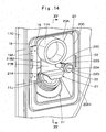
- a fuel filling door 19 that will be described later is shown by a virtual line as it is transparent in Fig, 7 , Fig, 8 , Figs. 10 to 14 , Figs. 18 to 20 , Fig. 22 for the convenience of description.
- a small-sized hydraulic excavator 1 which is a typical example of the small-sized construction machine includes a self-propelled crawler type lower traveling structure 2 and an upper revolving structure 4 rotatably mounted on the lower traveling structure 2 through a revolving device 3.
- a swing-type working mechanism 5 capable of swing in a left-right direction is provided on the front-part side of the upper revolving structure 4 and an excavating work of earth and sand or the like is performed by using this working mechanism 5.
- the small-sized hydraulic excavator 1 is used in a disassembling work inside a building, an excavating work in a narrow space such as a narrow street and thus, a machine weight is kept to approximately 0.8 to 8 tons, for example.
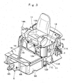
- the upper revolving structure 4 is constituted by including a revolving frame 6 which will be described later, an engine 7, a counterweight 9, a support member 10, a fuel tank 11, an operator's seat platform 13, an operator's seat 14, and a cab 17.
- the small-sized hydraulic excavator 1 is applied to a small work site such as an inside of a building, a street or the like, for example, the upper revolving structure 4 is formed small.
- a space for disposing various onboard devices on the revolving frame 6 is small, and the operator's seat 14 is disposed on an upper side of the fuel tank 11.
- the revolving frame 6 is rotatably provided on the lower traveling structure 2 through the revolving device 3 and configures a base of the upper revolving structure 4.
- the revolving frame 6 is formed of a support structural body by including a bottom plate 6A formed using a thick steel plate or the like and having a rectangular shape extending in a front-and-rear direction and a left vertical plate 6B and a right vertical plate 6C provided upright on the bottom plate 6A so as to extend in the front-and-rear direction.
- a support bracket 6D is provided on front end portions of the left and right vertical plates 6B and 6C.
- the support bracket 6D supports a swing post 5A provided on a base end of the working mechanism 5, capable of swing in the left-and-right direction.
- the engine 7 as a prime mover is located on the front side of the counterweight 9 which will be described later and mounted on the rear side of the revolving frame 6.
- the engine 7 is disposed on the revolving frame 6 in a laterally placed state with a crank shaft (not shown) extending in the left-and-right direction.
- a hydraulic pump 8 is provided on a left side of the engine 7.
- the hydraulic pump 8 supplies a pressurized oil toward various hydraulic actuators mounted on the hydraulic excavator 1 by being driven by the engine 7.
- heat exchangers such as a radiator, an oil cooler and the like (none of them is shown) are disposed on a right side of the engine 7.
- the counterweight 9 is provided on a rear side of the revolving frame 6.
- the counterweight 9 is to take a weight balance with the working mechanism 5 and is formed as an arc-shaped heavy article with a middle part in the left-and-right direction protruding rearward.
- the support member 10 is disposed on the left side of the revolving frame 6 and is mounted on the revolving frame 6 so as to be provided across the engine 7.
- the support member 10 has the operator's seat platform 13 which will be described later mounted and is to support the rear side of the cab 17.
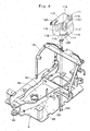
- the fuel tank 11 is mounted on the bottom plate 6A by being located closer to the left side than the left vertical plate 6B of the revolving frame 6 and being located on a middle part of the bottom plate 6A in the left-and-right direction. As shown in Fig. 5 , the fuel tank 11 is disposed in the cab 17 near the left surface part 17C. In this case, the fuel tank 11 is disposed so as to fit in a space between a left lower surface of the operator's seat platform 13 that will be described later and the bottom plate 6A. The fuel tank 11 is to store the fuel to be supplied to the engine 7.
- the fuel tank 11 is formed as a box-shaped body surrounded by an top surface 11A, a bottom surface 11B, a front surface 11C, a rear surface 11D, a left surface 11E, and a right surface 11F.
- a front surface recessed part 11G is formed at a corner part where the front surface 11C and the left surface 11E cross each other and is dented toward the rear surface 11D side over the entire region in the up-and-down direction.
- a side surface recessed part 11H dented to the right surface 11F side is formed at a corner part where an upper-side portion of the left surface 11E and the front surface recessed part 11G cross each other.
- the fuel tank 11 is not an even cuboid body but is formed having a complicated three-dimensional shape having the front surface recessed part 11G, the side surface recessed part 11H and the like such as to ensure as large capacity as possible while avoiding interference with various onboard devices mounted on the revolving frame 6.
- a cylindrical fuel filling port 11J is provided on an outer surface of a corner part where the top surface 11A, the rear surface 11D, and the left surface 11E of the fuel tank 11 cross each other.
- the fuel filling port 11J is a port into which a fuel supply nozzle (not shown) is inserted when the fuel is supplied to the fuel tank 11.
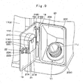
- the fuel filling port 11J protrudes upward diagonally left from the outer surface of the fuel tank 11 and a protruding end of the fuel filling port 11J is disposed in a fuel filling opening 18 which will be described later of the cab 17 (see Fig. 9 and Fig.15 ).
- the fuel filling port 11J is provided on the rear side of a door 17C2 of the cab 17, facing the fuel filling opening 18.
- the fuel filling port 11J is closed with a cap 11K.
- the top surface 11A side of the fuel tank 11 is fixed to the operator's seat platform 13 by using a mounting bracket 12A and bolts (not shown) and the bottom surface 11B side of the fuel tank 11 is fixed to the bottom plate 6A by using a mounting bracket 12B and bolts 12C.
- the fuel tank 11 is located on the left side of the left vertical plate 6B of the revolving frame 6 and on middle part of the bottom plate 6A in a front-rear-direction and is attached onto the bottom plate 6A.
- the fuel tank 11 brought closer to the left surface part 17C side of the cab 17 that will be described later and is disposed between the revolving frame 6 and the operator's seat platform 13.
- the operator's seat platform 13 is provided on the revolving frame 6 through the support member 10 in a state where the upper side of the fuel tank 11 is covered.
- This operator's seat platform 13 is formed into a substantially cubic shape and is adapted to mount the operator's seat 14 that will be described later.
- the operator's seat 14 is mounted on the operator's seat platform 13 mounted on the revolving frame 6.
- the operator's seat 14 is for the operator who operates the small-sized hydraulic excavator 1 to be seated, and an operation device 14A for operating the revolving device 3, the working mechanism 5 and the like is disposed on both left and right sides of the operator's seat 14.
- a floor member 15 is provided on a front side of the operator's seat platform 13.
- the floor member 15 is for forming a footing for the operator who gets onboard the small-sized hydraulic excavator 1.
- a space for accommodating the onboard devices (not shown) such as a control valve or the like is formed between the bottom plate 6A of the revolving frame 6 and the floor member 20.
- two left and right traveling lever pedals 21 to control a traveling operation of the lower traveling structure 2 are provided on the front side of the floor member 20.
- the cab 17 is formed as a box body surrounding a periphery of the operator's seat 18 and defines the operator's chamber. As shown in Fig. 5 , the cab 17 is formed into formed having a box shape surrounded by a front surface part 17A, a rear surface part 17B that faces the front surface part 17A in the front-rear direction, the left surface part 17C and a right surface part (not shown) that faced in the left-right direction sandwiching the front surface part 17A and the rear surface part 17B and a top surface part 17D closes top ends of the front surface part 17A, the rear surface part 17B, the left surface part 17C and the right surface part.
- the left surface part 17C of the cab 17 is constituted by an entrance way 17C1, a door 17C2 with window for opening/closing the entrance way 17C1, and a left rear window 17C3 located on a rear side of the door 17C2. It is constituted such that the operator gets on/off the cab 17 through the entrance way 17C1 by opening the door 17C2.
- the cab 17 is mounted onto the revolving frame 6 by its rear side supported by the support member 10 and its front side supported by a support plate on the revolving frame 6 . Thereby, the operator's seat 14, the operation device 14A, the traveling levers/pedals 16 and the like are accommodated in the cab 17 and the fuel tank 11 is disposed by bringing closer to the left surface part 17C side of the cab 17. In addition, an upper part of the engine 7 is covered with the cab 17 (see Fig.1 ).
- the fuel filling opening 18 is provided in the left surface part 17C of the cab 17 at a position where it faces the fuel filling port 11J of the fuel tank 11. That is, as shown in Fig. 5 , the fuel filling opening 18 is formed as a rectangular hole at a position behind the door 17C2 of the left surface part 17C and under the left rear window 17C3. Accordingly, the fuel filling opening 18 of the left surface part 17C is disposed at a position where it surrounds the fuel filling port 11J of the fuel tank 11 in a state of mounting the cab 17 on the revolving frame 6.
- the fuel filling port 11J of the fuel tank 11 can be exposed to an outside through the fuel filling opening 18, and a fuel filling work can be performed by inserting a fuel supply nozzle from outside of the cab 17 into the fuel filling port 11J of the fuel tank 11.
- the fuel filling door 19 is provided on the left surface part 17C of the cab 17 at a position corresponding to that of the fuel filling opening 18.
- This fuel filling door 19 is formed into a rectangular shape corresponding the fuel filling opening 18 by using a metal plate as a lid member that caps the fuel filling opening 18 capable of being opened/closed.
- the front side of the fuel filling door 19 is fixed to the left surface part 17C through a hinge 19A and the fuel filling door 19 is opened/closed in a single-swinging manner with the hinge 19A being set as a fulcrum.
- a scattering preventing cover 20 is provided between the fuel filling port 11J of the fuel tank 11 and the fuel filling opening 18 formed in the left surface part 17C of the cab 17.
- the scattering preventing cover 20 is, when the fuel is spilled from the fuel filling port 11J during the fuel filling work to the fuel tank 11, to suppress scattering of this spilled fuel to the periphery of the fuel tank 11.
- the scattering preventing cover 20 is formed by using, for example, an elastic resinous material and has a pyramid-shaped cylindrical part 20A expanded from the fuel tank 11 toward the left surface part 17C of the cab 17.
- a circular tank side opening 20B that surrounds the fuel filling port 11J of the fuel tank 11 is opened in a part that corresponds to the fuel tank 11 in the cylindrical part 20A.
- a part that is located on the opposite side (the left surface part 17C side of the cab 17) to the tank side opening 20B is formed as a quadrilateral cab side opening 20C that surrounds the fuel filling opening 18 of the cab 17.
- the scattering preventing cover 20 makes the tank side opening 20B insert and fit into the fuel filling port 11J of the fuel tank 11 and makes the cab side opening 20C fit into the fuel filling opening 18 and fix to an inner circumferential edge thereof.
- the scattering preventing cover 20 is configured to be disposed between the fuel filling port 11J of the fuel tank 11 and the fuel filling opening 18 of the cab 17 so as to shield the fuel filling port 11J of the fuel tank 11 against the inside of the cab 17 (see Fig. 15 ).
- an outer circumferential edge part of the cab side opening 20C of the scattering preventing cover 20 is formed as a frame part 20A1 of the cylindrical part 20A.
- this frame part 20A1 surrounds the circumference of the fuel filling opening 18 and fits into the fuel filling opening 18 over the whole circumference of an inner circumferential edge thereof.
- the frame part 20A1 configures an abutting member on which this cap 11K abuts when the cap 11K that is held on a cap holder 21 that will be described later is pushed upward by a lock 22 that will be described later.
- the cap holder 21 is located on the inner surface side of the fuel filling door 19 and is provided at an substantially center position of the fuel filling door 19.
- This cap holder 21 is formed by a horizontal plate 21A and a vertical plate 21B as a plate body that is bent into a substantially L shape.
- a guide groove 21C is provided on the leading end side of the vertical plate 21B (the top end 21B1 side) so as to be located on a middle part in the left-right direction (a width direction). That is, the guide groove 21C is located on the top end 21B1 of the vertical plate 21B and is provided between a front end 21B2 and a rear end 21B3.
- This guide groove 21C is formed as a U-shaped notched groove that extends in the up-down direction from the top end 21B1 of the vertical plate 21B toward a lower end thereof and it is a groove into which a grip part 11K1 that constitutes part of the cap 11K is to be inserted. Specifically, the guide groove 21C is opened in a direction in which the cap 11K is able to move by being pushed by a lock lever 22C when the lock lever 22C that will be described later rotationally moves from an unlocked position to a locked position.
- the base end side of the horizontal plate 21A is fixedly attached to the inner surface side of the fuel filling door 19 by means such as welding and the like.
- a gap that is just as wide as a width dimension of the horizontal plate 21A is formed between the vertical plate 21B of the cap holder 21 and an inner surface of the fuel filling door 19.
- the lock 22 is located on the rear end side of the fuel filling door 19 (the side opposite to the hinge 19A) and is provided at an substantially center position in the up-down direction (a height direction) of the fuel filling door 19.
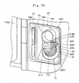
- This lock 22 is configured by a mounting member 22A that is provided by being fixed to the fuel filling door 19, a cylindrical rotating member 22B that is rotatably attached to the mounting member 22A, the lock lever 22C that is attached to the rotating member 22B, and a key hole 22D that is provided through the mounting member 22A and the rotating member 22B.
- the rotating member 22B is rotatably attached to the mounting member 22A on the base end side and projects from the inner surface side of the fuel filling door 19 toward the fuel tank 11 side on the leading end side.
- the lock lever 22C is attached to the rotating member 22B on the base end side and enters into a gap between an inner surface of the vertical plate 21B of the cap holder 21 and the inner surface of the fuel filling door 19 on the leading end side.
- the lock 22 is adapted to perform unlocking and locking of the fuel filling door 19 with the fuel filling opening 18 closed by inserting a key (not shown) into the key hole 22D so as to rotationally move the rotating member 22B and the lock lever 22C.
- the lock 22 rotationally moves between the locking position where the fuel filling door 19 maintains a state where the fuel filling opening 18 is closed and the unlocking position where the fuel filling door 19 allows opening of the fuel filling opening 18.
- the lock lever 22C is configured by a long member which base end side is fixed to the rotating member 22B and a lengthwise middle part is bent.
- the lock lever 22C rotationally moves (rotates) 180 degrees in a circumferential direction in linkage with the rotating member 22B.
- a leading end of the lock lever 22C is inserted into a lever insertion hole 23 provided in a side surface of the fuel filling opening 18 and the fuel filling door 19 maintains the state where the fuel filling opening 18 is closed (see Fig. 7 , Fig. 8 ).
- the small-sized hydraulic excavator 1 has the constitution as above and subsequently, an operation of the hydraulic excavator 1 will be described.
- the small-sized hydraulic excavator 1 having a machine weight of approximately 0.8 to 8 tons is transported to a work site in a state loaded on a bed of a truck.
- the operator opens the door 17C2 of the cab 17, gets on the cab 17 through the entrance way 17C1 and seats on the operator's seat 14 disposed on the cab 17.
- the operator seated on the operator's seat 14 operates the engine 7 and then, operates the left and right traveling lever pedals 16 disposed on the front side of the operator's seat 14.
- the hydraulic excavator 1 is self-propelled to a desired work site by the lower traveling structure 2.
- the operator After the small-sized hydraulic excavator 1 has been self-propelled to the desired work site, the operator operates the operation device 14A provided on the both sides of the operator's seat 14. As a result, the hydraulic excavator 1 can perform the disassembling work inside the building, a ditch excavating work in a narrow street or the like, an excavating work of earth and sand and the like by using the working mechanism 5, while the upper revolving structure 4 is revolved on the lower traveling structure 2.
- the lock 22 is rotationally moved from the locked position to the unlocked position and opens the fuel filling door 19.
- the fuel filling port 11J of the fuel tank 11 is exposed to the outside through the fuel filling opening 18 (see Fig. 6 ).
- the cap 11K is removed from the fuel filling port 11J of the fuel tank 11 that is disposed in the fuel filling opening 18 and the fuel is filled in a state of inserting the fuel supplying nozzle into the fuel filling port 11J.
- the grip part 11K1 of the removed cap 11K is inserted into the guide groove 21C in the cap holder 21. Therefore, the cap 11K is held in the gap between the vertical plate 21B of the cap holder 21 and the inner surface of the fuel filling door 19 (see Fig. 9 ). Thereby, it is possible to eliminate possibilities of missing of the cap 11K caused by letting it fall into the hydraulic excavator 1 and of staining thereof caused by letting it fall to the ground.
- the cap 11K is removed from the cap holder 21 to close the fuel filling port 11J of the fuel tank 11. Then, as shown in Fig. 7 and Fig.8 , the fuel filling door 19 is locked from the outside by rotationally moving the lock 22 toward a lever insertion hole 23 in the circumferential direction in a state where the fuel filling door 19 closes the fuel filling opening 18.
- the lock 22 does not rotationally move toward the locking position anymore and locking of the fuel filling door 19 becomes impossible.
- the lock 22 cannot be locked. Accordingly, omission of closing the cap 11K is noticed and thus it is possible to prevent omission of closing the cap 11K relative to the fuel filling port 11J. Consequently, it is possible to confirm to cap the fuel filling port 11J of the fuel tank 11 with the cap 11K.
- the cap holder 21 attached to the inner surface side of the fuel filling door 19 and the lock 22 that locks the fuel filling door 19 from the outside are provided on the fuel filling door 19.
- This lock 22 has the lock lever 22C that rotationally moves between the locking position where the fuel filling door 19 maintains the state where the fuel filling opening 18 is closed and the unlocking position where the fuel filling door 19 allows opening of the fuel filling opening 18. Then, in the lock lever 22C, the base end is rotatably attached to the fuel filling door 19 and the leading end is able to enter the gap between the fuel filling door 19 and the cap holder 21.
- the lock lever 22C of the lock 22 between the horizontal plate 21A of the cap holder 21 and the cap 11K. Accordingly, in a case where the fuel filling door 19 has been closed with the cap 11K being held on the cap holder 21, the lock 22 does not rotationally move to the locking position and therefore the fuel filling door 19 cannot be closed. That is, in a case of rotationally moving the lock 22 to be locked, the leading end part of the lock lever 22C acts to move the cap 11K upward and thereby the top end of the cap 11K abuts on the top end of the frame part 20A1 of the scattering preventing cover 20.
- the U-shaped guide groove 21C into which the grip part 11K1 of the cap 11K enters is provided in the top end 21B1 of the cap holder 21.
- the cap 11K that is held on the cap holder 21 is able to move along the guide groove 21C by being pushed by the lock lever 22C that rotationally moves from the unlocking position to the locking position. Consequently, since the guide groove 21C in the cap holder 21 allows the cap 11K to move upward while guiding it, it is possible to bring the cap 11K to abut on the top end of the frame part 20A1 of the scattering preventing cover 20.
- the fuel tank 11 is disposed on the lower side of the operator's seat platform 13 in the cab 17 and on the rear side of the door 17C2.
- the fuel filling opening 18 is provided on the rear side of the door 17C2 of the cab 17, facing the fuel filling port 11J of the fuel tank 11.
- the frame part 20A1 acting as the abutting member on which the cap 11K pushed by the lock lever 22C abuts when rotationally moving the lock lever 22C from the unlocking position to the locking position in a state of holding the cap 11K on the cap holder 21 is provided on the fuel filling opening 18.
- the scattering preventing cover 20 which prevents the filled fuel from scattering around is provided between the fuel filling opening 18 and the fuel filling port 11J of the fuel tank 11.
- the scattering preventing cover 20 shields the fuel filling port 11J of the fuel tank 11 from the inside of the cab 17 by inserting/fitting the tank-side opening 20B in the fuel filling port 11J of the fuel tank 11, and fitting the cab-side opening 20C over the entire circumference on the inner peripheral edge of the fuel filling opening 18.
- this spilled fuel can be shielded by the scattering preventing cover 20 from the inside of the cab 17.
- adhesion of the spilled fuel to the engine 7 whose temperature has become high or scattering of the same into the cab 17 and causing an odor can be suppressed, and a work environment can be kept favorable.
- the frame part 20A1 that surrounds the circumference of the fuel filling opening 18 is configured so as to also serve as the abutting member that abuts with the cap 11K.
- the lock lever 22C of the lock 22 is configured to perform unlocking and locking by rotating 180 degrees in the circumferential direction.
- the lock lever 22C is rotationally moved from the unlocking position to the locking position in a state of holding the cap 11K on the cap holder 21, it is possible to move the cap 11K upward by the lock lever 22C. Consequently, it is possible to bring the cap 11K into abutment on the frame part 20A1 of the scattering preventing cover 20 and to make locking of the fuel filling door 19 impossible.
- omission of closing the cap 11K is noticed and thus it is possible to prevent omission of closing the cap 11K relative to the fuel filling port 11J.
- the configuration that the guide groove 21C in the cap holder 21 is formed as the U-shaped notched groove that extends in the up-down direction from the top end 21B1 to the lower end of the vertical plate 21B is made in the aforementioned embodiment.
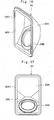
- the present invention is not limited to this and may be also configured as in, for example, a first modified example shown in Fig. 18 and Fig. 19 . That is, a guide groove 31B in a cap holder 31 is not formed in a top end 31A1 of a vertical plate 31A and is formed as a U-shaped notched groove that diagonally extends from the front end 31A2 side toward the rear end 31A3 side of the vertical plate 31A as shown in Fig. 18 .
- a configuration that a lock 32 is provided on a rear-side top end of the fuel filling door 19 may be also made.
- a lock lever 32A acts to move the cap 11K toward the front side (the hinge 19A side) along the guide groove 31B.
- the lock lever 22C acts to move the cap 11K upward along the guide groove 21C and the top end of the cap 11K abuts on the top end of the frame part 20A1 of the scattering preventing cover 20.
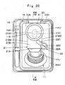
- the present invention is not limited to this and may be also configured as in, for example, a second modified example shown in Fig. 20 and Fig. 21 .
- a sheet metal member 41 made of a metal as an abutting member may be constituted so as to fixedly attached to the top end of the fuel filling opening 18 by means such as welding and the like.
- the guide groove 21C in the cap holder 21 is formed as the U-shaped notched groove that extends in the up-down direction from the top end 21B1 toward the lower end of the vertical plate 21B.
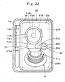
- the present invention is not limited to this and may be configured as in, for example, a third modified example shown in Fig. 22 . That is, it may be constituted such that a guide groove 51B in a cap holder 51 is formed as an inverted L-shaped notched groove that is bent substantially at right angles from a top end 51A1 of a vertical plate 51A and extends toward the front end 51A2 side.
- the grip part 11K1 of the cap 11K is held on a holder part 51B1 acting as a closing end of the guide groove 51B in a state of holding the cap 11K on the cap holder 51.
- movement of the cap 11K in the up-down direction is restricted. Accordingly, in a case where locking is performed by rotationally moving the lock 22, since rotational movement of the lock 22 toward the locking position is restricted by abutment of the lock lever 22C on the cap 11K, the fuel filling door 19 cannot be locked.
- the present invention is not limited to this and it may be configured that, for example, the scattering preventing cover and the frame part formed as separate members.
- the small-sized hydraulic excavator 1 including the crawler-type lower traveling structure 2 is described as an example, but the present invention is not limited to that and may be applied to a small-sized hydraulic excavator including a wheel-type lower traveling structure, for example.
Landscapes
- Engineering & Computer Science (AREA)
- Mechanical Engineering (AREA)
- Mining & Mineral Resources (AREA)
- Civil Engineering (AREA)
- General Engineering & Computer Science (AREA)
- Structural Engineering (AREA)
- Sustainable Development (AREA)
- Sustainable Energy (AREA)
- Chemical & Material Sciences (AREA)
- Combustion & Propulsion (AREA)
- Transportation (AREA)
- Life Sciences & Earth Sciences (AREA)
- Lock And Its Accessories (AREA)
- Cooling, Air Intake And Gas Exhaust, And Fuel Tank Arrangements In Propulsion Units (AREA)
- Component Parts Of Construction Machinery (AREA)
Claims (6)
- Kleine Baumaschine (1), umfassend:einen selbstangetriebenen unteren Fahraufbau (2);einen oberen Drehaufbau (4), der drehbar an dem unteren Fahraufbau (2) montiert ist; undeinen Arbeitsmechanismus (5), der an der Vorderteilseite des oberen Drehaufbaus (4) vorgesehen ist, wobei der obere Drehaufbau (4) umfasst:einen Drehrahmen (6), der einen Trägerbaukörper bildet,ein Gegengewicht (9), das an einer Rückseite des Drehrahmens (6) vorgesehen ist,einen Motor (7), der an der Vorderseite des Gegengewichts (9) angeordnet und an dem Drehrahmen (6) montiert ist,eine Kabine (17), die an dem Drehrahmen (6) vorgesehen ist, um so den Motor (7) von oben und an einer Seite in einer Links-Rechts-Richtung, an der eine öffenbare/schließbare Tür (17C2) vorgesehen ist, zu bedecken, undeinen Kraftstofftank (11), der einen Kraftstofffülldurchlass (11J) und eine Kappe (11K) aufweist, die den Kraftstofffülldurchlass (11 J) schließt und Kraftstoff zur Lieferung an dem Motor (7) speichert, wobeieine Kraftstofffüllöffnung (18), die an der Seite hinter der Tür (17C2) angeordnet ist und den Kraftstofffülldurchlass (11J) des Kraftstofftanks (11) umgibt, und ein Deckelelement (19), das die Kraftstofffüllöffnung (18) verschließt, so dass sie öffenbar/schließbar ist, an einer Außenfläche an einer Seite in der Links-Rechts-Richtung vorgesehen sind, an der die Tür (17C2) der Kabine (17) vorgesehen ist, dadurch gekennzeichnet, dass:ein Kappenhalter (21, 31, 51), der an der Innenflächenseite des Deckelelements (19) befestigt ist, in einem Zustand, in dem er zu einer Innenfläche des Deckelelements (19) mit einem Intervall weist, um die Kappe (11K) von dem Kraftstofftank (11) entfernt zu halten, und eine Verriegelung (22, 32), die das Deckelelement (19) von der Außenseite in einem Zustand verriegelt, in dem das Deckelelement (19) die Kraftstofffüllöffnung (18) schließt, an dem Deckelelement (19) vorgesehen sind,die Verriegelung (22, 32) einen Verriegelungshebel (22C, 32A) aufweist, der aus einem langen Element, einem Basisende, das drehbar an dem Deckelelement (19) befestigt ist, und einem vorauslaufenden Ende zusammengesetzt ist, das in den Spalt zwischen dem Deckelelement (19) und dem Kappenhalter (21, 31, 51) eintreten kann, und das sich drehbar zwischen einer Verriegelungsposition, in der das Deckelelement (19) einen Zustand zum Schließen der Kraftstofffüllöffnung (18) beibehält, und einer Entriegelungsposition bewegt, in dem das Deckelelement (19) ein Öffnen der Kraftstofffüllöffnung (18) zulässt.
- Kleine Baumaschine (1) nach Anspruch 1, wobeieine U-förmige Führungsnut, in die ein Teil der Kappe (11K) eintritt, in dem Kappenhalter (21, 31, 51) vorgesehen ist, unddie Führungsnut in dem Kappenhalter (21, 31, 51) sich in einer Richtung öffnet, in der die Kappe (11K) sich durch Drücken durch den Verriegelungshebel (22C, 32A) bewegen kann, wenn der Verriegelungshebel (22C, 32A) sich drehend von der Entriegelungsposition in die Verriegelungsposition bewegt hat.
- Kleine Baumaschine (1) nach Anspruch 1, wobei
der Kraftstofffülldurchlass (11J) des Kraftstofftanks (11) an der Rückseite der Tür (17C2) der Kabine (17) vorgesehen ist, der zu der Kraftstofffüllöffnung (18) weist, die an der Kabine (17) vorgesehen ist. - Kleine Baumaschine (1) nach Anspruch 2, wobei
die Kraftstofffüllöffnung (18) so konfiguriert ist, dass sie mit einem Anschlagelement ausgestattet ist, an dem die Kappe (11K), die von dem Verriegelungshebel (22C, 32A) gedrückt wird, anliegt, wenn der Verriegelungshebel (22C, 32A) drehend von der Entriegelungsposition in die Verriegelungsposition in einem Zustand bewegt wird, wenn die Kappe (11K) an dem Kappenhalter (21, 31, 51) gehalten ist. - Kleine Baumaschine (1) nach Anspruch 4, wobeieine Spritzschutzabdeckung (20), die verhindert, dass einzufüllender Kraftstoff verspritzt wird, zwischen der Kraftstofffüllöffnung (18) und dem Kraftstofffülldurchlass (11J) des Kraftstofftanks (11) vorgesehen ist, undein Rahmenteil (20A1), das den Umfang der Kraftstofffüllöffnung (18) umgibt, so konfiguriert ist, dass es auch als das Anschlagelement in der Spritzschutzabdeckung (20) dient.
- Kleine Baumaschine nach Anspruch 1, wobei
der Verriegelungshebel (22C, 32A) der Verriegelung (22, 32) ein Entriegeln und Verriegeln durch Drehung um 180 Grad in einer Umfangsrichtung ausführt.
Applications Claiming Priority (2)
| Application Number | Priority Date | Filing Date | Title |
|---|---|---|---|
| JP2015255487A JP6487317B2 (ja) | 2015-12-26 | 2015-12-26 | 小型の建設機械 |
| PCT/JP2016/076313 WO2017110158A1 (ja) | 2015-12-26 | 2016-09-07 | 小型の建設機械 |
Publications (3)
| Publication Number | Publication Date |
|---|---|
| EP3396071A1 EP3396071A1 (de) | 2018-10-31 |
| EP3396071A4 EP3396071A4 (de) | 2019-09-18 |
| EP3396071B1 true EP3396071B1 (de) | 2020-07-29 |
Family
ID=59089985
Family Applications (1)
| Application Number | Title | Priority Date | Filing Date |
|---|---|---|---|
| EP16878055.9A Active EP3396071B1 (de) | 2015-12-26 | 2016-09-07 | Kompakte baumaschine |
Country Status (6)
| Country | Link |
|---|---|
| US (1) | US10458160B2 (de) |
| EP (1) | EP3396071B1 (de) |
| JP (1) | JP6487317B2 (de) |
| KR (1) | KR102078235B1 (de) |
| CN (1) | CN108138463B (de) |
| WO (1) | WO2017110158A1 (de) |
Families Citing this family (7)
| Publication number | Priority date | Publication date | Assignee | Title |
|---|---|---|---|---|
| CN107527410B (zh) * | 2017-08-22 | 2019-10-11 | 永康市陌桐电子科技有限公司 | 一种智能化车辆解封方法 |
| CN107341894B (zh) * | 2017-08-22 | 2019-09-24 | 济宁职业技术学院 | 智能化车辆解封系统 |
| CN109577410B (zh) * | 2018-12-12 | 2021-04-20 | 恒天九五重工有限公司 | 一种挖掘机用锁紧机构 |
| JP6964612B2 (ja) * | 2019-01-25 | 2021-11-10 | 日立建機株式会社 | 建設機械 |
| US11155157B2 (en) * | 2019-03-25 | 2021-10-26 | Cnh Industrial America Llc | Locking system for a fuel compartment assembly of a work vehicle |
| JP7721587B2 (ja) * | 2023-02-27 | 2025-08-12 | 株式会社竹内製作所 | 作業用車両 |
| JP2025006873A (ja) * | 2023-06-30 | 2025-01-17 | 株式会社クボタ | 作業機 |
Family Cites Families (13)
| Publication number | Priority date | Publication date | Assignee | Title |
|---|---|---|---|---|
| US4746089A (en) * | 1987-03-23 | 1988-05-24 | Earl Clapper | Magnetic fuel tank cap holding system |
| WO1991004885A1 (en) * | 1989-09-27 | 1991-04-18 | Harrison Terry W | Automobile fuel tank fuel cap holder |
| JPH0446823A (ja) * | 1990-06-12 | 1992-02-17 | Toyota Autom Loom Works Ltd | 自動車のフューエルリッド構造 |
| US5580019A (en) * | 1995-05-17 | 1996-12-03 | Glesser; Louis S. | Retrofitable gas cap holders |
| JP3299138B2 (ja) * | 1997-03-24 | 2002-07-08 | 新キャタピラー三菱株式会社 | 建設機械 |
| KR19990027954U (ko) * | 1997-12-24 | 1999-07-15 | 양재신 | 자동차용 연료 캡 걸이 |
| JP2003211983A (ja) * | 2002-01-22 | 2003-07-30 | Hitachi Constr Mach Co Ltd | 建設機械 |
| JP2004299414A (ja) * | 2003-03-28 | 2004-10-28 | Kobelco Contstruction Machinery Ltd | 建設機械 |
| JP2005104284A (ja) * | 2003-09-30 | 2005-04-21 | Japan Steel:Kk | 燃料タンクの蓋におけるキャップ忘れ防止ハンガー |
| JP2006111073A (ja) * | 2004-10-13 | 2006-04-27 | Nissan Motor Co Ltd | 車両のフューエルリッド構造 |
| JP5009727B2 (ja) * | 2007-09-04 | 2012-08-22 | ヤック株式会社 | 給油キャップホルダー |
| DE202013001917U1 (de) * | 2013-02-27 | 2013-03-13 | GM Global Technology Operations LLC (n. d. Ges. d. Staates Delaware) | Verriegelungsanordnung für eine Kraftfahrzeugklappe |
| CN204472558U (zh) * | 2015-02-10 | 2015-07-15 | 柳州日高过滤器有限责任公司 | 工程车辆塑料燃油箱盖进气阀结构 |
-
2015
- 2015-12-26 JP JP2015255487A patent/JP6487317B2/ja active Active
-
2016
- 2016-09-07 EP EP16878055.9A patent/EP3396071B1/de active Active
- 2016-09-07 KR KR1020187006359A patent/KR102078235B1/ko active Active
- 2016-09-07 WO PCT/JP2016/076313 patent/WO2017110158A1/ja not_active Ceased
- 2016-09-07 CN CN201680051239.9A patent/CN108138463B/zh active Active
- 2016-09-07 US US15/757,504 patent/US10458160B2/en active Active
Non-Patent Citations (1)
| Title |
|---|
| None * |
Also Published As
| Publication number | Publication date |
|---|---|
| US10458160B2 (en) | 2019-10-29 |
| EP3396071A4 (de) | 2019-09-18 |
| US20180245381A1 (en) | 2018-08-30 |
| KR20180037033A (ko) | 2018-04-10 |
| JP6487317B2 (ja) | 2019-03-20 |
| CN108138463B (zh) | 2020-06-12 |
| KR102078235B1 (ko) | 2020-02-17 |
| EP3396071A1 (de) | 2018-10-31 |
| JP2017115558A (ja) | 2017-06-29 |
| WO2017110158A1 (ja) | 2017-06-29 |
| CN108138463A (zh) | 2018-06-08 |
Similar Documents
| Publication | Publication Date | Title |
|---|---|---|
| US10458160B2 (en) | Small-sized construction machine | |
| US10961689B2 (en) | Small-sized construction machine with heat exchanger cover | |
| US11499288B2 (en) | Hydraulic excavator | |
| EP3680396B1 (de) | Baumaschine | |
| KR20170066275A (ko) | 작업 차량 | |
| EP3351909B1 (de) | Kompakte baumaschine | |
| JP5579678B2 (ja) | 建設機械 | |
| JP7339454B2 (ja) | 建設機械 | |
| JP5785128B2 (ja) | 旋回作業機の運転部におけるマニュアル収納部構造 | |
| JP4908392B2 (ja) | 建設機械 | |
| US9121161B2 (en) | Construction machine | |
| JP6932675B2 (ja) | 転圧機械 | |
| JP7846217B2 (ja) | 作業車両 | |
| CN105887961B (zh) | 挖土机 | |
| JP5124503B2 (ja) | 旋回作業機のカバー装置 | |
| JP2025147920A (ja) | 作業機械 | |
| JP2025029617A (ja) | 作業用車両 | |
| US20220112679A1 (en) | Construction Machine | |
| JP2005163533A (ja) | 作業機械 | |
| WO2016208220A1 (ja) | 小型油圧ショベル |
Legal Events
| Date | Code | Title | Description |
|---|---|---|---|
| STAA | Information on the status of an ep patent application or granted ep patent |
Free format text: STATUS: THE INTERNATIONAL PUBLICATION HAS BEEN MADE |
|
| PUAI | Public reference made under article 153(3) epc to a published international application that has entered the european phase |
Free format text: ORIGINAL CODE: 0009012 |
|
| STAA | Information on the status of an ep patent application or granted ep patent |
Free format text: STATUS: REQUEST FOR EXAMINATION WAS MADE |
|
| 17P | Request for examination filed |
Effective date: 20180326 |
|
| AK | Designated contracting states |
Kind code of ref document: A1 Designated state(s): AL AT BE BG CH CY CZ DE DK EE ES FI FR GB GR HR HU IE IS IT LI LT LU LV MC MK MT NL NO PL PT RO RS SE SI SK SM TR |
|
| AX | Request for extension of the european patent |
Extension state: BA ME |
|
| DAV | Request for validation of the european patent (deleted) | ||
| DAX | Request for extension of the european patent (deleted) | ||
| A4 | Supplementary search report drawn up and despatched |
Effective date: 20190816 |
|
| RIC1 | Information provided on ipc code assigned before grant |
Ipc: B60K 15/05 20060101ALI20190809BHEP Ipc: E05B 83/34 20140101ALI20190809BHEP Ipc: E02F 9/00 20060101AFI20190809BHEP |
|
| GRAP | Despatch of communication of intention to grant a patent |
Free format text: ORIGINAL CODE: EPIDOSNIGR1 |
|
| STAA | Information on the status of an ep patent application or granted ep patent |
Free format text: STATUS: GRANT OF PATENT IS INTENDED |
|
| INTG | Intention to grant announced |
Effective date: 20200211 |
|
| GRAS | Grant fee paid |
Free format text: ORIGINAL CODE: EPIDOSNIGR3 |
|
| GRAA | (expected) grant |
Free format text: ORIGINAL CODE: 0009210 |
|
| STAA | Information on the status of an ep patent application or granted ep patent |
Free format text: STATUS: THE PATENT HAS BEEN GRANTED |
|
| AK | Designated contracting states |
Kind code of ref document: B1 Designated state(s): AL AT BE BG CH CY CZ DE DK EE ES FI FR GB GR HR HU IE IS IT LI LT LU LV MC MK MT NL NO PL PT RO RS SE SI SK SM TR |
|
| REG | Reference to a national code |
Ref country code: CH Ref legal event code: EP |
|
| REG | Reference to a national code |
Ref country code: AT Ref legal event code: REF Ref document number: 1295941 Country of ref document: AT Kind code of ref document: T Effective date: 20200815 |
|
| REG | Reference to a national code |
Ref country code: IE Ref legal event code: FG4D |
|
| REG | Reference to a national code |
Ref country code: DE Ref legal event code: R096 Ref document number: 602016041083 Country of ref document: DE |
|
| REG | Reference to a national code |
Ref country code: LT Ref legal event code: MG4D |
|
| REG | Reference to a national code |
Ref country code: NL Ref legal event code: MP Effective date: 20200729 |
|
| REG | Reference to a national code |
Ref country code: AT Ref legal event code: MK05 Ref document number: 1295941 Country of ref document: AT Kind code of ref document: T Effective date: 20200729 |
|
| PG25 | Lapsed in a contracting state [announced via postgrant information from national office to epo] |
Ref country code: FI Free format text: LAPSE BECAUSE OF FAILURE TO SUBMIT A TRANSLATION OF THE DESCRIPTION OR TO PAY THE FEE WITHIN THE PRESCRIBED TIME-LIMIT Effective date: 20200729 Ref country code: GR Free format text: LAPSE BECAUSE OF FAILURE TO SUBMIT A TRANSLATION OF THE DESCRIPTION OR TO PAY THE FEE WITHIN THE PRESCRIBED TIME-LIMIT Effective date: 20201030 Ref country code: HR Free format text: LAPSE BECAUSE OF FAILURE TO SUBMIT A TRANSLATION OF THE DESCRIPTION OR TO PAY THE FEE WITHIN THE PRESCRIBED TIME-LIMIT Effective date: 20200729 Ref country code: PT Free format text: LAPSE BECAUSE OF FAILURE TO SUBMIT A TRANSLATION OF THE DESCRIPTION OR TO PAY THE FEE WITHIN THE PRESCRIBED TIME-LIMIT Effective date: 20201130 Ref country code: SE Free format text: LAPSE BECAUSE OF FAILURE TO SUBMIT A TRANSLATION OF THE DESCRIPTION OR TO PAY THE FEE WITHIN THE PRESCRIBED TIME-LIMIT Effective date: 20200729 Ref country code: NO Free format text: LAPSE BECAUSE OF FAILURE TO SUBMIT A TRANSLATION OF THE DESCRIPTION OR TO PAY THE FEE WITHIN THE PRESCRIBED TIME-LIMIT Effective date: 20201029 Ref country code: ES Free format text: LAPSE BECAUSE OF FAILURE TO SUBMIT A TRANSLATION OF THE DESCRIPTION OR TO PAY THE FEE WITHIN THE PRESCRIBED TIME-LIMIT Effective date: 20200729 Ref country code: AT Free format text: LAPSE BECAUSE OF FAILURE TO SUBMIT A TRANSLATION OF THE DESCRIPTION OR TO PAY THE FEE WITHIN THE PRESCRIBED TIME-LIMIT Effective date: 20200729 Ref country code: LT Free format text: LAPSE BECAUSE OF FAILURE TO SUBMIT A TRANSLATION OF THE DESCRIPTION OR TO PAY THE FEE WITHIN THE PRESCRIBED TIME-LIMIT Effective date: 20200729 Ref country code: BG Free format text: LAPSE BECAUSE OF FAILURE TO SUBMIT A TRANSLATION OF THE DESCRIPTION OR TO PAY THE FEE WITHIN THE PRESCRIBED TIME-LIMIT Effective date: 20201029 |
|
| PG25 | Lapsed in a contracting state [announced via postgrant information from national office to epo] |
Ref country code: PL Free format text: LAPSE BECAUSE OF FAILURE TO SUBMIT A TRANSLATION OF THE DESCRIPTION OR TO PAY THE FEE WITHIN THE PRESCRIBED TIME-LIMIT Effective date: 20200729 Ref country code: RS Free format text: LAPSE BECAUSE OF FAILURE TO SUBMIT A TRANSLATION OF THE DESCRIPTION OR TO PAY THE FEE WITHIN THE PRESCRIBED TIME-LIMIT Effective date: 20200729 Ref country code: LV Free format text: LAPSE BECAUSE OF FAILURE TO SUBMIT A TRANSLATION OF THE DESCRIPTION OR TO PAY THE FEE WITHIN THE PRESCRIBED TIME-LIMIT Effective date: 20200729 Ref country code: IS Free format text: LAPSE BECAUSE OF FAILURE TO SUBMIT A TRANSLATION OF THE DESCRIPTION OR TO PAY THE FEE WITHIN THE PRESCRIBED TIME-LIMIT Effective date: 20201129 |
|
| PG25 | Lapsed in a contracting state [announced via postgrant information from national office to epo] |
Ref country code: NL Free format text: LAPSE BECAUSE OF FAILURE TO SUBMIT A TRANSLATION OF THE DESCRIPTION OR TO PAY THE FEE WITHIN THE PRESCRIBED TIME-LIMIT Effective date: 20200729 |
|
| PG25 | Lapsed in a contracting state [announced via postgrant information from national office to epo] |
Ref country code: IT Free format text: LAPSE BECAUSE OF FAILURE TO SUBMIT A TRANSLATION OF THE DESCRIPTION OR TO PAY THE FEE WITHIN THE PRESCRIBED TIME-LIMIT Effective date: 20200729 Ref country code: EE Free format text: LAPSE BECAUSE OF FAILURE TO SUBMIT A TRANSLATION OF THE DESCRIPTION OR TO PAY THE FEE WITHIN THE PRESCRIBED TIME-LIMIT Effective date: 20200729 Ref country code: SM Free format text: LAPSE BECAUSE OF FAILURE TO SUBMIT A TRANSLATION OF THE DESCRIPTION OR TO PAY THE FEE WITHIN THE PRESCRIBED TIME-LIMIT Effective date: 20200729 Ref country code: RO Free format text: LAPSE BECAUSE OF FAILURE TO SUBMIT A TRANSLATION OF THE DESCRIPTION OR TO PAY THE FEE WITHIN THE PRESCRIBED TIME-LIMIT Effective date: 20200729 Ref country code: CZ Free format text: LAPSE BECAUSE OF FAILURE TO SUBMIT A TRANSLATION OF THE DESCRIPTION OR TO PAY THE FEE WITHIN THE PRESCRIBED TIME-LIMIT Effective date: 20200729 Ref country code: DK Free format text: LAPSE BECAUSE OF FAILURE TO SUBMIT A TRANSLATION OF THE DESCRIPTION OR TO PAY THE FEE WITHIN THE PRESCRIBED TIME-LIMIT Effective date: 20200729 |
|
| REG | Reference to a national code |
Ref country code: CH Ref legal event code: PL Ref country code: DE Ref legal event code: R097 Ref document number: 602016041083 Country of ref document: DE |
|
| PG25 | Lapsed in a contracting state [announced via postgrant information from national office to epo] |
Ref country code: AL Free format text: LAPSE BECAUSE OF FAILURE TO SUBMIT A TRANSLATION OF THE DESCRIPTION OR TO PAY THE FEE WITHIN THE PRESCRIBED TIME-LIMIT Effective date: 20200729 |
|
| PLBE | No opposition filed within time limit |
Free format text: ORIGINAL CODE: 0009261 |
|
| STAA | Information on the status of an ep patent application or granted ep patent |
Free format text: STATUS: NO OPPOSITION FILED WITHIN TIME LIMIT |
|
| REG | Reference to a national code |
Ref country code: BE Ref legal event code: MM Effective date: 20200930 |
|
| PG25 | Lapsed in a contracting state [announced via postgrant information from national office to epo] |
Ref country code: LU Free format text: LAPSE BECAUSE OF NON-PAYMENT OF DUE FEES Effective date: 20200907 Ref country code: SK Free format text: LAPSE BECAUSE OF FAILURE TO SUBMIT A TRANSLATION OF THE DESCRIPTION OR TO PAY THE FEE WITHIN THE PRESCRIBED TIME-LIMIT Effective date: 20200729 |
|
| 26N | No opposition filed |
Effective date: 20210430 |
|
| PG25 | Lapsed in a contracting state [announced via postgrant information from national office to epo] |
Ref country code: SI Free format text: LAPSE BECAUSE OF FAILURE TO SUBMIT A TRANSLATION OF THE DESCRIPTION OR TO PAY THE FEE WITHIN THE PRESCRIBED TIME-LIMIT Effective date: 20200729 Ref country code: LI Free format text: LAPSE BECAUSE OF NON-PAYMENT OF DUE FEES Effective date: 20200930 Ref country code: IE Free format text: LAPSE BECAUSE OF NON-PAYMENT OF DUE FEES Effective date: 20200907 Ref country code: CH Free format text: LAPSE BECAUSE OF NON-PAYMENT OF DUE FEES Effective date: 20200930 Ref country code: BE Free format text: LAPSE BECAUSE OF NON-PAYMENT OF DUE FEES Effective date: 20200930 |
|
| PG25 | Lapsed in a contracting state [announced via postgrant information from national office to epo] |
Ref country code: TR Free format text: LAPSE BECAUSE OF FAILURE TO SUBMIT A TRANSLATION OF THE DESCRIPTION OR TO PAY THE FEE WITHIN THE PRESCRIBED TIME-LIMIT Effective date: 20200729 Ref country code: MT Free format text: LAPSE BECAUSE OF FAILURE TO SUBMIT A TRANSLATION OF THE DESCRIPTION OR TO PAY THE FEE WITHIN THE PRESCRIBED TIME-LIMIT Effective date: 20200729 Ref country code: CY Free format text: LAPSE BECAUSE OF FAILURE TO SUBMIT A TRANSLATION OF THE DESCRIPTION OR TO PAY THE FEE WITHIN THE PRESCRIBED TIME-LIMIT Effective date: 20200729 |
|
| PG25 | Lapsed in a contracting state [announced via postgrant information from national office to epo] |
Ref country code: MK Free format text: LAPSE BECAUSE OF FAILURE TO SUBMIT A TRANSLATION OF THE DESCRIPTION OR TO PAY THE FEE WITHIN THE PRESCRIBED TIME-LIMIT Effective date: 20200729 Ref country code: MC Free format text: LAPSE BECAUSE OF FAILURE TO SUBMIT A TRANSLATION OF THE DESCRIPTION OR TO PAY THE FEE WITHIN THE PRESCRIBED TIME-LIMIT Effective date: 20200729 |
|
| PGFP | Annual fee paid to national office [announced via postgrant information from national office to epo] |
Ref country code: DE Payment date: 20250730 Year of fee payment: 10 |
|
| PGFP | Annual fee paid to national office [announced via postgrant information from national office to epo] |
Ref country code: GB Payment date: 20250731 Year of fee payment: 10 |
|
| PGFP | Annual fee paid to national office [announced via postgrant information from national office to epo] |
Ref country code: FR Payment date: 20250808 Year of fee payment: 10 |