EP3393115B1 - Verfahren zur erstellung einer farbumwandlungstabelle - Google Patents
Verfahren zur erstellung einer farbumwandlungstabelle Download PDFInfo
- Publication number
- EP3393115B1 EP3393115B1 EP16875432.3A EP16875432A EP3393115B1 EP 3393115 B1 EP3393115 B1 EP 3393115B1 EP 16875432 A EP16875432 A EP 16875432A EP 3393115 B1 EP3393115 B1 EP 3393115B1
- Authority
- EP
- European Patent Office
- Prior art keywords
- ink volume
- cubic spline
- chromatic value
- virtual chromatic
- virtual
- Prior art date
- Legal status (The legal status is an assumption and is not a legal conclusion. Google has not performed a legal analysis and makes no representation as to the accuracy of the status listed.)
- Active
Links
Images


Classifications
-
- G—PHYSICS
- G06—COMPUTING OR CALCULATING; COUNTING
- G06K—GRAPHICAL DATA READING; PRESENTATION OF DATA; RECORD CARRIERS; HANDLING RECORD CARRIERS
- G06K15/00—Arrangements for producing a permanent visual presentation of the output data, e.g. computer output printers
- G06K15/40—Details not directly involved in printing, e.g. machine management, management of the arrangement as a whole or of its constitutive parts
- G06K15/407—Managing marking material, e.g. checking available colours
- G06K15/4075—Determining remaining quantities of ink or toner
-
- H—ELECTRICITY
- H04—ELECTRIC COMMUNICATION TECHNIQUE
- H04N—PICTORIAL COMMUNICATION, e.g. TELEVISION
- H04N1/00—Scanning, transmission or reproduction of documents or the like, e.g. facsimile transmission; Details thereof
- H04N1/46—Colour picture communication systems
- H04N1/56—Processing of colour picture signals
- H04N1/60—Colour correction or control
- H04N1/6016—Conversion to subtractive colour signals
-
- B—PERFORMING OPERATIONS; TRANSPORTING
- B41—PRINTING; LINING MACHINES; TYPEWRITERS; STAMPS
- B41J—TYPEWRITERS; SELECTIVE PRINTING MECHANISMS, i.e. MECHANISMS PRINTING OTHERWISE THAN FROM A FORME; CORRECTION OF TYPOGRAPHICAL ERRORS
- B41J2/00—Typewriters or selective printing mechanisms characterised by the printing or marking process for which they are designed
- B41J2/525—Arrangement for multi-colour printing, not covered by group B41J2/21, e.g. applicable to two or more kinds of printing or marking process
-
- G—PHYSICS
- G06—COMPUTING OR CALCULATING; COUNTING
- G06K—GRAPHICAL DATA READING; PRESENTATION OF DATA; RECORD CARRIERS; HANDLING RECORD CARRIERS
- G06K15/00—Arrangements for producing a permanent visual presentation of the output data, e.g. computer output printers
-
- G—PHYSICS
- G06—COMPUTING OR CALCULATING; COUNTING
- G06K—GRAPHICAL DATA READING; PRESENTATION OF DATA; RECORD CARRIERS; HANDLING RECORD CARRIERS
- G06K15/00—Arrangements for producing a permanent visual presentation of the output data, e.g. computer output printers
- G06K15/02—Arrangements for producing a permanent visual presentation of the output data, e.g. computer output printers using printers
- G06K15/10—Arrangements for producing a permanent visual presentation of the output data, e.g. computer output printers using printers by matrix printers
- G06K15/102—Arrangements for producing a permanent visual presentation of the output data, e.g. computer output printers using printers by matrix printers using ink jet print heads
-
- G—PHYSICS
- G06—COMPUTING OR CALCULATING; COUNTING
- G06T—IMAGE DATA PROCESSING OR GENERATION, IN GENERAL
- G06T1/00—General purpose image data processing
-
- H—ELECTRICITY
- H04—ELECTRIC COMMUNICATION TECHNIQUE
- H04N—PICTORIAL COMMUNICATION, e.g. TELEVISION
- H04N1/00—Scanning, transmission or reproduction of documents or the like, e.g. facsimile transmission; Details thereof
- H04N1/46—Colour picture communication systems
-
- H—ELECTRICITY
- H04—ELECTRIC COMMUNICATION TECHNIQUE
- H04N—PICTORIAL COMMUNICATION, e.g. TELEVISION
- H04N1/00—Scanning, transmission or reproduction of documents or the like, e.g. facsimile transmission; Details thereof
- H04N1/46—Colour picture communication systems
- H04N1/56—Processing of colour picture signals
- H04N1/60—Colour correction or control
- H04N1/6016—Conversion to subtractive colour signals
- H04N1/6019—Conversion to subtractive colour signals using look-up tables
-
- H—ELECTRICITY
- H04—ELECTRIC COMMUNICATION TECHNIQUE
- H04N—PICTORIAL COMMUNICATION, e.g. TELEVISION
- H04N1/00—Scanning, transmission or reproduction of documents or the like, e.g. facsimile transmission; Details thereof
- H04N1/46—Colour picture communication systems
- H04N1/56—Processing of colour picture signals
- H04N1/60—Colour correction or control
- H04N1/6058—Reduction of colour to a range of reproducible colours, e.g. to ink- reproducible colour gamut
Definitions
- the present invention relates to a method for creating a color conversion table for determining an ink volume discharged by a printer.
- PTL 1 describes a technology of determining an ink volume serving as an output color system corresponding to a plurality of lattice points of an input color system by defining a quadratic form function corresponding to the plurality of lattice points as an objective function and by minimizing the objective function.
- PTL 1 repeats a process of determining the ink volume that reproduce a chromatic value with fine gradation. This yields a chromatic value with fine gradation, but often does not lead to ink volume with fine gradation.
- An advantage of some aspects of the present invention is to solve the above-described problem.
- the present invention can be realized as the following modes to achieve a fine gradation in both ink volume and chromatic value.
- a method for creating a color conversion table for determining an ink volume discharged by a printer is provided.
- the method for creating the color conversion table includes a virtual chromatic value determination process of determining a plurality of virtual chromatic values in a virtual color space and an ink volume determination process of determining a combination of the ink volumes at a lattice point in the color conversion table based on a predetermined transformation coefficient and the virtual chromatic value. At least one of the virtual chromatic value determination process or the ink volume determination process is performed using a cubic spline function defined by the plurality of virtual chromatic values or the ink volumes.
- the virtual chromatic value with a finer gradation leads to a visually noticeable fine gradation in the chromatic value.
- the creation method according to the aspect allows a color conversion table to be prepared in advance, and also allows a color conversion table to be created when the printing environment is adjusted or printing is performed. This enables printer a user to obtain a print result matching the user's intention, and increases convenience for the users.
- the user's intension herein refers to, for example, settings such as an increase in ink usage limit for high density printing.
- the creation method for the aspect also achieves a fine gradation in both the chromatic value and the ink volume under the above-described settings.
- At least one of the virtual chromatic value determination process and the ink volume determination process defines a first cubic spline function, the first cubic spline function having the virtual chromatic value or the ink volume as a dependent variable and a value of a lattice point in a device color system as an independent variable with respect to three consecutive lattice points to be processed.
- the three consecutive lattice points to be processed including an intermediate lattice point with the virtual chromatic value or the ink volume to be determined and two end lattice points with the virtual chromatic values or the ink volumes are already determined sandwiching the intermediate lattice point, and determines the virtual chromatic value or the ink volume at the intermediate lattice point to minimize a sum of squares of second-order derivative parameters of the first cubic spline function at the three lattice points to be processed.
- the method for creating the color conversion table according to the aspect prevents the absolute values of the second-order derivative parameters from increasing, resulting in a finer gradation.
- At least one of the virtual chromatic value determination process or the ink volume determination process defines a first cubic spline function, the first cubic spline function having a virtual chromatic value or an ink volume as a dependent variable and a value of a lattice point in a device color system as an independent variable with respect to three consecutive lattice points to be processed, the three consecutive lattice points to be processed including an intermediate lattice point with the virtual chromatic value or the ink volume to be determined and two end lattice points with the virtual chromatic values or the ink volumes that are already determined sandwiching the intermediate lattice point, defines a second cubic spline function, the second cubic spline function having a virtual chromatic value or an ink volume as a dependent variable and a value of a lattice point in a device color system as an independent variable with respect to another three lattice points with the virtual
- At least one of the virtual chromatic value determination process or the ink volume determination process defines a first cubic spline function, the first cubic spline function having a virtual chromatic value or an ink volume as a dependent variable and a value of a lattice point in a device color system as an independent variable with respect to three consecutive lattice points to be processed, the three consecutive lattice points to be processed including an intermediate lattice point with the virtual chromatic value or the ink volume to be determined and two end lattice points with the virtual chromatic values or the ink volumes that are already determined sandwiching the intermediate lattice point, defines a second cubic spline function, the second cubic spline function having a virtual chromatic value or an ink volume as a dependent variable and a value of a lattice point in a device color system as an independent variable with respect to another three lattice points with the virtual
- the method for creating the color conversion table according to the above-described aspect may further includes a color reproduction range determination process of maximizing a color reproduction range in the virtual color space before the ink volume determination process.
- the method for creating the color conversion table according to the aspect can maximize the color reproduction range.
- the method for creating the color conversion table according to the above-described aspect may further includes an ink volume maximization process of increasing a sum total of values of the ink volumes.
- an ink volume maximization process of increasing a sum total of values of the ink volumes.
- the present invention can also be realized in various modes other than the method.
- the invention can be realized in modes such as an image display apparatus, various apparatuses that perform the method, a system including the various apparatuses, a computer program configured to realize a control method and a system for the various apparatuses, a recording media storing the computer program, and a data signal including the computer program and embodied in a carrier wave.
- Fig. 1 is a block diagram illustrating a configuration of a color conversion table creating module 100 creating a color conversion table according to a first embodiment.
- the color conversion table creating module 100 of this embodiment creates a color conversion table that converts a device color system representing an input value to a device into an ink volume space including CMYK and R (red), which is a specific feature, provided for a printer. For example, a CMY space, a CMYK space, or a RGB space may be adoptable to the device color system.
- the color conversion table creating module 100 is a computer program stored in a memory of a personal computer (PC) and expanded to be executed.
- the color conversion table creating module 100 determines an ink volume at a lattice point in the color conversion table.
- the ink volumes at some of the lattice points may also be set.
- the ink volume at a lattice point without a set ink volume is determined using the set ink volume and the processes described below.
- the color conversion table creating module 100 includes a lattice point selecting section 10, a virtual chromatic value determining section 20, a color reproduction range determining section 30, an ink volume maximizing section 40, and an ink volume determining section 50.
- a lattice point selecting section 10 selects one lattice point to be processed.
- the virtual chromatic value determining section 20 determines a virtual chromatic value with an optimized chromatic value gradation.
- the virtual chromatic value determining section 20 includes a virtual chromatic value determining objective function generating section 21 that generates an objective function for optimizing the gradation, and determines the virtual chromatic value using the generated objective function.
- the details of the processes executed by the virtual chromatic value determining section 20 and the virtual chromatic value determining objective function generating section 21 will be described in the section of a virtual chromatic value determination process below.
- the color reproduction range determining section 30 determines a combination of ink volumes that maximizes the color reproduction range from available combinations of ink volumes using the virtual chromatic value determined at the virtual chromatic value determining section 20 as a starting point.
- the contour lattice point refers to a lattice point existing on the contour of the color reproduction range in terms of the arrangement of the lattice point, and, in general, has higher saturation than the other lattice points.
- the relationship between the ink volume determined at the color reproduction range determining section 30 and the resulting virtual chromatic value having the maximized color reproduction range is provided in an ink volume-virtual chromatic value conversion process described below.
- the details of the process executed by the color reproduction range determining section 30 will be described in the section of a color reproduction range determination process.
- the ink volume maximizing section 40 determines an ink volume to be discharged to printing media, the sum of the ink volumes being maximum, using the virtual chromatic value determined at the virtual chromatic value determining section 20 or the virtual chromatic value resulting from the ink volume determined at the color reproduction range determining section 30.
- the ink volume maximizing section 40 determines a combination of ink volumes of which sum is maximum.
- the correspondence relationship for maintaining the virtual chromatic values is provided in the ink volume-virtual chromatic value conversion process described below. The details of the process executed by the ink volume maximizing section 40 will be described in the section of an ink volume maximization process.
- the ink volume determining section 50 determines an ink volume with an optimized gradation using the virtual chromatic value and the sum of the ink volumes, wherein the virtual chromatic value is determined at the virtual chromatic value determining section 20 or the virtual chromatic values resulting from the ink volume determined at the color reproduction range determining section 30 and the sum of the ink volume is determined at the ink volume maximizing section 40.
- the ink volume determining section 50 includes an ink volume determining objective function generating section 51 that generates an objective function for optimizing the gradation, and determines the ink volume using the generated objective function. The details of the processes executed by the ink volume determining section 50 and the ink volume determining objective function generating section 51 will be described in the section of an ink volume determination process below.
- Fig. 2 is a flowchart of a color conversion table creation process.
- the color conversion table creating module 100 determines an ink volume at a lattice point in a color conversion table.
- the color conversion table creating module 100 sets a usage limit on the ink volume in response to a user operation and the like as an initial setting (Step S11), and directly sets the ink volume corresponding to a specific lattice point in response to the user operation (Step S12).
- the lattice point selecting section 10 of the color conversion table creating module 100 selects a lattice point of which the ink volume is to be determined (Step S13).
- the lattice point selecting section 10 uses a known technology described in, for example, JP-A-2011-223345 as a method for selecting a lattice point to be processed.
- the lattice point selecting section 10 sequentially provides a lattice point number from 1 to N to each of N lattice points per one dimension of the color conversion table, and then sets a sequence of processing, the first lattice point and the Nth lattice points at both ends being the first and the second in the sequence, respectively.
- the lattice point selecting section 10 sets the sequence of processing for a lattice point having a lattice point number of (1 + N)/2 (integer) determined using the bisection method based on the lattice point number to be the third in the sequence.
- the lattice point selecting section 10 executes the similar process on the rest of the lattice points, and sequentially selects a lattice point without a determined ink volume in the determined processing sequence.
- the lattice point at which the ink volume is to be determined is defined as an intermediate lattice point, and the intermediate lattice point is interposed between end lattice points with determined ink volumes.
- These three lattice points constitute a basic configuration to be processed.
- the three lattice points constituting the basic configuration correspond to three lattice points to be processed in the claims.
- the lattice point at which the ink volume is to be determined is selected, and the virtual chromatic value determining section 20 of the color conversion table creating module 100 executes a virtual chromatic value determination process to determine the virtual chromatic value of the lattice point to be processed (Step S20).
- the virtual chromatic value determination process which will be described in detail below, the virtual chromatic value of the lattice point to be processed is determined to optimize the gradation in the virtual chromatic value using the virtual chromatic values of the lattice points, sandwiching the lattice point to be processed and having the ink volumes determined according to the processing sequence.
- the lattice point to be processed corresponds to an intermediate lattice point in the claims.
- the virtual chromatic value determination process is executed, and the color reproduction range determining section 30 of the color conversion table creating module 100 executes a color reproduction range determination process to maximize the color reproduction range within the limit of ink volume usage specified by a user and the like (Step S30).
- the details of the color reproduction range determination process will be described below.
- the virtual chromatic value is determined in the virtual chromatic value determination process or in the color reproduction range determination process, and the ink volume maximizing section 40 executes an ink volume maximization process to maximize the sum of the ink volumes corresponding to the lattice point to be processed (Step S40).
- the details of the ink volume maximization process will be described below.
- the ink volume maximization process is executed, and the ink volume determining section 50 executes the ink volume determination process to determine the ink volume corresponding to the lattice point to be processed to optimize the gradation in the ink volume (Step S50).
- the ink volume determination process which will be described in detail below, the ink volume at the lattice point to be processed is determined to optimize the gradation in the ink volume using the ink volumes of the lattice points sandwiching the lattice point to be processed and having the ink volumes determined according to the processing sequence.
- the ink volume determination process is executed, and the lattice point selecting section 10 determines whether or not a lattice point without determined ink volume exists (Step S14).
- the lattice point with determined ink volume include the lattice point having the ink volume determined at the initial setting.
- the process returns to Step S13 to select a new lattice point to be processed from the lattice point without determined ink volume.
- a new lattice point to be processed is selected, and the color conversion table creating module 100 repeats the processes after Step S20.
- the color conversion table creating module 100 ends the color conversion table creation process.
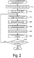
- Fig. 3 is a flowchart of the virtual chromatic value determination process.
- the virtual chromatic value determining section 20 first determines whether or not the lattice point to be processed is an endmost lattice point (Step S21).
- the endmost lattice point refers to the first or Nth lattice point in the case where the number of lattice points per one dimension is N.
- the virtual chromatic value determination process ends.
- the virtual chromatic value determining objective function generating section 21 sets an objective function for optimizing the gradation (Step S22).
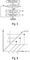
- Fig. 4 is a schematic view illustrating an outline of the process of the virtual chromatic value determining objective function generating section 21.
- Fig. 4 illustrates a case where the device color system is two-dimensional.
- y illustrated in Fig. 4 indicates a value in a dimension of a virtual chromatic value space.
- Other dimensions are also represented by y illustrated in Fig. 4 because any of the other dimensions can be independently processed.
- the virtual chromatic value determining objective function generating section 21 first determines a direction 1 illustrated in Fig. 4 as a direction of definition of a first cubic spline function.
- the virtual chromatic value determining objective function generating section 21 then identifies the lattice point to be processed by i, and identifies the two lattice points by i - 1 and i + 1, wherein the two lattice points sandwiching the lattice point to be processed in the direction of definition of the first cubic spline function and having the virtual chromatic values that are already determined.
- the values x i - 1 , x i , and x i + 1 of the device color system at the respective lattice points identified by i - 1, i, and i + 1 are defined as an independent variable, and the corresponding virtual chromatic values y i - 1 , y i , and y i + 1 are defined as a dependent variable. Note that the virtual chromatic value y i is not determined.
- the virtual chromatic value determining objective function generating section 21 determines a direction 2 illustrated in Fig. 6 as a direction of definition of a first cubic spline function, and similarly determines a set of an independent variable and a dependent variable.
- Fig. 4 illustrates a case where the device color system is two-dimensional. In a case where the device color system is of a higher dimension, combinations of independent and dependent variables are similarly determined.
- the virtual chromatic value determining objective function generating section 21 then sets an objective function for optimizing the gradation using the combinations of the independent and dependent variables determined as above using a method described in the section of a gradation optimizing objective function generation process below.
- the virtual chromatic value determining section 20 calculates the virtual chromatic value y i to minimize the objective function to determine the virtual chromatic value with optimized gradation in Step S23.
- Various methods such as typical solutions for optimization problems can be used to determine the virtual chromatic values.
- a first-order derivative parameter y' i and a second-order derivative parameter y" i of the lattice point to be processed are also determined.
- a method for calculating the first-order derivative parameter y' i and the second-order derivative parameter y" i is also described in the section of the gradation optimizing objective function generation process.
- the coefficient matrix K is a matrix with rows and columns, the number of rows corresponding to the number of dimensions of the virtual chromatic value space and the number of columns corresponding to the number of inks, and is determined based on the color developing characteristics of inks.
- elements in Equation (2) for example, are used.
- the elements of the coefficient matrix K may be determined from qualitative features of the color developing characteristics, or may be determined by a quantitative method using color measurement results of the inks.
- the conversion by Equation (1) is used in the color reproduction range determination process, the ink volume maximization process, and the ink volume determination process.
- Fig. 5 is a flowchart of a color reproduction range determination process.
- the color reproduction range determining section 30 determines whether the lattice point to be processed is a contour lattice point (Step S31).
- the contour lattice point refers to a lattice point located on the contour of a color reproduction range, and, in general, reproduces relatively higher saturation than the other lattice points.
- the color reproduction range determining section 30 does not execute the color reproduction range determination process.
- the color reproduction range determining section 30 determines a color reproduction range (Step S32).
- Fig. 6 illustrates maximization of the color reproduction range in a case of a two-dimensional contour surface.
- Fig. 6 is a schematic diagram illustrating an expanding direction v in the color reproduction range and the two-dimensional contour surface, and illustrating a virtual color space for illustrating the process of maximizing the color reproduction range.
- the expanding direction v is determined in the virtual color space.
- the expanding direction v in which the color reproduction range expands is determined as appropriate based on, for example, the characteristics of the transformation matrix K between the ink volumes and the virtual chromatic values.
- the determined expanding direction is illustrated as a vector v in Fig. 7 .
- a point of the virtual chromatic value, determined in the virtual chromatic value determination process, in the virtual color space is expressed as p v .
- the point p v of the virtual chromatic value optimizes the gradation in the virtual chromatic value.
- the point may not maximize the color reproduction range.
- the virtual chromatic value that maximizes the color reproduction range is determined to be the virtual chromatic value of the lattice point to be processed in the color reproduction range determination process.
- the virtual chromatic value determined to maximize the color reproduction range may not compatible with the virtual chromatic value with optimized gradation.
- the following limitation is placed to determine the virtual chromatic value with a maximized color reproduction range.
- Planes S 1 and S 2 illustrated in Fig. 6 serve as the limitations described above.
- the limitation planes S 1 and S 2 pass through the virtual chromatic value p v .
- the limitation plane S 1 has a normal vector in a direction 1 illustrated in Fig. 6
- the limitation plane S 2 has a normal vector in a direction 2 illustrated in Fig. 6 .
- the limitation planes S 1 and S 2 may be determined as follows. For example, in a case where the virtual chromatic value vectors of the lattice points x i - 1 and x i + 1 having virtual chromatic values that are already determined in the direction 1 illustrated in Fig.
- the limitation plane S 2 can be determined by regarding the direction 2 as the direction of definition of the normal vector of the limitation plane S 2 .
- the virtual chromatic value maximizing the color reproduction range is searched on a straight line indicated by a broken line in Fig. 6 .
- the expanding direction vector v may not be parallel with the broken line in Fig. 6 .
- the searching direction is limited to the direction of the broken line, and thus the color reproduction range is maximized in a case where the inner product of the virtual chromatic value p and the expansion vector v reaches the maximum on the broken line.
- a point with a maximized color reproduction range is searched from the point p v in the direction of the vector v s illustrated in Fig. 6 .
- the virtual chromatic value p is replaced with the ink volume q using Equation (1) to maximize the color reproduction range.
- the ink volume usage limit set in Step S11 illustrated in Fig. 2 is applied.
- the color reproduction range is maximized within an available range of the ink volume space.
- the virtual chromatic value resulting from the maximization of the color reproduction range may not exist in the arrow side of the vector v s compared with the virtual chromatic value p v illustrated in Fig. 6 , and may substantially correspond to compression of the virtual chromatic value p v .
- the virtual chromatic value vector of the lattice point to be processed with the maximized color reproduction range determined as above is defined as p i .
- the virtual chromatic value in Step S31 (No) in Fig. 5 is also referred to as p i .
- the ink volume maximizing section 40 redetermines an ink volume vector q to maximize the total ink volume while maintaining the virtual chromatic value p i obtained in the virtual chromatic value determination process or in the color reproduction range determination process.
- the correspondence relationship between the virtual chromatic value p i and the ink volume q is determined by Equation (1).
- the ink volume usage limit set in Step S11 in Fig. 2 is also applied to maximize the total ink volume within the range of the set ink volume usage limit.
- Fig. 7 is a flowchart of the ink volume determination process.
- the ink volume determining section 50 determines whether or not the lattice point to be processed is an endmost lattice point (Step S51). In the case where the lattice point to be processed is an endmost lattice point (No in Step S51), the ink volume determination process ends. In the case where the lattice point to be processed is not an endmost lattice point (Yes in Step S51), the ink volume determining objective function generating section 51 sets an objective function for optimizing the gradation (Step S52).
- the ink volume determining objective function generating section 51 defines the values x i - 1 , x i , and x i + 1 of the device color system at the respective lattice points identified by i -1, i, and i + 1 as an independent variable, and defines the corresponding ink volumes y i - 1 , y i , and y i + 1 as a dependent variable.
- the ink volume determining objective function generating section 51 then sets an objective function for optimizing the gradation using a method described in the section of the gradation optimizing objective function generation process below.
- the ink volume determining section 50 calculates the ink volume y i to minimize the objective function to determine the ink volume with the optimized gradation (Step S53).
- Various methods such as typical solutions for optimization problems can be used to determine the ink volumes.
- the ink volume usage limit set in Step S11 in Fig. 2 is to be satisfied in the ink volume determination process.
- the virtual chromatic value p i determined in the virtual chromatic value determination process or in the color reproduction range determination process and the total ink volume determined in the ink volume maximization process are also to be maintained.
- Equation (1) the relationship maintained by the virtual chromatic value p i and the ink volume to be determined can be expressed by Equation (1).
- the first-order derivative parameter y' i and the second-order derivative parameter y" i of the lattice point to be processed are also determined.
- a method for calculating the first-order derivative parameter y' i and the second-order derivative parameter y" i is also described in the section of the gradation optimizing objective function generation process.
- the process of generating the objective functions generated at the virtual chromatic value determining objective function generating section 21 and the ink volume determining objective function generating section 51 will now be described in detail.
- a generation process in which the first cubic spline function is defined in one direction (a case of one dimension) will be described as an example.
- the one-dimensional cubic spline function can be defined with respect to an independent variable x and a dependent variable y by Equation (4).
- Equation (4) has an identical gradient at x i
- Equation (5) in the interval x i ⁇ x ⁇ x i + 1 yield Equation (6).
- i is an identifier of the lattice point
- y indicates the second-order derivative parameter at the respective lattice point.
- B 1 x i ⁇ x i ⁇ 1 ⁇ 1 x i ⁇ x i ⁇ 1 0 1 x i ⁇ x i ⁇ 1 ⁇ x i + 1 ⁇ x i x i
- Equation (11) is a function of an unknown dependent variable y i .
- determining y i that minimizes Equation (11) optimizes the gradation.
- Equation (12) E i + E j + ⁇
- the virtual chromatic value determining objective function generating section 21 generates Equation (12) using the virtual chromatic value as the dependent variable of the first cubic spline function
- the ink volume determining objective function generating section 51 generates Equation (12) using the ink volume as the dependent variable of the first cubic spline function.
- the first-order derivative parameter y' i and the second-order derivative parameter y" i of the virtual chromatic value are respectively determined using Equations (5) and (7) at the virtual chromatic value determining section 20, and thus are calculated at the virtual chromatic value determining section 20.
- the first-order derivative parameter y' i and the second-order derivative parameter y" i of the ink volume are respectively determined using Equations (5) and (7) at the ink volume determining section 50, and thus are calculated at the ink volume determining section 50.
- the lattice point is the endmost lattice point, that is, the identifier i - 1 or i + 1 of the lattice point corresponds to 1 or N when the number of lattice points in one dimension is N
- y' i - 1 or y' i + 1 used in the definition of Equation (10) used in Equation (7) is undetermined.
- Fig. 8 illustrates generated ink volumes of CMYKR colors at gray lattice points in an example.
- Fig. 8 schematically illustrates increase or decrease in the CMYKR ink volumes at the gray lattice points in a color conversion table created using the method for creating the color conversion table of this embodiment.
- the solid line indicates C ink
- the dashed dotted line indicates M ink
- the dashed line indicates Y ink
- the dashed double dotted line indicates K (black) ink
- the short dashed line indicates R (red) ink.
- the volumes of the CMYKR inks in the color conversion table created using the method for creating the color conversion table of this embodiment increase or decrease smoothly.
- Fig. 9 illustrates generated ink volumes of CMYKR colors at gray lattice points in a comparative example.
- Fig. 9 schematically illustrates increase or decrease in the CMYKR ink volumes at the gray lattice points in a color conversion table created using a known method for creating a color conversion table as a comparative example.
- the increase or decrease in the CMYKR ink volumes is indicated by respective identical line types to those in Fig. 8 .
- any of the CMYKR inks do not increase or decrease smoothly compared with the example.
- the color conversion table created using the method for creating the color conversion table of the example enables printing with finer gradations in ink volumes compared with the color conversion table created using the method for creating the color conversion table of the comparative example.
- Fig. 10 illustrates the virtual chromatic value or the ink volume determined using the objective function generated in the gradation optimizing objective function generation process according to the first embodiment.
- Fig. 10 schematically illustrates an example of the virtual chromatic value calculated in the virtual chromatic value determination process or the ink volume calculated in the ink volume determination process in a case where the device color system is two-dimensional and the virtual chromatic value or the ink volume is one-dimensional.
- x indicates the space of the device color system
- y indicates the space of the virtual chromatic value or the ink volume.
- FIG. 10 illustrates a processing result in a case where y is 0 when x 1 is 0 and x 1 is maximum and where a shape of convex quadratic function is generated at y when x 2 is 0 and x 2 is maximum.
- the method for this embodiment produces the calculated virtual chromatic value or ink volume to form a saddle-like shape.
- the shape is generated with smooth gradation.
- the virtual chromatic value determining section 20 determines the virtual chromatic value using the cubic spline function connecting a plurality of lattice points by minimizing the sum of the squares of the second-order derivative parameters.
- the ink volume determining section 50 determines the combination of ink volumes assigned to each lattice point in the color conversion table using the cubic spline function connecting the plurality of lattice points to minimize the sum of the squares of the second-order derivative parameters.
- the method for creating the color conversion table according to this embodiment enables printing with finer gradation in the ink volume as well as the fine gradation in the chromatic value on print results. Moreover, the method for creating the color conversion table of this embodiment allows a color conversion table to be prepared in advance, and also allows a color conversion table to be created when the printing condition changes. This increases convenience for a printer user.
- the color reproduction range determining section 30 executes the color reproduction range determination process to maximize the color reproduction range, and the ink volume maximizing section 40 sets combinations of inks to maximize the total ink volumes, resulting in an enhancement in graininess of a printout.
- the objective function used in the virtual chromatic value determination process and in the ink volume determination process is different from the objective function used in the first embodiment, and the other processes are identical.
- the sum of the squares of the second-order derivative parameters of the first cubic spline function expressed by Equation (11) is set as the objective function per dimension in the gradation optimizing objective function generation process, and the virtual chromatic value and the ink volume at the lattice point to be processed is determined in the virtual chromatic value determination process and the ink volume determination process to minimize the objective function.
- an objective function is generated such that the first-order derivative parameters of the first and second cubic spline functions are expected to be identical to each other to the greatest extent practicable.
- the direction of definition of the second cubic spline function is identical to the direction of definition of the first cubic spline function.
- Fig. 11 is a schematic diagram illustrating the objective function according to the second embodiment in a case where the device color system is two-dimensional and the virtual chromatic value or the ink volume is one-dimensional.
- the first cubic spline function is defined by the dependent variables indicated by filled circles.
- a second cubic spline function is defined using these dependent variables and the independent variable identical to the independent variable of the first cubic spline function.
- the second cubic spline function is defined by the dependent variables indicated by hollow circles.
- the sum of the squares of the differences between the first-order derivative parameters of the first and second cubic spline functions is generated as an objective function.
- the another lattice points adjacent in the direction of x 2 also exist in the negative direction of x 2 .
- the number of directions different from the direction of definition of the first and second cubic spline functions that is, directions in which adjacent relations are defined, increases.
- the corresponding terms can be added up in the objective function.
- the direction of definition of the first cubic spline function can be selected as many as the number of dimensions of the independent variable. These terms can also be added up in the objective function.
- the first-order derivative parameter of the cubic spline function can be determined using the calculation method described in the first embodiment.
- the first-order derivative parameter of the cubic spline is expressed as a partial derivative of the vector in Equation (13).
- the coefficient terms of 1/(x j - x j - 1 ) 2 , 1/(x j + 1 - x j ) 2 , 1/(x i - x i - 1 ) 2 , and 1/(x i + 1 - x i ) 2 in Equation (13) are intended as correction in a case where intervals between the lattice points are uneven.
- the first-order derivative parameters ⁇ y/ ⁇ x in Equation (13) can be determined as y' in Equation (5) described in the first embodiment, and the second-order derivative parameters y" used in the right side of Equation (5) can also be determined using Equation (7) described in the first embodiment.
- the objective function acquired as Equation (13) is a function of an unknown dependent variable y i, j as in the first embodiment.
- the unknown dependent variable in Equation (7) is expressed as y i .
- Fig. 12 illustrates the virtual chromatic value or the ink volume determined using the objective function generated in the gradation optimizing objective function generation process according to the second embodiment or a third embodiment.
- Fig. 12 illustrates an example of the virtual chromatic value calculated in the virtual chromatic value determination process or the ink volume calculated in the ink volume determination process in the second embodiment under the condition identical to the condition in Fig. 10 of the first embodiment.
- the objective function substituting the sum of the squares of the second-order derivative parameters of the first cubic spline functions of the first embodiment is set in the gradation optimizing objective function generation process as described above.
- the objective function set in the second embodiment is the sum of the squares of the differences between the first-order derivative parameters of the first and second cubic spline functions in the direction along which the first and second cubic spline functions are adjacent to each other.
- the virtual chromatic value determining section 20 and the ink volume determining section 50 according to the second embodiment respectively determine the virtual chromatic value and the ink volume to minimize the objective function.
- the virtual chromatic value or the ink volume that changes smoothly is also determined in a case where, for example, the curvature of the curved surface (a hypersurface in a case of a device color system in three or more dimensions) is large for some reason such as maximization of the color reproduction range while the curvature is maintained.
- the objective function used in the virtual chromatic value determination process and in the ink volume determination process is different from the objective function used in the second embodiment, and the other processes are identical.
- the sum of the squares of the differences between the first-order derivative parameters of the first cubic spline function and the first-order derivative parameters of the second cubic spline function defined adjacent to the first cubic spline function expressed by Equation (13) in the direction along which the first and second cubic spline functions are adjacent to each other is set as the objective function in the gradation optimizing objective function generation process, and the virtual chromatic value and the ink volume at the lattice point to be processed are respectively determined in the virtual chromatic value determination process and the ink volume determination process to minimize the objective function.
- the sum of the squares of the differences between the second-order derivative parameters of the first cubic spline function and the second-order derivative parameters of the second cubic spline function defined adjacent to the first cubic spline function in the direction along which the first and second cubic spline functions are adjacent to each other is generated as an objective function.
- Equation (13) are replaced with the second-order derivatives in Equation (14), which is defined as the objective function of the third embodiment.
- Equation (14) is also an example of a case where the device color system is two-dimensional and the virtual chromatic value or the ink volume is one-dimensional as is Equation (13).
- Equation (14) The second-order derivative parameters ⁇ 2 y/ ⁇ x 2 in Equation (14) can be determined from y" in Equation (7) described in the first embodiment.
- the objective function derived by Equation (14) is a function of an unknown dependent variable yi,j as are the objective functions in the first and second embodiments.
- the result of calculation of the virtual chromatic value in the virtual chromatic value determination process or the ink volume in the ink volume determination process in the third embodiment under the condition identical to the condition in Fig. 10 of the first embodiment and the condition in Fig. 12 of the second embodiment is substantially identical to the result illustrated in Fig. 12 of the second embodiment.
- the virtual chromatic value or the ink volume determined in the third embodiment also has features similar to the features of the second embodiment.
- the objective function using the second-order derivative parameters instead of the first-order derivative parameters included in the objective function of the second embodiment is generated in the gradation optimizing objective function generation process as described above.
- the objective function set in the third embodiment is the sum of the squares of the differences between the second-order derivative parameters of the first and second cubic spline functions in the direction along which the first and second cubic spline functions are adjacent to each other.
- the virtual chromatic value determining section 20 and the ink volume determining section 50 according to the third embodiment respectively determine the virtual chromatic value and the ink volume to minimize the objective function.
- the virtual chromatic value or the ink volume that changes smoothly is also determined in a case where the curvature of the hypersurface is large for some reason while the curvature is maintained as in the second embodiment.
- both the virtual chromatic value and the ink volume are respectively determined in the virtual chromatic value determination process and in the ink volume determination process using the objective functions generated in the gradation optimizing objective function generation process.
- selection of the processes in which the objective functions are used can be modified in various ways. For example, either the virtual chromatic value or the ink volume may be determined in the virtual chromatic value determination process or in the volume determination process, respectively, using the objective functions generated in the gradation optimizing objective function generation process.
- various processes other than the virtual chromatic value determination process and the ink volume determination process are executed.
- these various processes are optional, and may not be executed.
- the ink volume setting for the specific lattice point in Step S12 may not be performed, and the ink volumes of the entire lattice points may be calculated.
- the color reproduction range determination process in Step S30 may not be executed.
- the ink volume maximization process in Step S40 may not be executed.
- the color conversion table creating module 100 of the first embodiment determines the color conversion table including the inks of CMYK and R, which is a specific feature.
- CMYK and R which is a specific feature.
- various modifications are possible.
- light color inks such as Lc (light cyan), Lm (light magenta), and Lk (light gray) may be added.
- other specific colors may be used.
- N The number of lattice points, p, p v ... Virtual chromatic value vector, q ... Ink volume vector, K ... Transformation matrix, i, j ... Lattice point position identifier, x ... Independent variable, y ... Dependent variable, A, B ... Matrix, c ... Vector, E ... Objective function, v, v s ... Color reproduction range expanding direction, S 1 , S 2 ... Limitation plane, 10 ... Lattice point selecting section, 20 ... Virtual chromatic value determining section, 21 ... Virtual chromatic value determining objective function generating section, 30 ... Color reproduction range determining section, 40 ... Ink volume maximizing section, 50 ... Ink volume determining section, 51 ... Ink volume determining objective function generating section, 100 ... Color conversion table creating module
Landscapes
- Engineering & Computer Science (AREA)
- Multimedia (AREA)
- Signal Processing (AREA)
- Physics & Mathematics (AREA)
- General Physics & Mathematics (AREA)
- Theoretical Computer Science (AREA)
- General Engineering & Computer Science (AREA)
- Mathematical Physics (AREA)
- Facsimile Image Signal Circuits (AREA)
- Image Processing (AREA)
- Color Image Communication Systems (AREA)
Claims (5)
- Verfahren zum Erstellen einer Farbumwandlungstabelle zum Bestimmen eines Tintenvolumens, das von einem Drucker abgegeben wird, das Verfahren umfassend:einen virtuellen Farbwertbestimmungsschritt (S20) zum Bestimmen mehrerer virtueller Farbwerte (y) an einem Gitterpunkt in einer Farbumwandlungstabelle in einem virtuellen Farbraum; undeinen Tintenvolumenbestimmungsschritt (S50) zum Bestimmen einer Kombination der Tintenvolumina an dem Gitterpunkt in der Farbumwandlungstabelle basierend auf einem vorbestimmten Transformationskoeffizienten und dem virtuellen Farbwert, wobeimindestens einer von dem virtuellen Farbwertbestimmungsschritt oder dem Tintenvolumenbestimmungsschritt unter Verwendung einer kubischen Spline-Funktion durchgeführt wird, die durch die mehreren virtuellen Farbwerte oder das Tintenvolumen definiert ist; und wobeimindestens einer von dem virtuellen Farbwertbestimmungsschritt (S20) oder dem Tintenvolumenbestimmungsschritt (S50) eine erste kubische Spline-Funktion definiert, wobei die erste kubische Spline-Funktion den virtuellen Farbwert oder das Tintenvolumen als eine abhängige Variable (yi-1, yi, yi+1) aufweist und einen Wert des Gitterpunkts in der Farbumwandlungstabelle als eine unabhängig Variable (xi-1 xi, xi+1) in Bezug auf die zu verarbeitenden drei aufeinanderfolgenden Gitterpunkte aufweist, wobei die zu verarbeitenden drei aufeinanderfolgenden Gitterpunkte einen Zwischengitterpunkt (i), an dem der virtuelle Farbwert oder das Tintenvolumen zu bestimmen ist, und zwei Endgitterpunkt (i-1, i+1), an welchen die virtuellen Farbwerte oder die Tintenvolumina bereits bestimmt sind, zwischen welchen der Zwischengitterpunkt liegt, aufweist, undden virtuellen Farbwert oder das Tintenvolumen an dem Zwischengitterpunkt bestimmt, um eine Summe von Quadraten von Ableitungsparametern zweiter Ordnung (y"i) der ersten kubischen Spline-Funktion an den zu verarbeitenden drei Gitterpunkten zu minimieren.
- Verfahren zum Erstellen der Farbumwandlungstabelle nach Anspruch 1, wobei
mindestens einer von dem virtuellen Farbwertbestimmungsschritt oder dem Tintenvolumenbestimmungsschritt
eine zweite kubische Spline-Funktion definiert, wobei die zweite kubische Spline-Funktion den virtuellen Farbwert oder das Tintenvolumen als eine abhängige Variable und einen Wert eines Gitterpunkts in einem Vorrichtungsfarbsystem als eine unabhängige Variable in Bezug auf andere drei Gitterpunkte aufweist, deren virtuelle Farbwerte und Tintenvolumina bereits bestimmt sind, wobei die anderen drei Gitterpunkte jeweils an die zu verarbeitenden drei Gitterpunkte in einer Richtung angrenzen, die sich von einer Definitionsrichtung der ersten kubischen Spline-Funktion unterscheidet, wobei die zweite kubische Spline-Funktion in einer Richtung definiert wird, die mit der Definitionsrichtung der ersten kubischen Spline-Funktion identisch ist, und
den virtuellen Farbwert oder das Tintenvolumen an dem Zwischengitterpunkt bestimmt, um eine Summe von Quadraten von Differenzen zwischen einem Ableitungsparameter erster Ordnung (y'i), der durch die erste kubische Spline-Funktion bestimmt wird, und einem Ableitungsparameter erster Ordnung, der durch die zweite kubische Spline-Funktion bestimmt wird, entsprechender Sätze der Gitterpunkte, die in der Richtung, die sich von der Definitionsrichtung der ersten und zweiten kubischen Spline-Funktion unterscheidet, angrenzen, zu minimieren. - Verfahren zum Erstellen der Farbumwandlungstabelle nach Anspruch 1, wobei
mindestens einer von dem virtuellen Farbwertbestimmungsschritt oder dem Tintenvolumenbestimmungsschritt
eine zweite kubische Spline-Funktion definiert, wobei die zweite kubische Spline-Funktion den virtuellen Farbwert oder das Tintenvolumen als eine abhängige Variable und einen Wert eines Gitterpunkts in einem Vorrichtungsfarbsystem als eine unabhängige Variable in Bezug auf andere drei Gitterpunkte aufweist, deren virtuelle Farbwerte und Tintenvolumina bereits bestimmt sind, wobei die anderen drei Gitterpunkte jeweils an die zu verarbeitenden drei Gitterpunkte in einer Richtung angrenzen, die sich von einer Definitionsrichtung der ersten kubischen Spline-Funktion unterscheidet, wobei die zweite kubische Spline-Funktion in einer Richtung definiert wird, die mit der Definitionsrichtung der ersten kubischen Spline-Funktion identisch ist, und
den virtuellen Farbwert oder das Tintenvolumen an dem Zwischengitterpunkt bestimmt, um eine Summe von Quadraten von Differenzen zwischen einem Ableitungsparameter zweiter Ordnung, der durch die erste kubische Spline-Funktion bestimmt wird, und einem Ableitungsparameter zweiter Ordnung, der durch die zweite kubische Spline-Funktion bestimmt wird, entsprechender Sätze der Gitterpunkte, die in der Richtung angrenzen, die sich von einer Definitionsrichtung der ersten und zweiten kubischen Spline-Funktion unterscheidet, zu minimieren. - Verfahren zum Erstellen der Farbumwandlungstabelle nach einem vorstehenden Anspruch, weiter umfassend:einen Farbwiedergabebereichsbestimmungsschritt (S30) zum Maximieren eines Farbwiedergabebereichs in dem virtuellen Farbraum vor dem Tintenvolumenbestimmungsschritt.
- Verfahren zum Erstellen der Farbumwandlungstabelle nach einem der Ansprüche 1 bis 4, weiter umfassend:einen Tintenvolumenmaximierungsschritt (S40) zum Erhöhen einer Gesamtsumme von Werten der Tintenvolumina.
Applications Claiming Priority (2)
| Application Number | Priority Date | Filing Date | Title |
|---|---|---|---|
| JP2015247233 | 2015-12-18 | ||
| PCT/JP2016/085935 WO2017104449A1 (ja) | 2015-12-18 | 2016-12-02 | 色変換テーブルの作成方法 |
Publications (3)
| Publication Number | Publication Date |
|---|---|
| EP3393115A1 EP3393115A1 (de) | 2018-10-24 |
| EP3393115A4 EP3393115A4 (de) | 2019-08-07 |
| EP3393115B1 true EP3393115B1 (de) | 2021-08-18 |
Family
ID=59056369
Family Applications (1)
| Application Number | Title | Priority Date | Filing Date |
|---|---|---|---|
| EP16875432.3A Active EP3393115B1 (de) | 2015-12-18 | 2016-12-02 | Verfahren zur erstellung einer farbumwandlungstabelle |
Country Status (5)
| Country | Link |
|---|---|
| US (1) | US10540582B2 (de) |
| EP (1) | EP3393115B1 (de) |
| JP (2) | JPWO2017104449A1 (de) |
| CN (1) | CN108370404B (de) |
| WO (1) | WO2017104449A1 (de) |
Families Citing this family (3)
| Publication number | Priority date | Publication date | Assignee | Title |
|---|---|---|---|---|
| JP7103183B2 (ja) | 2018-11-16 | 2022-07-20 | セイコーエプソン株式会社 | 色変換プロファイル作成装置、色変換プロファイルの作成方法およびそのためのプログラム |
| CN109706759A (zh) * | 2018-12-29 | 2019-05-03 | 杭州智数创联科技有限公司 | 一种基于色域面积的数码印花单通道墨量限制方法 |
| JP2021158398A (ja) * | 2020-03-25 | 2021-10-07 | セイコーエプソン株式会社 | 教師データの作成方法、色予測モデル作成装置および色予測モデル作成方法 |
Family Cites Families (34)
| Publication number | Priority date | Publication date | Assignee | Title |
|---|---|---|---|---|
| DE4012905A1 (de) * | 1990-04-23 | 1991-10-24 | Linotype Ag | Verfahren und vorrichtung zur erzeugung einer digitalen drucktabelle fuer druckfarben bei bildreproduktionsgeraeten |
| JP2004015146A (ja) * | 2002-06-04 | 2004-01-15 | Mitsubishi Electric Corp | 画像処理装置および画像処理方法 |
| JP3956124B2 (ja) | 2002-10-17 | 2007-08-08 | セイコーエプソン株式会社 | 対応関係定義データ作成用格子点決定方法、画像処理装置、画像処理方法および画像処理プログラム |
| US7440135B2 (en) | 2002-10-17 | 2008-10-21 | Seiko Epson Corporation | Determining method for lattice point for correspondence definition data creation and image processor |
| JP3956125B2 (ja) | 2002-10-17 | 2007-08-08 | セイコーエプソン株式会社 | 対応関係定義データ作成用格子点決定方法、画像処理装置、画像処理方法および画像処理プログラム |
| JP2004320627A (ja) | 2003-04-18 | 2004-11-11 | Seiko Epson Corp | 対応関係定義データ作成用格子点決定システム、対応関係定義データ作成用格子点要求クライアント、対応関係定義データ作成用格子点決定サーバおよびその方法並びにプログラム |
| JP4200365B2 (ja) | 2003-04-18 | 2008-12-24 | セイコーエプソン株式会社 | 対応関係定義データ作成用格子点決定方法、対応関係定義データ作成用格子点決定装置、対応関係定義データ作成用格子点決定プログラム、印刷制御装置、印刷制御方法、印刷制御プログラムおよび画像データ処理装置 |
| JP2004320624A (ja) | 2003-04-18 | 2004-11-11 | Seiko Epson Corp | 対応関係定義データ作成用格子点決定方法、対応関係定義データ作成用格子点決定装置、対応関係定義データ作成用格子点決定プログラム、印刷制御装置、印刷制御方法および印刷制御プログラム |
| JP2004320625A (ja) | 2003-04-18 | 2004-11-11 | Seiko Epson Corp | 対応関係定義データ作成用格子点決定方法、対応関係定義データ作成用格子点決定装置、対応関係定義データ作成用格子点決定プログラム、印刷制御装置、印刷制御方法および印刷制御プログラム |
| US7652789B2 (en) | 2003-11-03 | 2010-01-26 | Seiko Epson Corporation | Production of color conversion profile for printing |
| US7605943B2 (en) | 2003-11-03 | 2009-10-20 | Seiko Epson Corporation | Production of a color conversion profile utilizing comparison of spectral reflectance data and comparative colors |
| US7706604B2 (en) | 2003-11-03 | 2010-04-27 | Seiko Epson Corporation | Production of color conversion profile for printing |
| US7440136B2 (en) * | 2003-12-15 | 2008-10-21 | Canon Kabushiki Kaisha | Color processing apparatus and method |
| JP4434842B2 (ja) | 2004-06-02 | 2010-03-17 | セイコーエプソン株式会社 | プロファイル作成装置 |
| JP4492358B2 (ja) | 2005-01-12 | 2010-06-30 | セイコーエプソン株式会社 | 格子点配置の平滑化 |
| JP4582310B2 (ja) | 2005-02-02 | 2010-11-17 | セイコーエプソン株式会社 | プロファイル作成方法、プロファイル作成装置、プロファイル作成プログラム、及び印刷制御装置 |
| JP4595734B2 (ja) | 2005-08-03 | 2010-12-08 | セイコーエプソン株式会社 | プロファイル作成方法、プロファイル作成装置、プロファイル作成プログラム、印刷制御方法、印刷制御装置、及び印刷制御プログラム |
| JP2008230049A (ja) * | 2007-03-20 | 2008-10-02 | Seiko Epson Corp | 色材の組み合わせに応じた印刷制御 |
| JP4996338B2 (ja) * | 2007-05-21 | 2012-08-08 | キヤノン株式会社 | 色処理方法および色処理装置 |
| JP4941152B2 (ja) | 2007-07-24 | 2012-05-30 | セイコーエプソン株式会社 | 色変換ルックアップテーブル作成装置及び方法、並びに、そのためのプログラム |
| JP4924458B2 (ja) | 2008-02-05 | 2012-04-25 | セイコーエプソン株式会社 | 色変換対応情報作成装置及び方法、そのためのプログラム、並びに、印刷装置の製造システム及び方法 |
| JP5256495B2 (ja) * | 2009-03-24 | 2013-08-07 | コニカミノルタ株式会社 | 変換特性連続性向上処理方法、プロファイル平滑化方法、色変換装置、および色変換プログラム |
| JP2010245966A (ja) | 2009-04-08 | 2010-10-28 | Seiko Epson Corp | 色変換プロファイル作成装置、方法、プログラム、および、印刷装置 |
| JP4683145B2 (ja) * | 2009-08-24 | 2011-05-11 | セイコーエプソン株式会社 | 印刷装置、印刷方法および印刷プログラム |
| JP2011151491A (ja) * | 2010-01-19 | 2011-08-04 | Fuji Xerox Co Ltd | 色変換装置及び色変換プログラム |
| JP5589520B2 (ja) | 2010-04-09 | 2014-09-17 | セイコーエプソン株式会社 | 色変換プロファイル作成装置、色変換プロファイル作成方法、色変換プロファイル作成プログラムおよび印刷装置 |
| JP2011223392A (ja) | 2010-04-12 | 2011-11-04 | Seiko Epson Corp | 色変換テーブル作成方法および色変換テーブル作成装置 |
| JP2011223434A (ja) | 2010-04-13 | 2011-11-04 | Seiko Epson Corp | 色変換テーブル作成方法、色変換テーブル作成プログラムおよび印刷装置 |
| JP2012129905A (ja) | 2010-12-17 | 2012-07-05 | Seiko Epson Corp | 色変換プロファイル作成装置、色変換プロファイル作成方法、色変換プロファイル作成プログラム及び印刷装置 |
| JP2012217075A (ja) | 2011-04-01 | 2012-11-08 | Seiko Epson Corp | 印刷装置の製造方法、プロファイル作成方法、印刷方法 |
| JP2012231308A (ja) * | 2011-04-26 | 2012-11-22 | Seiko Epson Corp | 印刷装置の製造方法、印刷装置、及び、印刷方法 |
| JP2013063550A (ja) * | 2011-09-16 | 2013-04-11 | Seiko Epson Corp | 画像処理装置、画像処理方法、及び画像処理プログラム |
| JP2015142250A (ja) | 2014-01-29 | 2015-08-03 | セイコーエプソン株式会社 | 色変換対応情報作成装置、方法、プログラム、印刷装置の製造システム及び製造方法 |
| CN104320561B (zh) * | 2014-10-31 | 2017-12-05 | 上海出版印刷高等专科学校 | 基于墨量最佳利用多级打印系统控制方法 |
-
2016
- 2016-12-02 EP EP16875432.3A patent/EP3393115B1/de active Active
- 2016-12-02 JP JP2017555980A patent/JPWO2017104449A1/ja active Pending
- 2016-12-02 CN CN201680073824.9A patent/CN108370404B/zh active Active
- 2016-12-02 US US16/062,837 patent/US10540582B2/en active Active
- 2016-12-02 WO PCT/JP2016/085935 patent/WO2017104449A1/ja not_active Ceased
-
2021
- 2021-03-03 JP JP2021033193A patent/JP7052895B2/ja active Active
Also Published As
| Publication number | Publication date |
|---|---|
| JP7052895B2 (ja) | 2022-04-12 |
| JPWO2017104449A1 (ja) | 2018-10-04 |
| CN108370404B (zh) | 2019-09-06 |
| CN108370404A (zh) | 2018-08-03 |
| JP2021100264A (ja) | 2021-07-01 |
| EP3393115A1 (de) | 2018-10-24 |
| US10540582B2 (en) | 2020-01-21 |
| WO2017104449A1 (ja) | 2017-06-22 |
| EP3393115A4 (de) | 2019-08-07 |
| US20190026611A1 (en) | 2019-01-24 |
Similar Documents
| Publication | Publication Date | Title |
|---|---|---|
| EP3213501B1 (de) | Konfigurierung eines bildgebungssystems | |
| US8131070B2 (en) | Color processing apparatus, color processing method, computer readable medium and computer data signal | |
| US8358839B2 (en) | Local regression methods and systems for image processing systems | |
| EP3393115B1 (de) | Verfahren zur erstellung einer farbumwandlungstabelle | |
| EP2076016A2 (de) | Farbverarbeitungsvorrichtung und Steuerverfahren dafür | |
| US7012714B2 (en) | Color processing method, and system with coverage restriction | |
| US8149456B2 (en) | Color processing method and image forming apparatus for creating a color separation table | |
| JP5589520B2 (ja) | 色変換プロファイル作成装置、色変換プロファイル作成方法、色変換プロファイル作成プログラムおよび印刷装置 | |
| US7304767B2 (en) | Color processing method, storage medium, color processing apparatus, color transforming apparatus, and image forming apparatus | |
| US8462385B2 (en) | Color matching for color management systems | |
| JP4434842B2 (ja) | プロファイル作成装置 | |
| JP6610237B2 (ja) | 色変換テーブルの作成方法、コンピュータープログラム、および色変換テーブルの作成装置 | |
| JP4646567B2 (ja) | 色変換テーブル作成方法および画像処理装置 | |
| CN102171052A (zh) | 程序、图像形成方法以及印刷系统 | |
| US8120617B2 (en) | Color conversion with many input channels | |
| JP2009130846A (ja) | 色処理方法および画像形成装置 | |
| EP3432566B1 (de) | Verfahren zur erzeugung von farbkorrekturtabellen, vorrichtung zur erzeugung von farbkorrekturtabellen und programm | |
| JP7103183B2 (ja) | 色変換プロファイル作成装置、色変換プロファイルの作成方法およびそのためのプログラム | |
| JP2010141831A (ja) | 印刷制御装置、印刷システムおよび印刷制御プログラム | |
| JP6700707B2 (ja) | 画像形成装置 | |
| JP2020065196A (ja) | 色変換テーブル生成装置、色変換テーブル生成方法、及び色変換テーブル生成プログラム | |
| US10996902B2 (en) | Parallel processing of monochromatic print jobs using data-processing color channels of color printing device that correspond to different color colorants | |
| JP2005333575A (ja) | プロファイル作成装置、プロファイル作成方法、プロファイル作成プログラム、印刷制御装置、印刷制御方法および印刷制御プログラム | |
| JP2012124809A (ja) | 色変換テーブル補正装置、色変換テーブル補正方法、色変換テーブル補正プログラムおよび印刷制御装置 | |
| JP2006319516A (ja) | 複数の色変換プロファイルに基づく色変換 |
Legal Events
| Date | Code | Title | Description |
|---|---|---|---|
| STAA | Information on the status of an ep patent application or granted ep patent |
Free format text: STATUS: THE INTERNATIONAL PUBLICATION HAS BEEN MADE |
|
| PUAI | Public reference made under article 153(3) epc to a published international application that has entered the european phase |
Free format text: ORIGINAL CODE: 0009012 |
|
| STAA | Information on the status of an ep patent application or granted ep patent |
Free format text: STATUS: REQUEST FOR EXAMINATION WAS MADE |
|
| 17P | Request for examination filed |
Effective date: 20180718 |
|
| AK | Designated contracting states |
Kind code of ref document: A1 Designated state(s): AL AT BE BG CH CY CZ DE DK EE ES FI FR GB GR HR HU IE IS IT LI LT LU LV MC MK MT NL NO PL PT RO RS SE SI SK SM TR |
|
| AX | Request for extension of the european patent |
Extension state: BA ME |
|
| DAV | Request for validation of the european patent (deleted) | ||
| DAX | Request for extension of the european patent (deleted) | ||
| A4 | Supplementary search report drawn up and despatched |
Effective date: 20190709 |
|
| RIC1 | Information provided on ipc code assigned before grant |
Ipc: B41J 2/525 20060101ALI20190703BHEP Ipc: H04N 1/60 20060101ALI20190703BHEP Ipc: H04N 1/46 20060101AFI20190703BHEP Ipc: G06T 1/00 20060101ALI20190703BHEP |
|
| GRAP | Despatch of communication of intention to grant a patent |
Free format text: ORIGINAL CODE: EPIDOSNIGR1 |
|
| STAA | Information on the status of an ep patent application or granted ep patent |
Free format text: STATUS: GRANT OF PATENT IS INTENDED |
|
| INTG | Intention to grant announced |
Effective date: 20210526 |
|
| GRAS | Grant fee paid |
Free format text: ORIGINAL CODE: EPIDOSNIGR3 |
|
| GRAA | (expected) grant |
Free format text: ORIGINAL CODE: 0009210 |
|
| STAA | Information on the status of an ep patent application or granted ep patent |
Free format text: STATUS: THE PATENT HAS BEEN GRANTED |
|
| AK | Designated contracting states |
Kind code of ref document: B1 Designated state(s): AL AT BE BG CH CY CZ DE DK EE ES FI FR GB GR HR HU IE IS IT LI LT LU LV MC MK MT NL NO PL PT RO RS SE SI SK SM TR |
|
| REG | Reference to a national code |
Ref country code: GB Ref legal event code: FG4D |
|
| REG | Reference to a national code |
Ref country code: CH Ref legal event code: EP |
|
| REG | Reference to a national code |
Ref country code: DE Ref legal event code: R096 Ref document number: 602016062542 Country of ref document: DE |
|
| REG | Reference to a national code |
Ref country code: IE Ref legal event code: FG4D Ref country code: AT Ref legal event code: REF Ref document number: 1422695 Country of ref document: AT Kind code of ref document: T Effective date: 20210915 |
|
| REG | Reference to a national code |
Ref country code: LT Ref legal event code: MG9D |
|
| REG | Reference to a national code |
Ref country code: NL Ref legal event code: MP Effective date: 20210818 |
|
| REG | Reference to a national code |
Ref country code: AT Ref legal event code: MK05 Ref document number: 1422695 Country of ref document: AT Kind code of ref document: T Effective date: 20210818 |
|
| PG25 | Lapsed in a contracting state [announced via postgrant information from national office to epo] |
Ref country code: LT Free format text: LAPSE BECAUSE OF FAILURE TO SUBMIT A TRANSLATION OF THE DESCRIPTION OR TO PAY THE FEE WITHIN THE PRESCRIBED TIME-LIMIT Effective date: 20210818 Ref country code: BG Free format text: LAPSE BECAUSE OF FAILURE TO SUBMIT A TRANSLATION OF THE DESCRIPTION OR TO PAY THE FEE WITHIN THE PRESCRIBED TIME-LIMIT Effective date: 20211118 Ref country code: AT Free format text: LAPSE BECAUSE OF FAILURE TO SUBMIT A TRANSLATION OF THE DESCRIPTION OR TO PAY THE FEE WITHIN THE PRESCRIBED TIME-LIMIT Effective date: 20210818 Ref country code: HR Free format text: LAPSE BECAUSE OF FAILURE TO SUBMIT A TRANSLATION OF THE DESCRIPTION OR TO PAY THE FEE WITHIN THE PRESCRIBED TIME-LIMIT Effective date: 20210818 Ref country code: FI Free format text: LAPSE BECAUSE OF FAILURE TO SUBMIT A TRANSLATION OF THE DESCRIPTION OR TO PAY THE FEE WITHIN THE PRESCRIBED TIME-LIMIT Effective date: 20210818 Ref country code: ES Free format text: LAPSE BECAUSE OF FAILURE TO SUBMIT A TRANSLATION OF THE DESCRIPTION OR TO PAY THE FEE WITHIN THE PRESCRIBED TIME-LIMIT Effective date: 20210818 Ref country code: NO Free format text: LAPSE BECAUSE OF FAILURE TO SUBMIT A TRANSLATION OF THE DESCRIPTION OR TO PAY THE FEE WITHIN THE PRESCRIBED TIME-LIMIT Effective date: 20211118 Ref country code: PT Free format text: LAPSE BECAUSE OF FAILURE TO SUBMIT A TRANSLATION OF THE DESCRIPTION OR TO PAY THE FEE WITHIN THE PRESCRIBED TIME-LIMIT Effective date: 20211220 Ref country code: RS Free format text: LAPSE BECAUSE OF FAILURE TO SUBMIT A TRANSLATION OF THE DESCRIPTION OR TO PAY THE FEE WITHIN THE PRESCRIBED TIME-LIMIT Effective date: 20210818 Ref country code: SE Free format text: LAPSE BECAUSE OF FAILURE TO SUBMIT A TRANSLATION OF THE DESCRIPTION OR TO PAY THE FEE WITHIN THE PRESCRIBED TIME-LIMIT Effective date: 20210818 |
|
| PG25 | Lapsed in a contracting state [announced via postgrant information from national office to epo] |
Ref country code: PL Free format text: LAPSE BECAUSE OF FAILURE TO SUBMIT A TRANSLATION OF THE DESCRIPTION OR TO PAY THE FEE WITHIN THE PRESCRIBED TIME-LIMIT Effective date: 20210818 Ref country code: LV Free format text: LAPSE BECAUSE OF FAILURE TO SUBMIT A TRANSLATION OF THE DESCRIPTION OR TO PAY THE FEE WITHIN THE PRESCRIBED TIME-LIMIT Effective date: 20210818 Ref country code: GR Free format text: LAPSE BECAUSE OF FAILURE TO SUBMIT A TRANSLATION OF THE DESCRIPTION OR TO PAY THE FEE WITHIN THE PRESCRIBED TIME-LIMIT Effective date: 20211119 |
|
| PG25 | Lapsed in a contracting state [announced via postgrant information from national office to epo] |
Ref country code: NL Free format text: LAPSE BECAUSE OF FAILURE TO SUBMIT A TRANSLATION OF THE DESCRIPTION OR TO PAY THE FEE WITHIN THE PRESCRIBED TIME-LIMIT Effective date: 20210818 |
|
| PG25 | Lapsed in a contracting state [announced via postgrant information from national office to epo] |
Ref country code: DK Free format text: LAPSE BECAUSE OF FAILURE TO SUBMIT A TRANSLATION OF THE DESCRIPTION OR TO PAY THE FEE WITHIN THE PRESCRIBED TIME-LIMIT Effective date: 20210818 |
|
| REG | Reference to a national code |
Ref country code: DE Ref legal event code: R097 Ref document number: 602016062542 Country of ref document: DE |
|
| PG25 | Lapsed in a contracting state [announced via postgrant information from national office to epo] |
Ref country code: SM Free format text: LAPSE BECAUSE OF FAILURE TO SUBMIT A TRANSLATION OF THE DESCRIPTION OR TO PAY THE FEE WITHIN THE PRESCRIBED TIME-LIMIT Effective date: 20210818 Ref country code: SK Free format text: LAPSE BECAUSE OF FAILURE TO SUBMIT A TRANSLATION OF THE DESCRIPTION OR TO PAY THE FEE WITHIN THE PRESCRIBED TIME-LIMIT Effective date: 20210818 Ref country code: RO Free format text: LAPSE BECAUSE OF FAILURE TO SUBMIT A TRANSLATION OF THE DESCRIPTION OR TO PAY THE FEE WITHIN THE PRESCRIBED TIME-LIMIT Effective date: 20210818 Ref country code: EE Free format text: LAPSE BECAUSE OF FAILURE TO SUBMIT A TRANSLATION OF THE DESCRIPTION OR TO PAY THE FEE WITHIN THE PRESCRIBED TIME-LIMIT Effective date: 20210818 Ref country code: CZ Free format text: LAPSE BECAUSE OF FAILURE TO SUBMIT A TRANSLATION OF THE DESCRIPTION OR TO PAY THE FEE WITHIN THE PRESCRIBED TIME-LIMIT Effective date: 20210818 Ref country code: AL Free format text: LAPSE BECAUSE OF FAILURE TO SUBMIT A TRANSLATION OF THE DESCRIPTION OR TO PAY THE FEE WITHIN THE PRESCRIBED TIME-LIMIT Effective date: 20210818 |
|
| PLBE | No opposition filed within time limit |
Free format text: ORIGINAL CODE: 0009261 |
|
| STAA | Information on the status of an ep patent application or granted ep patent |
Free format text: STATUS: NO OPPOSITION FILED WITHIN TIME LIMIT |
|
| 26N | No opposition filed |
Effective date: 20220519 |
|
| PG25 | Lapsed in a contracting state [announced via postgrant information from national office to epo] |
Ref country code: MC Free format text: LAPSE BECAUSE OF FAILURE TO SUBMIT A TRANSLATION OF THE DESCRIPTION OR TO PAY THE FEE WITHIN THE PRESCRIBED TIME-LIMIT Effective date: 20210818 Ref country code: IT Free format text: LAPSE BECAUSE OF FAILURE TO SUBMIT A TRANSLATION OF THE DESCRIPTION OR TO PAY THE FEE WITHIN THE PRESCRIBED TIME-LIMIT Effective date: 20210818 |
|
| REG | Reference to a national code |
Ref country code: CH Ref legal event code: PL |
|
| GBPC | Gb: european patent ceased through non-payment of renewal fee |
Effective date: 20211202 |
|
| PG25 | Lapsed in a contracting state [announced via postgrant information from national office to epo] |
Ref country code: SI Free format text: LAPSE BECAUSE OF FAILURE TO SUBMIT A TRANSLATION OF THE DESCRIPTION OR TO PAY THE FEE WITHIN THE PRESCRIBED TIME-LIMIT Effective date: 20210818 |
|
| REG | Reference to a national code |
Ref country code: BE Ref legal event code: MM Effective date: 20211231 |
|
| PG25 | Lapsed in a contracting state [announced via postgrant information from national office to epo] |
Ref country code: LU Free format text: LAPSE BECAUSE OF NON-PAYMENT OF DUE FEES Effective date: 20211202 Ref country code: IE Free format text: LAPSE BECAUSE OF NON-PAYMENT OF DUE FEES Effective date: 20211202 Ref country code: GB Free format text: LAPSE BECAUSE OF NON-PAYMENT OF DUE FEES Effective date: 20211202 |
|
| PG25 | Lapsed in a contracting state [announced via postgrant information from national office to epo] |
Ref country code: FR Free format text: LAPSE BECAUSE OF NON-PAYMENT OF DUE FEES Effective date: 20211231 Ref country code: BE Free format text: LAPSE BECAUSE OF NON-PAYMENT OF DUE FEES Effective date: 20211231 |
|
| PG25 | Lapsed in a contracting state [announced via postgrant information from national office to epo] |
Ref country code: LI Free format text: LAPSE BECAUSE OF NON-PAYMENT OF DUE FEES Effective date: 20211231 Ref country code: CH Free format text: LAPSE BECAUSE OF NON-PAYMENT OF DUE FEES Effective date: 20211231 |
|
| PG25 | Lapsed in a contracting state [announced via postgrant information from national office to epo] |
Ref country code: CY Free format text: LAPSE BECAUSE OF FAILURE TO SUBMIT A TRANSLATION OF THE DESCRIPTION OR TO PAY THE FEE WITHIN THE PRESCRIBED TIME-LIMIT Effective date: 20210818 |
|
| PG25 | Lapsed in a contracting state [announced via postgrant information from national office to epo] |
Ref country code: HU Free format text: LAPSE BECAUSE OF FAILURE TO SUBMIT A TRANSLATION OF THE DESCRIPTION OR TO PAY THE FEE WITHIN THE PRESCRIBED TIME-LIMIT; INVALID AB INITIO Effective date: 20161202 |
|
| PG25 | Lapsed in a contracting state [announced via postgrant information from national office to epo] |
Ref country code: MK Free format text: LAPSE BECAUSE OF FAILURE TO SUBMIT A TRANSLATION OF THE DESCRIPTION OR TO PAY THE FEE WITHIN THE PRESCRIBED TIME-LIMIT Effective date: 20210818 |
|
| PG25 | Lapsed in a contracting state [announced via postgrant information from national office to epo] |
Ref country code: MT Free format text: LAPSE BECAUSE OF FAILURE TO SUBMIT A TRANSLATION OF THE DESCRIPTION OR TO PAY THE FEE WITHIN THE PRESCRIBED TIME-LIMIT Effective date: 20210818 |
|
| PG25 | Lapsed in a contracting state [announced via postgrant information from national office to epo] |
Ref country code: TR Free format text: LAPSE BECAUSE OF FAILURE TO SUBMIT A TRANSLATION OF THE DESCRIPTION OR TO PAY THE FEE WITHIN THE PRESCRIBED TIME-LIMIT Effective date: 20210818 |
|
| PGFP | Annual fee paid to national office [announced via postgrant information from national office to epo] |
Ref country code: DE Payment date: 20251028 Year of fee payment: 10 |