EP3390953B2 - Handfeuerwaffe - Google Patents
Handfeuerwaffe Download PDFInfo
- Publication number
- EP3390953B2 EP3390953B2 EP16779134.2A EP16779134A EP3390953B2 EP 3390953 B2 EP3390953 B2 EP 3390953B2 EP 16779134 A EP16779134 A EP 16779134A EP 3390953 B2 EP3390953 B2 EP 3390953B2
- Authority
- EP
- European Patent Office
- Prior art keywords
- handgun
- fastening
- support surface
- rail
- silencer
- Prior art date
- Legal status (The legal status is an assumption and is not a legal conclusion. Google has not performed a legal analysis and makes no representation as to the accuracy of the status listed.)
- Active
Links
Images


Classifications
-
- F—MECHANICAL ENGINEERING; LIGHTING; HEATING; WEAPONS; BLASTING
- F41—WEAPONS
- F41A—FUNCTIONAL FEATURES OR DETAILS COMMON TO BOTH SMALLARMS AND ORDNANCE, e.g. CANNONS; MOUNTINGS FOR SMALLARMS OR ORDNANCE
- F41A21/00—Barrels; Gun tubes; Muzzle attachments; Barrel mounting means
- F41A21/30—Silencers
-
- F—MECHANICAL ENGINEERING; LIGHTING; HEATING; WEAPONS; BLASTING
- F41—WEAPONS
- F41A—FUNCTIONAL FEATURES OR DETAILS COMMON TO BOTH SMALLARMS AND ORDNANCE, e.g. CANNONS; MOUNTINGS FOR SMALLARMS OR ORDNANCE
- F41A21/00—Barrels; Gun tubes; Muzzle attachments; Barrel mounting means
- F41A21/32—Muzzle attachments or glands
- F41A21/325—Mountings for muzzle attachments
-
- F—MECHANICAL ENGINEERING; LIGHTING; HEATING; WEAPONS; BLASTING
- F41—WEAPONS
- F41G—WEAPON SIGHTS; AIMING
- F41G1/00—Sighting devices
- F41G1/32—Night sights, e.g. luminescent
- F41G1/34—Night sights, e.g. luminescent combined with light source, e.g. spot light
- F41G1/35—Night sights, e.g. luminescent combined with light source, e.g. spot light for illuminating the target, e.g. flash lights
-
- F—MECHANICAL ENGINEERING; LIGHTING; HEATING; WEAPONS; BLASTING
- F41—WEAPONS
- F41G—WEAPON SIGHTS; AIMING
- F41G11/00—Details of sighting or aiming apparatus; Accessories
- F41G11/001—Means for mounting tubular or beam shaped sighting or aiming devices on firearms
- F41G11/003—Mountings with a dove tail element, e.g. "Picatinny rail systems"
Definitions
- the invention relates to a handgun with an attachment device for attaching weapon accessories to the handgun.
- the weapon accessory is a silencer.
- handguns is understood to mean handguns, such as recoil-operated weapons, gas-operated weapons, pistols or the like.
- the invention is described using the example of a handgun, although the present invention is not limited to this and can also be used with long guns.
- Such firearms are eg from US 2012/0124885 A1 , U.S. 2005/0279004 A1 and WO 2015/001129 A1 known.
- FIG. 1 shows a silencer 10 known from the prior art, which is attached to a weapon 90, only the front end of the weapon being shown here, i.e. only the breech/barrel 91 of the weapon 90.
- a mounting rail is provided on the grip of the weapon below the breech/barrel 91, to which the silencer can be attached.
- an attachment rail 30 of the silencer 10 is pushed onto the mounting rail of the weapon.
- the fastening rail 30 is arranged at the rear end, i.e. at the end facing the weapon, of the silencer housing 11.
- This type of attachment has the advantage that the silencer 10 can be attached to the weapon 90 independently of the barrel/breech.
- the disadvantage is that when a shot is fired, the silencer 10 is caused to vibrate, particularly when the grip is made of plastic, such as polyamide.
- the muffler can oscillate in different directions, in particular horizontally (indicated by the arrow P1) and vertically (indicated by the arrow P2).
- the silencer oscillates independently of the movement of the barrel, so that the weapon may be ready to fire again while the silencer is still oscillating.
- the object of the present invention is therefore to provide solutions which at least partially avoid the above disadvantages known from the prior art and which largely prevent or at least reduce the vibration of a weapon accessory attached to the grip, in particular a silencer, to such an extent that the firing of a or multiple shots is not affected.
- a fastening device for fastening weapon accessories, in particular a silencer, to a firearm, in particular a handgun, the fastening device having a fastening rail for fastening the fastening device to a mounting rail of the firearm, a support surface being formed at the rear end of the fastening rail which is at least rests in sections on the front end of the trigger guard of the firearm when the fastening device is attached to the firearm.
- the support surface of the fastening rail can have an axial recess into which an axial projection or pin arranged on the front end of the trigger guard engages, preferably in a form-fitting manner, when the fastening device is fastened to the firearm.
- two axial wings can be provided which are spaced apart from one another and protrude at least in sections in the axial direction on the support surface.
- the distance between the two wings is selected in such a way that it essentially corresponds to the width of the front end of the trigger guard, so that the front end of the trigger guard engages at least in sections essentially in a form-fitting manner between the two wings when the fastening device is attached to the firearm is attached.
- the support surface can run between the two wings and perpendicular to the two wings.
- a locking device can be provided on the fastening rail in order to lock the fastening device on the weapon.
- the locking device can comprise at least one locking rocker, which is arranged on the rear end of the fastening rail so that it can pivot about a pivot axis and can be brought from a locking position into an unlocking position, the locking rocker being aligned essentially parallel to the longitudinal axis of the fastening rail and in the fastened state of the fastening device on the weapon can be brought into engagement with the trigger guard of the weapon in order to lock the fastening device on the weapon.
- the silencer and the fastening device are designed in two parts.
- the fastening device according to the invention for fastening a weapon accessory to a firearm has the advantage that the weapon accessory can be fastened to the weapon independently of the barrel/breech and that, on the other hand, it is ensured, particularly in the case of a silencer, that the weapon accessory, in particular after a shot has been fired, is largely prevented.
- a silencer fastened to a firearm according to the invention also enables semi-automatic or fully automatic operation of the firearm.
- the invention is described below using the example of a silencer, although the invention is not limited to this. According to the invention, a tactical light or the like can then also be attached.
- FIG 2 shows a fastening device according to the invention for fastening a weapon accessory to a firearm 90.
- the weapon accessory is a silencer 10.
- the silencer 10 here consists of a silencer housing 11 and a fastening rail 30 arranged on the rear end wall of the silencer housing 11.
- the rear end wall of the silencer housing 11 is the end wall which faces the barrel/breech block 91 when the silencer is fastened to the weapon 90.
- the mounting rail 30 can also be arranged on a lower side wall of the muffler and extend beyond the rear end wall of the muffler.
- the mounting rail 30 and the silencer are designed in two parts.
- the fastening rail 30 and the muffler arranged thereon are collectively referred to below as the muffler 10 .
- the fastening rail 30 here forms the fastening device according to the invention.
- a mounting rail 94 is provided on the underside of the grip 92 of the weapon 90, onto which the mounting rail 30 is pushed (along the in 2 arrow shown).
- the barrel and bolt 91 can move independently of the silencer attached to the mounting rail 30.
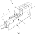
- a detailed view of the mounting rail 30 is in figure 5 shown.
- the rear end 33 of the fastening rail 30 has a support surface, the surface of which largely corresponds to the front surface 97a of the trigger guard 97 .
- the front surface 97a of the trigger guard 97 forms a counter-support surface for the support surface of the mounting rail 30.
- the support surface of the mounting rail 30 is described with reference to FIG Figure 3, Figure 4 and Fig.5 described in more detail.
- the silencer For attachment to the firearm 90, the silencer is pushed completely onto the mounting rail 94 with the attachment rail 30, so that the support surface of the attachment rail 30 rests largely flush on the counter-support surface 97a.
- the silencer is locked on the weapon with the locking rockers 13 arranged at the rear end 33 of the fastening rail 30, so that the silencer 10 cannot become detached from the weapon independently or unintentionally.
- the locking rockers 13 therefore prevent horizontal movement of the silencer 10 against the in 2 shown arrow.
- the locking rockers 13 are designed in such a way that they engage in the trigger guard 97 in the locking state.
- the locking rockers are advantageous 13 are also dimensioned in such a way that they press the support surface of the fastening rail 30 against the counter-support surface 97a of the trigger guard 97 in the locked state.
- two axially protruding wings 35 are also provided at the rear end 33 of the fastening rail 30, which run at a distance from one another and largely parallel to one another.
- the support surface of the fastening rail 30 runs between these two wings 35.
- the distance between the two wings is selected such that it essentially corresponds to the width of the front section (that section on which the counter-support surface 97a is located) of the trigger guard 97.
- the two wings 35 run laterally on the front section of the trigger guard 97. This means that the front section of the trigger guard 97 engages between the two wings 35 in an essentially form-fitting manner.
- the engagement of the trigger guard 97 between the two wings 35 ensures that the silencer 10 oscillates in the horizontal direction P1 after a shot has been fired from the weapon. Furthermore, this further increases the rigidity of the handle.
- a pin or an axial projection 97b can be provided on the front end of the trigger guard 97 or on the counter-support surface 97a of the trigger guard 97, which either engages in a corresponding recess on the support surface of the mounting rail or protrudes below the support surface of the mounting rail.
- the counter-support surface 97a has a substantially concave surface. Accordingly, the corresponding support surface of the fastening rail 30 has a convex surface.
- the counter-support surface 97a it is also possible for the counter-support surface 97a to have an essentially convex surface and for the support surface to have an essentially corresponding concave surface.
- the surfaces of the supporting surface and the counter-supporting surface can be configured as desired. According to the invention, however, it is important that the two surfaces correspond to one another, so that when the silencer is mounted, the support surface of the mounting rail 30 rests on the counter-support surface, preferably largely flush, and the rear end 33 of the mounting rail is prevented from moving downwards relative to the trigger guard.
- FIG. 3 shows the rear end 33 of a fastening device according to the invention in a perspective view.
- the fastening rail 30 of the fastening device has two side walls 31 located at the top.
- the two side walls 31 each have internal longitudinal guides 32 which are designed as guide joints.
- the guide grooves correspond to the mounting rail 94, which is provided on the grip 92 below the barrel/breech 91 on the weapon.
- the silencer can be pushed onto the mounting rail 94 of the firearm with the aid of the longitudinal guides 32 .
- the support surface 36 is also formed on the rear end 33 . Also formed on the rear end 33 is the support surface 36 , which is essentially perpendicular to the longitudinal axis LA of the fastening rail 30 . Furthermore, the support surface 36 runs between two wings 35 formed at the rear end, the wings 35 being arranged essentially perpendicularly to the support surface 36 and running parallel to the longitudinal axis LA of the fastening rail. The two wings 35 are on the support surface 36 to the rear.
- the support surface 36 itself has a convex surface here and is designed in such a way that it corresponds to a concave surface of the end counter-support surface 97a of the trigger guard 97 and rests essentially flush on it when the silencer is mounted.
- the distance between the two wings 35 is chosen so that it essentially corresponds to the width of the front end of the trigger guard 97 .
- the front end of the trigger guard 97 engages between the two wings 3, with a form fit between the wings and the front end of the trigger guard 97 preferably being formed, i.e. the rear end 33 of the fastening rail 30 in the horizontal direction cannot move relative to the trigger guard 97.
- the two side walls 31 with their Longitudinal guides 32 here do not reach as far as the two wings 35 or the support surface 36 , because the mounting rail usually ends in front of the trigger guard 97 .
- FIG. 4 shows the rear end 33 of a fastening device according to the invention in a perspective view and in a sectional view.
- the convex surface of the support surface 36 is clearly visible here 4 shown rear end 33 of the fastening device in 3 rear end shown 33.
- figure 5 shows a specific example of a muffler 10 not according to the invention with a fastening device according to the invention.
- the muffler or the muffler housing 11 and the fastening rail 30 are designed here in one piece or in one piece.
- the silencer and the fastening rail 30 are designed in two parts, ie the silencer or the silencer housing 11 can be releasably connected to the fastening rail 30 .
- Two fastening rails 31 are provided here on the upper side of the fastening rail 30, which run essentially parallel to one another and are provided for fastening the silencer to the mounting rail of the firearm.
- the two fastening rails 31 are designed in such a way that they correspond to an outer profile of a mounting rail 94 of the weapon.
- the mounting rail 30 can have a locking device designed as a locking pin 12 with which the silencer pushed onto the mounting rail of the weapon can be locked on the weapon in order to prevent the silencer from being released from the weapon unintentionally or on its own.
- a locking device designed as a locking pin 12 with which the silencer pushed onto the mounting rail of the weapon can be locked on the weapon in order to prevent the silencer from being released from the weapon unintentionally or on its own.
- the mounting rail 30 At the rear end 33 of the mounting rail 30 are two vertically running, parallel and spaced apart wings 35 that run parallel to the longitudinal axis LA and protrude in the axial direction at the rear end 33 of the mounting rail 30 .
- the distance between the two wings 35 corresponds to the width of a front section of a trigger guard 97 of the weapon to which the silencer is attached.
- the two wings 35 are arranged relative to one another in such a way that the front section of the trigger guard 97 engages between the two wings when the silencer is mounted on the weapon.
- the front end or the front section of the trigger guard 97 engages between the two wings 35 so that the side walls of the trigger guard lie essentially flush on the two inner sides of the wings 95 .
- the support surface 36 running between the two wings 35 is not convex but has a largely flat surface.
- the counter-support surface 97a of the trigger guard 97 is designed accordingly.
- the lower section of the support surface 36 is set back slightly, i.e. between the upper section and the lower section of the support surface 36 a kind of step is formed.
- a correspondingly designed projection of the trigger guard 97 engages in the lower, i.e. set back, section and advantageously rests on the surface of the set back section.
- the step formed between the two sections prevents the rear end 33 of the muffler from being able to fold away downwards when the muffler is installed. If the supporting surface 36 and the counter-supporting surface 97a are convex or concave, the convex and concave design alone prevents such a downward folding away.
- the support surface can also have a recess or indentation into which a projection (e.g. a pin) arranged on the counter-support surface 97a and corresponding to the recess or indentation engages.
- a projection e.g. a pin
- a further mounting rail 34 is provided on the underside of the fastening rail 30, on which additional accessories can be arranged.
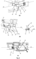
- FIG. 6 shows a locking mechanism or locking device according to the invention of a fastening device according to the invention, the silencer being attached to the firearm here and in figure (a) the locking device in a locking position, in figure (b) the locking device in an unlocking position and in figure (c) the Locking device are shown in a side view.
- the locking device here consists of at least one locking rocker 13, which runs essentially parallel to the longitudinal axis LA of the fastening rail and is arranged at the rear end 33 of the fastening rail.
- the locking rocker 13 is pivoted about a pivot axis 14 on the mounting rail, so that the locking rocker 13 can be brought from a locked position (as shown in figure (a)) into an unlocked position (as shown in figure (b)). In the unlocked position, the silencer can be pulled off the firearm.
- the locking rocker 13 is arranged at the rear end 33 of the mounting rail in such a way that a section of the locking rocker 13 protrudes beyond the rear end 33 of the mounting rail. With the section protruding beyond the rear end 33 of the fastening rail, the silencer is locked on the gun, in that this section can be brought into engagement with the trigger guard 97 of the firearm.
- a pin 17 is provided on the section which protrudes beyond the rear end 33 of the fastening rail and which, in the locked state, goes into the trigger guard 97 intervenes and thus prevents an independent or unintentional release of the silencer from the weapon.
- the engagement of the pin 17 in the trigger guard 97 presses the support surface 36 of the fastening rail against the counter-support surface 97a of the trigger guard 97, so that the support surface 36 rests securely on the counter-support surface 97a.
- the silencer is prevented from moving horizontally along the longitudinal axis LA of the firearm, so that the support surface 36 resting on the counter-support surface 97a together with the lock 13 effectively prevents the silencer from swinging vertically.
- the side of the pin 17 facing the trigger guard 97 has a surface 17a which is designed to slope inwards. That is, the angle ⁇ enclosed by the surface 17a and the longitudinal axis LA2 of the locking rocker 13 is less than 90°, preferably less than 75°, particularly preferably between 40° and 50°. As a result, the inclined surface 17a comes into contact with the trigger guard 97 when the silencer is pushed onto the mounting rail 94 of the firearm. The trigger guard 97 then pivots the pin 17 of the locking rocker 13 outwards and the surface 17a or the pin 17 slides on the trigger guard 97 over.
- the section of the locking rocker 13 that protrudes beyond the rear end 33 of the mounting rail tilts inwards again, so that the pin engages in the trigger guard 97 .
- the locking rocker 13 is then in the locking position.
- the inward tilting can be brought about by a spring element which is assigned to the locking rocker 13 .
- the related to 6 The locking rocker 13 shown has compared to that in figure 5
- the locking pin 12 shown has the advantage that there are no sections of the locking device that protrude laterally beyond the fastening rail while the locking device is in a locking position. the inside figure 5
- the locking pin 12 shown also has the disadvantage that, although the silencer is locked on the firearm, it is not guaranteed that the support surface 36 of the fastening rail will be pressed against the counter-support surface 97a.
- two locking rockers 13 are provided - one on each side wall of the mounting rail.
Landscapes
- Engineering & Computer Science (AREA)
- General Engineering & Computer Science (AREA)
- Clamps And Clips (AREA)
- Toys (AREA)
- Exhaust Silencers (AREA)
- Bedding Items (AREA)
- Thermotherapy And Cooling Therapy Devices (AREA)
- Aiming, Guidance, Guns With A Light Source, Armor, Camouflage, And Targets (AREA)
Description
- Die Erfindung betrifft eine Handfeuerwaffe mit einer Befestigungsvorrichtung zum Befestigen von Waffenzubehör an der Handfeuerwaffe. Das Waffenzubehör ist ein Schalldämpfer.
- Unter dem Begriff "Handfeuerwaffen" werden Faustfeuerwaffen verstanden, etwa Rückstoßladerwaffen, Gasdruckladerwaffen, Pistolen oder dergleichen. Die Erfindung wird am Beispiel einer Handfeuerwaffe beschrieben, obwohl die vorliegende Erfindung nicht hierauf beschränkt ist und auch bei Langwaffen zum Einsatz kommen kann.
- Es ist bekannt, Schusswaffen mit Zubehör zu versehen bzw. Zubehör an Schusswaffen anzubringen. Beispielsweise ist es bekannt, an einer Schusswaffe, beispielsweise an einer Pistole, ein taktisches Licht oder einen Schalldämpfer anzuordnen.
- Solche Schusswaffen sind z.B. aus
US 2012/0124885 A1 ,US 2005/0279004 A1 undWO 2015/001129 A1 bekannt. -
Fig. 1 zeigt einen aus dem Stand der Technik bekannten Schalldämpfer 10, der an einer Waffe 90 befestigt ist, wobei hier lediglich das vordere Ende der Waffe gezeigt ist, d.h. nur Verschluss / Lauf 91 der Waffe 90. - Unterhalb des Verschlusses / Laufes 91 ist an dem Griffstück der Waffe eine Montageschiene vorgesehen, an der der Schalldämpfer befestigt werden kann. Zum Befestigen wird eine Befestigungsschiene 30 des Schalldämpfers 10 auf die Montageschiene der Waffe aufgeschoben. Die Befestigungsschiene 30 ist am hinteren Ende, d.h. an dem der Waffe zugewandten Ende, des Schalldämpfergehäuses 11 angeordnet.
- Diese Art der Befestigung hat den Vorteil, dass der Schalldämpfer 10 unabhängig vom Lauf/Verschluss an der Waffe 90 befestigt werden kann. Nachteilig ist allerdings, dass bei Abgabe eines Schusses der Schalldämpfer 10 in eine Schwingung versetzt wird, insbesondere dann, wenn das Griffstück aus Kunststoff, etwa Polyamid, gefertigt ist. Der Schalldämpfer kann dabei in unterschiedliche Richtungen schwingen, insbesondere horizontal (gezeigt durch den Pfeil P1) und vertikal (gezeigt durch den Pfeil P2). Die Schwingungen vollzieht der Schalldämpfer hierbei unabhängig von der Bewegung des Laufes, sodass unter Umständen die Waffe wieder schussbereit ist, während der Schalldämpfer noch schwingt. Während der Schalldämpfer schwingt verläuft die Mittelachse des Laufes nicht koaxial zur Mittelachse des in dem Schalldämpfer ausgebildeten Schusskanals 20, sodass kein weiterer Schuss abgegeben werden kann, solange der Schalldämpfer schwingt. Dieser Nachteil wirkt sich insbesondere bei halbautomatischen oder vollautomatischen Schusswaffen aus. Bei Repetierwaffen kann dieser Nachteil gegebenenfalls vernachlässigt werden, wenn der Nachladevorgang länger dauert als Schwingen des Schalldämpfers.
- Aufgabe der vorliegenden Erfindung ist es daher, Lösungen bereitzustellen, die die vorstehenden aus dem Stand der Technik bekannten Nachteile zumindest teilweise vermeiden und die ein Schwingen eines an dem Griffstück befestigten Waffenzubehörs, insbesondere Schalldämpfer, weitgehend vermeiden oder zumindest so weit verringert, dass das Abfeuern eines oder mehrerer Schüsse nicht beeinträchtigt wird.
- Diese Aufgabe wird erfindungsgemäß mit einer Handfeuerwaffe gemäss dem Anspruch 1, gelöst. Vorteilhafte Ausgestaltungen und Weiterbildungen der Erfindung sind in den jeweiligen abhängigen Ansprüchen angegeben.
- Bereit gestellt wird demnach eine Befestigungsvorrichtung zum Befestigen von Waffenzubehör, insbesondere Schalldämpfer, an einer Schusswaffe, insbesondere Handfeuerwaffe, wobei die Befestigungsvorrichtung eine Befestigungsschiene zum Befestigen der Befestigungsvorrichtung an einer Montageschiene der Schusswaffe aufweist, wobei am hinteren Ende der Befestigungsschiene eine Stützfläche ausgebildet ist, die zumindest abschnittsweise am vorderen Ende des Abzugsbügels der Schusswaffe aufliegt, wenn die Befestigungsvorrichtung an der Schusswaffe befestigt ist.
- Dadurch wird ein vertikales Schwingen des an der Befestigungsvorrichtung angebrachten Schalldämpfers verhindert.
- Vorteilhaft ist es, wenn die Stützfläche der Befestigungsschiene weitgehend formbündig auf der stirnseitigen Gegenstützfläche aufliegt, wenn die Befestigungsvorrichtung an der Schusswaffe befestigt ist.
- Die Stützfläche der Befestigungsschiene kann eine axiale Aussparung aufweisen, in die ein an dem vorderen Ende des Abzugsbügels angeordneter axialer Vorsprung oder Zapfen vorzugsweise formschlüssig eingreift, wenn die Befestigungsvorrichtung an der Schusswaffe befestigt ist.
- Am hinteren Ende der Befestigungsschiene können zwei zueinander beabstandete axiale Flügel vorgesehen sein, die zumindest abschnittsweise in axialer Richtung an der Stützfläche überstehen.
- Vorteilhaft ist es, wenn der Abstand der beiden Flügel zueinander so gewählt ist, dass er im Wesentlichen der Breite des vorderen Endes des Abzugsbügels entspricht, sodass das vordere Ende des Abzugsbügels zumindest abschnittsweise im Wesentlichen formschlüssig zwischen die beiden Flügel eingreift, wenn die Befestigungsvorrichtung an der Schusswaffe befestigt ist.
- Damit wird ein horizontales Schwingen des an der Befestigungsvorrichtung angebrachten Schalldämpfers verhindert.
- Die Stützfläche kann zwischen den beiden Flügel und senkrecht zu den beiden Flügel verlaufen.
- An der Befestigungsschiene kann eine Verriegelungseinrichtung vorgesehen sein, um die Befestigungsvorrichtung an der Waffe zu arretieren.
- Die Verriegelungseinrichtung kann zumindest eine Verriegelungswippe umfassen, die um eine Schwenkachse schwenkbar an dem hinteren Ende der Befestigungsschiene angeordnet ist, und von einer Verriegelungsposition in eine Entriegelungsposition bringbar ist, wobei die Verriegelungswippe im Wesentlichen parallel zur Längsachse der Befestigungsschiene ausgerichtet ist und im befestigten Zustand der Befestigungsvorrichtung an der Waffe in Eingriff mit dem Abzugsbügel der Waffe bringbar ist, um die Befestigungsvorrichtung an der Waffe zu arretieren.
- Der Schalldämpfer und die Befestigungsvorrichtung sind zweiteilig ausgestaltet.
- Einzelheiten und Merkmale der Erfindung sowie konkrete Ausführungsformen der Erfindung ergeben sich aus der nachfolgenden Beschreibung in Verbindung mit der Zeichnung. Es zeigt:
- Fig. 1
- einen aus dem Stand der Technik bekannten Schalldämpfer der an einer Waffe befestigt ist;
- Fig. 2
- eine erfindungsgemäße Befestigungsvorrichtung zum Befestigen eines Waffenzubehörs (hier: ein Schalldämpfer) an einer Schusswaffe;
- Fig. 3
- das hintere Ende einer erfindungsgemäßen Befestigungsvorrichtung in einer perspektivischen Ansicht;
- Fig. 4
- eine Schnittansicht des in
Fig. 4 gezeigten hinteren Endes einer erfindungsgemäßen Befestigungsvorrichtung; - Fig. 5
- einen erfindungsgemäßen Schalldämpfer; und
- Fig. 6
- einen erfindungsgemäßen Verriegelungsmechanismus einer erfindungsgemäßen Befestigungsvorrichtung.
- Die nachfolgend beschriebene erfindungsgemäße Befestigungsvorrichtung zum Befestigen eines Waffenzubehörs an einer Schusswaffe hat den Vorteil, dass das Waffenzubehör einerseits unabhängig vom Lauf / Verschluss an der Waffe befestigt werden kann und dass andererseits, insbesondere bei einem Schalldämpfer, gewährleistet ist, dass ein Schwingen des Waffenzubehörs, insbesondere nach Abgabe eines Schusses, weitgehend verhindert wird. Ein erfindungsgemäß an einer Schusswaffe befestigter Schalldämpfer ermöglicht dadurch auch den halbautomatischen oder vollautomatischen Betrieb der Schusswaffe. Die Erfindung wird nachfolgend am Beispiel eines Schalldämpfers beschrieben, wobei die Erfindung nicht hierauf beschränkt ist. Erfindungsgemäß können danach auch ein taktisches Licht oder dergleichen befestigt werden.
-
Fig. 2 zeigt eine erfindungsgemäße Befestigungsvorrichtung zum Befestigen eines Waffenzubehörs an einer Schusswaffe 90. Bei dem inFig. 2 gezeigten Beispiel ist das Waffenzubehör ein Schalldämpfer 10. - Der Schalldämpfer 10 besteht hier aus einem Schalldämpfergehäuse 11 und aus einer der hinteren Stirnwand des Schalldämpfergehäuses 11 angeordneten Befestigungsschiene 30. Die hintere Stirnwand des Schalldämpfergehäuses 11 ist hierbei jene Stirnwand die beim Befestigen des Schalldämpfers an der Waffe 90 dem Lauf/Verschluss 91 zugewandt ist.
- Die Befestigungsschiene 30 kann alternativ auch an einer unteren Seitenwand des Schalldämpfers angeordnet sein und sich über die hintere Stirnwand des Schalldämpfers hinaus erstrecken.
- Die Befestigungsschiene 30 und der Schalldämpfer sind zweiteilig ausgestaltet. Die Befestigungsschiene 30 und der daran angeordnete Schalldämpfer werden nachfolgend gemeinsam als Schalldämpfer 10 bezeichnet.
- Die Befestigungsschiene 30 bildet hierbei die erfindungsgemäße Befestigungsvorrichtung.
- An der Unterseite des Griffstückes 92 der Waffe 90 ist eine Montageschiene 94 vorgesehen, auf die die Befestigungsschiene 30 aufgeschoben wird (entlang des in
Fig. 2 gezeigten Pfeiles). Der Lauf und der Verschluss 91 können sich unabhängig von dem an der Befestigungsschiene 30 befestigten Schalldämpfer bewegen. Eine detaillierte Ansicht der Befestigungsschiene 30 ist inFig. 5 gezeigt. - Das hintere Ende 33 der Befestigungsschiene 30 weist eine Stützfläche auf, dessen Oberfläche weitgehend mit der stirnseitigen Oberfläche 97a des Abzugsbügels 97 korrespondiert. Die stirnseitigen Oberfläche 97a des Abzugsbügels 97 bildet hierbei eine Gegenstützfläche für die Stützfläche der Befestigungsschiene 30. Die Stützfläche der Befestigungsschiene 30 wird mit Bezug auf
Fig. 3, Fig. 4 undFig.5 näher beschrieben. - Der Schalldämpfer wird zum Befestigen an der Schusswaffe 90 mit der Befestigungsschiene 30 vollständig auf die Montageschiene 94 geschoben, sodass die Stützfläche der Befestigungsschiene 30 weitgehend formbündig auf der Gegenstützfläche 97a aufliegt. Mit den an dem hinteren Ende 33 der Befestigungsschiene 30 angeordneten Verriegelungswippen 13 wird der Schalldämpfer an der Waffe arretiert, sodass sich der Schalldämpfer 10 nicht selbstständig oder unbeabsichtigt von der Waffe lösen kann. Die Verriegelungswippen 13 verhindern demnach ein horizontales Bewegen des Schalldämpfer 10 entgegen des in
Fig. 2 gezeigten Pfeiles. Die Verriegelungswippen 13 sind hierbei so ausgestaltet, dass sie im Verriegelungszustand in den Abzugsbügel 97 eingreifen. Vorteilhafter Weise sind die Verriegelungswippen 13 zudem so dimensioniert, dass sie im Verriegelungszustand die Stützfläche der Befestigungsschiene 30 gegen die Gegenstützfläche 97a des Abzugsbügels 97 drücken. - Dadurch, dass die Stützfläche der Befestigungsschiene 30 bei an der Waffe montierten Schalldämpfer 10 auf der Gegenstützfläche 97a des Abzugsbügels 97 aufliegt und mit den Verriegelungswippen 13 der Schalldämpfer 10 an der Waffe arretiert wird, wird zuverlässig verhindert, dass der Schalldämpfer in vertikaler Richtung P2 schwingt, nachdem ein Schuss aus der Waffe abgefeuert wurde. Der vordere Abschnitt des Griffstückes 92 kann nicht mehr nach unten schwingen, weil eine Bewegung nach unten durch die auf der Gegenstützfläche 97a des Abzugsbügels 97 aufliegende Befestigungsschiene 30 verhindert wird. Dadurch wird insgesamt auch die Steifigkeit des Griffstückes 92 erhöht.
- Ferner sind an dem hinteren Ende 33 der Befestigungsschiene 30 auch zwei axial überstehende Flügel 35 vorgesehen, die beabstandet zueinander und weitgehend parallel zueinander verlaufen. Zwischen diesen beiden Flügeln 35 verläuft die Stützfläche der Befestigungsschiene 30. Der Abstand der beiden Flügel zueinander ist so gewählt, dass er im Wesentlichen der Breite des stirnseitigen Abschnittes (jener Abschnitt, an dem sich die Gegenstützfläche 97a befindet) des Abzugsbügel 97 entspricht. Nachdem der Schalldämpfer komplett auf die Montageschiene 94 aufgeschoben wurde, verlaufen die beiden Flügel 35 seitlich am stirnseitigen Abschnitt des Abzugsbügels 97. Das bedeutet, dass der stirnseitige Abschnitt des Abzugsbügels 97 im Wesentlichen formschlüssig zwischen die beiden Flügel 35 eingreift. Durch das Eingreifen des Abzugsbügels 97 zwischen die beiden Flügel 35 wird gewährleistet, dass der Schalldämpfer 10 in horizontaler Richtung P1 schwingt, nachdem ein Schuss aus der Waffe abgefeuert wurde. Ferner wird dadurch die Steifigkeit des Griffstückes noch weiter erhöht.
- Durch die vorstehend genannten Maßnahmen wird das Schwingverhalten des Schalldämpfers soweit verbessert, dass auch ein halbautomatischer oder vollautomatischer Betrieb der Schusswaffe ermöglicht wird. Denn durch diese Maßnahmen wird ein Schwingen des Schalldämpfers nach Abgabe eines Schusses nahezu vollständig verhindert.
- Ferner kann an dem vorderen Ende des Abzugsbügels 97 oder an der Gegenstützfläche 97a des Abzugsbügels 97 ein Zapfen oder ein axialer Vorsprung 97b vorgesehen sein, der entweder in eine dazu korrespondierende Aussparung an der Stützfläche der Befestigungsschiene eingreift oder unterhalb der Stützfläche der Befestigungsschiene hineinragt. Dadurch wird eine noch bessere Fixierung des an der Waffe befestigten Schalldämpfers erreicht, insbesondere ein vertikales Bewegen des hinteren Endes 33 der Befestigungsschiene 30 relativ zu dem Abzugsbügel 97 verhindert, sodass einem vertikalen Schwingen des Schalldämpfers 30 noch besser entgegengewirkt wird.
- Bei der in
Fig. 2 gezeigten Ausgestaltung weist die Gegenstützfläche 97a im Wesentlichen eine konkave Oberfläche auf. Dementsprechend weist die dazu korrespondieren Stützfläche der Befestigungsschiene 30 eine konvexe Oberfläche auf. Selbstverständlich ist es auch möglich, dass die Gegenstützfläche 97a im Wesentlichen eine konvexe Oberfläche und die Stützfläche ein im Wesentlichen dazu korrespondierende konkave Oberfläche aufweisen. - Prinzipiell können die Oberflächen der Stützfläche und der Gegenstützfläche beliebig ausgestaltet sein. Erfindungsgemäß wichtig ist allerdings, dass die beiden Oberflächen zueinander korrespondieren, sodass bei montiertem Schalldämpfer die Stützfläche der Befestigungsschiene 30 auf der Gegenstützfläche, vorzugsweise weitgehend formbündig, aufliegt und ein Bewegen des hinteren Endes 33 der Befestigungsschiene relativ zum Abzugsbügel nach unten verhindert wird.
-
Fig. 3 zeigt das hintere Ende 33 einer erfindungsgemäßen Befestigungsvorrichtung in einer perspektivischen Ansicht. - Die Befestigungsschiene 30 der Befestigungsvorrichtung weist zwei obenliegende Seitenwandungen 31 auf. Die beiden Seitenwandungen 31 weisen jeweils innen liegende Längsführungen 32 auf, die als Führungsfugen ausgestaltet sind. Die Führungsfugen korrespondieren mit der Montageschiene 94, die am Griffstück 92 unterhalb des Laufes/Verschlusses 91 an der Waffe vorgesehen ist. Mit Hilfe der Längsführungen 32 kann der Schalldämpfer auf die Montageschiene 94 der Schusswaffe aufgeschoben werden.
- An dem hinteren Ende 33 ist ferner die Stützfläche 36 ausgebildet, die im Wesentlichen senkrecht zur Längsachse LA der Befestigungsschiene 30 steht. Ferner verläuft die Stützfläche 36 zwischen zwei am hinteren Ende ausgebildeten Flügeln 35, wobei die Flügel 35 im Wesentlichen senkrecht zur Stützfläche 36 angeordnet sind und parallel zur Längsachse LA der Befestigungsschiene verlaufen. Die beiden Flügel 35 stehen an der Stützfläche 36 nach hinten über.
- Die Stützfläche 36 selbst weist hier eine konvex verlaufende Oberfläche und ist so ausgestaltet, dass sie mit einer konkav verlaufenden Oberfläche der stirnseitigen Gegenstützfläche 97a des Abzugsbügels 97 korrespondiert und bei montiertem Schalldämpfer im Wesentlichen formbündig auf dieser aufliegt.
- Der Abstand der beiden Flügel 35 zueinander ist so gewählt, dass er im Wesentlichen der Breite der des vorderen Endes des Abzugsbügels 97 entspricht. Bei der Montage des Schalldämpfers kommt das vordere Ende des Abzugsbügels 97 in Eingriff zwischen den beiden Flügeln 3, wobei vorzugsweise ein Formschluss zwischen den Flügeln und dem vorderen Ende des Abzugsbügels 97 gebildet wird, d.h. dass sich das hintere Ende 33 der Befestigungsschiene 30 in horizontaler Richtung nicht relativ zum Abzugsbügel 97 bewegen kann.
- Die beiden Seitenwandungen 31 mit ihren Längsführungen 32 reichen hier nicht bis an die beiden Flügel 35 bzw. an die Stützfläche 36 heran, weil die Montageschiene in der Regel vor dem Abzugsbügel 97 endet.
-
Fig. 4 zeigt das hintere Ende 33 einer erfindungsgemäßen Befestigungsvorrichtung in einer perspektivischen Ansicht und in einer Schnittdarstellung. - Gut erkennbar ist hier die konvex ausgestaltete Oberfläche der Stützfläche 36. Im Übrigen entspricht das in
Fig. 4 gezeigte hintere Ende 33 der Befestigungsvorrichtung dem inFig. 3 gezeigten hinteren Ende 33. -
Fig. 5 zeigt ein konkretes Beispiel eines nicht erfindungsgemäßen Schalldämpfers 10 mit einer erfindungsgemäßen Befestigungsvorrichtung. Der Schalldämpfer bzw. das Schalldämpfergehäuse 11 und die Befestigungsschiene 30 sind hier einteilig bzw. einstückig ausgestaltet. In einer erfindungsgemäßen Ausgestaltung sind der Schalldämpfer und die Befestigungsschiene 30 zweitteilig ausgestaltet, d.h., der Schalldämpfer bzw. das Schalldämpfergehäuse 11 ist lösbar mit der Befestigungsschiene 30 verbindbar. - An der Oberseite der Befestigungsschiene 30 sind hier zwei Befestigungsschienen 31 vorgesehen, die im Wesentlichen parallel zueinander verlaufen und zum Befestigen des Schalldämpfers an der Montageschiene der Schusswaffe vorgesehen sind. Die beiden Befestigungsschienen 31 sind so ausgestaltet, dass sie mit einem Außenprofil einer Montageschiene 94 der Waffe korrespondieren.
- Die Befestigungsschiene 30 kann eine als Verriegelungszapfen 12 ausgebildete Verriegelungseinrichtung aufweisen, mit der der an der Montageschiene der Waffe aufgeschobene Schalldämpfer an der Waffe arretiert werden kann, um ein unbeabsichtigtes oder selbstständiges Lösen des Schalldämpfers von der Waffe zu verhindern. Eine alternative und insbesondere vorteilhafte Ausgestaltung einer Verriegelungseinrichtung ist mit Bezug auf
Fig. 6 beschrieben. - An dem hinteren Ende 33 der Befestigungsschiene 30 sind zwei senkrecht verlaufende, parallel und beabstandet zueinander angeordnete und parallel zur Längsachse LA verlaufende Flügel 35 angeordnet sind, die in axialer Richtung an dem hinteren Ende 33 der Befestigungsschiene 30 überstehen. Der Abstand der beiden Flügel 35 zueinander entspricht hierbei der Breite eines vorderen Abschnittes eines Abzugsbügels 97 der Waffe, an der der Schalldämpfer angebracht wird. Ferner sind die beiden Flügel 35 so relativ zueinander angeordnet, dass der vordere Abschnitt des Abzugsbügels 97 im montierten Zustand des Schalldämpfers an der Waffe zwischen die beiden Flügel eingreift.
- Wird der Schalldämpfer an der Schusswaffe befestigt, greift das vordere Ende bzw. der vordere Abschnitt des Abzugsbügels 97 zwischen die beiden Flügel 35 ein, sodass die Seitenwandungen des Abzugsbügels im Wesentlichen formbündig an den beiden Innenseiten der Flügel 95 aufliegen.
- Bei der in
Fig. 5 gezeigten Ausgestaltung weist die zwischen den beiden Flügeln 35 verlaufende Stützfläche 36 keine konvexe, sondern eine weitgehend ebene Oberfläche auf. Die Gegenstützfläche 97a des Abzugsbügels 97 ist entsprechend ausgestaltet. - Der untere Abschnitt der Stützfläche 36 ist leicht zurückversetzt, d.h. zwischen dem oberen Abschnitt und dem unteren Abschnitt der Stützfläche 36 ist eine Art Stufe ausgebildet. In den unteren, d.h. zurückversetzten Abschnitt greift ein entsprechend ausgestalteter Vorsprung des Abzugsbügels 97 ein und liegt vorteilhafterweise auf der Oberfläche des zurückversetzten Abschnittes auf. Die zwischen den beiden Abschnitten ausgebildete Stufe verhindert, das hintere Ende 33 des Schalldämpfers bei montiertem Schalldämpfer nach unten wegklappen kann. Sind die Stützfläche 36 und die Gegenstützfläche 97a konvex bzw. konkav ausgestaltet, wird bereits durch die konvexe und konkave Ausgestaltung ein solchen wegklappen nach unten verhindert.
- Anstelle eines nach hinten versetzten unteren Abschnittes der Stützfläche 36 kann die Stützfläche auch eine Aussparung bzw. Vertiefung aufweisen, in die ein an der Gegenstützfläche 97a angeordneter und mit der Aussparung bzw. Vertiefung korrespondierender Vorsprung (z.B. ein Zapfen) eingreift.
- An der Unterseite Befestigungsschiene 30 ist eine weitere Montageschiene 34 vorgesehen, an der zusätzliches Zubehör angeordnet werden kann.
-
Fig. 6 zeigt einen erfindungsgemäßen Verriegelungsmechanismus bzw. Verriegelungseinrichtung einer erfindungsgemäßen Befestigungsvorrichtung, wobei der Schalldämpfer hier an der Schusswaffe befestigt ist und wobei in Abbildung (a) die Verriegelungseinrichtung in einer Verriegelungsposition, in Abbildung (b) die Verriegelungseinrichtung in einer Entriegelungsposition und in Abbildung (c) die Verriegelungseinrichtung in einer Seitenansicht gezeigt sind. - Die Verriegelungseinrichtung besteht hier aus zumindest einer Verriegelungswippe 13, die im Wesentlichen parallel zur Längsachse LA der Befestigungsschiene verläuft und an dem hinteren Ende 33 der Befestigungsschiene angeordnet ist. Die Verriegelungswippe 13 ist um eine Schwenkachse 14 schwenkbar an der Befestigungsschiene gelagert, sodass die Verriegelungswippe 13 von einer Verriegelungsposition (wie in Abbildung (a) gezeigt) in eine Entriegelungsposition (wie in Abbildung (b) gezeigt) bringbar ist. In der Entriegelungsposition kann der Schalldämpfer von der Schusswaffe abgezogen werden.
- Die Verriegelungswippe 13 ist an dem hinteren Ende 33 der Befestigungsschiene angeordnet, und zwar so, dass ein Abschnitt der Verriegelungswippe 13 über das hintere Ende 33 der Befestigungsschiene hinausragt. Mit dem über das hintere Ende 33 der Befestigungsschiene hinausragenden Abschnitt wird der Schalldämpfer an der Schussaffe arretiert, indem dieser Abschnitt in Eingriff mit dem Abzugsbügel 97 der Schusswaffe bringbar ist. An dem über das hintere Ende 33 der Befestigungsschiene hinausragenden Abschnitt ist ein Zapfen 17 vorgesehen, der im Verriegelungszustand in den Abzugsbügel 97 eingreift und so ein selbständiges oder ungewolltes Lösen des Schalldämpfers von der Waffe verhindert. Ferner wird durch das Eingreifen des Zapfens 17 in den Abzugsbügel 97 die Stützfläche 36 der Befestigungsschiene gegen die Gegenstützfläche 97a des Abzugsbügels 97 gedrückt, sodass die Stützfläche 36 sicher auf der Gegenstützfläche 97a aufliegt. Im Verriegelungszustand wird ein horizontales Bewegen des Schalldämpfers entlang der Längsachse LA der Schusswaffe verhindert, sodass die auf der Gegenstützfläche 97a aufliegende Stützfläche 36 zusammen mit der Verriegelung 13 ein vertikales Schwingen des Schalldämpfers effektiv verhindert.
- Die dem Abzugsbügel 97 zugewandte Seite des Zapfens 17 weist eine Oberfläche 17a auf, die nach innen hin abfallend ausgestaltet ist. D.h., der durch die Oberfläche 17a und die Längsachse LA2 der Verriegelungswippe 13 eingeschlossene Winkel α ist kleiner als 90°, vorzugsweise kleiner als 75°, besonders bevorzugt etwa zwischen 40° und 50°. Dadurch gelangt die schräge Oberfläche 17a beim Aufschieben des Schalldämpfers auf die Montageschiene 94 der Schusswaffe in Anschlag mit dem Abzugsbügel 97. Der Abzugsbügel 97 schwenkt dann den Zapfen 17 der Verriegelungswippe 13 nach außen und die Oberfläche 17a bzw. der Zapfen 17 gleitet an dem Abzugsbügel 97 vorbei. Nach dem vollständigen Aufschieben des Schalldämpfers auf die Montageschiene 94 der Schusswaffe kippt der über das hintere Ende 33 der Befestigungsschiene hinausragende Abschnitt der Verriegelungswippe 13 wieder nach innen, sodass der Zapfen in den Abzugsbügel 97 eingreift. Die Verriegelungswippe 13 ist dann in der Verriegelungsposition. Das Nachinnenkippen kann von einem Federelement bewirkt werden, das der Verriegelungswippe 13 zugeordnet ist.
- Um die Verriegelungswippe 13 in die Entriegelungsposition zu bringen muss lediglich der nicht über das hintere Ende 33 der Befestigungsschiene überstehende Abschnitt nach innen gedrückt werden. Der über das hintere Ende 33 der Befestigungsschiene überstehende Abschnitt bzw. der zapfen 17 wird dann um die Schwenkachse 14 nach außen geschwenkt, sodass der Zapfen 17 nicht mehr in den Abzugsbügel 97 eingreift. Der Schalldämpfer kann dann einfach von der Schusswaffe abgezogen werden.
- Damit werden einerseits ein besonders einfaches Arretieren und ein einfaches Lösen der Arretierung ermöglicht. Andererseits wird die Stützfläche 36 der Befestigungsschiene gegen die Gegenstützfläche 97a gedrückt.
- Die mit Bezug auf
Fig. 6 gezeigte Verriegelungswippe 13 hat gegenüber dem inFig. 5 gezeigten Verriegelungszapfen 12 den Vorteil, dass keinerlei seitlich über die Befestigungsschiene überstehende Abschnitte der Verriegelungseinrichtung vorhanden sind, während sich die Verriegelungseinrichtung in einer Verrieglungsposition befindet. Der inFig. 5 gezeigten Verriegelungszapfen 12 hat ferner den Nachteil, dass zwar der Schalldämpfer an der Schusswaffe arretiert wird, es aber nicht gewährleistet ist, dass die Stützfläche 36 der Befestigungsschiene gegen die Gegenstützfläche 97a gedrückt wird. - Vorteilhafterweise sind zwei Verriegelungswippen 13 vorgesehen - eine an jeder Seitenwandung der Befestigungsschiene.
-
- 10
- Waffenzubehör, insbesondere Schalldämpfer (oder taktisches Licht o.ä.)
- 20
- Schusskanal
- 11
- Schalldämpfergehäuse
- 12
- Verriegelungszapfen
- 13
- Verriegelungswippe
- 14
- Dreh- bzw. Schwenkachse der Verriegelungswippe 13
- 17
- Zapfen der Verriegelungswippe 13
- 17a
- schräge Oberfläche des Zapfens 17
- 30
- Befestigungsschiene
- 31
- Seitenwandung der Befestigungsschiene 30
- 32
- Längsführung (z.B. Führungsfugen) der Befestigungsschiene 30
- 33
- hinteres Ende der Befestigungsschiene 30
- 34
- Montageschiene an der Unterseite des Schalldämpfers 10
- 35
- Flügel am hinteren Ende 33 der Befestigungsschiene 30
- 36
- Stützfläche zwischen den Flügeln 35
- 90
- Waffe
- 91
- Verschluss / Lauf
- 92
- Griffstück der Waffe 90
- 94
- Montageschiene an der Unterseite der Waffe 90 bzw. an der Unterseite des Griffstückes 92 im Bereich der Verschlusses 91
- 97
- Abzugsbügel der Waffe 90
- 97a
- vorderes Ende des Abzugsbügels 97 bzw. stirnseitige Gegenstützfläche des Abzugsbügels 97
- 97b
- Zapfen / Vorsprung an der stirnseitigen Gegenstützfläche 97a
- LA
- Längsachse der Waffe 90 bzw. des Schalldämpfers 10
- LA2
- Längsachse der der Verriegelungswippe 13
- P1, P2
- Schwingrichtung des Schalldämpfers 10 (Stand der Technik)
- α
- Winkel zwischen der Längsachse LA2 und der schrägen Oberfläche 17a
Claims (8)
- Handfeuerwaffe mit einer Befestigungsvorrichtung zum Befestigen eines Schalldämpfers (10) an der Handfeuerwaffe (90), wobei die Befestigungsvorrichtung eine Befestigungsschiene (30) zum Befestigen der Befestigungsvorrichtung an einer Montageschiene (94) der Handfeuerwaffe aufweist,
dadurch gekennzeichnet, dassam hinteren Ende (33) der Befestigungsschiene (30) eine Stützfläche (36) ausgebildet ist, die zumindest abschnittsweise am vorderen Ende (97a) des Abzugsbügels (97) der Handfeuerwaffe (90) aufliegt, wenn die Befestigungsvorrichtung an der Handfeuerwaffe befestigt ist,wobei- die dem Abzugsbügel (97) zugewandte Oberfläche der Stützfläche (36) eine konvexe Wölbung aufweist,- das vordere Ende (97a) des Abzugsbügels (97) als stirnseitige Gegenstützfläche ausgebildet ist, die zumindest abschnittsweise mit der konvex gewölbten Stützfläche (36) korrespondiert, und- der Schalldämpfer und die Befestigungsvorrichtung zweiteilig ausgestaltet sind. - Handfeuerwaffe nach dem vorhergehenden Anspruch, wobei die Stützfläche (36) der Befestigungsschiene (30) weitgehend formbündig auf der stirnseitigen Gegenstützfläche (97a) aufliegt, wenn die Befestigungsvorrichtung an der Handfeuerwaffe befestigt ist.
- Handfeuerwaffe nach einem der vorhergehenden Ansprüche, wobei die Stützfläche (36) der Befestigungsschiene (30) eine axiale Aussparung aufweist, in die ein an dem vorderen Ende (97a) des Abzugsbügels (97) angeordneter axialer Vorsprung oder Zapfen (97b) vorzugsweise formschlüssig eingreift, wenn die Befestigungsvorrichtung an der Handfeuerwaffe befestigt ist.
- Handfeuerwaffe nach einem der vorhergehenden Ansprüche, wobei am hinteren Ende (33) der Befestigungsschiene (30) zwei zueinander beabstandete axiale Flügel (35) vorgesehen sind, die zumindest abschnittsweise in axialer Richtung an der Stützfläche (36) überstehen.
- Handfeuerwaffe nach dem vorhergehenden Anspruch, wobei der Abstand der beiden Flügel (35) zueinander so gewählt ist, dass er im Wesentlichen der Breite des vorderen Endes des Abzugsbügels (97) entspricht, sodass das vordere Ende des Abzugsbügels (97) zumindest abschnittsweise im Wesentlichen formschlüssig zwischen die beiden Flügel (35) eingreift, wenn die Befestigungsvorrichtung an der Handfeuerwaffe befestigt ist.
- Handfeuerwaffe nach einem der beiden vorhergehenden Ansprüche, wobei die Stützfläche (36) zwischen den beiden Flügel (35) und senkrecht zu den beiden Flügel (35) verläuft.
- Handfeuerwaffe nach einem der vorhergehenden Ansprüche, wobei an der Befestigungsschiene (30) eine Verriegelungseinrichtung (12; 13) vorgesehen ist, um die Befestigungsvorrichtung an der Handfeuerwaffe zu arretieren.
- Handfeuerwaffe nach dem vorhergehenden Anspruch, wobei die Verriegelungseinrichtung zumindest eine Verriegelungswippe (13) umfasst, die um eine Schwenkachse (14) schwenkbar an dem hinteren Ende (33) der Befestigungsschiene (30) angeordnet ist, und von einer Verriegelungsposition in eine Entriegelungsposition bringbar ist, wobei die Verriegelungswippe (13) im Wesentlichen parallel zur Längsachse (LA) der Befestigungsschiene (30) ausgerichtet ist und im befestigten Zustand der Befestigungsvorrichtung an der Handfeuerwaffe in Eingriff mit dem Abzugsbügel (97) der Handfeuerwaffe (90) bringbar ist, um die Befestigungsvorrichtung an der Handfeuerwaffe zu arretieren.
Priority Applications (1)
| Application Number | Priority Date | Filing Date | Title |
|---|---|---|---|
| HRP20200350TT HRP20200350T1 (hr) | 2015-12-17 | 2016-10-12 | Osobno vatreno oružje |
Applications Claiming Priority (2)
| Application Number | Priority Date | Filing Date | Title |
|---|---|---|---|
| DE102015122091.1A DE102015122091A1 (de) | 2015-12-17 | 2015-12-17 | Befestigungsvorrichtung für Waffenzubehör |
| PCT/EP2016/074431 WO2017102132A1 (de) | 2015-12-17 | 2016-10-12 | Befestigungsvorrichtung für waffenzubehör |
Publications (3)
| Publication Number | Publication Date |
|---|---|
| EP3390953A1 EP3390953A1 (de) | 2018-10-24 |
| EP3390953B1 EP3390953B1 (de) | 2019-12-18 |
| EP3390953B2 true EP3390953B2 (de) | 2023-08-16 |
Family
ID=57124043
Family Applications (1)
| Application Number | Title | Priority Date | Filing Date |
|---|---|---|---|
| EP16779134.2A Active EP3390953B2 (de) | 2015-12-17 | 2016-10-12 | Handfeuerwaffe |
Country Status (5)
| Country | Link |
|---|---|
| US (1) | US10890400B2 (de) |
| EP (1) | EP3390953B2 (de) |
| DE (1) | DE102015122091A1 (de) |
| HR (1) | HRP20200350T1 (de) |
| WO (1) | WO2017102132A1 (de) |
Families Citing this family (18)
| Publication number | Priority date | Publication date | Assignee | Title |
|---|---|---|---|---|
| DE102017103010A1 (de) * | 2017-02-15 | 2018-08-16 | Dieter Christandl | Schalldämpfer für Handfeuerwaffe |
| USD842419S1 (en) | 2017-08-09 | 2019-03-05 | Energetic Armament, LLC | Gun suppressor |
| EP3749913B1 (de) | 2018-02-05 | 2023-07-26 | Sturm, Ruger & Company, Inc. | Integral schallgedämpfte handfeuerwaffe |
| DE102018107418B4 (de) * | 2018-03-28 | 2021-01-28 | Oliver Fischer | Schalldämpfer für eine Handfeuerwaffe |
| US11530890B2 (en) | 2018-12-10 | 2022-12-20 | Maxim Defense Industries, LLC | Apparatus and method for regulating firearm discharge gases and mounting a component to a firearm |
| USD1020965S1 (en) | 2021-10-25 | 2024-04-02 | Maxim Defense Industries, LLC | Combined firearm suppressor core and tube |
| USD1069018S1 (en) | 2021-10-25 | 2025-04-01 | Maxim Defense Industries, LLC | Firearm suppressor core |
| US12449219B2 (en) | 2021-08-30 | 2025-10-21 | Maxim Defense Industries, LLC | Firearm suppressor and self-torquing feature |
| USD1036611S1 (en) | 2022-01-14 | 2024-07-23 | Maxim Defense Industries, LLC | Combined firearm suppressor core, mount body, and tube |
| USD1057070S1 (en) | 2022-01-14 | 2025-01-07 | Maxim Defense Industries, LLC | Firearm suppressor core |
| USD1035816S1 (en) | 2022-01-14 | 2024-07-16 | Maxim Defense Industries, LLC | Combined firearm suppressor core, mount body, tube, and spring |
| USD1080791S1 (en) | 2022-01-14 | 2025-06-24 | Maxim Defense Industries, LLC | Firearm suppressor core |
| US12298096B2 (en) | 2022-01-14 | 2025-05-13 | Maxim Defense Industries, LLC | Firearm suppressor assembly, and apparatus and method for audible signature reduction of a firearm |
| US12169109B2 (en) * | 2022-02-18 | 2024-12-17 | Hs Produkt D.O.O. | Firearm accessories and attachment systems |
| WO2024096832A1 (en) * | 2022-11-02 | 2024-05-10 | Ulucam Onur | Gun silencer with drilling handle or hollow handle with quick tool apparatus |
| US20250075994A1 (en) * | 2023-08-31 | 2025-03-06 | Impact, Inc. | Firearm accessory system and device |
| US12498192B2 (en) | 2024-01-23 | 2025-12-16 | Oliver Fischer | Silencer for a handgun, with a displaceable attaching rail |
| DE102024115542A1 (de) * | 2024-06-04 | 2025-12-04 | Dieter Christandl | Befestigungsvorrichtung für Schalldämpfer |
Citations (8)
| Publication number | Priority date | Publication date | Assignee | Title |
|---|---|---|---|---|
| US6393752B1 (en) † | 1999-10-04 | 2002-05-28 | Keith P. Oliver | Mounting device of pistol laser site |
| WO2003089868A1 (en) † | 2002-02-25 | 2003-10-30 | Mekanova Development Kb | A gun accessory mounting device |
| US20070028502A1 (en) † | 2004-06-02 | 2007-02-08 | Woodmansee John W Iii | Mounting assembly and methods of using same |
| WO2008119098A1 (de) † | 2007-04-03 | 2008-10-09 | Gaston Glock | Befestigungsschiene für feuerwaffe |
| US8683731B2 (en) † | 2011-09-26 | 2014-04-01 | Lasermax, Inc. | Firearm laser sight alignment assembly |
| DE102013107115A1 (de) † | 2013-02-22 | 2014-08-28 | Oliver Fischer | Schalldämpfer |
| CN204788047U (zh) † | 2015-07-07 | 2015-11-18 | 丹东依镭社电子科技有限公司 | 一种92式手枪的支架系统 |
| US20170023324A1 (en) † | 2015-07-26 | 2017-01-26 | Ye Xu | Multifunctional and Detachable Trigger Safety Device for a Firearm |
Family Cites Families (10)
| Publication number | Priority date | Publication date | Assignee | Title |
|---|---|---|---|---|
| IT1194990B (it) * | 1981-09-30 | 1988-09-28 | Beretta Armi Spa | Dispositivo di fissaggio del silenziatore ad armi portatili |
| AT396984B (de) * | 1987-10-19 | 1994-01-25 | Unipatent Holding S A | Kompensator für handfeuerwaffen |
| CH680015A5 (de) | 1990-01-26 | 1992-05-29 | Sig Schweiz Industrieges | |
| US5179235A (en) * | 1991-09-10 | 1993-01-12 | Toole Ronald L | Pistol sighting device |
| US5208826A (en) * | 1992-01-06 | 1993-05-04 | Applied Laser Systems | Aimable laser module mount |
| US6185854B1 (en) | 1998-07-02 | 2001-02-13 | Insight Technology, Incorporated | Auxiliary device for a weapon and attachment thereof |
| US7395627B2 (en) * | 2006-03-29 | 2008-07-08 | Surefire, Llc | Accessory mount for a firearm |
| US8915009B2 (en) * | 2010-11-16 | 2014-12-23 | Crimson Trace Corporation | Modular sighting and lighting system for handguns |
| WO2015001129A1 (de) * | 2013-07-05 | 2015-01-08 | STEINDL, Andreas | Schalldämpfer |
| US9488437B1 (en) * | 2014-05-02 | 2016-11-08 | Gideon Schnog | Firearm mounted video camera system |
-
2015
- 2015-12-17 DE DE102015122091.1A patent/DE102015122091A1/de active Pending
-
2016
- 2016-10-12 WO PCT/EP2016/074431 patent/WO2017102132A1/de not_active Ceased
- 2016-10-12 HR HRP20200350TT patent/HRP20200350T1/hr unknown
- 2016-10-12 EP EP16779134.2A patent/EP3390953B2/de active Active
-
2018
- 2018-06-14 US US16/008,680 patent/US10890400B2/en active Active
Patent Citations (8)
| Publication number | Priority date | Publication date | Assignee | Title |
|---|---|---|---|---|
| US6393752B1 (en) † | 1999-10-04 | 2002-05-28 | Keith P. Oliver | Mounting device of pistol laser site |
| WO2003089868A1 (en) † | 2002-02-25 | 2003-10-30 | Mekanova Development Kb | A gun accessory mounting device |
| US20070028502A1 (en) † | 2004-06-02 | 2007-02-08 | Woodmansee John W Iii | Mounting assembly and methods of using same |
| WO2008119098A1 (de) † | 2007-04-03 | 2008-10-09 | Gaston Glock | Befestigungsschiene für feuerwaffe |
| US8683731B2 (en) † | 2011-09-26 | 2014-04-01 | Lasermax, Inc. | Firearm laser sight alignment assembly |
| DE102013107115A1 (de) † | 2013-02-22 | 2014-08-28 | Oliver Fischer | Schalldämpfer |
| CN204788047U (zh) † | 2015-07-07 | 2015-11-18 | 丹东依镭社电子科技有限公司 | 一种92式手枪的支架系统 |
| US20170023324A1 (en) † | 2015-07-26 | 2017-01-26 | Ye Xu | Multifunctional and Detachable Trigger Safety Device for a Firearm |
Non-Patent Citations (1)
| Title |
|---|
| CN 204788047 U. Übersetzung † |
Also Published As
| Publication number | Publication date |
|---|---|
| HRP20200350T1 (hr) | 2020-10-02 |
| WO2017102132A1 (de) | 2017-06-22 |
| DE102015122091A1 (de) | 2017-06-22 |
| US10890400B2 (en) | 2021-01-12 |
| EP3390953A1 (de) | 2018-10-24 |
| US20180292161A1 (en) | 2018-10-11 |
| EP3390953B1 (de) | 2019-12-18 |
Similar Documents
| Publication | Publication Date | Title |
|---|---|---|
| EP3390953B2 (de) | Handfeuerwaffe | |
| EP3390952B1 (de) | Schalldämpfer und befestigungsvorrichtung dafür | |
| DE1453908C3 (de) | Verschlußführung für eine Feuerwaffe | |
| DE102018132756B4 (de) | Umrüstsatz für eine Kurzwaffe | |
| DE102006006034B3 (de) | Handfeuerwaffe mit Durchladehebel | |
| DE2349339B2 (de) | Gasdruckladeeinrichtung für eine Selbstladewaffe | |
| EP1924815B1 (de) | Gaszylinderbauteil und handfeuerwaffe | |
| DE19722464A1 (de) | Gehäuse für eine Handfeuerwaffe | |
| DE102004021952B3 (de) | Selbstlade-Handfeuerwaffe mit beschleunigtem Verschlußträger | |
| WO2002099353A1 (de) | Kurzrepetiergewehr | |
| DE102009057864B4 (de) | Handfeuerwaffe | |
| DE102015017246B3 (de) | Befestigungsvorrichtung für Schalldämpfer | |
| EP3583373B1 (de) | Schalldämpfer für handfeuerwaffe | |
| EP4028708B1 (de) | Schlosssystem | |
| EP1626243B1 (de) | Handfeuerwaffe für sportliches Schiessen | |
| WO2008119098A1 (de) | Befestigungsschiene für feuerwaffe | |
| EP1559984B1 (de) | Handfeuerwaffe | |
| EP4242573A1 (de) | Selbstladepistole | |
| DE102024115542A1 (de) | Befestigungsvorrichtung für Schalldämpfer | |
| EP3730893B1 (de) | Lagereinheit zur lagerung einer verschlusseinheit und eines laufs einer schusswaffe, insbesondere einer sportwaffe | |
| EP3775751B1 (de) | Schalldämpfer für eine handfeuerwaffe | |
| EP1955003B1 (de) | Waffe mit wechselrohr | |
| WO2001022023A1 (de) | Gewehr mit einem gelenkmechanismus zwischen dem schaft und dem waffengehäuse | |
| DE102019135856B4 (de) | Schusswaffe | |
| DE1951549C2 (de) | Lagerung für eine Handfeuerwaffe |
Legal Events
| Date | Code | Title | Description |
|---|---|---|---|
| STAA | Information on the status of an ep patent application or granted ep patent |
Free format text: STATUS: THE INTERNATIONAL PUBLICATION HAS BEEN MADE |
|
| PUAI | Public reference made under article 153(3) epc to a published international application that has entered the european phase |
Free format text: ORIGINAL CODE: 0009012 |
|
| STAA | Information on the status of an ep patent application or granted ep patent |
Free format text: STATUS: REQUEST FOR EXAMINATION WAS MADE |
|
| 17P | Request for examination filed |
Effective date: 20180717 |
|
| AK | Designated contracting states |
Kind code of ref document: A1 Designated state(s): AL AT BE BG CH CY CZ DE DK EE ES FI FR GB GR HR HU IE IS IT LI LT LU LV MC MK MT NL NO PL PT RO RS SE SI SK SM TR |
|
| AX | Request for extension of the european patent |
Extension state: BA ME |
|
| DAV | Request for validation of the european patent (deleted) | ||
| DAX | Request for extension of the european patent (deleted) | ||
| GRAJ | Information related to disapproval of communication of intention to grant by the applicant or resumption of examination proceedings by the epo deleted |
Free format text: ORIGINAL CODE: EPIDOSDIGR1 |
|
| GRAP | Despatch of communication of intention to grant a patent |
Free format text: ORIGINAL CODE: EPIDOSNIGR1 |
|
| GRAP | Despatch of communication of intention to grant a patent |
Free format text: ORIGINAL CODE: EPIDOSNIGR1 |
|
| STAA | Information on the status of an ep patent application or granted ep patent |
Free format text: STATUS: GRANT OF PATENT IS INTENDED |
|
| INTG | Intention to grant announced |
Effective date: 20190702 |
|
| GRAS | Grant fee paid |
Free format text: ORIGINAL CODE: EPIDOSNIGR3 |
|
| GRAA | (expected) grant |
Free format text: ORIGINAL CODE: 0009210 |
|
| STAA | Information on the status of an ep patent application or granted ep patent |
Free format text: STATUS: THE PATENT HAS BEEN GRANTED |
|
| AK | Designated contracting states |
Kind code of ref document: B1 Designated state(s): AL AT BE BG CH CY CZ DE DK EE ES FI FR GB GR HR HU IE IS IT LI LT LU LV MC MK MT NL NO PL PT RO RS SE SI SK SM TR |
|
| REG | Reference to a national code |
Ref country code: CH Ref legal event code: EP |
|
| REG | Reference to a national code |
Ref country code: DE Ref legal event code: R096 Ref document number: 502016008091 Country of ref document: DE |
|
| REG | Reference to a national code |
Ref country code: IE Ref legal event code: FG4D Free format text: LANGUAGE OF EP DOCUMENT: GERMAN |
|
| REG | Reference to a national code |
Ref country code: AT Ref legal event code: REF Ref document number: 1215076 Country of ref document: AT Kind code of ref document: T Effective date: 20200115 |
|
| REG | Reference to a national code |
Ref country code: HR Ref legal event code: TUEP Ref document number: P20200350T Country of ref document: HR |
|
| REG | Reference to a national code |
Ref country code: NL Ref legal event code: FP |
|
| PG25 | Lapsed in a contracting state [announced via postgrant information from national office to epo] |
Ref country code: SE Free format text: LAPSE BECAUSE OF FAILURE TO SUBMIT A TRANSLATION OF THE DESCRIPTION OR TO PAY THE FEE WITHIN THE PRESCRIBED TIME-LIMIT Effective date: 20191218 Ref country code: LV Free format text: LAPSE BECAUSE OF FAILURE TO SUBMIT A TRANSLATION OF THE DESCRIPTION OR TO PAY THE FEE WITHIN THE PRESCRIBED TIME-LIMIT Effective date: 20191218 Ref country code: FI Free format text: LAPSE BECAUSE OF FAILURE TO SUBMIT A TRANSLATION OF THE DESCRIPTION OR TO PAY THE FEE WITHIN THE PRESCRIBED TIME-LIMIT Effective date: 20191218 Ref country code: BG Free format text: LAPSE BECAUSE OF FAILURE TO SUBMIT A TRANSLATION OF THE DESCRIPTION OR TO PAY THE FEE WITHIN THE PRESCRIBED TIME-LIMIT Effective date: 20200318 Ref country code: GR Free format text: LAPSE BECAUSE OF FAILURE TO SUBMIT A TRANSLATION OF THE DESCRIPTION OR TO PAY THE FEE WITHIN THE PRESCRIBED TIME-LIMIT Effective date: 20200319 Ref country code: NO Free format text: LAPSE BECAUSE OF FAILURE TO SUBMIT A TRANSLATION OF THE DESCRIPTION OR TO PAY THE FEE WITHIN THE PRESCRIBED TIME-LIMIT Effective date: 20200318 Ref country code: LT Free format text: LAPSE BECAUSE OF FAILURE TO SUBMIT A TRANSLATION OF THE DESCRIPTION OR TO PAY THE FEE WITHIN THE PRESCRIBED TIME-LIMIT Effective date: 20191218 |
|
| REG | Reference to a national code |
Ref country code: LT Ref legal event code: MG4D |
|
| PG25 | Lapsed in a contracting state [announced via postgrant information from national office to epo] |
Ref country code: RS Free format text: LAPSE BECAUSE OF FAILURE TO SUBMIT A TRANSLATION OF THE DESCRIPTION OR TO PAY THE FEE WITHIN THE PRESCRIBED TIME-LIMIT Effective date: 20191218 |
|
| PG25 | Lapsed in a contracting state [announced via postgrant information from national office to epo] |
Ref country code: AL Free format text: LAPSE BECAUSE OF FAILURE TO SUBMIT A TRANSLATION OF THE DESCRIPTION OR TO PAY THE FEE WITHIN THE PRESCRIBED TIME-LIMIT Effective date: 20191218 |
|
| PG25 | Lapsed in a contracting state [announced via postgrant information from national office to epo] |
Ref country code: RO Free format text: LAPSE BECAUSE OF FAILURE TO SUBMIT A TRANSLATION OF THE DESCRIPTION OR TO PAY THE FEE WITHIN THE PRESCRIBED TIME-LIMIT Effective date: 20191218 Ref country code: PT Free format text: LAPSE BECAUSE OF FAILURE TO SUBMIT A TRANSLATION OF THE DESCRIPTION OR TO PAY THE FEE WITHIN THE PRESCRIBED TIME-LIMIT Effective date: 20200513 Ref country code: EE Free format text: LAPSE BECAUSE OF FAILURE TO SUBMIT A TRANSLATION OF THE DESCRIPTION OR TO PAY THE FEE WITHIN THE PRESCRIBED TIME-LIMIT Effective date: 20191218 |
|
| PG25 | Lapsed in a contracting state [announced via postgrant information from national office to epo] |
Ref country code: SM Free format text: LAPSE BECAUSE OF FAILURE TO SUBMIT A TRANSLATION OF THE DESCRIPTION OR TO PAY THE FEE WITHIN THE PRESCRIBED TIME-LIMIT Effective date: 20191218 Ref country code: IS Free format text: LAPSE BECAUSE OF FAILURE TO SUBMIT A TRANSLATION OF THE DESCRIPTION OR TO PAY THE FEE WITHIN THE PRESCRIBED TIME-LIMIT Effective date: 20200418 Ref country code: SK Free format text: LAPSE BECAUSE OF FAILURE TO SUBMIT A TRANSLATION OF THE DESCRIPTION OR TO PAY THE FEE WITHIN THE PRESCRIBED TIME-LIMIT Effective date: 20191218 |
|
| REG | Reference to a national code |
Ref country code: DE Ref legal event code: R026 Ref document number: 502016008091 Country of ref document: DE |
|
| PLBI | Opposition filed |
Free format text: ORIGINAL CODE: 0009260 |
|
| REG | Reference to a national code |
Ref country code: HR Ref legal event code: T1PR Ref document number: P20200350 Country of ref document: HR |
|
| 26 | Opposition filed |
Opponent name: GLOCK TECHNOLOGY GMBH Effective date: 20200915 |
|
| PG25 | Lapsed in a contracting state [announced via postgrant information from national office to epo] |
Ref country code: DK Free format text: LAPSE BECAUSE OF FAILURE TO SUBMIT A TRANSLATION OF THE DESCRIPTION OR TO PAY THE FEE WITHIN THE PRESCRIBED TIME-LIMIT Effective date: 20191218 Ref country code: ES Free format text: LAPSE BECAUSE OF FAILURE TO SUBMIT A TRANSLATION OF THE DESCRIPTION OR TO PAY THE FEE WITHIN THE PRESCRIBED TIME-LIMIT Effective date: 20191218 |
|
| REG | Reference to a national code |
Ref country code: HR Ref legal event code: ODRP Ref document number: P20200350 Country of ref document: HR Payment date: 20201006 Year of fee payment: 5 |
|
| PLAX | Notice of opposition and request to file observation + time limit sent |
Free format text: ORIGINAL CODE: EPIDOSNOBS2 |
|
| PG25 | Lapsed in a contracting state [announced via postgrant information from national office to epo] |
Ref country code: SI Free format text: LAPSE BECAUSE OF FAILURE TO SUBMIT A TRANSLATION OF THE DESCRIPTION OR TO PAY THE FEE WITHIN THE PRESCRIBED TIME-LIMIT Effective date: 20191218 |
|
| PG25 | Lapsed in a contracting state [announced via postgrant information from national office to epo] |
Ref country code: PL Free format text: LAPSE BECAUSE OF FAILURE TO SUBMIT A TRANSLATION OF THE DESCRIPTION OR TO PAY THE FEE WITHIN THE PRESCRIBED TIME-LIMIT Effective date: 20191218 |
|
| PLBB | Reply of patent proprietor to notice(s) of opposition received |
Free format text: ORIGINAL CODE: EPIDOSNOBS3 |
|
| REG | Reference to a national code |
Ref country code: HR Ref legal event code: ODRP Ref document number: P20200350 Country of ref document: HR Payment date: 20210930 Year of fee payment: 6 |
|
| PGFP | Annual fee paid to national office [announced via postgrant information from national office to epo] |
Ref country code: MC Payment date: 20211020 Year of fee payment: 6 Ref country code: LU Payment date: 20211021 Year of fee payment: 6 Ref country code: IE Payment date: 20211021 Year of fee payment: 6 |
|
| PG25 | Lapsed in a contracting state [announced via postgrant information from national office to epo] |
Ref country code: TR Free format text: LAPSE BECAUSE OF FAILURE TO SUBMIT A TRANSLATION OF THE DESCRIPTION OR TO PAY THE FEE WITHIN THE PRESCRIBED TIME-LIMIT Effective date: 20191218 Ref country code: MT Free format text: LAPSE BECAUSE OF FAILURE TO SUBMIT A TRANSLATION OF THE DESCRIPTION OR TO PAY THE FEE WITHIN THE PRESCRIBED TIME-LIMIT Effective date: 20191218 Ref country code: CY Free format text: LAPSE BECAUSE OF FAILURE TO SUBMIT A TRANSLATION OF THE DESCRIPTION OR TO PAY THE FEE WITHIN THE PRESCRIBED TIME-LIMIT Effective date: 20191218 |
|
| PG25 | Lapsed in a contracting state [announced via postgrant information from national office to epo] |
Ref country code: MK Free format text: LAPSE BECAUSE OF FAILURE TO SUBMIT A TRANSLATION OF THE DESCRIPTION OR TO PAY THE FEE WITHIN THE PRESCRIBED TIME-LIMIT Effective date: 20191218 |
|
| REG | Reference to a national code |
Ref country code: HR Ref legal event code: ODRP Ref document number: P20200350 Country of ref document: HR Payment date: 20221004 Year of fee payment: 7 |
|
| PGFP | Annual fee paid to national office [announced via postgrant information from national office to epo] |
Ref country code: IT Payment date: 20221031 Year of fee payment: 7 Ref country code: GB Payment date: 20221024 Year of fee payment: 7 Ref country code: CZ Payment date: 20221003 Year of fee payment: 7 |
|
| PGFP | Annual fee paid to national office [announced via postgrant information from national office to epo] |
Ref country code: HR Payment date: 20221004 Year of fee payment: 7 |
|
| PG25 | Lapsed in a contracting state [announced via postgrant information from national office to epo] |
Ref country code: MC Free format text: LAPSE BECAUSE OF NON-PAYMENT OF DUE FEES Effective date: 20221031 |
|
| PG25 | Lapsed in a contracting state [announced via postgrant information from national office to epo] |
Ref country code: LU Free format text: LAPSE BECAUSE OF NON-PAYMENT OF DUE FEES Effective date: 20221012 |
|
| PUAH | Patent maintained in amended form |
Free format text: ORIGINAL CODE: 0009272 |
|
| STAA | Information on the status of an ep patent application or granted ep patent |
Free format text: STATUS: PATENT MAINTAINED AS AMENDED |
|
| 27A | Patent maintained in amended form |
Effective date: 20230816 |
|
| AK | Designated contracting states |
Kind code of ref document: B2 Designated state(s): AL AT BE BG CH CY CZ DE DK EE ES FI FR GB GR HR HU IE IS IT LI LT LU LV MC MK MT NL NO PL PT RO RS SE SI SK SM TR |
|
| REG | Reference to a national code |
Ref country code: DE Ref legal event code: R102 Ref document number: 502016008091 Country of ref document: DE |
|
| PG25 | Lapsed in a contracting state [announced via postgrant information from national office to epo] |
Ref country code: IE Free format text: LAPSE BECAUSE OF NON-PAYMENT OF DUE FEES Effective date: 20221012 |
|
| REG | Reference to a national code |
Ref country code: NL Ref legal event code: FP |
|
| PG25 | Lapsed in a contracting state [announced via postgrant information from national office to epo] |
Ref country code: CZ Free format text: LAPSE BECAUSE OF FAILURE TO SUBMIT A TRANSLATION OF THE DESCRIPTION OR TO PAY THE FEE WITHIN THE PRESCRIBED TIME-LIMIT Effective date: 20191218 |
|
| REG | Reference to a national code |
Ref country code: HR Ref legal event code: PBON Ref document number: P20200350 Country of ref document: HR Effective date: 20161012 |
|
| GBPC | Gb: european patent ceased through non-payment of renewal fee |
Effective date: 20231012 |
|
| PG25 | Lapsed in a contracting state [announced via postgrant information from national office to epo] |
Ref country code: GB Free format text: LAPSE BECAUSE OF NON-PAYMENT OF DUE FEES Effective date: 20231012 |
|
| PG25 | Lapsed in a contracting state [announced via postgrant information from national office to epo] |
Ref country code: GB Free format text: LAPSE BECAUSE OF NON-PAYMENT OF DUE FEES Effective date: 20231012 |
|
| PG25 | Lapsed in a contracting state [announced via postgrant information from national office to epo] |
Ref country code: IT Free format text: LAPSE BECAUSE OF NON-PAYMENT OF DUE FEES Effective date: 20231012 |
|
| PG25 | Lapsed in a contracting state [announced via postgrant information from national office to epo] |
Ref country code: IT Free format text: LAPSE BECAUSE OF NON-PAYMENT OF DUE FEES Effective date: 20231012 |
|
| PG25 | Lapsed in a contracting state [announced via postgrant information from national office to epo] |
Ref country code: HR Free format text: LAPSE BECAUSE OF FAILURE TO SUBMIT A TRANSLATION OF THE DESCRIPTION OR TO PAY THE FEE WITHIN THE PRESCRIBED TIME-LIMIT Effective date: 20231012 |
|
| REG | Reference to a national code |
Ref country code: CH Ref legal event code: U11 Free format text: ST27 STATUS EVENT CODE: U-0-0-U10-U11 (AS PROVIDED BY THE NATIONAL OFFICE) Effective date: 20251101 |
|
| PGFP | Annual fee paid to national office [announced via postgrant information from national office to epo] |
Ref country code: NL Payment date: 20251023 Year of fee payment: 10 |
|
| PGFP | Annual fee paid to national office [announced via postgrant information from national office to epo] |
Ref country code: DE Payment date: 20251020 Year of fee payment: 10 |
|
| PGFP | Annual fee paid to national office [announced via postgrant information from national office to epo] |
Ref country code: AT Payment date: 20251021 Year of fee payment: 10 |
|
| PGFP | Annual fee paid to national office [announced via postgrant information from national office to epo] |
Ref country code: FR Payment date: 20251029 Year of fee payment: 10 |
|
| PGFP | Annual fee paid to national office [announced via postgrant information from national office to epo] |
Ref country code: BE Payment date: 20251022 Year of fee payment: 10 |
|
| PGFP | Annual fee paid to national office [announced via postgrant information from national office to epo] |
Ref country code: CH Payment date: 20251101 Year of fee payment: 10 |