EP3390260B1 - Module de fixation de rails d'ascenseur - Google Patents
Module de fixation de rails d'ascenseur Download PDFInfo
- Publication number
- EP3390260B1 EP3390260B1 EP16809850.7A EP16809850A EP3390260B1 EP 3390260 B1 EP3390260 B1 EP 3390260B1 EP 16809850 A EP16809850 A EP 16809850A EP 3390260 B1 EP3390260 B1 EP 3390260B1
- Authority
- EP
- European Patent Office
- Prior art keywords
- fastening
- rail
- rail foot
- fastening device
- elevator
- Prior art date
- Legal status (The legal status is an assumption and is not a legal conclusion. Google has not performed a legal analysis and makes no representation as to the accuracy of the status listed.)
- Active
Links
- 238000013459 approach Methods 0.000 claims description 16
- 238000000034 method Methods 0.000 claims description 8
- 238000004519 manufacturing process Methods 0.000 description 7
- 238000009434 installation Methods 0.000 description 6
- 238000013461 design Methods 0.000 description 5
- 230000008859 change Effects 0.000 description 4
- 238000006073 displacement reaction Methods 0.000 description 3
- 230000007704 transition Effects 0.000 description 3
- 238000010276 construction Methods 0.000 description 2
- 125000006850 spacer group Chemical group 0.000 description 2
- 230000001427 coherent effect Effects 0.000 description 1
- 230000008602 contraction Effects 0.000 description 1
- 230000001419 dependent effect Effects 0.000 description 1
- 238000011161 development Methods 0.000 description 1
- 230000018109 developmental process Effects 0.000 description 1
- 230000000694 effects Effects 0.000 description 1
- 238000003780 insertion Methods 0.000 description 1
- 230000037431 insertion Effects 0.000 description 1
- 230000003993 interaction Effects 0.000 description 1
- 230000007246 mechanism Effects 0.000 description 1
- 238000012986 modification Methods 0.000 description 1
- 230000004048 modification Effects 0.000 description 1
- 238000005457 optimization Methods 0.000 description 1
- 230000005855 radiation Effects 0.000 description 1
- 230000000284 resting effect Effects 0.000 description 1
- 238000012546 transfer Methods 0.000 description 1
Images


Classifications
-
- B—PERFORMING OPERATIONS; TRANSPORTING
- B66—HOISTING; LIFTING; HAULING
- B66B—ELEVATORS; ESCALATORS OR MOVING WALKWAYS
- B66B7/00—Other common features of elevators
- B66B7/02—Guideways; Guides
- B66B7/023—Mounting means therefor
- B66B7/024—Lateral supports
Definitions
- the invention relates to a fastening module which is used to fasten a rail foot of an elevator rail to a fastening plane, and an elevator installation with elevator rails that are mounted with such fastening modules in an elevator shaft or the like.
- the invention also relates to a method for fastening a rail foot of an elevator rail, which method is carried out with such fastening modules.
- the invention relates to the field of elevator systems which are built into tall buildings and extend over a large number of floors.
- the DE-AS 1 139 254 relates to a guide rail fastening device for attaching guide rails of elevators to a support structure. This is based on the knowledge that it is advantageous if relative upward movements of the guide rail sections are enabled when the building is settled.
- fastening holes are designed as elongated holes in a carrier plate for inserting screw bolts for guide rail clips, the longitudinal axes of which extend upwards from the adjacent web wall of the guide rail profile, with guide rail clips resiliently resting against the flanges of the guide rail .
- the ones from the DE-AS 1 139 254 known guide rail fastening device has the disadvantage that a direction-dependent change in friction occurs.
- the bolts in the elongated holes are adjusted downwards, which increases the friction between the guide rail brackets and the guide rail and prevents relative vertical movement between the fastening device and the rail .
- every movement of the bolt in the elongated hole also leads to a change in the holding force or the play of the guide rail on the fastening device, which is undesirable is.
- a fastening device for guide rails of elevators is known.
- This fastening device is based on the knowledge that when fastening guide rails for elevators, it should be taken into account that the length of the guide rails changes with temperature changes and that the shaft masonry can contract over time. Therefore a longitudinal shift between guide rails and shaft masonry should be allowed.
- the proposed fastening device holds the guide rail sufficiently firmly in the horizontal direction, whereby it does not clamp it firmly in the vertical direction.
- a rail clamp is arranged on both sides of the guide rail.
- a rail clamp consists of two coaxially superposed circular disks of different diameters, which merge conically into one another. To set a game, several spacers are inserted between the support plate and the rail bracket.
- a rail clamp is known in which a clamping bracket guided in an elongated hole arranged on the side of the guide rail can be pivoted from the outside over a foot of the guide rail and with which the guide rails can be clamped on both sides.
- the side slots are arranged at a 45 ° angle.
- the angled elongated holes arranged on the side take up a lot of space and weaken a cross-section of a corresponding wall panel.
- the known versions are unsatisfactory. For example, they require a lot of space, they do not transfer the necessary forces sufficiently, or they have to be laboriously assembled on the construction site, or they have to be at least partially dismantled in order to insert the elevator rail.
- the elevator rails can be attached directly or indirectly to a building wall.
- the elevator rails used, for example, as guide rails for the elevator car or the counterweight can extend over the entire travel path of the elevator, which in many cases corresponds approximately to the height of the building.
- the elevator rails are to be fastened so strongly in the building that they can safely accommodate lateral managers.
- the building height can change over time.
- the building is shrinking, for example, as the building dries out and settles.
- the temperatures of the building and solar radiation can also cause changes in the building height.
- the elevator rails can thus move relative to the building, with In particular, the building height can be shortened relative to the elevator rails.
- fastening points of the elevator rails are to be designed in such a way that length compensation is possible, but at the same time there is sufficient fastening to accommodate managers.
- One object of the invention is therefore to specify a fastening module for an elevator rail, an elevator installation with a plurality of fastening modules and a method for fastening an elevator rail, which are designed in an improved manner.
- the fastening module which is used to fasten a rail foot of an elevator rail to a fastening plane, can have a first fastening device, which is fixed to the fastening plane in the assembled state and is used to hold a first side of the rail foot, and a second fastening device, which in the installed state is fixed on the fastening plane and serves to hold a second side of the rail foot, be formed, wherein the second fastening device is at least substantially parallel to the fastening plane and at least one element of the second fastening device, which in the assembled state with one of the Fastening plane facing away from the upper side of the rail foot cooperates, at least substantially perpendicular to the fastening plane about an axis of rotation of the second fastening device from the side outside the rail foot over the top of the rail foot i st.
- the elevator rail itself is not part of the fastening module.
- the fastening module can be preassembled in a manufacturing plant and manufactured and sold as a unit.
- several fastening modules are used to mount elevator rails in an elevator shaft.
- a single elevator rail which can be a one-piece section of an arrangement of elevator rails, which are assembled to form a continuous elevator car rail, counterweight guide rail or the like, can each be fastened with at least one fastening module.
- a typical one-piece section of an elevator rail is typically about 5 meters in length.
- Each section is usually fastened to a shaft wall with one to two or more fastening modules and the sections are connected to one another with connecting straps, so that a coherent string of elevator rails is created.
- Such an elevator car guide rail or counterweight guide rail results after the assembly of the elevator system from an arrangement of elevator rails arranged one behind the other along a longitudinal axis, which are fastened in the elevator shaft or the like via several fastening modules.
- an elevator system with at least one arrangement of elevator rails arranged one behind the other along a longitudinal axis and a plurality of fastening modules is proposed, the fastening modules serving to fasten the rail feet of the elevator rails.
- the fastening module is mounted or preassembled on the shaft wall.
- the first side of the rail foot is inserted between a contact area and a support area of the first fastening device of the fastening module and the second fastening device is rotated and displaced so that the second side of the rail foot is arranged between a contact area and a support area of the second fastening device.
- the fixed mounting of the fastening module on a support structure, a shaft wall or the like does not necessarily take place here before the elevator rail is arranged on the fastening module.
- one or more fastening modules are initially installed or at least fixed in place in the elevator shaft be pre-assembled.
- the elevator rail is then positioned on this one or preferably on the several fastening modules in such a way that the first side of this elevator rail is inserted on the first fastening device or the first fastening devices of the plurality of fastening modules.
- the second fastening device or the second fastening devices of the plurality of fastening modules can then advantageously be positioned in the proposed manner. This results in an advantageous assembly option that can be carried out easily by a fitter and with reduced use of aids.
- the element of the second fastening device which interacts with the upper side of the rail foot in the assembled state, is a support element and that a support area of the support element is arranged at a predetermined distance from the fastening plane in the assembled state.
- the rail foot can be aligned with respect to its upper side via the support area of the second fastening device and preferably a support area of a support element of the first fastening device.
- the second fastening device has a compensating means with a contact element that a contact area is formed on the contact element, with a second side of the rail foot being able to be arranged in the assembled state between the contact area of the contact element and a support area of a support element of the second fastening device.
- a compensating means with a contact element can be provided on the first fastening device, a contact area also being formed on this contact element, and a first side of the rail foot being able to be arranged in the assembled state between the contact area of the contact element and a support area of a support element of the first fastening device.
- the compensation means can be used to adapt to different rail bases.
- the compensating means can be used to make it possible to fasten the rail foot in a simple manner.
- an attachment of the rail foot can be made possible without the use of additional aids.
- the fastening module can be manufactured in a factory for a specific rail type.
- the assembly of elevator rails of this rail type takes shape particularly easy.
- a certain tolerance compensation can also be made possible, which results in particular from manufacturing-related deviations from rail bases of a rail type.
- the compensating means is designed in such a way that a holding dimension provided between the contact area and the support area corresponds to a holding dimension required for the second side of the rail foot, at which the second side of the rail foot in the assembled state is between the contact area and the support area is kept, is customizable.
- a compensating means for the first fastening device can be designed in such a way that a holding dimension provided between the contact area and the support area corresponds to a holding dimension required for the first side of the rail foot, at which the first side of the rail foot is held between the contact area and the support area in the assembled state is, is customizable. Variations in the required holding dimension can occur due to tolerances, for example.
- the compensating means has a wedge element, that the contact element and the wedge element can be adjusted relative to one another at least approximately parallel to the fastening plane, and that the contact element and the wedge element are designed so that an at least approximately perpendicular between the contact area and the support area to the mounting plane considered holding dimension can be changed.
- the holding dimension can be changed so that in the assembled state a backlash-free fastening of the second side of the rail foot is possible, this being done by shifting the contact element relative to the wedge element and / or by shifting the contact element relative to the fastening plane.
- the compensating means of the first fastening device has a wedge element and the contact element and the wedge element of the first fastening device can be adjusted relative to one another at least approximately parallel to the fastening plane.
- the contact element and the wedge element of the first fastening device are advantageously designed in such a way that between the contact area and the support area there is a holding dimension, at least approximately perpendicular to the fastening plane, in the installed state Backlash-free fastening of the first side of the rail foot is made possible by shifting the contact element relative to the wedge element of the first fastening device and / or by shifting the contact element of the first fastening device relative to the fastening plane.
- the wedge element can be held in a fixed position along the adjustment direction of the contact element due to the design when the contact element is adjusted for mounting the rail foot. This enables easy handling by a fitter. Furthermore, when the rail foot is in direct contact with the contact element, due to a possible fixation of the contact element, it can be prevented, for example, that the contact element is moved out of its position when the rail foot moves.
- the element of the second fastening device can be rotated at least by at least approximately 90 ° around the axis of rotation of the second fastening device from the side outside the rail foot over the top of the rail foot.
- the second fastening device can be rotatable as a whole about the axis of rotation. When the rail foot is positioned, this enables the rail foot to be gripped or grasped. This results in an optimization of the installation space required by the fastening module.
- Such rotatability is advantageously not implemented on the first fastening device. On the one hand, this simplifies the manufacture of the fastening module.
- this enables one or more first fastening devices of one or more fastening modules to be available in order to suspend the first side of the rail foot into the latter to a certain extent.
- the assembly can be continued on the second side.
- assembly steps can be carried out on the first side and the second side of the rail foot, for example using appropriate compensating means, which hold and fix the rail foot in each case.
- a guide is provided through which the second fastening device is guided along a guide track lying in the fastening plane, the guide track having an infeed section which is oriented such that the second fastening device is at least essentially directly in the direction of a predetermined one Mounting position of the second side of the rail foot is displaceable.
- the predefined assembly position is to be understood here as the position of the elevator rail that is or is to be reached during assembly. This can relate, for example, to the position and alignment of an upper side of the rail foot and, as a rule, accordingly to the arrangement of tracks formed on a rail head in the elevator shaft.
- the infeed section of the guideway initially enables the guideway to bring the second fastening device close to the rail foot over a short path.
- a guide is provided through which the second fastening device is guided along a guide track lying in the fastening plane, and that the guide track has an approach section which is oriented so that the second fastening device both in the direction of a predefined assembly position the second side of the rail foot as well as parallel to a longitudinal axis of the rail foot given by the mounting position.
- the approach to the rail foot and an increasing grip around the second side of the rail foot takes place over a longer path of the guideway.
- This configuration can also simplify the insertion of the rail foot between the first fastening device and the second fastening device.
- the first fastening device is positioned essentially stationary with respect to the fastening plane. This means that they cannot be moved and preferably also cannot be rotated.
- the guide track has a first inclination in relation to the longitudinal axis of the rail foot given by the mounting position in a projection onto the fastening plane, which is at least approximately 90 ° along the infeed section and / or has a second inclination along the of the approach section is always smaller than 45 °.
- the second inclination it is possible, for example, for the second inclination to also vary in the approach section.
- the second inclination is at least approximately constant along the approach section.
- the guideway runs at least approximately in a straight line in the approach section.
- the guide track can have a kink between the infeed section and the approach section. On the one hand, this simplifies the design of the guide.
- this enables straight movements of the second fastening element along the guide track during assembly can be specified.
- an arcuate transition for example, can also be provided between the infeed section and the approach section. This allows the dimensions of the fastening required to be optimized.
- a base plate is provided on which the fastening plane is at least indirectly.
- This base plate can be made L-shaped bent, the fastening plane can be provided on one leg and one or more fastening options with a support structure or the like being implemented on the other leg.
- a guide for the second fastening device can advantageously be designed in the base plate in the form of a guide recess. It is also advantageous here that the guide recess formed in the base plate has an elongated hole with or without transition roundings.
- a fastening means of the second fastening device for example, can extend through such an elongated hole and interact with the guide recess for guidance.
- the fastening module can be easily attached to the shaft wall using the L-shaped base plate. Corresponding hole arrangements in the bent part of the base plate enable the shaft wall fastening to be adjusted so that the elevator guide rail can be aligned in a straight line as a whole after it has been fastened to the fastening module.
- the elongated hole is designed with a kink along the guide track. Additionally or alternatively, it is advantageous that the elongated hole is composed at least approximately of at least two rectangular shapes that are rotated relative to one another. These rectangular shapes are oriented parallel to the mounting plane and twisted against each other. As a result, an infeed section and an approach section corresponding to the two rectangular shapes can be implemented in an advantageous manner.
- Fig. 1 shows a fastening module 1 and an elevator rail 2 of an elevator installation in a partial, schematic representation according to an exemplary embodiment of the invention, the fastening module 1 serving to fasten the elevator rail 2 to a fastening plane 4.
- the fastening plane 4 is formed on a base plate 5 which is bent in an L-shape.
- the fastening plane 4 corresponds to a rail foot 6 of the base plate 5 facing the elevator rail 2 when the elevator rail 2 is fastened to the fastening plane 4 via the fastening module 1.
- the rail foot 6 has a first side 7 and a second side 8.
- the choice of the first side 7 and the second side 8 with respect to an axis 9 of the elevator rail 2 is arbitrary and, in a modified embodiment, the sides 7, 8 can be reversed accordingly.
- the elevator rail 2 also has a rail head 10 with an end face 11.
- the rail foot 6 has an upper side 13 which extends over the two sides 7, 8 and faces away from the underside 12 of the rail foot 6 and, in the assembled state, from the fastening plane 4.
- the fastening module 1 has a first fastening device 15 and a second fastening device 16.
- the first fastening device 15 is used to fasten the first side 7 of the rail foot 6 to the fastening plane 4.
- the second fastening device 16 is used to fasten the second side 8 of the rail foot 6 to the fastening plane 4.
- the first fastening device 15 and the second fastening device 16 are installed State with regard to its structure in this embodiment is mirror-symmetrical with respect to the axis 9.
- the first fastening device 15 is arranged at least partially stationary with respect to the fastening plane 4 on the base plate 5 during assembly, while the second fastening device 16 is arranged rotatably and displaceably on the base plate 5 with respect to the fastening plane 4 during assembly is.
- the fastening devices 15, 16 are accordingly also arranged interchanged.
- the first fastening device 15 contains an L-shaped support element 17 which, with its end face 18, defines a fastening plane 4. On a part 19 of the support element 17, a support area 20 is formed, which in this exemplary embodiment is designed in the form of a projection 20.
- the support element 17 also has a recess 21. Another recess 22 in the support element 17 is designed as a bore 22.
- the first fastening device 15 also has a compensating means 23, which in this exemplary embodiment comprises elements 24, 25.
- the element 24 is designed as a contact element 24.
- the element 25 is designed as a wedge element 25.
- a contact area 26 in the form of a projection 26 is formed on the contact element 24.
- An adjustment direction 27, which is oriented parallel to the fastening plane 4, is specified for the contact element 24.
- an adjustment tab 28 is formed on the contact element 24, on which a fitter can adjust the contact element 24 in the adjustment direction 27.
- the contact elements 24, 25 extend through the recess 21 of the support element 17.
- the wedge element 25 is arranged stationary with respect to the fastening plane 4, while the contact element 24 can be adjusted along the adjustment direction 27.
- the first fastening device 15 has a sleeve 29 which can be designed to be closed in a ring or open around the circumference.
- the support element 17 is supported not only via the end face 18 on the fastening plane 4 or the base plate 5, but also via the sleeve 29 on the fastening plane 4 or the base plate 5.
- a lateral support area 30 for the rail foot 6 is also produced on the sleeve 29.
- the wedge element 25 can also be fixed directly through the sleeve 29 on or on the fastening plane 4. A height dimension of the sleeve 29 is reduced by a thickness of the wedge element 25.
- the first fastening device 15 also has a fastening means 31 which enables fastening to the base plate 5, for example by screwing.
- a fastening means 31 which enables fastening to the base plate 5, for example by screwing.
- the second fastening device 16 has a support element 17A on which an end face 18A is formed.
- a support region 20A in the form of a projection 20A is formed on a part 19A of the support element 17A.
- a recess 21A and a recess 22A in the form of a bore 22A are formed on the support element 17A.
- the second fastening device 16 has a compensating means 23A with elements 24A, 25A.
- the element 24A is designed as a contact element 24A.
- the element 25A is designed as a wedge element 25A.
- a contact area 26A in the form of a projection 26A is formed on the element 24A.
- An adjustment direction 27A is specified for the contact element 24A.
- the second fastening device 16 also has a sleeve 29A.
- a support area 30A results on the sleeve 29A.
- the wedge element 25A is also placed under the sleeve 29A in some cases.
- the second fastening device 16 has a fastening means 31A.
- the upper side 13 of the rail foot 6 rests on the one hand against the support area 20 of the first fastening device 15 and on the other hand against the support region 20A of the second fastening device 16.
- the orientation of the elevator rail 2 in an elevator shaft 35 is thereby established.
- tracks 36, 37 which are formed on the rail head 10 are also defined with regard to their extension through the elevator shaft 35.
- a further fastening module corresponding to the fastening module 1 may be required in order to fix the position of the elevator rail 2 in the elevator shaft 35.
- One or more fastening modules 1 can be provided on an elevator rail 2.
- the contact areas 26, 26A of the contact elements 24, 24A also rest against the underside 12 of the rail foot 6.
- the holding dimension 38 is equal to the required holding dimension 38, which is determined by the geometry of the rail foot 6.
- the same holding dimension 38 also results on the second fastening device 16.
- different holding mass 38 can also result on the fastening devices 15, 16.
- the required holding measure 38 which depends on the respective rail foot, varies from one elevator rail 2 to another elevator rail 2 due to manufacturing tolerances.
- the holding measure 38 can be set to the required holding measure 38 using the described adjustment mechanism.
- a distance 33 between the support region 20A, 20 of the support element 17, 17A and the fastening plane 4 in the assembled state is fixed.
- the holding dimension 38 can be set.
- Fig. 2 shows a spatial representation of the in Fig. 1 Fastening module 1 shown according to the exemplary embodiment in a position prepared for assembly.
- the fastening module 1 can be preassembled in this form in the manufacturing plant. In some cases, additional parts, which are used, for example, to attach the module to a shaft wall, are enclosed or preassembled.
- the base plate 5, which is bent in an L-shape in this exemplary embodiment, has legs 40, 41. Suitable mounting options 42 in the form of elongated holes 42 or the like are provided on the leg 40. This enables, for example, a screw connection to a supporting structure.
- an axis 43 and a longitudinal axis 44 are illustrated.
- the longitudinal axis 44 is here the axis along which the mounted elevator rail 2 extends.
- the longitudinal axis 44 is essentially parallel to the fastening plane 4, which includes the case that the longitudinal axis 44 lies in the fastening plane 4.
- the axis 43 is oriented parallel to the fastening plane 4 and perpendicular to the longitudinal axis 44.
- the first fastening device 15 is aligned with respect to the axis 43 such that the adjustment direction 27 is parallel to the axis 43.
- the first fastening device 15 is here connected to the base plate 5 via the fastening means 31, with no twisting or displacement being possible.
- the second fastening device 16 is aligned along the longitudinal axis 44 in the prepared position, so that the relevant adjustment direction 27A is parallel to the longitudinal axis 44.
- an angle 45 between an axis 46 along the adjustment direction 27A and the axis 43 is at least approximately equal to 90 °.
- the angle 45 of approximately 90 ° is not a predetermined size. Rather, the fastening device 16 is loose, that is to say it is mounted movably on the fastening plane 4.
- a locking means 32A ( Fig. 4 ) is provided. Such a locking means 32A can at best also be installed at a later point in time. However, such a locking means 32A can also already be preassembled in the fastening module 1 on the second fastening device 16 that is prepared for assembly.
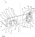
- Fig. 3 shows that in Fig. 2 Fastening module 1 shown and the elevator rail 2 during assembly.
- the elevator rail 2 is inserted between the fastening devices 15, 16. Due to the position of the second fastening device 16 rotated by 90 ° and a certain spacing, the rail foot 6 can be inserted into the position shown without dismantling the first fastening device 15.
- the first side 7 of the rail foot 6 can to a certain extent be pushed along the adjustment direction 27 or along the axis 43 into the bracket between the support area 20 and the contact area 26 of the first fastening device 15, so that the first side 7 of the elevator rail 2 on the support area 30 of the support element 17 is present.
- the second fastening device 16 initially remains loosely in the prepared position, as it is in the Fig. 2 is shown.
- Fig. 4 shows that in Fig. 3 Fastening module 1 shown and the elevator rail 2 in a schematic representation from the viewing direction labeled IV in the assembled state.
- the base plate 5 has a guide recess 50 in the form of an elongated hole 50 through which a guide 50 is formed.
- the geometry of the guide recess 50 and the interaction with the fastening means 31A result in a guide track 51.
- the second fastening device 16 can be displaced along the guide track 51 relative to the fastening plane 4.
- a rotation of the second fastening device 16 about an axis of rotation 52 is made possible, which in this embodiment corresponds to the axis 52 of the fastening means 31A.
- the axis of rotation 52 is oriented perpendicular to the fastening plane 4.
- the second fastening device 16 is first rotated about the axis of rotation 52.
- the second fastening device 16 can be rotated in a direction of rotation 53 ( Fig. 3 ) be rotated.
- the second fastening device 16 can be adjusted along the guide track 51.
- the guide track 51 has a feed section 54 and an approach section 55.
- a second inclination (angle) 57 of the approach section 55 with respect to the longitudinal axis 44 which in this exemplary embodiment is significantly smaller than 90 ° and even smaller than 45 °.
- the second fastening device comes closer to the second side 8 over a short adjustment path.
- a slower approach can be achieved via the approach section 55 with respect to the adjustment path along the guide track 51.
- a support of the second fastening device 16 on a flank 58 of the guide recess 50 can also be used here.
- assembly is facilitated by the fact that the second fastening device 16 is supported on the flank 58 via the fastening means 31A when the second fastening device 16 is acted upon by the fitter in a direction 59 parallel to the longitudinal axis 44.
- This feed movement causes the second side 8 of the rail foot 6 to pass between the contact area 26A and the support area 20A of the second fastening device 16.
- the second fastening device 16 can be rotated in the direction of rotation 53 by 90 ° at the beginning.
- the support area 30A of the support element 17A is advanced to the second side 8 of the elevator rail 2 until the support area 30A is in loose contact with the second side 8.
- the elevator rail 2 is guided laterally.
- the support element 17A can thereby be seen from the side outside the rail foot 6, as shown in FIG Fig. 3 is shown, are rotated over the top 13 of the rail foot 6.
- An attachment of the rail foot 6 between the in Fig. 1 The lateral support areas 30, 30A of the fastening devices 15, 16 shown here can be achieved in a simplified manner after the fastening means 31, 31A have been tightened.
- the fitter can adjust the contact elements 24, 24A in their respective adjustment directions 27, 27A.
- a locking can then take place via the locking means 32, 32A.
- the rail foot 6 is then fastened to the fastening plane 4 via the fastening module 1.
- This fastening enables a certain length compensation or a displacement of the elevator rail 2 along its longitudinal axis 44 with respect to the fastening module 1.
- the holding forces applied via the fastening devices 15, 16 can namely be dosed in such a way that, for example, changes in length that occur due to building settlement can be compensated for.
- the elevator rail 2 is allowed to slip through the fastening module 1.
- the guide track 51 has a bend 60.
- the guide recess 50 can also have a curved design, as a result of which such a bend 60 is omitted.
- the guide recess 50 in this exemplary embodiment has edges 61, of which only the edge 61 is identified in order to simplify the illustration. With a corresponding rounding, one or more such edges 61 can also be omitted or the edges 61 are then replaced by transition roundings.
- the guide recess 50 is composed of two rectangles 62, 63.
- the rectangles 62, 63 are here oriented parallel to the fastening plane 4 and rotated relative to one another with respect to the fastening plane 4. This twist is shown in the different inclinations 56, 57.
- Fig. 5 shows an elevator system 3 in a partial, schematic representation according to a possible embodiment of the invention.
- the elevator system 3 has several elevator rails 2, 2A, 2B, 2C.
- the elevator rails 2, 2A are part of an arrangement 70 made up of a plurality of elevator rails 2, 2A, which extend along the longitudinal axis 44 through the elevator shaft 35.
- the elevator rails 2B, 2C are part of a further such arrangement 71 comprising a plurality of elevator rails 2B, 2C.
- On the arrangement 70 for example, braking and / or guide tracks 36, 37 are produced, which extend at least substantially through the entire elevator shaft 35. Such tracks 36, 37 continue over the individual elevator rails 2, 2A.
- the elevator system 3 also has an elevator car 72 and a counterweight 73, which are connected to one another, for example, via a support and traction means 74.
- the arrangements 70, 71 and possibly other such arrangements can be used, inter alia, to guide the elevator car 72 and the counterweight 73 in the elevator shaft 35.
- Fig. 6 shows the in Fig. 5 with VI designated section of the elevator system 3 with the Arrangement 70 and fastening modules 1, 1 '.
- the fastening modules 1, 1 ' have base plates 5, 5' which are mounted in the elevator shaft 35 via a support structure or the like.
- the elevator rails 2, 2A are butted together at an interface 80.
- the elevator rails 2, 2A can be joined together at the interface 80, for example by means of connecting straps 81. This results in the uninterrupted tracks 36, 37 on the arrangement 70 from the multiple elevator rails 2, 2A.
- the rail feet 6, 6A of the elevator rails 2, 2A can differ, for example, due to manufacturing tolerances. This can result in different required holding masses 38.
- fastening modules 1, 1 'of the same construction can nevertheless be used.
- the setting of the respective holding measure 38 to the required holding measure 38, as it is based on the Fig. 1 is described is possible individually on each individual fastening module 1, 1 'during assembly.
Landscapes
- Lift-Guide Devices, And Elevator Ropes And Cables (AREA)
- Cage And Drive Apparatuses For Elevators (AREA)
Claims (14)
- Module de fixation (1) qui sert à la fixation d'un pied (6) d'un rail d'ascenseur (2) à un plan de fixation (4), comportant un premier dispositif de fixation (15) qui est fixé au plan de fixation (4) à l'état monté et qui sert à retenir un premier côté (7) du pied de rail (6), et un second dispositif de fixation (16) qui est fixé au plan de fixation (4) à l'état monté et qui sert à retenir un second côté (8) du pied de rail (6), dans lequel le second dispositif de fixation (16) est déplaçable de manière au moins sensiblement parallèle au plan de fixation (4), et dans lequel au moins un élément (17A) du second dispositif de fixation (16) qui coopère à l'état monté avec un côté supérieur (13) du pied de rail (6) opposé au plan de fixation (4) peut être tourné de manière au moins sensiblement perpendiculaire au plan de fixation (4) autour d'un axe de rotation (52) du second dispositif de fixation (16) latéralement à partir du côté extérieur du pied de rail (6) sur le côté supérieur (13) du pied de rail (6),
caractérisé en ce qu'un guide (50) est prévu, à travers lequel le second dispositif de fixation (16) est guidé le long d'un chemin de guidage (51) se trouvant dans le plan de fixation (4), et en ce que le chemin de guidage (51) présente une section d'alimentation (54) qui est orientée de sorte que le second dispositif de fixation (16) est déplaçable au moins sensiblement vers une position de montage prédéfinie du second côté (8) du pied de rail (6), et dans lequel le guidage (51) présente au moins une première et une seconde inclinaison (56, 57) par rapport à l'axe longitudinal (44) du pied de rail (6) fourni par la position de montage en projection sur le plan de fixation (4). - Module de fixation selon la revendication 1, caractérisé en ce que le guide (50) à travers lequel le second dispositif de fixation (16) est guidé le long du chemin de guidage (51) se trouvant dans le plan de fixation (4) présente une section de rapprochement (55) orientée de sorte que le second dispositif de fixation (16) est déplaçable à la fois vers une position de montage prédéfinie du second côté (8) du pied de rail (6) et parallèlement à un axe longitudinal (44) du pied de rail (6) donné par la position de montage.
- Module de fixation selon l'une des revendications 1 ou 2, caractérisé en ce que la seconde inclinaison (57) le long de la section de rapprochement (55) est toujours inférieure à 45 ° et/ou en ce que la première inclinaison (56) le long de la section d'alimentation (54) est approximativement égale à 90 °.
- Module de fixation selon l'une des revendications 1 à 3, caractérisé en ce que le chemin de guidage (51) présente un pli (60) entre la première et la seconde inclinaison (56, 57) ou entre la section d'alimentation (54) et la section de rapprochement (55).
- Module de fixation selon l'une des revendications 1 à 4, caractérisé en ce qu'une plaque de base (5) est prévue, sur laquelle le plan de fixation (4) est situé au moins indirectement, et en ce que le guide (50) est intégré dans la plaque de base (5).
- Module de fixation selon la revendication 5, caractérisé en ce que l'évidement de guidage (50) réalisé dans la plaque de base (5) présente un trou allongé (50) avec ou sans arrondis au niveau des bords (61), et/ou en ce que le trou allongé (50) est réalisé avec un pli (60) le long du chemin de guidage (51) et/ou en ce que le trou allongé (50) est composé au moins approximativement d'au moins deux formes rectangulaires (62, 63) torsadées l'une contre l'autre.
- Module de fixation selon l'une des revendications 1 à 6, caractérisé en ce que le premier dispositif de fixation (15), qui sert à retenir le premier côté (7) du pied de rail (6), est disposé de manière sensiblement fixe au plan de fixation (4).
- Module de fixation selon l'une des revendications 1 à 7, caractérisé en ce que l'élément (17A) du second dispositif de fixation (16), qui coopère avec le côté supérieur (13) du pied de rail (6) à l'état monté, est un élément d'appui (17A) et en ce qu'une zone d'appui (20A) de l'élément d'appui (17A), à l'état monté, est disposée à une distance prédéfinie (33) du plan de fixation (4).
- Module de fixation selon l'une des revendications 1 à 8, caractérisé en ce que le second dispositif de fixation (16) présente un moyen de compensation (23A) doté d'un élément de contact (24A), et en ce qu'une zone de contact (26A) est réalisée au niveau de l'élément de contact (24A), dans lequel un second côté (8) du pied de rail (6) peut être disposé entre la zone de contact (26A) de l'élément de contact (24A) et une zone d'appui (20A) d'un élément d'appui (17A) du second dispositif de fixation (16) à l'état monté.
- Module de fixation selon la revendication 9, caractérisé en ce que le moyen de compensation (23A) est conçu de telle manière qu'une masse de retenue (38) prévue entre la zone de contact (26A) et la zone d'appui (20A) peut être adaptée à une masse de retenue (38) requise pour le second côté (8) du pied de rail (6), dans lequel le second côté (8) du pied de rail (6) est retenu entre la zone de contact (26A) et la zone d'appui (20A) à l'état monté.
- Module de fixation selon la revendication 9 ou 10, caractérisé en ce que le moyen de compensation (23A) présente un élément de calage (25A), en ce que l'élément de contact (24A) et l'élément de calage (25A) sont réglables l'un par rapport à l'autre de manière au moins approximativement parallèle au plan de fixation (4), et en ce que l'élément de contact (24A) et l'élément de calage (25A) sont conçus de sorte que, entre la zone de contact (26A) et la zone d'appui (20A), une masse de retenue (38) au moins approximativement perpendiculaire au plan de fixation (4), permettant une fixation sans jeu du second côté (8) du pied de rail (6) à l'état monté, peut être modifiée par un déplacement de l'élément de contact (24A) par rapport à l'élément de calage (25A) et/ou par un déplacement de l'élément de contact (24A) par rapport au plan de fixation (4).
- Module de fixation selon l'une des revendications 1 à 11, caractérisé en ce qu'au moins l'élément (17A) du second dispositif de fixation (16) peut être tourné d'au moins environ 90 ° autour de l'axe de rotation (52) du second dispositif de fixation (16) à partir du côté extérieur du pied de rail (6) sur le côté supérieur (13) du pied de rail (6).
- Installation d'ascenseur (3) comportant au moins un agencement (70) de rails d'ascenseur (2, 2A) disposés en série le long d'un axe longitudinal (44) et plusieurs modules de fixation (1, 1') qui sont réalisés chacun selon l'une des revendications 1 à 12, dans laquelle les modules de fixation (1, 1') servent à la fixation des pieds (6, 6A) des rails d'ascenseur (2, 2A).
- Procédé de fixation d'un pied (6) d'un rail d'ascenseur (2), qui est réalisé avec au moins un module de fixation (1) selon l'une des revendications 1 à 12, dans lequel le module de fixation (1) est monté, dans lequel le premier côté (7) du pied de rail (6) est inséré entre une zone de contact (26) et une zone d'appui (20) du premier dispositif de fixation (15), et dans lequel le second dispositif de fixation (16) est tourné et déplacé de sorte que le second côté (8) du pied de rail (6) est disposé entre une zone de contact (26A) et une zone d'appui (20A) du second dispositif de fixation (16).
Priority Applications (1)
| Application Number | Priority Date | Filing Date | Title |
|---|---|---|---|
| PL16809850T PL3390260T3 (pl) | 2015-12-17 | 2016-12-15 | Moduł mocujący do mocowania szyn windy |
Applications Claiming Priority (2)
| Application Number | Priority Date | Filing Date | Title |
|---|---|---|---|
| EP15200954 | 2015-12-17 | ||
| PCT/EP2016/081306 WO2017103017A1 (fr) | 2015-12-17 | 2016-12-15 | Module de fixation servant à la fixation de rails d'ascenseur |
Publications (2)
| Publication Number | Publication Date |
|---|---|
| EP3390260A1 EP3390260A1 (fr) | 2018-10-24 |
| EP3390260B1 true EP3390260B1 (fr) | 2020-08-19 |
Family
ID=54979456
Family Applications (1)
| Application Number | Title | Priority Date | Filing Date |
|---|---|---|---|
| EP16809850.7A Active EP3390260B1 (fr) | 2015-12-17 | 2016-12-15 | Module de fixation de rails d'ascenseur |
Country Status (12)
| Country | Link |
|---|---|
| US (1) | US11180345B2 (fr) |
| EP (1) | EP3390260B1 (fr) |
| KR (1) | KR102636759B1 (fr) |
| CN (1) | CN108698794B (fr) |
| AU (1) | AU2016372444B2 (fr) |
| BR (1) | BR112018012224B1 (fr) |
| CA (1) | CA3007748A1 (fr) |
| HK (1) | HK1259140A1 (fr) |
| MX (1) | MX2018007183A (fr) |
| MY (1) | MY192437A (fr) |
| PL (1) | PL3390260T3 (fr) |
| WO (1) | WO2017103017A1 (fr) |
Families Citing this family (10)
| Publication number | Priority date | Publication date | Assignee | Title |
|---|---|---|---|---|
| EP3118151B1 (fr) * | 2015-07-17 | 2019-06-12 | KONE Corporation | Support de rail de guidage d'ascenseur et procédé de fixation d'un rail de guidage |
| KR102213646B1 (ko) * | 2015-09-11 | 2021-02-08 | 미쓰비시덴키 가부시키가이샤 | 가이드 레일 고정 장치 |
| WO2017108495A1 (fr) * | 2015-12-22 | 2017-06-29 | Inventio Ag | Pince de fixation de rail de guidage d'ascenseur |
| WO2018104435A1 (fr) * | 2016-12-07 | 2018-06-14 | Inventio Ag | Support de patin de rail pour fixer un rail d'une installation d'ascenseur |
| US20230135086A1 (en) * | 2016-12-07 | 2023-05-04 | Inventio Ag | Rail foot holder for fastening a rail of an elevator system |
| ES2727504B2 (es) * | 2018-04-16 | 2020-10-16 | S A De Vera Savera | Brida ajustable al espesor del ala de una guía de ascensor |
| EP3947232A2 (fr) * | 2019-03-26 | 2022-02-09 | Inventio AG | Dispositif d'alignement et procédé d'alignement d'un rail de guidage d'une installation d'ascenseur |
| WO2021110546A1 (fr) * | 2019-12-05 | 2021-06-10 | Inventio Ag | Fixation d'un composant de levage sur une paroi d'arbre |
| EP3858777B1 (fr) * | 2020-02-03 | 2023-08-23 | KONE Corporation | Agencement de fixation pour rails de guidage d'ascenseur |
| CN114084773A (zh) | 2020-08-24 | 2022-02-25 | 奥的斯电梯公司 | 模块化电梯组件和导轨 |
Family Cites Families (27)
| Publication number | Priority date | Publication date | Assignee | Title |
|---|---|---|---|---|
| US620912A (en) * | 1899-03-14 | Rail-fastener | ||
| US1505345A (en) | 1924-03-20 | 1924-08-19 | Leopold F Heptner | Rail clamp |
| US1925867A (en) | 1931-11-21 | 1933-09-05 | Westinghouse Elec Elevator Co | Elevator guide-rail supporting device |
| US2451414A (en) * | 1946-11-08 | 1948-10-12 | Snyder Jacob Rush | Rail holding device |
| DE1139254B (de) | 1956-01-24 | 1962-11-08 | Otis Elevator Co | Befestigungsvorrichtung fuer Fuehrungsschienen von Aufzuegen |
| US2848077A (en) * | 1956-01-24 | 1958-08-19 | Otis Elevator Co | Elevator guide rail fastener |
| CH484826A (de) | 1969-06-04 | 1970-01-31 | Inventio Ag | Befestigungsvorrichtung für Führungsschienen von Aufzügen |
| US3982692A (en) | 1974-07-19 | 1976-09-28 | R. Stahl Aufzuege Gmbh | Clamping means for elevator guide rails and the like |
| US4431087A (en) * | 1981-05-29 | 1984-02-14 | Westinghouse Electric Corp. | Guide rail clamping method and assembly |
| US4572431A (en) * | 1981-06-22 | 1986-02-25 | Penta Construction Corp. | Rail fastener assembly |
| US4577729A (en) * | 1984-12-05 | 1986-03-25 | Westinghouse Electric Corp. | Guide rail clamping assembly |
| GB8620832D0 (en) * | 1986-08-28 | 1986-10-08 | Cranequip Ltd | Rail clip assembly |
| US4844338A (en) * | 1986-12-05 | 1989-07-04 | Lord Corporation | Rail fastener |
| CH680786A5 (fr) | 1990-03-26 | 1992-11-13 | Inventio Ag | |
| US6371249B1 (en) * | 2000-06-02 | 2002-04-16 | Otis Elevator Company | Quick connector apparatus for elevator guide rail section |
| US6830133B2 (en) | 2002-03-06 | 2004-12-14 | Terryle L. Sneed | Connector brackets |
| KR100960439B1 (ko) | 2006-03-22 | 2010-05-28 | 미쓰비시덴키 가부시키가이샤 | 엘리베이터용 가이드 레일의 지지장치 |
| ES2341071B1 (es) * | 2008-10-09 | 2011-06-06 | Orona S. Coop | Dispositivo para unir guias de aparatos elevadores, aparato elevador que comprende dicho dispositivo y metodo para montar guias de aparatoselevadores. |
| FI20090502A (fi) * | 2009-12-22 | 2011-06-23 | Kone Corp | Hissi, johdekiinnike ja menetelmä |
| US20120133164A1 (en) * | 2010-11-29 | 2012-05-31 | S.A. De Vera (Savera) | Adjustment flange for lift guides |
| ES2421083B1 (es) | 2012-02-22 | 2014-11-04 | S.A. De Vera (Savera) | Sistema de brida adaptable, para guías de ascensor |
| FR2996216B1 (fr) | 2012-10-03 | 2015-04-17 | Sodimas | Fixation d'un guide d'ascenseur a une paroi |
| ES2492791B1 (es) | 2013-03-08 | 2015-05-28 | S.A. De Vera (Savera) | Brida para guías de ascensor |
| JP6182404B2 (ja) | 2013-09-11 | 2017-08-16 | 株式会社日立製作所 | エレベータ装置 |
| ES2557505B1 (es) | 2014-07-24 | 2016-11-03 | S.A. De Vera (Savera) | Brida adaptable para guías de ascensor |
| WO2017103016A1 (fr) * | 2015-12-17 | 2017-06-22 | Inventio Ag | Dispositifs de fixation servant à la fixation de rails d'ascenseur |
| EP3231757B1 (fr) * | 2016-04-15 | 2020-04-08 | Otis Elevator Company | Support de rail de guidage |
-
2016
- 2016-12-15 PL PL16809850T patent/PL3390260T3/pl unknown
- 2016-12-15 CN CN201680082017.3A patent/CN108698794B/zh active Active
- 2016-12-15 BR BR112018012224-6A patent/BR112018012224B1/pt active IP Right Grant
- 2016-12-15 AU AU2016372444A patent/AU2016372444B2/en active Active
- 2016-12-15 MY MYPI2018702217A patent/MY192437A/en unknown
- 2016-12-15 EP EP16809850.7A patent/EP3390260B1/fr active Active
- 2016-12-15 WO PCT/EP2016/081306 patent/WO2017103017A1/fr active Application Filing
- 2016-12-15 US US16/063,403 patent/US11180345B2/en active Active
- 2016-12-15 MX MX2018007183A patent/MX2018007183A/es unknown
- 2016-12-15 KR KR1020187020336A patent/KR102636759B1/ko active IP Right Grant
- 2016-12-15 CA CA3007748A patent/CA3007748A1/fr active Pending
-
2019
- 2019-01-22 HK HK19101105.9A patent/HK1259140A1/zh unknown
Non-Patent Citations (1)
| Title |
|---|
| None * |
Also Published As
| Publication number | Publication date |
|---|---|
| MX2018007183A (es) | 2018-08-01 |
| AU2016372444B2 (en) | 2019-09-19 |
| EP3390260A1 (fr) | 2018-10-24 |
| WO2017103017A1 (fr) | 2017-06-22 |
| CA3007748A1 (fr) | 2017-06-22 |
| BR112018012224B1 (pt) | 2022-07-19 |
| KR20180096689A (ko) | 2018-08-29 |
| KR102636759B1 (ko) | 2024-02-14 |
| US20180370766A1 (en) | 2018-12-27 |
| PL3390260T3 (pl) | 2021-02-08 |
| BR112018012224A2 (pt) | 2018-11-27 |
| CN108698794B (zh) | 2020-02-21 |
| US11180345B2 (en) | 2021-11-23 |
| CN108698794A (zh) | 2018-10-23 |
| MY192437A (en) | 2022-08-19 |
| HK1259140A1 (zh) | 2019-11-29 |
| AU2016372444A1 (en) | 2018-07-05 |
Similar Documents
| Publication | Publication Date | Title |
|---|---|---|
| EP3390260B1 (fr) | Module de fixation de rails d'ascenseur | |
| EP3390261B1 (fr) | Dispositifs de fixation de rails d'ascenseur | |
| EP2229479B1 (fr) | Appui pour un système de fixation d'un rail et système de fixation d'un rail | |
| EP2662645A2 (fr) | Support de module solaire | |
| EP1647782A2 (fr) | Dispositif de support d'au moins un collecteur solaire | |
| EP3460267A1 (fr) | Système de fixation de plaques de main-courante | |
| EP3586018B1 (fr) | Dispositif de fixation et module de fixation | |
| DE102006029396A1 (de) | Befestigungssystem für Solarmodule | |
| EP2060699B1 (fr) | Dispositif de fixation d'éléments de revêtement ou structure de support pour éléments de revêtement | |
| DE3333954A1 (de) | Verstellbare haltevorrichtung fuer verkleidungsplatten | |
| WO2012163940A1 (fr) | Accouplement variable entre une porte de cabine et une porte de cage d'ascenseur | |
| EP3472403A1 (fr) | Dispositif servant à fixer un élément en forme de plaque dans une rainure de réception d'un rail de support | |
| DE202011108873U1 (de) | Vorrichtung zum Befestigen eines Moduls zur Nutzung von Sonnenenergie | |
| WO2014001373A1 (fr) | Dispositif et procédé destinés à fixer et orienter un rail de guidage | |
| EP3722527B1 (fr) | Dispositif de fixation permettant de fixer des éléments de façade d'une façade à éléments | |
| EP3381856A1 (fr) | Ensemble de fixation comprenant un élément de fixation pour fixer un rail d'un ascenseur dans une cage d'ascenseur | |
| DE3823000C2 (de) | Befestigungselement | |
| EP1388674B1 (fr) | Dispositif de fixation d'un sabot de ligne de conduite | |
| EP2682681B1 (fr) | Dispositif de fixation pour fixer un corps de refroidissement ou de chauffage | |
| EP1870534A2 (fr) | Structure de raidissement, élément de fixation et procédé destiné au raidissement du cadre de support d'un coffrage de plafond | |
| DE102008027603B4 (de) | Solarmodulbefestigungsvorrichtung | |
| EP3623721B1 (fr) | Crochet de toit | |
| EP1857604B1 (fr) | Plafond suspendu pour laboratoires et son procédé de montage | |
| EP2295696A1 (fr) | Portail multi-sections | |
| EP3623722A1 (fr) | Crochet de toit |
Legal Events
| Date | Code | Title | Description |
|---|---|---|---|
| STAA | Information on the status of an ep patent application or granted ep patent |
Free format text: STATUS: UNKNOWN |
|
| STAA | Information on the status of an ep patent application or granted ep patent |
Free format text: STATUS: THE INTERNATIONAL PUBLICATION HAS BEEN MADE |
|
| PUAI | Public reference made under article 153(3) epc to a published international application that has entered the european phase |
Free format text: ORIGINAL CODE: 0009012 |
|
| STAA | Information on the status of an ep patent application or granted ep patent |
Free format text: STATUS: REQUEST FOR EXAMINATION WAS MADE |
|
| 17P | Request for examination filed |
Effective date: 20180605 |
|
| AK | Designated contracting states |
Kind code of ref document: A1 Designated state(s): AL AT BE BG CH CY CZ DE DK EE ES FI FR GB GR HR HU IE IS IT LI LT LU LV MC MK MT NL NO PL PT RO RS SE SI SK SM TR |
|
| AX | Request for extension of the european patent |
Extension state: BA ME |
|
| DAV | Request for validation of the european patent (deleted) | ||
| DAX | Request for extension of the european patent (deleted) | ||
| TPAC | Observations filed by third parties |
Free format text: ORIGINAL CODE: EPIDOSNTIPA |
|
| GRAP | Despatch of communication of intention to grant a patent |
Free format text: ORIGINAL CODE: EPIDOSNIGR1 |
|
| STAA | Information on the status of an ep patent application or granted ep patent |
Free format text: STATUS: GRANT OF PATENT IS INTENDED |
|
| INTG | Intention to grant announced |
Effective date: 20200319 |
|
| GRAS | Grant fee paid |
Free format text: ORIGINAL CODE: EPIDOSNIGR3 |
|
| GRAA | (expected) grant |
Free format text: ORIGINAL CODE: 0009210 |
|
| STAA | Information on the status of an ep patent application or granted ep patent |
Free format text: STATUS: THE PATENT HAS BEEN GRANTED |
|
| AK | Designated contracting states |
Kind code of ref document: B1 Designated state(s): AL AT BE BG CH CY CZ DE DK EE ES FI FR GB GR HR HU IE IS IT LI LT LU LV MC MK MT NL NO PL PT RO RS SE SI SK SM TR |
|
| REG | Reference to a national code |
Ref country code: CH Ref legal event code: EP |
|
| REG | Reference to a national code |
Ref country code: DE Ref legal event code: R096 Ref document number: 502016010914 Country of ref document: DE |
|
| REG | Reference to a national code |
Ref country code: AT Ref legal event code: REF Ref document number: 1303718 Country of ref document: AT Kind code of ref document: T Effective date: 20200915 |
|
| REG | Reference to a national code |
Ref country code: IE Ref legal event code: FG4D Free format text: LANGUAGE OF EP DOCUMENT: GERMAN |
|
| REG | Reference to a national code |
Ref country code: NL Ref legal event code: FP |
|
| REG | Reference to a national code |
Ref country code: LT Ref legal event code: MG4D |
|
| PG25 | Lapsed in a contracting state [announced via postgrant information from national office to epo] |
Ref country code: PT Free format text: LAPSE BECAUSE OF FAILURE TO SUBMIT A TRANSLATION OF THE DESCRIPTION OR TO PAY THE FEE WITHIN THE PRESCRIBED TIME-LIMIT Effective date: 20201221 Ref country code: LT Free format text: LAPSE BECAUSE OF FAILURE TO SUBMIT A TRANSLATION OF THE DESCRIPTION OR TO PAY THE FEE WITHIN THE PRESCRIBED TIME-LIMIT Effective date: 20200819 Ref country code: BG Free format text: LAPSE BECAUSE OF FAILURE TO SUBMIT A TRANSLATION OF THE DESCRIPTION OR TO PAY THE FEE WITHIN THE PRESCRIBED TIME-LIMIT Effective date: 20201119 Ref country code: NO Free format text: LAPSE BECAUSE OF FAILURE TO SUBMIT A TRANSLATION OF THE DESCRIPTION OR TO PAY THE FEE WITHIN THE PRESCRIBED TIME-LIMIT Effective date: 20201119 Ref country code: SE Free format text: LAPSE BECAUSE OF FAILURE TO SUBMIT A TRANSLATION OF THE DESCRIPTION OR TO PAY THE FEE WITHIN THE PRESCRIBED TIME-LIMIT Effective date: 20200819 Ref country code: HR Free format text: LAPSE BECAUSE OF FAILURE TO SUBMIT A TRANSLATION OF THE DESCRIPTION OR TO PAY THE FEE WITHIN THE PRESCRIBED TIME-LIMIT Effective date: 20200819 Ref country code: GR Free format text: LAPSE BECAUSE OF FAILURE TO SUBMIT A TRANSLATION OF THE DESCRIPTION OR TO PAY THE FEE WITHIN THE PRESCRIBED TIME-LIMIT Effective date: 20201120 Ref country code: FI Free format text: LAPSE BECAUSE OF FAILURE TO SUBMIT A TRANSLATION OF THE DESCRIPTION OR TO PAY THE FEE WITHIN THE PRESCRIBED TIME-LIMIT Effective date: 20200819 |
|
| PG25 | Lapsed in a contracting state [announced via postgrant information from national office to epo] |
Ref country code: IS Free format text: LAPSE BECAUSE OF FAILURE TO SUBMIT A TRANSLATION OF THE DESCRIPTION OR TO PAY THE FEE WITHIN THE PRESCRIBED TIME-LIMIT Effective date: 20201219 Ref country code: LV Free format text: LAPSE BECAUSE OF FAILURE TO SUBMIT A TRANSLATION OF THE DESCRIPTION OR TO PAY THE FEE WITHIN THE PRESCRIBED TIME-LIMIT Effective date: 20200819 Ref country code: RS Free format text: LAPSE BECAUSE OF FAILURE TO SUBMIT A TRANSLATION OF THE DESCRIPTION OR TO PAY THE FEE WITHIN THE PRESCRIBED TIME-LIMIT Effective date: 20200819 |
|
| PGFP | Annual fee paid to national office [announced via postgrant information from national office to epo] |
Ref country code: NL Payment date: 20201229 Year of fee payment: 5 |
|
| PG25 | Lapsed in a contracting state [announced via postgrant information from national office to epo] |
Ref country code: RO Free format text: LAPSE BECAUSE OF FAILURE TO SUBMIT A TRANSLATION OF THE DESCRIPTION OR TO PAY THE FEE WITHIN THE PRESCRIBED TIME-LIMIT Effective date: 20200819 Ref country code: DK Free format text: LAPSE BECAUSE OF FAILURE TO SUBMIT A TRANSLATION OF THE DESCRIPTION OR TO PAY THE FEE WITHIN THE PRESCRIBED TIME-LIMIT Effective date: 20200819 Ref country code: CZ Free format text: LAPSE BECAUSE OF FAILURE TO SUBMIT A TRANSLATION OF THE DESCRIPTION OR TO PAY THE FEE WITHIN THE PRESCRIBED TIME-LIMIT Effective date: 20200819 Ref country code: SM Free format text: LAPSE BECAUSE OF FAILURE TO SUBMIT A TRANSLATION OF THE DESCRIPTION OR TO PAY THE FEE WITHIN THE PRESCRIBED TIME-LIMIT Effective date: 20200819 Ref country code: EE Free format text: LAPSE BECAUSE OF FAILURE TO SUBMIT A TRANSLATION OF THE DESCRIPTION OR TO PAY THE FEE WITHIN THE PRESCRIBED TIME-LIMIT Effective date: 20200819 |
|
| REG | Reference to a national code |
Ref country code: DE Ref legal event code: R097 Ref document number: 502016010914 Country of ref document: DE |
|
| PG25 | Lapsed in a contracting state [announced via postgrant information from national office to epo] |
Ref country code: ES Free format text: LAPSE BECAUSE OF FAILURE TO SUBMIT A TRANSLATION OF THE DESCRIPTION OR TO PAY THE FEE WITHIN THE PRESCRIBED TIME-LIMIT Effective date: 20200819 Ref country code: AL Free format text: LAPSE BECAUSE OF FAILURE TO SUBMIT A TRANSLATION OF THE DESCRIPTION OR TO PAY THE FEE WITHIN THE PRESCRIBED TIME-LIMIT Effective date: 20200819 |
|
| PLBE | No opposition filed within time limit |
Free format text: ORIGINAL CODE: 0009261 |
|
| STAA | Information on the status of an ep patent application or granted ep patent |
Free format text: STATUS: NO OPPOSITION FILED WITHIN TIME LIMIT |
|
| PG25 | Lapsed in a contracting state [announced via postgrant information from national office to epo] |
Ref country code: SK Free format text: LAPSE BECAUSE OF FAILURE TO SUBMIT A TRANSLATION OF THE DESCRIPTION OR TO PAY THE FEE WITHIN THE PRESCRIBED TIME-LIMIT Effective date: 20200819 |
|
| 26N | No opposition filed |
Effective date: 20210520 |
|
| PG25 | Lapsed in a contracting state [announced via postgrant information from national office to epo] |
Ref country code: IT Free format text: LAPSE BECAUSE OF FAILURE TO SUBMIT A TRANSLATION OF THE DESCRIPTION OR TO PAY THE FEE WITHIN THE PRESCRIBED TIME-LIMIT Effective date: 20200819 |
|
| REG | Reference to a national code |
Ref country code: CH Ref legal event code: PL |
|
| PG25 | Lapsed in a contracting state [announced via postgrant information from national office to epo] |
Ref country code: MC Free format text: LAPSE BECAUSE OF FAILURE TO SUBMIT A TRANSLATION OF THE DESCRIPTION OR TO PAY THE FEE WITHIN THE PRESCRIBED TIME-LIMIT Effective date: 20200819 Ref country code: SI Free format text: LAPSE BECAUSE OF FAILURE TO SUBMIT A TRANSLATION OF THE DESCRIPTION OR TO PAY THE FEE WITHIN THE PRESCRIBED TIME-LIMIT Effective date: 20200819 |
|
| REG | Reference to a national code |
Ref country code: BE Ref legal event code: MM Effective date: 20201231 |
|
| PG25 | Lapsed in a contracting state [announced via postgrant information from national office to epo] |
Ref country code: IE Free format text: LAPSE BECAUSE OF NON-PAYMENT OF DUE FEES Effective date: 20201215 Ref country code: LU Free format text: LAPSE BECAUSE OF NON-PAYMENT OF DUE FEES Effective date: 20201215 |
|
| PG25 | Lapsed in a contracting state [announced via postgrant information from national office to epo] |
Ref country code: CH Free format text: LAPSE BECAUSE OF NON-PAYMENT OF DUE FEES Effective date: 20201231 Ref country code: LI Free format text: LAPSE BECAUSE OF NON-PAYMENT OF DUE FEES Effective date: 20201231 |
|
| PG25 | Lapsed in a contracting state [announced via postgrant information from national office to epo] |
Ref country code: TR Free format text: LAPSE BECAUSE OF FAILURE TO SUBMIT A TRANSLATION OF THE DESCRIPTION OR TO PAY THE FEE WITHIN THE PRESCRIBED TIME-LIMIT Effective date: 20200819 Ref country code: MT Free format text: LAPSE BECAUSE OF FAILURE TO SUBMIT A TRANSLATION OF THE DESCRIPTION OR TO PAY THE FEE WITHIN THE PRESCRIBED TIME-LIMIT Effective date: 20200819 Ref country code: CY Free format text: LAPSE BECAUSE OF FAILURE TO SUBMIT A TRANSLATION OF THE DESCRIPTION OR TO PAY THE FEE WITHIN THE PRESCRIBED TIME-LIMIT Effective date: 20200819 |
|
| PG25 | Lapsed in a contracting state [announced via postgrant information from national office to epo] |
Ref country code: MK Free format text: LAPSE BECAUSE OF FAILURE TO SUBMIT A TRANSLATION OF THE DESCRIPTION OR TO PAY THE FEE WITHIN THE PRESCRIBED TIME-LIMIT Effective date: 20200819 |
|
| PG25 | Lapsed in a contracting state [announced via postgrant information from national office to epo] |
Ref country code: BE Free format text: LAPSE BECAUSE OF NON-PAYMENT OF DUE FEES Effective date: 20201231 |
|
| REG | Reference to a national code |
Ref country code: NL Ref legal event code: MM Effective date: 20220101 |
|
| PG25 | Lapsed in a contracting state [announced via postgrant information from national office to epo] |
Ref country code: NL Free format text: LAPSE BECAUSE OF NON-PAYMENT OF DUE FEES Effective date: 20220101 |
|
| REG | Reference to a national code |
Ref country code: AT Ref legal event code: MM01 Ref document number: 1303718 Country of ref document: AT Kind code of ref document: T Effective date: 20211215 |
|
| PGFP | Annual fee paid to national office [announced via postgrant information from national office to epo] |
Ref country code: PL Payment date: 20221206 Year of fee payment: 7 |
|
| PG25 | Lapsed in a contracting state [announced via postgrant information from national office to epo] |
Ref country code: AT Free format text: LAPSE BECAUSE OF NON-PAYMENT OF DUE FEES Effective date: 20211215 |
|
| PGFP | Annual fee paid to national office [announced via postgrant information from national office to epo] |
Ref country code: GB Payment date: 20231219 Year of fee payment: 8 |
|
| PGFP | Annual fee paid to national office [announced via postgrant information from national office to epo] |
Ref country code: FR Payment date: 20231226 Year of fee payment: 8 |
|
| PGFP | Annual fee paid to national office [announced via postgrant information from national office to epo] |
Ref country code: DE Payment date: 20231227 Year of fee payment: 8 |