EP3390261B1 - Dispositifs de fixation de rails d'ascenseur - Google Patents
Dispositifs de fixation de rails d'ascenseur Download PDFInfo
- Publication number
- EP3390261B1 EP3390261B1 EP16812948.4A EP16812948A EP3390261B1 EP 3390261 B1 EP3390261 B1 EP 3390261B1 EP 16812948 A EP16812948 A EP 16812948A EP 3390261 B1 EP3390261 B1 EP 3390261B1
- Authority
- EP
- European Patent Office
- Prior art keywords
- rail
- rail foot
- fastening
- elevator
- fastening device
- Prior art date
- Legal status (The legal status is an assumption and is not a legal conclusion. Google has not performed a legal analysis and makes no representation as to the accuracy of the status listed.)
- Active
Links
Images


Classifications
-
- B—PERFORMING OPERATIONS; TRANSPORTING
- B66—HOISTING; LIFTING; HAULING
- B66B—ELEVATORS; ESCALATORS OR MOVING WALKWAYS
- B66B7/00—Other common features of elevators
- B66B7/02—Guideways; Guides
- B66B7/023—Mounting means therefor
- B66B7/024—Lateral supports
-
- B—PERFORMING OPERATIONS; TRANSPORTING
- B66—HOISTING; LIFTING; HAULING
- B66B—ELEVATORS; ESCALATORS OR MOVING WALKWAYS
- B66B19/00—Mining-hoist operation
- B66B19/002—Mining-hoist operation installing or exchanging guide rails
-
- B—PERFORMING OPERATIONS; TRANSPORTING
- B66—HOISTING; LIFTING; HAULING
- B66B—ELEVATORS; ESCALATORS OR MOVING WALKWAYS
- B66B7/00—Other common features of elevators
- B66B7/02—Guideways; Guides
- B66B7/021—Guideways; Guides with a particular position in the shaft
Definitions
- the invention relates to a fastening device which is used to fasten one side of a rail foot of an elevator rail relative to a fastening plane, and to an elevator installation with one or more elevator rails which are mounted in an elevator shaft or the like with such fastening devices. Furthermore, the invention relates to a method for fastening a rail foot of an elevator rail, which is carried out with such fastening devices. In particular, the invention relates to the field of elevator systems that are installed in tall buildings and extend over a large number of floors.
- the DE-AS 1 139 254 relates to a guide rail fastening device for attaching guide rails of elevators to a supporting structure. This is based on the knowledge that it is advantageous if relative upward movements of the guide rail sections are made possible in the case of building construction.
- fastening holes in a support plate for pushing through bolts for guide rail clips are designed as elongated holes, which with their longitudinal axes point upward away from the adjacent web wall of the guide rail profile, with guide rail clips resiliently resting against flanges of the guide rail .
- a fastening device for guide rails of elevators is known.
- This fastening device is based on the knowledge that when fastening guide rails for elevators it must be taken into account that the length of the guide rails changes when the temperature changes and that the shaft masonry may contract over time. Therefore a longitudinal displacement between the guide rails and the shaft masonry should be permitted.
- the proposed fastening device holds the guide rail firmly in the horizontal direction, but does not clamp it firmly in the vertical direction.
- a rail clamp is arranged on both sides of the guide rail.
- a rail clamp consists of two circular disks of different diameters lying on top of each other on a coaxial axis, which merge into one another conically. To set a game, several spacers are inserted between the support plate and the rail bracket.
- a fastening device for the guide rails of elevators is known.
- a change in a pretensioning force of the rail clamp can be achieved in that a semicircular profile serving as a lining for the guide rail has different thicknesses. To do this, it is necessary to determine which semicircular profile is required and must be delivered before the elevator system is installed.
- US 2003/0168291 discloses a fastening device according to the preamble of claim 1.
- the elevator rails can be attached directly or indirectly to a building wall.
- the elevator rails which serve, for example, as guide rails for the elevator car or the counterweight, can extend over the entire travel distance of the elevator, which in many cases corresponds approximately to the height of the building.
- the elevator rails are to be fastened so strongly in the building that they can safely accommodate lateral managers.
- the height of the building can change over time.
- the building shrinks, for example, as a result of the building drying out and settling.
- the temperature of the building and sunshine can also cause changes in the height of the building.
- the elevator rails can thus shift relative to the building, and in particular the building height can be shortened relative to the elevator rails.
- fastening points of the elevator rails are to be designed in such a way that length compensation is possible, but at the same time there is sufficient fastening to accommodate executives.
- An object of the invention is to provide a fastening device for an elevator rail, an elevator installation with a plurality of fastening devices and a method for fastening an elevator rail, which are of improved design. Specifically, it is an object of the invention to provide a fastening device for an elevator rail, an elevator installation with a plurality of such fastening devices and a method for fastening an elevator rail, which enable improved fastening, in which both a relative displacement of the elevator rail along its extension enables and a Movement or twist in a perpendicular to the plane of the extension is prevented.
- the fastening device which is used to fasten one side of a rail foot of an elevator rail relative to a fastening plane, can be designed with a support area and a contact area between which the side of the rail foot can be arranged, with a compensating means being provided, which is a first element and has a second element which can be displaced relative to one another along an adjustment direction which serves to fasten the side of the rail foot of the elevator rail.
- the first element and the second element are designed in such a way that between the contact area and the support area, a holding dimension viewed perpendicular to the adjustment direction, in which play-free attachment of one side of a rail foot between the contact area and the support area is made possible by one in the adjustment direction displacement of the first element that takes place can be changed relative to the second element.
- the contact area faces an underside of the rail foot and the support area faces an upper side of the rail foot.
- the support region is preferably formed on the first element.
- the support area is formed on at least one projection formed on the first element.
- the elevator rail is not part of the fastening device.
- the fastening device can also be manufactured and sold independently of an elevator rail or other components of an elevator installation.
- several such fastening devices can be used to connect the elevator rails, for example in an elevator shaft, to a supporting structure connected to a shaft wall.
- the mounting level is then stationary with respect to the shaft wall or the supporting structure.
- fastening devices they do not necessarily have the same fastening level.
- other fastening options for the elevator rails may also be used when fastening the elevator rails, if this is expedient. This enables a combination of conventional fastening options with the proposed fastening devices.
- the mounting level is usually aligned when it is installed in the elevator installation in such a way that the elevator rails held on the mounting level follow a vertical alignment.
- a pair of opposing fasteners together form a pair of fasteners. Together they hold the elevator rail in place.
- the pair of opposing fastening devices is usually arranged on one and the same fastening plane.
- the two opposing fastening devices can be of the same type, but they can also be of different types.
- the fastening device enables adaptation to the respective elevator rail that is being assembled.
- an adaptation to a thickness of the rail foot and / or a surface of the rail foot of a specific elevator rail, which is fastened with the respective fastening device is possible.
- a specific holding dimension is then correspondingly obtained, the fastening device allowing adjustment to this specific holding dimension.
- the fastening device is thus used for fastening a specific side of a rail foot of a specific elevator rail relative to a fastening level, then the fastening device is advantageously designed with a support area and a contact area between which the side of the rail foot can be arranged.
- a compensating means is provided, the compensating means having a first element and a second element, which run along an adjustment direction used to fasten the side of the rail foot of the elevator rail are displaceable relative to each other.
- the first element and the second element are designed in such a way that between the contact area and the support area the holding dimension considered perpendicular to the adjustment direction, in which a play-free fastening of the specific side of the rail foot of the specific elevator rail is made possible between the contact area and the support area displacement of the first element relative to the second element can be adjusted in the adjustment direction.
- At least one first sliding surface is formed on the first element, which has a constant or variable inclination with respect to the adjustment direction.
- at least one second sliding surface is formed on the second element, which has a constant or variable inclination with respect to the adjustment direction. It is also advantageous here that the sliding surfaces formed on the elements face one another. The inclination of the second sliding surface advantageously corresponds to the inclination of the first sliding surface.
- the first sliding surface and the second sliding surface work together to set the holding dimension.
- the holding dimension can thus be set exactly according to a local dimension of the rail foot.
- the first and second elements can be made essentially rigid, that is, inelastic. Since the rail foot is kept free of play, it can be moved lengthways and at the same time it is prevented from tipping or shifting to the side.
- such a sliding surface is formed on a wedge-shaped part of the corresponding element.
- the sliding surface it is possible for the sliding surface to be formed on a curved part of this element.
- the one element can also be designed in one way and the other element in the other way.
- Another possible solution consists in an elevator installation with at least one arrangement of elevator rails arranged one behind the other along a longitudinal axis and a plurality of fastening devices, each of which is designed in a proposed manner, the fastening devices being assigned to the sides of the rail feet of the elevator rails and each of these fastening devices making an adjustment of the holding dimension required on the assigned side of the rail foot of the assigned elevator rail.
- the elevator rails arranged one behind the other in their longitudinal direction which can also be referred to as elevator rail sections, then in the assembled state form an arrangement on the braking and / or guideways which extends essentially over the entire height of the elevator shaft. In its entirety, such an arrangement can also be referred to as an elevator car guide rail or counterweight guide rail.
- each individual elevator rail can be mounted on each of its sides using a certain number of fastening devices.
- the particular advantage here is that no preparatory measures are required to adapt to, for example, production-related differences between the elevator rails.
- the adjustment of the required holding dimension can take place by the displacement of the first element relative to the second element in the direction of adjustment directly when the respective elevator rail is installed at its installation location.
- a proposed solution also consists in a method for fastening a rail foot of an elevator rail, which is carried out with at least one fastening device which is designed in a proposed manner, the fastening device being mounted with respect to a fastening plane and wherein the displacement of the first element is fastened relative to the second element of the rail foot with respect to the fastening plane.
- a first fastening device on a first side of the rail foot and a second fastening device on a second side of the rail foot are mounted opposite to the rail foot so that the first fastening device and the second fastening device fix the rail foot along the adjustment direction, but allow the rail foot to be displaced along a longitudinal axis of the elevator rail.
- the plurality of fastening devices can be mounted in pairs on a first side of the rail foot and on a second side of the rail foot opposite one another.
- other assemblies are also possible in the respective application.
- the proposed fastening devices are provided only on one side of the rail foot, while another type of fastening can be implemented on the other side, for example.
- Another type of fastening can consist, for example, of a rigid fastening clip which is suitably screwed on and has no mutually adjustable elements.
- first element and the second element are designed in such a way that the holding dimension, in which play-free fastening of one side of a rail foot between the contact region and the support region is made possible by the displacement of the first element in the adjustment direction relative to the second element can be continuously reduced until the side of the rail foot of the elevator rail is fastened without play between the contact area and the support area.
- it is thus possible to adapt the holding dimension to any side of a rail foot of any elevator rail.
- the setting of the holding dimension takes place in that the holding dimension can be continuously reduced by the displacement of the first element relative to the second element in the direction of adjustment until the selected side of the rail foot of the specific elevator rail between the contact area and the support area is attached without play.
- this makes it possible to adapt to variations in the thickness of the rail foot that are caused by production technology.
- torsion of the elevator rail around its longitudinal direction is in particular reliably prevented. Movements of the elevator rail in a plane that is perpendicular to the longitudinal direction of the elevator rail can also be effectively restricted.
- fastened without play means that the rail foot is defined in its transverse position and, however, the rail foot can move along a longitudinal axis of the elevator rail in the event of a relative change in length between the building and the elevator rail.
- the attachment takes place here using such a first fastening device on a first side of the rail foot and using a second fastening device on a second side of the rail foot, so that they are mounted opposite one another on the rail foot.
- the second fastening device can preferably be of the same type, but it can also be constructed differently.
- the respective second elements of the fastening devices lying opposite one another preferably each have a stop.
- the rail base is positioned overall in the direction of adjustment. The positioning takes place in such a way that the rail foot is also kept free of play in the adjustment direction.
- the second element for fastening the side of the rail foot with respect to the adjustment direction is held at least substantially stationary with respect to the fastening plane when the first element for fastening the side of the rail foot is displaced relative to the second element in the adjustment direction.
- the contact area is formed on the first element. It is also advantageous if the contact area is formed on a projection formed on the first element. In particular if the contact area is formed on a projection, the contact to the rail foot can exist at a defined location or a defined surface. This enables a defined storage or support. However, it is also possible for several projections to be provided to enable the system to be used. It can be advantageous here if there is a certain elasticity of the first element in order to implement an installation on all the projections provided. It is thus advantageously possible to implement a single or multi-point support on the first element. In this case, a direct contact of the rail foot with the contact area of the first element can be made possible.
- an intermediate layer can be provided which can be arranged between the rail foot and the first element for fastening the side of the rail foot.
- the intermediate layer can have a sliding side facing the first element and / or a sliding side facing the rail foot.
- a sliding side facing the first element can in particular ensure optimum displaceability of the first element relative to the second element.
- the setting of the holding dimension is independent of the surface quality or the material of the rail foot.
- the sliding side facing the rail foot can also achieve optimum displaceability of the elevator rail relative to the fastening device in the longitudinal direction of the elevator rail, in order to compensate, for example, for temperature-related or building length-related relative length changes between the elevator rail and the building.
- the compensating means of the fastening device can be arranged offset along the longitudinal axis next to the support element.
- the support area can be formed in a corresponding manner on the first element or on a projection formed on the first element.
- the contact area is formed on a projection
- the contact to the rail foot can exist at a defined location or a defined surface. This enables a defined storage or support.
- several projections can be provided to enable the system to be used. It can be advantageous here if there is a certain elasticity of the first element in order to implement an installation on all the projections provided. It is thus advantageously possible to implement a single or multi-point support on the first element.
- a direct contact of the rail foot with the contact area of the first element or with the support area of the support element can be made possible.
- an intermediate layer is provided which can be arranged between the rail foot and the first element for fastening the side of the rail foot.
- the intermediate layer can have a sliding side facing the first element and / or a sliding side facing the rail foot.
- a sliding side facing the first element can in particular ensure optimum displaceability of the first element relative to the second element.
- an optimal longitudinal displacement of the elevator rail can be achieved.
- At least one element is designed as a spring element.
- a suitable design can thus be selected in relation to the respective application.
- the inclination results in a translation of an adjustment taking place in the adjustment direction into a reduction in the holding dimension.
- the relationship between the reduction of the holding dimension depending on the adjustment in the adjustment direction can be progressive, degressive or linear.
- a degressive relationship enables, for example, a quick reduction of the holding dimension at the beginning and a fine adjustment at the end. This is suitable for applications in which a large amount of play is initially required for assembly.
- other relationships can also be modeled.
- an additional support element When designing the fastening device, it is possible for an additional support element to be provided.
- the support region is advantageously formed on such a support element.
- configurations without a separate support element are also conceivable.
- a configuration with a support element has the advantage that further installation options are opened up. For example, it is conceivable that an assembly position is defined via the support element or the support area and / or a stop on the support element, which enables an improved alignment of several elevator rails arranged together.
- the support element has a through opening or a groove which extends through the support element along the adjustment direction, and that at least the first element for fastening the side of the rail foot extends through the through opening or the groove of the support element.
- this enables a compact design in which a certain amount of guiding or securing against loss can be realized for the two elements.
- mechanical protection of the elements of the compensating means can be implemented in this embodiment. This is advantageous for the assembly of the elevator rails, among other things.
- the second element for fastening the side of the rail foot is connected below or next to the support element with a base plate defining the fastening plane or that the second element for fastening the side of the rail foot lies on a base plate or that the second element is integrated in a base plate.
- a depression or an opening can be formed in the base plate, which, with or without an inclination, enables the first element to be lifted to reduce the holding dimension if the first element gradually moves in the direction of adjustment after being pulled out of the recess.
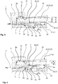
- Fig. 1 shows a fastening device 1 in a schematic, spatial representation according to a first embodiment.
- the fastening device 1 has a compensating means 2, in which Fig. 1 a first element 3 of the compensating means 2 is shown.
- the compensating means 2 also has a second element 4 ( Fig. 2 ) on.
- the fastening device 1 of the first exemplary embodiment furthermore has a support element 5 which comprises a jaw 6 on which a surface 15 and a stop 8a are configured.
- the surface 15 and the stop 8a are each flat and at least approximately oriented perpendicular to one another.
- a support area 7 ( Fig. 2 ) educated.
- the support region 7 on the jaw 6 of the support element 5 can, in a modified embodiment, also be formed in another way, in particular directly by a flat support surface 15 formed by the surface 15.
- the fastening device 1 also has fastening means 9, 10, 11.
- the first element 3 of the compensating means 2 has a part 12 and a pull tab 13. The pull tab 13 is bent by 90 ° with respect to the part 12.
- the first element 3 can be adjusted in a direction of adjustment 14 by a fitter on the pull tab 13.
- an opening can also be provided in the first element 3, which can be used, for example, to attach a screwdriver to adjust the first element 3 in the adjustment direction 14.
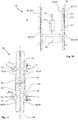
- Fig. 2 shows an elevator rail 20, which is fastened to a supporting structure 21 by means of fastening devices 1, 1A according to the first exemplary embodiment, in an excerpted, schematic sectional illustration.
- the elevator rail 20 has a rail foot 22 with a rail head 17, a first side 23 and a second side 24. Furthermore, 20 tracks 25, 26 are formed on the elevator rail, which serve as braking and / or guideways 25, 26.
- the fastening device 1 is used to fasten the first side 23 of the rail foot 22 to the supporting structure 21.
- the fastening device 1A is designed in accordance with the fastening device 1, which is used to fasten the second side 24 of the rail foot 22 to the supporting structure 21.
- the fastening devices 1, 1A are mounted opposite one another on the rail foot 22.
- a base plate 27 is provided.
- the base plate 27 forms a fastening plane 28.
- the base plate 27 is connected in a suitable manner to the support structure 21 or, together with the support structure, it forms a part that belongs together, for example a fastening angle.
- the second element 4 of the compensating means 2 of the fastening device 1 and a second element 4A of a compensating means 2A of the fastening device 1A are integrated in the base plate 27 in this exemplary embodiment.
- a type of fastening and a method for fastening the rail foot 22 of the elevator rail 20 according to the first exemplary embodiment is shown in FIG 3 and 4 described in more detail below.
- the assembly takes place in such a way that the fastening devices 1, 1A together fix the rail foot along the adjustment direction 14, 14A and in a guide direction 16 lying transversely to the adjustment direction 14, 14A, but a displacement of the rail foot 22 along a longitudinal axis 29 of the elevator rail 20 is made possible.
- the rail base 22 can be displaced relative to the fastening plane 28.
- Fig. 3 shows the in Fig. 2 III designated section of the fastening device 1 during the assembly of the elevator rail 20. Furthermore, the Fig. 4 the in Fig. 2 III marked section in the assembled state. Based on 3 and 4 the attachment to the first side 23 of the rail foot 22 is described. The attachment to the second side 24 of the rail foot 22 is carried out in a corresponding manner.
- Fig. 3 shows the first element 3 in an initial state specified for assembly.
- the second element 4 integrated in the base plate 27 has a recess 32, which is designed as a through opening 32 in this exemplary embodiment.
- a bent part 33 is in the starting position in the recess 32 of the second element 4.
- a wedge-shaped part 34 is formed on the bent part 33, the wedge-shaped part 34 having a sliding surface 35.
- the sliding surface 35 is assigned to an edge 36 of the second element 4.
- a rounded or beveled edge 36 can be provided in order to facilitate an adjustment of the first element 3 in the adjustment direction 14.
- an inclined surface in particular a sliding surface, can also be provided on the second element 4, which is assigned to the sliding surface 35 of the first element 3.
- the recess 32 is not designed as a through opening 32 but as a recess 32 in the second element 4.
- the support element 5 is fastened to the support structure 21, the first side 23 of the rail foot 22 being located partially between the jaw 6 of the support element 5 and the first element 3 resting on the base plate 27.
- the support element 5 is mounted in a fixed position with respect to the fastening plane, with a displacement of the rail foot 22 in the adjustment direction 14 due to the system the rail foot 22 is prevented.
- the support element 5 can be adjusted and fixed in such a way that the rail foot 22 is fixed in the adjustment direction 14 by means of the stop 8a.
- the support area 7 is in a possible embodiment, which in the 3 and 4 is shown, formed on the protrusion 37 on the surface 15 of the jaw 6. Furthermore, a projection 39 is formed on a part 38 of the first element 3, on which a contact area 40 is formed. Between the support area 7 and the contact area 40 there is a holding dimension 41 which is initially larger than a required holding dimension 42.
- the required holding dimension 42 is determined here by the geometry of the rail foot 22. Due to manufacturing-related tolerances, there are generally different holding masses 42 for different elevator rails 20, 20A ( Fig. 11 ) or for different foot areas of the elevator rails 20, 20A.
- the first element 3 is adjusted in the adjustment direction 14 until the in the Fig. 4 situation occurs, in which the holding dimension 41 between the support region 7 and the contact region 40 is equal to the required holding dimension 42, which is determined by the geometry of the rail foot 22.
- the first element 3 acts on the rail foot 22 against the jaw 6 of the support element 5.
- the first element 3 can be designed as a spring element 3.
- a possible prestressing force is limited in such a way that the desired displacement of the rail foot 22 along the longitudinal axis 29 of the elevator rail 20 is made possible.
- the first element 3 with the bent part 33 is designed as an essentially inelastic component.
- the holding dimension 41 can thus be adapted precisely and force-free to the geometry of the rail foot 22. This enables an almost disability-free longitudinal displacement of the rail foot 22 relative to the fastening plane 28.
- support area 7 and the contact area 40 and possibly also the stop 8a can be provided with sliding coatings in order to facilitate the longitudinal displacement of the rail foot 22 or to reduce a corresponding puncture force.
- a displacement s 11 is required in this embodiment.
- the first element 3 is actuated by this displacement s 11 in the adjustment direction 14 in order to achieve the fastening.
- the first element 3 slides along its edge 36 with its sliding surface 35 formed on the wedge-shaped part 34 until the in the Fig. 4 shown end position is reached.
- the first element 3 is in this position, for example, by means of the in FIG Fig. 1 shown fasteners 9, 10 fixed.
- Fig. 5 shows a possible intermediate layer 50 for a fastening device 1 according to a second embodiment in an excerpt spatial representation.
- the intermediate layer 50 preferably has a constant thickness 51.
- the intermediate layer 50 can be configured on its upper side 52 and / or its lower side 53 as a sliding side 52, 53.
- a configuration of the intermediate layer 50 or a coating on the upper side 52 and / or the lower side 53 with Teflon or other sliding coatings is possible.
- a side of the intermediate layer 50 facing the rail foot 22 can be arched (not shown), thereby preventing the rail fastening from being braced when the fastening plane 28 is inclined slightly.
- the intermediate layer 50 has a mounting groove 54 which is designed in such a way that the jaw 6 can be at least partially inserted into the mounting groove 54.
- a dimension 55 of the mounting groove results from a corresponding dimension 55 of the jaw 6 of the support element 5, which in Fig. 1 is shown.
- This will in the assembled state, which in the Fig. 6 a mounting of the mounting groove 54 from the jaw 6 that is as free of play as possible with respect to the longitudinal axis 29 is illustrated.
- the intermediate layer 50 can be made symmetrical, so that the upper side 52 or the lower side 53 can be exchanged. This prevents any incorrect assembly.
- Fig. 6 shows the fastening device 1 according to the second embodiment, the serves to fasten the first side 23 of the rail foot 22 of the elevator rail 20.
- the jaw 6 is configured accordingly in this exemplary embodiment, so that the additional thickness 51 of the intermediate layer 50 is taken into account.
- the projection 39 of the first element 3 lies against the underside 53 of the intermediate layer 50 in the assembled state.
- the top 52 of the intermediate layer 50 bears against a bottom 56 of the rail foot 22.
- the projection 37 of the jaw 6 of the support element 5 lies against an upper side 57 of the rail foot 22.
- the first exemplary embodiment shown is the top 57 of the rail foot 22 directly against the support region 7 of the support element 5. Furthermore, the underside 56 of the rail foot 22 lies directly against the contact area 40 of the first element 3 of the compensating means 2.
- the rail foot 22 When using the 5 and 6 In the exemplary embodiment described, the rail foot 22, however, bears against the contact region 40 of the projection 39 of the first element 3 of the compensating means 2 by means of the intermediate layer 50.
- the bottom 56 of the rail base 22 slides along the top 52 of the intermediate layer 50 52 can be reduced.
- an indirect contact of the upper side 57 of the rail foot 22 on the support region 7 of the support element 5 is realized.
- an adjustment of the first element 3 or the contact with the contact area 40 of the first element 3 can be improved by the intermediate layer 50.
- the intermediate layer 50 prevents the position of the first element 3 from being changed when the rail foot 22 moves relative to the fastening device 1 due to forces acting along the longitudinal axis 29, since there is no relative movement between the projection 39 and the underside 53 of the intermediate layer 50 occurs.
- Fig. 7 shows fastening devices 1, 1A according to a third embodiment and a support structure 21 in a spatial representation, the fastening device 1A is partially shown.
- the fastening device 1 has the support element 5 screwed onto the base plate 27.
- the fastening device 1 has a first element 3, which is offset along the longitudinal axis 29 next to the support element 5, and a second element 4 integrated into the base plate 27.
- the fastening device 1A has the support element 5A and the second element 4A integrated in the base plate 27.
- the first element of the fastening device 1A is not shown.
- a wedge-shaped part 34 is formed on the first element 3, which moves when the first element 3 is adjusted in the adjustment direction 14 relative to the second element 4 or the base plate 27.
- the setting of the holding dimension 41 takes place as previously explained, in that when the first element 3 is adjusted in the adjustment direction 14, the wedge-shaped part 34 is adjusted via the recess 32 machined into the base plate 27 until the holding dimension 41 corresponds to the required holding dimension 42.
- the first element 3 is then fixed relative to the second element 4 via the fastening means 9.
- the first side 23 of the rail foot 22 can be pressed against the support region 7 of the support element 5 in order to fasten the first side 23 of the rail foot 22.
- the second side 24 of the rail foot 22 is fastened with the fastening device 1A.
- the base plate 27 is designed to be L-shaped and screwed to the support structure 21 on one side 58.
- the mounting level 28 is located on the base plate 27.
- the mounting level 28 is characterized in that it is stationary with respect to the supporting structure 21.
- the fastening means 9, 11, 11A allow the supporting elements 5, 5A and the first elements 3 of the compensating means 2, 2A to be fixed or fixed with respect to the fastening plane 28, the first element of the compensating means 2A not being shown.
- Fixed arrangement of the fastening level 28 with respect to the supporting structure 21 means that the base plate 27 can be adjusted with the fastening level 28 in relation to the supporting structure 21, so that inaccuracies in the building can be leveled out by aligning the base plate 27 during assembly. After adjustment, the base plate 27 is screwed to the support structure 21, for example, so that the fastening plane 28 is stationary with respect to the support structure 21.
- Fig. 8 shows a fastening device 1 according to a fourth embodiment in a spatial exploded view.
- the support element 5 itself is designed as a compensating means 2.
- a stop 8 is formed on the second element 4 of the compensating means 2. By positioning the second element 4 and the corresponding stop 8, the rail foot is positioned in the direction of the adjustment direction 14.
- the first element 3 is at least partially inserted into the second element 4, a wedge-shaped part 34 of the first element 3 abutting a wedge-shaped part 60 of the second element 4.
- the system is preferably carried out on inclined surfaces 35, 61 which are designed as first and second sliding surfaces 35, 61.
- a projection 62 in particular a cuboid or lip-shaped projection 62, is formed on the first element 3, the support region 7 being formed on a projection 37 provided on the projection 62.
- the one in the representation of the Fig. 8 hidden projection 37 may, for example, correspond to that in FIG Fig. 3 projection 37 shown may be formed.
- the support region can also be designed in the form of a support surface 15 formed on the projection 62.
- a fastening means 11 is provided, which can be formed, for example, from a screw and a nut.
- a passage in the first element 3 for the passage of the fastening means 11 is designed as an elongated hole, so that the first element 3 can be displaced in relation to the second element 4.
- the elongated hole or the passage opening 75 can also be provided in the second element 4.
- Fig. 9 shows the elevator rail 20 which is fastened by means of the fastening devices 1, 1A to a fastening plane 28 or to the supporting structure 21.
- the rail base 22 is supported on rounded heads 63, 64 by screw elements 65, 66. Standard screws with semicircular heads can be used. Define the rounded heads 63, 64 of the screw elements 65, 66 the contact area 40. In this case, a direct contact of the underside of the rail foot 56 with the contact area 40 is provided.
- an indirect system can also be provided, for example that in FIG Fig. 5 Intermediate layer 50 shown can be used in a correspondingly modified embodiment.
- the compensating means 2 and at the same time the supporting element 5 are realized by the first and second elements 3, 4, wherein, as previously stated, the rail foot can be positioned in the direction of the adjustment direction 14 by positioning the second element 4 and the corresponding stop 8a. Corresponding slots are provided in the base plate 27 for this purpose.
- the projection 62 with the support region 7 can be lowered, as is illustrated by an arrow 67. This reduces the holding dimension 41 to the required holding dimension 42.
- the fastening means 11 is then tightened, as is illustrated by an arrow 68, so that the two elements 3, 4 of the compensating means 2 are fixed to one another and with respect to the fastening plane 28.
- an intermediate piece 69 can also be provided in order to increase a possible holding dimension 41. If necessary, the first sliding surface 35 and the second sliding surface 61 can be roughened to prevent unintentional adjustment during later operation.
- the second side 24 of the rail foot 22 is fastened in a corresponding manner by means of the fastening device 1A.
- Fig. 10 shows an elevator system 100 in a partial, schematic representation according to a possible embodiment of the invention.
- the elevator installation 100 has a plurality of elevator rails 20, 20A, 20B, 20C.
- the elevator rails 20, 20A are part of an arrangement 80 of a plurality of elevator rails 20, 20A, which extend along a longitudinal axis 29 through the elevator shaft 81.
- tracks 25, 26 are formed which serve as braking and / or guideways 25, 26 for an elevator car 82.
- further arrangements of elevator rails can be provided.
- a further arrangement 83 with the elevator rails 20B, 20C is shown as an example, which also serves for the elevator car 82.
- Further such arrangements of elevator rails can be provided for a counterweight 84.
- the Counterweight 84 is connected to the elevator car 82 via a suspension element 85.
- Fig. 11 shows the in Fig. 10 XIII section of the arrangement 80 from the elevator rails 20, 20A to explain a possible embodiment of the invention.
- the arrangement 80 here consists of a plurality of elevator rails 20, 20A, of which only the elevator rails 20, 20A are shown in extracts.
- the elevator rails 20, 20A are arranged along a longitudinal axis 29 and abut one another at an interface 85. At the interface 85, the elevator rails 20, 20A are joined together by means of connecting straps 89.
- uninterrupted tracks 25, 26 are formed on the arrangement 80 from the elevator rails 20, 20A.
- the elevator rail 20 has the rail foot 22 with the first side 23 and the second side 24.
- the elevator rail 20A has a rail foot 86 with a first side 87 and a second side 88.
- a suitable number of fastening devices is used to fasten the elevator rails 20, 20A, fastening devices 1, 1A, 1B, 1C being shown schematically.
- the displacement s 11 enables the first side 23 of the rail foot 22 of the elevator rail 20 to be fastened by means of the fastening device 1.
- a displacement s 12 is used for fastening the second side 24 of the elevator rail 20.
- the displacement s 11 and the displacement s 12 can be the same, but also different.
- a displacement s 21 is carried out on the fastening device 1B for fastening the first side 87 of the rail foot 86.
- the displacement s 21 differs from the displacement s 11 because, for example, there are manufacturing tolerances between the individual elevator rails 20, 20A which lead to different values for the required holding dimension 42 ( Fig. 3 ) to lead.
Landscapes
- Lift-Guide Devices, And Elevator Ropes And Cables (AREA)
Claims (10)
- Dispositif de fixation (1), qui sert à la fixation d'un côté (23) d'un pied de rail (22) d'un rail d'ascenseur (20) par rapport à un plan de fixation (28), comportant une région de support (7) et une région d'appui (40) entre lesquelles le côté (23) du pied de rail (22) peut être disposé, la région d'appui (40) étant orientée vers un côté inférieur (56) du pied de rail (22) et la région de support (7) étant orientée vers un côté supérieur (57) du pied de rail (22), un moyen de compensation (2) étant prévu, ledit moyen de compensation (2) comprenant un premier élément (3) et un second élément (4) qui sont déplaçables l'un par rapport à l'autre le long d'une direction de déplacement (14) servant à la fixation du côté (23) du pied de rail (22) du rail d'ascenseur (20), le premier élément (3) et le second élément (4) étant conçus de telle sorte qu'entre la région d'appui (40) et la région de support (7), une masse de retenue (41), considérée perpendiculairement à la direction de déplacement (14), au niveau de laquelle une fixation sans jeu d'un côté d'un pied de rail entre la région d'appui (40) et la région de support (7) est rendue possible, peut être modifiée par un déplacement du premier élément (3) par rapport au second élément (4), s'effectuant dans la direction de déplacement (14), et la région de support (7) étant réalisée sur le premier élément (3) et/ou la région de support (7) étant réalisée sur au moins une saillie (62) réalisée sur le premier élément (3),
caractérisé en ce
qu'au moins une première surface de glissement (35) est réalisée au niveau du premier élément (3), laquelle première surface de glissement présente une inclinaison constante par rapport à la direction de déplacement (14), et en ce qu'une seconde surface de glissement (61) est réalisée au niveau du second élément (4), laquelle seconde surface de glissement présente une inclinaison constante par rapport à la direction de déplacement (14). - Dispositif de fixation selon la revendication 1, caractérisé en ce que l'inclinaison de la seconde surface de glissement (61) correspond à l'inclinaison de la première surface de glissement (35) et/ou en ce que la première surface de glissement (35) coopère avec la seconde surface de glissement pour régler la masse de retenue (41).
- Dispositif de fixation selon l'une des revendications 1 ou 2, caractérisé en ce qu'un élément de support (5) est prévu, lequel élément de support comprend le premier élément (3) doté de la région de support (7), et le second élément (4), au moins une butée (8) étant réalisée au niveau du second élément (4).
- Dispositif de fixation selon la revendication 3, caractérisé en ce que la butée (8) positionne le pied de rail dans le sens de la direction de déplacement (14).
- Dispositif de fixation selon la revendication 3 ou 4, caractérisé en ce que l'élément de support (5) présente une ouverture de passage (75) ou une rainure s'étendant à travers l'élément de support (5) le long de la direction de déplacement (14), et en ce qu'au moins le premier élément (3) est déplaçable le long de l'ouverture de passage (75) ou de la rainure de l'élément de support (5) pour la fixation du côté (23) du pied de rail (22).
- Dispositif de fixation selon l'une des revendications 1 à 5, caractérisé en ce qu'un contact direct du pied de rail (22) avec la région d'appui (40) et/ou avec la région de support (7) est rendu possible, ou en ce qu'une couche intermédiaire (50) est prévue, laquelle couche intermédiaire peut être disposée entre le pied de rail (22) et la région d'appui (40) et/ou la région de support (7) pour la fixation du côté (23) du pied de rail (22), la couche intermédiaire (50) présentant un côté de glissement (53) orienté vers la région d'appui (40) et/ou la région de support (7), et/ou la couche intermédiaire (50) présentant un côté de glissement (52) orienté vers le pied de rail (22).
- Dispositif de fixation selon l'une des revendications 1 à 6, caractérisé en ce que le second élément (4) destiné à la fixation du côté (23) du pied de rail (22) est relié à une plaque de base (27), ou en ce que le second élément (4) destiné à la fixation du côté (23) du pied de rail (22) repose sur une plaque de base (27).
- Installation d'ascenseur (100) comprenant au moins un agencement (80) de rails d'ascenseur (20, 20A) disposés en série le long d'un axe longitudinal (29) et plusieurs dispositifs de fixation (1, 1A, 1B, 1C), qui sont chacun réalisés selon l'une des revendications 1 à 7, les dispositifs de fixation (1, 1A, 1B, 1C) étant associés aux côtés (23, 24, 87, 88) des pieds de rail (22, 86) des rails d'ascenseur (20, 20A), et chacun desdits dispositifs de fixation (1, 1A, 1B, 1C) permettant un réglage de la masse de retenue (41) requise sur le côté (23, 24, 87, 88) associé du pied de rail du rail d'ascenseur (20, 20A) associé.
- Procédé de fixation d'un pied de rail (22) d'un rail d'ascenseur (20), lequel procédé est exécuté à l'aide d'au moins un dispositif de fixation (1) selon l'une des revendications 1 à 7, le dispositif de fixation (1) étant monté par rapport à un plan de fixation (28), et le pied de rail (22) étant fixé par rapport au plan de fixation (28) par le déplacement (s11) du premier élément (3) par rapport au second élément (4) dans la direction de déplacement (14).
- Procédé selon la revendication 9, caractérisé en ce qu'un premier dispositif de fixation (1) sur un premier côté (23) du pied de rail (22) et un second dispositif de fixation (1A) sur un second côté (23) du pied de rail (22) sont montés sur le pied de rail (22) de manière à se faire face, de sorte que le premier dispositif de fixation (1) et le second dispositif de fixation (1A) fixent le pied de rail (22) le long de la direction de déplacement (14), mais qu'un déplacement du pied de rail (22) le long d'un axe longitudinal (29) du rail d'ascenseur (20) soit rendu possible.
Applications Claiming Priority (2)
| Application Number | Priority Date | Filing Date | Title |
|---|---|---|---|
| EP15200951 | 2015-12-17 | ||
| PCT/EP2016/081305 WO2017103016A1 (fr) | 2015-12-17 | 2016-12-15 | Dispositifs de fixation servant à la fixation de rails d'ascenseur |
Publications (2)
| Publication Number | Publication Date |
|---|---|
| EP3390261A1 EP3390261A1 (fr) | 2018-10-24 |
| EP3390261B1 true EP3390261B1 (fr) | 2020-04-22 |
Family
ID=54979454
Family Applications (1)
| Application Number | Title | Priority Date | Filing Date |
|---|---|---|---|
| EP16812948.4A Active EP3390261B1 (fr) | 2015-12-17 | 2016-12-15 | Dispositifs de fixation de rails d'ascenseur |
Country Status (6)
| Country | Link |
|---|---|
| US (1) | US20180362299A1 (fr) |
| EP (1) | EP3390261B1 (fr) |
| CN (1) | CN108367893B (fr) |
| ES (1) | ES2789749T3 (fr) |
| HK (1) | HK1253297A1 (fr) |
| WO (1) | WO2017103016A1 (fr) |
Families Citing this family (9)
| Publication number | Priority date | Publication date | Assignee | Title |
|---|---|---|---|---|
| KR102213646B1 (ko) * | 2015-09-11 | 2021-02-08 | 미쓰비시덴키 가부시키가이샤 | 가이드 레일 고정 장치 |
| PL3390260T3 (pl) * | 2015-12-17 | 2021-02-08 | Inventio Ag | Moduł mocujący do mocowania szyn windy |
| WO2017108495A1 (fr) * | 2015-12-22 | 2017-06-29 | Inventio Ag | Pince de fixation de rail de guidage d'ascenseur |
| ES2727504B2 (es) * | 2018-04-16 | 2020-10-16 | S A De Vera Savera | Brida ajustable al espesor del ala de una guía de ascensor |
| DE102019204852B4 (de) * | 2019-04-04 | 2023-06-07 | Deckel Maho Pfronten Gmbh | Führungsvorrichtung, Präzisionsauflager für eine Linearschiene und Justierverfahren |
| AU2021220916A1 (en) * | 2020-02-11 | 2022-09-01 | Inventio Ag | Assembly apparatus for implementing assembly steps on a wall and method for arranging a magazine component on an assembly apparatus |
| CN111196541A (zh) * | 2020-03-18 | 2020-05-26 | 迅达(中国)电梯有限公司 | 电梯导轨固定装置 |
| CN113928954B (zh) * | 2021-11-01 | 2023-07-14 | 日立电梯(中国)有限公司 | 一种可调节夹紧力的导轨压码 |
| WO2024078719A1 (fr) * | 2022-10-13 | 2024-04-18 | Kone Corporation | Attache de fixation de rail de guidage, agencement de guidage d'ascenseur et procédé |
Family Cites Families (8)
| Publication number | Priority date | Publication date | Assignee | Title |
|---|---|---|---|---|
| US1925867A (en) * | 1931-11-21 | 1933-09-05 | Westinghouse Elec Elevator Co | Elevator guide-rail supporting device |
| US3982692A (en) * | 1974-07-19 | 1976-09-28 | R. Stahl Aufzuege Gmbh | Clamping means for elevator guide rails and the like |
| US4324360A (en) * | 1979-03-09 | 1982-04-13 | Otis Elevator Company | Elevator guide rail mounting arrangement |
| US6830133B2 (en) * | 2002-03-06 | 2004-12-14 | Terryle L. Sneed | Connector brackets |
| CN102795528B (zh) * | 2011-05-24 | 2015-06-10 | 三菱电机株式会社 | 电梯轨道的支承结构 |
| US20140000986A1 (en) * | 2012-06-28 | 2014-01-02 | Daniel Quinn | Device and method for fastening and aligning a guide rail |
| FR2996216B1 (fr) * | 2012-10-03 | 2015-04-17 | Sodimas | Fixation d'un guide d'ascenseur a une paroi |
| ES2557505B1 (es) * | 2014-07-24 | 2016-11-03 | S.A. De Vera (Savera) | Brida adaptable para guías de ascensor |
-
2016
- 2016-12-15 WO PCT/EP2016/081305 patent/WO2017103016A1/fr active Application Filing
- 2016-12-15 CN CN201680074006.0A patent/CN108367893B/zh not_active Expired - Fee Related
- 2016-12-15 US US16/063,343 patent/US20180362299A1/en not_active Abandoned
- 2016-12-15 ES ES16812948T patent/ES2789749T3/es active Active
- 2016-12-15 EP EP16812948.4A patent/EP3390261B1/fr active Active
-
2018
- 2018-10-02 HK HK18112589.2A patent/HK1253297A1/zh unknown
Non-Patent Citations (1)
| Title |
|---|
| None * |
Also Published As
| Publication number | Publication date |
|---|---|
| CN108367893B (zh) | 2020-04-28 |
| US20180362299A1 (en) | 2018-12-20 |
| EP3390261A1 (fr) | 2018-10-24 |
| CN108367893A (zh) | 2018-08-03 |
| HK1253297A1 (zh) | 2019-06-14 |
| ES2789749T3 (es) | 2020-10-26 |
| WO2017103016A1 (fr) | 2017-06-22 |
Similar Documents
| Publication | Publication Date | Title |
|---|---|---|
| EP3390261B1 (fr) | Dispositifs de fixation de rails d'ascenseur | |
| EP3390260B1 (fr) | Module de fixation de rails d'ascenseur | |
| WO2006092118A2 (fr) | Dispositif de blocage pour un siege de vehicule reglable | |
| EP2714568B1 (fr) | Couplage de porte de cabine-porte de cage variable | |
| EP3113891B1 (fr) | Coulisseau porte-outil | |
| EP2369056B1 (fr) | Système de fixation d'un rail et pièce d'adaptateur pour un tel système | |
| EP3551565A1 (fr) | Support de patin de rail pour fixer un rail d'une installation d'ascenseur | |
| EP2159345B1 (fr) | Fixation pour éléments de revêtement | |
| WO2012022282A2 (fr) | Élément de protection d'arête servant à l'agencement de modules pv sans cadre | |
| EP3381856A1 (fr) | Ensemble de fixation comprenant un élément de fixation pour fixer un rail d'un ascenseur dans une cage d'ascenseur | |
| EP3722527B1 (fr) | Dispositif de fixation permettant de fixer des éléments de façade d'une façade à éléments | |
| EP3612703B1 (fr) | Truelle de montage pour la pose de banquettes de fenêtre et procédé de montage d'une banquette de fenêtre avec cette truelle de montage | |
| EP3888495B1 (fr) | Dispositif d'extraction pour un tiroir extractable de deux côtés | |
| DE202011050739U1 (de) | System zum Befestigen einer Schiene auf einem Untergrund | |
| EP1845219A1 (fr) | Dispositif de support pour revêtements muraux | |
| EP4256159A1 (fr) | Ferrure de porte coulissante, et procédé d'installation d'une ferrure de porte coulissante | |
| EP3029236B1 (fr) | Ferrure d'angle réglable dotée d'un élément de retenue | |
| EP2369114B1 (fr) | Elément d'équilibrage pour un rail de guidage et procédé de montage de l'élément d'équilibrage | |
| WO2017103014A1 (fr) | Systèmes de fixation permettant de fixer des rails d'ascenseur | |
| EP3029235A1 (fr) | Ferrure d'angle destinée à l'agencement d'un élément de porte sur un pivot ou un axe | |
| DE102007045709B3 (de) | Betonschwelle und Verfahren zur Regulierung der Position von Schienen | |
| WO2016198339A1 (fr) | Dispositif de fixation pour rails | |
| AT413583B (de) | Stabilisierungsvorrichtung für möbelteile | |
| DE102017126777B4 (de) | System zum Verlegen von Dielen | |
| DE102017222375B4 (de) | Verfahren zum Toleranzausgleich und Toleranzausgleichsystem |
Legal Events
| Date | Code | Title | Description |
|---|---|---|---|
| STAA | Information on the status of an ep patent application or granted ep patent |
Free format text: STATUS: UNKNOWN |
|
| STAA | Information on the status of an ep patent application or granted ep patent |
Free format text: STATUS: THE INTERNATIONAL PUBLICATION HAS BEEN MADE |
|
| PUAI | Public reference made under article 153(3) epc to a published international application that has entered the european phase |
Free format text: ORIGINAL CODE: 0009012 |
|
| STAA | Information on the status of an ep patent application or granted ep patent |
Free format text: STATUS: REQUEST FOR EXAMINATION WAS MADE |
|
| 17P | Request for examination filed |
Effective date: 20180523 |
|
| AK | Designated contracting states |
Kind code of ref document: A1 Designated state(s): AL AT BE BG CH CY CZ DE DK EE ES FI FR GB GR HR HU IE IS IT LI LT LU LV MC MK MT NL NO PL PT RO RS SE SI SK SM TR |
|
| AX | Request for extension of the european patent |
Extension state: BA ME |
|
| DAV | Request for validation of the european patent (deleted) | ||
| DAX | Request for extension of the european patent (deleted) | ||
| GRAP | Despatch of communication of intention to grant a patent |
Free format text: ORIGINAL CODE: EPIDOSNIGR1 |
|
| STAA | Information on the status of an ep patent application or granted ep patent |
Free format text: STATUS: GRANT OF PATENT IS INTENDED |
|
| INTG | Intention to grant announced |
Effective date: 20191113 |
|
| GRAS | Grant fee paid |
Free format text: ORIGINAL CODE: EPIDOSNIGR3 |
|
| GRAA | (expected) grant |
Free format text: ORIGINAL CODE: 0009210 |
|
| STAA | Information on the status of an ep patent application or granted ep patent |
Free format text: STATUS: THE PATENT HAS BEEN GRANTED |
|
| AK | Designated contracting states |
Kind code of ref document: B1 Designated state(s): AL AT BE BG CH CY CZ DE DK EE ES FI FR GB GR HR HU IE IS IT LI LT LU LV MC MK MT NL NO PL PT RO RS SE SI SK SM TR |
|
| REG | Reference to a national code |
Ref country code: CH Ref legal event code: EP |
|
| REG | Reference to a national code |
Ref country code: DE Ref legal event code: R096 Ref document number: 502016009691 Country of ref document: DE |
|
| REG | Reference to a national code |
Ref country code: IE Ref legal event code: FG4D Free format text: LANGUAGE OF EP DOCUMENT: GERMAN |
|
| REG | Reference to a national code |
Ref country code: AT Ref legal event code: REF Ref document number: 1259833 Country of ref document: AT Kind code of ref document: T Effective date: 20200515 |
|
| REG | Reference to a national code |
Ref country code: LT Ref legal event code: MG4D |
|
| REG | Reference to a national code |
Ref country code: NL Ref legal event code: MP Effective date: 20200422 |
|
| REG | Reference to a national code |
Ref country code: ES Ref legal event code: FG2A Ref document number: 2789749 Country of ref document: ES Kind code of ref document: T3 Effective date: 20201026 |
|
| PG25 | Lapsed in a contracting state [announced via postgrant information from national office to epo] |
Ref country code: LT Free format text: LAPSE BECAUSE OF FAILURE TO SUBMIT A TRANSLATION OF THE DESCRIPTION OR TO PAY THE FEE WITHIN THE PRESCRIBED TIME-LIMIT Effective date: 20200422 Ref country code: SE Free format text: LAPSE BECAUSE OF FAILURE TO SUBMIT A TRANSLATION OF THE DESCRIPTION OR TO PAY THE FEE WITHIN THE PRESCRIBED TIME-LIMIT Effective date: 20200422 Ref country code: NL Free format text: LAPSE BECAUSE OF FAILURE TO SUBMIT A TRANSLATION OF THE DESCRIPTION OR TO PAY THE FEE WITHIN THE PRESCRIBED TIME-LIMIT Effective date: 20200422 Ref country code: NO Free format text: LAPSE BECAUSE OF FAILURE TO SUBMIT A TRANSLATION OF THE DESCRIPTION OR TO PAY THE FEE WITHIN THE PRESCRIBED TIME-LIMIT Effective date: 20200722 Ref country code: PT Free format text: LAPSE BECAUSE OF FAILURE TO SUBMIT A TRANSLATION OF THE DESCRIPTION OR TO PAY THE FEE WITHIN THE PRESCRIBED TIME-LIMIT Effective date: 20200824 Ref country code: IS Free format text: LAPSE BECAUSE OF FAILURE TO SUBMIT A TRANSLATION OF THE DESCRIPTION OR TO PAY THE FEE WITHIN THE PRESCRIBED TIME-LIMIT Effective date: 20200822 Ref country code: FI Free format text: LAPSE BECAUSE OF FAILURE TO SUBMIT A TRANSLATION OF THE DESCRIPTION OR TO PAY THE FEE WITHIN THE PRESCRIBED TIME-LIMIT Effective date: 20200422 Ref country code: GR Free format text: LAPSE BECAUSE OF FAILURE TO SUBMIT A TRANSLATION OF THE DESCRIPTION OR TO PAY THE FEE WITHIN THE PRESCRIBED TIME-LIMIT Effective date: 20200723 |
|
| PG25 | Lapsed in a contracting state [announced via postgrant information from national office to epo] |
Ref country code: HR Free format text: LAPSE BECAUSE OF FAILURE TO SUBMIT A TRANSLATION OF THE DESCRIPTION OR TO PAY THE FEE WITHIN THE PRESCRIBED TIME-LIMIT Effective date: 20200422 Ref country code: LV Free format text: LAPSE BECAUSE OF FAILURE TO SUBMIT A TRANSLATION OF THE DESCRIPTION OR TO PAY THE FEE WITHIN THE PRESCRIBED TIME-LIMIT Effective date: 20200422 Ref country code: BG Free format text: LAPSE BECAUSE OF FAILURE TO SUBMIT A TRANSLATION OF THE DESCRIPTION OR TO PAY THE FEE WITHIN THE PRESCRIBED TIME-LIMIT Effective date: 20200722 Ref country code: RS Free format text: LAPSE BECAUSE OF FAILURE TO SUBMIT A TRANSLATION OF THE DESCRIPTION OR TO PAY THE FEE WITHIN THE PRESCRIBED TIME-LIMIT Effective date: 20200422 |
|
| PG25 | Lapsed in a contracting state [announced via postgrant information from national office to epo] |
Ref country code: AL Free format text: LAPSE BECAUSE OF FAILURE TO SUBMIT A TRANSLATION OF THE DESCRIPTION OR TO PAY THE FEE WITHIN THE PRESCRIBED TIME-LIMIT Effective date: 20200422 |
|
| REG | Reference to a national code |
Ref country code: DE Ref legal event code: R097 Ref document number: 502016009691 Country of ref document: DE |
|
| PG25 | Lapsed in a contracting state [announced via postgrant information from national office to epo] |
Ref country code: RO Free format text: LAPSE BECAUSE OF FAILURE TO SUBMIT A TRANSLATION OF THE DESCRIPTION OR TO PAY THE FEE WITHIN THE PRESCRIBED TIME-LIMIT Effective date: 20200422 Ref country code: CZ Free format text: LAPSE BECAUSE OF FAILURE TO SUBMIT A TRANSLATION OF THE DESCRIPTION OR TO PAY THE FEE WITHIN THE PRESCRIBED TIME-LIMIT Effective date: 20200422 Ref country code: IT Free format text: LAPSE BECAUSE OF FAILURE TO SUBMIT A TRANSLATION OF THE DESCRIPTION OR TO PAY THE FEE WITHIN THE PRESCRIBED TIME-LIMIT Effective date: 20200422 Ref country code: SM Free format text: LAPSE BECAUSE OF FAILURE TO SUBMIT A TRANSLATION OF THE DESCRIPTION OR TO PAY THE FEE WITHIN THE PRESCRIBED TIME-LIMIT Effective date: 20200422 Ref country code: DK Free format text: LAPSE BECAUSE OF FAILURE TO SUBMIT A TRANSLATION OF THE DESCRIPTION OR TO PAY THE FEE WITHIN THE PRESCRIBED TIME-LIMIT Effective date: 20200422 Ref country code: EE Free format text: LAPSE BECAUSE OF FAILURE TO SUBMIT A TRANSLATION OF THE DESCRIPTION OR TO PAY THE FEE WITHIN THE PRESCRIBED TIME-LIMIT Effective date: 20200422 |
|
| PG25 | Lapsed in a contracting state [announced via postgrant information from national office to epo] |
Ref country code: SK Free format text: LAPSE BECAUSE OF FAILURE TO SUBMIT A TRANSLATION OF THE DESCRIPTION OR TO PAY THE FEE WITHIN THE PRESCRIBED TIME-LIMIT Effective date: 20200422 Ref country code: PL Free format text: LAPSE BECAUSE OF FAILURE TO SUBMIT A TRANSLATION OF THE DESCRIPTION OR TO PAY THE FEE WITHIN THE PRESCRIBED TIME-LIMIT Effective date: 20200422 |
|
| PLBE | No opposition filed within time limit |
Free format text: ORIGINAL CODE: 0009261 |
|
| STAA | Information on the status of an ep patent application or granted ep patent |
Free format text: STATUS: NO OPPOSITION FILED WITHIN TIME LIMIT |
|
| 26N | No opposition filed |
Effective date: 20210125 |
|
| PG25 | Lapsed in a contracting state [announced via postgrant information from national office to epo] |
Ref country code: SI Free format text: LAPSE BECAUSE OF FAILURE TO SUBMIT A TRANSLATION OF THE DESCRIPTION OR TO PAY THE FEE WITHIN THE PRESCRIBED TIME-LIMIT Effective date: 20200422 |
|
| REG | Reference to a national code |
Ref country code: DE Ref legal event code: R119 Ref document number: 502016009691 Country of ref document: DE |
|
| REG | Reference to a national code |
Ref country code: CH Ref legal event code: PL |
|
| GBPC | Gb: european patent ceased through non-payment of renewal fee |
Effective date: 20201215 |
|
| PG25 | Lapsed in a contracting state [announced via postgrant information from national office to epo] |
Ref country code: MC Free format text: LAPSE BECAUSE OF FAILURE TO SUBMIT A TRANSLATION OF THE DESCRIPTION OR TO PAY THE FEE WITHIN THE PRESCRIBED TIME-LIMIT Effective date: 20200422 |
|
| REG | Reference to a national code |
Ref country code: BE Ref legal event code: MM Effective date: 20201231 |
|
| PG25 | Lapsed in a contracting state [announced via postgrant information from national office to epo] |
Ref country code: IE Free format text: LAPSE BECAUSE OF NON-PAYMENT OF DUE FEES Effective date: 20201215 Ref country code: FR Free format text: LAPSE BECAUSE OF NON-PAYMENT OF DUE FEES Effective date: 20201231 Ref country code: LU Free format text: LAPSE BECAUSE OF NON-PAYMENT OF DUE FEES Effective date: 20201215 |
|
| PG25 | Lapsed in a contracting state [announced via postgrant information from national office to epo] |
Ref country code: CH Free format text: LAPSE BECAUSE OF NON-PAYMENT OF DUE FEES Effective date: 20201231 Ref country code: DE Free format text: LAPSE BECAUSE OF NON-PAYMENT OF DUE FEES Effective date: 20210701 Ref country code: LI Free format text: LAPSE BECAUSE OF NON-PAYMENT OF DUE FEES Effective date: 20201231 Ref country code: GB Free format text: LAPSE BECAUSE OF NON-PAYMENT OF DUE FEES Effective date: 20201215 |
|
| REG | Reference to a national code |
Ref country code: ES Ref legal event code: FD2A Effective date: 20220207 |
|
| PG25 | Lapsed in a contracting state [announced via postgrant information from national office to epo] |
Ref country code: TR Free format text: LAPSE BECAUSE OF FAILURE TO SUBMIT A TRANSLATION OF THE DESCRIPTION OR TO PAY THE FEE WITHIN THE PRESCRIBED TIME-LIMIT Effective date: 20200422 Ref country code: MT Free format text: LAPSE BECAUSE OF FAILURE TO SUBMIT A TRANSLATION OF THE DESCRIPTION OR TO PAY THE FEE WITHIN THE PRESCRIBED TIME-LIMIT Effective date: 20200422 Ref country code: ES Free format text: LAPSE BECAUSE OF NON-PAYMENT OF DUE FEES Effective date: 20201216 Ref country code: CY Free format text: LAPSE BECAUSE OF FAILURE TO SUBMIT A TRANSLATION OF THE DESCRIPTION OR TO PAY THE FEE WITHIN THE PRESCRIBED TIME-LIMIT Effective date: 20200422 |
|
| PG25 | Lapsed in a contracting state [announced via postgrant information from national office to epo] |
Ref country code: MK Free format text: LAPSE BECAUSE OF FAILURE TO SUBMIT A TRANSLATION OF THE DESCRIPTION OR TO PAY THE FEE WITHIN THE PRESCRIBED TIME-LIMIT Effective date: 20200422 |
|
| PG25 | Lapsed in a contracting state [announced via postgrant information from national office to epo] |
Ref country code: BE Free format text: LAPSE BECAUSE OF NON-PAYMENT OF DUE FEES Effective date: 20201231 |
|
| REG | Reference to a national code |
Ref country code: AT Ref legal event code: MM01 Ref document number: 1259833 Country of ref document: AT Kind code of ref document: T Effective date: 20211215 |
|
| PG25 | Lapsed in a contracting state [announced via postgrant information from national office to epo] |
Ref country code: AT Free format text: LAPSE BECAUSE OF NON-PAYMENT OF DUE FEES Effective date: 20211215 |