EP3389131B1 - Bleiakkumulator - Google Patents
Bleiakkumulator Download PDFInfo
- Publication number
- EP3389131B1 EP3389131B1 EP16873037.2A EP16873037A EP3389131B1 EP 3389131 B1 EP3389131 B1 EP 3389131B1 EP 16873037 A EP16873037 A EP 16873037A EP 3389131 B1 EP3389131 B1 EP 3389131B1
- Authority
- EP
- European Patent Office
- Prior art keywords
- negative electrode
- positive electrode
- electrode material
- electrode plate
- storage battery
- Prior art date
- Legal status (The legal status is an assumption and is not a legal conclusion. Google has not performed a legal analysis and makes no representation as to the accuracy of the status listed.)
- Active
Links
Images


Classifications
-
- H—ELECTRICITY
- H01—ELECTRIC ELEMENTS
- H01M—PROCESSES OR MEANS, e.g. BATTERIES, FOR THE DIRECT CONVERSION OF CHEMICAL ENERGY INTO ELECTRICAL ENERGY
- H01M4/00—Electrodes
- H01M4/02—Electrodes composed of, or comprising, active material
- H01M4/14—Electrodes for lead-acid accumulators
-
- H—ELECTRICITY
- H01—ELECTRIC ELEMENTS
- H01M—PROCESSES OR MEANS, e.g. BATTERIES, FOR THE DIRECT CONVERSION OF CHEMICAL ENERGY INTO ELECTRICAL ENERGY
- H01M50/00—Constructional details or processes of manufacture of the non-active parts of electrochemical cells other than fuel cells, e.g. hybrid cells
- H01M50/40—Separators; Membranes; Diaphragms; Spacing elements inside cells
- H01M50/463—Separators, membranes or diaphragms characterised by their shape
- H01M50/466—U-shaped, bag-shaped or folded
-
- H—ELECTRICITY
- H01—ELECTRIC ELEMENTS
- H01M—PROCESSES OR MEANS, e.g. BATTERIES, FOR THE DIRECT CONVERSION OF CHEMICAL ENERGY INTO ELECTRICAL ENERGY
- H01M10/00—Secondary cells; Manufacture thereof
- H01M10/06—Lead-acid accumulators
-
- H—ELECTRICITY
- H01—ELECTRIC ELEMENTS
- H01M—PROCESSES OR MEANS, e.g. BATTERIES, FOR THE DIRECT CONVERSION OF CHEMICAL ENERGY INTO ELECTRICAL ENERGY
- H01M10/00—Secondary cells; Manufacture thereof
- H01M10/06—Lead-acid accumulators
- H01M10/08—Selection of materials as electrolytes
-
- H—ELECTRICITY
- H01—ELECTRIC ELEMENTS
- H01M—PROCESSES OR MEANS, e.g. BATTERIES, FOR THE DIRECT CONVERSION OF CHEMICAL ENERGY INTO ELECTRICAL ENERGY
- H01M10/00—Secondary cells; Manufacture thereof
- H01M10/06—Lead-acid accumulators
- H01M10/12—Construction or manufacture
-
- H—ELECTRICITY
- H01—ELECTRIC ELEMENTS
- H01M—PROCESSES OR MEANS, e.g. BATTERIES, FOR THE DIRECT CONVERSION OF CHEMICAL ENERGY INTO ELECTRICAL ENERGY
- H01M4/00—Electrodes
- H01M4/02—Electrodes composed of, or comprising, active material
- H01M4/62—Selection of inactive substances as ingredients for active masses, e.g. binders, fillers
- H01M4/624—Electric conductive fillers
- H01M4/625—Carbon or graphite
-
- H—ELECTRICITY
- H01—ELECTRIC ELEMENTS
- H01M—PROCESSES OR MEANS, e.g. BATTERIES, FOR THE DIRECT CONVERSION OF CHEMICAL ENERGY INTO ELECTRICAL ENERGY
- H01M4/00—Electrodes
- H01M4/02—Electrodes composed of, or comprising, active material
- H01M4/64—Carriers or collectors
- H01M4/66—Selection of materials
- H01M4/665—Composites
- H01M4/667—Composites in the form of layers, e.g. coatings
-
- H—ELECTRICITY
- H01—ELECTRIC ELEMENTS
- H01M—PROCESSES OR MEANS, e.g. BATTERIES, FOR THE DIRECT CONVERSION OF CHEMICAL ENERGY INTO ELECTRICAL ENERGY
- H01M4/00—Electrodes
- H01M4/02—Electrodes composed of, or comprising, active material
- H01M4/64—Carriers or collectors
- H01M4/66—Selection of materials
- H01M4/68—Selection of materials for use in lead-acid accumulators
-
- H—ELECTRICITY
- H01—ELECTRIC ELEMENTS
- H01M—PROCESSES OR MEANS, e.g. BATTERIES, FOR THE DIRECT CONVERSION OF CHEMICAL ENERGY INTO ELECTRICAL ENERGY
- H01M4/00—Electrodes
- H01M4/02—Electrodes composed of, or comprising, active material
- H01M4/64—Carriers or collectors
- H01M4/70—Carriers or collectors characterised by shape or form
- H01M4/72—Grids
- H01M4/73—Grids for lead-acid accumulators, e.g. frame plates
-
- H—ELECTRICITY
- H01—ELECTRIC ELEMENTS
- H01M—PROCESSES OR MEANS, e.g. BATTERIES, FOR THE DIRECT CONVERSION OF CHEMICAL ENERGY INTO ELECTRICAL ENERGY
- H01M50/00—Constructional details or processes of manufacture of the non-active parts of electrochemical cells other than fuel cells, e.g. hybrid cells
- H01M50/40—Separators; Membranes; Diaphragms; Spacing elements inside cells
- H01M50/409—Separators, membranes or diaphragms characterised by the material
- H01M50/44—Fibrous material
-
- H—ELECTRICITY
- H01—ELECTRIC ELEMENTS
- H01M—PROCESSES OR MEANS, e.g. BATTERIES, FOR THE DIRECT CONVERSION OF CHEMICAL ENERGY INTO ELECTRICAL ENERGY
- H01M4/00—Electrodes
- H01M4/02—Electrodes composed of, or comprising, active material
- H01M2004/021—Physical characteristics, e.g. porosity, surface area
-
- H—ELECTRICITY
- H01—ELECTRIC ELEMENTS
- H01M—PROCESSES OR MEANS, e.g. BATTERIES, FOR THE DIRECT CONVERSION OF CHEMICAL ENERGY INTO ELECTRICAL ENERGY
- H01M2300/00—Electrolytes
- H01M2300/0002—Aqueous electrolytes
- H01M2300/0005—Acid electrolytes
- H01M2300/0011—Sulfuric acid-based
-
- H—ELECTRICITY
- H01—ELECTRIC ELEMENTS
- H01M—PROCESSES OR MEANS, e.g. BATTERIES, FOR THE DIRECT CONVERSION OF CHEMICAL ENERGY INTO ELECTRICAL ENERGY
- H01M4/00—Electrodes
- H01M4/02—Electrodes composed of, or comprising, active material
- H01M4/62—Selection of inactive substances as ingredients for active masses, e.g. binders, fillers
- H01M4/621—Binders
- H01M4/622—Binders being polymers
-
- H—ELECTRICITY
- H01—ELECTRIC ELEMENTS
- H01M—PROCESSES OR MEANS, e.g. BATTERIES, FOR THE DIRECT CONVERSION OF CHEMICAL ENERGY INTO ELECTRICAL ENERGY
- H01M4/00—Electrodes
- H01M4/02—Electrodes composed of, or comprising, active material
- H01M4/62—Selection of inactive substances as ingredients for active masses, e.g. binders, fillers
- H01M4/628—Inhibitors, e.g. gassing inhibitors, corrosion inhibitors
-
- Y—GENERAL TAGGING OF NEW TECHNOLOGICAL DEVELOPMENTS; GENERAL TAGGING OF CROSS-SECTIONAL TECHNOLOGIES SPANNING OVER SEVERAL SECTIONS OF THE IPC; TECHNICAL SUBJECTS COVERED BY FORMER USPC CROSS-REFERENCE ART COLLECTIONS [XRACs] AND DIGESTS
- Y02—TECHNOLOGIES OR APPLICATIONS FOR MITIGATION OR ADAPTATION AGAINST CLIMATE CHANGE
- Y02E—REDUCTION OF GREENHOUSE GAS [GHG] EMISSIONS, RELATED TO ENERGY GENERATION, TRANSMISSION OR DISTRIBUTION
- Y02E60/00—Enabling technologies; Technologies with a potential or indirect contribution to GHG emissions mitigation
- Y02E60/10—Energy storage using batteries
-
- Y—GENERAL TAGGING OF NEW TECHNOLOGICAL DEVELOPMENTS; GENERAL TAGGING OF CROSS-SECTIONAL TECHNOLOGIES SPANNING OVER SEVERAL SECTIONS OF THE IPC; TECHNICAL SUBJECTS COVERED BY FORMER USPC CROSS-REFERENCE ART COLLECTIONS [XRACs] AND DIGESTS
- Y02—TECHNOLOGIES OR APPLICATIONS FOR MITIGATION OR ADAPTATION AGAINST CLIMATE CHANGE
- Y02P—CLIMATE CHANGE MITIGATION TECHNOLOGIES IN THE PRODUCTION OR PROCESSING OF GOODS
- Y02P70/00—Climate change mitigation technologies in the production process for final industrial or consumer products
- Y02P70/50—Manufacturing or production processes characterised by the final manufactured product
Definitions
- the present disclosure relates to a lead storage battery.
- Lead storage batteries are widely used for industrial and consumer applications, and the like, because they are excellent in reliability and are inexpensive. In particular, there have been many demands for use as vehicle batteries (so-called “batteries”). In recent years, as efforts to protect the environment and improve fuel cost, development of an idling stop system vehicle (hereinafter referred to as an "ISS vehicle”) which stops an engine during temporary stopping of a vehicle and re-starts the engine upon starting has been accelerated.
- ISS vehicle an idling stop system vehicle
- Lead storage batteries installed in ISS vehicles are mainly used in a state in which they are not completely charged, namely, a partial state of charge (PSOC) due to the following circumstances peculiar to ISS vehicles.
- PSOC partial state of charge
- engine starting and engine stopping are repeated frequently in ISS vehicles. Since a large electric current discharge is needed in starting an engine, the number of discharges increases as a necessity.
- an alternator that uses the engine as a power source also stops. Therefore, charging of the lead storage battery cannot be carried out. Since electric power supply to electric components (for example, an air-conditioner) is needed even during temporary stop, discharge load is increased.
- JP 4515902 B discloses a technology using a Pb-Ca alloy grid plate containing 0.6 to 2.0% by mass of Sn (tin) as a negative electrode grid plate, and using dilute sulfuric acid containing 2 to 50 g/L of Al (aluminum) in terms of sulfate as electrolytic solution.
- US 2015/200424 A1 discloses that, in a lead-acid battery including an electrode plate group housed in a cell chamber with an electrolyte, each positive electrode plate includes a positive electrode grid made of lead or a lead alloy containing no antimony, and a positive electrode active material with which the positive electrode grid is filled.
- Each negative electrode plate includes a negative electrode grid made of lead or a lead alloy containing no antimony, a surface layer formed on a surface of the negative electrode grid and made of a lead alloy containing antimony, and a negative electrode active material with which the negative electrode grid is filled.
- Patent Literature 1 can suppress thinning of an ear portion in a negative electrode current collector. Therefore, it is considered that the sudden life due to rupture of the ear portion can be delayed. However, in lead storage batteries used in ISS vehicles, generation control vehicles, and the like, further longer life is required. From such a viewpoint, the technology of Patent Literature 1 still had room for improvement.
- An object of the present disclosure is to provide a lead storage battery that can be used for a sufficiently long period of time even if the battery is mainly used in a partial state of charge (PSOC state).
- PSOC state partial state of charge
- the present invention relates to the lead storage battery of independent claim 1.
- a lead storage battery satisfying the conditions of the present invention can be used for a sufficiently long period of time even if it is mainly used in a PSOC state.
- the ratio p1/n1 of the mass p1 of the positive electrode material to the mass n1 of the negative electrode material is 1.35 or more, lead sulfate generated in the negative electrode ear portion is easily reduced to metallic lead. Therefore, it is possible to sufficiently suppress the decrease in thickness of the negative electrode ear portion over time (thinning of the ear portion). Consequently, it is possible to sufficiently prevent the occurrence of a situation in which the ear portion is ruptured and therefore output from the lead storage battery is suddenly stopped.
- the index of the life performance of a lead storage battery mainly used in the PSOC state includes "ISS cycle characteristics.” This can be evaluated by the cycle test that simulates the use of a lead storage battery in an ISS vehicle.
- one or a plurality of configurations selected from the following configurations may be employed.
- the negative electrode material may further contain a carbonaceous material.
- the carbonaceous material may be Ketjen black or scaly graphite.
- the separator may include a rib, and a base portion that supports the rib.
- the base portion may have a thickness of 0.3 mm or less, and the rib may have a height of 0.6 mm or less.
- the present disclosure provides a lead storage battery capable of being used for a sufficiently long period of time even if it is mainly used in a partial state of charge (PSOC state).
- PSOC state partial state of charge
- the term "layer” in the present specification encompasses not only the configuration of a shape formed on the entire surface, but also the configuration of a shape formed on a part of the surface, when the layer is observed in a plan view.
- the numerical range expressed by using “to” refers to the range including the numeric values before and after “to” as the minimum value and the maximum value, respectively.
- the upper or lower limit of the numerical range of a certain stage may be replaced with the upper or lower limit of the numerical range of another stage.
- the upper or lower limits of the numerical ranges thereof may be replaced with values described in Examples.
- “A or B" may contain any one of A and B, and may contain both A and B.
- the materials which are exemplified in the present specification can be used singly, or in combination of two or more thereof, unless otherwise specifically noted.
- the content of each of the components in the composition means the total amount of the plurality of substances which exist in the composition, unless otherwise specifically noted. Since the specific gravity varies depending on temperatures, in the present specification, the specific gravity is defined as one converted at 20 °C.
- a lead storage battery in accordance with this embodiment includes a battery case having a cell chamber; an electrode plate group being provided in the cell chamber, and including a separator, and a positive electrode plate and a negative electrode plate that are alternately stacked with the separator disposed therebetween; and an electrolytic solution accommodated in the cell chamber.
- the positive electrode plate and the negative electrode plate respectively include an electrode material filled portion made of electrode materials (a positive electrode material and a negative electrode material), a current collector that supports an electrode material filled portion, and an ear portion provided on an upper peripheral portion of the current collector.
- the electrode material contains, for example, an electrode active material.
- the ear portion is provided, for example, in such a manner that it protrudes upward from the upper peripheral portion of the current collector.
- S1/V1 is 8.9 cm -1 or more.
- p1 represents a mass of the positive electrode material and n1 represents a mass of the negative electrode material, p1/n1 is 1.35 or more.
- This lead storage battery can be applied to various types of lead storage batteries, that is, liquid lead storage batteries, valve regulated lead storage batteries, sealed lead storage batteries, and the like. Among them, from the viewpoint of manufacturing cost, and the like, a liquid lead storage battery is preferable.
- the electrode material indicates an electrode material after formation (for example, in a fully charged state). In an unformed stage, materials corresponding to the electrode material contain materials to become an electrode material by formation.
- FIG. 1 is a perspective view of a lead storage battery (liquid lead storage battery) in accordance with this embodiment.
- FIG. 2 is a view showing an inside structure of the lead storage battery 1.
- the lead storage battery 1 includes a battery case 2 which has an opening on the upper surface thereof and in which a plurality of an electrode plate groups 11 are stored, and a lid 3 for closing the opening of the battery case 2.
- the lid 3 is made of, for example, polypropylene, and includes a positive electrode terminal 4, a negative electrode terminal 5, and liquid port plugs 6 for blocking injection ports provided in the lid 3.
- the battery case 2 houses an electrolytic solution (not shown).
- An electrode plate group includes a separator and a positive electrode plate and a negative electrode plate that are alternately stacked with the separator disposed therebetween.
- the electrode plate group 11 includes, for example, a positive electrode plate 12, a negative electrode plate 13, a bag-shaped separator 14, a positive electrode-side strap 15, a negative electrode-side strap 16, an inter-cell connection portion 17 or an electrode pole 18.
- FIG. 4 is a front view showing an electrode plate (a positive electrode plate or a negative electrode plate).
- FIG. 5 is a sectional view taken on line V-V of FIG. 4 .
- FIG. 5(a) shows a cross-section of the positive electrode plate
- FIG. 5(b) shows a cross-section of the negative electrode plate.
- FIGs. 6 are front views of one example of a current collector (a positive electrode current collector or a negative electrode current collector).
- reference signs within parentheses show the configuration of a negative electrode plate.
- the number of the positive electrode plates 12 and the negative electrode plates 13 in the electrode plate group 11 may be, for example, seven positive electrode plates and eight negative electrode plates, eight positive electrode plates and eight negative electrode plates, or eight positive electrode plates and nine negative electrode plates. The more the numbers of the positive electrode plates and the negative electrode plates become, the more the ISS cycle characteristics are improved.
- the positive electrode plate 12 includes a positive electrode current collector 21 and a positive electrode material 23 filled into the positive electrode current collector 21.
- the positive electrode material 23 forms a positive electrode material filled portion 24.
- the positive electrode current collector 21 has a positive electrode current-collecting portion (positive electrode ear portion) 22.
- a portion filled with the positive electrode material 23 is the positive electrode material filled portion 24 (a sand-like hatching portion in FIG 4 ).
- the positive electrode material filled portion 24 is formed on the front and rear surfaces of the positive electrode plate 12.
- the entire surface of the positive electrode current collector 21 (the entire surface of the positive electrode material support portion mentioned later) is filled with the positive electrode material 23.
- the entire surface of the positive electrode current collector 21 is not necessarily filled with the positive electrode material 23.
- a portion that is not filled with the positive electrode material 23 may be included in a part of the positive electrode current collector 21.
- the positive electrode current collector 21 only a portion filled with the positive electrode material 23 becomes the positive electrode material filled portion 24, and a portion that is not filled with the positive electrode material 23 in the positive electrode current collector 21 is excluded from the positive electrode material filled portion 24.
- a positive electrode current collector 21 includes a positive electrode material support portion 21a, an upper frame portion (upper peripheral portion) 21b formed in a belt-shape on the upper side of the positive electrode material support portion 21a, and a positive electrode current-collecting portion (positive electrode ear portion) 22 provided on the upper frame portion 21b.
- the positive electrode current-collecting portion 22 is provided so as, for example, to partially protrude upward from the upper frame portion 21b.
- the outer shape of the positive electrode material support portion 21a is, for example, rectangular (rectangular or square), and formed in a grid shape.
- the positive electrode material support portion 21a may have a shape whose corners at the lower portion are cut off as shown in FIG. 6(b) .
- the positive electrode current collector 21 constitutes a conduction path of an electric current from the positive electrode material 23.
- a width W2 of the positive electrode current collector 21 is, for example, 10.0 to 16.0 cm.
- a height H2 of the positive electrode current collector 21 is, for example, 10.0 to 12.0 cm.
- a thickness of the positive electrode current collector 21 is, for example, 0.6 to 1.1 mm. Note here that when the positive electrode material support portion 21a has a shape whose corners at the lower portion are cut off, W2 and H2 are calculated assuming that the corners at the lower portion are present (see FIG. 6(b) ).
- Examples of the composition of the positive electrode current collector 21 include a lead-calcium-tin alloy, a lead-calcium alloy and a lead-antimony alloy. These lead alloys are formed into a grid shape by a gravity casting method, an expansion method, a punching method, or the like, to obtain the positive electrode current collector 21. Note here that the positive electrode current collector 21 shown in FIG. 6 is an expanded grid body.
- the positive electrode material 23 contains, for example, a positive electrode active material.
- the positive electrode material 23 is obtained by aging and drying, for example, a positive electrode material paste including a material to be formed into a positive electrode active material by formation (a raw material of the positive electrode active material), followed by formation.
- Examples of the positive electrode active material include ⁇ -lead dioxide ( ⁇ -PbO 2 ) and ⁇ -lead dioxide ( ⁇ -PbO 2 ). One of them may be included in the positive electrode material 23, or both of them may be included in the positive electrode material 23.
- the raw material of the positive electrode active material is not particularly limited, and examples thereof include lead powder.
- the lead powder examples include lead powder which is produced by a ball mill type lead powder producing machine or a Burton-pot type lead powder producing machine (a mixture of a main component PbO powder and scaly metallic lead, in the ball mill type lead powder producing machine).
- a ball mill type lead powder producing machine or a Burton-pot type lead powder producing machine (a mixture of a main component PbO powder and scaly metallic lead, in the ball mill type lead powder producing machine).
- red lead Pb 3 O 4
- the positive electrode material paste is only required to contain tribasic lead sulfate (a raw material of a positive electrode active material) as a main component.
- the content of the positive electrode active material (on the basis of the total mass of the positive electrode material 23) is preferably, for example, 95% by mass or more, and may be 97% by mass or more or 99% by mass or more.
- the upper limit of the content of the positive electrode active material may be, for example, 100% by mass.
- the positive electrode material 23 may be substantially made of positive electrode active material. Note here that the content of the positive electrode active material used herein represents the amount of the positive electrode active material (which has been subjected to formation) included in the positive electrode material 23 (which has been subjected to formation).
- the positive electrode material 23 may further contain additives.
- the additives include a carbonaceous material (a carbonaceous electrically conductive material), short fiber for reinforcement, and the like.
- the carbonaceous material include carbon black, graphite, and the like.
- the carbon black include furnace black (Ketjen black etc.), channel black, acetylene black, thermal black, and the like.
- the short fiber for reinforcement include acrylic fiber, polyethylene fiber, polypropylene fiber, polyethylene terephthalate fiber, carbon fiber, and the like. Note here that the carbon fiber exemplified as the short fiber for reinforcement may be added to the positive electrode material as the carbonaceous material (carbonaceous electrically conductive material).
- the lower limit of the specific surface area of the positive electrode material 23 is, for example, 3 m 2 /g, and may be 4m 2 /g or 5 m 2 /g from the viewpoint of being excellent in charge acceptance and having further excellence in ISS cycle characteristics.
- the upper limit of the specific surface area of the positive electrode material 23 is not particularly limited, but from a practical viewpoint and from the viewpoint of an excellent utilization rate, the upper limit is, for example, 15 m 2 /g, and may be 12 m 2 /g or 7 m 2 /g. From these viewpoints, the specific surface area of the positive electrode material 23 is, for example, 3 to 15 m 2 /g, and may be 4 to 12 m 2 /g or 5 to 7 m 2 /g.
- the specific surface area of the positive electrode material 23 herein represents the specific surface area of the positive electrode material 23 (after formation).
- the specific surface area of the positive electrode material 23 can be adjusted by, for example, a method for adjusting the additive amount of sulfuric acid and water when the positive electrode material paste is produced, a method for making the raw material of the active material be fine in an unformed stage, or a method for changing the formation conditions. It is not clear why the above-mentioned range of the specific surface area of the positive electrode material 23 achieves more excellent ISS cycle characteristics. However, the present inventors suppose as follows. In other words, the above-mentioned range of the specific surface area of the positive electrode material 23 contributes to keeping the state of charge (SOC) of the lead storage battery 1 relatively high.
- SOC state of charge
- a negative electrode active material can be sufficiently reduced easily. Therefore, a negative electrode current-collecting portion (negative electrode ear portion) 32 may not easily become lead sulfate. As a result, it is supposed that the deterioration of the negative electrode current-collecting portion 32 (thinning of an ear portion) can be suppressed, thus achieving more excellent ISS cycle characteristics.
- the specific surface area of the positive electrode material 23 can be measured by, for example, a BET method.
- the BET method is a general measurement technique for measuring specific surface area in which one inert gas whose molecular size is known (for example, nitrogen gas) is adsorbed on the surface of the test sample to be measured, and surface area is calculated from the adsorption amount and the occupied area of the inert gas. Specifically, measurement is carried out based on the following BET formula.
- Formula (1) is modified (the numerator and denominator of the left side are divided by P) to obtain the following formula (2).
- Gas molecules for which the adsorption occupied surface area is known are adsorbed on the test sample for the total specific surface area used in the measurement, and the relationship between the adsorbed amount (V) and the relative pressure (P/P o ) is measured.
- the left side of formula (2) and P/P 0 are plotted using the measured V and P/P o .
- s represents the slope
- the following formula (3) is derived from formula (2).
- i represents the intercept
- the slope s are expressed in the following formulae (4) and (5), respectively.
- Formulae (4) and (5) are modified to obtain the following formulae (6) and (7), and the following formula (8) for calculating the monolayer adsorption amount V m is obtained.
- the adsorption amount V at a certain relative pressure P/P o is measured at several points, and the slope and intercept of the plotted line are calculated to obtain the monolayer adsorption amount V m .
- the total surface area S total (m 2 ) of a test sample is calculated from the following formula (9), and the specific surface area S (m 2 /g) is calculated from the total surface area S total in the following formula (10).
- N represents Avogadro's number
- a CS represents an adsorption cross-sectional area (m 2 )
- M represents a molecular weight.
- w represents an amount of the sample (g).
- the negative electrode plate 13 includes a negative electrode current collector 31, and a negative electrode material 33 filled in the negative electrode current collector 31.
- the negative electrode material 33 constitutes a negative electrode material filled portion 34.
- the negative electrode current collector 31 includes a negative electrode current-collecting portion (a negative electrode ear portion) 32.
- a portion filled with negative electrode material 33 serves as the negative electrode material filled portion 34.
- the details of the negative electrode material filled portion 34 are the same as those of the positive electrode material filled portion 24.
- the negative electrode current collector 31 includes a negative electrode material support portion 31a, an upper frame portion (upper peripheral portion) 31b formed in a belt-shape on the upper side of the negative electrode material support portion 31a, and a negative electrode current-collecting portion (a negative electrode ear portion) 32 provided on the upper frame portion 31b.
- the negative electrode current-collecting portion 32 is provided so as, for example, to partially protrude upward from the upper frame portion 31b.
- the outer shape of the negative electrode material support portion 31a is, for example, rectangular (rectangular or square), and formed in a grid shape.
- the negative electrode material support portion 31a may have a shape whose corners at the lower portion are cut off as shown in FIG 6(b) .
- the negative electrode current collector 31 constitutes a conduction path to the negative electrode material 33.
- the composition of the negative electrode current collector 31 may be similar to that of the positive electrode current collector 21.
- the negative electrode current collector 31 can be produced by the same method as in the positive electrode current collector 21.
- the thickness d of the negative electrode current-collecting portion 32 is, for example, 0.6 mm or more, and may be 0.7 mm or more, 0.8 mm or more, 0.85 mm or more, 0.90 mm or more, 0.95 mm or more, or 1.0 mm or more.
- the thickness of the negative electrode current-collecting portion 32 may be, for example, 1.1 mm or less from the viewpoint of reducing the weight of the lead storage battery.
- the width W2, height H2, and thickness of the negative electrode current collector 31 may be the same or not the same as those of the positive electrode current collector 21. Note here that when the negative electrode material support portion 31a has a shape whose corners at the lower portion are cut off, W2 and H2 are calculated assuming that the corners at the lower portion are present (see FIG 6(b) ).
- the negative electrode material 33 contains, for example, a negative electrode active material.
- the negative electrode material 33 is obtained by aging and drying, for example, a negative electrode material paste including a material to be formed into a negative electrode active material by formation (a raw material of the negative electrode active material), followed by formation.
- the negative electrode active material include Spongylead and the like. The Spongylead tends to react with sulfuric acid in an electrolytic solution and gradually changes into lead sulfate (PbSO 4 ).
- Examples of the raw material of the negative electrode active material include lead powder and the like.
- the lead powder examples include lead powder which is produced by a ball mill type lead powder producing machine or a Burton-pot type lead powder producing machine (a mixture of a main component PbO powder and scaly metallic lead, in the ball mill type lead powder producing machine).
- the negative electrode material paste is made of, for example, basic lead sulfate and metallic lead as well as a lower oxide.
- the content of the negative electrode active material (on the basis of the total mass of the negative electrode material 33) is preferably, for example, 93% by mass or more, and may be 95% by mass or more or 98% by mass or more.
- the upper limit of the content of the negative electrode active material may be, for example, 100% by mass.
- the negative electrode material 33 may be substantially made of the negative electrode active material. Note here that the content of the negative electrode active material used herein represents the amount of the negative electrode active material (which has been subjected to formation) included in the negative electrode material 33 (which has been subjected to formation).
- the negative electrode material 33 may contain additives.
- the additives include (A) at least one resin selected from the group consisting of a sulfone group and a sulfonate group (a resin including a sulfone group and/or a sulfonate group), and (B) other additives.
- Examples of the (A) resin including a sulfone group and/or a sulfonate group include bisphenol-based resin including a sulfone group and/or a sulfonate group (hereinafter, referred to as simply "bisphenol-based resin"), lignin sulfonic acid, lignin sulfonate, and the like.
- the resin may be a bisphenol-based resin.
- the negative electrode material 33 contains bisphenol-based resin, excellent charge acceptance is achieved.
- the negative electrode material 33 contains a bisphenol-based resin, so that further excellent ISS cycle characteristics are achieved.
- the present inventors suppose as follows.
- a bisphenol-based resin included in the negative electrode material 33 contributes to keeping the state of charge (SOC) of the lead storage battery 1 relatively high.
- SOC state of charge
- the negative electrode current-collecting portion 32 is not easily converted into lead sulfate.
- the deterioration of the negative electrode current-collecting portion 32 can be suppressed, thus achieving further excellent ISS cycle characteristics.
- bisphenol-based resin that is a condensate of a bisphenol-based compound, at least one selected from the group consisting of aminoalkylsulfonic acid, aminoalkylsulfonic acid derivatives, aminoaryl sulfonic acid, and aminoaryl sulfonic acid derivatives, and at least one selected from the group consisting of formaldehyde and formaldehyde derivatives.
- the bisphenol-based resin preferably includes, for example, at least one of a structural unit represented by the following general formula (II) and a structural unit represented by the following general formula (III).
- X 2 represents a divalent group
- a 2 represents an alkylene group having 1 to 4 carbon atoms, or an arylene group
- R 21 , R 23 and R 24 each independently represent an alkali metal or a hydrogen atom
- R 22 represents a methylol group (-CH 2 OH)
- n21 represents an integer of 1 to 150
- n22 represents an integer of 1 to 3
- n23 represents 0 or 1.
- a hydrogen atom directly bonded to a carbon atom constituting a benzene ring may be substituted with an alkyl group having 1 to 5 carbon atoms.
- X 3 represents a divalent group
- a 3 represents an alkylene group having 1 to 4 carbon atoms, or an arylene group
- R 31 , R 33 and R 34 each independently represent an alkali metal or a hydrogen atom
- R 32 represents a methylol group (-CH 2 OH)
- n31 represents an integer of 1 to 150
- n32 represents an integer of 1 to 3
- n33 represents 0 or 1.
- a hydrogen atom directly bonded to a carbon atom constituting a benzene ring may be substituted with an alkyl group having 1 to 5 carbon atoms.
- the ratio of a structural unit represented by formula (II) to a structural unit represented by formula (III) is not particularly limited, and may vary dependent upon synthesis conditions and the like.
- resin including only one of the structural unit represented by formula (II) and the structural unit represented by formula (III) may be used.
- Examples of X 2 and X 3 may include organic groups such as an alkylidene group (a methylidene group, an ethylidene group, an isopropylidene group, a sec-butylidene group, etc.), a cycloalkylidene group (a cyclohexylidene group etc.), a phenyl alkylidene group (a diphenyl methylidene group, a phenyl ethylidene group etc.); or a sulphonyl group. From the viewpoint of excellent charge acceptance, they may be an isopropylidene group (-C(CH 3 ) 2 -).
- X 2 and X 3 may be substituted with a halogen atom such as a fluorine atom.
- X 2 and X 3 are a cycloalkylidene group, the hydrocarbon ring may be substituted with an alkyl group or the like.
- Examples of A 2 and A 3 include an alkylene group having 1 to 4 carbon atoms, such as a methylene group, an ethylene group, a propylene group, or a butylene group; and a divalent arylene group such as a phenylene group or a naphthylene group.
- the arylene group may be substituted with an alkyl group or the like.
- Examples of the alkali metal of R 21 , R 23 , R 24 , R 31 , R 33 and R 34 include sodium, potassium, and the like.
- n21 and n31 are 1 to 150, and may be 10 to 150.
- n22 and n32 are, for example, 1 or 2.
- n23 and n33 vary depending on manufacturing conditions, but from the viewpoints of having further excellence in the ISS cycle characteristics and having excellent storage stability in the bisphenol-based resin, they are, for example, 0.
- Examples of lignin sulfonate as component (A) include alkali metal salts in which a hydrogen atom of a sulfone group (-SO 3 H) in lignin sulfonic acid is substituted with an alkali metal.
- alkali metal salts include sodium salt, potassium salt, and the like.
- the weight-average molecular weight of the (A) resin including a sulfone group and/or a sulfonate group may be, for example, 3000 or more, and may be 10000 or more, 20000 or more, or 30000 or more from the viewpoint that the ISS cycle characteristics are easily improved by suppressing elusion of the (A) resin including a sulfone group and/or a sulfonate group from the electrode of a lead storage battery.
- the weight-average molecular weight of the resin including a sulfone group and/or a sulfonate group may be, for example, 200000 or less, and may be 150000 or less, or 100000 or less from the viewpoint that the ISS cycle characteristics are easily improved by suppressing deterioration of the adsorption property with respect to the electrode active material and deterioration of distribution.
- the weight-average molecular weight of the (A) resin including a sulfone group and/or a sulfonate group can be measured by, for example, gel permeation chromatography (hereinafter referred to as "GPC") in the below-mentioned conditions.
- GPC conditions Gel permeation chromatography Apparatus: High performance liquid chromatograph LC-2200 Plus (manufactured by JASCO Corporation)
- the negative electrode material 33 may contain (B) other additives.
- the (B) other additives include barium sulfate, carbonaceous material (carbonaceous electrically conductive material), short fiber for reinforcement, and the like. In this embodiment, these additives may be used as necessary.
- the negative electrode material 33 may not include, for example, carbonaceous material. However, from the viewpoint of improving the charge acceptance and further improving the ISS cycle characteristics, the negative electrode material 33 may contain carbonaceous material as the additives. Note here that the carbon fiber exemplified as the short fiber for reinforcement may be added to the negative electrode material as the carbonaceous material (carbonaceous electrically conductive material).
- Examples of the carbonaceous material include graphite, carbon black, activated carbon, carbon nanotube, and the like.
- Examples of the carbon black include furnace black (Ketjen black etc.), acetylene black, and the like. From the viewpoint of improving the charge acceptance, the carbon black may be Ketjen black. From the viewpoint of further improving the ISS cycle characteristics, the carbon black may be graphite. From the viewpoint of particularly improving the ISS cycle characteristics, the carbon black may be scaly graphite. When scaly graphite is used, balance of the charge performance, the ISS cycle characteristics, and the low-temperature high-rate discharge performance is also excellent.
- the average primary particle diameter of scaly graphite is, for example, 100 to 500 ⁇ m, and may be 100 to 350 ⁇ m or 100 to 220 ⁇ m, from the viewpoint of further improving the ISS cycle characteristics.
- the average primary particle diameter of scaly graphite is determined in compliance with the laser diffraction-scattering method described in JIS M8511 (2005).
- a laser diffraction-scattering particle size distribution analyzer (Micro Track 9220FRA manufactured by Nikkiso Co.) is used, an appropriate amount of a scaly graphite sample is loaded in an aqueous solution including 0.5 vol% of polyoxyalkylene octyl phenyl ether (for example , Triton X-100 manufactured by Roche Diagnostics K.K.) being a commercially available surface active agent serving as a dispersant, an ultrasonic wave of 40 W is applied for 180 seconds while being stirred, and then the average particle size is measured.
- the value of the determined average particle size (the median diameter: D50) is defined as the average primary particle diameter.
- the content of the carbonaceous material ranges from 0.1 to 3 parts by mass with respect to 100 parts by mass of the negative active material (spongiform metal lead) after formation.
- Examples of the short fiber for reinforcement include acrylic fiber, polyethylene fiber, polypropylene fiber, polyethylene terephthalate fiber, carbon fiber, and the like.
- the specific surface area of the negative electrode material 33 is, for example, 0.4 m 2 /g or more, and may be 0.5 m 2 /g or more or 0.6 m 2 /g or more, from the viewpoints of being excellent in discharge characteristics and having further excellence in the ISS cycle characteristics.
- the specific surface area of the negative electrode material 33 is, for example, 2 m 2 /g or less, and may be 1.8 m 2 /g or less or 1.5 m 2 /g or less, from the viewpoint of suppressing the contraction of the negative electrode plate 13 during a cycle.
- the specific surface area of the negative electrode material 33 is, for example, 0.4 to 2 m 2 /g, and may be 0.5 to 1.8 m 2 /g, or 0.6 to 1.5 m 2 /g.
- the specific surface area of the negative electrode material 33 herein represents the specific surface area of the negative electrode material 33 (after formation).
- the specific surface area of the negative electrode material 33 can be adjusted by, for example, a method of adjusting the additive amount of sulfuric acid and water in producing a negative electrode material paste, a method of making the active material finer in an unformed stage, a method of changing the formation conditions, or the like.
- the specific surface area of the negative electrode material 33 can be measured by, for example, a BET method.
- the ratio p1/n1 of the mass p1 of the positive electrode material 23 to the mass n1 of the negative electrode material 33 is 1.35 or more, and may be 1.40 or more, or 1.45 or more from the viewpoint of having further excellence in the ISS cycle characteristics.
- the mass ratio p1/n1 may be, for example, 1.60 or less, 1.55 or less, or 1.50 or less from the viewpoint that sufficient battery capacity is easily obtained and from a practical viewpoint.
- the mass ratio p1/n1 is, for example, 1.35 to 1.60, may be 1.40 to 1.60 or 1.45 to 1.60, and may be 1.35 to 1.55, 1.40 to 1.55, 1.45 to 1.55, 1.35 to 1.50, 1.40 to 1.50, or 1.45 to 1.50, from the viewpoint that sufficient battery capacity is easily obtained and from the viewpoint of being excellent in the ISS cycle characteristics.
- the mass p1 of the positive electrode material 23 and the mass n1 of negative electrode material 33 herein represent the mass of the positive electrode material 23 (after formation) and the mass of the negative electrode material 33 (after formation), respectively.
- the mass p1 of the positive electrode material 23 and the mass n1 of negative electrode material 33 are values obtained by subtracting the total mass of the grid body from the total mass of the electrode plate.
- the mass p1 of the positive electrode material 23 is a value obtained by multiplying the mass of the positive electrode material in one positive electrode plate 12 by the number of positive electrode plates 12 constituting the electrode plate group 11.
- the mass n1 of the negative electrode material 33 is a value obtained by multiplying the mass of the negative electrode material in one negative electrode plate 13 by the number of negative electrode plates 13 constituting the electrode plate group 11.
- the positive electrode plate and the negative electrode plate which have been subjected to formation and then dried by the following procedure, are used. Firstly, the positive electrode plate and the negative electrode plate after formation were separated one by one from the electrode plate group. The positive electrode plate after formation was dried in an air atmosphere at 60 °C for 16 hours. Then, the negative electrode plate after formation was dried in a nitrogen atmosphere at 60 °C for 16 hours.
- the total surface area of the electrode material filled portion (the total surface area of the positive electrode material filled portion 24 and the negative electrode material filled portion 34) S1 is a sum of the surface areas of unit cells as minimum units of the lead storage battery 1, that is, portions contributing to generation of electric power in the positive electrode plate 12 and the negative electrode plate 13 of the electrode plate group 11 to be inserted into one cell chamber.
- the total surface area S1 of the electrode material filled portion is a value obtained by multiplying the sum of the surface areas of the front and rear surfaces of the electrode plate by the number of electrode plates (the positive electrode plates 12 and the negative electrode plates 13) constituting the electrode plate group 11. Specifically, as shown in FIG.
- the total surface area S1 is represented by the following formula (a).
- Total surface area S 1 filled portion width W 1 ⁇ filled portion height H 1 ⁇ 2 ⁇ number of electrode plates N 1
- the filled portion width W1 and filled portion height HI in the above-mentioned formula (a) may be average values of the filled portion widths W1 and filled portion heights HI in the plurality of electrode plates.
- the electrode material support portions (the positive electrode material support portion 21a and the negative electrode material support portion 31a) have a shape whose corners at the lower portion are cut off
- W1 and H1 are calculated assuming that the corners at the lower portion are present.
- the total surface area S1 in the lead storage battery after formation can be measured in a state in which the electrode plate group is taken out from the battery case.
- the total surface area S1 of the electrode material filled portion can be adjusted by, for example, changing the filled portion width W1, the filled portion height HI, or the number of electrode plates N1.
- the apparent total volume of the electrode material filled portion (the apparent total volume of the positive electrode material filled portion 24 and the negative electrode material filled portion 34) VI is an apparent total volume of unit cells as minimum units of the lead storage battery 1, that is, portions contributing to generation of electric power in the electrode plate group 11 to be inserted into one cell chamber.
- the apparent total volume is a volume of a region surrounded by the positive electrode material filled portion 24 and the negative electrode material filled portion 34, and is an apparent volume including the gap between the adjacent positive electrode material filled portion 24 and negative electrode material filled portion 34.
- a portion between the adjacent positive electrode material filled portion 24 and negative electrode material filled portion 34 is space which does not include the electrode material filled portion, and the volume of a region including this space that does not include the electrode material filled portion is the apparent total volume VI.
- the apparent total volume VI is represented by the following formula (b).
- Apparent total volume V 1 filled portion width W 1 ⁇ filled portion height H 1 ⁇ thickness D 1 of electrode plate group
- the filled portion width W1 and filled portion height H1 in the above-mentioned formula (b) may be average values of the filled portion widths W1 and filled portion heights H1 in the plurality of electrode plates.
- the electrode material support portions (the positive electrode material support portion 21a and the negative electrode material support portion 31a) have a shape whose corners at the lower portion are cut off
- W1 and H1 are calculated assuming that the corners at the lower portion are present.
- the apparent total volume V1 in the lead storage battery after formation can be measured in a state in which the electrode plate group is taken out from the battery case.
- the thickness D1 of the electrode plate group is measured by the following method.
- the thickness D1 is measured within 10 mm from an interface between the upper frame portion of the electrode plate and the electrode material filled portion toward the lower frame portion of the electrode plate.
- the height of the rib of the separator is not included in the thickness of the electrode plate group.
- the thickness of the electrode plate group is measured at the position of a base portion 41 of the separator.
- the apparent total volume VI of the electrode material filled portion can be adjusted by varying the filled portion width W1, the filled portion height HI, the thickness D1 of the electrode plate group, the number of electrode plates N1, a filling amount of the positive electrode material, a filling amount of the negative electrode material, a thickness of the current collector, a thickness of a separator, or the like.
- a thickness of an ear portion (a current-collecting portion) is defined as a thickness of a current collector.
- the ratio of the total surface area S1 to the apparent total volume VI (S1/V1) is 8.9 cm -1 or more.
- S1/V1 may be 9.5 cm -1 or more or 10.1 cm -1 or more.
- the upper limit of S1/V1 is not particularly limited, but practically in a lead storage battery, the upper limit is, for example, 12.5 cm -1 , an may be 11.9 cm -1 or 11.3 cm -1 . From these viewpoints, S1/V1 may be, for example, 8.9 to 12.5 cm -1 , and may be 9.5 to 11.9 cm -1 or 10.1 to 11.3 cm -1 .
- the electrolytic solution contains, for example, sulfuric acid.
- the electrolytic solution may further contain an aluminum ion from the viewpoints of being excellent in the charge acceptance and having further excellence in the ISS cycle characteristics.
- the electrolytic solution containing an aluminum ion can be obtained by, for example, mixing sulfuric acid and aluminum sulfate (for example, aluminum sulfate powder) with each other.
- the aluminum sulfate to be dissolved in electrolytic solution can be added as an anhydride or a hydrate.
- electrolysis in which water in the electrolytic solution is decomposed into oxygen gas and hydrogen gas, is known to occur.
- gas generated by the electrolysis oxygen gas and hydrogen gas
- water content in the electrolytic solution decreases.
- the content of sulfuric acid in the electrolytic solution is increased, whereby reduction of the capacity due to corrosion deterioration of the positive electrode plate and the like proceeds.
- the electrode plate when the electrode plate is exposed from the electrolytic solution according to the reduction of the liquid level of the electrolytic solution, there may be a problem that the discharge capacity may be rapidly deteriorated, or that a connection part between the negative electrode plate and a strap or a strap itself may corrode. Even if the electrolytic solution decreases, the problem can be avoided by carrying out maintenance of supplying the battery case with water. However, from the viewpoint of reducing the frequency of maintenance, suppression of the reduction of water in the electrolytic solution is demanded. Furthermore, the findings of the present inventors have clarified that the electrolysis of the electrolytic solution occurs and the water content in the electrolytic solution decreases, even in a lead storage battery used in PSOC. The cause thereof is not necessarily clear. However, regarding this point, the present inventors suppose the main cause to be that even under PSOC, a section in which an active material is fully charged is locally present in the electrode, and the electrolysis of the electrolytic solution occurs in this section.
- the electrolytic solution further contains an aluminum ion, excellent charge acceptance is obtained and the ISS cycle characteristics become further excellent, and, in addition, the decrease of the electrolytic solution can be effectively suppressed.
- the specific gravity of the electrolytic solution may be in the below-mentioned range.
- the specific gravity of the electrolytic solution is, for example, 1.25 or more, and may be 1.28 or more, 1.285 or more, or 1.29 or more, from the viewpoint of suppressing penetration short circuit and freezing and from the viewpoint of excellent discharge characteristics (for example, from the viewpoint of being excellent in low-temperature high-rate discharge performance).
- the specific gravity of the electrolytic solution is, for example, 1.33 or less, and may be 1.32 or less, 1.315 or less, 1.31 or less, or 1.29 or less, from the viewpoints that the charge acceptance is improved and that the ISS cycle characteristics are further improved.
- the specific gravity of the electrolytic solution is, for example, 1.25 to 1.33, and may be 1.25 to 1.32, 1.25 to 1.315 or 1.25 to 1.29.
- the values of the specific gravity of the electrolytic solution can be measured by, for example, a buoyage-type densimeter, or a digital densimeter manufactured by Kyoto Electronics Manufacturing Co., Ltd.
- the concentration of aluminum ions in the electrolytic solution is, for example, 0.01 mol/L or more, and may be 0.02 mol/L or more or 0.05 mol/L or more, from the viewpoints that the charge acceptance is improved, that the performance with respect to decrease of electrolytic solution is excellent, and that the ISS cycle characteristics are further improved.
- the concentration of aluminum ions in the electrolytic solution may be 0.2 mol/L or less, 0.15 mol/L or less, 0.14 mol/L or less, or 0.13 mol/L or less, from the viewpoint of being excellent in the balance of the charge acceptance, the ISS cycle characteristics and the low-temperature high-rate discharge performance.
- the concentration of aluminum ions in the electrolytic solution is, for example, 0.01 to 0.2 mol/L, and may be 0.02 to 0.15 mol/L, 0.05 to 0.14 mol/L or 0.05 to 0.13 mol/L.
- the concentration of aluminum ions in the electrolytic solution can be measured by, for example, an ICP luminescent spectroscopic analysis method (inductively coupled plasma-optical emission spectrometry (ICP-OES)).
- the present inventors suppose as follows. In other words, it is supposed that when the aluminum ion concentration is in a predetermined range, in an arbitrary SOC state, since the solubility of crystalline lead sulfate as a discharged product into the electrolytic solution is increased, or since the diffusion property of the electrolytic solution into the electrode active material is improved by high ionic conductivity of the aluminum ions, the charge acceptance is improved.
- the present inventors suppose as follows. In other words, when the concentration of aluminum ions is in a predetermined range, the state of charge (SOC) of the lead storage battery 1 is easily kept at a relatively high state. Thus, the negative electrode current-collecting portion 32 is not easily converted into lead sulfate. As a result, it is supposed that deterioration of the negative electrode current-collecting portion 32 (thinning of an ear portion or a rupture) is suppressed, and, therefore, the ISS cycle characteristics are further improved.
- SOC state of charge
- FIG. 7 is a view showing a bag-shaped separator 14 and an electrode (for example, the negative electrode plate 13) to be accommodated in the separator 14.
- the separator preferably has a bag-shape such that at least one electrode of the positive electrode plate 12 and the negative electrode plate 13 can be accommodated.
- the separator preferably has a bag-shape such that at least one electrode of the positive electrode plate 12 and the negative electrode plate 13 can be accommodated.
- the bag-shaped separator 14 is applied to the positive electrode plate 12, since the positive electrode plate 12 may penetrate through the separator due to elongation of the positive electrode current collector 21, it is preferable that the negative electrode plate 13 is accommodated in the bag-shaped separator 14.
- the bag-shaped separator 14 preferably includes a protruding rib, and a base portion that supports the rib.
- a separator in the present embodiment will be described with reference to FIGs. 7 to 9 .
- FIG 8(a) is a plan view showing a separator 40 to be used for producing a bag-shaped separator 14; and FIG 8(b) is a sectional view of the separator 40.
- FIG 9 is a sectional view of the separator 40 and an electrode plate (a positive electrode plate 12 and a negative electrode plate 13).
- the separator 40 includes a flat-shaped base portion 41, a plurality of protruding ribs 42, and mini-ribs 43.
- the base portion 41 supports the ribs 42 and the mini-ribs 43.
- a plurality of (a large number of) ribs 42 are formed so as to extend in the longitudinal direction of the separator 40 in the middle of the width direction of the separator 40.
- the plurality of ribs 42 are disposed substantially in parallel to each other in one surface 40a of the separator 40. Intervals between the ribs 42 are, for example, 3 to 15 mm.
- One end of the rib 42 in the height direction is integrated with the base portion 41, and the other end of the rib 42 in the height direction is brought into contact with one electrode plate 44a of the positive electrode plate 12 and the negative electrode plate 13 (see FIG 9 ).
- the base portion 41 faces the electrode plate 44a in the height direction of the rib 42.
- a rib is not disposed on the other surface 40b of the separator 40.
- the other surface 40b of the separator 40 faces or is brought into contact with the other electrode 44b of the positive electrode plate 12 and the negative electrode plate 13 (see FIG. 9 ).
- a plurality of (a large number of) mini-ribs 43 are formed so as to extend in the longitudinal direction of the separator 40 at both sides in the width direction of the separator 40.
- Mini-ribs 43 have a function of improving the separator strength so as to prevent the corners of the electrode from protruding through the separator and being short-circuited when the lead storage battery 1 is shaken in the horizontal direction.
- the height, the width and intervals of the mini-ribs 43 are preferably smaller than those of the ribs 42.
- the cross-sectional shape of each mini-rib 43 may be the same as or different from that of the rib 42.
- the cross-sectional shape of the mini-rib 43 is preferably semicircular. Furthermore, in the separator 40, the mini-rib 43 may not be formed.
- a thickness T of the base portion 41 is, for example, 0.4 mm or less, and may be 0.3 mm or less or 0.25 mm or less, from the viewpoint of obtaining excellent charge acceptance and discharge characteristics.
- the lower limit of the thickness T of the base portion 41 is not particularly limited, but it can be 0.05 mm or 0.1 mm from the viewpoint of being excellent in an effect of suppressing a short-circuit.
- a height H of the rib 42 (the height in the direction facing the base portion 41 and the electrode) is, for example, 1 mm or less, and may be 0.8 mm or less or 0.6 mm or less, from the viewpoint of obtaining excellent charge acceptance.
- the lower limit of the height H of the rib 42 is, for example, 0.3 mm, and may be 0.4 mm or 0.5 mm, from the viewpoint of suppressing oxidation deterioration in the positive electrode.
- the lower limit of the ratio H/T of the height H of the rib 42 to the thickness T of the base portion 41 is preferably 2 or more, from the viewpoint of being excellent in the oxidation resistance of the separator.
- the ratio H/T is 2 or more, it is possible to secure a portion that is not brought into contact with the electrode (for example, the positive electrode plate 12), whereby it is supposed that the oxidation resistance of the separator is improved.
- the lower limit of the ratio H/T may be 2.3 or 2.5 from the viewpoint of excellent oxidation resistance and productivity in the separator.
- the upper limit of the ratio H/T is preferably 6 from the viewpoint of excellent shape-retainability in the rib and the viewpoint of being excellent in the effect of suppressing a short-circuit. It is supposed that when the ratio H/T is 6 or less, the distance between the positive electrode plate 12 and the negative electrode plate 13 is sufficient, and therefore short circuits can be suppressed. Furthermore, it is supposed that when the ratio H/T is 6 or less, a rib is not ruptured when the lead storage battery 1 is assembled, whereby battery properties such as charge acceptance can be satisfactorily maintained.
- the upper limit of the ratio H/T may be 5, 4 or 3 from the viewpoints of being excellent in the effect of suppressing a short-circuit, and being excellent in the shape-retainability of the rib.
- the upper base width B of the rib 42 is preferably 0.1 to 2 mm, and may be 0.2 to 1 mm or 0.2 to 0.8 mm, from the viewpoints of being excellent in the shape-retainability of the rib and being excellent in oxidation resistance.
- the lower base width A of the rib 42 is preferably 0.2 to 4 mm, and may be 0.3 to 2 mm or 0.4 to 1 mm from the viewpoint of being excellent in the shape-retainability of the rib.
- the ratio (B/A) of the lower base width A and the upper base width B is preferably 0.1 to 1, and may be 0.2 to 0.8 or 0.3 to 0.6 from the viewpoint of being excellent in the shape-retainability of the rib.
- a microporous polyethylene sheet can be used as the separator 40.
- usable materials for the separator 40 include a microporous polyethylene sheet; and a laminate of glass fibers and an acid resistant paper. From the viewpoint of having further excellence in the ISS cycle characteristics and having excellence in the performance with respect to decrease of electrolytic solution, instead of singly using the microporous polyethylene sheet, it is preferable to use a microporous polyethylene sheet together with a non-woven fabric (a separator made of non-woven fabric) made of at least one fiber selected from the group consisting of glass fiber, polyolefin fiber and pulp.
- a microporous polyethylene sheet and a non-woven fabric may be stacked onto each other such that the surface of a separator that faces the negative electrode plate is comprised of a non-woven fabric.
- the negative electrode plate in the lead storage battery and the non-woven fabric may be brought into contact with each other. It is not clear why the ISS cycle characteristics become further excellent when the non-woven fabric is used.
- the present inventors suppose as follows. In other words, use of a non-woven fabric improves the shortage of charge under PSOC, and easily keeps the SOC in a high range. When the SOC shifts in a high range, the negative electrode current-collecting portion 32 is not easily converted into lead sulfate.
- non-woven fabric may appropriately contain inorganic oxide powder such as silica. Furthermore, non-woven fabric may be used singly as a separator without combining with the microporous polyethylene sheet.
- the separator 40 used in producing the bag-shaped separator 14 is formed in a form of, for example, a long sheet.
- the bag-shaped separator 14 is obtained by cutting the separator 40 to an appropriate length, folding the separator 40 in the middle of the longitudinal direction of the separator 40, and attaching the side portions to each other by mechanically sealing, crimping or thermally bonding (for example, reference sign 45 in FIG 7 indicates a mechanically sealed portion).
- the separator 40 may be used as it is.
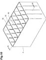
- FIG 10 is a perspective view showing one example of a battery case.
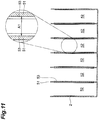
- FIG 11 is a sectional view taken on line XI-XI of FIG. 10 .
- the inside of the battery case 2 is divided into six compartments by five partition walls 51, and six cell chambers 52 are formed.
- Each cell chamber 52 is a space into which the electrode plate group 11 is inserted.
- Both side surfaces of the partition walls 51 and a pair of inner wall surfaces facing the partition walls 51 of the battery case 2 are provided with ribs 53 extending in the height direction of the battery case 2.
- the ribs 53 have a function of appropriately pressing (compressing) the electrode plate groups 11 that have been inserted into the cell chamber 52 in the stacking direction of the electrode plate group 11 (the stacking direction of the positive electrode plate 12 and the negative electrode plate 13 when the electrode plate group 11 is stored in the battery case 2).
- the ratio (D1/A1) of the thickness D1 of the electrode plate group to the inner dimension A1 is usually 0.85 or more.
- D1/A1 may be 0.90 or more or 0.96 or more.
- the upper limit of D1/A1 is not particularly limited, but may be, for example, 1.00. In other words, D1/A1 is, for example, 0.85 to 1.00, and may be 0.90 to 1.00 or 0.96 to 1.00.
- the lower limit of the inner dimension A1 may be, for example, 3.0 cm.
- the upper limit of the inner dimension A1 may be, for example, 5.0 cm.
- the present inventors suppose as follows. In other words, when S1/V1 is 8.9 cm -1 or more and p1/n1 is 1.35 or more, it is supposed that the density of electric current per electrode becomes small, and the inside resistance is reduced, whereby the charge acceptance is easily improved. As a result, SOC can be maintained in a high range, SOC shifts in a high range, whereby the negative electrode current-collecting portion 32 is not easily converted into lead sulfate, and therefore, thinning of the negative electrode current-collecting portion 32 does not easily occur. Thus, it is supposed that excellent ISS cycle characteristics are obtained. Furthermore, it is also supposed that a charging reaction easily proceeds, and therefore, lead sulfate generated in the negative electrode current-collecting portion 32 is easily reduced to metallic lead.
- a method for manufacturing a lead storage battery 1 in accordance with the present embodiment includes, for example: an electrode plate manufacturing step of obtaining electrode plates (a positive electrode plate 12 and a negative electrode plate 13); and an assembly step of assembling component members including the electrode plates to obtain the lead storage battery 1.
- a current collector for example, a current collector grid such as a cast grid body, and an expanded grid body
- an electrode material paste a positive electrode material paste and a negative electrode material paste
- the positive electrode material paste contains, for example, a raw material (lead powder or the like) of the positive electrode active material, and may further contain other additives.
- the negative electrode material paste contains, for example, raw material of the negative electrode active material (lead powder or the like), a resin (bisphenol-based resin or the like) having a sulfone group and/or a sulfonate group.
- the paste may further contain other additives.
- the positive electrode material paste can be obtained, for example, according to the following method. Firstly, the additives (short fiber for reinforcement or the like) and water are added to the raw material of the positive electrode active material. Next, dilute sulfuric acid is added thereto, and then the mixture is kneaded to obtain the positive electrode material paste. When the positive electrode material paste is prepared, red lead (Pb 3 O 4 ) may be used as the raw material of the positive electrode active material, from the viewpoint of enabling the formation time to be reduced.
- the positive current collector 21 is filed with the positive electrode material paste, and the resultant current collector is subjected to aging and drying to obtain an unformed positive electrode.
- the amount of the short fiber for reinforcement to be blended is preferably 0.005 to 0.3% by mass, and may be 0.05 to 0.3% by mass, based on the total mass of the raw material (lead powder or the like) of the positive electrode active material.
- atmosphere conditions of a temperature of 35 to 85 °C and a humidity of 50 to 98 RH% for 15 to 60 hours are preferable.
- drying conditions conditions of a temperature of 45 to 80 °C for 15 to 30 hours are preferable.
- the negative electrode material paste can be obtained, for example, according to the following method. Firstly, additives (resin having a sulfone group and/or a sulfonate group, short fiber for reinforcement, barium sulfate, or the like) are added to the raw material of the negative electrode active material, followed by dry mixing thereof to obtain a mixture. Then, sulfuric acid (dilute sulfuric acid or the like) and a solvent (water such as ion-exchanged water, an organic solvent, or the like) are added to the mixture, and the resultant mixture is kneaded, whereby the negative electrode material paste is obtained.
- additives resin having a sulfone group and/or a sulfonate group, short fiber for reinforcement, barium sulfate, or the like
- sulfuric acid dilute sulfuric acid or the like
- a solvent water such as ion-exchanged water, an organic solvent, or the like
- the negative electrode material paste is filled in the negative electrode current collector 31 (for example, a current collector grid such as a cast grid body or an expanded grid body) is filled with the obtained negative electrode paste, and the resultant current collector is subsequently subjected to aging and drying to obtain an unformed negative electrode plate.
- the negative electrode current collector 31 for example, a current collector grid such as a cast grid body or an expanded grid body
- the amount of each component to be blended is preferably in the following range.
- the amount of the resin having the sulfone group and/or the sulfonate group to be blended is preferably 0.01 to 2.0% by mass, and may be 0.05 to 1.0% by mass, 0.1 to 0.5% by mass, or 0.1 to 0.3% by mass in terms of the solid content of the resin, based on the total mass of the raw material (lead powder or the like) of the negative electrode active material.
- the amount of the carbonaceous material to be blended is preferably 0.1 to 3% by mass, and may be 0.2 to 1.4% by mass in terms of the solid content of the resin, based on the total mass of the raw material (lead powder or the like) of the negative electrode active material.
- the amount of the short fiber for reinforcement to be blended is preferably 0.05 to 0.15% by mass, based on the total mass of the raw material (lead powder or the like) of the negative electrode active material.
- the amount of barium sulfate to be blended is 0.01 to 2.0% by mass, and may be 0.01 to 1.0% by mass, based on the total mass of the raw material (lead powder or the like) of the negative electrode active material.
- atmosphere conditions of a temperature of 45 to 65 °C and a humidity of 70 to 98 RH% for 15 to 30 hours are preferable.
- drying conditions conditions of a temperature of 45 to 60 °C for 15 to 30 hours are preferable.
- the unformed negative electrode plate and the unformed positive electrode plate that have been produced as described above are alternately stacked with a separator disposed therebetween, and current-collecting portions of the electrode plates that have the same polarity are connected (welded or the like) to each other by a strap to obtain an electrode group.
- This electrode plate group is arranged in the battery case to produce an unformed battery.
- the electrolytic solution for example, dilute sulfuric acid
- the lead storage battery 1 is obtained.
- a lead storage battery having a predetermined specific gravity is usually obtained by allowing only an electric current to pass, but for the purpose of shortening the time for allowing an electric current to pass, electrolytic solution may be poured after dilute sulfuric acid is extracted following formation.
- the conditions of the formation and the specific gravity of the dilute sulfuric acid can be adjusted according to the properties of the electrode active material.
- the formation treatment is not limited to being carried out after the assembly step, but may be carried out after aging and drying in the electrode manufacturing process (tank formation).
- a plate-shaped lead-calcium-tin alloy (content of lead: 0.05% by mass, and content of calcium: 0.5% by mass) was provided with cut-openings, drawn such that the cut-openings were opened widely to prepare an expanded grid body.
- the positive electrode current collector had a width W2 of 145 mm, height H2 of 110 mm, and a thickness of 0.9 mm.
- the positive electrode material paste In producing the positive electrode material paste, in order to avoid a rapid temperature rise, dilute sulfuric acid was added in a stepwise manner. Subsequently, the produced positive electrode material paste was filled in the above-obtained positive electrode current collector, and was subjected to aging in an atmosphere at a temperature of 50 °C and humidity of 98% for 24 hours. Thus, an unformed positive electrode plate in which a positive electrode current collector was filled with unformed positive electrode material was obtained.
- the unformed positive electrode plate had a filled portion width W1 of 145 mm, a filled portion height H1 of 110 mm, and a thickness of 1.5 mm.
- a plate-shaped lead-calcium-tin alloy (content of lead: 0.05% by mass, and content of calcium: 0.5% by mass) was provided with cut-openings, drawn such that the cut-openings were opened widely to prepare an expanded grid body.
- the negative electrode current collector had a width W2 of 145 mm, height H2 of 110 mm, and a thickness of 0.8 mm.
- the produced negative electrode material paste was filled into the above-obtained negative electrode current collector, and the mixture was subjected to aging in an atmosphere at a temperature of 50 °C and humidity of 98% for 20 hours.
- an unformed negative electrode plate in which a negative electrode current collector was filled with unformed negative electrode material was obtained.
- the unformed negative electrode plate had a filled portion width W1 of 145 mm, a filled portion height H1 of 110 mm, and a thickness of 1.3 mm.
- a sheet-like article having a plurality of protruding ribs and a base portion supporting the ribs on one surface thereof was processed into a bag shape such that the surface having the ribs formed thereon faced the outside to prepare a separator (a bag-shaped separator) (see FIGs. 7 and 8 ).
- a separator a bag-shaped separator
- a total thickness was 0.8 mm
- a base portion thickness T was 0.2 mm
- a rib height H was 0.6 mm
- a width B of a rib upper base was 0.4 mm
- a width A of a rib lower base was 0.8 mm.
- An unformed negative electrode plate was accommodated in the obtained bag-shaped separator. Subsequently, seven unformed positive electrode plates and eight unformed negative electrode plates which were accommodated in the bag-shaped separator were alternately stacked, such that ribs on the separator were brought into contact with the unformed positive electrode plates. Next, a current-collecting portion on the unformed positive electrode plate and a current-collecting portion on the unformed negative electrode plate were cluster welded to the positive electrode-side strap and the negative electrode-side strap for each polarity to obtain an electrode plate group. The thickness D1 of the electrode plate group was 3.36 cm.
- a battery case having six cell chambers each having an inner dimension A1 of 3.5 cm was prepared, and electrode plate groups were each inserted into the six cell chambers of the battery case. Then, the electrode plate groups were inner-cell connected, and then a lid was thermally welded to the battery case. Thereafter, each liquid port plug was opened, and dilute sulfuric acid serving as an electrolytic solution was poured into each cell from each injection port provided in the lid. Then, an electric current of 25 A was allowed to flow at an ambient temperature of 40 °C for 20 hours, and the battery case was subjected to formation to produce an 85D23 battery (lead storage battery) defined in JIS D5301. The specific gravity of the electrolytic solution was adjusted to 1.28. The content of the positive electrode active material after formation (based on the total mass of the positive electrode material) was 99.9% by mass, and the content of the negative electrode active material after formation (based on the total mass of the negative electrode material) was 98.4% by mass.
- the total surface area S1 of the electrode material filled portion, the apparent total volume VI, the ratio (S1/V1) of total surface area S1 of the electrode material filled portion to the apparent total volume V1, the ratio (p1/n1) of the mass p1 of the positive electrode material to the mass n1 of the negative electrode material, the thickness D1 of the electrode plate group, the inner dimension A1 of the cell chamber, and the ratio (D1/A1) of the thickness D1 of the electrode plate group to the inner dimension A1 of cell chamber in the lead storage battery of Example 1 are shown in Table 1.
- a measurement sample of the specific surface area was prepared according to the following procedure. First, the formed battery was disassembled, the electrode plates (the positive electrode plates and the negative electrode plates) were taken out, washed with water, and then were dried at 50 °C for 24 hours. Next, 2 g of each of the electrode materials (the positive electrode material and the negative electrode material) was collected from the center portion of the above described electrode plates, and was dried at 130 °C for 30 minutes, whereby the measurement samples were produced.
- the measurement sample which was prepared in the above description was cooled with liquid nitrogen, the amount of adsorbed nitrogen gas was measured at a liquid nitrogen temperature according to a multipoint method, and the specific surface areas of the positive electrode material and the negative electrode material after the formation were calculated according to the BET method.
- the measurement conditions were as follows. As a result of having measured the measurement samples in this manner, the specific surface area of the positive electrode material was 6.3 m 2 /g and the specific surface area of the negative electrode material was 0.5 m 2 /g.
- HM-2201FS manufactured by Macsorb
- Deaeration time at 130 °C for 10 minutes
- Calculation of p1/n1 was performed as follows. Firstly, a positive electrode plate after formation was taken out from the battery case, washed with water for one hour, and then dried under an air atmosphere at 80 °C for 24 hours. The mass of the positive electrode plate was measured. Then, a positive electrode material was taken out from the positive electrode plate, and mass of a positive electrode current collector was calculated. The total mass of the positive electrode material was calculated from an amount obtained by removing the mass of the positive electrode current collector from the mass of the positive electrode plate. The total mass of a negative electrode material was calculated by the same procedure with respect to a negative electrode plate except that drying was carried out under a nitrogen atmosphere. From the total mass of the positive electrode material and the total mass of the negative electrode material per cell, p1/n1 was calculated, and p1/n1 was 1.35.
- a lead storage battery of Example 2 was produced in the same manner as in Example 1 except that an 85D26 battery (lead storage battery) specified in JIS D5301 instead of the 85D23 battery was produced (see Table 1).
- the inner dimension A1 in the 85D26 battery is 3.9 cm.
- the content of the positive electrode active material after formation (based on the total mass of the positive electrode material), the content of the negative electrode active material after formation, the specific surface area of the positive electrode material, and the specific surface area of the negative electrode material were same as those in Example 1.
- Lead storage batteries of Examples 3 to 13 and Comparative Examples 1 to 5 were produced, respectively, in the same manner as in Example 1 except that, in Examples 3 to 13 and Comparative Examples 1 to 5, filling amounts of a positive electrode material and a negative electrode material were adjusted, and the numbers of positive electrode plates and negative electrode plates to be used in electrode plate groups were changed, and thereby the total surface area S1 of the electrode material filled portion, the apparent total volume V1, the ratio (S1/V1) of the total surface area S1 of the electrode material filled portion to the apparent total volume VI, the ratio (p1/n1) of the mass p1 of the positive electrode material to the mass n1 of the negative electrode material, the thickness D1 of the electrode plate group, the inner dimension A1 of the cell chamber, and the ratio (D1/A1) of the thickness D1 of the electrode plate group to the inner dimension A1 of the cell chamber were adjusted to the values shown in Table 1.
- the content of the positive electrode active material after formation (based on the total mass of the positive electrode material), the content of the negative electrode active material after formation, the specific surface area of the positive electrode material, and the specific surface area of the negative electrode material were the same as those in Example 1.
- Example 3 to 5 seven positive electrode plates and eight negative electrode plates were used for one electrode plate group.
- Examples 6 to 9 eight positive electrode plates and eight negative electrode plates were used for one electrode plate group.
- Examples 10 to 13 eight positive electrode plates and nine negative electrode plates were used for one electrode plate group.
- Comparative Examples 1 and 2 five positive electrode plates and six negative electrode plates were used for one electrode plate group.
- Comparative Examples 3 and 4 six positive electrode plates and seven negative electrode plates were used for one electrode plate group.
- Comparative Example 5 seven positive electrode plates and eight negative electrode plates were used for one electrode plate group.
- Lead storage batteries of Examples 14 to 22 were produced, respectively, in the same manner as in Example 1 except that, lignin sulfonate (resin including a sulfone group and/or a sulfonate group (in Table 2, negative electrode organic additives)) and acetylene black (a carbonaceous material) in producing the unformed negative electrode plate, aluminum (A1) ion concentration in the electrolytic solution, as well as the specific gravity of the electrolytic solution were changed or adjusted as shown in Table 2.
- lignin sulfonate resin including a sulfone group and/or a sulfonate group (in Table 2, negative electrode organic additives)
- acetylene black a carbonaceous material
- Table 2 details of bisphenol-based resin, Ketjen black, and scaly graphite are as follows:
- a lead storage battery of Example 23 was produced in the same manner as in Example 1 except that non-woven fabric was provided on a surface of the separator such that the surface of the separator facing the negative electrode plate was comprised of a non-woven fabric, and that the height H of the rib of the separator was adjusted such that a thickness D1 of the electrode plate group was the same value as the thickness D1 of the electrode plate group in Example 1 (see Table 2).
- the non-woven fabric non-woven fabric made of glass fiber (manufactured by Japan Vilene Company, Ltd., thickness: 0.1 mm, mass per unit area: 40 g/m 2 ) was used.
- a lead storage battery of Example 24 was produced in the same manner as in Example 1 except that non-woven fabric was provided on a surface of the separator such that the surface of the separator facing the negative electrode plate was comprised of a non-woven fabric, and that the height H of the rib of the separator was adjusted such that a thickness D1 of the electrode plate group was the same value as the thickness D1 of the electrode plate group in Example 1 (see Table 3).
- non-woven fabric non-woven fabric made of glass fiber (manufactured by Japan Vilene Company, Ltd., thickness: 0.3 mm) was used.
- the produced lead storage batteries were discharged at a constant current of 10.4 A at 25 °C for 30 minutes, and were allowed to stand still for 12 hours. Thereafter, the lead storage battery was charged at a constant voltage of 14.0 V for 60 seconds under a limited electric current of 100 A, and an electric current value at 5 seconds from starting discharge was measured. By comparing the electric current values, the charge acceptance was evaluated. Note here that the charge acceptance was relatively evaluated based on the measurement result of Example 1 where the measurement result of Example 1 was defined as 100.
- a battery temperature of the produced lead storage batteries was adjusted to -15 °C, and constant-current discharge at 300 A was carried out at -15 °C, and the discharge duration time until the cell voltage became lower than 6.0 V was measured. By comparing the discharge duration times, the low-temperature high-rate discharge performance was evaluated. Note here that the low-temperature high-rate discharge performance was relatively evaluated based on the measurement result of Example 1 where the measurement result of Example 1 was defined as 100.
- the ambient temperature was adjusted so as to bring the battery temperature to 25 °C.
- Batteries were subjected to a cycle test.
- one cycle is defined as an operation of discharging at a constant current of 45 A for 59 seconds and 300 A for 1 second, and then charging at a constant current and constant voltage of 100 A and 14 V for 60 seconds. Every 3600 cycles, batteries were stood still for 40 hours, after which cycles started again.
- This test is a cycle test simulating the use of a lead storage battery in an ISS vehicle. In this cycle test, charging gradually becomes insufficient when full charging is not carried out, because the charging amount is low in relation to the discharging amount.
- the performance with respect to decrease of electrolytic solution was evaluated as follows. A battery temperature was adjusted to 60 °C, constant voltage charge was carried out for 42 days (1008 hours) at 14.4 V. A difference between the weight of the battery immediately before constant voltage was carried out when the battery temperature reached 60 °C and the weight of the battery immediately after the constant voltage charge for 42 days had been finished was defined as the amount of decreased electrolytic solution. By comparing this amount, the performance with respect to decrease of electrolytic solution was evaluated. Note here that the performance with respect to decrease of electrolytic solution was relatively evaluated based on the decreased electrolytic solution of Comparative Example 5 where the decreased electrolytic solution of Comparative Example 5 was defined as 100.
- 1... lead storage battery 2... battery case, 11... electrode plate group, 12... positive electrode plate, 13... negative electrode plate, 14... bag-shaped separator, 15... positive electrode-side strap, 16... negative electrode-side strap, 21... positive electrode current collector, 22... positive electrode current-collecting portion (positive electrode ear portion), 23... positive electrode material, 24... positive electrode material filled portion, 31... negative electrode current collector, 32... negative electrode current-collecting portion (negative electrode ear portion), 33... negative electrode material, 34... negative electrode material filled portion, 40... separator, 45... mechanically sealed portion, 52... cell chamber, 53... rib.
Landscapes
- Chemical & Material Sciences (AREA)
- Chemical Kinetics & Catalysis (AREA)
- Electrochemistry (AREA)
- General Chemical & Material Sciences (AREA)
- Engineering & Computer Science (AREA)
- Manufacturing & Machinery (AREA)
- Materials Engineering (AREA)
- Composite Materials (AREA)
- Battery Electrode And Active Subsutance (AREA)
- Secondary Cells (AREA)
- Cell Separators (AREA)
Claims (16)
- Bleiakkumulator (1), umfassend:ein Batteriegehäuse (2), das eine Zellenkammer (52) umfasst;eine Elektrodenplattengruppe (11), die in der Zellenkammer (52) bereitgestellt ist und einen Separator (14), eine positive Elektrodenplatte (12) und eine negative Elektrodenplatte (13) umfasst, wobei die positive Elektrodenplatte (12) und die negative Elektrodenplatte (13) abwechselnd mit dem Separator (14) dazwischen angeordnet gestapelt sind; undeine Elektrolytlösung, die in der Zellenkammer (52) untergebracht ist,wobeidie positive Elektrodenplatte (12) umfasst:einen mit positivem Elektrodenmaterial gefüllten Abschnitt (24), der aus einem positiven Elektrodenmaterial (23) besteht;einen Stromabnehmer (21) der positiven Elektrode, der den mit positivem Elektrodenmaterial gefüllten Abschnitt (24) trägt; undeinen Laschenabschnitt (22) der positiven Elektrode, der an einem oberen Umfangsabschnitt des Stromabnehmers bereitgestellt ist,die negative Elektrodenplatte (13) umfasst:einen mit negativem Elektrodenmaterial gefüllten Abschnitt (34), der aus einem negativen Elektrodenmaterial (33) besteht;einen Stromabnehmer (31) der negativen Elektrode, der den mit negativem Elektrodenmaterial gefüllten Abschnitt (34) trägt; undeinen Laschenabschnitt (32) der negativen Elektrode, der an einem oberen Umfangsabschnitt des Stromabnehmers bereitgestellt ist,p1/n1 1,35 oder mehr beträgt, wobei p1 eine Masse des positiven Elektrodenmaterials (23) darstellt und n1 eine Masse des negativen Elektrodenmaterials (33) darstellt, unddadurch gekennzeichnet, dassS1/V1 8,9 cm-1 oder mehr beträgt, wobei S1 eine Gesamtoberfläche des mit positivem Elektrodenmaterial gefüllten Abschnitts (24) und des mit negativem Elektrodenmaterial gefüllten Abschnitts (34) darstellt, und V1 ein scheinbares Gesamtvolumen des mit positivem Elektrodenmaterial gefüllten Abschnitts (24) und des mit negativem Elektrodenmaterial gefüllten Abschnitts (34) darstellt,wobei S1 dargestellt wird durch
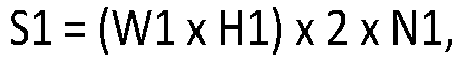 und V1 dargestellt wird durch
 wobei W1 eine Breite des mit Elektrodenmaterial gefüllten Abschnitts (24, 34) darstellt, H1 eine Höhe des mit Elektrodenmaterial gefüllten Abschnitts (24, 34) darstellt, N1 eine Anzahl der Elektrodenplatten (12, 13) in der Elektrodenplattengruppe (11) darstellt, und D1 eine Dicke der Elektrodenplattengruppe (11) darstellt.
 - Bleiakkumulator (1) nach Anspruch 1, wobei das negative Elektrodenmaterial (33) weiter ein Harz umfasst, das eine Sulfongruppe und/oder eine Sulfonatgruppe umfasst.
- Bleiakkumulator (1) nach Anspruch 2, wobei es sich bei dem Harz, das eine Sulfongruppe und/oder eine Sulfonatgruppe umfasst, um ein bisphenolbasiertes Harz handelt.
- Bleiakkumulator (1) nach Anspruch 3, wobei es sich bei dem bisphenolbasierten Harz um ein Kondensat aus Bisphenol, Aminobenzolsulfonsäure und Formaldehyd handelt.
- Bleiakkumulator (1) nach einem der Ansprüche 1 bis 4, wobei die Elektrolytlösung ein Aluminiumion umfasst.
- Bleiakkumulator (1) nach Anspruch 5, wobei eine Konzentration des Aluminiumions 0,02 bis 0,14 mol/L beträgt.
- Bleiakkumulator (1) nach einem der Ansprüche 1 bis 6, wobei das negative Elektrodenmaterial (33) weiter ein kohlenstoffhaltiges Material umfasst.
- Bleiakkumulator (1) nach Anspruch 7, wobei es sich bei dem kohlenstoffhaltigen Material um Ketjen Black oder Graphitschuppen handelt.
- Bleiakkumulator (1) nach einem der Ansprüche 1 bis 8, wobei die Elektrodenplattengruppe (11) ein Vlies zwischen der negativen Elektrodenplatte (13) und dem Separator (14) umfasst, und die negative Elektrodenplatte (13) und das Vlies miteinander in Berührung kommen.
- Bleiakkumulator (1) nach Anspruch 9, wobei das Vlies mindestens eine Faser umfasst, ausgewählt aus einer Gruppe bestehend aus einer Glasfaser, einer Polyolefinfaser und einer aus Pulpe hergestellten Faser.
- Bleiakkumulator (1) nach einem der Ansprüche 1 bis 10, wobei das positive Elektrodenmaterial (23) eine spezifische Oberfläche von 4 m2/g oder mehr aufweist.
- Bleiakkumulator (1) nach einem der Ansprüche 1 bis 11, wobei das negative Elektrodenmaterial (33) eine spezifische Oberfläche von 0,4 m2/g oder mehr aufweist.
- Bleiakkumulator (1) nach einem der Ansprüche 1 bis 12, wobei die Elektrolytlösung eine spezifische Dichte von 1,25 bis 1,29 aufweist.
- Bleiakkumulator (1) nach einem der Ansprüche 1 bis 13, wobei D1/A1 0,85 oder mehr beträgt, wobei D1 eine Dicke der Elektrodenplattengruppe (11) darstellt, und A1 eine Innenabmessung der Zellenkammer (52) in einer Stapelrichtung der Elektrodenplattengruppe (11) darstellt.
- Bleiakkumulator (1) nach einem der Ansprüche 1 bis 14, wobei
der Separator (14) eine Rippe (42, 43) und einen Basisabschnitt (41) umfasst, der die Rippe (42, 43) trägt,
der Basisabschnitt (41) eine Dicke von 0,3 mm oder weniger aufweist, und
die Rippe (42, 43) eine Höhe von 0,6 mm oder weniger aufweist. - Bleiakkumulator (1) nach einem der Ansprüche 1 bis 15, wobei das positive Elektrodenmaterial (23) ein positiv elektrodenaktives Material umfasst, das negative Elektrodenmaterial (33) ein negativ elektrodenaktives Material umfasst, ein Gehalt des positiv elektrodenaktiven Materials in Bezug auf eine Masse p1 des positiven Elektrodenmaterials (23) 95 Masse-% oder mehr beträgt, und ein Gehalt des negativ elektrodenaktiven Materials in Bezug auf eine Masse n1 des negativen Elektrodenmaterials (33) 93 Masse-% oder mehr beträgt.
Applications Claiming Priority (2)
| Application Number | Priority Date | Filing Date | Title |
|---|---|---|---|
| PCT/JP2015/084846 WO2017098665A1 (ja) | 2015-12-11 | 2015-12-11 | 鉛蓄電池 |
| PCT/JP2016/086436 WO2017099144A1 (ja) | 2015-12-11 | 2016-12-07 | 鉛蓄電池 |
Publications (3)
| Publication Number | Publication Date |
|---|---|
| EP3389131A4 EP3389131A4 (de) | 2018-10-17 |
| EP3389131A1 EP3389131A1 (de) | 2018-10-17 |
| EP3389131B1 true EP3389131B1 (de) | 2020-08-05 |
Family
ID=59013949
Family Applications (1)
| Application Number | Title | Priority Date | Filing Date |
|---|---|---|---|
| EP16873037.2A Active EP3389131B1 (de) | 2015-12-11 | 2016-12-07 | Bleiakkumulator |
Country Status (4)
| Country | Link |
|---|---|
| EP (1) | EP3389131B1 (de) |
| JP (2) | JP6354913B2 (de) |
| CN (1) | CN108370070B (de) |
| WO (2) | WO2017098665A1 (de) |
Families Citing this family (19)
| Publication number | Priority date | Publication date | Assignee | Title |
|---|---|---|---|---|
| US20160240857A1 (en) * | 2015-02-18 | 2016-08-18 | Gs Yuasa International Ltd. | Lead-acid battery |
| WO2017098666A1 (ja) * | 2015-12-11 | 2017-06-15 | 日立化成株式会社 | 鉛蓄電池 |
| JP6421895B2 (ja) * | 2016-06-08 | 2018-11-14 | 日立化成株式会社 | 鉛蓄電池 |
| JP7111099B2 (ja) * | 2017-07-24 | 2022-08-02 | 株式会社Gsユアサ | 鉛蓄電池 |
| JP6569823B1 (ja) * | 2017-10-16 | 2019-09-04 | 日立化成株式会社 | 鉛蓄電池、アイドリングストップ車及びマイクロハイブリッド車 |
| EP3680979A4 (de) * | 2017-10-31 | 2021-06-16 | GS Yuasa International Ltd. | Bleiakkumulator für start-stopp-system |
| WO2019087679A1 (ja) * | 2017-10-31 | 2019-05-09 | 株式会社Gsユアサ | 鉛蓄電池 |
| CN113196558A (zh) * | 2018-08-17 | 2021-07-30 | 达拉米克有限责任公司 | 改进的铅酸电池隔板、抗翘曲隔板、电池、系统及相关方法 |
| CN109305021B (zh) * | 2018-09-13 | 2021-09-21 | 安徽统凌科技新能源有限公司 | 一种便于安装的防腐汽车蓄电池外壳 |
| CN109546232B (zh) * | 2018-11-02 | 2021-11-05 | 小洋电源股份有限公司 | 一种固态矽胶牵引蓄电池 |
| CN114450837A (zh) * | 2019-09-27 | 2022-05-06 | 株式会社杰士汤浅国际 | 铅蓄电池 |
| CN114450824A (zh) * | 2019-09-27 | 2022-05-06 | 株式会社杰士汤浅国际 | 铅蓄电池用负极板和铅蓄电池 |
| JP7424037B2 (ja) * | 2019-12-20 | 2024-01-30 | 株式会社Gsユアサ | 鉛蓄電池 |
| JP7090395B2 (ja) * | 2020-01-08 | 2022-06-24 | 古河電池株式会社 | 液式鉛蓄電池 |
| WO2022004723A1 (ja) * | 2020-06-30 | 2022-01-06 | 昭和電工マテリアルズ株式会社 | 電池用セパレータ、蓄電池、組電池及び電動車 |
| JP7079821B2 (ja) * | 2020-07-22 | 2022-06-02 | 古河電池株式会社 | 液式鉛蓄電池 |
| WO2022113633A1 (ja) | 2020-11-27 | 2022-06-02 | 株式会社Gsユアサ | 鉛蓄電池 |
| JP2024044869A (ja) * | 2022-09-21 | 2024-04-02 | エナジーウィズ株式会社 | 鉛蓄電池 |
| WO2025053154A1 (ja) | 2023-09-08 | 2025-03-13 | 株式会社Gsユアサ | 液式鉛蓄電池 |
Family Cites Families (21)
| Publication number | Priority date | Publication date | Assignee | Title |
|---|---|---|---|---|
| JP5017746B2 (ja) * | 2001-04-18 | 2012-09-05 | パナソニック株式会社 | 制御弁式鉛蓄電池 |
| JP4515902B2 (ja) | 2004-12-27 | 2010-08-04 | 古河電池株式会社 | 鉛蓄電池 |
| EP2280443B1 (de) * | 2008-05-20 | 2014-03-12 | GS Yuasa International Ltd. | Bleiakkumulatorbatterie und verfahren zur herstellung der bleiakkumulatorbatterie |
| JP2011233390A (ja) * | 2010-04-28 | 2011-11-17 | Panasonic Corp | 制御弁式鉛蓄電池 |
| EP3288107B1 (de) * | 2010-05-10 | 2019-02-20 | Hitachi Chemical Company, Ltd. | Bleiakkumulator |
| US9683101B2 (en) * | 2010-09-22 | 2017-06-20 | Daramic, Llc | Batteries, separators, components, and compositions with heavy metal removal capability and related methods |
| CN103109412B (zh) * | 2010-09-29 | 2016-06-08 | 株式会社杰士汤浅国际 | 铅蓄电池及搭载有该铅蓄电池的怠速停止车辆 |
| US9735409B2 (en) * | 2011-05-13 | 2017-08-15 | Hitachi Chemical Company, Ltd. | Lead acid battery |
| CN103891037B (zh) * | 2011-10-18 | 2016-08-17 | 日立化成株式会社 | 铅蓄电池 |
| CN202996961U (zh) * | 2012-12-10 | 2013-06-12 | 江西新威动力能源科技有限公司 | 一种铅蓄电池 |
| JP6045329B2 (ja) * | 2012-12-21 | 2016-12-14 | パナソニック株式会社 | 鉛蓄電池 |
| CN104471781B (zh) * | 2012-12-21 | 2016-04-06 | 松下知识产权经营株式会社 | 铅蓄电池 |
| WO2014097516A1 (ja) * | 2012-12-21 | 2014-06-26 | パナソニック株式会社 | 鉛蓄電池 |
| JP2014157703A (ja) * | 2013-02-15 | 2014-08-28 | Panasonic Corp | 鉛蓄電池 |
| CN103199307B (zh) * | 2013-03-08 | 2015-10-14 | 超威电源有限公司 | 一种内化成铅酸电池工艺 |
| CN104681879B (zh) * | 2013-11-29 | 2020-07-10 | 株式会社杰士汤浅国际 | 铅蓄电池 |
| JP6202197B2 (ja) * | 2014-04-22 | 2017-09-27 | 日立化成株式会社 | ビスフェノール系樹脂、樹脂組成物、電極層、電極及び鉛蓄電池 |
| JP6318852B2 (ja) * | 2014-05-26 | 2018-05-09 | 日立化成株式会社 | 鉛蓄電池 |
| JP6515935B2 (ja) * | 2015-01-14 | 2019-05-22 | 日立化成株式会社 | 鉛蓄電池、マイクロハイブリッド車及びアイドリングストップシステム車 |
| JP6338020B2 (ja) * | 2015-06-18 | 2018-06-06 | 日立化成株式会社 | 鉛蓄電池 |
| WO2017098666A1 (ja) * | 2015-12-11 | 2017-06-15 | 日立化成株式会社 | 鉛蓄電池 |
-
2015
- 2015-12-11 WO PCT/JP2015/084846 patent/WO2017098665A1/ja not_active Ceased
-
2016
- 2016-12-07 JP JP2017555112A patent/JP6354913B2/ja active Active
- 2016-12-07 WO PCT/JP2016/086436 patent/WO2017099144A1/ja not_active Ceased
- 2016-12-07 EP EP16873037.2A patent/EP3389131B1/de active Active
- 2016-12-07 CN CN201680072124.8A patent/CN108370070B/zh active Active
-
2018
- 2018-06-14 JP JP2018113528A patent/JP2018139230A/ja active Pending
Non-Patent Citations (1)
| Title |
|---|
| None * |
Also Published As
| Publication number | Publication date |
|---|---|
| JP2018139230A (ja) | 2018-09-06 |
| WO2017099144A1 (ja) | 2017-06-15 |
| JPWO2017099144A1 (ja) | 2018-06-07 |
| EP3389131A4 (de) | 2018-10-17 |
| JP6354913B2 (ja) | 2018-07-11 |
| CN108370070A (zh) | 2018-08-03 |
| CN108370070B (zh) | 2021-10-01 |
| WO2017098665A1 (ja) | 2017-06-15 |
| EP3389131A1 (de) | 2018-10-17 |
Similar Documents
| Publication | Publication Date | Title |
|---|---|---|
| EP3389131B1 (de) | Bleiakkumulator | |
| EP3389130B1 (de) | Bleiakkumulator | |
| JP6743861B2 (ja) | 液式鉛蓄電池及びその製造方法 | |
| EP2709200B1 (de) | Bleibatterie | |
| EP3288107B1 (de) | Bleiakkumulator | |
| EP3419101B1 (de) | Bleiakkumulator, mikrohybridfahrzeug und fahrzeug mit start-stoppsystem | |
| EP3384543B1 (de) | Negative elektrode und elektrolytlösung für bleisäurebatterie, verfahren zur herstellung derselben, und bleisäurebatterie umfassend diese negative elektrode oder diese elektrolytlösung | |
| EP3422461A1 (de) | Blei-säure-akkumulator | |
| US10873108B2 (en) | Lithium battery | |
| EP3343671A1 (de) | Bleiakkumulatorseparator, bleiakkumulator und verfahren zur herstellung davon | |
| JP2017045539A (ja) | 鉛蓄電池 | |
| JP6781365B2 (ja) | 鉛蓄電池 | |
| JP6996274B2 (ja) | 鉛蓄電池 | |
| JP2020191312A (ja) | 鉛蓄電池 | |
| EP4576311A1 (de) | Bleiakkumulator | |
| JP7725224B2 (ja) | 電極群及び鉛蓄電池 | |
| JP6760347B2 (ja) | 鉛蓄電池 | |
| JPWO2019235216A1 (ja) | 鉛蓄電池 |
Legal Events
| Date | Code | Title | Description |
|---|---|---|---|
| STAA | Information on the status of an ep patent application or granted ep patent |
Free format text: STATUS: THE INTERNATIONAL PUBLICATION HAS BEEN MADE |
|
| PUAI | Public reference made under article 153(3) epc to a published international application that has entered the european phase |
Free format text: ORIGINAL CODE: 0009012 |
|
| STAA | Information on the status of an ep patent application or granted ep patent |
Free format text: STATUS: REQUEST FOR EXAMINATION WAS MADE |
|
| 17P | Request for examination filed |
Effective date: 20180608 |
|
| A4 | Supplementary search report drawn up and despatched |
Effective date: 20180830 |
|
| AK | Designated contracting states |
Kind code of ref document: A1 Designated state(s): AL AT BE BG CH CY CZ DE DK EE ES FI FR GB GR HR HU IE IS IT LI LT LU LV MC MK MT NL NO PL PT RO RS SE SI SK SM TR |
|
| AX | Request for extension of the european patent |
Extension state: BA ME |
|
| DAV | Request for validation of the european patent (deleted) | ||
| DAX | Request for extension of the european patent (deleted) | ||
| STAA | Information on the status of an ep patent application or granted ep patent |
Free format text: STATUS: EXAMINATION IS IN PROGRESS |
|
| 17Q | First examination report despatched |
Effective date: 20190423 |
|
| GRAP | Despatch of communication of intention to grant a patent |
Free format text: ORIGINAL CODE: EPIDOSNIGR1 |
|
| STAA | Information on the status of an ep patent application or granted ep patent |
Free format text: STATUS: GRANT OF PATENT IS INTENDED |
|
| RIC1 | Information provided on ipc code assigned before grant |
Ipc: H01M 10/12 20060101AFI20200122BHEP Ipc: H01M 4/68 20060101ALI20200122BHEP Ipc: H01M 2/18 20060101ALI20200122BHEP Ipc: H01M 10/08 20060101ALI20200122BHEP Ipc: H01M 10/06 20060101ALI20200122BHEP Ipc: H01M 4/73 20060101ALI20200122BHEP Ipc: H01M 4/66 20060101ALI20200122BHEP Ipc: H01M 2/16 20060101ALI20200122BHEP Ipc: H01M 4/02 20060101ALN20200122BHEP Ipc: H01M 4/62 20060101ALI20200122BHEP Ipc: H01M 4/14 20060101ALI20200122BHEP |
|
| INTG | Intention to grant announced |
Effective date: 20200226 |
|
| GRAJ | Information related to disapproval of communication of intention to grant by the applicant or resumption of examination proceedings by the epo deleted |
Free format text: ORIGINAL CODE: EPIDOSDIGR1 |
|
| STAA | Information on the status of an ep patent application or granted ep patent |
Free format text: STATUS: EXAMINATION IS IN PROGRESS |
|
| GRAR | Information related to intention to grant a patent recorded |
Free format text: ORIGINAL CODE: EPIDOSNIGR71 |
|
| GRAS | Grant fee paid |
Free format text: ORIGINAL CODE: EPIDOSNIGR3 |
|
| STAA | Information on the status of an ep patent application or granted ep patent |
Free format text: STATUS: GRANT OF PATENT IS INTENDED |
|
| GRAA | (expected) grant |
Free format text: ORIGINAL CODE: 0009210 |
|
| STAA | Information on the status of an ep patent application or granted ep patent |
Free format text: STATUS: THE PATENT HAS BEEN GRANTED |
|
| INTC | Intention to grant announced (deleted) | ||
| RIC1 | Information provided on ipc code assigned before grant |
Ipc: H01M 4/66 20060101ALI20200618BHEP Ipc: H01M 4/14 20060101ALI20200618BHEP Ipc: H01M 4/73 20060101ALI20200618BHEP Ipc: H01M 2/16 20060101ALI20200618BHEP Ipc: H01M 10/08 20060101ALI20200618BHEP Ipc: H01M 4/62 20060101ALI20200618BHEP Ipc: H01M 2/18 20060101ALI20200618BHEP Ipc: H01M 4/68 20060101ALI20200618BHEP Ipc: H01M 10/06 20060101ALI20200618BHEP Ipc: H01M 10/12 20060101AFI20200618BHEP Ipc: H01M 4/02 20060101ALN20200618BHEP |
|
| AK | Designated contracting states |
Kind code of ref document: B1 Designated state(s): AL AT BE BG CH CY CZ DE DK EE ES FI FR GB GR HR HU IE IS IT LI LT LU LV MC MK MT NL NO PL PT RO RS SE SI SK SM TR |
|
| INTG | Intention to grant announced |
Effective date: 20200629 |
|
| REG | Reference to a national code |
Ref country code: GB Ref legal event code: FG4D |
|
| REG | Reference to a national code |
Ref country code: CH Ref legal event code: EP |
|
| REG | Reference to a national code |
Ref country code: AT Ref legal event code: REF Ref document number: 1300008 Country of ref document: AT Kind code of ref document: T Effective date: 20200815 |
|
| REG | Reference to a national code |
Ref country code: DE Ref legal event code: R096 Ref document number: 602016041648 Country of ref document: DE |
|
| REG | Reference to a national code |
Ref country code: IE Ref legal event code: FG4D |
|
| REG | Reference to a national code |
Ref country code: LT Ref legal event code: MG4D |
|
| REG | Reference to a national code |
Ref country code: NL Ref legal event code: MP Effective date: 20200805 |
|
| REG | Reference to a national code |
Ref country code: AT Ref legal event code: MK05 Ref document number: 1300008 Country of ref document: AT Kind code of ref document: T Effective date: 20200805 |
|
| PG25 | Lapsed in a contracting state [announced via postgrant information from national office to epo] |
Ref country code: AT Free format text: LAPSE BECAUSE OF FAILURE TO SUBMIT A TRANSLATION OF THE DESCRIPTION OR TO PAY THE FEE WITHIN THE PRESCRIBED TIME-LIMIT Effective date: 20200805 Ref country code: SE Free format text: LAPSE BECAUSE OF FAILURE TO SUBMIT A TRANSLATION OF THE DESCRIPTION OR TO PAY THE FEE WITHIN THE PRESCRIBED TIME-LIMIT Effective date: 20200805 Ref country code: BG Free format text: LAPSE BECAUSE OF FAILURE TO SUBMIT A TRANSLATION OF THE DESCRIPTION OR TO PAY THE FEE WITHIN THE PRESCRIBED TIME-LIMIT Effective date: 20201105 Ref country code: ES Free format text: LAPSE BECAUSE OF FAILURE TO SUBMIT A TRANSLATION OF THE DESCRIPTION OR TO PAY THE FEE WITHIN THE PRESCRIBED TIME-LIMIT Effective date: 20200805 Ref country code: NO Free format text: LAPSE BECAUSE OF FAILURE TO SUBMIT A TRANSLATION OF THE DESCRIPTION OR TO PAY THE FEE WITHIN THE PRESCRIBED TIME-LIMIT Effective date: 20201105 Ref country code: GR Free format text: LAPSE BECAUSE OF FAILURE TO SUBMIT A TRANSLATION OF THE DESCRIPTION OR TO PAY THE FEE WITHIN THE PRESCRIBED TIME-LIMIT Effective date: 20201106 Ref country code: PT Free format text: LAPSE BECAUSE OF FAILURE TO SUBMIT A TRANSLATION OF THE DESCRIPTION OR TO PAY THE FEE WITHIN THE PRESCRIBED TIME-LIMIT Effective date: 20201207 Ref country code: LT Free format text: LAPSE BECAUSE OF FAILURE TO SUBMIT A TRANSLATION OF THE DESCRIPTION OR TO PAY THE FEE WITHIN THE PRESCRIBED TIME-LIMIT Effective date: 20200805 Ref country code: HR Free format text: LAPSE BECAUSE OF FAILURE TO SUBMIT A TRANSLATION OF THE DESCRIPTION OR TO PAY THE FEE WITHIN THE PRESCRIBED TIME-LIMIT Effective date: 20200805 Ref country code: FI Free format text: LAPSE BECAUSE OF FAILURE TO SUBMIT A TRANSLATION OF THE DESCRIPTION OR TO PAY THE FEE WITHIN THE PRESCRIBED TIME-LIMIT Effective date: 20200805 |
|
| PG25 | Lapsed in a contracting state [announced via postgrant information from national office to epo] |
Ref country code: IS Free format text: LAPSE BECAUSE OF FAILURE TO SUBMIT A TRANSLATION OF THE DESCRIPTION OR TO PAY THE FEE WITHIN THE PRESCRIBED TIME-LIMIT Effective date: 20201205 Ref country code: PL Free format text: LAPSE BECAUSE OF FAILURE TO SUBMIT A TRANSLATION OF THE DESCRIPTION OR TO PAY THE FEE WITHIN THE PRESCRIBED TIME-LIMIT Effective date: 20200805 Ref country code: LV Free format text: LAPSE BECAUSE OF FAILURE TO SUBMIT A TRANSLATION OF THE DESCRIPTION OR TO PAY THE FEE WITHIN THE PRESCRIBED TIME-LIMIT Effective date: 20200805 Ref country code: RS Free format text: LAPSE BECAUSE OF FAILURE TO SUBMIT A TRANSLATION OF THE DESCRIPTION OR TO PAY THE FEE WITHIN THE PRESCRIBED TIME-LIMIT Effective date: 20200805 Ref country code: NL Free format text: LAPSE BECAUSE OF FAILURE TO SUBMIT A TRANSLATION OF THE DESCRIPTION OR TO PAY THE FEE WITHIN THE PRESCRIBED TIME-LIMIT Effective date: 20200805 |
|
| PG25 | Lapsed in a contracting state [announced via postgrant information from national office to epo] |
Ref country code: DK Free format text: LAPSE BECAUSE OF FAILURE TO SUBMIT A TRANSLATION OF THE DESCRIPTION OR TO PAY THE FEE WITHIN THE PRESCRIBED TIME-LIMIT Effective date: 20200805 Ref country code: CZ Free format text: LAPSE BECAUSE OF FAILURE TO SUBMIT A TRANSLATION OF THE DESCRIPTION OR TO PAY THE FEE WITHIN THE PRESCRIBED TIME-LIMIT Effective date: 20200805 Ref country code: RO Free format text: LAPSE BECAUSE OF FAILURE TO SUBMIT A TRANSLATION OF THE DESCRIPTION OR TO PAY THE FEE WITHIN THE PRESCRIBED TIME-LIMIT Effective date: 20200805 Ref country code: SM Free format text: LAPSE BECAUSE OF FAILURE TO SUBMIT A TRANSLATION OF THE DESCRIPTION OR TO PAY THE FEE WITHIN THE PRESCRIBED TIME-LIMIT Effective date: 20200805 Ref country code: EE Free format text: LAPSE BECAUSE OF FAILURE TO SUBMIT A TRANSLATION OF THE DESCRIPTION OR TO PAY THE FEE WITHIN THE PRESCRIBED TIME-LIMIT Effective date: 20200805 |
|
| REG | Reference to a national code |
Ref country code: DE Ref legal event code: R097 Ref document number: 602016041648 Country of ref document: DE |
|
| PG25 | Lapsed in a contracting state [announced via postgrant information from national office to epo] |
Ref country code: AL Free format text: LAPSE BECAUSE OF FAILURE TO SUBMIT A TRANSLATION OF THE DESCRIPTION OR TO PAY THE FEE WITHIN THE PRESCRIBED TIME-LIMIT Effective date: 20200805 |
|
| PLBE | No opposition filed within time limit |
Free format text: ORIGINAL CODE: 0009261 |
|
| STAA | Information on the status of an ep patent application or granted ep patent |
Free format text: STATUS: NO OPPOSITION FILED WITHIN TIME LIMIT |
|
| PG25 | Lapsed in a contracting state [announced via postgrant information from national office to epo] |
Ref country code: SK Free format text: LAPSE BECAUSE OF FAILURE TO SUBMIT A TRANSLATION OF THE DESCRIPTION OR TO PAY THE FEE WITHIN THE PRESCRIBED TIME-LIMIT Effective date: 20200805 |
|
| 26N | No opposition filed |
Effective date: 20210507 |
|
| REG | Reference to a national code |
Ref country code: CH Ref legal event code: PL |
|
| GBPC | Gb: european patent ceased through non-payment of renewal fee |
Effective date: 20201207 |
|
| PG25 | Lapsed in a contracting state [announced via postgrant information from national office to epo] |
Ref country code: SI Free format text: LAPSE BECAUSE OF FAILURE TO SUBMIT A TRANSLATION OF THE DESCRIPTION OR TO PAY THE FEE WITHIN THE PRESCRIBED TIME-LIMIT Effective date: 20200805 Ref country code: MC Free format text: LAPSE BECAUSE OF FAILURE TO SUBMIT A TRANSLATION OF THE DESCRIPTION OR TO PAY THE FEE WITHIN THE PRESCRIBED TIME-LIMIT Effective date: 20200805 |
|
| REG | Reference to a national code |
Ref country code: BE Ref legal event code: MM Effective date: 20201231 |
|
| PG25 | Lapsed in a contracting state [announced via postgrant information from national office to epo] |
Ref country code: IE Free format text: LAPSE BECAUSE OF NON-PAYMENT OF DUE FEES Effective date: 20201207 Ref country code: LU Free format text: LAPSE BECAUSE OF NON-PAYMENT OF DUE FEES Effective date: 20201207 Ref country code: FR Free format text: LAPSE BECAUSE OF NON-PAYMENT OF DUE FEES Effective date: 20201231 |
|
| PG25 | Lapsed in a contracting state [announced via postgrant information from national office to epo] |
Ref country code: CH Free format text: LAPSE BECAUSE OF NON-PAYMENT OF DUE FEES Effective date: 20201231 Ref country code: GB Free format text: LAPSE BECAUSE OF NON-PAYMENT OF DUE FEES Effective date: 20201207 Ref country code: LI Free format text: LAPSE BECAUSE OF NON-PAYMENT OF DUE FEES Effective date: 20201231 |
|
| PGFP | Annual fee paid to national office [announced via postgrant information from national office to epo] |
Ref country code: DE Payment date: 20211102 Year of fee payment: 6 |
|
| PG25 | Lapsed in a contracting state [announced via postgrant information from national office to epo] |
Ref country code: IS Free format text: LAPSE BECAUSE OF FAILURE TO SUBMIT A TRANSLATION OF THE DESCRIPTION OR TO PAY THE FEE WITHIN THE PRESCRIBED TIME-LIMIT Effective date: 20201205 Ref country code: TR Free format text: LAPSE BECAUSE OF FAILURE TO SUBMIT A TRANSLATION OF THE DESCRIPTION OR TO PAY THE FEE WITHIN THE PRESCRIBED TIME-LIMIT Effective date: 20200805 Ref country code: MT Free format text: LAPSE BECAUSE OF FAILURE TO SUBMIT A TRANSLATION OF THE DESCRIPTION OR TO PAY THE FEE WITHIN THE PRESCRIBED TIME-LIMIT Effective date: 20200805 Ref country code: CY Free format text: LAPSE BECAUSE OF FAILURE TO SUBMIT A TRANSLATION OF THE DESCRIPTION OR TO PAY THE FEE WITHIN THE PRESCRIBED TIME-LIMIT Effective date: 20200805 |
|
| PG25 | Lapsed in a contracting state [announced via postgrant information from national office to epo] |
Ref country code: MK Free format text: LAPSE BECAUSE OF FAILURE TO SUBMIT A TRANSLATION OF THE DESCRIPTION OR TO PAY THE FEE WITHIN THE PRESCRIBED TIME-LIMIT Effective date: 20200805 |
|
| PG25 | Lapsed in a contracting state [announced via postgrant information from national office to epo] |
Ref country code: BE Free format text: LAPSE BECAUSE OF NON-PAYMENT OF DUE FEES Effective date: 20201231 |
|
| REG | Reference to a national code |
Ref country code: DE Ref legal event code: R119 Ref document number: 602016041648 Country of ref document: DE |
|
| PG25 | Lapsed in a contracting state [announced via postgrant information from national office to epo] |
Ref country code: DE Free format text: LAPSE BECAUSE OF NON-PAYMENT OF DUE FEES Effective date: 20230701 |
|
| PGFP | Annual fee paid to national office [announced via postgrant information from national office to epo] |
Ref country code: IT Payment date: 20231110 Year of fee payment: 8 |
|
| PG25 | Lapsed in a contracting state [announced via postgrant information from national office to epo] |
Ref country code: IT Free format text: LAPSE BECAUSE OF NON-PAYMENT OF DUE FEES Effective date: 20241207 |