EP3388329B1 - Ship handling device - Google Patents
Ship handling device Download PDFInfo
- Publication number
- EP3388329B1 EP3388329B1 EP16872644.6A EP16872644A EP3388329B1 EP 3388329 B1 EP3388329 B1 EP 3388329B1 EP 16872644 A EP16872644 A EP 16872644A EP 3388329 B1 EP3388329 B1 EP 3388329B1
- Authority
- EP
- European Patent Office
- Prior art keywords
- ship
- dynamic positioning
- positioning control
- orientation
- predetermined
- Prior art date
- Legal status (The legal status is an assumption and is not a legal conclusion. Google has not performed a legal analysis and makes no representation as to the accuracy of the status listed.)
- Active
Links
Images


Classifications
-
- G—PHYSICS
- G05—CONTROLLING; REGULATING
- G05D—SYSTEMS FOR CONTROLLING OR REGULATING NON-ELECTRIC VARIABLES
- G05D1/00—Control of position, course or altitude of land, water, air, or space vehicles, e.g. automatic pilot
- G05D1/02—Control of position or course in two dimensions
- G05D1/0206—Control of position or course in two dimensions specially adapted to water vehicles
- G05D1/0208—Control of position or course in two dimensions specially adapted to water vehicles dynamic anchoring
-
- B—PERFORMING OPERATIONS; TRANSPORTING
- B63—SHIPS OR OTHER WATERBORNE VESSELS; RELATED EQUIPMENT
- B63H—MARINE PROPULSION OR STEERING
- B63H25/00—Steering; Slowing-down otherwise than by use of propulsive elements; Dynamic anchoring, i.e. positioning vessels by means of main or auxiliary propulsive elements
- B63H25/02—Initiating means for steering, for slowing down, otherwise than by use of propulsive elements, or for dynamic anchoring
-
- B—PERFORMING OPERATIONS; TRANSPORTING
- B63—SHIPS OR OTHER WATERBORNE VESSELS; RELATED EQUIPMENT
- B63H—MARINE PROPULSION OR STEERING
- B63H25/00—Steering; Slowing-down otherwise than by use of propulsive elements; Dynamic anchoring, i.e. positioning vessels by means of main or auxiliary propulsive elements
- B63H25/42—Steering or dynamic anchoring by propulsive elements; Steering or dynamic anchoring by propellers used therefor only; Steering or dynamic anchoring by rudders carrying propellers
-
- B—PERFORMING OPERATIONS; TRANSPORTING
- B63—SHIPS OR OTHER WATERBORNE VESSELS; RELATED EQUIPMENT
- B63H—MARINE PROPULSION OR STEERING
- B63H25/00—Steering; Slowing-down otherwise than by use of propulsive elements; Dynamic anchoring, i.e. positioning vessels by means of main or auxiliary propulsive elements
- B63H25/02—Initiating means for steering, for slowing down, otherwise than by use of propulsive elements, or for dynamic anchoring
- B63H2025/026—Initiating means for steering, for slowing down, otherwise than by use of propulsive elements, or for dynamic anchoring using multi-axis control levers, or the like, e.g. joysticks, wherein at least one degree of freedom is employed for steering, slowing down, or dynamic anchoring
Definitions
- the present invention relates to a ship handling device for a ship, the ship handling device being capable of executing dynamic positioning control for balancing a thrust of the ship with an external force acting on the ship so that a position and an orientation of the ship are maintained at a target position and a target orientation, respectively.
- a dynamic positioning device described in Patent Literature 1 includes a position detecting means, an orientation detecting means, and an anemoscope for detecting a wind direction and a wind speed as an external force.
- the dynamic positioning device includes a proportional-integral-derivative (PID) controller and an addition processing means.
- PID controller works out a control force and a moment to be added to the ship for making a deviation of a detected position from a setting position and a deviation of a detected orientation from a setting orientation zero.
- the addition processing means adds, to the control force and the moment thus worked out, a wind pressure component estimated from the wind direction and the wind speed having been detected. Then, based on output from the addition processing means, the dynamic positioning device calculates control operation amounts for a bow thruster, a variable pitch propeller, and a rudder, and controls the bow thruster, the variable pitch propeller, and the rudder.
- PTL2 describes a dynamic positioning system which includes: a PI control part for calculating a control instruction value of a propulsion device based on the deviation of a target azimuth of a hull and an actual azimuth; a disturbance presumption part for presuming disturbance applied in a rotation direction of the hull; a correction instruction value generation part for generating a control instruction value of the propulsion device for canceling the disturbance calculated by the disturbance presumption part and outputting it as a correction instruction value; and a correction part for correcting the control instruction value from the PI control part by the correction instruction value from the correction instruction value generation part and outputting it
- the dynamic positioning device described in PTL 1 simply includes the integral (I) term in the PID control by the PID controller, this dynamic positioning device has a low operational response on the sea because the position is a second-order lag of the thrust. That is, the dynamic positioning device described in PTL 1 is likely to cause hunting, and thus cannot execute the dynamic positioning control efficiently and accurately.
- some aspects of the present invention have an object to provide a ship handling device capable of executing dynamic positioning control efficiently and accurately.
- a ship handling device for a ship includes: a driving force source; a propulsion device; a position calculating device configured to calculate a position of the ship; and an orientation calculating device configured to calculate an orientation of the ship, wherein the ship handling device is capable of executing dynamic positioning control for balancing a thrust of the ship with an external force acting on the ship, and while the dynamic positioning control is active, in a case where a distance deviation from a target position is greater than a predetermined value and a first condition that a state where a moving amount of the ship per unit time is equal to or less than a predetermined amount has continued for a predetermined period of time is satisfied, or in a case where an orientation deviation from a target orientation is greater than a predetermined value and a second condition that a state where a turning amount of the ship per unit time is equal to or less than a predetermined amount has continued for a predetermined period of time is satisfied, a thrust setting value resulting from the dynamic positioning control at the time of determination on the first
- the ship handling device further includes a joystick lever, wherein while a state where the joystick lever is not operated is maintained, in a case where a ship speed is equal to or lower than a predetermined ship speed, in a case where the reference value is equal to or lower than a threshold, in a case where a state where a distance deviation from the target position is equal to or less than a predetermined distance has continued for a predetermined period of time, or in a case where a state where an orientation deviation from the target orientation is equal to or less than a predetermined angle has continued for a predetermined period of time, the ship handling device executes the dynamic positioning control in which the driving force source is operated at a rotation speed equal to or lower than a preset upper limit.
- the ship handling device is preferably configured such that while a state where the joystick lever is not operated is maintained, in a case where a ship speed is higher than the predetermined ship speed, in a case where the reference value is greater than the threshold, in a case where a distance deviation from the target position is greater than the predetermined distance, or in a case where an orientation deviation from the target orientation is greater than the predetermined angle, the ship handling device continuously performs the dynamic positioning control in which the limitation on the rotation speed has been canceled, the limitation causing the rotation speed to be equal to or lower than the upper limit.
- the thrust setting value representing the thrust balanced with the external force is stored as the reference value. This makes it possible to cancel the external force acting on the ship, and to calculate a thrust setting value used to cause the ship to move closer to the target position.
- control it is possible to reduce overshoot and hunting, as compared with a configuration in which, each time one cycle of the control is completed, an external force is obtained by, e.g., calculation and the external force thus obtained is added to a thrust setting value that is to be outputted. Consequently, with the above control, it is possible to execute the dynamic positioning control efficiently and accurately.
- a ship handling device capable of executing dynamic positioning control efficiently and accurately.
- the ship can achieve quietness, comfortability, and the like while the ship is located at or near the target position and the target orientation and is in a calm state where no external force acts on the ship.
- the ship handling device With the ship handling device according to the aspect of the present invention, even in a case where output from the driving force source is reduced once, the limitation on the output can be canceled if the ship enters a state where an external force acts on the ship. Consequently, it is possible to impart, to the ship, both of quietness, comfortability, and the like while the ship is in a calm state and a good response while the ship is in a state where an external force acts on the ship.
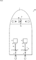
- the ship 100 illustrated in FIG. 1 is a so-called twin-screw ship (shaft ship).
- the number of propeller shafts and the type of the propulsion device are not limited to those in the twin-screw ship.
- the ship 100 may be a ship provided with a plurality of shafts, an outdrive-type ship, or a podded ship.
- a front-and-back direction and a left-and-right direction are defined with a bow direction of the ship 100 being defined as the front.
- the ship 100 is a shaft ship in which driving forces from engines 2, which are a driving force source, are transmitted to forward-backward propellers 4 through propeller shafts 4a.
- the ship 100 has a ship body 1 provided with a propulsion device 17 and the ship handling device 7.
- the propulsion device 17 includes the engines 2, switching clutches 3, the forward-backward propellers 4, rudders 5, a side thruster 6, and ECUs 16.
- the ship handling device 7 includes an accelerator lever 8, a steering wheel 9, a joystick lever 10, a side thruster controller 11, a monitor 12, a global positioning system (GPS) device 13, a heading sensor (orientation sensor) 14, and a ship handling control device 15.
- GPS global positioning system
- the ship 100 is the shaft ship including the propulsion device 17 disposed in a port side and a starboard side of the ship 100.
- the ship 100 is not limited to such a configuration.
- the ship 100 may be another type of ship such as a stern drive ship.
- the two engines 2 each generate a driving force for rotating a corresponding one of the forward-backward propellers 4 on the port side and the starboard side.
- One of the engines 2 is disposed in a rear portion of the port side of the ship body 1, and the other of the engines 2 is disposed in a rear portion of the starboard side of the ship body 1.
- the engines 2 each have an output shaft to which a corresponding one of the switching clutches 3 is connected.
- the two switching clutches 3 switch a rotation direction of the driving force, transmitted from the output shafts of the engines 2, between a forward direction and a reverse direction, and output the resulting driving force.
- the switching clutches 3 each have an input side connected to a corresponding one of the output shafts 2 of the engines 2.
- the switching clutches 3 each have an output side connected to a corresponding one of the propeller shafts 4a.
- the switching clutches 3 are each configured to transmit the driving force from a corresponding one of the engines 2 to a corresponding one of the propeller shafts 4a.
- the two forward-backward propellers 4 each generate a thrust in a front-and-rear direction.
- the forward-backward propellers 4 are respectively connected to the two propeller shafts 4a extending to the outside of the ship through a port-side portion and a starboard-side portion of the bottom of the ship body 1.
- the forward-backward propellers 4 are respectively rotated by the driving forces transmitted thereto from the engines 2 via the propeller shafts 4a.
- Multiple blades arranged around a rotating shaft of each of the propeller shafts 4a rotate in water in the periphery, so that a thrust is generated.
- the two rudders 5 change the direction of a water flow generated by rotation of the forward-backward propellers 4.
- One of the rudders 5 is disposed at a rear end (stern side) of the port-side portion of the bottom of the ship 1 and in rear of a corresponding one of the forward-backward propellers 4.
- the other of the rudders 5 is disposed at a rear end (stern side) of the starboard-side portion of the bottom of the ship body 1 and in rear of a corresponding one of the forward-backward propellers 4.
- the rudders 5 are each capable of turning about its corresponding rotating shaft provided in the ship body 1, within a predetermined angle range in a left-and-right direction.
- the rudders 5 are interlockingly connected to the steering wheel 9.
- the rudders 5 are configured such that, when the steering wheel 9 is operated to cause rear ends of the rudders 5 to be directed to the right of the ship body 1, a thrust generated by the resulting water flow presses the stern of the ship 100 to the left, so that the bow of the ship 100 is directed to the right.
- the rudders 5 are configured such that, when the steering wheel 9 is operated to cause the rear ends of the rudders 5 to be directed to the left of the ship body 1, a thrust generated by the resulting water flow presses the stern of the ship 100 to the right, so that the bow of the ship 100 is directed to the left.
- the side thruster 6 generates a thrust in the left-and-right direction.
- the side thruster 6 is disposed in a location closer to the bow of the ship body 1 and in the center in the left-and-right direction.
- the side thruster 6 includes a propeller 6a and a motor 6b.
- the motor 6b is connected to the side thruster controller 11, and is rotatable at a desired rotation speed.
- the side thruster 6 is configured such that a thrust generated by the propeller 6a acts in the left-and-right direction of the ship body 1.
- the side thruster 6 drives the motor 6b according to a signal from the side thruster controller 11 to rotate the propeller 6a so that a thrust having a desired magnitude and acting in the left-and-right direction is generated.
- the accelerator lever 8 included in the ship handling device 7 generates a signal for a rotation speed of the forward-backward propeller 4 on the port side, a signal for a rotation speed of the forward-backward propeller 4 on the starboard side, and signals for rotation directions of these forward-backward propellers 4.
- the accelerator lever 8 includes a lever for the forward-backward propeller 4 on the port side and a lever for the forward-backward propeller 4 on the starboard side. That is, the accelerator lever 8 is configured to independently generate a signal for the forward-backward propeller 4 on the port side and a signal for the forward-backward propeller 4 on the starboard side.
- the accelerator lever 8 is configured to be inclined at a desired angle in the front-and-rear direction of the ship 100.
- the accelerator lever 8 is configured to independently generate signals for rotation speeds of the engines 2 and signals for switching states of the switching clutches 3 corresponding to the engines 2, based on the direction and the amount of the operation.
- the accelerator lever 8 When the accelerator lever 8 is operated to be inclined forward, the accelerator lever 8 generates signals for the forward-backward propellers 4 to generate a thrust for moving the ship 100 forward. Meanwhile, when the accelerator lever 8 is operated to be inclined rearward, the accelerator lever 8 generates signals for the forward-backward propellers 4 to generate a thrust for moving the ship 100 backward.
- the steering wheel 9 included in the ship handling device 7 is used to change turning angles of the rudders 5.
- the steering wheel 9 is interlockingly connected to the rudders 5 on the port side and on the starboard side via a wire link mechanism or a hydraulic circuit.
- the rear ends of the rudders 5 are turned to be directed to the right. Consequently, a water flow generated by the forward-backward propellers 4 is directed to the right, so that the stern of the ship 100 is pressed to the left and accordingly the bow of the ship 100 is directed to the right.
- the rear ends of the rudders 5 are turned to be directed to the left. Consequently, a water flow generated by the forward-backward propellers 4 is directed to the left, so that the stern of the ship 100 is pressed to the right and accordingly the bow of the ship 100 is directed to the left.
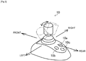
- the joystick lever 10 included in the ship handling device 7 generates a signal for causing the ship 100 to move in a desired direction.
- the joystick lever 10 is configured to be capable of being inclined in a desired direction at a desired angle.
- the joystick lever 10 can be operated to be turned about a lever shaft by a desired angle.
- the joystick lever 10 is configured to generate, based on the mode and the amount of the operation, signals for rotation speeds of the engines 2 and switching states of the switching clutches 3 and signals for a rotation speed and a rotation direction of the side thruster 6.
- the joystick lever 10 when the joystick lever 10 is operated to be inclined in a desired direction, the joystick lever 10 generates a signal for the forward-backward propellers 4 on both sides and a signal for the side thruster 6 to cause the ship 100 to move in a direction corresponding to the operation and with a thrust corresponding to the amount of the operation.
- the joystick lever 10 When the joystick lever 10 is operated to turn about the lever shaft, the joystick lever 10 generates a signal for the forward-backward propellers 4 on both sides and a signal for the side thruster 6 to cause the ship 100 to turn in a desired direction and with a thrust corresponding to the amount of the operation.
- the joystick lever 10 is provided with a positioning switch 10a for giving an instruction to start dynamic positioning control, a calibration switch 10b for causing the ship 100 to move laterally, to move obliquely, and to make a turn, and a change switch 10c for changing various settings.
- the dynamic positioning control refers to a control for causing the ship 100 to move toward a desired coordinate position, directing the bow of the ship 100 toward a desired orientation, and maintaining the ship 100 at that position.
- the side thruster controller 11 included in the ship handling device 7 is used to drive the side thruster 6.
- the side thruster controller 11 When the side thruster controller 11 is operated to be turned on, the side thruster controller 11 causes the motor 6b of the side thruster 6 to rotate in a desired direction so that the propeller 6a of the side thruster 6 generates a thrust in the left-and-right direction.
- the GPS device 13 included in the ship handling device 7 measures (calculates) positional coordinates of the ship 100.
- the GPS device 13 receives signals from a plurality of GPS satellites, calculates positional coordinates of the ship 100, and outputs a latitude La (n) and a longitude Lo (n) representing the current position. That is, as a position calculating device, the GPS device 13 calculates absolute values of the positional coordinates of the ship 100.
- the heading sensor 14 which is an orientation calculating device and is included in the ship handling device 7, measures (calculates) a direction of the ship 100.
- the heading sensor 14 calculates an orientation of the bow of the ship 100 from the Earth's magnetic field. That is, the heading sensor 14 calculates an absolute orientation of the bow of the ship 100.
- each of the ECUs 16 controls a corresponding one of the engines 2.
- various programs and data for controlling a corresponding one of the engines 2 are stored.
- the ECUs 16 are provided for their respective engines 2.
- Each of the ECUs 16 may have a configuration in which a CPU, a ROM, a RAM, an HDD and/or the like are connected to each other via a bus, or may have a configuration including a single-chip LSI and/or the like.
- Each of the ECUs 16 is connected to components of a corresponding one of the engines 2, such as a fuel adjustment valve of a fuel supply pump, a fuel injection valve, and various sensors (these components are not illustrated).
- the ECU 16 is capable of controlling an opening degree of the fuel adjustment valve and opening/closing of the fuel injection valve, and is also capable of obtaining information detected by various sensors.
- the ship handling control device 15 included in the ship handling device 7 controls the engines 2, the switching clutches 3, and the side thruster 6 based on detection signals from, e.g., the accelerator lever 8, the steering wheel 9, and the joystick lever 10.
- the ship handling control device 15 may be configured to be capable of implementing so-called automatic navigation that enables automatic handling of the ship along a route calculated from the current position and the preset destination based on the information from the GPS device 13.
- the ship handling control device 15 various programs and data for controlling the engines 2, the switching clutches 3, and the side thruster 6 are stored.
- the ship handling control device 15 may have a configuration in which a CPU, a ROM, a RAM, an HDD, and/or the like are connected to each other via a bus, or may have a configuration including a single-chip LSI and/or the like.
- the ship handling control device 15 is connected to the switching clutches 3 and the ECUs 16 of the engines 2, and can obtain information indicative of states of the switching clutches 3, information indicative of operation states of the engines 2, information indicative of rotation speeds that the ECUs 16 obtain from various sensors, and various signals that the ECUs 16 obtain from various sensors.
- the ship handling control device 15 can transmit, to the switching clutches 3, signals for changing (switching) clutch states.
- the ship handling control device 15 can transmit, to the ECUs 16, signals for controlling the fuel adjustment valves of the fuel supply pumps, the fuel injection valves, and other various devices of the engines 2.
- the ship handling control device 15 is connected to the accelerator lever 8 and the joystick lever 10, and can obtain signals from the acceleration lever 8 and the joystick lever 10.
- the ship handling control device 15 is connected to the side thruster controller 11 of the side thruster 6, and can transmit a signal for controlling the side thruster 6.
- the ship handling control device 15 is connected to the GPS device 13 and the heading sensor 14, and can obtain absolute coordinates and an absolute orientation of the ship 100.
- the ship handling control device 15 is connected to the monitor 12, and can cause the monitor 12 to display the current position of the ship 100 and a state of ship handling by the joystick lever 10.
- the ship handling device 7 that includes the ship handling control device 15 and executes the dynamic positioning control for maintaining the ship 100 at a target position and a target orientation on the sea.
- the ship handling control device 15 has the ROM, the RAM, and/or the like, as well as various arithmetic functions and a timer function.
- the ship handling control device 15 can calculate an external force acting on the ship 100 and a ship speed based on the position information from the GPS device 13 and the orientation information from the heading sensor 14. Then, the ship handling control device 15 further calculates a thrust setting value for achieving balance with the external force thus calculated, and controls the side thruster controller 11 and the ECUs 16 so that a thrust represented by the setting value is outputted.
- the ship handling control device 15 is connected to a dynamic positioning control switch 18.
- the ship handling control device 15 can recognize turning on/off of the dynamic positioning control switch 18.
- the dynamic positioning control switch 18 is disposed at a location in the ship body 1 where the dynamic positioning control switch 18 is operable by an operator.
- the dynamic positioning control switch 18 may be the positioning switch 10a provided in the joystick lever 10, or may be another one, e.g., the one displayed on the monitor 12 of touch panel type.
- the dynamic positioning control switch 18 starts the dynamic positioning control, whereas turning off the dynamic positioning control switch 18 cancels the dynamic positioning control.
- the dynamic positioning control has a silent mode. As will be described later, while the dynamic positioning control is active, if a predetermined condition for starting the silent mode is satisfied, a permission flag for the silent mode is set. Then, if a predetermined condition for the silent mode is satisfied, the dynamic positioning control in the silent mode is executed. If the predetermined condition is not satisfied while the dynamic positioning control in the silent mode is active, the silent mode is canceled and the normal dynamic positioning control is performed. Selection of whether to provide the silent mode in the dynamic positioning control can be made by a manufacturer in an initial setting. Specifically, as the ship handling device 7, it is possible to individually prepare a ship handling device 7 configured to be capable of executing the dynamic positioning control with the silent mode and a ship handling device 7 configured to execute the dynamic positioning control without the silent mode.
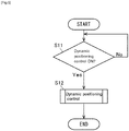
- step S11 it is determined whether or not an instruction to start the dynamic positioning control has been given.
- the dynamic positioning control is started when the dynamic positioning control switch 18 (see FIG. 4 ) is operated to be turned on. If the instruction to start the dynamic positioning control has been given, the process advances to step S12.
- the position and the orientation of the ship 100 on the sea at the time of turning-on of the dynamic positioning control switch 18 are set as a target position and a target orientation.
- step S12 the dynamic positioning control is executed.
- the side thruster controller 11 and the ECUs 16 are controlled so that a thrust given by the propulsion device 17 is balanced with an external force including a wind force and a tidal force.
- the ship 100 can be automatically maintained at a setting position and a setting orientation on the sea.
- the ship handling control device 15 may be connected to a switch for giving an instruction to turn on/off of the silent mode (described later).
- the switch for giving such an instruction may be the change switch 10c illustrated in FIG. 3 .
- an operation made by the dynamic positioning control switch 18 takes precedence over an instruction given by the silent mode switch. Specifically, if the dynamic positioning control switch 18 is turned on and the silent mode switch is turned on, the silent mode enters a stand-by state, in which the silent mode is to be started upon satisfaction of a predetermined condition. Meanwhile, even if the silent mode switch is turned on, the silent mode is not executed as long as the dynamic positioning control switch 18 is off.
- the silent mode switch may not be the change switch 10c, and may be another switch disposed in another position.
- the learning of the external force refers to storing, as a reference value, a thrust setting value representing a thrust balanced with a relatively large external force acting on the ship 100 and consequently stopping movement of the ship 100 at a position away from a target position.
- the ship handling device 7 efficiently learns the external force acting on the ship 100, and thus the ship handling device 7 can control the position and the orientation of the ship 100 efficiently and accurately.
- steps S122, S123, and S124 illustrated in FIG. 6 are parallel steps and thus the order of these steps may be changed.
- a position of the ship 100 is controlled by proportional-derivative (PD) control as in step S121.
- PD proportional-derivative
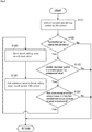
- step S122 it is determined in step S122 whether or not a predetermined period of time has been elapsed from the last learning (i.e., from a time point when the reference value was stored). If the result of the determination in step S122 is "Yes”, the process advances to step S123. Meanwhile, if the result of the determination in step S122 is "No", the process returns to step S121.
- step S123 it is determined whether or not a distance deviation from a target position having been set is greater than a predetermined value. In step S123, it is also determined whether or not an orientation deviation from a target orientation having been set is greater than a predetermined value. If the result of the determination in step S123 is "Yes”, the process advances to step S124. Meanwhile, if the result of the determination in step S123 is "No", the process returns to step S121.
- step S124 it is determined whether or not a state where a moving amount of the ship 100 per unit time is equal to or less than a predetermined amount has continued for a predetermined period of time. In step S124, it is also determined whether or not a state where a turning amount of the ship 100 per unit time is equal to or less than a predetermined amount has continued for a predetermined period of time. If the result of the determination in step S124 is "Yes”, the process advances to step S125. Meanwhile, if the result of the determination in step S124 is "No", the process returns to step S121.
- steps S123 and S124 it is determined whether or not, due to a thrust balancing with a large external force, the ship 100 has stopped moving at a position away from the target position before the ship 100 reaches the target position, and it is also determined whether or not, due to such a thrust, the ship 100 has stopped turning at an angle deviated from the target orientation before the ship 100 reaches the target orientation.
- step S125 a thrust setting value at the time of the determination in step S123 and the determination in step S124, i.e., a thrust setting value representing the thrust balanced with the external force is stored as a reference value.
- step S126 the reference value is added (vector added) to the thrust setting value resulting from the PD control.
- Steps S121 to S126 are performed sequentially in a repeated manner, and a new reference value is stored each time these steps are completed, i.e., the reference value is updated each time these steps are completed.
- the dynamic positioning control including the reference value thus added is executed by the PD control.
- the reference value is added to the feedback term of the PD control. This makes it possible to cancel the external force acting on the ship 100, and to calculate a thrust setting value used to cause the ship 100 to move closer to the target position.
- step S123 it is determined whether or not the external force and the thrust are balanced with each other, based on the determination of whether or not the deviation from the target position or the target orientation is greater than the threshold (step S123) and the determination of whether or not the state where the moving amount or the turning amount of the ship 100 per unit time is equal to or less than the predetermined amount has continued for the predetermined period of time (step S124).
- the subject of the leaning is set only to the amount of the control performed according to the distance deviation and the orientation deviation.
- the thrust setting value balanced with the external force is stored as the reference value. Thereafter, the dynamic positioning control is executed with use of the feedback term and the reference value that are vector added together. That is, according to the dynamic positioning control by the ship handling device 7, in a case where a relatively large external force acts on the ship, the external force is canceled by the reference value in the thrust setting value resulting from the PD control. In this manner, the dynamic positioning control by the ship handling device 7 creates a situation that is the same as a situation in which no external force acts on the ship, in terms of control. This enables the ship 100 to follow the target position and the target orientation efficiently and accurately.
- the dynamic positioning control by the ship handling device 7 has a control mode capable of automatically detecting stop of the movement of the ship 100 caused by a thrust balanced with an external force acting on the ship 100 and of canceling the external force acting on the ship 100. Consequently, as compared with a configuration in which, each time one cycle of the control is completed, an external force is obtained by, e.g., calculation and the external force thus obtained is added to a thrust setting value that is to be outputted, it is possible to reduce overshoot and hunting.
- step S123 since the dynamic positioning control by the ship handling device 7 has an interval before next learning as in step S123, it is possible to avoid hunting and divergence in operation of the ship 100 that may otherwise be caused by excessive learning.
- the silent mode refers to a mode in which an upper limit is set on the rotation speeds of the engines 2 so that the ship 100 archives quietness, comfortability, and the like.
- the engines 2 are each operated in a low idle rotation speed.
- the upper-limit rotation speed of each of the engines 2 is set at 550 rpm, for example.
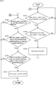
- step S131 it is determined, in a step prior to step S131, whether or not the silent mode has been canceled by turning-off operation by the silent mode switch. If the result of this determination is "Yes”, the process advances to step S131. Meanwhile, if the result of this determination is "No”, step S131 and its subsequent steps are not executed, but the normal dynamic positioning control is executed.
- step S131 it is determined whether or not a state where the joystick lever 10 is not operated is maintained. If the result of this determination is "Yes”, the process advances to step S132. Meanwhile, if the result of this determination is "No", step S131 is performed again. Assume here that the joystick lever 10 has not been operated since the instruction to start the dynamic positioning control was given (step S11 (see FIG. 5 )). Thus, the result of the determination in step S131 is "Yes".
- the dynamic positioning control is executed again. That is, at the time of completion of the operation by the joystick lever 10 (or after a predetermined period of time has elapsed after that time), the dynamic positioning control is automatically started again.
- step S132 it is determined whether or not a ship speed is equal to or lower than a silent-mode permitted ship speed.
- the silent-mode permitted ship speed is preset at a predetermined ship speed of the ship 100 that is obtained at an output lower than the minimum value of an output range of the engines 2 in which the silent mode is inexecutable. If the result of this determination is "Yes”, the process advances to step S133. Meanwhile, if the result of this determination is "No", the process returns to step S131.
- step S133 the permission flag for the execution of the silent mode is turned on. That is, if the two conditions of the above-described steps S131 and S132 are satisfied, the execution of the silent mode is permitted in the dynamic positioning control.
- step S134 it is determined whether or not a reference value is equal to or lower than a predetermined threshold. Specifically, in step S134, it is determined whether or not an external force acting on the ship 100 is small enough to allow execution of the silent mode. If the result of this determination is "Yes", the process advances to step S135.
- step S135 it is determined whether or not a state where a distance deviation from a target position is equal to or less than a silent-mode judgement distance has continued for a predetermined period of time. Specifically, in step S135, it is determined whether or not the position of the ship 100 relative to the target position is continuously within a range in which the silent mode is executable. If the result of this determination is "Yes", the process advances to step S136.
- step S136 it is determined whether or not a state where an orientation deviation from a target orientation is equal to or less than a silent-mode judgement angle has continued for a predetermined period of time. Specifically, in step S136, it is determined whether or not the orientation of the bow of the ship 100 relative to the target orientation continuously stays within an angle range in which the silent mode is executable. If the result of this determination is "Yes", the process advances to step S137.
- step S137 the dynamic positioning control in the silent mode is executed by the PD control. Specifically, in a state where the rotation speeds of the engines 2 are limited more severely than those of the normal dynamic positioning control, the position of the ship 100 is controlled toward the target position and the target orientation. Note that steps S134, S135, and S136 illustrated in FIG. 7 are parallel steps and thus the order of these steps may be changed.
- step S141 it is determined whether or not the joystick lever 10 has been operated. If the result of this determination is "Yes”, the process advances to step S147. Meanwhile, if the result of this determination is "No”, the process advances to step S142.
- step S142 it is determined whether or not a ship speed is higher than the silent-mode permitted ship speed. If the result of this determination is "Yes”, the process advances to step S146. Meanwhile, if the result of this determination is "No”, the process advances to step S143.
- step S143 it is determined whether or not a reference value is greater than the predetermined threshold. If the result of this determination is "Yes”, the process advances to step S146. Meanwhile, if the result of this determination is "No”, the process advances to step S144. That is, in step S143, it is determined whether or not an external force that is too large to execute the silent mode is acting on the ship 100.
- step S144 it is determined whether or not a distance deviation from a preset target position is greater than the silent-mode judgement distance. If the result of this determination is "Yes”, the process advances to step S146. Meanwhile, if the result of this determination is "No", the process advances to step S145.
- the silent-mode judgement distance is preset at an upper-limit distance deviation from the target position at which the silent mode can be continued. That is, in step S144, it is determined whether or not the ship 100 is largely away from the target position to an extent not allowing the silent mode to be continued.
- step S145 it is determined whether or not an orientation deviation from a preset target orientation is greater than the silent-mode judgement angle. If the result of this determination is "Yes”, the process advances to step S146. Meanwhile, if the result of this determination is "No", the process returns to step S141.
- the silent-mode judgement angle is preset at an upper-limit orientation deviation from the target orientation at which the silent mode can be continued. That is, in step S145, it is determined whether or not the bow of the ship 100 is largely inclined from the target orientation to an extent not allowing the silent mode to be continued.
- step S146 the silent mode is canceled. However, even after the silent mode is canceled, the silent mode can be executed again if the three conditions of steps S134, S135, and S136 illustrated in FIG. 7 are satisfied (see G in FIGs. 7 and 8 ).
- the present invention is applicable to ship handling devices.
Landscapes
- Engineering & Computer Science (AREA)
- Chemical & Material Sciences (AREA)
- Combustion & Propulsion (AREA)
- Mechanical Engineering (AREA)
- Ocean & Marine Engineering (AREA)
- Radar, Positioning & Navigation (AREA)
- Aviation & Aerospace Engineering (AREA)
- Remote Sensing (AREA)
- Physics & Mathematics (AREA)
- General Physics & Mathematics (AREA)
- Automation & Control Theory (AREA)
- Control Of Position, Course, Altitude, Or Attitude Of Moving Bodies (AREA)
- Control Of Vehicle Engines Or Engines For Specific Uses (AREA)
Applications Claiming Priority (2)
| Application Number | Priority Date | Filing Date | Title |
|---|---|---|---|
| JP2015242464A JP6421111B2 (ja) | 2015-12-11 | 2015-12-11 | 操船装置 |
| PCT/JP2016/068851 WO2017098744A1 (ja) | 2015-12-11 | 2016-06-24 | 操船装置 |
Publications (3)
| Publication Number | Publication Date |
|---|---|
| EP3388329A1 EP3388329A1 (en) | 2018-10-17 |
| EP3388329A4 EP3388329A4 (en) | 2018-11-21 |
| EP3388329B1 true EP3388329B1 (en) | 2019-11-06 |
Family
ID=59012968
Family Applications (1)
| Application Number | Title | Priority Date | Filing Date |
|---|---|---|---|
| EP16872644.6A Active EP3388329B1 (en) | 2015-12-11 | 2016-06-24 | Ship handling device |
Country Status (4)
| Country | Link |
|---|---|
| US (1) | US10782692B2 (ja) |
| EP (1) | EP3388329B1 (ja) |
| JP (1) | JP6421111B2 (ja) |
| WO (1) | WO2017098744A1 (ja) |
Families Citing this family (5)
| Publication number | Priority date | Publication date | Assignee | Title |
|---|---|---|---|---|
| US10730600B2 (en) * | 2018-07-26 | 2020-08-04 | Brunwick Corporation | Lanyard system and method for a marine vessel |
| DK181059B1 (en) * | 2018-11-16 | 2022-10-24 | Maersk Drilling As | Dynamic positioning control |
| CN111930108A (zh) * | 2020-02-25 | 2020-11-13 | 青岛海洋地质研究所 | 用于无人船的控制方法及控制装置、无人船 |
| JP2023159682A (ja) * | 2022-04-20 | 2023-11-01 | 日本発條株式会社 | 船舶、船舶制御装置、船舶制御方法およびプログラム |
| CN117622422A (zh) * | 2023-04-28 | 2024-03-01 | 中国船舶科学研究中心 | 用于船舶推进装置的监控系统及方法 |
Family Cites Families (19)
| Publication number | Priority date | Publication date | Assignee | Title |
|---|---|---|---|---|
| JPH01148696A (ja) | 1987-12-03 | 1989-06-12 | Hitachi Zosen Corp | 船舶の定点保持装置 |
| DE19625561A1 (de) * | 1996-06-26 | 1998-01-08 | Raytheon Anschuetz Gmbh | Verfahren zur Kursregelung von Wasserfahrzeugen über Grund |
| JP2001304909A (ja) * | 2000-04-26 | 2001-10-31 | Koden Electronics Co Ltd | 複合航法装置 |
| JP4261330B2 (ja) * | 2003-12-16 | 2009-04-30 | 古野電気株式会社 | 自動操舵制御装置および自動操舵装置 |
| JP4295645B2 (ja) * | 2004-03-11 | 2009-07-15 | 三井造船株式会社 | ウォータジェット推進船の自動定点保持装置 |
| JP4017630B2 (ja) * | 2004-12-28 | 2007-12-05 | ユニバーサル造船株式会社 | 船舶の船首方位制御設備 |
| JP2006194169A (ja) * | 2005-01-14 | 2006-07-27 | Mitsubishi Electric Corp | エンジン制御装置 |
| JP4709975B2 (ja) * | 2005-04-15 | 2011-06-29 | 三井造船株式会社 | 自動船位保持制御方法及び自動船位保持制御装置 |
| WO2006112416A1 (ja) * | 2005-04-15 | 2006-10-26 | Mitsui Engineering & Shipbuilding Co., Ltd. | 自動船位保持制御方法及び自動船位保持制御装置 |
| JP4706032B2 (ja) * | 2005-04-15 | 2011-06-22 | 三井造船株式会社 | 自動船位保持制御方法及び自動船位保持制御装置 |
| JP4968641B2 (ja) * | 2006-07-18 | 2012-07-04 | 三井造船株式会社 | 構造体の位置・方位制御方法、構造体の位置・方位制御システム及びプログラム |
| JP4791340B2 (ja) * | 2006-12-22 | 2011-10-12 | ヤマハ発動機株式会社 | 船舶用推進装置の制御装置、ならびにそれを用いた航走支援システムおよび船舶 |
| JP4809794B2 (ja) * | 2007-03-13 | 2011-11-09 | ヤンマー株式会社 | 操船装置 |
| JP5173745B2 (ja) * | 2008-10-30 | 2013-04-03 | 三菱重工業株式会社 | 定点保持制御装置およびその方法並びにプログラム |
| JP5443951B2 (ja) * | 2008-11-19 | 2014-03-19 | 古野電気株式会社 | 航海支援装置 |
| JP2010173589A (ja) * | 2009-01-30 | 2010-08-12 | Toyota Motor Corp | 船舶用位置保持制御装置 |
| JP5419622B2 (ja) * | 2009-10-01 | 2014-02-19 | 古野電気株式会社 | 船舶表示装置 |
| ATE544666T1 (de) * | 2009-12-14 | 2012-02-15 | Converteam Technology Ltd | Verfahren zur steuerung der position von vertäuten wasserfahrzeugen |
| JP2012185154A (ja) * | 2011-02-14 | 2012-09-27 | Dgs Computer:Kk | Gps信号による移動体制御装置、移動体制御方法、移動体制御プログラムおよびこれを用いた移動局管理システム、移動局管理方法、移動局管理プログラム |
-
2015
- 2015-12-11 JP JP2015242464A patent/JP6421111B2/ja active Active
-
2016
- 2016-06-24 EP EP16872644.6A patent/EP3388329B1/en active Active
- 2016-06-24 WO PCT/JP2016/068851 patent/WO2017098744A1/ja active Application Filing
- 2016-06-24 US US16/060,872 patent/US10782692B2/en active Active
Non-Patent Citations (1)
| Title |
|---|
| None * |
Also Published As
| Publication number | Publication date |
|---|---|
| US20190041857A1 (en) | 2019-02-07 |
| EP3388329A4 (en) | 2018-11-21 |
| JP2017105403A (ja) | 2017-06-15 |
| JP6421111B2 (ja) | 2018-11-07 |
| EP3388329A1 (en) | 2018-10-17 |
| US10782692B2 (en) | 2020-09-22 |
| WO2017098744A1 (ja) | 2017-06-15 |
Similar Documents
| Publication | Publication Date | Title |
|---|---|---|
| EP3388329B1 (en) | Ship handling device | |
| US10457371B2 (en) | Vessel steering apparatus | |
| US9193431B2 (en) | Ship steering device and ship steering method | |
| US10787238B2 (en) | Ship handling device | |
| US9771138B2 (en) | Boat maneuvering control method for boat and boat maneuvering control system for boat | |
| US7052341B2 (en) | Method and apparatus for controlling a propulsive force of a marine vessel | |
| JP2014076758A (ja) | 船舶の移動中心推定方法及びシステム | |
| JP2009067287A (ja) | 船舶 | |
| US20140174331A1 (en) | Ship maneuvering device | |
| US10078332B2 (en) | Ship handling device | |
| US9963214B2 (en) | Ship handling device | |
| EP3406516B1 (en) | Ship maneuvering device and ship provided therewith | |
| US10501161B2 (en) | Ship steering device and ship including the same | |
| EP3222511B1 (en) | A vessel operation control device | |
| JP2013014173A (ja) | 船舶操船装置 | |
| EP3434582A1 (en) | Ship | |
| US11453471B1 (en) | Vessel steering system and vessel steering method | |
| US11402838B1 (en) | System for and method of controlling watercraft | |
| US20240152146A1 (en) | Watercraft propulsion system, and watercraft including the watercraft propulsion system | |
| JP2022129788A (ja) | 船を制御するためのシステム及び方法 |
Legal Events
| Date | Code | Title | Description |
|---|---|---|---|
| STAA | Information on the status of an ep patent application or granted ep patent |
Free format text: STATUS: THE INTERNATIONAL PUBLICATION HAS BEEN MADE |
|
| PUAI | Public reference made under article 153(3) epc to a published international application that has entered the european phase |
Free format text: ORIGINAL CODE: 0009012 |
|
| STAA | Information on the status of an ep patent application or granted ep patent |
Free format text: STATUS: REQUEST FOR EXAMINATION WAS MADE |
|
| 17P | Request for examination filed |
Effective date: 20180711 |
|
| AK | Designated contracting states |
Kind code of ref document: A1 Designated state(s): AL AT BE BG CH CY CZ DE DK EE ES FI FR GB GR HR HU IE IS IT LI LT LU LV MC MK MT NL NO PL PT RO RS SE SI SK SM TR |
|
| AX | Request for extension of the european patent |
Extension state: BA ME |
|
| A4 | Supplementary search report drawn up and despatched |
Effective date: 20181023 |
|
| RIC1 | Information provided on ipc code assigned before grant |
Ipc: B63H 25/42 20060101AFI20181017BHEP Ipc: G05D 1/02 20060101ALI20181017BHEP |
|
| DAV | Request for validation of the european patent (deleted) | ||
| DAX | Request for extension of the european patent (deleted) | ||
| GRAP | Despatch of communication of intention to grant a patent |
Free format text: ORIGINAL CODE: EPIDOSNIGR1 |
|
| STAA | Information on the status of an ep patent application or granted ep patent |
Free format text: STATUS: GRANT OF PATENT IS INTENDED |
|
| INTG | Intention to grant announced |
Effective date: 20190531 |
|
| RIC1 | Information provided on ipc code assigned before grant |
Ipc: B63H 25/02 20060101ALI20190517BHEP Ipc: G05D 1/02 20060101ALI20190517BHEP Ipc: B63H 25/42 20060101AFI20190517BHEP |
|
| GRAS | Grant fee paid |
Free format text: ORIGINAL CODE: EPIDOSNIGR3 |
|
| GRAA | (expected) grant |
Free format text: ORIGINAL CODE: 0009210 |
|
| STAA | Information on the status of an ep patent application or granted ep patent |
Free format text: STATUS: THE PATENT HAS BEEN GRANTED |
|
| AK | Designated contracting states |
Kind code of ref document: B1 Designated state(s): AL AT BE BG CH CY CZ DE DK EE ES FI FR GB GR HR HU IE IS IT LI LT LU LV MC MK MT NL NO PL PT RO RS SE SI SK SM TR |
|
| REG | Reference to a national code |
Ref country code: GB Ref legal event code: FG4D |
|
| REG | Reference to a national code |
Ref country code: CH Ref legal event code: EP Ref country code: AT Ref legal event code: REF Ref document number: 1198409 Country of ref document: AT Kind code of ref document: T Effective date: 20191115 |
|
| REG | Reference to a national code |
Ref country code: IE Ref legal event code: FG4D |
|
| REG | Reference to a national code |
Ref country code: DE Ref legal event code: R096 Ref document number: 602016024083 Country of ref document: DE |
|
| REG | Reference to a national code |
Ref country code: NL Ref legal event code: FP |
|
| REG | Reference to a national code |
Ref country code: LT Ref legal event code: MG4D |
|
| PG25 | Lapsed in a contracting state [announced via postgrant information from national office to epo] |
Ref country code: PL Free format text: LAPSE BECAUSE OF FAILURE TO SUBMIT A TRANSLATION OF THE DESCRIPTION OR TO PAY THE FEE WITHIN THE PRESCRIBED TIME-LIMIT Effective date: 20191106 Ref country code: LT Free format text: LAPSE BECAUSE OF FAILURE TO SUBMIT A TRANSLATION OF THE DESCRIPTION OR TO PAY THE FEE WITHIN THE PRESCRIBED TIME-LIMIT Effective date: 20191106 Ref country code: SE Free format text: LAPSE BECAUSE OF FAILURE TO SUBMIT A TRANSLATION OF THE DESCRIPTION OR TO PAY THE FEE WITHIN THE PRESCRIBED TIME-LIMIT Effective date: 20191106 Ref country code: BG Free format text: LAPSE BECAUSE OF FAILURE TO SUBMIT A TRANSLATION OF THE DESCRIPTION OR TO PAY THE FEE WITHIN THE PRESCRIBED TIME-LIMIT Effective date: 20200206 Ref country code: FI Free format text: LAPSE BECAUSE OF FAILURE TO SUBMIT A TRANSLATION OF THE DESCRIPTION OR TO PAY THE FEE WITHIN THE PRESCRIBED TIME-LIMIT Effective date: 20191106 Ref country code: LV Free format text: LAPSE BECAUSE OF FAILURE TO SUBMIT A TRANSLATION OF THE DESCRIPTION OR TO PAY THE FEE WITHIN THE PRESCRIBED TIME-LIMIT Effective date: 20191106 Ref country code: PT Free format text: LAPSE BECAUSE OF FAILURE TO SUBMIT A TRANSLATION OF THE DESCRIPTION OR TO PAY THE FEE WITHIN THE PRESCRIBED TIME-LIMIT Effective date: 20200306 Ref country code: NO Free format text: LAPSE BECAUSE OF FAILURE TO SUBMIT A TRANSLATION OF THE DESCRIPTION OR TO PAY THE FEE WITHIN THE PRESCRIBED TIME-LIMIT Effective date: 20200206 Ref country code: GR Free format text: LAPSE BECAUSE OF FAILURE TO SUBMIT A TRANSLATION OF THE DESCRIPTION OR TO PAY THE FEE WITHIN THE PRESCRIBED TIME-LIMIT Effective date: 20200207 |
|
| PG25 | Lapsed in a contracting state [announced via postgrant information from national office to epo] |
Ref country code: HR Free format text: LAPSE BECAUSE OF FAILURE TO SUBMIT A TRANSLATION OF THE DESCRIPTION OR TO PAY THE FEE WITHIN THE PRESCRIBED TIME-LIMIT Effective date: 20191106 Ref country code: IS Free format text: LAPSE BECAUSE OF FAILURE TO SUBMIT A TRANSLATION OF THE DESCRIPTION OR TO PAY THE FEE WITHIN THE PRESCRIBED TIME-LIMIT Effective date: 20200306 Ref country code: RS Free format text: LAPSE BECAUSE OF FAILURE TO SUBMIT A TRANSLATION OF THE DESCRIPTION OR TO PAY THE FEE WITHIN THE PRESCRIBED TIME-LIMIT Effective date: 20191106 |
|
| PG25 | Lapsed in a contracting state [announced via postgrant information from national office to epo] |
Ref country code: AL Free format text: LAPSE BECAUSE OF FAILURE TO SUBMIT A TRANSLATION OF THE DESCRIPTION OR TO PAY THE FEE WITHIN THE PRESCRIBED TIME-LIMIT Effective date: 20191106 |
|
| PG25 | Lapsed in a contracting state [announced via postgrant information from national office to epo] |
Ref country code: EE Free format text: LAPSE BECAUSE OF FAILURE TO SUBMIT A TRANSLATION OF THE DESCRIPTION OR TO PAY THE FEE WITHIN THE PRESCRIBED TIME-LIMIT Effective date: 20191106 Ref country code: RO Free format text: LAPSE BECAUSE OF FAILURE TO SUBMIT A TRANSLATION OF THE DESCRIPTION OR TO PAY THE FEE WITHIN THE PRESCRIBED TIME-LIMIT Effective date: 20191106 Ref country code: ES Free format text: LAPSE BECAUSE OF FAILURE TO SUBMIT A TRANSLATION OF THE DESCRIPTION OR TO PAY THE FEE WITHIN THE PRESCRIBED TIME-LIMIT Effective date: 20191106 Ref country code: CZ Free format text: LAPSE BECAUSE OF FAILURE TO SUBMIT A TRANSLATION OF THE DESCRIPTION OR TO PAY THE FEE WITHIN THE PRESCRIBED TIME-LIMIT Effective date: 20191106 Ref country code: DK Free format text: LAPSE BECAUSE OF FAILURE TO SUBMIT A TRANSLATION OF THE DESCRIPTION OR TO PAY THE FEE WITHIN THE PRESCRIBED TIME-LIMIT Effective date: 20191106 |
|
| REG | Reference to a national code |
Ref country code: DE Ref legal event code: R097 Ref document number: 602016024083 Country of ref document: DE |
|
| REG | Reference to a national code |
Ref country code: AT Ref legal event code: MK05 Ref document number: 1198409 Country of ref document: AT Kind code of ref document: T Effective date: 20191106 |
|
| PG25 | Lapsed in a contracting state [announced via postgrant information from national office to epo] |
Ref country code: SK Free format text: LAPSE BECAUSE OF FAILURE TO SUBMIT A TRANSLATION OF THE DESCRIPTION OR TO PAY THE FEE WITHIN THE PRESCRIBED TIME-LIMIT Effective date: 20191106 Ref country code: SM Free format text: LAPSE BECAUSE OF FAILURE TO SUBMIT A TRANSLATION OF THE DESCRIPTION OR TO PAY THE FEE WITHIN THE PRESCRIBED TIME-LIMIT Effective date: 20191106 |
|
| PLBE | No opposition filed within time limit |
Free format text: ORIGINAL CODE: 0009261 |
|
| STAA | Information on the status of an ep patent application or granted ep patent |
Free format text: STATUS: NO OPPOSITION FILED WITHIN TIME LIMIT |
|
| 26N | No opposition filed |
Effective date: 20200807 |
|
| PG25 | Lapsed in a contracting state [announced via postgrant information from national office to epo] |
Ref country code: SI Free format text: LAPSE BECAUSE OF FAILURE TO SUBMIT A TRANSLATION OF THE DESCRIPTION OR TO PAY THE FEE WITHIN THE PRESCRIBED TIME-LIMIT Effective date: 20191106 Ref country code: AT Free format text: LAPSE BECAUSE OF FAILURE TO SUBMIT A TRANSLATION OF THE DESCRIPTION OR TO PAY THE FEE WITHIN THE PRESCRIBED TIME-LIMIT Effective date: 20191106 |
|
| REG | Reference to a national code |
Ref country code: NL Ref legal event code: HC Owner name: YANMAR POWER TECHNOLOGY CO, LTD.; JP Free format text: DETAILS ASSIGNMENT: CHANGE OF OWNER(S), CHANGE OF OWNER(S) NAME; FORMER OWNER NAME: YANMAR CO., LTD. Effective date: 20201126 |
|
| REG | Reference to a national code |
Ref country code: DE Ref legal event code: R119 Ref document number: 602016024083 Country of ref document: DE |
|
| PG25 | Lapsed in a contracting state [announced via postgrant information from national office to epo] |
Ref country code: MC Free format text: LAPSE BECAUSE OF FAILURE TO SUBMIT A TRANSLATION OF THE DESCRIPTION OR TO PAY THE FEE WITHIN THE PRESCRIBED TIME-LIMIT Effective date: 20191106 |
|
| REG | Reference to a national code |
Ref country code: CH Ref legal event code: PL |
|
| PG25 | Lapsed in a contracting state [announced via postgrant information from national office to epo] |
Ref country code: LU Free format text: LAPSE BECAUSE OF NON-PAYMENT OF DUE FEES Effective date: 20200624 |
|
| REG | Reference to a national code |
Ref country code: BE Ref legal event code: MM Effective date: 20200630 |
|
| PG25 | Lapsed in a contracting state [announced via postgrant information from national office to epo] |
Ref country code: IE Free format text: LAPSE BECAUSE OF NON-PAYMENT OF DUE FEES Effective date: 20200624 Ref country code: LI Free format text: LAPSE BECAUSE OF NON-PAYMENT OF DUE FEES Effective date: 20200630 Ref country code: CH Free format text: LAPSE BECAUSE OF NON-PAYMENT OF DUE FEES Effective date: 20200630 |
|
| PG25 | Lapsed in a contracting state [announced via postgrant information from national office to epo] |
Ref country code: BE Free format text: LAPSE BECAUSE OF NON-PAYMENT OF DUE FEES Effective date: 20200630 Ref country code: DE Free format text: LAPSE BECAUSE OF NON-PAYMENT OF DUE FEES Effective date: 20210101 |
|
| PG25 | Lapsed in a contracting state [announced via postgrant information from national office to epo] |
Ref country code: TR Free format text: LAPSE BECAUSE OF FAILURE TO SUBMIT A TRANSLATION OF THE DESCRIPTION OR TO PAY THE FEE WITHIN THE PRESCRIBED TIME-LIMIT Effective date: 20191106 Ref country code: MT Free format text: LAPSE BECAUSE OF FAILURE TO SUBMIT A TRANSLATION OF THE DESCRIPTION OR TO PAY THE FEE WITHIN THE PRESCRIBED TIME-LIMIT Effective date: 20191106 Ref country code: CY Free format text: LAPSE BECAUSE OF FAILURE TO SUBMIT A TRANSLATION OF THE DESCRIPTION OR TO PAY THE FEE WITHIN THE PRESCRIBED TIME-LIMIT Effective date: 20191106 |
|
| PG25 | Lapsed in a contracting state [announced via postgrant information from national office to epo] |
Ref country code: MK Free format text: LAPSE BECAUSE OF FAILURE TO SUBMIT A TRANSLATION OF THE DESCRIPTION OR TO PAY THE FEE WITHIN THE PRESCRIBED TIME-LIMIT Effective date: 20191106 |
|
| PGFP | Annual fee paid to national office [announced via postgrant information from national office to epo] |
Ref country code: NL Payment date: 20230620 Year of fee payment: 8 Ref country code: FR Payment date: 20230630 Year of fee payment: 8 |
|
| PGFP | Annual fee paid to national office [announced via postgrant information from national office to epo] |
Ref country code: IT Payment date: 20230623 Year of fee payment: 8 Ref country code: GB Payment date: 20230622 Year of fee payment: 8 |