EP3387188B1 - Pavé réalisé en forme de croix - Google Patents
Pavé réalisé en forme de croix Download PDFInfo
- Publication number
- EP3387188B1 EP3387188B1 EP16845324.9A EP16845324A EP3387188B1 EP 3387188 B1 EP3387188 B1 EP 3387188B1 EP 16845324 A EP16845324 A EP 16845324A EP 3387188 B1 EP3387188 B1 EP 3387188B1
- Authority
- EP
- European Patent Office
- Prior art keywords
- stone
- projecting
- sections
- paving
- composite
- Prior art date
- Legal status (The legal status is an assumption and is not a legal conclusion. Google has not performed a legal analysis and makes no representation as to the accuracy of the status listed.)
- Not-in-force
Links
Images


Classifications
-
- E—FIXED CONSTRUCTIONS
- E01—CONSTRUCTION OF ROADS, RAILWAYS, OR BRIDGES
- E01C—CONSTRUCTION OF, OR SURFACES FOR, ROADS, SPORTS GROUNDS, OR THE LIKE; MACHINES OR AUXILIARY TOOLS FOR CONSTRUCTION OR REPAIR
- E01C5/00—Pavings made of prefabricated single units
-
- E—FIXED CONSTRUCTIONS
- E01—CONSTRUCTION OF ROADS, RAILWAYS, OR BRIDGES
- E01C—CONSTRUCTION OF, OR SURFACES FOR, ROADS, SPORTS GROUNDS, OR THE LIKE; MACHINES OR AUXILIARY TOOLS FOR CONSTRUCTION OR REPAIR
- E01C5/00—Pavings made of prefabricated single units
- E01C5/06—Pavings made of prefabricated single units made of units with cement or like binders
-
- E—FIXED CONSTRUCTIONS
- E01—CONSTRUCTION OF ROADS, RAILWAYS, OR BRIDGES
- E01C—CONSTRUCTION OF, OR SURFACES FOR, ROADS, SPORTS GROUNDS, OR THE LIKE; MACHINES OR AUXILIARY TOOLS FOR CONSTRUCTION OR REPAIR
- E01C2201/00—Paving elements
- E01C2201/02—Paving elements having fixed spacing features
-
- E—FIXED CONSTRUCTIONS
- E01—CONSTRUCTION OF ROADS, RAILWAYS, OR BRIDGES
- E01C—CONSTRUCTION OF, OR SURFACES FOR, ROADS, SPORTS GROUNDS, OR THE LIKE; MACHINES OR AUXILIARY TOOLS FOR CONSTRUCTION OR REPAIR
- E01C2201/00—Paving elements
- E01C2201/06—Sets of paving elements
-
- E—FIXED CONSTRUCTIONS
- E01—CONSTRUCTION OF ROADS, RAILWAYS, OR BRIDGES
- E01C—CONSTRUCTION OF, OR SURFACES FOR, ROADS, SPORTS GROUNDS, OR THE LIKE; MACHINES OR AUXILIARY TOOLS FOR CONSTRUCTION OR REPAIR
- E01C2201/00—Paving elements
- E01C2201/16—Elements joined together
-
- E—FIXED CONSTRUCTIONS
- E01—CONSTRUCTION OF ROADS, RAILWAYS, OR BRIDGES
- E01C—CONSTRUCTION OF, OR SURFACES FOR, ROADS, SPORTS GROUNDS, OR THE LIKE; MACHINES OR AUXILIARY TOOLS FOR CONSTRUCTION OR REPAIR
- E01C2201/00—Paving elements
- E01C2201/16—Elements joined together
- E01C2201/162—Elements joined together with breaking lines
Definitions
- the present invention relates to a cross-shaped paving stone with two opposite projecting stone sections with mutually perpendicular, each two side surfaces and a front surface comprising vertical boundary surfaces.
- Such paving stones are well known. They have a walkable or passable top and an opposite bottom and a plurality of vertically arranged side surfaces and front surfaces. Through the cross shape can be made of such paving stones plaster bandages that have no continuous joints and thus have a good gearing effect. In particular, such paving stones are therefore suitable for heavy duty paving.
- a so-called heavy duty pavement is often desired, which gives the impression of high load-bearing capacity even on the outside.
- larger Stone thicknesses as well as special stone floor plans play a decisive role.
- TRILOC plaster in which the individual paving stones have an approximately triangular plan, and the so-called UNI Optiloc plaster, come in the angular paving stones are used.
- From the DE 102 05 135 A1 is a cross-shaped paving stone with two opposite projecting stone sections with mutually perpendicular, each having two side surfaces and a front surface comprehensive, vertical boundary surfaces known.
- this known paving stone projecting composite sections are arranged on all side surfaces and front surfaces of the protruding stone sections, but the composite sections of two opposing projecting stone sections are not arranged in an identical position.
- the GB 2 306 524 A describes a cross-shaped paving stone with two opposite projecting stone sections. On the side surfaces of two opposing protruding stone sections are arranged in an identical position, a protruding composite portion and a recessed composite portion.
- the FR 2 358 510 A1 describes a cross-shaped paving stone with two oppositely arranged projecting stone sections, wherein also here on the side surfaces of two opposing projecting stone sections in an identical position a projecting and a recessed composite section are arranged.
- the present invention has for its object to provide a paving stone of the type described above, with a particularly well-toothed plaster bandage can be reached.
- a protruding first composite portion is arranged at the towards the throat formed with the adjacent protruding stone portion at least one just as long, from a composite portion free side surface portion connects, and that are on other side surfaces and / or front surfaces projecting second composite sections, in cooperation with second composite sections of a neighboring stone for the production of a plaster bandage displacement of a first composite portion of the neighboring stone perpendicular to the corresponding side surface in the Allow final composite position with the first composite portion of the paving stone.
- the paving stone according to the invention which is particularly suitable for a heavy duty pavement and can absorb high loads, is cross-shaped in plan view and provided on its side surfaces and front surfaces with a special system of strip-shaped, vertically extending composite sections.
- the paving stone formed according to the invention therefore has a double composite system, which is formed on the one hand by the cross shape and on the other hand by the special composite sections. It is understood that already by the cross shape, a corresponding toothing effect is achieved and that the provided composite sections provide an additional toothing effect.
- a particularly well-toothed plaster bandage can thus be produced.
- several paving stones can be pushed together on a production board so that the composite sections of adjacent stones engage each other and the stones can be clipped accordingly.
- the special arrangement of the composite sections ensures that the stones must be placed in a special way and can not be separated easily by simple movement processes again.
- a special zigzag-shaped movement is required for assembling or juxtaposing and separating the stones, which is composed, for example, of two movement processes in the x-direction (horizontal in the drawing) and an intermediate movement in the y-direction (vertically in the drawing).
- the plaster formed is well secured by the circulating composite system of cross-shaped stones in the x and y direction against train.
- the bricks on the production board can not easily be pushed together, since the composite system engages after being pushed together in the first direction (x-direction) and thereby no longer permits a collapse in the second direction (y-direction).
- first composite sections are arranged in an identical position on the side surfaces of two opposite projecting stone sections are arranged.
- first composite sections are pushed together in the first direction (x-direction), therefore, the first composite sections abut each other, so that closing the composite system in this direction is not possible.
- the stones in the second direction are pushed together in this direction until closing of the composite system.
- the first composite sections which collided during the first displacement, are laterally shifted so that they can now grip.
- the second composite sections closing in the second displacement process must be positioned with sufficient lateral distances such that a further displacement in the first direction (x direction) is also possible in this direction until the connection system is closed.
- the pushing together thus takes place in three steps z-shaped and closes the whole system so that a pulling apart of the stones neither in the x-direction nor in y-direction is readily possible since the attacking horizontal forces act only in one direction and such Z Movement can not understand.
- the stones can therefore not be pushed together on the production board or on the construction site in the usual way, since the composite system, for example, pushed together in the x-direction, so closes that pushing together in the y-direction is no longer possible.
- the stones are therefore pushed together so that in a first displacement process in the x direction, the first composite sections collide, but due to their width, the intervention of the composite sections is prevented.
- the stones are pushed together in the y-direction until the second composite sections whose lateral distance from one another is dimensioned such that in a third displacement again in the x-direction in the second displacement relative to each other shifted first composite sections until now possible Intervention can be pushed together.
- the same Z-shaped movement is required to separate the stones or to open the joints.
- the first composite sections are preferably wider than the second composite sections.
- the first composite sections have an end face extending parallel to the corresponding side face.
- the second composite sections allow the mentioned second shift in the x direction.
- the second composite sections are arranged at such a distance from each other that a side / front surface parallel displacement of cooperating second composite sections of adjacent stones against each other is possible.
- the paving stone formed according to the invention has a uniform base, from which several stone heads separated by dummy joints emanate. Any design options in relation to the stone heads are possible. For example, a subdivision into three, four or more stone heads can be made. Of course you can the base also be provided with a single stone head without dummy joints.
- formed paving stone adjacent to or between projecting composite sections small projecting areas are provided, which are contacted in the preparation of a plaster bandage of the above composite sections of a neighboring stone and ensure a minimum joint spacing.
- the arrangement of such small protruding areas is known per se in rectangular bricks with corresponding composite systems.
- the protruding areas can be formed, for example, as a horizontally extending base.
- the composite sections are formed in the paving stone according to the invention as vertical strips, which strips do not have to extend beyond the full height of the stone.
- the strip-shaped composite sections preferably have a triangular shape, a trapezoidal shape or a semicircular shape.
- the first composite sections are preferably trapezoidal in horizontal section, while the second composite sections are preferably approximately triangular in horizontal section.
- the second composite sections are arranged offset from one another on corresponding opposite front surfaces or side surfaces.
- the first Composite sections on opposite side surfaces not offset from each other.
- the offset of the second composite sections or their distances or gaps are, as mentioned, formed so that a corresponding displacement in the side / front surface parallel direction is possible so that the first composite sections can be brought into their final composite position.
- two pairs of second composite sections are respectively arranged on the front surfaces of the protruding stone sections. When the stones are put together, these composite sections interact with corresponding composite sections of the neighboring stone.
- two composite sections are arranged on one side surface on opposite side surfaces, on which no first composite sections are arranged, and one composite section on the opposite side surface. These composite sections also interact with the adjoining stones with corresponding composite sections of neighboring stones.
- all four projecting stone sections are of equal size, so that arise symmetrical conditions.
- two opposite projecting stone sections are the same size.
- opposing protruding stone sections can be designed unequal size, or it can, for example of the four protruding stone sections all sections have different sizes.
- the above-described paving stone according to the invention described above is preferably made of concrete in the usual way.
- the production takes place in special forms. After the stones have been formed, they are placed on a production board, pushed together and clamped in the manner described above. The corresponding bracketed units are then machine-laying.
- the present invention further relates to a plaster dressing made from a plurality of such paving stones.
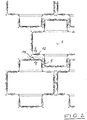
- the cross-shaped paving stones 1 shown in the figures are each provided with two opposing projecting stone sections 2 and 3, which have mutually perpendicular boundary surfaces, each comprising two side surfaces 6 and 9 and a respective front surface 7 and 8.
- a projecting first composite section 5 is arranged in an identical position, followed by an at least as long, free of a composite portion side surface portion in the direction of the formed with the adjacent projecting stone section 3 throat.
- These first composite sections are vertically arranged strip-shaped, protruding composite sections, which are approximately trapezoidal in horizontal section.
- the front surfaces 7 of these projecting stone sections 2 are each in the embodiment shown here with two pairs of two juxtaposed second composite sections 14 are provided, wherein the composite portions of a pair are arranged at a certain distance from each other.
- the front surfaces 8 of the other two projecting stone sections 3 likewise each have two pairs of two projecting second composite sections 10. These composite sections are arranged in a certain section from each other.
- the side surfaces 9 of the projecting stone portions 3 have a protruding composite portion 12 from one surface and two spaced-apart composite portions 11 on the opposite surface.
- the cross-shaped paving stone 1 shown here has two dummy joints 4, so that in the plan view three stone heads are formed.
- the two dummy joints 4 in this case run parallel to the front surfaces 7 of the two protruding stone sections 2.
- FIG. 1 shows the paving stones in a first stage to form a plaster bandage. At this stage, two adjacent stones are arranged so that the first composite sections of two projecting stone sections 2 of adjacent stones are spaced apart. The corresponding stones are then pushed against each other as indicated by the arrows in FIG. 1 is indicated.
- FIG. 2 shows the state in which the corresponding first composite sections 5 abut each other with their end faces.
- the stones are shifted in y-direction against each other and reach the in FIG. 3 shown location.
- the stones can then be moved again in the x-direction against each other, as indicated by the arrows in FIG. 3 is indicated.
- the in FIG. 4 shown end position reached, in which the two composite sections 5 of the neighboring stones abut each other.
- a plurality of small projecting portions 13 are arranged in the form of horizontally extending pedestals against which the final-stage composite portions abut. This prevents that the faces of the composite sections meet the respective side surfaces or front surfaces of the neighboring stone.
- FIG. 3 shows that, for example, the second composite portion 12 between the two second composite portions 14 in the figure is moved to the left, so that the first composite sections 5 can be moved to its final position.
- the second composite sections are therefore arranged at a distance from each other so that this movement is possible.
- the corresponding paving stones can therefore already be assembled on the production board or in the final laying of the patch in the manner described above in a bandage.
- a moving apart of the stones is possible only by a corresponding backward movement, so that the stones form an excellent association with each other.
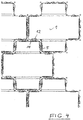
- FIG. 5 shows a plurality of such cross-shaped paving stones in a schematic plan view, wherein the corresponding composite sections have been omitted.
- the stone forms are indicated with corresponding dummy joints 4.
- the stones have a common base from which corresponding, separated by dummy joints stone heads extend upwards.
Claims (11)
- Pavé réalisé en forme de croix comportant à chaque fois deux parties de pavé saillantes opposées dotées de surfaces de délimitation verticales perpendiculaires l'une par rapport à l'autre, comprenant respectivement deux faces latérales et une face avant, caractérisé en ce qu'au niveau des faces latérales (6) de deux parties de pavé (2) saillantes opposées placées de façon identique, est disposée à chaque fois une première partie de liaison saillante (5) au niveau de laquelle s'adjoint dans la direction de la gorge formée sur la partie de pavé saillante voisine (3), une partie de face latérale au moins aussi longue, dépourvue de partie de liaison, et en ce que sur d'autres faces latérales (9) et/ou faces avant (7, 8) se trouvent deux parties de liaison saillantes (10, 11, 12, 14) qui permettent en coopération avec deux parties de liaison d'un pavé voisin pour la production d'un pavage, un décalage d'une première partie de liaison (5) du pavé voisin perpendiculairement à la face latérale correspondante (6) dans la position de liaison terminale avec la première partie de liaison (5) du pavé.
- Pavé selon la revendication 1, caractérisé en ce que les premières parties de liaison (5) sont conçues de façon à être plus larges que les deuxièmes parties de liaison (10, 11, 12, 14).
- Pavé selon la revendication 1 ou 2, caractérisé en ce que les premières parties de liaison (5) possèdent une face avant évoluant parallèlement à la face latérale (6) correspondante.
- Pavé selon l'une quelconque des revendications précédentes, caractérisé en ce que les deuxièmes parties de liaison (10, 11, 12, 14) sont disposées à une distance telle les unes des autres qu'un décalage parallèle des faces latérales/avant de deux parties de liaison de pavés voisin coopérant l'une avec l'autre est possible.
- Pavé selon l'une quelconque des revendications précédentes, caractérisé en ce qu'il possède un socle uniforme duquel partent plusieurs têtes de pavé séparées par des faux joints (4).
- Pavé selon l'une quelconque des revendications précédentes, caractérisé en ce que, au niveau adjacent ou entre des parties de liaison saillantes (5, 10, 11, 12, 14), de petites zones saillantes (13) sont prévues, qui entrent en contact avec les parties de liaison saillantes et assurent une distance de joint minimale lors de la réalisation d'un pavage.
- Pavé selon l'une quelconque des revendications précédentes, caractérisé en ce que, sur les faces avant (7, 8) des parties de pavé saillantes (2, 3), respectivement deux paires de deux parties de liaison (10, 14) sont disposées.
- Pavé selon l'une quelconque des revendications précédentes, caractérisé en ce que sur des faces latérales opposées (9) sur lesquelles aucune première partie de liaison (5) n'est disposée, sur une face latérale sont disposées deux (11) et sur la face latérale opposée, une partie de liaison (12).
- Pavé selon l'une quelconque des revendications précédentes, caractérisé en ce que respectivement, deux parties de pavé opposées (2, 3) sont conçues de même dimension.
- Pavé selon l'une quelconque des revendications précédentes, caractérisé en ce que les quatre parties de pavé saillantes sont toutes conçues de même dimension.
- Pavage produit à partir d'une multiplicité de pavés selon les revendications 1 à 10.
Applications Claiming Priority (2)
| Application Number | Priority Date | Filing Date | Title |
|---|---|---|---|
| DE102015015987.9A DE102015015987A1 (de) | 2015-12-10 | 2015-12-10 | Pflasterstein und hieraus hergestellter Pflasterverband |
| PCT/DE2016/000414 WO2017097280A1 (fr) | 2015-12-10 | 2016-11-22 | Pavé réalisé en forme de croix |
Publications (2)
| Publication Number | Publication Date |
|---|---|
| EP3387188A1 EP3387188A1 (fr) | 2018-10-17 |
| EP3387188B1 true EP3387188B1 (fr) | 2019-10-16 |
Family
ID=58266321
Family Applications (1)
| Application Number | Title | Priority Date | Filing Date |
|---|---|---|---|
| EP16845324.9A Not-in-force EP3387188B1 (fr) | 2015-12-10 | 2016-11-22 | Pavé réalisé en forme de croix |
Country Status (3)
| Country | Link |
|---|---|
| EP (1) | EP3387188B1 (fr) |
| DE (1) | DE102015015987A1 (fr) |
| WO (1) | WO2017097280A1 (fr) |
Family Cites Families (4)
| Publication number | Priority date | Publication date | Assignee | Title |
|---|---|---|---|---|
| DE7622670U1 (de) * | 1976-07-17 | 1976-12-16 | Betonwerk Stadthagen Friedrich Suthmeier, 3060 Stadthagen | Formstein für Verbundpflasterung |
| GB2306524A (en) * | 1995-10-25 | 1997-05-07 | U P S Ltd | Cruciform surfacing blocks |
| DE10205135A1 (de) * | 2002-02-07 | 2003-08-21 | Kombilith Gmbh Entwicklung & Verwertung | Pflasterstein mit mehreren gegeneinander versetzten Steinabschnitten |
| DE102010005018A1 (de) | 2010-01-19 | 2011-07-21 | Betonwerk Bad Lausick GmbH & Co. KG, 04651 | Pflasterstein und Verbund von Pflastersteinen |
-
2015
- 2015-12-10 DE DE102015015987.9A patent/DE102015015987A1/de not_active Withdrawn
-
2016
- 2016-11-22 EP EP16845324.9A patent/EP3387188B1/fr not_active Not-in-force
- 2016-11-22 WO PCT/DE2016/000414 patent/WO2017097280A1/fr active Application Filing
Non-Patent Citations (1)
| Title |
|---|
| None * |
Also Published As
| Publication number | Publication date |
|---|---|
| EP3387188A1 (fr) | 2018-10-17 |
| DE102015015987A1 (de) | 2017-06-14 |
| WO2017097280A1 (fr) | 2017-06-15 |
Similar Documents
| Publication | Publication Date | Title |
|---|---|---|
| EP2989403B1 (fr) | Système composite de pierres céramiques réfractaires | |
| EP3387188B1 (fr) | Pavé réalisé en forme de croix | |
| EP1088941B1 (fr) | Caniveau et élément de caniveau pour celui-ci | |
| CH616973A5 (en) | Interlocking-stone set for forming a floor covering | |
| DE102011110071A1 (de) | Verfahren zum Verlegen und Verbinden von Gebäudeplatten sowie Verriegelungsvorrichtung für Gebäudeplatten | |
| EP3690138B1 (fr) | Pavés pourvue d'aides à la pose, procédé de fabrication et revêtement | |
| CH704472A2 (de) | Mauersteinsystem. | |
| DE102005058087A1 (de) | Vorrichtung zur Abdeckung von Bodenfugen | |
| EP3199704B1 (fr) | Dallage disposé en segment | |
| DE202020102526U1 (de) | Mehrprofilpaneel | |
| DE19824556B4 (de) | Betonpflasterstein | |
| DE3311015C2 (fr) | ||
| DE3622258C2 (de) | Bauplatte | |
| EP2775031B1 (fr) | Élément en pierre pour la réalisation de gouttières multi-lignes, de bandes de pavés | |
| EP3830340B1 (fr) | Pavage à système composite | |
| DE202005006228U1 (de) | Dachkonstruktion für Gebäude, insbesondere für Industriegebäude mit großen Spannweiten | |
| DE202017105303U1 (de) | Rasenstegplatte | |
| DE4404080A1 (de) | Pflasterstein in polygoner, insbesondere rechteckiger Form | |
| EP3907346B1 (fr) | Panneau à profilés multiples | |
| DE202016101363U1 (de) | Formsteinverbundsystem | |
| WO2008119339A1 (fr) | Système de jonction | |
| EP1057935A1 (fr) | Pierre à paver | |
| AT409147B (de) | Betonpflasterstein | |
| DE10205135A1 (de) | Pflasterstein mit mehreren gegeneinander versetzten Steinabschnitten | |
| DE806482C (de) | Mauer aus in Abstand voneinander stehenden, durch Bauplatten gebildeten Schichten |
Legal Events
| Date | Code | Title | Description |
|---|---|---|---|
| STAA | Information on the status of an ep patent application or granted ep patent |
Free format text: STATUS: UNKNOWN |
|
| STAA | Information on the status of an ep patent application or granted ep patent |
Free format text: STATUS: THE INTERNATIONAL PUBLICATION HAS BEEN MADE |
|
| PUAI | Public reference made under article 153(3) epc to a published international application that has entered the european phase |
Free format text: ORIGINAL CODE: 0009012 |
|
| STAA | Information on the status of an ep patent application or granted ep patent |
Free format text: STATUS: REQUEST FOR EXAMINATION WAS MADE |
|
| 17P | Request for examination filed |
Effective date: 20180703 |
|
| AK | Designated contracting states |
Kind code of ref document: A1 Designated state(s): AL AT BE BG CH CY CZ DE DK EE ES FI FR GB GR HR HU IE IS IT LI LT LU LV MC MK MT NL NO PL PT RO RS SE SI SK SM TR |
|
| AX | Request for extension of the european patent |
Extension state: BA ME |
|
| DAV | Request for validation of the european patent (deleted) | ||
| DAX | Request for extension of the european patent (deleted) | ||
| GRAP | Despatch of communication of intention to grant a patent |
Free format text: ORIGINAL CODE: EPIDOSNIGR1 |
|
| STAA | Information on the status of an ep patent application or granted ep patent |
Free format text: STATUS: GRANT OF PATENT IS INTENDED |
|
| INTG | Intention to grant announced |
Effective date: 20190507 |
|
| GRAS | Grant fee paid |
Free format text: ORIGINAL CODE: EPIDOSNIGR3 |
|
| GRAA | (expected) grant |
Free format text: ORIGINAL CODE: 0009210 |
|
| STAA | Information on the status of an ep patent application or granted ep patent |
Free format text: STATUS: THE PATENT HAS BEEN GRANTED |
|
| AK | Designated contracting states |
Kind code of ref document: B1 Designated state(s): AL AT BE BG CH CY CZ DE DK EE ES FI FR GB GR HR HU IE IS IT LI LT LU LV MC MK MT NL NO PL PT RO RS SE SI SK SM TR |
|
| REG | Reference to a national code |
Ref country code: GB Ref legal event code: FG4D Free format text: NOT ENGLISH |
|
| REG | Reference to a national code |
Ref country code: CH Ref legal event code: EP |
|
| REG | Reference to a national code |
Ref country code: DE Ref legal event code: R096 Ref document number: 502016007168 Country of ref document: DE |
|
| REG | Reference to a national code |
Ref country code: IE Ref legal event code: FG4D Free format text: LANGUAGE OF EP DOCUMENT: GERMAN |
|
| REG | Reference to a national code |
Ref country code: AT Ref legal event code: REF Ref document number: 1191366 Country of ref document: AT Kind code of ref document: T Effective date: 20191115 |
|
| REG | Reference to a national code |
Ref country code: NL Ref legal event code: MP Effective date: 20191016 |
|
| REG | Reference to a national code |
Ref country code: LT Ref legal event code: MG4D |
|
| PG25 | Lapsed in a contracting state [announced via postgrant information from national office to epo] |
Ref country code: NL Free format text: LAPSE BECAUSE OF FAILURE TO SUBMIT A TRANSLATION OF THE DESCRIPTION OR TO PAY THE FEE WITHIN THE PRESCRIBED TIME-LIMIT Effective date: 20191016 Ref country code: PL Free format text: LAPSE BECAUSE OF FAILURE TO SUBMIT A TRANSLATION OF THE DESCRIPTION OR TO PAY THE FEE WITHIN THE PRESCRIBED TIME-LIMIT Effective date: 20191016 Ref country code: LT Free format text: LAPSE BECAUSE OF FAILURE TO SUBMIT A TRANSLATION OF THE DESCRIPTION OR TO PAY THE FEE WITHIN THE PRESCRIBED TIME-LIMIT Effective date: 20191016 Ref country code: NO Free format text: LAPSE BECAUSE OF FAILURE TO SUBMIT A TRANSLATION OF THE DESCRIPTION OR TO PAY THE FEE WITHIN THE PRESCRIBED TIME-LIMIT Effective date: 20200116 Ref country code: GR Free format text: LAPSE BECAUSE OF FAILURE TO SUBMIT A TRANSLATION OF THE DESCRIPTION OR TO PAY THE FEE WITHIN THE PRESCRIBED TIME-LIMIT Effective date: 20200117 Ref country code: FI Free format text: LAPSE BECAUSE OF FAILURE TO SUBMIT A TRANSLATION OF THE DESCRIPTION OR TO PAY THE FEE WITHIN THE PRESCRIBED TIME-LIMIT Effective date: 20191016 Ref country code: PT Free format text: LAPSE BECAUSE OF FAILURE TO SUBMIT A TRANSLATION OF THE DESCRIPTION OR TO PAY THE FEE WITHIN THE PRESCRIBED TIME-LIMIT Effective date: 20200217 Ref country code: LV Free format text: LAPSE BECAUSE OF FAILURE TO SUBMIT A TRANSLATION OF THE DESCRIPTION OR TO PAY THE FEE WITHIN THE PRESCRIBED TIME-LIMIT Effective date: 20191016 Ref country code: SE Free format text: LAPSE BECAUSE OF FAILURE TO SUBMIT A TRANSLATION OF THE DESCRIPTION OR TO PAY THE FEE WITHIN THE PRESCRIBED TIME-LIMIT Effective date: 20191016 Ref country code: BG Free format text: LAPSE BECAUSE OF FAILURE TO SUBMIT A TRANSLATION OF THE DESCRIPTION OR TO PAY THE FEE WITHIN THE PRESCRIBED TIME-LIMIT Effective date: 20200116 |
|
| PG25 | Lapsed in a contracting state [announced via postgrant information from national office to epo] |
Ref country code: RS Free format text: LAPSE BECAUSE OF FAILURE TO SUBMIT A TRANSLATION OF THE DESCRIPTION OR TO PAY THE FEE WITHIN THE PRESCRIBED TIME-LIMIT Effective date: 20191016 Ref country code: IS Free format text: LAPSE BECAUSE OF FAILURE TO SUBMIT A TRANSLATION OF THE DESCRIPTION OR TO PAY THE FEE WITHIN THE PRESCRIBED TIME-LIMIT Effective date: 20200224 Ref country code: HR Free format text: LAPSE BECAUSE OF FAILURE TO SUBMIT A TRANSLATION OF THE DESCRIPTION OR TO PAY THE FEE WITHIN THE PRESCRIBED TIME-LIMIT Effective date: 20191016 |
|
| PG25 | Lapsed in a contracting state [announced via postgrant information from national office to epo] |
Ref country code: AL Free format text: LAPSE BECAUSE OF FAILURE TO SUBMIT A TRANSLATION OF THE DESCRIPTION OR TO PAY THE FEE WITHIN THE PRESCRIBED TIME-LIMIT Effective date: 20191016 |
|
| REG | Reference to a national code |
Ref country code: CH Ref legal event code: PL |
|
| REG | Reference to a national code |
Ref country code: DE Ref legal event code: R097 Ref document number: 502016007168 Country of ref document: DE |
|
| PG2D | Information on lapse in contracting state deleted |
Ref country code: IS |
|
| PG25 | Lapsed in a contracting state [announced via postgrant information from national office to epo] |
Ref country code: EE Free format text: LAPSE BECAUSE OF FAILURE TO SUBMIT A TRANSLATION OF THE DESCRIPTION OR TO PAY THE FEE WITHIN THE PRESCRIBED TIME-LIMIT Effective date: 20191016 Ref country code: LI Free format text: LAPSE BECAUSE OF NON-PAYMENT OF DUE FEES Effective date: 20191130 Ref country code: DK Free format text: LAPSE BECAUSE OF FAILURE TO SUBMIT A TRANSLATION OF THE DESCRIPTION OR TO PAY THE FEE WITHIN THE PRESCRIBED TIME-LIMIT Effective date: 20191016 Ref country code: CH Free format text: LAPSE BECAUSE OF NON-PAYMENT OF DUE FEES Effective date: 20191130 Ref country code: MC Free format text: LAPSE BECAUSE OF FAILURE TO SUBMIT A TRANSLATION OF THE DESCRIPTION OR TO PAY THE FEE WITHIN THE PRESCRIBED TIME-LIMIT Effective date: 20191016 Ref country code: LU Free format text: LAPSE BECAUSE OF NON-PAYMENT OF DUE FEES Effective date: 20191122 Ref country code: ES Free format text: LAPSE BECAUSE OF FAILURE TO SUBMIT A TRANSLATION OF THE DESCRIPTION OR TO PAY THE FEE WITHIN THE PRESCRIBED TIME-LIMIT Effective date: 20191016 Ref country code: RO Free format text: LAPSE BECAUSE OF FAILURE TO SUBMIT A TRANSLATION OF THE DESCRIPTION OR TO PAY THE FEE WITHIN THE PRESCRIBED TIME-LIMIT Effective date: 20191016 Ref country code: CZ Free format text: LAPSE BECAUSE OF FAILURE TO SUBMIT A TRANSLATION OF THE DESCRIPTION OR TO PAY THE FEE WITHIN THE PRESCRIBED TIME-LIMIT Effective date: 20191016 Ref country code: IS Free format text: LAPSE BECAUSE OF FAILURE TO SUBMIT A TRANSLATION OF THE DESCRIPTION OR TO PAY THE FEE WITHIN THE PRESCRIBED TIME-LIMIT Effective date: 20200216 |
|
| PLBE | No opposition filed within time limit |
Free format text: ORIGINAL CODE: 0009261 |
|
| REG | Reference to a national code |
Ref country code: BE Ref legal event code: MM Effective date: 20191130 |
|
| STAA | Information on the status of an ep patent application or granted ep patent |
Free format text: STATUS: NO OPPOSITION FILED WITHIN TIME LIMIT |
|
| PG25 | Lapsed in a contracting state [announced via postgrant information from national office to epo] |
Ref country code: SM Free format text: LAPSE BECAUSE OF FAILURE TO SUBMIT A TRANSLATION OF THE DESCRIPTION OR TO PAY THE FEE WITHIN THE PRESCRIBED TIME-LIMIT Effective date: 20191016 Ref country code: SK Free format text: LAPSE BECAUSE OF FAILURE TO SUBMIT A TRANSLATION OF THE DESCRIPTION OR TO PAY THE FEE WITHIN THE PRESCRIBED TIME-LIMIT Effective date: 20191016 Ref country code: IT Free format text: LAPSE BECAUSE OF FAILURE TO SUBMIT A TRANSLATION OF THE DESCRIPTION OR TO PAY THE FEE WITHIN THE PRESCRIBED TIME-LIMIT Effective date: 20191016 |
|
| 26N | No opposition filed |
Effective date: 20200717 |
|
| PG25 | Lapsed in a contracting state [announced via postgrant information from national office to epo] |
Ref country code: IE Free format text: LAPSE BECAUSE OF NON-PAYMENT OF DUE FEES Effective date: 20191122 Ref country code: FR Free format text: LAPSE BECAUSE OF NON-PAYMENT OF DUE FEES Effective date: 20191216 |
|
| PG25 | Lapsed in a contracting state [announced via postgrant information from national office to epo] |
Ref country code: BE Free format text: LAPSE BECAUSE OF NON-PAYMENT OF DUE FEES Effective date: 20191130 Ref country code: SI Free format text: LAPSE BECAUSE OF FAILURE TO SUBMIT A TRANSLATION OF THE DESCRIPTION OR TO PAY THE FEE WITHIN THE PRESCRIBED TIME-LIMIT Effective date: 20191016 |
|
| REG | Reference to a national code |
Ref country code: DE Ref legal event code: R082 Ref document number: 502016007168 Country of ref document: DE Representative=s name: HAUCK PATENT- UND RECHTSANWAELTE, DE |
|
| PG25 | Lapsed in a contracting state [announced via postgrant information from national office to epo] |
Ref country code: CY Free format text: LAPSE BECAUSE OF FAILURE TO SUBMIT A TRANSLATION OF THE DESCRIPTION OR TO PAY THE FEE WITHIN THE PRESCRIBED TIME-LIMIT Effective date: 20191016 |
|
| GBPC | Gb: european patent ceased through non-payment of renewal fee |
Effective date: 20201122 |
|
| PG25 | Lapsed in a contracting state [announced via postgrant information from national office to epo] |
Ref country code: HU Free format text: LAPSE BECAUSE OF FAILURE TO SUBMIT A TRANSLATION OF THE DESCRIPTION OR TO PAY THE FEE WITHIN THE PRESCRIBED TIME-LIMIT; INVALID AB INITIO Effective date: 20161122 Ref country code: MT Free format text: LAPSE BECAUSE OF FAILURE TO SUBMIT A TRANSLATION OF THE DESCRIPTION OR TO PAY THE FEE WITHIN THE PRESCRIBED TIME-LIMIT Effective date: 20191016 |
|
| PG25 | Lapsed in a contracting state [announced via postgrant information from national office to epo] |
Ref country code: GB Free format text: LAPSE BECAUSE OF NON-PAYMENT OF DUE FEES Effective date: 20201122 |
|
| PGFP | Annual fee paid to national office [announced via postgrant information from national office to epo] |
Ref country code: DE Payment date: 20220113 Year of fee payment: 6 |
|
| PG25 | Lapsed in a contracting state [announced via postgrant information from national office to epo] |
Ref country code: TR Free format text: LAPSE BECAUSE OF FAILURE TO SUBMIT A TRANSLATION OF THE DESCRIPTION OR TO PAY THE FEE WITHIN THE PRESCRIBED TIME-LIMIT Effective date: 20191016 |
|
| PG25 | Lapsed in a contracting state [announced via postgrant information from national office to epo] |
Ref country code: MK Free format text: LAPSE BECAUSE OF FAILURE TO SUBMIT A TRANSLATION OF THE DESCRIPTION OR TO PAY THE FEE WITHIN THE PRESCRIBED TIME-LIMIT Effective date: 20191016 |
|
| REG | Reference to a national code |
Ref country code: AT Ref legal event code: MM01 Ref document number: 1191366 Country of ref document: AT Kind code of ref document: T Effective date: 20211122 |
|
| PG25 | Lapsed in a contracting state [announced via postgrant information from national office to epo] |
Ref country code: AT Free format text: LAPSE BECAUSE OF NON-PAYMENT OF DUE FEES Effective date: 20211122 |
|
| REG | Reference to a national code |
Ref country code: DE Ref legal event code: R119 Ref document number: 502016007168 Country of ref document: DE |
|
| PG25 | Lapsed in a contracting state [announced via postgrant information from national office to epo] |
Ref country code: DE Free format text: LAPSE BECAUSE OF NON-PAYMENT OF DUE FEES Effective date: 20230601 |