EP3387188B1 - Cruciform paving stone - Google Patents
Cruciform paving stone Download PDFInfo
- Publication number
- EP3387188B1 EP3387188B1 EP16845324.9A EP16845324A EP3387188B1 EP 3387188 B1 EP3387188 B1 EP 3387188B1 EP 16845324 A EP16845324 A EP 16845324A EP 3387188 B1 EP3387188 B1 EP 3387188B1
- Authority
- EP
- European Patent Office
- Prior art keywords
- stone
- projecting
- sections
- paving
- composite
- Prior art date
- Legal status (The legal status is an assumption and is not a legal conclusion. Google has not performed a legal analysis and makes no representation as to the accuracy of the status listed.)
- Not-in-force
Links
Images


Classifications
-
- E—FIXED CONSTRUCTIONS
- E01—CONSTRUCTION OF ROADS, RAILWAYS, OR BRIDGES
- E01C—CONSTRUCTION OF, OR SURFACES FOR, ROADS, SPORTS GROUNDS, OR THE LIKE; MACHINES OR AUXILIARY TOOLS FOR CONSTRUCTION OR REPAIR
- E01C5/00—Pavings made of prefabricated single units
-
- E—FIXED CONSTRUCTIONS
- E01—CONSTRUCTION OF ROADS, RAILWAYS, OR BRIDGES
- E01C—CONSTRUCTION OF, OR SURFACES FOR, ROADS, SPORTS GROUNDS, OR THE LIKE; MACHINES OR AUXILIARY TOOLS FOR CONSTRUCTION OR REPAIR
- E01C5/00—Pavings made of prefabricated single units
- E01C5/06—Pavings made of prefabricated single units made of units with cement or like binders
-
- E—FIXED CONSTRUCTIONS
- E01—CONSTRUCTION OF ROADS, RAILWAYS, OR BRIDGES
- E01C—CONSTRUCTION OF, OR SURFACES FOR, ROADS, SPORTS GROUNDS, OR THE LIKE; MACHINES OR AUXILIARY TOOLS FOR CONSTRUCTION OR REPAIR
- E01C2201/00—Paving elements
- E01C2201/02—Paving elements having fixed spacing features
-
- E—FIXED CONSTRUCTIONS
- E01—CONSTRUCTION OF ROADS, RAILWAYS, OR BRIDGES
- E01C—CONSTRUCTION OF, OR SURFACES FOR, ROADS, SPORTS GROUNDS, OR THE LIKE; MACHINES OR AUXILIARY TOOLS FOR CONSTRUCTION OR REPAIR
- E01C2201/00—Paving elements
- E01C2201/06—Sets of paving elements
-
- E—FIXED CONSTRUCTIONS
- E01—CONSTRUCTION OF ROADS, RAILWAYS, OR BRIDGES
- E01C—CONSTRUCTION OF, OR SURFACES FOR, ROADS, SPORTS GROUNDS, OR THE LIKE; MACHINES OR AUXILIARY TOOLS FOR CONSTRUCTION OR REPAIR
- E01C2201/00—Paving elements
- E01C2201/16—Elements joined together
-
- E—FIXED CONSTRUCTIONS
- E01—CONSTRUCTION OF ROADS, RAILWAYS, OR BRIDGES
- E01C—CONSTRUCTION OF, OR SURFACES FOR, ROADS, SPORTS GROUNDS, OR THE LIKE; MACHINES OR AUXILIARY TOOLS FOR CONSTRUCTION OR REPAIR
- E01C2201/00—Paving elements
- E01C2201/16—Elements joined together
- E01C2201/162—Elements joined together with breaking lines
Definitions
- the present invention relates to a cross-shaped paving stone with two opposite projecting stone sections with mutually perpendicular, each two side surfaces and a front surface comprising vertical boundary surfaces.
- Such paving stones are well known. They have a walkable or passable top and an opposite bottom and a plurality of vertically arranged side surfaces and front surfaces. Through the cross shape can be made of such paving stones plaster bandages that have no continuous joints and thus have a good gearing effect. In particular, such paving stones are therefore suitable for heavy duty paving.
- a so-called heavy duty pavement is often desired, which gives the impression of high load-bearing capacity even on the outside.
- larger Stone thicknesses as well as special stone floor plans play a decisive role.
- TRILOC plaster in which the individual paving stones have an approximately triangular plan, and the so-called UNI Optiloc plaster, come in the angular paving stones are used.
- From the DE 102 05 135 A1 is a cross-shaped paving stone with two opposite projecting stone sections with mutually perpendicular, each having two side surfaces and a front surface comprehensive, vertical boundary surfaces known.
- this known paving stone projecting composite sections are arranged on all side surfaces and front surfaces of the protruding stone sections, but the composite sections of two opposing projecting stone sections are not arranged in an identical position.
- the GB 2 306 524 A describes a cross-shaped paving stone with two opposite projecting stone sections. On the side surfaces of two opposing protruding stone sections are arranged in an identical position, a protruding composite portion and a recessed composite portion.
- the FR 2 358 510 A1 describes a cross-shaped paving stone with two oppositely arranged projecting stone sections, wherein also here on the side surfaces of two opposing projecting stone sections in an identical position a projecting and a recessed composite section are arranged.
- the present invention has for its object to provide a paving stone of the type described above, with a particularly well-toothed plaster bandage can be reached.
- a protruding first composite portion is arranged at the towards the throat formed with the adjacent protruding stone portion at least one just as long, from a composite portion free side surface portion connects, and that are on other side surfaces and / or front surfaces projecting second composite sections, in cooperation with second composite sections of a neighboring stone for the production of a plaster bandage displacement of a first composite portion of the neighboring stone perpendicular to the corresponding side surface in the Allow final composite position with the first composite portion of the paving stone.
- the paving stone according to the invention which is particularly suitable for a heavy duty pavement and can absorb high loads, is cross-shaped in plan view and provided on its side surfaces and front surfaces with a special system of strip-shaped, vertically extending composite sections.
- the paving stone formed according to the invention therefore has a double composite system, which is formed on the one hand by the cross shape and on the other hand by the special composite sections. It is understood that already by the cross shape, a corresponding toothing effect is achieved and that the provided composite sections provide an additional toothing effect.
- a particularly well-toothed plaster bandage can thus be produced.
- several paving stones can be pushed together on a production board so that the composite sections of adjacent stones engage each other and the stones can be clipped accordingly.
- the special arrangement of the composite sections ensures that the stones must be placed in a special way and can not be separated easily by simple movement processes again.
- a special zigzag-shaped movement is required for assembling or juxtaposing and separating the stones, which is composed, for example, of two movement processes in the x-direction (horizontal in the drawing) and an intermediate movement in the y-direction (vertically in the drawing).
- the plaster formed is well secured by the circulating composite system of cross-shaped stones in the x and y direction against train.
- the bricks on the production board can not easily be pushed together, since the composite system engages after being pushed together in the first direction (x-direction) and thereby no longer permits a collapse in the second direction (y-direction).
- first composite sections are arranged in an identical position on the side surfaces of two opposite projecting stone sections are arranged.
- first composite sections are pushed together in the first direction (x-direction), therefore, the first composite sections abut each other, so that closing the composite system in this direction is not possible.
- the stones in the second direction are pushed together in this direction until closing of the composite system.
- the first composite sections which collided during the first displacement, are laterally shifted so that they can now grip.
- the second composite sections closing in the second displacement process must be positioned with sufficient lateral distances such that a further displacement in the first direction (x direction) is also possible in this direction until the connection system is closed.
- the pushing together thus takes place in three steps z-shaped and closes the whole system so that a pulling apart of the stones neither in the x-direction nor in y-direction is readily possible since the attacking horizontal forces act only in one direction and such Z Movement can not understand.
- the stones can therefore not be pushed together on the production board or on the construction site in the usual way, since the composite system, for example, pushed together in the x-direction, so closes that pushing together in the y-direction is no longer possible.
- the stones are therefore pushed together so that in a first displacement process in the x direction, the first composite sections collide, but due to their width, the intervention of the composite sections is prevented.
- the stones are pushed together in the y-direction until the second composite sections whose lateral distance from one another is dimensioned such that in a third displacement again in the x-direction in the second displacement relative to each other shifted first composite sections until now possible Intervention can be pushed together.
- the same Z-shaped movement is required to separate the stones or to open the joints.
- the first composite sections are preferably wider than the second composite sections.
- the first composite sections have an end face extending parallel to the corresponding side face.
- the second composite sections allow the mentioned second shift in the x direction.
- the second composite sections are arranged at such a distance from each other that a side / front surface parallel displacement of cooperating second composite sections of adjacent stones against each other is possible.
- the paving stone formed according to the invention has a uniform base, from which several stone heads separated by dummy joints emanate. Any design options in relation to the stone heads are possible. For example, a subdivision into three, four or more stone heads can be made. Of course you can the base also be provided with a single stone head without dummy joints.
- formed paving stone adjacent to or between projecting composite sections small projecting areas are provided, which are contacted in the preparation of a plaster bandage of the above composite sections of a neighboring stone and ensure a minimum joint spacing.
- the arrangement of such small protruding areas is known per se in rectangular bricks with corresponding composite systems.
- the protruding areas can be formed, for example, as a horizontally extending base.
- the composite sections are formed in the paving stone according to the invention as vertical strips, which strips do not have to extend beyond the full height of the stone.
- the strip-shaped composite sections preferably have a triangular shape, a trapezoidal shape or a semicircular shape.
- the first composite sections are preferably trapezoidal in horizontal section, while the second composite sections are preferably approximately triangular in horizontal section.
- the second composite sections are arranged offset from one another on corresponding opposite front surfaces or side surfaces.
- the first Composite sections on opposite side surfaces not offset from each other.
- the offset of the second composite sections or their distances or gaps are, as mentioned, formed so that a corresponding displacement in the side / front surface parallel direction is possible so that the first composite sections can be brought into their final composite position.
- two pairs of second composite sections are respectively arranged on the front surfaces of the protruding stone sections. When the stones are put together, these composite sections interact with corresponding composite sections of the neighboring stone.
- two composite sections are arranged on one side surface on opposite side surfaces, on which no first composite sections are arranged, and one composite section on the opposite side surface. These composite sections also interact with the adjoining stones with corresponding composite sections of neighboring stones.
- all four projecting stone sections are of equal size, so that arise symmetrical conditions.
- two opposite projecting stone sections are the same size.
- opposing protruding stone sections can be designed unequal size, or it can, for example of the four protruding stone sections all sections have different sizes.
- the above-described paving stone according to the invention described above is preferably made of concrete in the usual way.
- the production takes place in special forms. After the stones have been formed, they are placed on a production board, pushed together and clamped in the manner described above. The corresponding bracketed units are then machine-laying.
- the present invention further relates to a plaster dressing made from a plurality of such paving stones.
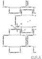
- the cross-shaped paving stones 1 shown in the figures are each provided with two opposing projecting stone sections 2 and 3, which have mutually perpendicular boundary surfaces, each comprising two side surfaces 6 and 9 and a respective front surface 7 and 8.
- a projecting first composite section 5 is arranged in an identical position, followed by an at least as long, free of a composite portion side surface portion in the direction of the formed with the adjacent projecting stone section 3 throat.
- These first composite sections are vertically arranged strip-shaped, protruding composite sections, which are approximately trapezoidal in horizontal section.
- the front surfaces 7 of these projecting stone sections 2 are each in the embodiment shown here with two pairs of two juxtaposed second composite sections 14 are provided, wherein the composite portions of a pair are arranged at a certain distance from each other.
- the front surfaces 8 of the other two projecting stone sections 3 likewise each have two pairs of two projecting second composite sections 10. These composite sections are arranged in a certain section from each other.
- the side surfaces 9 of the projecting stone portions 3 have a protruding composite portion 12 from one surface and two spaced-apart composite portions 11 on the opposite surface.
- the cross-shaped paving stone 1 shown here has two dummy joints 4, so that in the plan view three stone heads are formed.
- the two dummy joints 4 in this case run parallel to the front surfaces 7 of the two protruding stone sections 2.
- FIG. 1 shows the paving stones in a first stage to form a plaster bandage. At this stage, two adjacent stones are arranged so that the first composite sections of two projecting stone sections 2 of adjacent stones are spaced apart. The corresponding stones are then pushed against each other as indicated by the arrows in FIG. 1 is indicated.
- FIG. 2 shows the state in which the corresponding first composite sections 5 abut each other with their end faces.
- the stones are shifted in y-direction against each other and reach the in FIG. 3 shown location.
- the stones can then be moved again in the x-direction against each other, as indicated by the arrows in FIG. 3 is indicated.
- the in FIG. 4 shown end position reached, in which the two composite sections 5 of the neighboring stones abut each other.
- a plurality of small projecting portions 13 are arranged in the form of horizontally extending pedestals against which the final-stage composite portions abut. This prevents that the faces of the composite sections meet the respective side surfaces or front surfaces of the neighboring stone.
- FIG. 3 shows that, for example, the second composite portion 12 between the two second composite portions 14 in the figure is moved to the left, so that the first composite sections 5 can be moved to its final position.
- the second composite sections are therefore arranged at a distance from each other so that this movement is possible.
- the corresponding paving stones can therefore already be assembled on the production board or in the final laying of the patch in the manner described above in a bandage.
- a moving apart of the stones is possible only by a corresponding backward movement, so that the stones form an excellent association with each other.
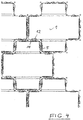
- FIG. 5 shows a plurality of such cross-shaped paving stones in a schematic plan view, wherein the corresponding composite sections have been omitted.
- the stone forms are indicated with corresponding dummy joints 4.
- the stones have a common base from which corresponding, separated by dummy joints stone heads extend upwards.
Description
Die vorliegende Erfindung betrifft einen kreuzförmig ausgebildeten Pflasterstein mit je zwei gegenüber angeordneten vorstehenden Steinabschnitten mit senkrecht zueinander verlaufenden, jeweils zwei Seitenflächen und eine Vorderfläche umfassenden, vertikalen Begrenzungsflächen.The present invention relates to a cross-shaped paving stone with two opposite projecting stone sections with mutually perpendicular, each two side surfaces and a front surface comprising vertical boundary surfaces.
Derartige Pflastersteine sind allgemein bekannt. Sie besitzen eine begehbare oder befahrbare Oberseite sowie eine gegenüberliegende Unterseite und eine Vielzahl von hierzu vertikal angeordneten Seitenflächen und Vorderflächen. Durch die Kreuzform lassen sich aus solchen Pflastersteinen Pflasterverbände herstellen, die keine durchlaufenden Fugen besitzen und somit einen guten Verzahnungseffekt aufweisen. Insbesondere sind derartige Pflastersteine daher für Schwerlastpflaster geeignet.Such paving stones are well known. They have a walkable or passable top and an opposite bottom and a plurality of vertically arranged side surfaces and front surfaces. Through the cross shape can be made of such paving stones plaster bandages that have no continuous joints and thus have a good gearing effect. In particular, such paving stones are therefore suitable for heavy duty paving.
Für besonders hoch belastete Flächen, wie Hafenanlagen, Containerlager und spezielle Industrieflächen, wird oft ein sogenanntes Schwerlastpflaster gewünscht, das schon rein äußerlich den Eindruck hoher Belastbarkeit vermittelt. Größere Steinstärken sowie besondere Stein-Grundrissformen spielen dabei eine entscheidende Rolle. Bekannt ist hierbei das sogenannte TRILOC-Pflaster, bei dem die einzelnen Pflastersteine einen etwa dreieckförmigen Grundriss besitzen, und das sogenannte UNI-Optiloc-Pflaster, bei dem winkelförmige Pflastersteine zum Einsatz kommen.For areas subject to particularly high loads, such as port facilities, container warehouses and special industrial areas, a so-called heavy duty pavement is often desired, which gives the impression of high load-bearing capacity even on the outside. larger Stone thicknesses as well as special stone floor plans play a decisive role. Known here is the so-called TRILOC plaster, in which the individual paving stones have an approximately triangular plan, and the so-called UNI Optiloc plaster, come in the angular paving stones are used.
Die bekannten Pflastersteine für Schwerlastpflaster lassen jedoch noch Wünsche in Bezug auf das Belastungsvermögen sowie die Gestaltungsmöglichkeiten offen. Insbesondere findet bei winkelförmigen Pflastersteinen eine unsymmetrische Verteilung der angreifenden Horizontallasten statt, die zu Drehtendenzen bei den verlegten Steinen führen. Die Ausführungsformen mit speziellen dreieckförmigen Grundrissen lassen in Bezug auf die gestalterische Qualität der Steine Wünsche offen, da sie nicht für jedes Umfeld geeignet sind.However, the well-known paving stones for heavy duty pavement still leaves desires in terms of load capacity and design options open. In particular, an asymmetrical distribution of the attacking horizontal loads takes place in angular paving stones, which lead to tendencies of rotation in the laid stones. The embodiments with special triangular floor plans leave something to be desired in terms of the design quality of the stones, since they are not suitable for any environment.
Aus der
Es ist bekannt, Pflastersteine in Rechteckform auf ihren Seitenflächen mit leistenförmigen vorstehenden Verbundabschnitten zu versehen, um auf diese Weise eine Verschiebesicherung zwischen im Pflasterverband verlegten benachbarten Pflastersteinen zu erreichen. Diese Verbundabschnitte können die ebenen Seitenflächen des benachbarten Pflastersteines kontaktieren. In der Regel ist jedoch ein derartiger Kontakt unerwünscht, da es hierdurch zur ungepufferten Übertragung von horizontalen Lasten zwischen den Steinen kommt, die Risse und Brüche bewirken. Bevorzugt wird daher eine Verlegung, bei der die Verbundabschnitte den Nachbarstein nicht kontaktieren, sondern sich lediglich in die Fuge hineinerstrecken. Bei gefüllter Fuge wird daher eine entsprechende Verschiebesicherung gebildet.It is known to provide paving stones in a rectangular shape on their side surfaces with strip-shaped protruding composite sections, in order to achieve in this way a displacement protection between laid in the plaster bandage adjacent paving stones. These composite sections can contact the flat side surfaces of the adjacent paving stone. In general, however, such a contact is undesirable because it thereby unbuffered Transfer of horizontal loads occurs between the stones causing cracks and breaks. Preference is therefore given to a laying in which the composite sections do not contact the neighboring stone, but merely extend into the joint. When filled gap therefore a corresponding displacement protection is formed.
Um beim Verlegen von derartigen Rechtecksteinen mit Verbundabschnitten einen entsprechenden Fugenabstand zwischen den Steinen einzuhalten, ist es bereits bekannt, zwischen derartigen Verbundabschnitten geringfügig vorstehende Bereiche, beispielsweise als Sockel, vorzusehen. Beim Verlegen stößt daher ein Verbundabschnitt des einen Steines gegen den geringfügig vorstehenden Bereich des anderen Steines. Auf diese Weise wird die entsprechende Fugenbreite automatisch eingehalten und der Kontakt zwischen benachbarten Steinen auf ein Minimum beschränkt.In order to maintain a corresponding joint spacing between the bricks when laying such rectangular bricks with composite sections, it is already known to provide slightly protruding areas, for example as a base, between such composite sections. When laying, therefore, a composite portion of the one stone abuts against the slightly protruding portion of the other stone. In this way, the corresponding joint width is automatically maintained and the contact between adjacent stones is kept to a minimum.
Derartige Verbundsysteme kommen bei "normalen" Rechtecksteinen zum Einsatz.Such composite systems are used in "normal" rectangular bricks.
Auch bei dem vorstehend beschriebenen bekannten H-förmigen Pflasterstein ist es bekannt, auf den Seitenflächen des Steines leistenförmige Verbundabschnitte vorzusehen. Diese Verbundabschnitte wirken dabei im Pflasterverband mit entsprechenden Verbundabschnitten eines Nachbarsteines zusammen. Damit die Verbundabschnitte ineinandergreifen, sind sie auf gegenüberliegenden Seitenflächen des Steines versetzt zueinander angeordnet.Also in the known H-shaped paving stone described above, it is known to provide strip-shaped composite sections on the side surfaces of the stone. These composite sections act together in the plaster bandage with corresponding composite sections of a neighboring stone. In order that the composite sections intermesh, they are arranged offset on opposite side surfaces of the stone to each other.
Aus der
Die
Auch die
Der vorliegenden Erfindung liegt die Aufgabe zugrunde, einen Pflasterstein der eingangs beschriebenen Art zu schaffen, mit dem ein besonders gut verzahnter Pflasterverband erreichbar ist.The present invention has for its object to provide a paving stone of the type described above, with a particularly well-toothed plaster bandage can be reached.
Diese Aufgabe wird erfindungsgemäß bei einem Pflasterstein der angegebenen Art dadurch gelöst, dass an den Seitenflächen von zwei gegenüber angeordneten vorstehenden Steinabschnitten in identischer Lage jeweils ein vorstehender erster Verbundabschnitt angeordnet ist, an den sich in Richtung auf die mit dem benachbarten vorstehenden Steinabschnitt gebildete Kehle ein mindestens genauso langer, von einem Verbundabschnitt freier Seitenflächenabschnitt anschließt, und dass sich auf weiteren Seitenflächen und/oder Vorderflächen vorstehende zweite Verbundabschnitte befinden, die in Zusammenwirkung mit zweiten Verbundabschnitten eines Nachbarsteines zur Herstellung eines Pflasterverbandes eine Verschiebung eines ersten Verbundabschnittes des Nachbarsteines senkrecht zur entsprechenden Seitenfläche in die End-Verbundposition mit dem ersten Verbundabschnitt des Pflastersteines zulassen.This object is achieved in a paving stone of the specified type in that on the side surfaces of two opposing protruding stone sections in an identical position each a protruding first composite portion is arranged at the towards the throat formed with the adjacent protruding stone portion at least one just as long, from a composite portion free side surface portion connects, and that are on other side surfaces and / or front surfaces projecting second composite sections, in cooperation with second composite sections of a neighboring stone for the production of a plaster bandage displacement of a first composite portion of the neighboring stone perpendicular to the corresponding side surface in the Allow final composite position with the first composite portion of the paving stone.
Der erfindungsgemäß ausgebildete Pflasterstein, der insbesondere für ein Schwerlastpflaster geeignet ist und hohe Belastungen aufnehmen kann, ist in der Draufsicht kreuzförmig ausgebildet und an seinen Seitenflächen und Vorderflächen mit einem speziellen System von leistenförmigen, sich vertikal erstreckenden Verbundabschnitten versehen. Der erfindungsgemäß ausgebildete Pflasterstein besitzt daher ein doppeltes Verbundsystem, das einerseits durch die Kreuzform und andererseits durch die speziellen Verbundabschnitte gebildet wird. Es versteht sich, dass bereits durch die Kreuzform ein entsprechender Verzahnungseffekt erreicht wird und dass die vorgesehenen Verbundabschnitte für einen zusätzlichen Verzahnungseffekt sorgen.The paving stone according to the invention, which is particularly suitable for a heavy duty pavement and can absorb high loads, is cross-shaped in plan view and provided on its side surfaces and front surfaces with a special system of strip-shaped, vertically extending composite sections. The paving stone formed according to the invention therefore has a double composite system, which is formed on the one hand by the cross shape and on the other hand by the special composite sections. It is understood that already by the cross shape, a corresponding toothing effect is achieved and that the provided composite sections provide an additional toothing effect.
Mit dem erfindungsgemäß ausgebildeten Pflasterstein lässt sich somit ein besonders gut verzahnter Pflasterverband herstellen. Mit anderen Worten, mehrere Pflastersteine lassen sich auf einem Produktionsbrett so zusammenschieben, dass die Verbundabschnitte von benachbarten Steinen miteinander in Eingriff stehen und die Steine entsprechend abgeklammert werden können. Sowohl in Bezug auf den verlegten Pflasterverband als auch in Bezug auf die Anordnung auf dem Produktionsbrett sorgt die spezielle Anordnung der Verbundabschnitte dafür, dass die Steine auf spezielle Weise aneinandergesetzt werden müssen und nicht durch einfache Bewegungsvorgänge ohne weiteres wieder voneinander getrennt werden können.With the paving stone formed according to the invention, a particularly well-toothed plaster bandage can thus be produced. In other words, several paving stones can be pushed together on a production board so that the composite sections of adjacent stones engage each other and the stones can be clipped accordingly. Both in terms of the laid plaster and in relation to the arrangement on the production board, the special arrangement of the composite sections ensures that the stones must be placed in a special way and can not be separated easily by simple movement processes again.
So ist zum Zusammensetzen bzw. Aneinandersetzen und Voneinandertrennen der Steine eine spezielle zickzackförmige Bewegung erforderlich, die sich beispielsweise aus zwei Bewegungsvorgängen in x-Richtung (horizontal in der Zeichnung) und einem dazwischen liegenden Bewegungsvorgang in y-Richtung (vertikal in der Zeichnung) zusammensetzt.Thus, a special zigzag-shaped movement is required for assembling or juxtaposing and separating the stones, which is composed, for example, of two movement processes in the x-direction (horizontal in the drawing) and an intermediate movement in the y-direction (vertically in the drawing).
Im verlegten bzw. abgeklammerten Zustand ist das gebildete Pflaster durch das umlaufende Verbundsystem der kreuzförmigen Steine in x- und y-Richtung gut gegen Zug gesichert. Wie bereits erwähnt, lassen sich die Steine auf dem Produktionsbrett nicht ohne weiteres zusammenschieben, da das Verbundsystem nach dem Zusammenschieben in der ersten Richtung (x-Richtung) greift und dadurch ein Zusammenschieben in der zweiten Richtung (y-Richtung) nicht mehr zulässt.In the laid or clamped state, the plaster formed is well secured by the circulating composite system of cross-shaped stones in the x and y direction against train. As already mentioned, the bricks on the production board can not easily be pushed together, since the composite system engages after being pushed together in the first direction (x-direction) and thereby no longer permits a collapse in the second direction (y-direction).
Wesentlich ist, dass die ersten Verbundabschnitte in identischer Lage an den Seitenflächen von zwei gegenüber angeordneten vorstehenden Steinabschnitten angeordnet sind. Beim Zusammenschieben der Steine in der ersten Richtung (x-Richtung) stoßen daher die ersten Verbundabschnitte aufeinander, so dass ein Schließen des Verbundsystems in dieser Richtung nicht möglich ist. Dann werden die Steine in der zweiten Richtung (y-Richtung) bis zum Schließen des Verbundsystems in dieser Richtung zusammengeschoben. Dabei werden die ersten Verbundabschnitte, die beim ersten Verschiebevorgang aufeinanderstießen, seitlich so verschoben, dass sie jetzt greifen können.It is essential that the first composite sections are arranged in an identical position on the side surfaces of two opposite projecting stone sections are arranged. When the stones are pushed together in the first direction (x-direction), therefore, the first composite sections abut each other, so that closing the composite system in this direction is not possible. Then, the stones in the second direction (y-direction) are pushed together in this direction until closing of the composite system. The first composite sections, which collided during the first displacement, are laterally shifted so that they can now grip.
Damit dies möglich ist, müssen die im zweiten Verschiebevorgang schließenden zweiten Verbundabschnitte mit ausreichenden seitlichen Abständen so positioniert sein, dass eine weitere Verschiebung in der ersten Richtung (x-Richtung) bis zum Schließen des Verbundsystems auch in dieser Richtung möglich ist.In order for this to be possible, the second composite sections closing in the second displacement process must be positioned with sufficient lateral distances such that a further displacement in the first direction (x direction) is also possible in this direction until the connection system is closed.
Das Zusammenschieben erfolgt somit in drei Schritten z-förmig und schließt das ganze System so, dass ein Auseinanderziehen der Steine weder in x-Richtung noch in y-Richtung ohne weiteres möglich ist, da die angreifenden Horizontalkräfte nur in einer Richtung einwirken und eine derartige Z-Bewegung nicht nachvollziehen können.The pushing together thus takes place in three steps z-shaped and closes the whole system so that a pulling apart of the stones neither in the x-direction nor in y-direction is readily possible since the attacking horizontal forces act only in one direction and such Z Movement can not understand.
Bei dem erfindungsgemäßen Stein sichert somit die spezielle Anordnung der Verbundabschnitte im rechten Winkel zueinander sowohl die Verschiebesicherung in Fugenrichtung als auch die Zugsicherung senkrecht zur Fugenrichtung, wodurch erreicht wird, dass sich Fugen bei entsprechenden Horizontallasteinwirkungen weder in x- noch in y-Richtung öffnen können.In the stone according to the invention thus ensures the special arrangement of the composite sections at right angles to each other both the anti-displacement in the joint direction and the Zugsicherung perpendicular to the joint direction, which ensures that joints at corresponding horizontal impact can not open in either x or y direction.
Entsprechend können die Steine somit auch nicht auf dem Produktionsbrett bzw. auf der Baustelle auf die übliche Weise zusammengeschoben werden, da das Verbundsystem, beispielsweise zusammengeschoben in der x-Richtung, so schließt, dass ein Zusammenschieben in der y-Richtung nicht mehr möglich ist. Die Steine werden daher so zusammengeschoben, dass in einem ersten Verschiebevorgang in x-Richtung die ersten Verbundabschnitte aufeinanderstoßen, aufgrund ihrer Breite das Eingreifen der Verbundabschnitte aber verhindert wird. Dann werden in einem zweiten Verschiebevorgang die Steine in y-Richtung bis zum Eingreifen der zweiten Verbundabschnitte zusammengeschoben, deren seitlicher Abstand untereinander so bemessen ist, dass in einem dritten Verschiebevorgang wiederum in x-Richtung die im zweiten Verschiebevorgang gegeneinander verschobenen ersten Verbundabschnitte bis zum jetzt möglichen Eingreifen zusammengeschoben werden können. Die gleiche Z-förmige Bewegung ist zum Trennen der Steine bzw. zum Öffnen der Fugen erforderlich.Accordingly, the stones can therefore not be pushed together on the production board or on the construction site in the usual way, since the composite system, for example, pushed together in the x-direction, so closes that pushing together in the y-direction is no longer possible. The stones are therefore pushed together so that in a first displacement process in the x direction, the first composite sections collide, but due to their width, the intervention of the composite sections is prevented. Then, in a second displacement process, the stones are pushed together in the y-direction until the second composite sections whose lateral distance from one another is dimensioned such that in a third displacement again in the x-direction in the second displacement relative to each other shifted first composite sections until now possible Intervention can be pushed together. The same Z-shaped movement is required to separate the stones or to open the joints.
Da die zum Öffnen der Fugen erforderliche Z-Bewegung bei keinem der unter Verkehrsbelastung vorkommenden horizontalen, immer nur geradlinigen Lasteinwirkungsfällen vorkommt, wird auf diese Weise neben der Verschiebesicherung in Fugenrichtung Schutz gegen eine Öffnung der Fugen senkrecht zur Fugenrichtung erreicht.Since the required for opening the joints Z-movement occurs in any occurring under traffic load horizontal, always only rectilinear Lasteinwirkungsfällen, in this way, in addition to the displacement protection in the direction of joint protection against opening of the joints is achieved perpendicular to the joint direction.
Vorzugsweise sind bei dem erfindungsgemäß ausgebildeten Pflasterstein die ersten Verbundabschnitte breiter ausgebildet als die zweiten Verbundabschnitte. Insbesondere besitzen dabei die ersten Verbundabschnitte eine parallel zur entsprechenden Seitenfläche verlaufende Stirnfläche. Beim Aneinandersetzen der Pflastersteine kann daher der Nachbarstein so weit an den vorhandenen Stein herangeschoben werden, bis ein erster Verbundabschnitt dieses Steines mit seiner Stirnfläche gegen die Stirnfläche eines ersten Verbundabschnittes des vorhandenen Steines stößt. Diese Bewegung wird hier als erste Bewegung in x-Richtung definiert. Beide Steine werden dann in y-Richtung gegeneinander verschoben, bis die beiden ersten Verbundabschnitte beider Steine nebeneinander zu liegen kommen. Es erfolgt dann eine weitere Verschiebung in x-Richtung, bis die End-Verbundstellung erreicht ist.In the case of the paving stone formed according to the invention, the first composite sections are preferably wider than the second composite sections. In particular, the first composite sections have an end face extending parallel to the corresponding side face. When placing the paving stones, therefore, the neighboring stone can be pushed so far to the existing stone until a first composite portion of this stone abuts with its end face against the end face of a first composite portion of the existing stone. This movement is defined here as the first movement in the x-direction. Both stones are then shifted in y-direction against each other until the first two composite sections of both stones come to rest next to each other. There is then a further shift in the x-direction until the final composite position is reached.
Dieser Bewegungsablauf ist nur deswegen möglich, weil die zweiten Verbundabschnitte die erwähnte zweite Verschiebung in x-Richtung zulassen. Vorzugsweise sind daher die zweiten Verbundabschnitte in einem solchen Abstand voneinander angeordnet, dass eine seiten/vorderflächenparallele Verschiebung von miteinander zusammenwirkenden zweiten Verbundabschnitten benachbarter Steine gegeneinander möglich ist.This movement is possible only because the second composite sections allow the mentioned second shift in the x direction. Preferably, therefore, the second composite sections are arranged at such a distance from each other that a side / front surface parallel displacement of cooperating second composite sections of adjacent stones against each other is possible.
Vorzugsweise besitzt der erfindungsgemäß ausgebildete Pflasterstein einen einheitlichen Sockel, von dem mehrere durch Scheinfugen getrennte Steinköpfe ausgehen. Dabei sind beliebige Gestaltungsmöglichkeiten in Bezug auf die Steinköpfe möglich. So kann beispielsweise eine Unterteilung in drei, vier oder mehr Steinköpfe erfolgen. Natürlich kann der Sockel auch mit einem einzigen Steinkopf ohne Scheinfugen versehen sein.Preferably, the paving stone formed according to the invention has a uniform base, from which several stone heads separated by dummy joints emanate. Any design options in relation to the stone heads are possible. For example, a subdivision into three, four or more stone heads can be made. Of course you can the base also be provided with a single stone head without dummy joints.
In Weiterbildung der Erfindung sind bei dem erfindungsgemäß ausgebildeten Pflasterstein benachbart zu oder zwischen vorstehenden Verbundabschnitten kleine vorstehende Bereiche vorgesehen, die bei der Erstellung eines Pflasterverbandes von den vorstehenden Verbundabschnitten eines Nachbarsteines kontaktiert werden und einen Mindestfugenabstand sicherstellen. Die Anordnung von solchen kleinen vorstehenden Bereichen ist an sich bei Rechtecksteinen mit entsprechenden Verbundsystemen bekannt. Die vorstehenden Bereiche können dabei beispielsweise als horizontal verlaufende Sockel ausgebildet sein.In a further development of the present invention formed paving stone adjacent to or between projecting composite sections small projecting areas are provided, which are contacted in the preparation of a plaster bandage of the above composite sections of a neighboring stone and ensure a minimum joint spacing. The arrangement of such small protruding areas is known per se in rectangular bricks with corresponding composite systems. The protruding areas can be formed, for example, as a horizontally extending base.
Generell sind die Verbundabschnitte bei dem erfindungsgemäßen Pflasterstein als vertikale Leisten ausgebildet, wobei sich diese Leisten nicht über die vollständige Höhe des Steines erstrecken müssen. Im Horizontalschnitt besitzen die leistenförmigen Verbundabschnitte vorzugsweise Dreieckform, Trapezform oder Halbkreisform. Beim erfindungsgemäß ausgebildeten Pflasterstein sind die ersten Verbundabschnitte im Horizontalschnitt vorzugsweise trapezförmig ausgebildet, während die zweiten Verbundabschnitte vorzugsweise im Horizontalschnitt etwa dreieckförmig ausgebildet sind.In general, the composite sections are formed in the paving stone according to the invention as vertical strips, which strips do not have to extend beyond the full height of the stone. In horizontal section, the strip-shaped composite sections preferably have a triangular shape, a trapezoidal shape or a semicircular shape. In the case of the paving stone formed according to the invention, the first composite sections are preferably trapezoidal in horizontal section, while the second composite sections are preferably approximately triangular in horizontal section.
Bei dem erfindungsgemäß ausgebildeten Pflasterstein sind die zweiten Verbundabschnitte auf entsprechenden gegenüberliegenden Vorderflächen oder Seitenflächen versetzt zueinander angeordnet. Wie erwähnt, sind demgegenüber die ersten Verbundabschnitte auf gegenüberliegenden Seitenflächen nicht versetzt zueinander angeordnet. Der Versatz der zweiten Verbundabschnitte bzw. deren Abstände oder Zwischenräume sind, wie erwähnt, so ausgebildet, dass eine entsprechende Verschiebung in seiten/vorderflächenparalleler Richtung möglich ist, damit die ersten Verbundabschnitte in ihre End-Verbundposition gebracht werden können.In the case of the paving stone formed according to the invention, the second composite sections are arranged offset from one another on corresponding opposite front surfaces or side surfaces. As mentioned, in contrast, the first Composite sections on opposite side surfaces not offset from each other. The offset of the second composite sections or their distances or gaps are, as mentioned, formed so that a corresponding displacement in the side / front surface parallel direction is possible so that the first composite sections can be brought into their final composite position.
Bei einer speziellen Ausführungsform sind auf den Vorderflächen der vorstehenden Steinabschnitte jeweils zwei Paare von zweiten Verbundabschnitten angeordnet. Beim Aneinandersetzen der Steine wirken diese Verbundabschnitte mit entsprechenden Verbundabschnitten des Nachbarsteines zusammen. Bei einer weiteren speziellen Ausführungsform sind auf gegenüberliegenden Seitenflächen, auf denen keine ersten Verbundabschnitte angeordnet sind, auf einer Seitenfläche zwei Verbundabschnitte und auf der gegenüberliegenden Seitenfläche ein Verbundabschnitt angeordnet. Auch diese Verbundabschnitte wirken beim Aneinandersetzen der Steine mit entsprechenden Verbundabschnitten von Nachbarsteinen zusammen.In a specific embodiment, two pairs of second composite sections are respectively arranged on the front surfaces of the protruding stone sections. When the stones are put together, these composite sections interact with corresponding composite sections of the neighboring stone. In another specific embodiment, two composite sections are arranged on one side surface on opposite side surfaces, on which no first composite sections are arranged, and one composite section on the opposite side surface. These composite sections also interact with the adjoining stones with corresponding composite sections of neighboring stones.
Was die Kreuzform des erfindungsgemäß ausgebildeten Pflastersteines anbetrifft, so sind beliebige Gestaltungen möglich. Bei einer bevorzugten Ausführungsform sind alle vier vorstehenden Steinabschnitte gleich groß ausgebildet, so dass sich symmetrische Verhältnisse ergeben. Bei einer anderen Ausführungsform sind jeweils zwei gegenüberliegende vorstehende Steinabschnitte gleich groß ausgebildet. Auch können gegenüberliegende vorstehende Steinabschnitte ungleich groß gestaltet sein, oder es können beispielsweise von den vier vorstehenden Steinabschnitten alle Abschnitte verschiedene Größen besitzen.As far as the cross shape of the paving stone formed according to the invention is concerned, any desired configurations are possible. In a preferred embodiment, all four projecting stone sections are of equal size, so that arise symmetrical conditions. In another embodiment, two opposite projecting stone sections are the same size. Also opposing protruding stone sections can be designed unequal size, or it can, for example of the four protruding stone sections all sections have different sizes.
Der vorstehend beschriebene erfindungsgemäße ausgebildete Pflasterstein wird vorzugsweise aus Beton in üblicher Weise hergestellt. Die Herstellung erfolgt dabei in speziellen Formen. Nach der Formung der Steine werden diese auf einem Produktionsbrett angeordnet, in der vorstehend beschriebenen Weise zusammengeschoben und abgeklammert. Die entsprechenden abgeklammerten Einheiten sind dann maschinenverlegbar.The above-described paving stone according to the invention described above is preferably made of concrete in the usual way. The production takes place in special forms. After the stones have been formed, they are placed on a production board, pushed together and clamped in the manner described above. The corresponding bracketed units are then machine-laying.
Die vorliegende Erfindung bezieht sich ferner auf einen aus einer Vielzahl von derartigen Pflastersteinen hergestellten Pflasterverband.The present invention further relates to a plaster dressing made from a plurality of such paving stones.
Die Erfindung wird nachfolgend anhand von Ausführungsbeispielen in Verbindung mit der Zeichnung im Einzelnen erläutert. Es zeigen:
Figur 1- eine Draufsicht auf mehrere kreuzförmig ausgebildete Pflastersteine in einem ersten Verlegestadium zur Ausbildung eines Pflasterverbandes;
Figur 2- die
Pflastersteine der Figur 1 in einem zweiten Verlegestadium; Figur 3- die
Pflastersteine der Figuren 1 und2 in einem dritten Verlegestadium; Figur 4- die
Pflastersteine der Figuren 1 in einem vierten Verlegestadium, das das Endstadium der Ausbildung des Pflasterverbandes bildet; undbis 3 Figur 5- Draufsichten auf eine Vielzahl von Ausführungsformen von kreuzförmig ausgebildeten Pflastersteinen, wobei hier der Einfachheit halber die entsprechenden Verbundabschriitte weggelassen worden sind.
- FIG. 1
- a plan view of several cross-shaped paving stones in a first laying stage to form a plaster bandage;
- FIG. 2
- the paving stones of the
FIG. 1 in a second laying stage; - FIG. 3
- the paving stones of the
FIGS. 1 and2 in a third laying stage; - FIG. 4
- the paving stones of the
FIGS. 1 to 3 in a fourth stage of laying, which forms the final stage of the formation of the plaster bandage; and - FIG. 5
- Top views of a variety of embodiments of cross-shaped paving stones, here for the sake of simplicity, the corresponding Verbundabschriitte have been omitted.
Die in den Figuren dargestellten kreuzförmigen Pflastersteine 1 sind mit je zwei gegenüber angeordneten vorstehenden Steinabschnitten 2 und 3 versehen, die senkrecht zueinander verlaufende Begrenzungsflächen aufweisen, die jeweils zwei Seitenflächen 6 und 9 und jeweils eine Vorderfläche 7 und 8 umfassen.The
An den Seitenflächen 6 von zwei gegenüber angeordneten vorstehenden Steinabschnitten 2 ist in identischer Lage je ein vorstehender erster Verbundabschnitt 5 angeordnet, an den sich in Richtung auf die mit dem benachbarten vorstehenden Steinabschnitt 3 gebildete Kehle ein mindestens genauso langer, von einem Verbundabschnitt freier Seitenflächenabschnitt anschließt. Bei diesen ersten Verbundabschnitten handelt es sich um vertikal angeordnete leistenförmige, vorstehende Verbundabschnitte, die im Horizontalschnitt etwa trapezförmig ausgebildet sind.On the side surfaces 6 of two opposing projecting
Die Vorderflächen 7 dieser vorstehenden Steinabschnitte 2 sind bei der hier dargestellten Ausführungsform jeweils mit zwei Paaren von zwei nebeneinander angeordneten zweiten Verbundabschnitten 14 versehen, wobei die Verbundabschnitte eines Paares in einem bestimmten Abstand voneinander angeordnet sind. Die Vorderflächen 8 der anderen beiden vorstehenden Steinabschnitte 3 weisen ebenfalls jeweils zwei Paare von zwei vorstehenden zweiten Verbundabschnitten 10 auf. Auch diese Verbundabschnitte sind in einem bestimmten Abschnitt voneinander angeordnet. Schließlich besitzen die Seitenflächen 9 der vorstehenden Steinabschnitte 3 von einer Fläche einen vorstehenden Verbundabschnitt 12 und auf der gegenüberliegenden Fläche zwei mit Abstand voneinander angeordnete Verbundabschnitte 11.The
Der hier dargestellte kreuzförmig ausgebildete Pflasterstein 1 hat zwei Scheinfugen 4, so dass in der Draufsicht drei Steinköpfe gebildet werden. Die beiden Scheinfugen 4 verlaufen hierbei parallel zu den Vorderflächen 7 der beiden vorstehenden Steinabschnitte 2.The
An den Seitenflächen und Vorderflächen der Steine benachbart zu den jeweiligen Verbundabschnitten ist eine Vielzahl von kleinen vorstehenden Bereichen 13 in der Form von horizontal verlaufenden Sockeln angeordnet, gegen die die Verbundabschnitte im Endstadium stoßen. Hierdurch wird verhindert, dass die Stirnflächen der Verbundabschnitte auf die jeweiligen Seitenflächen oder Vorderflächen des Nachbarsteines treffen.On the side surfaces and front surfaces of the stones adjacent to the respective composite portions, a plurality of small projecting
Die in
Die entsprechenden Pflastersteine können daher bereits auf dem Produktionsbrett oder bei der Endverlegung des Pflasters in der vorstehend beschriebenen Weise in einem Verband zusammengesetzt werden. Um dies zu erreichen ist die vorstehend beschriebene z-förmige Bewegung in x-Richtung, y-Richtung und wiederum in x-Richtung erforderlich. Ein Auseinanderbewegen der Steine ist nur durch eine entsprechende in Rückwärtsrichtung verlaufende Bewegung möglich, so dass die Steine einen ausgezeichneten Verband miteinander bilden.The corresponding paving stones can therefore already be assembled on the production board or in the final laying of the patch in the manner described above in a bandage. To achieve this is the above described z-shaped movement in the x-direction, y-direction and again in the x-direction required. A moving apart of the stones is possible only by a corresponding backward movement, so that the stones form an excellent association with each other.
Claims (11)
- A cruciform paving stone comprising two pairs of opposing projecting stone sections with vertical delimiting surfaces extending perpendicularly with respect to one another and including two lateral surfaces and one front surface, respectively, characterized in that a respective projecting first joining portion (5) is arranged on the lateral surfaces (6) of two oppositely arranged projecting stone sections (2) in identical position which is joined by a lateral surface section with at least identical length and free of a joining portion in the direction to the valley formed with the adjacent projecting stone section (3), and in that projecting second joining portions (10, 11, 12, 14) are located on further lateral surfaces (9) and/or front surfaces (7, 8) which, in cooperation with two joining portions of a neighbour stone, allow a displacement of a first joining portion (5) of the neighbour stone perpendicularly with respect to the corresponding lateral surface (6) into the final joining position with the first joining portion (5) of the paving stone for the production of a pavement structure.
- The paving stone according to claim 1, characterized in that the first joining portions (5) are broader than the second joining portions (10, 11, 12, 14).
- The paving stone according to claim 1 or 2, characterized in that the first joining portions (5) have a front surface extending in parallel to the corresponding lateral surface (6).
- The paving stone according to one of the preceding claims, characterized in that the second joining portions (10 11, 12, 14) are arranged with such a distance from one another that a displacement in parallel to the sidewall/front wall of cooperating second joining portions of adjacent stones with respect to one another is possible.
- The paving stone according to one of the preceding claims, characterized in that it has a uniform base from which several stone heads emanate separated by dummy joints (4).
- The paving stone according to one of the preceding claims, characterized in that small projecting portions (13) are provided adjacent to or between projecting joining portions (5, 10, 11, 12, 14) which are contacted by the projecting joining portions of a neighbour stone and secure a minimum joint distance when a pavement structure is made.
- The paving stone according to one of the preceding claims, characterized in that two pairs of second joining portions (10, 14) are arranged on the front surfaces (7, 8) of the projecting stone sections (2, 3), respectively.
- The paving stone according to one of the preceding claims, characterized in that, on opposite lateral surfaces (9) on which no first joining portions (5) are arranged, two joining portions (12) are arranged on one lateral surface (11) and on the opposite lateral surface one joining portion (12) is arranged.
- The paving stone according to one of the preceding claims, characterized in that two opposite stone sections (2, 3) have the same largeness, respectively.
- The paving stone according to one of the preceding claims, characterized in that all the four projecting stone sections have an identical largeness.
- A pavement structure made by a plurality of paving stones according to the claims 1 to 10.
Applications Claiming Priority (2)
| Application Number | Priority Date | Filing Date | Title |
|---|---|---|---|
| DE102015015987.9A DE102015015987A1 (en) | 2015-12-10 | 2015-12-10 | Paving stone and plaster made from it |
| PCT/DE2016/000414 WO2017097280A1 (en) | 2015-12-10 | 2016-11-22 | Cruciform paving stone |
Publications (2)
| Publication Number | Publication Date |
|---|---|
| EP3387188A1 EP3387188A1 (en) | 2018-10-17 |
| EP3387188B1 true EP3387188B1 (en) | 2019-10-16 |
Family
ID=58266321
Family Applications (1)
| Application Number | Title | Priority Date | Filing Date |
|---|---|---|---|
| EP16845324.9A Not-in-force EP3387188B1 (en) | 2015-12-10 | 2016-11-22 | Cruciform paving stone |
Country Status (3)
| Country | Link |
|---|---|
| EP (1) | EP3387188B1 (en) |
| DE (1) | DE102015015987A1 (en) |
| WO (1) | WO2017097280A1 (en) |
Family Cites Families (4)
| Publication number | Priority date | Publication date | Assignee | Title |
|---|---|---|---|---|
| DE7622670U1 (en) * | 1976-07-17 | 1976-12-16 | Betonwerk Stadthagen Friedrich Suthmeier, 3060 Stadthagen | Molded stone for composite paving |
| GB2306524A (en) * | 1995-10-25 | 1997-05-07 | U P S Ltd | Cruciform surfacing blocks |
| DE10205135A1 (en) * | 2002-02-07 | 2003-08-21 | Kombilith Gmbh Entwicklung & Verwertung | Cobblestone has offset sections, with a simulated joint, fitted with projecting side ribs to mate with neighboring cobblestones without direct contact and maintain a nominal joint width |
| DE102010005018A1 (en) | 2010-01-19 | 2011-07-21 | Betonwerk Bad Lausick GmbH & Co. KG, 04651 | Paving stone and composite paving stones |
-
2015
- 2015-12-10 DE DE102015015987.9A patent/DE102015015987A1/en not_active Withdrawn
-
2016
- 2016-11-22 EP EP16845324.9A patent/EP3387188B1/en not_active Not-in-force
- 2016-11-22 WO PCT/DE2016/000414 patent/WO2017097280A1/en active Application Filing
Non-Patent Citations (1)
| Title |
|---|
| None * |
Also Published As
| Publication number | Publication date |
|---|---|
| EP3387188A1 (en) | 2018-10-17 |
| DE102015015987A1 (en) | 2017-06-14 |
| WO2017097280A1 (en) | 2017-06-15 |
Similar Documents
| Publication | Publication Date | Title |
|---|---|---|
| EP2989403B1 (en) | Composite system of refractory ceramic stones | |
| EP3387188B1 (en) | Cruciform paving stone | |
| EP1088941B1 (en) | Gutter and gutter element therefor | |
| CH616973A5 (en) | Interlocking-stone set for forming a floor covering | |
| DE102011110071A1 (en) | Method for laying and connecting building panels and locking device for building panels | |
| EP3690138B1 (en) | Paving bricks with laying assistance, method of manufacture and paving | |
| CH704472A2 (en) | Brick system. | |
| DE102005058087A1 (en) | Cover device for floor joints has two bridging units each with two layers of projection such that each projection on one layer is in laminar contact with projection on other layer | |
| EP3199704B1 (en) | Segment floor patch | |
| DE202020102526U1 (en) | Multi-profile panel | |
| DE19824556B4 (en) | Concrete paving stone | |
| DE3311015C2 (en) | ||
| DE3622258C2 (en) | Building board | |
| EP2775031B1 (en) | Stone element for the construction of multi-line gutters, paving strips | |
| EP3830340B1 (en) | Paving having a connection system | |
| DE202005006228U1 (en) | Roof construction for buildings, especially industrial buildings with large widths, comprises bottom and top booms in the form of I-shaped supports with two boom flanges, and node elements with two flat node flange plates | |
| DE202017105303U1 (en) | Lawn-wall sheet | |
| DE4404080A1 (en) | Paving stone of polygonal, in particular rectangular shape | |
| EP3907346B1 (en) | Multi-profile panel | |
| DE202016101363U1 (en) | Cast stone composite system | |
| WO2008119339A1 (en) | Joint | |
| EP1057935A1 (en) | Paving stone | |
| DE10205135A1 (en) | Cobblestone has offset sections, with a simulated joint, fitted with projecting side ribs to mate with neighboring cobblestones without direct contact and maintain a nominal joint width | |
| DE806482C (en) | Wall made of spaced layers formed by building panels | |
| DE102018006067A1 (en) | paving stone |
Legal Events
| Date | Code | Title | Description |
|---|---|---|---|
| STAA | Information on the status of an ep patent application or granted ep patent |
Free format text: STATUS: UNKNOWN |
|
| STAA | Information on the status of an ep patent application or granted ep patent |
Free format text: STATUS: THE INTERNATIONAL PUBLICATION HAS BEEN MADE |
|
| PUAI | Public reference made under article 153(3) epc to a published international application that has entered the european phase |
Free format text: ORIGINAL CODE: 0009012 |
|
| STAA | Information on the status of an ep patent application or granted ep patent |
Free format text: STATUS: REQUEST FOR EXAMINATION WAS MADE |
|
| 17P | Request for examination filed |
Effective date: 20180703 |
|
| AK | Designated contracting states |
Kind code of ref document: A1 Designated state(s): AL AT BE BG CH CY CZ DE DK EE ES FI FR GB GR HR HU IE IS IT LI LT LU LV MC MK MT NL NO PL PT RO RS SE SI SK SM TR |
|
| AX | Request for extension of the european patent |
Extension state: BA ME |
|
| DAV | Request for validation of the european patent (deleted) | ||
| DAX | Request for extension of the european patent (deleted) | ||
| GRAP | Despatch of communication of intention to grant a patent |
Free format text: ORIGINAL CODE: EPIDOSNIGR1 |
|
| STAA | Information on the status of an ep patent application or granted ep patent |
Free format text: STATUS: GRANT OF PATENT IS INTENDED |
|
| INTG | Intention to grant announced |
Effective date: 20190507 |
|
| GRAS | Grant fee paid |
Free format text: ORIGINAL CODE: EPIDOSNIGR3 |
|
| GRAA | (expected) grant |
Free format text: ORIGINAL CODE: 0009210 |
|
| STAA | Information on the status of an ep patent application or granted ep patent |
Free format text: STATUS: THE PATENT HAS BEEN GRANTED |
|
| AK | Designated contracting states |
Kind code of ref document: B1 Designated state(s): AL AT BE BG CH CY CZ DE DK EE ES FI FR GB GR HR HU IE IS IT LI LT LU LV MC MK MT NL NO PL PT RO RS SE SI SK SM TR |
|
| REG | Reference to a national code |
Ref country code: GB Ref legal event code: FG4D Free format text: NOT ENGLISH |
|
| REG | Reference to a national code |
Ref country code: CH Ref legal event code: EP |
|
| REG | Reference to a national code |
Ref country code: DE Ref legal event code: R096 Ref document number: 502016007168 Country of ref document: DE |
|
| REG | Reference to a national code |
Ref country code: IE Ref legal event code: FG4D Free format text: LANGUAGE OF EP DOCUMENT: GERMAN |
|
| REG | Reference to a national code |
Ref country code: AT Ref legal event code: REF Ref document number: 1191366 Country of ref document: AT Kind code of ref document: T Effective date: 20191115 |
|
| REG | Reference to a national code |
Ref country code: NL Ref legal event code: MP Effective date: 20191016 |
|
| REG | Reference to a national code |
Ref country code: LT Ref legal event code: MG4D |
|
| PG25 | Lapsed in a contracting state [announced via postgrant information from national office to epo] |
Ref country code: NL Free format text: LAPSE BECAUSE OF FAILURE TO SUBMIT A TRANSLATION OF THE DESCRIPTION OR TO PAY THE FEE WITHIN THE PRESCRIBED TIME-LIMIT Effective date: 20191016 Ref country code: PL Free format text: LAPSE BECAUSE OF FAILURE TO SUBMIT A TRANSLATION OF THE DESCRIPTION OR TO PAY THE FEE WITHIN THE PRESCRIBED TIME-LIMIT Effective date: 20191016 Ref country code: LT Free format text: LAPSE BECAUSE OF FAILURE TO SUBMIT A TRANSLATION OF THE DESCRIPTION OR TO PAY THE FEE WITHIN THE PRESCRIBED TIME-LIMIT Effective date: 20191016 Ref country code: NO Free format text: LAPSE BECAUSE OF FAILURE TO SUBMIT A TRANSLATION OF THE DESCRIPTION OR TO PAY THE FEE WITHIN THE PRESCRIBED TIME-LIMIT Effective date: 20200116 Ref country code: GR Free format text: LAPSE BECAUSE OF FAILURE TO SUBMIT A TRANSLATION OF THE DESCRIPTION OR TO PAY THE FEE WITHIN THE PRESCRIBED TIME-LIMIT Effective date: 20200117 Ref country code: FI Free format text: LAPSE BECAUSE OF FAILURE TO SUBMIT A TRANSLATION OF THE DESCRIPTION OR TO PAY THE FEE WITHIN THE PRESCRIBED TIME-LIMIT Effective date: 20191016 Ref country code: PT Free format text: LAPSE BECAUSE OF FAILURE TO SUBMIT A TRANSLATION OF THE DESCRIPTION OR TO PAY THE FEE WITHIN THE PRESCRIBED TIME-LIMIT Effective date: 20200217 Ref country code: LV Free format text: LAPSE BECAUSE OF FAILURE TO SUBMIT A TRANSLATION OF THE DESCRIPTION OR TO PAY THE FEE WITHIN THE PRESCRIBED TIME-LIMIT Effective date: 20191016 Ref country code: SE Free format text: LAPSE BECAUSE OF FAILURE TO SUBMIT A TRANSLATION OF THE DESCRIPTION OR TO PAY THE FEE WITHIN THE PRESCRIBED TIME-LIMIT Effective date: 20191016 Ref country code: BG Free format text: LAPSE BECAUSE OF FAILURE TO SUBMIT A TRANSLATION OF THE DESCRIPTION OR TO PAY THE FEE WITHIN THE PRESCRIBED TIME-LIMIT Effective date: 20200116 |
|
| PG25 | Lapsed in a contracting state [announced via postgrant information from national office to epo] |
Ref country code: RS Free format text: LAPSE BECAUSE OF FAILURE TO SUBMIT A TRANSLATION OF THE DESCRIPTION OR TO PAY THE FEE WITHIN THE PRESCRIBED TIME-LIMIT Effective date: 20191016 Ref country code: IS Free format text: LAPSE BECAUSE OF FAILURE TO SUBMIT A TRANSLATION OF THE DESCRIPTION OR TO PAY THE FEE WITHIN THE PRESCRIBED TIME-LIMIT Effective date: 20200224 Ref country code: HR Free format text: LAPSE BECAUSE OF FAILURE TO SUBMIT A TRANSLATION OF THE DESCRIPTION OR TO PAY THE FEE WITHIN THE PRESCRIBED TIME-LIMIT Effective date: 20191016 |
|
| PG25 | Lapsed in a contracting state [announced via postgrant information from national office to epo] |
Ref country code: AL Free format text: LAPSE BECAUSE OF FAILURE TO SUBMIT A TRANSLATION OF THE DESCRIPTION OR TO PAY THE FEE WITHIN THE PRESCRIBED TIME-LIMIT Effective date: 20191016 |
|
| REG | Reference to a national code |
Ref country code: CH Ref legal event code: PL |
|
| REG | Reference to a national code |
Ref country code: DE Ref legal event code: R097 Ref document number: 502016007168 Country of ref document: DE |
|
| PG2D | Information on lapse in contracting state deleted |
Ref country code: IS |
|
| PG25 | Lapsed in a contracting state [announced via postgrant information from national office to epo] |
Ref country code: EE Free format text: LAPSE BECAUSE OF FAILURE TO SUBMIT A TRANSLATION OF THE DESCRIPTION OR TO PAY THE FEE WITHIN THE PRESCRIBED TIME-LIMIT Effective date: 20191016 Ref country code: LI Free format text: LAPSE BECAUSE OF NON-PAYMENT OF DUE FEES Effective date: 20191130 Ref country code: DK Free format text: LAPSE BECAUSE OF FAILURE TO SUBMIT A TRANSLATION OF THE DESCRIPTION OR TO PAY THE FEE WITHIN THE PRESCRIBED TIME-LIMIT Effective date: 20191016 Ref country code: CH Free format text: LAPSE BECAUSE OF NON-PAYMENT OF DUE FEES Effective date: 20191130 Ref country code: MC Free format text: LAPSE BECAUSE OF FAILURE TO SUBMIT A TRANSLATION OF THE DESCRIPTION OR TO PAY THE FEE WITHIN THE PRESCRIBED TIME-LIMIT Effective date: 20191016 Ref country code: LU Free format text: LAPSE BECAUSE OF NON-PAYMENT OF DUE FEES Effective date: 20191122 Ref country code: ES Free format text: LAPSE BECAUSE OF FAILURE TO SUBMIT A TRANSLATION OF THE DESCRIPTION OR TO PAY THE FEE WITHIN THE PRESCRIBED TIME-LIMIT Effective date: 20191016 Ref country code: RO Free format text: LAPSE BECAUSE OF FAILURE TO SUBMIT A TRANSLATION OF THE DESCRIPTION OR TO PAY THE FEE WITHIN THE PRESCRIBED TIME-LIMIT Effective date: 20191016 Ref country code: CZ Free format text: LAPSE BECAUSE OF FAILURE TO SUBMIT A TRANSLATION OF THE DESCRIPTION OR TO PAY THE FEE WITHIN THE PRESCRIBED TIME-LIMIT Effective date: 20191016 Ref country code: IS Free format text: LAPSE BECAUSE OF FAILURE TO SUBMIT A TRANSLATION OF THE DESCRIPTION OR TO PAY THE FEE WITHIN THE PRESCRIBED TIME-LIMIT Effective date: 20200216 |
|
| PLBE | No opposition filed within time limit |
Free format text: ORIGINAL CODE: 0009261 |
|
| REG | Reference to a national code |
Ref country code: BE Ref legal event code: MM Effective date: 20191130 |
|
| STAA | Information on the status of an ep patent application or granted ep patent |
Free format text: STATUS: NO OPPOSITION FILED WITHIN TIME LIMIT |
|
| PG25 | Lapsed in a contracting state [announced via postgrant information from national office to epo] |
Ref country code: SM Free format text: LAPSE BECAUSE OF FAILURE TO SUBMIT A TRANSLATION OF THE DESCRIPTION OR TO PAY THE FEE WITHIN THE PRESCRIBED TIME-LIMIT Effective date: 20191016 Ref country code: SK Free format text: LAPSE BECAUSE OF FAILURE TO SUBMIT A TRANSLATION OF THE DESCRIPTION OR TO PAY THE FEE WITHIN THE PRESCRIBED TIME-LIMIT Effective date: 20191016 Ref country code: IT Free format text: LAPSE BECAUSE OF FAILURE TO SUBMIT A TRANSLATION OF THE DESCRIPTION OR TO PAY THE FEE WITHIN THE PRESCRIBED TIME-LIMIT Effective date: 20191016 |
|
| 26N | No opposition filed |
Effective date: 20200717 |
|
| PG25 | Lapsed in a contracting state [announced via postgrant information from national office to epo] |
Ref country code: IE Free format text: LAPSE BECAUSE OF NON-PAYMENT OF DUE FEES Effective date: 20191122 Ref country code: FR Free format text: LAPSE BECAUSE OF NON-PAYMENT OF DUE FEES Effective date: 20191216 |
|
| PG25 | Lapsed in a contracting state [announced via postgrant information from national office to epo] |
Ref country code: BE Free format text: LAPSE BECAUSE OF NON-PAYMENT OF DUE FEES Effective date: 20191130 Ref country code: SI Free format text: LAPSE BECAUSE OF FAILURE TO SUBMIT A TRANSLATION OF THE DESCRIPTION OR TO PAY THE FEE WITHIN THE PRESCRIBED TIME-LIMIT Effective date: 20191016 |
|
| REG | Reference to a national code |
Ref country code: DE Ref legal event code: R082 Ref document number: 502016007168 Country of ref document: DE Representative=s name: HAUCK PATENT- UND RECHTSANWAELTE, DE |
|
| PG25 | Lapsed in a contracting state [announced via postgrant information from national office to epo] |
Ref country code: CY Free format text: LAPSE BECAUSE OF FAILURE TO SUBMIT A TRANSLATION OF THE DESCRIPTION OR TO PAY THE FEE WITHIN THE PRESCRIBED TIME-LIMIT Effective date: 20191016 |
|
| GBPC | Gb: european patent ceased through non-payment of renewal fee |
Effective date: 20201122 |
|
| PG25 | Lapsed in a contracting state [announced via postgrant information from national office to epo] |
Ref country code: HU Free format text: LAPSE BECAUSE OF FAILURE TO SUBMIT A TRANSLATION OF THE DESCRIPTION OR TO PAY THE FEE WITHIN THE PRESCRIBED TIME-LIMIT; INVALID AB INITIO Effective date: 20161122 Ref country code: MT Free format text: LAPSE BECAUSE OF FAILURE TO SUBMIT A TRANSLATION OF THE DESCRIPTION OR TO PAY THE FEE WITHIN THE PRESCRIBED TIME-LIMIT Effective date: 20191016 |
|
| PG25 | Lapsed in a contracting state [announced via postgrant information from national office to epo] |
Ref country code: GB Free format text: LAPSE BECAUSE OF NON-PAYMENT OF DUE FEES Effective date: 20201122 |
|
| PGFP | Annual fee paid to national office [announced via postgrant information from national office to epo] |
Ref country code: DE Payment date: 20220113 Year of fee payment: 6 |
|
| PG25 | Lapsed in a contracting state [announced via postgrant information from national office to epo] |
Ref country code: TR Free format text: LAPSE BECAUSE OF FAILURE TO SUBMIT A TRANSLATION OF THE DESCRIPTION OR TO PAY THE FEE WITHIN THE PRESCRIBED TIME-LIMIT Effective date: 20191016 |
|
| PG25 | Lapsed in a contracting state [announced via postgrant information from national office to epo] |
Ref country code: MK Free format text: LAPSE BECAUSE OF FAILURE TO SUBMIT A TRANSLATION OF THE DESCRIPTION OR TO PAY THE FEE WITHIN THE PRESCRIBED TIME-LIMIT Effective date: 20191016 |
|
| REG | Reference to a national code |
Ref country code: AT Ref legal event code: MM01 Ref document number: 1191366 Country of ref document: AT Kind code of ref document: T Effective date: 20211122 |
|
| PG25 | Lapsed in a contracting state [announced via postgrant information from national office to epo] |
Ref country code: AT Free format text: LAPSE BECAUSE OF NON-PAYMENT OF DUE FEES Effective date: 20211122 |
|
| REG | Reference to a national code |
Ref country code: DE Ref legal event code: R119 Ref document number: 502016007168 Country of ref document: DE |
|
| PG25 | Lapsed in a contracting state [announced via postgrant information from national office to epo] |
Ref country code: DE Free format text: LAPSE BECAUSE OF NON-PAYMENT OF DUE FEES Effective date: 20230601 |