EP1057935A1 - Paving stone - Google Patents
Paving stone Download PDFInfo
- Publication number
- EP1057935A1 EP1057935A1 EP99110732A EP99110732A EP1057935A1 EP 1057935 A1 EP1057935 A1 EP 1057935A1 EP 99110732 A EP99110732 A EP 99110732A EP 99110732 A EP99110732 A EP 99110732A EP 1057935 A1 EP1057935 A1 EP 1057935A1
- Authority
- EP
- European Patent Office
- Prior art keywords
- spacers
- stone
- line
- pair
- respect
- Prior art date
- Legal status (The legal status is an assumption and is not a legal conclusion. Google has not performed a legal analysis and makes no representation as to the accuracy of the status listed.)
- Granted
Links
Images


Classifications
-
- E—FIXED CONSTRUCTIONS
- E01—CONSTRUCTION OF ROADS, RAILWAYS, OR BRIDGES
- E01C—CONSTRUCTION OF, OR SURFACES FOR, ROADS, SPORTS GROUNDS, OR THE LIKE; MACHINES OR AUXILIARY TOOLS FOR CONSTRUCTION OR REPAIR
- E01C5/00—Pavings made of prefabricated single units
- E01C5/06—Pavings made of prefabricated single units made of units with cement or like binders
-
- E—FIXED CONSTRUCTIONS
- E01—CONSTRUCTION OF ROADS, RAILWAYS, OR BRIDGES
- E01C—CONSTRUCTION OF, OR SURFACES FOR, ROADS, SPORTS GROUNDS, OR THE LIKE; MACHINES OR AUXILIARY TOOLS FOR CONSTRUCTION OR REPAIR
- E01C2201/00—Paving elements
- E01C2201/02—Paving elements having fixed spacing features
Definitions
- the present invention relates to a paving stone a parallel top and bottom and four side surfaces running at right angles to it, on which laterally protruding spacers are arranged are with spacers from neighboring paving stones for the formation of joints in the lateral system to step.
- Such paving stones are known.
- the on the side surfaces the paving stones arranged laterally protruding Spacers are used when placing the Paving stones to provide defined joints to prevent seepage of rainwater.
- paving stone used here is intended to be used in addition to Cobblestones in the shape of a cube, cuboid too cover those in the form of a plate. The term is thus to be interpreted comprehensively. It is essential that the Stone next to a top and an opposite Underside has four side surfaces, each of which is two opposite and right angles with each other form.
- spacers means that a spacer on two opposite side surfaces located that are associated with each other and together form a pair of spacers.
- two are opposite Side surfaces arranged at least one pair of spacers.
- there are two or three or more pairs of spacers are provided.
- a stone with a rectangular top made up of two
- the foundation stones are put together, for example, on the opposite long side surfaces two pairs of spacers, while on the opposite short side faces a pair of spacers is arranged.
- a paving stone with a square top which in turn is made up of put together two such rectangular stones, each two pairs of spacers on two opposite side surfaces. With even larger stone formats, the number increases of the spacer pairs accordingly.
- the spacers are on the opposite side surfaces arranged spacers of a pair by one Spacer width offset from each other.
- the spacers can be arranged accordingly Spacers of a neighboring stone in the side system occur, so that there is a corresponding gear effect (Compound effect) results.
- the second pair of spacers is now not in one arranged the position corresponding to the first pair of spacers, but in relation to one in relation to the stone cutting line shifted by a spacer width Line offset, preferably towards the corner of the stone.
- a spacer width Line offset preferably towards the corner of the stone.
- this is namely the case Rectangular stone on its opposite long side surfaces two pairs of spacers.
- a couple of them is preferably arranged so that its spacers offset with respect to a line quartering the stone are.
- the other pair is arranged so that its Spacers in relation to one to the quarter of the stone Line preferably to the stone corner around the width of a spacer shifted line are offset.
- These two spacers are therefore closer to the associated one Steinecke arranged as the spacers of the other couple.
- both pairs of spacers are like this arranged that with respect to the center line of the Stone two internal spacers on one side and two outer spacers on the opposite Side surface result.
- the rectangular stone is preferably designed so that the Spacers on the opposite short side faces arranged pair with respect to the bisector or staggered centerline of the stone are.
- the stone has a square top and bottom and is made up of four square foundations, so that a total of sixteen square grids are formed, so are always two on two opposite sides Spacer pairs arranged. There is one of each Pair in relation to a quarter of the surface of the stone Line offset by a spacer width, while the other pair also by a spacer width is offset from one another, but by one to a line quartering the surface towards the corner by one Spacer width shifted line.
- the arrangement so that there are two internal spacers on one side surface and two external spacers result on the opposite side surface. The desired bracket effect and the desired semi-composite are therefore also guaranteed here.
- Spacers can be a variety of laying patterns Realize in a full and half network, for example Runner bandages, elbow bandages, herringbone bandages etc.
- the paving stone designed according to the invention draws is therefore particularly versatile out.
- the shape of the spacers is for the invention Solution not critical. It is only important that the spacers of paving stones put together can be interlocked so that a full network can be achieved lets, i.e. the spacers must be shaped like this be in side contact with each other, i.e. have positive contact. In a special embodiment of the invention they are tooth-shaped and have flattened tips. Here the side kick Sloping surfaces with the sloping surfaces of the spacers adjacent stones in contact while the flattened Tips on the side surfaces of adjacent spacers support. In a further preferred embodiment the spacers have an expanded base, on which the actual spacer is located, the in this case also be tooth-shaped and may have a flattened tip. In this embodiment support the flattened tips of the spacers of neighboring stones on the flat surfaces the base, i.e. not on the side surfaces themselves.
- the solution according to the invention wants with so few spacers as possible to get as large a joint space as possible to obtain.
- a pair of spacers each two or more spacers has a side surface, for example in the form of two or more teeth, then with one or more spacers (Teeth) on the side face of the neighboring one Get in touch with the stone.
- Teeth spacers
- one side surface has the Paving stone designed according to the invention preferably a marker that, for example, as the preceding Section can be formed on the side surface.
- the paving stones shown in the figures exist made of concrete and are essentially plate-shaped, being a top and a bottom and four Have side surfaces that form right angles with each other.
- the stones therefore have either a top view a square or a rectangular shape.
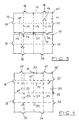
- Figure 1 shows a square foundation stone 1 with a Top 2 and four side faces 3. This cornerstone is in the rectangular stones shown in Figures 2 and 3 twice and in the square stone shown in Figure 4 included four times.
- Stone 1 is defined by two center lines (bisector) 4, 5 divided into a grid with four squares. These center lines 4, 5 form reference lines for the arrangement of spacers on the side surfaces, at which are protruding portions from the side surfaces that covers the entire height of the side surfaces or extend only over part of this height can.
- center lines 4, 5 form reference lines for the arrangement of spacers on the side surfaces, at which are protruding portions from the side surfaces that covers the entire height of the side surfaces or extend only over part of this height can.
- there are four spacers 6, 7, 8, 9 present in the form of teeth are designed with a flattened tip, i.e. two have sloping side surfaces and a flat end surface. The side surfaces are used for contact with the side surfaces the spacer from neighboring stones if the end faces are on the side faces of the neighboring Support stones.
- Two spacers 6, 7 or 8, 9 on two opposite Side surfaces form a pair of spacers.
- the spacers a pair are arranged so that they with respect to a connecting both sides Line are offset from each other.
- Both Spacers 6, 7, this reference line is the center line or bisector 4, while the reference line in the Spacers 8, 9 is formed by a line 10 that with respect to the corresponding center line or side bisector 5 shifted by a spacer width "b" is.
- FIG. 2 shows two paving stones 10 placed one against the other the top view. Both stones are identical and have a rectangular top 11 and four side surfaces, which consist of two long side surfaces 12 and two assemble short side surfaces 13.
- the spacers are designed accordingly as with the paving stone Figure 1. Each stone is made up of two square ones Foundation stones according to Figure 1 together. On the two opposite long side surfaces 12 are two spacers 17 and two spacers 18 are arranged. The short side surfaces 13 each have a spacer 19 or 20 on.
- the spacers are on opposite Side surfaces offset relative to reference lines again arranged.
- the reference line is a quarter of the surface of the stone Line 14, while this is on the pair of spacers that are on the short side surfaces is arranged with respect to the Spacers 19, 20 bisect the surface of the stone Line 15 (center line) is.
- the one on the left in the figure Spacer pair on the opposite long side surfaces, which consists of the spacers 17, 18 has as reference line, line 16, which is opposite the quartering Line 14 around the width "b" of a spacer to the corner is arranged offset.
- the paving stone is used to identify the two outer spacer 17 a mark in the form a projecting element 21 on the side surface between the two spacers. This mark serves as a laying aid.
- Figure 4 shows a paving stone 30 with a square Top 31 and four equally long side surfaces 32.
- This Stone is made up of four square foundation stones of Figure 1 together.
- Two opposite side faces have two pairs of spacers, each consisting of the Assemble spacers 35, 36 and 37, 38.
- the spacers 46, 47, 48, 49 have a broadened base here, of which the tooth-shaped spacer with flattened Tip runs out. Support when putting stones together the flat end faces of the spacers on the flat surfaces of the base, i.e. the end faces do not contact the side surfaces 42, 50. On this way becomes one compared to the embodiment of the figures 2 and 3 enlarged joint between adjacent stones reached.
- the position of the spacers corresponds to of the paving stone of Figures 2 and 3, also here again three reference lines play a role, namely once the bisector 44, a line quartering the surface 43 and one opposite the line 43 by a spacer width "b" offset line 45. There are two internal Spacers 47 and two external spacers 46 on the opposite long side surfaces 42.
- FIG. 6 shows a top view of three in a group of runners laid stones that correspond to the stones of Figures 2 and 3. It can be seen that the lower one shown in the figure Stone with its two outer spacers each a spacer of the lower side surface in the figure of the two stones above. At 21 is the marking for the so-called big "bracket" is shown.
- FIG. 7 shows three rectangular stones 10 from FIGS. 2 and 3, the stone on the right in the figure is perpendicular to the two left stones of the figure is arranged.
- the right stone grips the right stone with its two outer ones Spacers the two on the end faces of the left Spacers arranged stones, so that there is a corresponding Bracket effect results.
- At 21 is the so-called large "bracket" indicated.
- Figure 8 shows a plan view of three laid in the bandage Rectangular stones 10. The representation is not to scale. It can be seen that the type of installation shown here is the upper one transverse stone with its two spacers 50 a small “bracket” that forms the spacers 51 from embraces two stones. This little “bracket” is the large “bracket” indicated by the projection 21 across from.
- the lower left stone in FIG. 8 encompasses his 21 indicated large "bracket" the two spacers horizontally on the faces of two more in the figure arranged stones.
- Paving stone is created, the laying pattern as in Allows normal stones without teeth, but in the full composite.
Abstract
Description
Die vorliegende Erfindung betrifft einen Pflasterstein mit einer parallel zueinander verlaufenden Oberseite und Unterseite sowie vier rechtwinklig hierzu verlaufenden Seitenflächen, an denen seitlich vorstehende Abstandshalter angeordnet sind, die mit Abstandshaltern von benachbarten Pflastersteinen zur Ausbildung von Fugen in seitliche Anlage treten.The present invention relates to a paving stone a parallel top and bottom and four side surfaces running at right angles to it, on which laterally protruding spacers are arranged are with spacers from neighboring paving stones for the formation of joints in the lateral system to step.
Derartige Pflastersteine sind bekannt. Die an den Seitenflächen der Pflastersteine angeordneten seitlich vorstehenden Abstandshalter dienen dazu, beim Aneinandersetzen der Pflastersteine definierte Fugen vorzusehen, um eine Versickerung des Regenwassers zu ermöglichen. Hierbei ist es bekannt, die Abstandshalter so auszubilden bzw. so anzuordnen, daß beim Aneinandersetzen von benachbarten Steinen die Abstandshalter in seitliche Anlage miteinander treten, so daß sich ein Verzahnungseffekt ergibt, der das verlegte Pflaster entsprechend stabilisiert. Stirnseitig stützen sich die Abstandshalter dabei an den Seitenflächen der benachbarten Steine oder an ebenen Flächen von Abstandshaltern der benachbarten Steine ab. Auf diese Weise läßt sich - trotz des vorgesehenen Fugenraumes - ein Pflaster mit Verbundwirkung erstellen. Such paving stones are known. The on the side surfaces the paving stones arranged laterally protruding Spacers are used when placing the Paving stones to provide defined joints to prevent seepage of rainwater. Here it is known to design or arrange the spacers so that when neighboring stones are placed next to each other Place spacers in side contact with each other, see above that there is a gear effect that misplaced that Patches stabilized accordingly. Support on the face the spacers on the side surfaces of the neighboring ones Stones or on flat surfaces of spacers of the neighboring stones. In this way - despite the planned joint space - a plaster with Create compound effect.
Mit den meisten bekannten Pflastersteinen lassen sich jedoch - bedingt durch die Form und/oder Lage der Abstandshalter - nur ganz bestimmte Verlegemuster erstellen, so daß die Vielseitigkeit des Einsatzes von derartigen Verbundsteinen zu wünschen übrig läßt.Most known paving stones can be used however - due to the shape and / or location of the spacers - create only certain laying patterns, so the versatility of using such Composite stones left something to be desired.
Der vorliegenden Erfindung liegt die Aufgabe zugrunde, eine Pflasterstein der angegebenen Art zu schaffen, der bei großem Fugenraum im Verbund besonders viele Verlegemuster ermöglicht.The present invention has for its object a To create paving stone of the specified type, which at large joint space in the network especially many installation patterns enables.
Diese Aufgabe wird erfindungsgemäß bei einem Pflasterstein
der angegebenen Art dadurch gelöst, daß
Der hier verwendete Begriff "Pflasterstein" soll sowohl neben Pflastersteinen in der Form eines Würfels, Quaders auch solche in der Form einer Platte abdecken. Der Begriff ist somit umfassend zu interpretieren. Wesentlich ist, daß der Stein neben einer Oberseite und einer gegenüberliegenden Unterseite vier Seitenflächen besitzt, von denen sich jeweils zwei gegenüberliegen und miteinander rechte Winkel bilden.The term "paving stone" used here is intended to be used in addition to Cobblestones in the shape of a cube, cuboid too cover those in the form of a plate. The term is thus to be interpreted comprehensively. It is essential that the Stone next to a top and an opposite Underside has four side surfaces, each of which is two opposite and right angles with each other form.
Mit dem Begriff "Abstandshalterpaar" ist gemeint, daß sich auf zwei gegenüberliegenden Seitenflächen je ein Abstandshalter befindet, die einander zugeordnet sind und zusammen ein Abstandshalterpaar bilden.The term "pair of spacers" means that a spacer on two opposite side surfaces located that are associated with each other and together form a pair of spacers.
Bei der erfindungsgemäßen Lösung ist auf zwei gegenüberliegenden Seitenflächen mindestens ein Abstandshalterpaar angeordnet. Bei größeren Steinformaten sind dort zwei, drei oder mehr Abstandshalterpaare vorgesehen. Geht man beispielsweise von einem Grundstein mit einer quadratischen Oberseite aus, so hat dieser erfindungsgemäß je ein Abstandshalterpaar auf zwei gegenüberliegenden Seitenflächen. Ein Stein mit rechteckiger Oberseite, der sich aus zwei Grundsteinen zusammensetzt, hat beispielsweise auf den gegenüberliegenden langen Seitenflächen zwei Abstandshalterpaare, während auf den gegenüberliegenden kurzen Seitenflächen ein Abstandshalterpaar angeordnet ist. Ein Pflasterstein mit quadratischer Oberseite, der sich wiederum aus zwei derartigen Rechtecksteinen zusammensetzt, hat jeweils auf zwei gegenüberliegenden Seitenflächen zwei Abstandshalterpaare. Bei noch größeren Steinformaten nimmt die Anzahl der Abstandshalterpaare entsprechend zu.In the solution according to the invention, two are opposite Side surfaces arranged at least one pair of spacers. For larger stone formats there are two or three or more pairs of spacers are provided. For example, if you go from a cornerstone with a square According to the invention, this has a pair of spacers on two opposite sides. A stone with a rectangular top made up of two The foundation stones are put together, for example, on the opposite long side surfaces two pairs of spacers, while on the opposite short side faces a pair of spacers is arranged. A paving stone with a square top, which in turn is made up of put together two such rectangular stones, each two pairs of spacers on two opposite side surfaces. With even larger stone formats, the number increases of the spacer pairs accordingly.
Erfindungsgemäß sind die auf den gegenüberliegenden Seitenflächen angeordneten Abstandshalter eines Paares um eine Abstandshalterbreite versetzt zueinander angeordnet. Hierdurch können die Abstandshalter mit entsprechend angeordneten Abstandshaltern eines Nachbarsteines in seitliche Anlage treten, so daß sich ein entsprechender Verzahnungseffekt (Verbundwirkung) ergibt. According to the invention are on the opposite side surfaces arranged spacers of a pair by one Spacer width offset from each other. Hereby the spacers can be arranged accordingly Spacers of a neighboring stone in the side system occur, so that there is a corresponding gear effect (Compound effect) results.
Die Besonderheit des erfindungsgemäß ausgebildeten Pflastersteines besteht nunmehr darin, daß die Abstandshalterpaare eines Steines keine identische Lage in bezug auf einen Fixpunkt am Stein, beispielsweise dessen Mittelpunkt, dessen Mittellinien, Ecken etc., besitzen. So ist das erste Abstandshalterpaar in bezug auf eine den Stein schneidende Linie versetzt angeordnet. Bei dem quadratischen Grundstein handelt es sich hierbei vorzugsweise um die die Fläche des Steines halbierende Linie. Bei einem sich aus zwei quadratischen Grundsteinen zusammensetzenden Rechteckstein ist es vorzugsweise eine den Stein viertelnde Linie, was ebenfalls auf den sich aus zwei Rechtecksteinen zusammensetzenden quadratischen Stein zutrifft. Bei größeren Formaten ist es vorzugsweise eine den Stein in acht, sechzehn etc. Teile unterteilende Linie. Diese Linien können als Rasterlinien angesehen werden, die die Steine in einzelne Quadrate unterteilen, wobei der quadratische Grundstein vier Quadrate, der Rechteckstein acht Quadrate, der sich aus zwei Rechtecksteinen zusammensetzende quadratische Stein sechzehn Quadrate etc. aufweist.The peculiarity of the paving stone designed according to the invention is now that the spacer pairs of a stone no identical position with respect to a fixed point on the stone, for example its center, whose center lines, corners, etc. have. So that's the first one Spacer pair with respect to one cutting the stone Line staggered. With the square foundation stone this is preferably the area of the Stone's bisecting line. With one made up of two square ones It is cornerstone composing rectangular stone preferably a line quartering the stone, which is also on the two rectangular stones square stone applies. With larger formats it is preferably one in eight, sixteen, etc. parts of the stone dividing line. These lines can be used as grid lines are viewed that divide the stones into individual squares, where the square cornerstone is four squares, the rectangular stone eight squares, which is made up of two rectangular stones composite square stone sixteen Squares, etc.
Das zweite Abstandshalterpaar ist nunmehr nicht in einer dem ersten Abstandshalterpaar entsprechenden Lage angeordnet, sondern in bezug auf eine in bezug auf die den Stein schneidende Linie um eine Abstandshalterbreite verschobene Linie versetzt, vorzugsweise zur Steinecke hin. Durch diese Positionsverschiebung wird folgendes erreicht, das am besten anhand eines acht Rasterquadrate aufweisenden Rechtecksteines erläutert werden kann.The second pair of spacers is now not in one arranged the position corresponding to the first pair of spacers, but in relation to one in relation to the stone cutting line shifted by a spacer width Line offset, preferably towards the corner of the stone. Through this Position shift does the following, the best based on a square stone with eight grid squares can be explained.
Wie vorstehend bereits erwähnt, weist nämlich ein derartiger Rechteckstein auf seinen gegenüberliegenden langen Seitenflächen zwei Abstandshalterpaare auf. Ein Paar hiervon ist dabei vorzugsweise so angeordnet, daß seine Abstandshalter in bezug auf eine den Stein viertelnde Linie versetzt sind. Das andere Paar ist so angeordnet, daß seine Abstandshalter in bezug auf eine zu der den Stein viertelnden Linie vorzugsweise zur Steinecke hin um die Breite eines Abstandshalters verschobene Linie versetzt sind. Diese beiden Abstandshalter sind daher näher an der zugehörigen Steinecke angeordnet als die Abstandshalter des anderen Paares. Ferner sind beide Abstandshalterpaare so angeordnet, daß sich in bezug auf die Mittellinie des Steines zwei innenliegende Abstandshalter auf einer Seitenfläche und zwei außenliegende Abstandshalter auf der gegenüberliegenden Seitenfläche ergeben.As already mentioned above, this is namely the case Rectangular stone on its opposite long side surfaces two pairs of spacers. A couple of them is preferably arranged so that its spacers offset with respect to a line quartering the stone are. The other pair is arranged so that its Spacers in relation to one to the quarter of the stone Line preferably to the stone corner around the width of a spacer shifted line are offset. These two spacers are therefore closer to the associated one Steinecke arranged as the spacers of the other couple. Furthermore, both pairs of spacers are like this arranged that with respect to the center line of the Stone two internal spacers on one side and two outer spacers on the opposite Side surface result.
Durch die verschobene Lage des einen Abstandshalterpaares gegenüber dem anderen Abstandshalterpaar wird erreicht, daß ein Rechteckstein mit seiner langen Seitenfläche in zwei verschiedenen Lagen an den anderen Rechteckstein angelegt werden kann. In der Normallage (bei entsprechender Position in bezug auf den anderen Stein) treten die beiden innenliegenden Abstandshalter des einen Steines mit den beiden außenliegenden Abstandshaltern des anderen Steines in seitliche Anlage. Bei einer um 180° gedrehten Lage treten die beiden Abstandshalter mit der langen Seitenfläche des anzulegenden Steines wiederum mit den beiden Abstandshaltern des anderen Steines in seitlichen Kontakt, jedoch in diesem Falle liegen die beiden Abstandshalter des anzulegenden Steines nicht beide innerhalb der Abstandshalter des anderen Steines, sondern es liegt lediglich einer innerhalb, während der andere außerhalb liegt. Während sich somit im erstgenannten Fall ein sogenannter "Klammereffekt" ergibt, der zu einer Vollverbundwirkung führt, ergibt sich im zweiten Fall zwar auch eine formschlüssige Anlage der beiden Abstandshalter, jedoch hierbei nur so, daß eine Relativverschiebung zwischen beiden Steinen noch möglich ist, wenn keine weiteren Nachbarsteine vorhanden sind. Es wird somit bei dieser Art der Anlage ein "Halbverbund" erreicht.Due to the shifted position of one pair of spacers compared to the other pair of spacers, it is achieved that a rectangular stone with its long side in two different layers on the other rectangular stone can be. In the normal position (with the appropriate position in relation to the other stone) step the two inside Spacer of one stone with the two outer spacers of the other stone in lateral Investment. With a position rotated by 180 °, the two spacers with the long side surface of the to be created Steines again with the two spacers the other stone in side contact, but in this Trap are the two spacers of the to be created Do not stone both within the other's spacers Stone, but there is only one inside, while the other is outside. So while in the former case results in a so-called "bracket effect", which leads to a full composite effect results in the second Case also a positive fit of the two Spacers, but only so that a relative displacement between the two stones is still possible if there are no other neighboring stones. So it will achieved a "semi-composite" with this type of system.
Erfindungsgemäß gilt somit generell folgendes:The following therefore generally applies according to the invention:
Bei einem Stein, der jeweils nur ein Abstandshalterpaar auf zwei gegenüberliegenden Seitenflächen aufweist, ist die Bezugslinie, relativ zu der die Abstandshalter des einen Paares versetzt zueinander angeordnet sind, zu der Bezugslinie (Mittellinie, Halbierende), relativ zu der die Abstandshalter des anderen Paares versetzt zueinander angeordnet sind, um die Breite eines Abstandshalters verschoben. Bei größeren Steinformaten, bei denen auf den gegenüberliegenden Seitenflächen mindestens zwei Abstandshalterpaare angeordnet sind, ist zwischen den Bezugslinien von mindestens zwei Paaren ebenfalls eine derartige Verschiebung um eine Abstandshalterbreite vorhanden, und zwar derart, daß sich bei diesen zwei Paaren auf der einen Seitenfläche zwei innenliegende und auf der gegenüberliegenden Seitenfläche zwei außenliegende Abstandshalter ergeben. Auf diese Weise wird einerseits der gewünschte Klammereffekt beim Anlegen in der Normallage und der gewünschte Halbverbund beim Anlegen in einer um 180° gedrehten Lage erreicht.In the case of a stone, there is only one pair of spacers at a time has two opposite side faces, is the reference line, relative to that of the spacers of the one pair are offset from each other to the reference line (Center line, bisector), relative to that of the spacers of the other pair are staggered, shifted by the width of a spacer. For larger ones Stone formats where those on the opposite Side surfaces arranged at least two pairs of spacers is between the reference lines of at least two Also pair such a shift by a spacer width available, in such a way that at these two pairs on the one side two inside and two on the opposite side result in external spacers. That way on the one hand the desired bracket effect when creating in the Normal position and the desired semi-composite when creating in reached a position rotated by 180 °.
Der Rechteckstein ist vorzugsweise so ausgebildet, daß die Abstandshalter des auf den gegenüberliegenden kurzen Seitenflächen angeordneten Paares in bezug auf die Flächenhalbierende oder Mittellinie des Steines versetzt angeordnet sind.The rectangular stone is preferably designed so that the Spacers on the opposite short side faces arranged pair with respect to the bisector or staggered centerline of the stone are.
Hat der Stein eine quadratische Ober- und Unterseite und setzt sich aus vier quadratischen Grundsteinen zusammen, so daß insgesamt sechzehn Quadratraster gebildet werden, so sind immer auf zwei gegenüberliegenden Seitenflächen zwei Abstandshalterpaare angeordnet. Hiervon ist jeweils ein Paar in bezug auf eine die Fläche des Steines viertelnde Linie um eine Abstandshalterbreite versetzt angeordnet, während das andere Paar ebenfalls um eine Abstandshalterbreite versetzt zueinander angeordnet ist, jedoch um eine zu einer die Fläche viertelnden Linie zur Ecke hin um eine Abstandshalterbreite verschobene Linie. Auch hierbei ist die Anordnung so, daß sich zwei innenliegende Abstandshalter auf der einen Seitenfläche und zwei außenliegende Abstandshalter auf der gegenüberliegenden Seitenfläche ergeben. Der gewünschte Klammereffekt und der gewünschte Halbverbund sind somit auch hier gewährleistet.The stone has a square top and bottom and is made up of four square foundations, so that a total of sixteen square grids are formed, so are always two on two opposite sides Spacer pairs arranged. There is one of each Pair in relation to a quarter of the surface of the stone Line offset by a spacer width, while the other pair also by a spacer width is offset from one another, but by one to a line quartering the surface towards the corner by one Spacer width shifted line. Here too is the arrangement so that there are two internal spacers on one side surface and two external spacers result on the opposite side surface. The desired bracket effect and the desired semi-composite are therefore also guaranteed here.
Hat ein Pflasterstein ein solches Format, daß auf seinen gegenüberliegenden Seitenflächen drei Abstandshalterpaare angeordnet sind, so weisen von diesen drei Paaren vorzugsweise zwei Paare zwei innenliegende und zwei außenliegende Abstandshalter auf. Zwischen diesen beiden Paaren wird daher der gewünschte Klammereffekt erreicht.Has a paving stone of such a format that on his opposite pairs of spacers are arranged, preferably of these three pairs two pairs two inside and two outside Spacers on. Therefore, between these two pairs the desired bracket effect is achieved.
Mit der efindungsgemäßen Ausbildung und Positionierung der Abstandshalter läßt sich eine Vielzahl von Verlegemustern im Vollverbund und Halbverbund realisieren, beispielsweise Läuferverbände, Ellbogenverbände, Fischgrätverbände etc. Der erfindungsgemäß ausgebildete Pflasterstein zeichnet sich daher durch eine besonders vielseitige Verwendbarkeit aus.With the training and positioning of the invention Spacers can be a variety of laying patterns Realize in a full and half network, for example Runner bandages, elbow bandages, herringbone bandages etc. The paving stone designed according to the invention draws is therefore particularly versatile out.
Die Form der Abstandshalter ist für die erfindungsgemäße Lösung nicht kritisch. Wichtig ist lediglich, daß die Abstandshalter von aneinander gelegten Pflastersteinen so miteinander verzahnbar sind, daß sich ein Vollverbund erreichen läßt, d.h. die Abstandshalter müssen so geformt sein, daß sie in seitliche Anlage miteinander treten, d.h. formschlüssigen Kontakt haben. Bei einer speziellen Ausführungsform der Erfindung sind sie zahnförmig ausgebildet und weisen abgeflachte Spitzen auf. Hierbei treten die seitlichen Schrägflächen mit den Schrägflächen der Abstandshalter benachbarter Steine in Kontakt, während sich die abgeflachten Spitzen an den Seitenflächen benachbarter Abstandshalter abstützen. Bei einer weiteren bevorzugten Ausführungsform weisen die Abstandshalter eine erweiterte Basis auf, auf der sich der eigentliche Abstandshalter befindet, der in diesem Falle ebenfalls zahnförmig ausgebildet sein und eine abgeflachte Spitze aufweisen kann. Bei dieser Ausführungsform stützen sich die abgeflachten Spitzen der Abstandshalter von benachbarten Steinen auf den ebenen Flächen der Basis ab, d.h. nicht auf den Seitenflächen selbst.The shape of the spacers is for the invention Solution not critical. It is only important that the spacers of paving stones put together can be interlocked so that a full network can be achieved lets, i.e. the spacers must be shaped like this be in side contact with each other, i.e. have positive contact. In a special embodiment of the invention they are tooth-shaped and have flattened tips. Here the side kick Sloping surfaces with the sloping surfaces of the spacers adjacent stones in contact while the flattened Tips on the side surfaces of adjacent spacers support. In a further preferred embodiment the spacers have an expanded base, on which the actual spacer is located, the in this case also be tooth-shaped and may have a flattened tip. In this embodiment support the flattened tips of the spacers of neighboring stones on the flat surfaces the base, i.e. not on the side surfaces themselves.
Die erfindungsgemäße Lösung will mit so wenig Abstandshaltern wie möglich auskommen, um einen möglichst großen Fugenraum zu erhalten. Insofern besteht vorzugsweise ein Abstandshalterpaar nur aus je einem Abstandshalter auf einer Seitenfläche. Ausgeschlossen ist hierbei jedoch nicht, daß ein Abstandshalterpaar je zwei oder mehr Abstandshalter auf einer Seitenfläche aufweist, beispielsweise in der Form von zwei oder mehr Zähnen, die dann mit einem oder mehreren Abstandshaltern (Zähnen) auf der Seitenfläche des benachbarten Steines in Kontakt treten. Eine derartige Ausführungsform dürfte jedoch nur in Ausnahmefällen zum Einsatz kommen, wenn eine besonders große Verbundwirkung bzw. Stabilität gewünscht wird, da hierdurch Fugenraum entfällt.The solution according to the invention wants with so few spacers as possible to get as large a joint space as possible to obtain. In this respect, there is preferably a pair of spacers only from one spacer on one Side surface. However, it is not excluded that a pair of spacers each two or more spacers has a side surface, for example in the form of two or more teeth, then with one or more spacers (Teeth) on the side face of the neighboring one Get in touch with the stone. Such an embodiment should only be used in exceptional cases, if a particularly large bond effect or stability is desired since this eliminates the need for joint space.
Zur Erkennung der außenliegenden oder innenliegenden Abstandshalter einer Seitenfläche (Klammereffekt) weist der erfindungsgemäß ausgebildete Pflasterstein vorzugsweise eine Markierung auf, die beispielsweise als vorstehender Abschnitt auf der Seitenfläche ausgebildet sein kann.For recognizing the external or internal spacers one side surface (bracket effect) has the Paving stone designed according to the invention preferably a marker that, for example, as the preceding Section can be formed on the side surface.
Die Erfindung wird nachfolgend anhand von Ausführungsbeispielen in Verbindung mit der Zeichnung im einzelnen erläutert. Es zeigen:
Figur 1- eine Draufsicht auf eine Ausführungsform eines einen Grundstein bildenden Pflastersteines mit quadratischer Oberseite;
Figur 2- eine Draufsicht auf zwei Pflastersteine mit rechteckiger Oberseite im aneinandergesetzten Zustand;
Figur 3- eine Draufsicht auf die beiden Rechtecksteine
der Figur 2, wobei jedoch der in der Zeichnung
obere Stein um 180° gegenüber der Lage
in
Figur 2 verdreht dargestellt ist; - Figur 4
- eine Draufsicht auf einen Pflasterstein mit quadratischer Oberseite;
Figur 5- eine Draufsicht auf einen Pflasterstein mit
rechteckiger Oberfläche, der eine andere Art
von Abstandshaltern aufweist als die
Steine der Figuren 1 bis 4; Figur 6- eine Draufsicht auf drei rechteckige Pflastersteine im Läuferverband;
Figur 7- eine Draufsicht auf drei rechteckige Pflastersteine, wobei ein Pflasterstein mit seiner Längsachse rechtwinkling zu den anderen beiden Steinen angeordnet ist; und
Figur 8- eine Draufsicht auf vier im Verband verlegte Rechtecksteine.
- Figure 1
- a plan view of an embodiment of a paving stone forming a foundation stone with a square top;
- Figure 2
- a plan view of two paving stones with a rectangular top in the assembled state;
- Figure 3
- a plan view of the two rectangular stones of Figure 2, but the upper stone in the drawing is shown rotated by 180 ° relative to the position in Figure 2;
- Figure 4
- a plan view of a paving stone with a square top;
- Figure 5
- a plan view of a paving stone with a rectangular surface, which has a different type of spacers than the stones of Figures 1 to 4;
- Figure 6
- a plan view of three rectangular paving stones in the runner association;
- Figure 7
- a plan view of three rectangular paving stones, one of which is arranged at right angles to the other two stones with its longitudinal axis; and
- Figure 8
- a top view of four rectangular stones laid in the association.
Die in den Figuren dargestellten Pflastersteine bestehen aus Beton und sind im wesentlichen plattenförmig ausgebildet, wobei sie eine Oberseite und eine Unterseite und vier Seitenflächen besitzen, die miteinander rechte Winkel bilden. Die Steine besitzen daher in der Draufsicht entweder eine quadratische oder eine rechteckige Form.The paving stones shown in the figures exist made of concrete and are essentially plate-shaped, being a top and a bottom and four Have side surfaces that form right angles with each other. The stones therefore have either a top view a square or a rectangular shape.
Figur 1 zeigt einen quadratischen Grundstein 1 mit einer
Oberseite 2 und vier Seitenflächen 3. Dieser Grundstein ist
in den in den Figuren 2 und 3 gezeigten Rechtecksteinen
zweimal und in dem in Figur 4 gezeigten quadratischen Stein
viermal enthalten.Figure 1 shows a
Der Stein 1 wird durch zwei Mittellinien (Seitenhalbierende)
4, 5 in ein Raster mit vier Quadraten unterteilt.
Diese Mittellinien 4, 5 bilden Bezugslinien für die Anordnung
von Abstandshaltern auf den Seitenflächen, bei
denen es sich um von den Seitenflächen vorspringende Abschnitte
handelt, die sich über die gesamte Höhe der Seitenflächen
bzw. nur über einen Teil dieser Höhe erstrecken
können. Bei den Pflastersteinen der Figur 1 sind vier Abstandshalter
6, 7, 8, 9 vorhanden, die in der Form von Zähnen
mit abgeflachter Spitze ausgebildet sind, d.h. zwei
schräge Seitenflächen und eine ebene Stirnfläche besitzen.
Die Seitenflächen dienen hierbei zur Anlage mit den Seitenflächen
der Abstandshalter von benachbarten Steinen, wenn
die Stirnflächen sich an den Seitenflächen der benachbarten
Steine abstützen.
Zwei Abstandshalter 6, 7 oder 8, 9 auf zwei gegenüberliegenden
Seitenflächen bilden ein Abstandshalterpaar. Die Abstandshalter
eines Paares sind dabei so angeordnet, daß sie
in bezug auf eine beide Seitenflächen miteinander verbindende
Linie versetzt zueinander ausgebildet sind. Bei den
Abstandshaltern 6, 7 ist diese Bezugslinie die Mittellinie
oder Seitenhalbierende 4, während die Bezugslinie bei den
Abstandshaltern 8, 9 von einer Linie 10 gebildet wird, die
in bezug auf die entsprechende Mittellinie bzw. Seitenhalbierende
5 um eine Abstandshalterbreite "b" verschoben
ist.Two
Figur 2 zeigt zwei aneinandergesetzte Pflastersteine 10 in
der Draufsicht. Beide Steine sind identisch ausgebildet und
haben eine rechteckige Oberseite 11 sowie vier Seitenflächen,
die sich aus zwei langen Seitenflächen 12 und zwei
kurzen Seitenflächen 13 zusammensetzen. Die Abstandshalter
sind entsprechend ausgebildet wie bei dem Pflasterstein der
Figur 1. Jeder Stein setzt sich aus zwei quadratischen
Grundsteinen gemäß Figur 1 zusammen. Auf den beiden gegenüberliegenden
langen Seitenflächen 12 sind jeweils zwei Abstandshalter
17 und zwei Abstandshalter 18 angeordnet. Die
kurzen Seitenflächen 13 weisen je einen Abstandshalter 19
bzw. 20 auf.FIG. 2 shows two paving
Auch hier sind die Abstandshalter auf gegenüberliegenden
Seitenflächen wieder relativ zu Bezugslinien versetzt zueinander
angeordnet. Bei dem in Figur 2 rechten Abstandshalterpaar,
das aus den Abstandshaltern 17 und 18 besteht,
ist die Bezugslinie eine die Fläche des Steines viertelnde
Linie 14, während dies bei dem Abstandshalterpaar, das auf
den kurzen Seitenflächen angeordnet ist, in bezug auf die
Abstandshalter 19, 20 die die Fläche des Steines halbierende
Linie 15 (Mittellinie) ist. Das in der Figur linke
Abstandshalterpaar auf den gegenüberliegenden langen Seitenflächen,
das aus den Abstandshaltern 17, 18 besteht, hat
als Bezugslinie die Linie 16, die gegenüber der viertelnden
Linie 14 um die Breite "b" eines Abstandshalters zur Ecke
hin versetzt angeordnet ist. Es ergeben sich auf diese
Weise auf der in der Figur unteren langen Seitenfläche 12
zwei innenliegende Abstandshalter 18 und auf der in der Figur
oben liegenden Seitenfläche 12 zwei außenliegende Abstandshalter
17. Werden zwei Steine in der in Figur 2 gezeigten
Art aneinandergesetzt, so umklammern die beiden
außenliegenden Abstandshalter 17 des einen Steines die beiden
innenliegenden Abstandshalter 18 des anderen Steines,
so daß beide Steine in Querrichtung der Figur fixiert sind
und sich ein Vollverbund ergibt.Again, the spacers are on opposite
Side surfaces offset relative to reference lines again
arranged. In the pair of spacers on the right in FIG. 2,
which consists of the
Durch den Versatz des in Figur 2 links dargestellten Abstandshalterpaares
17, 18 gegenüber dem in der Figur rechts
dargestellten Abstandshalterpaar ist es möglich, den in Figur
2 oben dargestellten Stein nicht nur in der Stellung
gemäß Figur 2, sondern auch in der in Figur 3 gezeigten
Stellung an den unteren Stein anzulegen. Diese in Figur 3
gezeigte Stellung des oberen Steines ist gegenüber der von
Figur 2 um 180° gedreht. Man erkennt, daß in dieser Stellung
die beiden Abstandshalter 17 der in der Figur unteren
Seitenfläche des oberen Steines jetzt jeweils rechts von
den beiden Abstandshaltern 17 der oberen Seitenfläche des
unteren Steines liegen. In dieser Stellung ergibt sich zwar
ebenfalls eine Anlage der Schrägflächen der Abstandshalter,
jedoch lassen sich in dieser Stellung beide Steine in Querrichtung
relativ zueinander bewegen. Es wird somit nicht
der in Figur 2 erreichte Vollverbund, sondern lediglich ein
Halbverbund erreicht.By the offset of the pair of spacers shown on the left in FIG. 2
17, 18 compared to that in the figure on the right
spacer pair shown, it is possible to the in Figure
2 stone shown above not only in the position
according to Figure 2, but also in that shown in Figure 3
Position on the lower stone. This in Figure 3
shown position of the upper stone is opposite to that of
Figure 2 rotated by 180 °. You can see that in this position
the two
Bei der in den Figuren 2 und 3 dargestellten Ausführungsform
des Pflastersteines ist zur Kennzeichnung der beiden
außenliegenden Abstandshalter 17 eine Markierung in Form
eines vorspringenden Elementes 21 an der Seitenfläche zwischen
den beiden Abstandshaltern vorgesehen. Diese Markierung
dient als Verlegehilfe.In the embodiment shown in Figures 2 and 3
The paving stone is used to identify the two
outer spacer 17 a mark in the form
a projecting
Figur 4 zeigt einen Pflasterstein 30 mit quadratischer
Oberseite 31 und vier gleich langen Seitenflächen 32. Dieser
Stein setzt sich aus vier quadratischen Grundsteinen
der Figur 1 zusammen. Zwei gegenüberliegende Seitenflächen
besitzen zwei Abstandshalterpaare, die sich jeweils aus den
Abstandshaltern 35, 36 und 37, 38 zusammensetzen.Figure 4 shows a paving
Auch hier ist wiederum ein Abstandshalterpaar in bezug auf
die Steinecke gegenüber dem anderen versetzt angeordnet.
Während das in Figur 4 rechte Abstandshalterpaar 35, 36 relativ
zu einer die Fläche des Steines viertelnden Bezugslinie
33 versetzt angeordnet ist, ist das in der Figur 4
linke Abstandshalterpaar in bezug auf eine Linie 60 versetzt
angeordnet, die gegenüber der die Fläche viertelnde
Linie 33 um eine Abstandshalterbreite "b" zur Ecke hin verschoben
ist. Hierdurch ergeben sich die vorstehend in Verbindung
mit den Rechtecksteinen beschriebenen zwei verschiedenen
Anlagemöglichkeiten. Auch der Stein der Figur 4
hat eine Markierung 39 in Form eines vorspringenden Abschnittes,
der die beiden außenliegenden Abstandshalter 35
bzw. 37 kennzeichnet.Again, there is a pair of spacers with respect to
the stone corner is offset from the other.
While the pair of
Der in Figur 5 dargestellte Pflasterstein 40 mit rechteckiger
Oberseite 41 und zwei langen Seitenflächen 42 sowie
zwei kurzen Seitenflächen 50 ist, abgesehen von der Form
der Abstandshalter, entsprechend ausgebildet wie der in den
Figuren 2 und 3 dargestellte Rechteckstein. Die Abstandshalter
46, 47, 48, 49 besitzen hier eine verbreiterte Basis,
von der der zahnförmige Abstandshalter mit abgeflachter
Spitze ausgeht. Beim Aneinandersetzen von Steinen stützen
sich hierbei die ebenen Stirnflächen der Abstandshalter
an den ebenen Flächen der Basis ab, d.h. die Stirnflächen
treten nicht mit den Seitenflächen 42, 50 in Kontakt. Auf
diese Weise wird eine gegenüber der Ausführungsform der Figuren
2 und 3 vergrößerte Fuge zwischen benachbarten Steinen
erreicht. Die Lage der Abstandshalter entspricht der
des Pflastersteines der Figuren 2 und 3, wobei auch hier
wieder drei Bezugslinien eine Rolle spielen, nämlich einmal
die Flächenhalbierende 44, eine die Fläche viertelnde Linie
43 und eine gegenüber der Linie 43 um eine Abstandshalterbreite
"b" versetzte Linie 45. Es ergeben sich zwei innenliegende
Abstandshalter 47 und zwei außenliegende Abstandshalter
46 auf den gegenüberliegenden langen Seitenflächen
42.The paving
Figur 6 zeigt eine Draufsicht auf drei in Läuferverband verlegte Steine, die den Steinen der Figuren 2 und 3 entsprechen. Man erkennt, daß der in der Figur gezeigte untere Stein mit seinen beiden außenliegenden Abstandshaltern je einen Abstandshalter der in der Figur unteren Seitenfläche der beiden darüberliegenden Steine umklammert. Bei 21 ist die Markierung für die sogenannte große "Klammer" dargestellt.FIG. 6 shows a top view of three in a group of runners laid stones that correspond to the stones of Figures 2 and 3. It can be seen that the lower one shown in the figure Stone with its two outer spacers each a spacer of the lower side surface in the figure of the two stones above. At 21 is the marking for the so-called big "bracket" is shown.
Figur 7 zeigt drei Rechtecksteine 10 der Figuren 2 und 3,
wobei der in der Figur rechte Stein rechtwinklig zu den
beiden linken Steinen der Figur angeordnet ist. Auch hier
umgreift der rechte Stein mit seinen beiden außenliegenden
Abstandshaltern die beiden an den Stirnseiten der linken
Steine angeordneten Abstandshalter, so daß sich ein entsprechender
Klammereffekt ergibt. Bei 21 ist jeweils die
sogenannte große "Klammer" angedeutet.FIG. 7 shows three
Abschließend sei darauf hingewiesen, daß die in den Figuren 2 bis 7 dargestellten Pflastersteine in Bezug auf Ihre Abmessungen relativ zum quadratischen Stein der Figur 1 nicht maßstabsgetreu dargestellt sind. So sind die Seitenlängen des Steines der Figur 4 relativ zu den Seitenlängen des Steines der Figur 1 zu kurz dargestellt. In Wirklichkeit müßten sie um das Maß einer Fuge verlängert sein, so daß der Stein der Figur 1 viermal im Stein der Figur 4 plus Fuge enthalten ist. Bei den dargestellten Rechtecksteinen ist das Verhältnis Länge:Breite ebenfalls nicht korrekt dargestellt. Die Länge des Steines muß zweimal dem Seitenmaß des Steines der Figur 1 zuzüglich einer Fugenbreite entsprechen. Diese Abweichungen in der Darstellung wirken sich jedoch nicht auf die hier in Rede stehende Erfindung aus.In conclusion, it should be noted that the in the figures 2 to 7 paving stones shown in terms of their dimensions not relative to the square stone of Figure 1 are shown to scale. So are the side lengths of the stone of Figure 4 relative to the side lengths of the Stone of Figure 1 shown too short. In reality they would have to be extended by the size of a joint so that the stone of Figure 1 four times in the stone of Figure 4 plus Fugue is included. For the rectangular stones shown the length: width ratio is also incorrect shown. The length of the stone must be twice the side dimension of the stone of Figure 1 plus a joint width correspond. These deviations in the presentation are effective however, does not refer to the invention in question out.
Figur 8 zeigt eine Draufsicht auf drei im Verband verlegte
Rechtecksteine 10. Die Darstellung ist nicht maßstäblich.
Man erkennt, daß bei der hier gezeigten Verlegeart der obere
querliegende Stein mit seinen beiden Abstandshaltern 50
eine kleine "Klammer" bildet, die die Abstandshalter 51 von
zwei angelegten Steinen umgreift. Diese kleine "Klammer"
liegt der durch den Vorsprung 21 angedeuteten großen "Klammer"
gegenüber.Figure 8 shows a plan view of three laid in the
Der in Figur 8 linke untere Stein umgreift mit seiner bei 21 angedeuteten großen "Klammer" die beiden Abstandshalter an den Stirnseiten zweier weiterer in der Figur waagerecht angeordneter Steine.The lower left stone in FIG. 8 encompasses his 21 indicated large "bracket" the two spacers horizontally on the faces of two more in the figure arranged stones.
Es läßt sich somit zusammenfassen, daß erfindungsgemäß ein Pflasterstein geschaffen wird, der Verlegemuster wie bei normalen Steinen ohne Verzahnung zuläßt, jedoch im Vollverbund.It can thus be summarized that according to the invention Paving stone is created, the laying pattern as in Allows normal stones without teeth, but in the full composite.
Claims (9)
Priority Applications (3)
| Application Number | Priority Date | Filing Date | Title |
|---|---|---|---|
| AT99110732T ATE267917T1 (en) | 1999-06-04 | 1999-06-04 | PAVEMENT STONE |
| DE59909591T DE59909591D1 (en) | 1999-06-04 | 1999-06-04 | paving stone |
| EP99110732A EP1057935B1 (en) | 1999-06-04 | 1999-06-04 | Paving stone |
Applications Claiming Priority (1)
| Application Number | Priority Date | Filing Date | Title |
|---|---|---|---|
| EP99110732A EP1057935B1 (en) | 1999-06-04 | 1999-06-04 | Paving stone |
Publications (2)
| Publication Number | Publication Date |
|---|---|
| EP1057935A1 true EP1057935A1 (en) | 2000-12-06 |
| EP1057935B1 EP1057935B1 (en) | 2004-05-26 |
Family
ID=8238287
Family Applications (1)
| Application Number | Title | Priority Date | Filing Date |
|---|---|---|---|
| EP99110732A Expired - Lifetime EP1057935B1 (en) | 1999-06-04 | 1999-06-04 | Paving stone |
Country Status (3)
| Country | Link |
|---|---|
| EP (1) | EP1057935B1 (en) |
| AT (1) | ATE267917T1 (en) |
| DE (1) | DE59909591D1 (en) |
Cited By (2)
| Publication number | Priority date | Publication date | Assignee | Title |
|---|---|---|---|---|
| DE10323511B4 (en) * | 2003-05-24 | 2006-01-26 | Betonwerke Munderkingen Reinschütz GmbH | stone set |
| US7575392B2 (en) | 2001-10-05 | 2009-08-18 | Sf-Kooperation Gmbh Beton-Konzepte | Concrete-molded stone and ready-to-assemble construction made of molded stones |
Families Citing this family (1)
| Publication number | Priority date | Publication date | Assignee | Title |
|---|---|---|---|---|
| CN104746787B (en) * | 2015-03-07 | 2017-09-29 | 蒋景华 | A kind of brick with rock-steady structure |
Citations (3)
| Publication number | Priority date | Publication date | Assignee | Title |
|---|---|---|---|---|
| DE29516425U1 (en) * | 1994-11-23 | 1995-12-07 | Tschuemperlin Ag A | Rectangular composite stone |
| DE29721360U1 (en) * | 1997-12-03 | 1998-02-12 | Staats Manfred | Molded stone with spacers |
| WO1998030754A1 (en) * | 1997-01-08 | 1998-07-16 | Peter Geiger | Concrete material paving stone |
-
1999
- 1999-06-04 DE DE59909591T patent/DE59909591D1/en not_active Expired - Lifetime
- 1999-06-04 EP EP99110732A patent/EP1057935B1/en not_active Expired - Lifetime
- 1999-06-04 AT AT99110732T patent/ATE267917T1/en active
Patent Citations (3)
| Publication number | Priority date | Publication date | Assignee | Title |
|---|---|---|---|---|
| DE29516425U1 (en) * | 1994-11-23 | 1995-12-07 | Tschuemperlin Ag A | Rectangular composite stone |
| WO1998030754A1 (en) * | 1997-01-08 | 1998-07-16 | Peter Geiger | Concrete material paving stone |
| DE29721360U1 (en) * | 1997-12-03 | 1998-02-12 | Staats Manfred | Molded stone with spacers |
Cited By (2)
| Publication number | Priority date | Publication date | Assignee | Title |
|---|---|---|---|---|
| US7575392B2 (en) | 2001-10-05 | 2009-08-18 | Sf-Kooperation Gmbh Beton-Konzepte | Concrete-molded stone and ready-to-assemble construction made of molded stones |
| DE10323511B4 (en) * | 2003-05-24 | 2006-01-26 | Betonwerke Munderkingen Reinschütz GmbH | stone set |
Also Published As
| Publication number | Publication date |
|---|---|
| DE59909591D1 (en) | 2004-07-01 |
| ATE267917T1 (en) | 2004-06-15 |
| EP1057935B1 (en) | 2004-05-26 |
Similar Documents
| Publication | Publication Date | Title |
|---|---|---|
| EP0377460B1 (en) | Set of concrete paving blocks | |
| EP0063795B1 (en) | Paving element, paving unit of diverse paving elements and group of paving elements | |
| EP0791689A1 (en) | Artificial stone for reinforcing outdoor traffic areas | |
| DE3502793A1 (en) | PANEL ELEMENT TO LAY ON THE GROUND FLOOR OR SIMILAR SURFACE | |
| DE4232300A1 (en) | Concrete pavement slab with vertical side faces - has three or more corners in plan view with vertical corner edges, coupled by side faces | |
| EP1335069B1 (en) | Artificial stone for pavings | |
| DE2452475C2 (en) | Covering plate made of plate parts connected to one another by breakable webs, preferably for traffic areas | |
| EP1057935B1 (en) | Paving stone | |
| CH616973A5 (en) | Interlocking-stone set for forming a floor covering | |
| EP1088941A1 (en) | Gutter and gutter element therefor | |
| AT403389B (en) | PAVING STONE IN RECTANGULAR SHAPE | |
| EP0415093B1 (en) | Hexagonal respectively pentagonal stone | |
| DE3737620A1 (en) | Grass paving stones | |
| DE19726920C2 (en) | paving stone | |
| EP3830340B1 (en) | Paving having a connection system | |
| DE3834267A1 (en) | Paving stone for producing grassed surfaces on which it is possible to travel | |
| EP0668399A2 (en) | Slab shaped paving element made of concrete | |
| EP0954639B1 (en) | Moulded brick building set | |
| DE2551091B2 (en) | Assembly stone | |
| EP3387188B1 (en) | Cruciform paving stone | |
| WO1999037868A1 (en) | Shaped brick for erecting walls, especially dry walls | |
| DE19509479A1 (en) | Paving stones with interlocking edges | |
| DE19517662A1 (en) | Group of pavement slabs with peripheral toothing | |
| DE19705298A1 (en) | Molded stone kit | |
| DE4200335A1 (en) | COMPOSITE PAVING STONE |
Legal Events
| Date | Code | Title | Description |
|---|---|---|---|
| PUAI | Public reference made under article 153(3) epc to a published international application that has entered the european phase |
Free format text: ORIGINAL CODE: 0009012 |
|
| 17P | Request for examination filed |
Effective date: 19991222 |
|
| AK | Designated contracting states |
Kind code of ref document: A1 Designated state(s): AT BE DE NL |
|
| AX | Request for extension of the european patent |
Free format text: AL;LT;LV;MK;RO;SI |
|
| AKX | Designation fees paid |
Free format text: AT BE DE NL |
|
| 17Q | First examination report despatched |
Effective date: 20020730 |
|
| GRAP | Despatch of communication of intention to grant a patent |
Free format text: ORIGINAL CODE: EPIDOSNIGR1 |
|
| GRAS | Grant fee paid |
Free format text: ORIGINAL CODE: EPIDOSNIGR3 |
|
| GRAA | (expected) grant |
Free format text: ORIGINAL CODE: 0009210 |
|
| AK | Designated contracting states |
Kind code of ref document: B1 Designated state(s): AT BE DE NL |
|
| REF | Corresponds to: |
Ref document number: 59909591 Country of ref document: DE Date of ref document: 20040701 Kind code of ref document: P |
|
| PLBE | No opposition filed within time limit |
Free format text: ORIGINAL CODE: 0009261 |
|
| STAA | Information on the status of an ep patent application or granted ep patent |
Free format text: STATUS: NO OPPOSITION FILED WITHIN TIME LIMIT |
|
| 26N | No opposition filed |
Effective date: 20050301 |
|
| PGFP | Annual fee paid to national office [announced via postgrant information from national office to epo] |
Ref country code: NL Payment date: 20060630 Year of fee payment: 8 |
|
| PGFP | Annual fee paid to national office [announced via postgrant information from national office to epo] |
Ref country code: BE Payment date: 20060711 Year of fee payment: 8 |
|
| BERE | Be: lapsed |
Owner name: *INNOCON G.M.B.H. Effective date: 20070630 |
|
| NLV4 | Nl: lapsed or anulled due to non-payment of the annual fee |
Effective date: 20080101 |
|
| PG25 | Lapsed in a contracting state [announced via postgrant information from national office to epo] |
Ref country code: BE Free format text: LAPSE BECAUSE OF NON-PAYMENT OF DUE FEES Effective date: 20070630 |
|
| PG25 | Lapsed in a contracting state [announced via postgrant information from national office to epo] |
Ref country code: NL Free format text: LAPSE BECAUSE OF NON-PAYMENT OF DUE FEES Effective date: 20080101 |
|
| PGFP | Annual fee paid to national office [announced via postgrant information from national office to epo] |
Ref country code: DE Payment date: 20120809 Year of fee payment: 14 |
|
| REG | Reference to a national code |
Ref country code: DE Ref legal event code: R119 Ref document number: 59909591 Country of ref document: DE Effective date: 20140101 |
|
| PG25 | Lapsed in a contracting state [announced via postgrant information from national office to epo] |
Ref country code: DE Free format text: LAPSE BECAUSE OF NON-PAYMENT OF DUE FEES Effective date: 20140101 |
|
| PGFP | Annual fee paid to national office [announced via postgrant information from national office to epo] |
Ref country code: AT Payment date: 20180627 Year of fee payment: 20 |
|
| REG | Reference to a national code |
Ref country code: AT Ref legal event code: MK07 Ref document number: 267917 Country of ref document: AT Kind code of ref document: T Effective date: 20190604 |