EP0668399A2 - Slab shaped paving element made of concrete - Google Patents
Slab shaped paving element made of concrete Download PDFInfo
- Publication number
- EP0668399A2 EP0668399A2 EP95102233A EP95102233A EP0668399A2 EP 0668399 A2 EP0668399 A2 EP 0668399A2 EP 95102233 A EP95102233 A EP 95102233A EP 95102233 A EP95102233 A EP 95102233A EP 0668399 A2 EP0668399 A2 EP 0668399A2
- Authority
- EP
- European Patent Office
- Prior art keywords
- side surfaces
- recesses
- sections
- paving
- paving stone
- Prior art date
- Legal status (The legal status is an assumption and is not a legal conclusion. Google has not performed a legal analysis and makes no representation as to the accuracy of the status listed.)
- Granted
Links
Images

Classifications
-
- E—FIXED CONSTRUCTIONS
- E01—CONSTRUCTION OF ROADS, RAILWAYS, OR BRIDGES
- E01C—CONSTRUCTION OF, OR SURFACES FOR, ROADS, SPORTS GROUNDS, OR THE LIKE; MACHINES OR AUXILIARY TOOLS FOR CONSTRUCTION OR REPAIR
- E01C5/00—Pavings made of prefabricated single units
- E01C5/06—Pavings made of prefabricated single units made of units with cement or like binders
-
- E—FIXED CONSTRUCTIONS
- E01—CONSTRUCTION OF ROADS, RAILWAYS, OR BRIDGES
- E01C—CONSTRUCTION OF, OR SURFACES FOR, ROADS, SPORTS GROUNDS, OR THE LIKE; MACHINES OR AUXILIARY TOOLS FOR CONSTRUCTION OR REPAIR
- E01C9/00—Special pavings; Pavings for special parts of roads or airfields
- E01C9/004—Pavings specially adapted for allowing vegetation
-
- Y—GENERAL TAGGING OF NEW TECHNOLOGICAL DEVELOPMENTS; GENERAL TAGGING OF CROSS-SECTIONAL TECHNOLOGIES SPANNING OVER SEVERAL SECTIONS OF THE IPC; TECHNICAL SUBJECTS COVERED BY FORMER USPC CROSS-REFERENCE ART COLLECTIONS [XRACs] AND DIGESTS
- Y02—TECHNOLOGIES OR APPLICATIONS FOR MITIGATION OR ADAPTATION AGAINST CLIMATE CHANGE
- Y02A—TECHNOLOGIES FOR ADAPTATION TO CLIMATE CHANGE
- Y02A30/00—Adapting or protecting infrastructure or their operation
- Y02A30/60—Planning or developing urban green infrastructure
Definitions
- the invention relates to a plate-shaped paving stone made of concrete material with a flat surface and lateral surfaces extending transversely to the surface.
- Cross-sectionally H-shaped paving stones are known.
- the known paving stones of this type are designed as solid stones. Due to their interlocking within the laying pattern, they have a high degree of cohesion, but as a disadvantage only a small area of application.
- this is achieved in that symmetrical, essentially trapezoidal recesses are formed in cross-section in two opposite side surfaces of the paving stone, the recesses on both sides of the inclined surfaces are limited by sections extending to the corner regions, that the recesses and the sections having side faces with a shorter length than the transverse side faces are formed and that a hole is formed centrally between the head sides of the trapezoidal recesses at a distance from the recesses and at a distance from the transverse side faces.
- the side surfaces having the indentations and the sections are formed with a length of essentially 198 mm and the side surfaces extending transversely thereto with a width of essentially 219 mm.
- a paving stone is created, which can be interlocked in the laying pattern with neighboring paving stones, due to its dimensional design, a high load-bearing capacity for laying that can be driven on, and through the formation of the perforation and filling of the same with any materials, e.g. Humus earth, vegetation areas or different effects are allowed to form.
- the larger width of the paving stone compared to the length of the paving stone ensures sufficiently large perforations and stable boundary surfaces.
- the perforation is provided with a square or rectangular cross-sectional shape and is formed parallel to the side surfaces having the recesses and the sections with a length of essentially 110 mm and transversely thereto with a width of essentially 88 mm.
- the corner areas of the perforations can be created by right-angled delimiting surfaces or appropriately by arched, e.g. arcuate sections may be limited.
- any combination of paving stones designed as solid or perforated stone according to the invention makes it possible to adapt the laying surface to the expected loads or to achieve effects by greening the perforations.
- the paving stone be designed as a half-stone with a separating surface extending in the area of the recesses over half its length.
- the paving stone 1 shown in Fig. 1 is designed as a shaped concrete block.
- the paving stone 1 has trapezoidal indentations 3, which are delimited on their inclined surfaces 3 ′′ by sections 4.
- the side surfaces 2 are connected to transversely extending side surfaces 8, the side surfaces 2 and 8 being designed as flat surfaces
- the side surfaces 2 which have the recesses 3 and sections 4 are of a shorter length than the side surfaces 8 which extend transversely thereto and are centered at a distance from the head sides 3 ′ of the recesses 3 and from the side surfaces 8 1 in the exemplary embodiment, for example rectangular perforation 5, which is delimited in the corner regions by circular-arc-shaped sections 5 '.
- the perforation 5 is selected in cross section in such a way that edge strips 6 of approximately the same width are formed all around, which ensure the load-bearing capacity of the paving stone.
- the perforation 5 is formed with a length of essentially 110 mm and a width of 88 mm. When laying the paving stone 1, it allows filling with any material, such as sand or humus, which can be planted in this way.
- the side surfaces 2 having the indentations 3 and the sections 4 are formed with a length of 198 mm and the side surfaces 8 extending transversely thereto with a width of essentially 219 mm.
- adjacent paving stones 1 engage with their sections 4 in the recesses 3 in the laying pattern and thereby result in a toothing which ensures firm cohesion of the paving stones 1 in the laying pattern.
- paving stones 1 provided with perforations 5 are joined together with paving stones 1 ′′ formed as solid stones, the external dimensions of both types of paving stones being the same.
- half stones 1 ' which are expediently designed as full stones and have their separating surface in the central region of the recesses.
- a large number of paving stones 1 and paving stones 1 "provided with perforations are joined together to form a laying pattern without perforations.
- the laying of the paving stones 1. 1" can be done by machine.
- the laying is preferably done as track-waystones, e.g. for land consolidation.
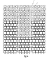
- paving stones 1 "are laid with paving stones 7 of known design. It can be seen that with the same lengths of paving stones 1" and 7 over a width of seven known paving stones 7, a seamless connection of five paving stones 1 "or 1 is possible.
Abstract
Description
Die Erfindung betrifft einen plattenförmigen Pflasterstein aus Betonwerkstoff mit einer ebenen Oberfläche und quer zur Oberfläche sich erstrekkenden Seitenflächen.The invention relates to a plate-shaped paving stone made of concrete material with a flat surface and lateral surfaces extending transversely to the surface.
Es sind im Querschnitt H-förmige Pflastersteine bekannt. Die bekannten Pflastersteine dieser Art sind als Vollsteine ausgeführt. Sie weisen durch ihre Verzahnung innerhalb des Verlegemusters ein großes Zusammenhaltsvermögen, jedoch als Nachteil nur einen geringen Anwendungsbereich auf.Cross-sectionally H-shaped paving stones are known. The known paving stones of this type are designed as solid stones. Due to their interlocking within the laying pattern, they have a high degree of cohesion, but as a disadvantage only a small area of application.
Es ist Aufgabe der Erfindung unter Beibehaltung des Zusammenhaltsvermögens Maßnahmen zur Vergößerung des Anwendungsbereichs bei Pflastersteinen dieser Art zu schaffen.It is an object of the invention to provide measures for increasing the area of application for paving stones of this type while maintaining the cohesiveness.
Gemäß der Erfindung wird dies dadurch erreicht, daß in zwei einander gegenüberliegenden Seitenflächen des Pflastersteins im Querschnitt symmetrische, im wesentlichen trapezförmige Einziehungen ausgebildet sind, die Einziehungen beidseitig der Schrägflächen durch bis zu den Eckbereichen sich erstreckende Abschnitte begrenzt sind, daß die die Einziehungen und die Abschnitte aufweisenden Seitenflächen mit einer geringeren Länge als die quer dazu sich erstreckenden Steitenflächen ausgebildet sind und daß mittig zwischen den Kopfseiten der trapezförmigen Einziehungen mit Abstand zu den Einziehungen und mit Abstand zu den quer sich erstreckenden Seitenflächen eine Lochung ausgeformt ist.According to the invention, this is achieved in that symmetrical, essentially trapezoidal recesses are formed in cross-section in two opposite side surfaces of the paving stone, the recesses on both sides of the inclined surfaces are limited by sections extending to the corner regions, that the recesses and the sections having side faces with a shorter length than the transverse side faces are formed and that a hole is formed centrally between the head sides of the trapezoidal recesses at a distance from the recesses and at a distance from the transverse side faces.
Gemäß bevorzugter Ausführung sind die die Einziehungen und die Abschnitte aufweisenden Seitenflächen mit einer Länge von im wesentlichen 198 mm und die quer dazu sich erstreckenden Seitenflächen mit einer Breite von im wesentlichen 219 mm ausgebildet. Auf diese Weise ist ein Pflasterstein geschaffen, der im Verlegemuster mit benachbarten Pflastersteinen verzahnbar ist, durch seine maßliche Ausgestaltung eine hohe Tragfähigkeit zu befahrbaren Verlegungen und durch die Ausbildung der Lochung und Auffüllen derselben mit beliebigen Materialien, z.B. Humuserde, Bewuchsflächen bzw. unterschiedliche Effekte zu bilden erlaubt. Die gegenüber der Länge des Pflastersteins größer gewählte Breite desselben sichert dabei ausreichend große Lochungen und stabile Begrenzungsflächen zu.According to a preferred embodiment, the side surfaces having the indentations and the sections are formed with a length of essentially 198 mm and the side surfaces extending transversely thereto with a width of essentially 219 mm. In this way, a paving stone is created, which can be interlocked in the laying pattern with neighboring paving stones, due to its dimensional design, a high load-bearing capacity for laying that can be driven on, and through the formation of the perforation and filling of the same with any materials, e.g. Humus earth, vegetation areas or different effects are allowed to form. The larger width of the paving stone compared to the length of the paving stone ensures sufficiently large perforations and stable boundary surfaces.
In Ausgestaltung des Pflastersteins ist die Lochung mit einer quadratischen oder rechteckförmigen Querschnittsform vorgesehen und parallel zu den die Einziehungen und die Abschnitte aufweisenden Seitenflächen mit einer Länge von im wesentlichen 110 mm und quer dazu mit einer Breite von im wesentlichen 88 mm ausgebildet. Die Eckbereiche der Lochungen können dabei durch rechtwinklig zusammenstoßende Begrenzungsflächen oder zweckmäßig durch bogenförmige, z.B. kreisbogenförmige Abschnitte begrenzt sein.In the embodiment of the paving stone, the perforation is provided with a square or rectangular cross-sectional shape and is formed parallel to the side surfaces having the recesses and the sections with a length of essentially 110 mm and transversely thereto with a width of essentially 88 mm. The corner areas of the perforations can be created by right-angled delimiting surfaces or appropriately by arched, e.g. arcuate sections may be limited.
Außerdem ist vorgesehen, in zwei einander gegenüberliegenden Seitenflächen im Querschnitt symmetrische trapezförmige Einziehungen und diese begrenzende Abschnitte anzuordnen, die Seitenflächen mit einer geringeren Länge als die quer dazu sich erstreckenden Seitenflächen Zu versehen und den Pflasterstein als Vollstein auszubilden. Durch beliebig wählbare Kombinationen von als Vollstein oder Lochstein ausgebildeten Pflastersteine gemäß der Erfindung, ist die Möglichkeit gegeben, die Verlegefläche den zu erwartenden Belastungen anzupassen bzw. durch Begrünen der Lochungen Effekte zu erreichen. Fernerhin ist vorgesehen, den Pflasterstein als Halbstein mit im Bereich der Einziehungen auf halber Länge derselben sich erstreckende Trennungsfläche auszubilden. Vermittels der Halbsteine können die, z.B. bei im Läuferverband verlegten Pflastersteinen die verbleibenden Öffnungen in den Endbereichen unter Beibehaltung des Verlegemusters geschlossen werden.In addition, it is provided to arrange symmetrical trapezoidal indentations and sections delimiting them in two opposite side surfaces, to provide the side surfaces with a shorter length than the side surfaces extending transversely thereto and to form the paving stone as a solid stone. Any combination of paving stones designed as solid or perforated stone according to the invention makes it possible to adapt the laying surface to the expected loads or to achieve effects by greening the perforations. Furthermore, it is provided that the paving stone be designed as a half-stone with a separating surface extending in the area of the recesses over half its length. By means of the half stones, e.g. in the case of paving stones laid in the runner bandage, the remaining openings in the end regions are closed while maintaining the laying pattern.
Schließlich ist noch vorgesehen, mehrere Pflastersteine gemeinsam mit Einziehungen und diese begrenzenden Abschnitte aufweisenden Pflastersteinen, deren die Einziehungen und Abschnitte aufweisenden Seitenflächen gleiche Längen jedoch quer dazu mit geringeren Breiten aufweisenden Seitenflächen versehen sind zu einem Verlegemuster im Breitenverhältnis 5:7 zusammen zu fügen.Finally, it is also planned to join together a number of paving stones together with recesses and paving stones which have these delimiting sections, the side surfaces of the recesses and sections having the same lengths but transverse to them having smaller widths, to form a laying pattern in a width ratio of 5: 7.
Wie die Erfindung ausgeführt sein kann, zeigt mit den für diese wesentlichen Merkmalen das in den Zeichnungen dargestellte Ausführungsbeispiel. Es zeigen:
- Fig. 1 einen Pflasterstein in Draufsicht,
- Fig. 2 mehrere als Vollsteine und Lochsteine ausgebildete Pflastersteine zu einem Verlegemuster zusammengefügt, in Draufsicht,
- Fig. 3 mehrere mit Pflastersteinen bekannter Ausführung zu einem Verlegemuster zusammengefügte Pflastersteine in Draufsicht und
- Fig. 4 ein Verlegemuster mit Pflastersteinen, verkleinert, in Draufsicht.
- 1 is a paving stone in plan view,
- 2 shows a number of paving stones designed as solid stones and perforated stones, in plan view,
- Fig. 3 several paving stones of known design assembled into a laying pattern paving stones in plan view and
- Fig. 4 is a laying pattern with paving stones, reduced, in plan view.
Der in Fig. 1 gezeigte Pflasterstein 1 ist als Betonformstein ausgeführt. In zwei einander gegenüberliegenden Seitenflächen 2 weist der Pflasterstein 1 trapezförmige Einziehungen 3 auf, die an ihren Schrägflächen 3" durch Abschnitte 4 begrenzt sind. Die Seitenflächen 2 stehen mit quer erstreckenden Seitenflächen 8 in Verbindung, wobei die Seitenflächen 2 und 8 als ebene Flächen ausgeführt sind. Die die Einziehungen 3 und Abschnitte 4 aufweisenden Seitenflächen 2 sind mit einer geringeren Länge ausgeführt als die quer dazu sich erstreckenden Seitenflächen 8. Mittig im Abstand zu den Kopfseiten 3' der Einziehungen 3 und zu den Seitenflächen 8 weist der Pflasterstein 1 eine beim Ausführungsbeispiel, z.B. rechteckförmige Lochung 5 auf, die in den Eckbereichen durch kreisbogenförmige Abschnitte 5' begrenzt ist. Die Lochung 5 ist beim Ausführungsbeispiel im Querschnitt so gewählt, daß umlaufend etwa gleichbreite Randstreifen 6 gebildet sind, die die Tragfähigkeit des Pflastersteins sichern. Die Lochung 5 ist mit einer Länge von im wesentlichen 110 mm und einer Breite von 88 mm ausgebildet. Sie erlaubt beim Verlegen des Pflastersteins 1 ein Auffüllen mit beliebigen Materialien, z.B. Sand oder Humuserde, die kann so begrünt werden. Die die Einziehungen 3 und die Abschnitte 4 aufweisenden Seitenflächen 2 sind mit einer Länge von 198 mm und die quer dazu sich erstreckenden Seitenflächen 8 mit einer Breite von im wesentlichen 219 mm ausgebildet.The
Wie die Fig. 2 erkennen läßt, greifen im Verlegemuster benachbarte Pflastersteine 1 mit ihren Abschnitten 4 in die Einziehungen 3 ein und ergeben dadurch eine Verzahnung, die einen festen Zusammenhalt der Pflastersteine 1 im Verlegemuster gewährleistet.As can be seen in FIG. 2,
Beim Ausführungsbeispiel der Fig. 2 sind weiter mit Lochungen 5 versehene Pflastersteine 1 mit als Vollsteine ausgebildeten Pflastersteinen 1" zusammengefügt, wobei die Außenabmessungen beider Pflastersteinsorten gleich sind.In the exemplary embodiment in FIG. 2, paving
Die verbleibenden Abstände beim Verlegen der Pflastersteine 1 im Bereich der Enden können durch Halbsteine 1' geschlossen werden, die zweckmäßig als Vollsteine ausgeführt sind und im Mittelbereich der Einziehungen ihre Trennungsfläche aufweisen.The remaining distances when laying the
Beim Ausführungsbeispiel der Fig. 4 sind eine Vielzahl mit Lochungen versehene Pflastersteine 1 und Pflastersteine 1" ohne Lochungen zu einem Verlegemuster zusammengefügt. Die Verlegung der Pflastersteine 1,1" kann maschinell erfolgen. Die Verlegung erfolgt bevorzugt als Spur-Wegsteine, z.B. bei Flurbereinigungen.4, a large number of
In Fig. 3 sind Pflastersteine 1" mit Pflastersteinen 7 bekannter Ausführung verlegt. Es zeigt sich, daß bei gleichen Längen der Pflastersteine 1" und 7 auf einer Breite von sieben bekannten Pflastersteinen 7 ein lückenloser Anschluß von fünf Pflastersteinen 1" oder 1 möglich ist.In Fig. 3 paving
Claims (7)
Applications Claiming Priority (2)
| Application Number | Priority Date | Filing Date | Title |
|---|---|---|---|
| DE4405535 | 1994-02-22 | ||
| DE4405535A DE4405535A1 (en) | 1994-02-22 | 1994-02-22 | Slab-shaped paving stone made of concrete material |
Publications (3)
| Publication Number | Publication Date |
|---|---|
| EP0668399A2 true EP0668399A2 (en) | 1995-08-23 |
| EP0668399A3 EP0668399A3 (en) | 1996-01-24 |
| EP0668399B1 EP0668399B1 (en) | 2002-11-13 |
Family
ID=6510801
Family Applications (1)
| Application Number | Title | Priority Date | Filing Date |
|---|---|---|---|
| EP95102233A Expired - Lifetime EP0668399B1 (en) | 1994-02-22 | 1995-02-17 | Slab shaped paving element made of concrete |
Country Status (4)
| Country | Link |
|---|---|
| EP (1) | EP0668399B1 (en) |
| AT (1) | ATE227792T1 (en) |
| DE (2) | DE4405535A1 (en) |
| ES (1) | ES2187536T3 (en) |
Cited By (1)
| Publication number | Priority date | Publication date | Assignee | Title |
|---|---|---|---|---|
| AT1087U1 (en) * | 1995-06-19 | 1996-10-25 | Hochmayer Heimo | PLANTABLE PAVING STONE |
Families Citing this family (3)
| Publication number | Priority date | Publication date | Assignee | Title |
|---|---|---|---|---|
| DE29517411U1 (en) * | 1995-11-03 | 1996-01-18 | Aicheler & Braun Gmbh | Hollow form stone |
| DE19705625A1 (en) * | 1997-02-14 | 1998-08-20 | Metten Stein & Design Gmbh | Paved area with rainwater drainage |
| DE10246115A1 (en) * | 2002-10-02 | 2004-04-22 | Joachim Falkenhagen | Road paving stone, to mark the division between traffic lanes, has a recessed center to be filled with earth and the like to cultivate vegetation |
Citations (4)
| Publication number | Priority date | Publication date | Assignee | Title |
|---|---|---|---|---|
| DE7308326U (en) * | 1973-06-07 | 1973-06-07 | Haffke P | |
| EP0015426A1 (en) * | 1979-02-15 | 1980-09-17 | Dr. Barth GmbH | Ground covering element with elevated areas on the top side separated by dummy gaps, group of such ground covering elements and process for manufacturing such elements |
| EP0212036A1 (en) * | 1985-08-19 | 1987-03-04 | Rolf Scheiwiller | Interconnecting stone for lawn |
| DE4112819A1 (en) * | 1991-04-19 | 1992-10-22 | Betonwerk Godelmann Kg | Paving system - has profiled stones indented on two opposite sides, which are laid in rows to half bond, and others recessed for grass laid at right angles |
-
1994
- 1994-02-22 DE DE4405535A patent/DE4405535A1/en not_active Withdrawn
-
1995
- 1995-02-17 DE DE59510447T patent/DE59510447D1/en not_active Expired - Lifetime
- 1995-02-17 AT AT95102233T patent/ATE227792T1/en not_active IP Right Cessation
- 1995-02-17 ES ES95102233T patent/ES2187536T3/en not_active Expired - Lifetime
- 1995-02-17 EP EP95102233A patent/EP0668399B1/en not_active Expired - Lifetime
Patent Citations (4)
| Publication number | Priority date | Publication date | Assignee | Title |
|---|---|---|---|---|
| DE7308326U (en) * | 1973-06-07 | 1973-06-07 | Haffke P | |
| EP0015426A1 (en) * | 1979-02-15 | 1980-09-17 | Dr. Barth GmbH | Ground covering element with elevated areas on the top side separated by dummy gaps, group of such ground covering elements and process for manufacturing such elements |
| EP0212036A1 (en) * | 1985-08-19 | 1987-03-04 | Rolf Scheiwiller | Interconnecting stone for lawn |
| DE4112819A1 (en) * | 1991-04-19 | 1992-10-22 | Betonwerk Godelmann Kg | Paving system - has profiled stones indented on two opposite sides, which are laid in rows to half bond, and others recessed for grass laid at right angles |
Cited By (1)
| Publication number | Priority date | Publication date | Assignee | Title |
|---|---|---|---|---|
| AT1087U1 (en) * | 1995-06-19 | 1996-10-25 | Hochmayer Heimo | PLANTABLE PAVING STONE |
Also Published As
| Publication number | Publication date |
|---|---|
| ES2187536T3 (en) | 2003-06-16 |
| EP0668399A3 (en) | 1996-01-24 |
| ATE227792T1 (en) | 2002-11-15 |
| DE59510447D1 (en) | 2002-12-19 |
| EP0668399B1 (en) | 2002-11-13 |
| DE4405535A1 (en) | 1995-08-24 |
Similar Documents
| Publication | Publication Date | Title |
|---|---|---|
| EP0465536B1 (en) | Angled paving stone | |
| EP0063795B1 (en) | Paving element, paving unit of diverse paving elements and group of paving elements | |
| EP0377460B1 (en) | Set of concrete paving blocks | |
| EP0657583B1 (en) | Plate-like paving stone particularly of concrete | |
| DE4405616A1 (en) | Paving stone with lateral spacers | |
| EP0170113A1 (en) | Building block | |
| EP0428762B1 (en) | Slab-shaped paving element | |
| DE19520887A1 (en) | Cobblestone arrangement with variable pattern | |
| EP0671508B1 (en) | Pavement | |
| EP2092121A1 (en) | Grass paver | |
| EP1088941B1 (en) | Gutter and gutter element therefor | |
| EP0668399A2 (en) | Slab shaped paving element made of concrete | |
| EP1024226B1 (en) | Artificial stone for pavings | |
| DE2452475A1 (en) | Highway paving slab module - interlocking briquettes connection ruptured during compaction etc. | |
| DE3320034A1 (en) | COMPONENT FOR PRODUCING A CARRIER OR THE LIKE | |
| DE4221900A1 (en) | Artificial-stone road-surface component - has side protrusions forming gaps with adjacent components and groove in bottom connecting gaps together | |
| AT403389B (en) | PAVING STONE IN RECTANGULAR SHAPE | |
| DE3703368A1 (en) | Prefabricated interlocking block | |
| DE7538657U (en) | ASSOCIATION | |
| DE3737620A1 (en) | Grass paving stones | |
| DE2225027A1 (en) | MOLDED CONCRETE BLOCK WITH SEVERAL VERTICAL OPENINGS AND POLYGONAL LIMITATION FOR SURFACE FASTENING OF TERRAIN | |
| DE3112608A1 (en) | Interlocking paving stone | |
| DE3510914A1 (en) | Double block | |
| DE3148779C2 (en) | Shaped stone dressing, especially for paving paths | |
| DE2836980A1 (en) | Versatile concrete paving stone - comprises two equal width shanks in angled plan shape to make interlocking pattern |
Legal Events
| Date | Code | Title | Description |
|---|---|---|---|
| PUAI | Public reference made under article 153(3) epc to a published international application that has entered the european phase |
Free format text: ORIGINAL CODE: 0009012 |
|
| AK | Designated contracting states |
Kind code of ref document: A2 Designated state(s): AT BE CH DE ES FR GB IT LI NL |
|
| PUAL | Search report despatched |
Free format text: ORIGINAL CODE: 0009013 |
|
| AK | Designated contracting states |
Kind code of ref document: A3 Designated state(s): AT BE CH DE ES FR GB IT LI NL |
|
| 17P | Request for examination filed |
Effective date: 19960722 |
|
| 17Q | First examination report despatched |
Effective date: 20000502 |
|
| GRAG | Despatch of communication of intention to grant |
Free format text: ORIGINAL CODE: EPIDOS AGRA |
|
| GRAG | Despatch of communication of intention to grant |
Free format text: ORIGINAL CODE: EPIDOS AGRA |
|
| GRAH | Despatch of communication of intention to grant a patent |
Free format text: ORIGINAL CODE: EPIDOS IGRA |
|
| GRAH | Despatch of communication of intention to grant a patent |
Free format text: ORIGINAL CODE: EPIDOS IGRA |
|
| 19U | Interruption of proceedings before grant |
Effective date: 20020325 |
|
| 19W | Proceedings resumed before grant after interruption of proceedings |
Effective date: 20020615 |
|
| GRAA | (expected) grant |
Free format text: ORIGINAL CODE: 0009210 |
|
| AK | Designated contracting states |
Kind code of ref document: B1 Designated state(s): AT BE CH DE ES FR GB IT LI NL |
|
| REF | Corresponds to: |
Ref document number: 227792 Country of ref document: AT Date of ref document: 20021115 Kind code of ref document: T |
|
| REG | Reference to a national code |
Ref country code: GB Ref legal event code: FG4D Free format text: NOT ENGLISH |
|
| REG | Reference to a national code |
Ref country code: CH Ref legal event code: EP |
|
| REF | Corresponds to: |
Ref document number: 59510447 Country of ref document: DE Date of ref document: 20021219 |
|
| GBT | Gb: translation of ep patent filed (gb section 77(6)(a)/1977) |
Effective date: 20030213 |
|
| ET | Fr: translation filed | ||
| REG | Reference to a national code |
Ref country code: ES Ref legal event code: FG2A Ref document number: 2187536 Country of ref document: ES Kind code of ref document: T3 |
|
| PLBE | No opposition filed within time limit |
Free format text: ORIGINAL CODE: 0009261 |
|
| STAA | Information on the status of an ep patent application or granted ep patent |
Free format text: STATUS: NO OPPOSITION FILED WITHIN TIME LIMIT |
|
| 26N | No opposition filed |
Effective date: 20030814 |
|
| PGFP | Annual fee paid to national office [announced via postgrant information from national office to epo] |
Ref country code: NL Payment date: 20060215 Year of fee payment: 12 Ref country code: FR Payment date: 20060215 Year of fee payment: 12 |
|
| PGFP | Annual fee paid to national office [announced via postgrant information from national office to epo] |
Ref country code: ES Payment date: 20060220 Year of fee payment: 12 Ref country code: AT Payment date: 20060220 Year of fee payment: 12 |
|
| PGFP | Annual fee paid to national office [announced via postgrant information from national office to epo] |
Ref country code: CH Payment date: 20060221 Year of fee payment: 12 Ref country code: BE Payment date: 20060221 Year of fee payment: 12 |
|
| PGFP | Annual fee paid to national office [announced via postgrant information from national office to epo] |
Ref country code: IT Payment date: 20060228 Year of fee payment: 12 |
|
| PG25 | Lapsed in a contracting state [announced via postgrant information from national office to epo] |
Ref country code: LI Free format text: LAPSE BECAUSE OF NON-PAYMENT OF DUE FEES Effective date: 20070228 Ref country code: CH Free format text: LAPSE BECAUSE OF NON-PAYMENT OF DUE FEES Effective date: 20070228 |
|
| PGFP | Annual fee paid to national office [announced via postgrant information from national office to epo] |
Ref country code: GB Payment date: 20070323 Year of fee payment: 13 |
|
| REG | Reference to a national code |
Ref country code: CH Ref legal event code: PL |
|
| NLV4 | Nl: lapsed or anulled due to non-payment of the annual fee |
Effective date: 20070901 |
|
| PG25 | Lapsed in a contracting state [announced via postgrant information from national office to epo] |
Ref country code: AT Free format text: LAPSE BECAUSE OF NON-PAYMENT OF DUE FEES Effective date: 20070217 |
|
| REG | Reference to a national code |
Ref country code: FR Ref legal event code: ST Effective date: 20071030 |
|
| BERE | Be: lapsed |
Owner name: *GEIGER PETER Effective date: 20070228 |
|
| PG25 | Lapsed in a contracting state [announced via postgrant information from national office to epo] |
Ref country code: BE Free format text: LAPSE BECAUSE OF NON-PAYMENT OF DUE FEES Effective date: 20070228 |
|
| PG25 | Lapsed in a contracting state [announced via postgrant information from national office to epo] |
Ref country code: NL Free format text: LAPSE BECAUSE OF NON-PAYMENT OF DUE FEES Effective date: 20070901 |
|
| PG25 | Lapsed in a contracting state [announced via postgrant information from national office to epo] |
Ref country code: FR Free format text: LAPSE BECAUSE OF NON-PAYMENT OF DUE FEES Effective date: 20070228 |
|
| REG | Reference to a national code |
Ref country code: ES Ref legal event code: FD2A Effective date: 20070219 |
|
| PG25 | Lapsed in a contracting state [announced via postgrant information from national office to epo] |
Ref country code: ES Free format text: LAPSE BECAUSE OF NON-PAYMENT OF DUE FEES Effective date: 20070219 |
|
| GBPC | Gb: european patent ceased through non-payment of renewal fee |
Effective date: 20080217 |
|
| PG25 | Lapsed in a contracting state [announced via postgrant information from national office to epo] |
Ref country code: GB Free format text: LAPSE BECAUSE OF NON-PAYMENT OF DUE FEES Effective date: 20080217 |
|
| PG25 | Lapsed in a contracting state [announced via postgrant information from national office to epo] |
Ref country code: IT Free format text: LAPSE BECAUSE OF NON-PAYMENT OF DUE FEES Effective date: 20070217 |
|
| PGFP | Annual fee paid to national office [announced via postgrant information from national office to epo] |
Ref country code: DE Payment date: 20140220 Year of fee payment: 20 |
|
| REG | Reference to a national code |
Ref country code: DE Ref legal event code: R071 Ref document number: 59510447 Country of ref document: DE |
|
| REG | Reference to a national code |
Ref country code: DE Ref legal event code: R071 Ref document number: 59510447 Country of ref document: DE |