EP3385568A1 - Schwingungsdämpfungsvorrichtung und entwurfsverfahren dafür - Google Patents
Schwingungsdämpfungsvorrichtung und entwurfsverfahren dafür Download PDFInfo
- Publication number
- EP3385568A1 EP3385568A1 EP17766822.5A EP17766822A EP3385568A1 EP 3385568 A1 EP3385568 A1 EP 3385568A1 EP 17766822 A EP17766822 A EP 17766822A EP 3385568 A1 EP3385568 A1 EP 3385568A1
- Authority
- EP
- European Patent Office
- Prior art keywords
- vibration damping
- damping device
- order
- coupling shaft
- support member
- Prior art date
- Legal status (The legal status is an assumption and is not a legal conclusion. Google has not performed a legal analysis and makes no representation as to the accuracy of the status listed.)
- Pending
Links
- 238000013016 damping Methods 0.000 title claims abstract description 232
- 238000013461 design Methods 0.000 title claims description 41
- 238000000034 method Methods 0.000 title claims description 13
- 230000005284 excitation Effects 0.000 claims abstract description 54
- 230000000694 effects Effects 0.000 claims abstract description 12
- 230000008878 coupling Effects 0.000 claims description 137
- 238000010168 coupling process Methods 0.000 claims description 137
- 238000005859 coupling reaction Methods 0.000 claims description 137
- 230000005540 biological transmission Effects 0.000 claims description 25
- 230000001629 suppression Effects 0.000 claims description 16
- 238000012546 transfer Methods 0.000 claims description 7
- 230000002093 peripheral effect Effects 0.000 description 24
- 230000033001 locomotion Effects 0.000 description 19
- 239000008186 active pharmaceutical agent Substances 0.000 description 15
- 238000004458 analytical method Methods 0.000 description 11
- 239000012530 fluid Substances 0.000 description 10
- 238000010586 diagram Methods 0.000 description 9
- 230000005484 gravity Effects 0.000 description 8
- 230000007246 mechanism Effects 0.000 description 8
- 230000009467 reduction Effects 0.000 description 7
- 238000005096 rolling process Methods 0.000 description 7
- 238000004088 simulation Methods 0.000 description 7
- 239000002184 metal Substances 0.000 description 5
- 230000004048 modification Effects 0.000 description 5
- 238000012986 modification Methods 0.000 description 5
- 239000006096 absorbing agent Substances 0.000 description 4
- 238000012545 processing Methods 0.000 description 4
- 230000003044 adaptive effect Effects 0.000 description 3
- UQMRAFJOBWOFNS-UHFFFAOYSA-N butyl 2-(2,4-dichlorophenoxy)acetate Chemical compound CCCCOC(=O)COC1=CC=C(Cl)C=C1Cl UQMRAFJOBWOFNS-UHFFFAOYSA-N 0.000 description 3
- 238000004364 calculation method Methods 0.000 description 3
- 230000003247 decreasing effect Effects 0.000 description 3
- 230000004044 response Effects 0.000 description 3
- NAWXUBYGYWOOIX-SFHVURJKSA-N (2s)-2-[[4-[2-(2,4-diaminoquinazolin-6-yl)ethyl]benzoyl]amino]-4-methylidenepentanedioic acid Chemical compound C1=CC2=NC(N)=NC(N)=C2C=C1CCC1=CC=C(C(=O)N[C@@H](CC(=C)C(O)=O)C(O)=O)C=C1 NAWXUBYGYWOOIX-SFHVURJKSA-N 0.000 description 2
- 239000007769 metal material Substances 0.000 description 2
- 239000007787 solid Substances 0.000 description 2
- 230000009471 action Effects 0.000 description 1
- 230000003321 amplification Effects 0.000 description 1
- 239000003638 chemical reducing agent Substances 0.000 description 1
- 239000003795 chemical substances by application Substances 0.000 description 1
- 238000002485 combustion reaction Methods 0.000 description 1
- 239000000470 constituent Substances 0.000 description 1
- 238000006073 displacement reaction Methods 0.000 description 1
- 230000009977 dual effect Effects 0.000 description 1
- 238000002474 experimental method Methods 0.000 description 1
- 239000002783 friction material Substances 0.000 description 1
- 230000006872 improvement Effects 0.000 description 1
- 238000004519 manufacturing process Methods 0.000 description 1
- 238000003199 nucleic acid amplification method Methods 0.000 description 1
- 238000006467 substitution reaction Methods 0.000 description 1
- 238000013519 translation Methods 0.000 description 1
Images


Classifications
-
- F—MECHANICAL ENGINEERING; LIGHTING; HEATING; WEAPONS; BLASTING
- F16—ENGINEERING ELEMENTS AND UNITS; GENERAL MEASURES FOR PRODUCING AND MAINTAINING EFFECTIVE FUNCTIONING OF MACHINES OR INSTALLATIONS; THERMAL INSULATION IN GENERAL
- F16F—SPRINGS; SHOCK-ABSORBERS; MEANS FOR DAMPING VIBRATION
- F16F15/00—Suppression of vibrations in systems; Means or arrangements for avoiding or reducing out-of-balance forces, e.g. due to motion
- F16F15/10—Suppression of vibrations in rotating systems by making use of members moving with the system
- F16F15/14—Suppression of vibrations in rotating systems by making use of members moving with the system using masses freely rotating with the system, i.e. uninvolved in transmitting driveline torque, e.g. rotative dynamic dampers
- F16F15/1407—Suppression of vibrations in rotating systems by making use of members moving with the system using masses freely rotating with the system, i.e. uninvolved in transmitting driveline torque, e.g. rotative dynamic dampers the rotation being limited with respect to the driving means
- F16F15/145—Masses mounted with play with respect to driving means thus enabling free movement over a limited range
-
- F—MECHANICAL ENGINEERING; LIGHTING; HEATING; WEAPONS; BLASTING
- F16—ENGINEERING ELEMENTS AND UNITS; GENERAL MEASURES FOR PRODUCING AND MAINTAINING EFFECTIVE FUNCTIONING OF MACHINES OR INSTALLATIONS; THERMAL INSULATION IN GENERAL
- F16F—SPRINGS; SHOCK-ABSORBERS; MEANS FOR DAMPING VIBRATION
- F16F15/00—Suppression of vibrations in systems; Means or arrangements for avoiding or reducing out-of-balance forces, e.g. due to motion
- F16F15/10—Suppression of vibrations in rotating systems by making use of members moving with the system
- F16F15/12—Suppression of vibrations in rotating systems by making use of members moving with the system using elastic members or friction-damping members, e.g. between a rotating shaft and a gyratory mass mounted thereon
- F16F15/1204—Suppression of vibrations in rotating systems by making use of members moving with the system using elastic members or friction-damping members, e.g. between a rotating shaft and a gyratory mass mounted thereon with a kinematic mechanism or gear system
- F16F15/1205—Suppression of vibrations in rotating systems by making use of members moving with the system using elastic members or friction-damping members, e.g. between a rotating shaft and a gyratory mass mounted thereon with a kinematic mechanism or gear system with a kinematic mechanism, i.e. linkages, levers
-
- F—MECHANICAL ENGINEERING; LIGHTING; HEATING; WEAPONS; BLASTING
- F16—ENGINEERING ELEMENTS AND UNITS; GENERAL MEASURES FOR PRODUCING AND MAINTAINING EFFECTIVE FUNCTIONING OF MACHINES OR INSTALLATIONS; THERMAL INSULATION IN GENERAL
- F16F—SPRINGS; SHOCK-ABSORBERS; MEANS FOR DAMPING VIBRATION
- F16F15/00—Suppression of vibrations in systems; Means or arrangements for avoiding or reducing out-of-balance forces, e.g. due to motion
- F16F15/10—Suppression of vibrations in rotating systems by making use of members moving with the system
- F16F15/12—Suppression of vibrations in rotating systems by making use of members moving with the system using elastic members or friction-damping members, e.g. between a rotating shaft and a gyratory mass mounted thereon
- F16F15/131—Suppression of vibrations in rotating systems by making use of members moving with the system using elastic members or friction-damping members, e.g. between a rotating shaft and a gyratory mass mounted thereon the rotating system comprising two or more gyratory masses
- F16F15/133—Suppression of vibrations in rotating systems by making use of members moving with the system using elastic members or friction-damping members, e.g. between a rotating shaft and a gyratory mass mounted thereon the rotating system comprising two or more gyratory masses using springs as elastic members, e.g. metallic springs
- F16F15/134—Wound springs
-
- F—MECHANICAL ENGINEERING; LIGHTING; HEATING; WEAPONS; BLASTING
- F16—ENGINEERING ELEMENTS AND UNITS; GENERAL MEASURES FOR PRODUCING AND MAINTAINING EFFECTIVE FUNCTIONING OF MACHINES OR INSTALLATIONS; THERMAL INSULATION IN GENERAL
- F16F—SPRINGS; SHOCK-ABSORBERS; MEANS FOR DAMPING VIBRATION
- F16F15/00—Suppression of vibrations in systems; Means or arrangements for avoiding or reducing out-of-balance forces, e.g. due to motion
- F16F15/10—Suppression of vibrations in rotating systems by making use of members moving with the system
- F16F15/14—Suppression of vibrations in rotating systems by making use of members moving with the system using masses freely rotating with the system, i.e. uninvolved in transmitting driveline torque, e.g. rotative dynamic dampers
- F16F15/1407—Suppression of vibrations in rotating systems by making use of members moving with the system using masses freely rotating with the system, i.e. uninvolved in transmitting driveline torque, e.g. rotative dynamic dampers the rotation being limited with respect to the driving means
- F16F15/1464—Masses connected to driveline by a kinematic mechanism or gear system
- F16F15/1471—Masses connected to driveline by a kinematic mechanism or gear system with a kinematic mechanism, i.e. linkages, levers
-
- F—MECHANICAL ENGINEERING; LIGHTING; HEATING; WEAPONS; BLASTING
- F16—ENGINEERING ELEMENTS AND UNITS; GENERAL MEASURES FOR PRODUCING AND MAINTAINING EFFECTIVE FUNCTIONING OF MACHINES OR INSTALLATIONS; THERMAL INSULATION IN GENERAL
- F16H—GEARING
- F16H45/00—Combinations of fluid gearings for conveying rotary motion with couplings or clutches
- F16H45/02—Combinations of fluid gearings for conveying rotary motion with couplings or clutches with mechanical clutches for bridging a fluid gearing of the hydrokinetic type
-
- F—MECHANICAL ENGINEERING; LIGHTING; HEATING; WEAPONS; BLASTING
- F16—ENGINEERING ELEMENTS AND UNITS; GENERAL MEASURES FOR PRODUCING AND MAINTAINING EFFECTIVE FUNCTIONING OF MACHINES OR INSTALLATIONS; THERMAL INSULATION IN GENERAL
- F16F—SPRINGS; SHOCK-ABSORBERS; MEANS FOR DAMPING VIBRATION
- F16F2222/00—Special physical effects, e.g. nature of damping effects
- F16F2222/08—Inertia
-
- F—MECHANICAL ENGINEERING; LIGHTING; HEATING; WEAPONS; BLASTING
- F16—ENGINEERING ELEMENTS AND UNITS; GENERAL MEASURES FOR PRODUCING AND MAINTAINING EFFECTIVE FUNCTIONING OF MACHINES OR INSTALLATIONS; THERMAL INSULATION IN GENERAL
- F16F—SPRINGS; SHOCK-ABSORBERS; MEANS FOR DAMPING VIBRATION
- F16F2228/00—Functional characteristics, e.g. variability, frequency-dependence
- F16F2228/001—Specific functional characteristics in numerical form or in the form of equations
-
- F—MECHANICAL ENGINEERING; LIGHTING; HEATING; WEAPONS; BLASTING
- F16—ENGINEERING ELEMENTS AND UNITS; GENERAL MEASURES FOR PRODUCING AND MAINTAINING EFFECTIVE FUNCTIONING OF MACHINES OR INSTALLATIONS; THERMAL INSULATION IN GENERAL
- F16H—GEARING
- F16H45/00—Combinations of fluid gearings for conveying rotary motion with couplings or clutches
- F16H45/02—Combinations of fluid gearings for conveying rotary motion with couplings or clutches with mechanical clutches for bridging a fluid gearing of the hydrokinetic type
- F16H2045/0221—Combinations of fluid gearings for conveying rotary motion with couplings or clutches with mechanical clutches for bridging a fluid gearing of the hydrokinetic type with damping means
- F16H2045/0263—Combinations of fluid gearings for conveying rotary motion with couplings or clutches with mechanical clutches for bridging a fluid gearing of the hydrokinetic type with damping means the damper comprising a pendulum
Definitions
- the invention according to the present disclosure relates to a vibration damping device that includes a restoring force generation member that is swingable along with rotation of a support member and an inertial mass body coupled to the support member via the restoring force generation member and swung in conjunction with the restoring force generation member along with rotation of the support member, and to a method of designing the vibration damping device.
- a vibration damping device of this type a vibration damping device that includes a flywheel mass body that receives a centrifugal force and that functions as a restoring force generation member and an annular inertial mass body coupled to the flywheel mass body via a connecting rod (see Patent Document 1, for example).
- a vibration damping device when the flywheel mass body is swung along with rotation of a support member, the inertial mass body is swung in conjunction with the swinging motion of the flywheel mass body, and vibration of the support member can be damped by vibration transferred from the inertial mass body to the support member.
- a centrifugal-pendulum rotational speed adaptive dynamic absorber that includes a support member coupled to a rotary element rotated by power from a drive device and a mass body coupled to the support member and swung about a pendulum fulcrum (see Patent Document 2, for example).
- the rotational speed adaptive dynamic absorber is designed to have an effective order qeff that is larger than an excitation order q of the drive device by a predetermined order offset value qF in relation to the effect of oil.
- the rotational speed adaptive dynamic absorber described in Patent Document 2 is considered to attempt to cause the order of vibration that may be best damped by the dynamic absorber to coincide with the excitation order q of the drive device by making the effective order qeff higher than the excitation order q by the predetermined order offset value qF in consideration of a resistance (viscous drag) due to relative motion between the mass body and rotating oil.
- a centrifugal-pendulum vibration damping device designed in this manner good vibration damping performance can be basically secured.
- vibration damping device which includes an inertial mass body such as that described in Patent Document 1
- good vibration damping performance may not be obtained even if the order of vibration that may be best damped by the vibration damping device is caused to coincide with the excitation order of the drive device, and there is still room for improvement in terms of improving the vibration damping performance by setting the order more adequately.
- a vibration damping device that includes a restoring force generation member and an inertial mass body swung in conjunction with the restoring force generation member.
- the present disclosure provides a vibration damping device disposed in an oil chamber and including: a support member that rotates together with a rotary element, to which torque from an engine is transferred, about a center of rotation of the rotary element; a restoring force generation member that is coupled to the support member and that is swingable along with rotation of the support member; and an inertial mass body coupled to the support member via the restoring force generation member and swung about the center of rotation in conjunction with the restoring force generation member along with rotation of the support member, in which: an order of the vibration damping device is larger than a sum of an excitation order of the engine and an offset value determined in consideration of an effect of oil in the oil chamber; and a reference order, which is a convergent value of the order of the vibration damping device which operates in the oil chamber when an amplitude of vibration of input torque transferred to the rotary element becomes smaller, is higher than the excitation order.
- the vibration damping device which is disposed in the oil chamber, it is possible to further improve the vibration damping performance of the vibration damping device, which includes the restoring force generation member and the inertial mass body which is swung in conjunction with the restoring force generation member, by making the order of the vibration damping device larger than the sum of the excitation order of the engine and an offset value determined in consideration of the effect of oil in the oil chamber and making the reference order higher than the excitation order of the engine.
- FIG. 1 is a schematic diagram illustrating a starting device 1 that includes a vibration damping device 20 according to the present disclosure.
- the starting device 1 illustrated in the drawing is mounted on a vehicle that includes an engine (internal combustion engine) EG that serves as a drive device, for example, and transfers power from the engine EG to drive shafts DS of the vehicle.
- engine internal combustion engine
- the starting device 1 includes: a front cover 3 that serves as an input member coupled to a crankshaft of the engine EG; a pump impeller (input-side fluid transmission element) 4 fixed to the front cover 3 to rotate together with the front cover 3; a turbine runner (output-side fluid transmission element) 5 that is rotatable coaxially with the pump impeller 4; a damper hub 7 that serves as an output member fixed to an input shaft IS of a transmission (power transfer device) TM that is an automatic transmission (AT), a continuously variable transmission (CVT), a dual clutch transmission (DCT), a hybrid transmission, or a speed reducer; a lock-up clutch 8; a damper device 10; and so forth.
- a transmission power transfer device
- TM that is an automatic transmission (AT), a continuously variable transmission (CVT), a dual clutch transmission (DCT), a hybrid transmission, or a speed reducer
- a lock-up clutch 8 a damper device 10; and so forth.
- the term “axial direction” basically indicates the direction of extension of the center axis (axis) of the starting device 1 or the damper device 10 (vibration damping device 20).
- the term “radial direction” basically indicates the radial direction of the starting device 1, the damper device 10, or a rotary element of the damper device 10 etc., that is, the direction of extension of a line that extends in directions (radial directions) that are orthogonal to the center axis of the starting device 1 or the damper device 10 from the center axis.
- circumferential direction basically indicates the circumferential direction of the starting device 1, the damper device 10, or a rotary element of the damper device 10 etc., that is, a direction along the rotational direction of such a rotary element.
- the pump impeller 4 has a pump shell 40 tightly fixed to the front cover 3 and a plurality of pump blades 41 disposed on the inner surface of the pump shell 40.
- the turbine runner 5 has a turbine shell 50 and a plurality of turbine blades 51 disposed on the inner surface of the turbine shell 50.
- the inner peripheral portion of the turbine shell 50 is fixed to the damper hub 7 via a plurality of rivets.
- the pump impeller 4 and the turbine runner 5 face each other.
- a stator 6 is disposed between and coaxially with the pump impeller 4 and the turbine runner 5.
- the stator 6 adjusts a flow of working oil (working fluid) from the turbine runner 5 to the pump impeller 4.
- the stator 6 has a plurality of stator blades 60.
- the rotational direction of the stator 6 is set to only one direction by a one-way clutch 61.
- the pump impeller 4, the turbine runner 5, and the stator 6 form a torus (annular flow passage) that allows circulation of working oil, and function as a torque converter (fluid transmission apparatus) with a torque amplification function. It should be noted, however, that the stator 6 and the one-way clutch 61 may be omitted from the starting device 1, and that the pump impeller 4 and the turbine runner 5 may function as a fluid coupling.
- the lock-up clutch 8 is constituted as a hydraulic multi-plate clutch, and can establish and release lock-up in which the front cover 3 and the damper hub 7, that is, the input shaft IS of the transmission TM, are coupled to each other via the damper device 10.
- the lock-up clutch 8 includes: a lock-up piston 80 supported by a center piece 3s, which is fixed to the front cover 3, so as to be movable in the axial direction; a drum portion 11d that serves as a clutch drum integrated with a drive member 11 which is an input element of the damper device 10; an annular clutch hub 82 fixed to the inner surface of the front cover 3 so as to face the lock-up piston 80; a plurality of first friction engagement plates (friction plates having a friction material on both surfaces) 83 fitted to spines formed on the inner peripheral surface of the drum portion 11d; and a plurality of second friction engagement plates (separator plates) 84 fitted to splines formed on the outer peripheral surface of the clutch hub 82.
- the lock-up clutch 8 further includes: an annular flange member (oil chamber defining member) 85 attached to the center piece 3s of the front cover 3 so as to be positioned on the opposite side of the lock-up piston 80 from the front cover 3, that is, on the damper device 10 side with respect to the lock-up piston 80; and a plurality of return springs 86 disposed between the front cover 3 and the lock-up piston 80.
- the lock-up piston 80 and the flange member 85 define an engagement oil chamber 87.
- Working oil an engagement hydraulic pressure
- the lock-up clutch 8 may be constituted as a hydraulic single-plate clutch.
- the damper device 10 includes, as rotary elements, the drive member (input element) 11 which includes the drum portion 11d, an intermediate member (intermediate element) 12, and a driven member (output element) 15.
- the damper device 10 further includes, as torque transfer elements, a plurality of (e.g. four each in the present embodiment) first springs (first elastic bodies) SP1 and second springs (second elastic bodies) SP2 disposed alternately at intervals in the circumferential direction on the same circumference.
- Arc coil springs which are made of a metal material wound so as to have an axis that extends arcuately when no load is applied, or straight coil springs, which are made of a metal material spirally wound so as to have an axis that extends straight when no load is applied, are adopted as the first and second springs SP1 and SP2. As illustrated in the drawings, so-called double springs may be adopted as the first and second springs SP1 and SP2.
- the drive member 11 of the damper device 10 is an annular member that includes the drum portion 11d on the outer peripheral side, and has a plurality of (e.g. four at intervals of 90° in the present embodiment) spring abutment portions 11c provided at intervals in the circumferential direction to extend radially inward from the inner peripheral portion.
- the intermediate member 12 is an annular plate-like member, and has a plurality of (e.g. four at intervals of 90° in the present embodiment) spring abutment portions 12c provided at intervals in the circumferential direction to extend radially inward from the outer peripheral portion.
- the intermediate member 12 is rotatably supported by the damper hub 7, and surrounded by the drive member 11 on the radially inner side of the drive member 11.
- the driven member 15 includes an annular first driven plate 16 and an annular second driven plate 17 coupled so as to rotate together with the first driven plate 16 via a plurality of rivets (not illustrated).
- the first driven plate 16 is constituted as a plate-like annular member, disposed in more proximity to the turbine runner 5 than the second driven plate 17, and fixed to the damper hub 7 via a plurality of rivets together with the turbine shell 50 of the turbine runner 5.
- the second driven plate 17 is constituted as a plate-like annular member that has an inside diameter that is smaller than that of the first driven plate 16, and the outer peripheral portion of the second driven plate 17 is fastened to the first driven plate 16 via a plurality of rivets (not illustrated).
- the first driven plate 16 has: a plurality of (e.g. four in the present embodiment) spring housing windows 16w that extend arcuately and that are disposed at intervals (equal intervals) in the circumferential direction; a plurality of (e.g. four in the present embodiment) spring support portions 16a that extend along the inner peripheral edges of the respective spring housing windows 16w and that are arranged at intervals (equal intervals) in the circumferential direction; a plurality of (e.g.
- spring support portions 16b that extend along the outer peripheral edges of the respective spring housing windows 16w and that are arranged at intervals (equal intervals) in the circumferential direction to face the respective spring support portions 16a in the radial direction of the first driven plate 16; and a plurality of (e.g. four in the present embodiment) spring abutment portions 16c.
- the plurality of spring abutment portions 16c of the first driven plate 16 are provided such that each spring abutment portion 16c is interposed between the spring housing windows 16w (spring support portions 16a and 16b) which are adjacent to each other along the circumferential direction.
- the second driven plate 17 also has: a plurality of (e.g. four in the present embodiment) spring housing windows 17w that extend arcuately and that are disposed at intervals (equal intervals) in the circumferential direction; a plurality of (e.g. four in the present embodiment) spring support portions 17a that extend along the inner peripheral edges of the respective spring housing windows 17w and that are arranged at intervals (equal intervals) in the circumferential direction; a plurality of (e.g.
- each spring abutment portion 17c is interposed between the spring support portions 17a and 17b (spring housing windows) which are adjacent to each other along the circumferential direction.
- the drive member 11 is rotatably supported by the outer peripheral surface of the second driven plate 17 which is supported by the damper hub 7 via the first driven plate 16. Consequently the drive member 11 is aligned with respect to the damper hub 7.
- the first and second springs SP1 and SP2 are each disposed between the spring abutment portions 11c of the drive member 11 which are adjacent to each other so that the first and second springs SP1 and SP2 are arranged alternately along the circumferential direction of the damper device 10.
- the spring abutment portions 12c of the intermediate member 12 are each provided between the first and second springs SP1 and SP2, which are disposed between the spring abutment portions 11c adjacent to each other and which are paired with each other (act in series with each other), so that the spring abutment portions 12c each abut against the end portions of such first and second springs SP1 and SP2.
- each first spring SP1 abuts against the corresponding spring abutment portion 11c of the drive member 11
- a second end portion of each first spring SP1 abuts against the corresponding spring abutment portion 12c of the intermediate member 12.
- a first end portion of each second spring SP2 abuts against the corresponding spring abutment portion 12c of the intermediate member 12, and a second end portion of each second spring SP2 abuts against the corresponding spring abutment portion 11c of the drive member 11.
- the plurality of spring support portions 16a of the first driven plate 16 each support (guide) side portions of the corresponding set of first and second springs SP1 and SP2 on the turbine runner 5 side from the inner peripheral side.
- the plurality of spring support portions 16b each support (guide) the side portions of the corresponding set of first and second springs SP1 and SP2 on the turbine runner 5 side from the outer peripheral side.
- the plurality of spring support portions 17a of the second driven plate 17 each support (guide) side portions of the corresponding set of first and second springs SP1 and SP2 on the lock-up piston 80 side from the inner peripheral side.
- the plurality of spring support portions 17b each support (guide) the side portions of the corresponding set of first and second springs SP1 and SP2 on the lock-up piston 80 side from the outer peripheral side.
- the spring abutment portions 16c and the spring abutment portions 17c of the driven member 15 are provided between the first and second springs SP1 and SP2, which are not paired with each other (do not act in series with each other), to abut against the end portions of such first and second springs SP1 and SP2. Consequently, with the damper device 10 in the attached state, the first end portion of each first spring SP1 also abuts against the associated spring abutment portions 16c and 17c of the driven member 15, and the second end portion of each second spring SP2 also abuts against the associated spring abutment portions 16c and 17c of the driven member 15.
- the driven member 15 is coupled to the drive member 11 via the plurality of first springs SP1, the intermediate member 12, and the plurality of second springs SP2, and the first and second springs SP1 and SP2 which are paired with each other are coupled in series with each other via the spring abutment portion 12c of the intermediate member 12 between the drive member 11 and the driven member 15.
- the distance between the axis of the starting device 1 and the damper device 10 and the axis of the first springs SP1 and the distance between the axis of the starting device 1 etc. and the axis of the second springs SP2 are equal to each other.
- the damper device 10 further includes: a first stopper that restricts relative rotation between the intermediate member 12 and the driven member 15 and deflection of the second springs SP2; and a second stopper that restricts relative rotation between the drive member 11 and the driven member 15.
- the first stopper is configured to restrict relative rotation between the intermediate member 12 and the driven member 15 when torque transferred from the engine EG to the drive member 11 has reached torque (first threshold) T1 that is determined in advance and that is less than torque T2 (second threshold) corresponding to a maximum torsional angle of the damper device 10.
- the second stopper is configured to restrict relative rotation between the drive member 11 and the driven member 15 when torque transferred to the drive member 11 has reached the torque T2 corresponding to the maximum torsional angle.
- the damper device 10 has damping characteristics in two stages.
- the first stopper may be configured to restrict relative rotation between the drive member 11 and the intermediate member 12 and deflection of the first springs SP1.
- the damper device 10 may also be provided with: a stopper that restricts relative rotation between the drive member 11 and the intermediate member 12 and deflection of the first springs SP1; and a stopper that restricts relative rotation between the intermediate member 12 and the driven member 15 and deflection of the second springs SP2.
- the vibration damping device 20 is coupled to the driven member 15 of the damper device 10, and disposed inside a fluid transmission chamber (oil chamber) 9 defined by the front cover 3 and the pump shell 40, which serve as a housing, and filled with working oil.
- the vibration damping device 20 includes: the first driven plate 16 which serves as a support member (first link); a plurality of (e.g. four in the present embodiment) crank members 22 that serve as a restoring force generation member (second link) rotatably coupled to the first driven plate 16 via respective first coupling shafts 21; a single annular inertial mass body (third link) 23; and a plurality of (e.g. four in the present embodiment) second coupling shafts 24 that couple the respective crank members 22 and the inertial mass body 23 so as to be rotatable relative to each other.
- the first driven plate 16 has a plurality of (e.g. four in the present embodiment) projecting support portions 162 formed at intervals (equal intervals) in the circumferential direction to project radially outward from an outer peripheral surface 161.
- first end portions of the crank members 22 are rotatably coupled to the respective projecting support portions 162 of the first driven plate 16 via the first coupling shafts 21 (see FIG. 3 ).
- each of the crank members 22 has two plate members 220.
- the plate members 220 are formed from a metal plate so as to have an arcuate planar shape.
- the radius of curvature of the outer peripheral edges of the plate members 220 is determined to be the same as the radius of curvature of the outer peripheral edge of the inertial mass body 23.
- the two plate members 220 face each other in the axial direction of the damper device 10 via the associated projecting support portion 162 and the inertial mass body 23, and are coupled to each other via the first coupling shaft 21.
- the first coupling shafts 21 are each a rivet inserted through a coupling hole (circular hole) that serves as sliding bearing portion formed in the projecting support portion 162 of the first driven plate 16 and coupling holes (circular holes) that serve as sliding bearing portions formed in the plate members 220, and both ends are riveted. Consequently, the first driven plate 16 (driven member 15) and each of the crank members 22 constitute a turning pair.
- Each first coupling shaft 21 may be inserted through coupling holes that serve as sliding bearing portions formed in the projecting support portion 162 and one of the two plate members 220, and supported (fitted or fixed) by the other.
- a rolling bearing such as a ball bearing may be disposed in at least one of a space between the plate member 220 and the first coupling shaft 21 and a space between the projecting support portion 162 and the first coupling shaft 21.
- the inertial mass body 23 includes two annular members 230 formed from a metal plate.
- the weight of the inertial mass body 23 (two annular members 230) is determined to be sufficiently larger than the weight of one crank member 22.
- the annular members 230 each have: a short cylindrical (annular) main body 231; and a plurality of (e.g. four in the present embodiment) projecting portions 232 provided at intervals (equal intervals) in the circumferential direction to project radially inward from the inner peripheral surface of the main body 231.
- the two annular members 230 are coupled to each other via a fixing member (not illustrated) such that the projecting portions 232 face each other in the axial direction of the annular members 230.
- the projecting portions 232 are each provided with a guide portion 235 that guides the second coupling shaft 24 which couples the crank member 22 and the inertial mass body 23 to each other.
- the guide portion 235 is an opening portion that extends arcuately, and includes: a guide surface 236 in a recessed curved surface shape; a support surface 237 in a projecting curved surface shape provided on the inner side (a portion close to the center of the annular members 230) in the radial direction of the annular member (first driven plate 16) with respect to the guide surface 236 to face the guide surface 236; and two stopper surfaces 238 that are continuous with the guide surface 236 and the support surface 237 on both sides of the guide surface 236 and the support surface 237.
- the guide surface 236 is a recessed circular columnar surface that has a constant radius of curvature.
- the support surface 237 is a projecting curved surface that extends arcuately.
- the stopper surfaces 238 are each a recessed curved surface that extends arcuately.
- each guide portion 235 (the guide surface 236, the support surface 237, and the stopper surfaces 238) is formed to be transversely symmetrical with respect to a line that passes through the center of curvature of the guide surface 236 and the center of the annular members 230 (center of rotation RC of the first driven plate 16).
- a line that passes through the center of curvature of the guide surface 236 and that is orthogonal to the projecting portion 232 (annular members 230) is determined as a virtual axis (third coupling shaft) 25, the relative position of which with respect to the two annular members 230, that is, the inertial mass body 23, is invariable (which is not movable with respect to the inertial mass body 23).
- the second coupling shaft 24 is formed in a solid (or hollow) round bar shape, and has two protruding portions 24a in a round bar shape, for example, that project toward the outer side in the axial direction from both ends of the second coupling shaft 24. As illustrated in FIG. 4 , the two protruding portions 24a of the second coupling shaft 24 are fitted (fixed) to respective coupling holes (circular holes) formed in the plate members 220 of the crank member 22.
- the coupling hole of the plate member 220 is formed in the plate member 220 such that the center of the coupling hole extends coaxially with a line that passes through a center of gravity G of the crank member 22 (around the center portion of the plate member 220 in the longitudinal direction). Consequently, the length from the center of the first coupling shaft 21, which couples the first driven plate 16 (projecting support portion 162) and the crank member 22 to each other, to the center of gravity G of the crank member 22 coincides with the interaxial distance (center distance) between the first coupling shaft 21 and the second coupling shaft 24, which couples the crank member 22 and the inertial mass body 23 to each other.
- the other end portion of the crank member 22 (plate members 220) is positioned on the opposite side of the second coupling shaft 24 from the first coupling shaft 21.
- the protruding portions 24a of the second coupling shaft 24 may be inserted through coupling holes (circular holes) that serve as sliding bearing portions formed in the plate members 220 of the crank member 22. That is, the second coupling shaft 24 may be rotatably supported from both sides by the two plate members, that is, the crank member 22.
- a rolling bearing such as a ball bearing may be disposed between the plate member 220 and the protruding portion 24a of the second coupling shaft 24.
- the second coupling shaft 24 rotatably supports a cylindrical outer ring 27 via a plurality of rollers (rolling bodies) 26.
- the outside diameter of the outer ring 27 is determined to be slightly smaller than the spacing between the guide surface 236 and the support surface 237 of the guide portion 235.
- the second coupling shaft 24 and the outer ring 27 are supported by the crank member 22, and disposed in the associated guide portion 235 of the inertial mass body 23 such that the outer ring 27 rolls on the guide surface 236. Consequently, the inertial mass body 23 is disposed coaxially with the center of rotation RC of the first driven plate 16 and so as to be rotatable about the center of rotation RC.
- the plurality of rollers 26, the outer ring 27, and the second coupling shaft 24 constitute a rolling bearing.
- each of the crank members 22 and the inertial mass body 23 constitute a turning pair.
- a plurality of balls may be disposed between the second coupling shaft 24 and the outer ring 27 in place of the plurality of rollers 26.
- the first driven plate 16 (driven member 15) and each of the crank members 22 constitute a turning pair
- each of the crank members 22 and the second coupling shaft 24 which is guided by the guide portion 235 of the inertial mass body 23 constitute a turning pair
- the inertial mass body 23 is disposed so as to be rotatable about the center of rotation RC of the first driven plate 16.
- each of the second coupling shafts 24 is moved in conjunction with the second link while being guided by the guide portion 235 of the inertial mass body 23 to make swinging motion (reciprocal rotational motion) about the first coupling shaft 21 while keeping the interaxial distance between the first coupling shaft 21 and the second coupling shaft 24 constant, and to make swinging motion (reciprocal rotational motion) about the virtual axis 25 while keeping the interaxial distance between the virtual axis 25 and the second coupling shaft 24 constant.
- each of the crank members 22 makes swinging motion about the first coupling shaft 21 in accordance with movement of the second coupling shaft 24, and the virtual axis 25 and the inertial mass body 23 make swinging motion about the second coupling shaft 24 which makes movement, and make swinging motion (reciprocal rotational motion) about the center of rotation RC of the first driven plate 16.
- the first driven plate 16, the crank members 22, the inertial mass body 23, the first and second coupling shafts 21 and 24, and the guide portions 235 substantially constitute a four-node rotary link mechanism in which the first driven plate 16 serves as a fixed node.
- the interaxial distance between the center of rotation RC of the first driven plate 16 and the first coupling shaft 21 is defined as "L1”
- the interaxial distance between the first coupling shaft 21 and the second coupling shaft 24 is defined as “L2”
- the interaxial distance between the second coupling shaft 24 and the virtual axis 25 is defined as "L3”
- the interaxial distance between the virtual axis 25 and the center of rotation RC is defined as "L4" (see FIG. 2 )
- the first driven plate 16, the crank members 22, the inertial mass body 23, the second coupling shafts 24, and the guide portions 235 of the inertial mass body 23 are configured to meet the relationship L1 + L2 > L3 + L4.
- the interaxial distance L3 between the second coupling shaft 24 and the virtual axis 25 is determined to be shorter than the interaxial distances L1, L2, and L4, and as short as possible in the range in which operation of the crank members 22 and the inertial mass body 23 is not hindered.
- the first driven plate 16 projecting support portions 162 which serves as the first link is configured such that the interaxial distance L1 between the center of rotation RC and the first coupling shaft 21 is longer than the interaxial distances L2, L3, and L4.
- the relationship L1 > L4 > L2 >L3 is met, and the first driven plate 16, the crank members 22, the inertial mass body 23, the first and second coupling shafts 21 and 24, and the guide portions 235 substantially constitute a double lever mechanism in which the first driven plate 16 which faces a line segment (virtual link) that connects between the second coupling shaft 24 and the virtual axis 25 serves as a fixed node.
- the "equilibrium state (balanced state)" of the vibration damping device 20 corresponds to a state in which the resultant force of the total of centrifugal forces that act on the constituent elements of the vibration damping device 20 and forces that act on the centers of the first and second coupling shafts 21 and 24 of the vibration damping device 20 and the center of rotation RC is zero.
- the vibration damping device 20 is in the equilibrium state, as illustrated in FIG. 2 , the center of the second coupling shaft 24, the center of the virtual axis 25, and the center of rotation RC of the first driven plate 16 are positioned on one line.
- the vibration damping device 20 is configured to meet 60° ⁇ ⁇ ⁇ 120°, more preferably 70° ⁇ ⁇ ⁇ 90°, when the angle formed by the direction from the center of the first coupling shaft 21 toward the center of the second coupling shaft 24 and the direction from the center of the second coupling shaft 24 toward the center of rotation RC of the first driven plate 16 in the equilibrium state in which the center of the second coupling shaft 24, the center of the virtual axis 25, and the center of rotation RC are positioned on one line is defined as " ⁇ ".
- the damper device 10 which is coupled to the front cover 3 by the lock-up clutch 8 along with establishment of lock-up, is rotated together with the front cover 3, the first driven plate 16 (driven member 15) of the damper device 10 is also rotated in the same direction as the front cover 3 about the axis of the starting device 1.
- the crank members 22 and the inertial mass body 23 which constitute the vibration damping device 20 are swung with respect to the first driven plate 16 as illustrated in FIGS. 5A, 5B, and 5C .
- the vibration damping device 20 is configured to have an order that matches the order (excitation order: 1.5th order in the case where the engine EG is e.g. a three-cylinder engine, and second order in the case where the engine EG is e.g. a four-cylinder engine) of vibration transferred from the engine EG to the first driven plate 16, and damps vibration transferred from the engine EG to the first driven plate 16 irrespective of the rotational speed of the engine EG (first driven plate 16). Consequently, it is possible to damp vibration significantly well using both the damper device 10 and the vibration damping device 20 while suppressing an increase in weight of the damper device 10.
- a four-node rotary link mechanism can be constituted without using a link coupled to both the crank members 22 and the inertial mass body 23, that is, a connecting rod in a common four-node rotary link mechanism.
- a connecting rod in a common four-node rotary link mechanism it is not necessary to secure the strength or the durability of the connecting rod by increasing the thickness or the weight, and thus it is possible to suppress an increase in weight or size of the entire device well.
- the vibration damping performance can be secured well by suppressing a reduction in restoring force that acts on the crank member 22 that is attributable to movement of the center of gravity G of the crank member 22 toward the center of rotation RC due to an increase in weight (moment of inertia) of the connecting rod.
- the vibration damping performance of the vibration damping device 20 can be improved while an increase in weight of the crank member 22 is suppressed.
- the vibration damping device 20 it is possible to further improve the vibration damping performance while suppressing an increase in weight or size of the entire device.
- a device obtained by omitting a connecting rod and an inertial mass body from the vibration damping device 20 discussed above is considered to correspond to a centrifugal-pendulum vibration absorbing device.
- the vibration angle of a pendulum mass body becomes larger along with an increase in amplitude of vibration of input torque transferred to a support member for the pendulum mass body, and a restoring force that acts to return the pendulum mass body to an equilibrium state (balanced position) becomes smaller as the vibration angle becomes larger.
- the effective order which is the order of vibration that may be best damped by the centrifugal-pendulum vibration absorbing device
- the effective order becomes lower as the vibration angle of the pendulum mass body becomes larger.
- the vibration damping performance of the centrifugal-pendulum vibration absorbing device is degraded as the amount of decrease in effective order (difference from the excitation order) becomes larger.
- the centrifugal-pendulum vibration absorbing device is generally designed such that the amount of decrease in effective order when the vibration angle becomes larger is as small as possible.
- the effective order q eff may become lower or higher than the excitation order q tag of the engine EG, depending on the specifications of the vibration damping device, as the vibration angle of the inertial mass body 23, that is, the amplitude ⁇ of vibration of the input torque, becomes larger.
- the inventors first made a simulation to search for a combination of the interaxial distances L2, L3, and L4 and the length Lg (length from the center of the first coupling shaft 21 to the center of gravity G of the crank member 22) that did not vary the effective order q eff even if the amplitude ⁇ of vibration of the input torque was varied with a mass m of the crank member 22, a moment of inertia J of the inertial mass body 23, the number of cylinders n of the engine EG, the interaxial distance L1 which depends on the requirement for mounting of the vibration damping device 20, and so forth kept constant.
- a convergence value (hereinafter referred to as a "reference order q ref ”) of the effective order q eff when the amplitude ⁇ of vibration of the input torque became smaller was varied by varying the mass m of the crank member 22 and the moment of inertia J of the inertial mass body 23 in the vibration damping device 20 which met any of the formulae (1), (2), and (3).
- the reference order q ref is higher as the mass m of the crank member 22 is smaller, and is higher as the moment of inertia J of the inertial mass body 23 is larger.
- L 4 / L 3 + L 4 ⁇ ⁇ Lg/L2 + ⁇ ⁇ n + ⁇ L 4 / L 3 + L 4 > ⁇ ⁇ Lg/L2 + ⁇ ⁇ n + ⁇ L 4 / L 3 + L 4 ⁇ ⁇ ⁇ Lg/L2 + ⁇ ⁇ n + ⁇
- the inventors examined the relationship between the reference order q ref and the vibration damping performance of the vibration damping device 20 on the basis of the results of the simulation and the analysis discussed above.
- the relationship between the rotational speed Ne of the engine EG (which is a three-cylinder engine) and the torque fluctuations T Fluc of the final vibration suppression target (which is the drive shafts DS) was evaluated through numerical analysis using an LMS Imagine.Lab Amesim (registered trademark) manufactured by Siemens AG for a plurality of models of the vibration damping device 20 prepared so as to have the same proportion ⁇ of the amount of deviation of the effective order q eff from the excitation order q tag with respect to the excitation order q tag and different values of the reference order q ref .
- the amount of deviation of the effective order q eff from the excitation order q tag is obtained by subtracting the excitation order q tag from the effective order q eff when the amplitude ⁇ of vibration of the input torque is maximum and the vibration angle of the inertial mass body 23 is maximum.
- the LMS Imagine.Lab Amesim used in the analysis derives equations for rotary elements included in the input dynamic model and solving simultaneous equations constituted from a group of the derived equations through substitution of design parameters of the dynamic model input separately, and thereby calculate, for each of the rotary elements of the dynamic model, a response (an angle, i.e. a rotational displacement, per time) when an external force acts and then calculates transferred torque from the calculated response and the rigidities of components before and after the rotary element.
- the dynamic model used in the analysis is a dynamic model that simulates a vehicle structure (see FIG.
- a moment of inertia J 1 of the driven member 15, a moment of inertia J 2 of the inertial mass body 23, the interaxial distances L3 and L4, and the mass m of all the crank members 22, of the design parameters of the dynamic model were varied as appropriate in consideration of the mountability of the vibration damping device 20 to the starting device 1 (vehicle) etc., so that the values of the reference order q ref were made different from each other among the plurality of models of the vibration damping device 20. That is, in the analysis, parameters other than the moments of inertia J 1 and J 2 , the interaxial distances L3 and L4, and the mass m, among the design parameters of the dynamic model, were fixed values.
- FIG. 6 illustrates the results of analyzing the relationship between the rotational speed Ne and the torque fluctuations T Fluc of the drive shafts DS for a plurality of models M0 to M11 of the vibration damping device 20 that have different values of the reference order q ref .
- the drawing illustrates the results of analyzing the torque fluctuations T Fluc (vibration level) of the drive shafts DS in a state in which torque is transferred from the engine EG to the driven member 15 through execution of lock-up.
- the models M1 to M7 are models for which the moments of inertia J 1 and J 2 , the interaxial distances L3 and L4, and the mass m are determined such that the reference order q ref is increased by a value of 0.005 each.
- the reference order q ref of the model M7 1.535.
- the moments of inertia J 1 and J 2 , the interaxial distances L3 and L4, and the mass m of the models M0 to M11 were determined such that the effective order q eff became gently higher as the amplitude ⁇ of vibration of input torque transferred from the engine EG to the driven member 15 became larger (e.g. such that the proportion ⁇ was a constant value of about 10%) in accordance with the above formula (2).
- the reference order q ref was varied among the models M0 to M11 by keeping the moment of inertia J 1 of the driven member 15, the interaxial distances L3 and L4, and the mass m of the crank member 22 constant and varying the moment of inertia J 2 of the inertial mass body 23. It should be noted, however, that the reference order q ref may be adjusted by keeping the moments of inertia J 1 and J 2 and the interaxial distances L3 and L4 constant and varying the mass m of the crank members 22 as discussed above.
- the vibration damping performance of the vibration damping device 20, which includes the crank members 22 and the inertial mass body 23 which is swung in conjunction with the crank members 22, may be further improved by making the reference order q ref , which is a convergence value of the effective order q eff when the amplitude ⁇ of vibration of the input torque becomes smaller, higher than the excitation order q tag of the engine EG, rather than by causing the reference order q ref to coincide with the excitation order q tag .
- the vibration damping device 20 according to the present embodiment is designed such that the reference order q ref is higher than the excitation order q tag of the engine EG.
- the vibration damping device 20 is preferably designed so as to meet 1.00 ⁇ q tag ⁇ q ref ⁇ 1.03 ⁇ q tag , more preferably 1.01 ⁇ q tag ⁇ q ref ⁇ 1.02 ⁇ q tag .
- the vibration damping device 20 which includes the crank members 22 and the inertial mass body 23 which is swung in conjunction with the crank members 22, significantly well by bringing the peak value of the torque fluctuations T Fluc in the predetermined rotational speed range of the lock-up region closer to a value around the minimum value MIN (target range).
- the vibration damping device 20 may be designed through the procedure illustrated in FIG. 8 . That is, in designing the vibration damping device 20, first, a dynamic model such as that discussed above that simulates a vehicle structure from the engine EG to the wheels W, including the vibration damping device 20 and the final vibration suppression target, is prepared (step S100).
- the moments of inertia J 1 and J 2 , the interaxial distances L3 and L4, and the mass m are set as design parameters that cause the reference order q ref to coincide with the excitation order q tag , or that make the reference order q ref slightly higher than the excitation order q tag , for example (step S110). Further, numerical calculation (calculation of the response discussed above) is executed using software such as the LMS Imagine.Lab Amesim for the design parameters set in step S110 (step S120), and the torque fluctuations T Fluc of the drive shafts DS as the vibration suppression target are derived (S130).
- step S140 After the processing in step S130, it is determined whether or not a minimum value MIN of the peak value of the torque fluctuations T Fluc in a predetermined rotational speed range (e.g. 1000 to 2000 rpm) is discriminable, that is, whether or not the peak value of the torque fluctuations T Fluc has shifted from decreasing to increasing (step S140).
- a minimum value MIN of the peak value of the torque fluctuations T Fluc in a predetermined rotational speed range e.g. 1000 to 2000 rpm
- step S140 In the case where it is determined in step S140 that a minimum value MIN of the peak value of the torque fluctuations T Fluc is not discriminable, the processing returns to step S110, and the moments of inertia J 1 and J 2 , the interaxial distances L3 and L4, and the mass m which serve as the design parameters are reset (changed) such that the reference order q ref becomes higher than the reference order q ref determined from the design parameters set in the preceding step S110. In this event, as discussed above, only the moment of inertia J 2 or the mass m may be varied in order to make the reference order q ref higher. After the design parameters are reset in this way, the processing in steps S120 to S140 discussed above is executed again.
- steps S120 and S130 is repeatedly executed while the design parameters are set (changed) such that the reference order q ref becomes higher in step S110 until it is determined in step S140 that a minimum value MIN of the peak value of the torque fluctuations T Fluc is discriminable.
- step S140 If it is determined in step S140 that a minimum value MIN of the peak value of the torque fluctuations T Fluc is discriminable, the design parameters, that is, the moments of inertia J 1 and J 2 , the interaxial distances L3 and L4, and the mass m, are selected so as to bring the peak value of the torque fluctuations T Fluc into a target range, that is, so as to bring the peak value closer to the minimum value MIN or bring the peak value to the minimum value MIN (step S150).
- step S150 a search may be made for such design parameters that bring the peak value of the torque fluctuations T Fluc in the predetermined rotational speed range closer to the minimum value MIN, or that bring such a peak value to a value around the minimum value MIN, by deriving the torque fluctuations T Fluc in the same manner as in steps S120 and S130 while the design parameters (e.g. the moment of inertia J 2 or the mass m) are changed such that the reference order q ref becomes higher than the reference order q ref determined from the design parameters immediately before the peak value of the torque fluctuations T Fluc shifts to being increased, for example.
- the design parameters e.g. the moment of inertia J 2 or the mass m
- step S160 design for making the reference order q ref higher than the excitation order q tag and bringing the peak value of the torque fluctuations T Fluc closer to the minimum value MIN is completed.
- the reference order q ref of the vibration damping device 20 is determined in accordance with the values of the moments of inertia J 1 and J 2 , the interaxial distances L3 and L4, and the mass m determined as design values.
- the effective order q eff is determined to be larger than the sum of the excitation order q tag of the engine EG and an offset value ⁇ q determined in consideration of the effect of working oil in the fluid transmission chamber 9.
- the experiments and the analyses conducted by the inventors revealed that the offset value ⁇ q had a value in the range of 0.05 ⁇ q tag ⁇ ⁇ q ⁇ 0.20 ⁇ q tag although the value was fluctuated in accordance with the torque ratio or the torque capacity of the starting device 1 (fluid transmission apparatus), the capacity of the fluid transmission chamber 9, etc.
- design parameters may be set (changed) automatically by software, separately set design parameters may be input to software, and a plurality of sets of design parameters (J 1 , J 2 , L3, L4, m) set in advance such that the reference order q ref becomes higher may be set sequentially as parameters for use in numerical analysis.
- design parameters for bringing the peak value of the torque fluctuations T Fluc to a value around the minimum value MIN may be determined in consideration of the mountability of the vibration damping device 20 to the starting device 1 (vehicle) etc. from the design parameters immediately before the peak value of the torque fluctuations T Fluc shifts to being increased and the design parameters when the peak value shifts to being increased.
- a plurality of design parameters with which the peak value of the torque fluctuations T Fluc in a predetermined rotational speed range derived in step S130 of FIG. 8 is included in a predetermined target range (allowable range, which is around the minimum value MIN in FIG. 7 ), may be extracted, and one of the plurality of design parameters that minimizes the peak value of the torque fluctuations T Fluc may be selected as a design value.
- the target range may be determined to be smaller than the torque fluctuations T Fluc of the vibration suppression target (drive shafts DS) when the reference order q ref coincides with the excitation order q tag of the engine EG.
- step S100 of FIG. 8 in addition, the moments of inertia J 1 and J 2 , the interaxial distances L3 and L4, and the mass m which serve as the design parameters may be set such that the effective order q eff becomes gently higher as the amplitude ⁇ of vibration of input torque transferred from the engine EG to the driven member 15 becomes larger in accordance with the above formula (2).
- the vibration damping device 20 by designing the vibration damping device 20 such that the effective order q eff becomes higher as the amplitude ⁇ of vibration of input torque transferred from the engine EG to the driven member 15 becomes larger using the above formula (2), it is possible to shift a region in which the vibration damping performance is reduced because of a deviation of the effective order q eff toward the high rotation side even if there occurs a deviation of the effective order q eff as the amplitude ⁇ becomes larger.
- the vibration damping device 20 may be designed such that the effective order q eff is not varied even if the amplitude ⁇ of vibration of the input torque transferred from the engine EG to the driven member 15 is varied (such that the above proportion is 0%). Also in this case, it is possible to further improve the vibration damping performance in a region in which the rotational speed Ne of the engine EG is low by suppressing a reduction in vibration damping performance due to a deviation of the effective order q eff in a region of the lock-up region in which the rotational speed Ne is relatively low.
- the guide portions 235 may be formed in the crank members 22, and the second coupling shafts 24 may be supported by the inertial mass body 23. Further, the guide portion 235 includes the support surface 237 in a projecting curved surface shape which faces the guide surface 236 and the stopper surfaces 238. As illustrated in FIG. 10 , however, the support surface 237 and the stopper surfaces 238 may be omitted.
- a guide portion 235V formed in the projecting portion 232 of an annular member 230V illustrated in FIG. 10 is a generally semi-circular notch that has the guide surface 236 in a recessed curved surface shape (recessed circular columnar surface shape) that has a constant radius of curvature.
- a guide portion that is similar to the guide portion 235V may be formed in the plate members 220 of the crank member 22.
- the guide surface 236 may be a recessed curved surface formed such that the radius of curvature is varied stepwise or gradually, for example, as long as the second coupling shaft 24 is moved as discussed above.
- annular inertial mass body 23 may be configured to be rotatably supported (aligned) by the first driven plate 16. Consequently, it is possible to smoothly swing the inertial mass body 23 about the center of rotation RC of the first driven plate 16 when the crank members 22 are swung.
- the inertial mass body 23 which is annular may be replaced with a plurality of (e.g. four) mass bodies that have the same specifications (such as dimensions and weight) as each other.
- the mass bodies may be constituted from metal plates that have an arcuate planar shape, for example, and that are coupled to the first driven plate 16 via the crank member 22 (two plate members 220), the second coupling shaft 24, and the guide portion 235 so as to be arranged at intervals (equal intervals) in the circumferential direction in the equilibrium state and swing about the center of rotation RC.
- guide portions that guide the mass bodies so as to swing about the center of rotation RC while receiving a centrifugal force (centrifugal hydraulic pressure) that acts on the mass bodies may be provided in the outer peripheral portion of the first driven plate 16.
- the vibration damping device 20 may include a dedicated support member (first link) that constitutes a turning pair with the crank member 22 by swingably supporting the crank member 22 and that constitutes a turning pair with the inertial mass body 23. That is, the crank member 22 may be coupled to a rotary element indirectly via a dedicated support member that serves as the first link. In this case, it is only necessary that the support member of the vibration damping device 20 should be coupled so as to rotate coaxially and together with a rotary element, such as the drive member 11, the intermediate member 12, or the first driven plate 16 of the damper device 10, for example, vibration of which is to be damped. Also with the thus configured vibration damping device 20, it is possible to damp vibration of the rotary element well.
- a dedicated support member first link
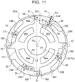
- a vibration damping device 20X illustrated in FIG. 11 in addition, the guide portions 235 in the vibration damping device 20 may be omitted, and connecting rods 35 illustrated in the drawing may be used instead.
- the connecting rods 35 are each rotatably coupled to the crank member 22 via a second coupling shaft 24X, and rotatably coupled to the projecting portion 232 of an inertial mass body 23X via a third coupling shaft 30.
- Such a vibration damping device 20X is also designed on the basis of the above formula (1) or (2) to achieve functions and effects that are similar to those of the vibration damping device 20.
- design values of the moments of inertia J 1 and J 2 , the interaxial distances L3 and L4, and the mass m can be determined through numerical calculation using software such as the LMS Imagine.Lab Amesim discussed above, for example.
- FIG. 12 is an enlarged view illustrating another vibration damping device 20Y according to the present disclosure.
- FIG. 13 is an enlarged sectional view illustrating an essential portion of the vibration damping device 20Y.
- the vibration damping device 20Y illustrated in the drawings includes: a driven plate 16Y that serves as a support member configured in the same manner as the first driven plate 16; a plurality of (e.g. four in the present embodiment) weight bodies 22Y that serve as a restoring force generation member rotatably coupled to the first driven plate 16 via respective coupling shafts 214; and a single annular inertial mass body 23Y coupled to the driven plate 16Y and the weight bodies 22Y via the coupling shafts 214.
- the driven plate 16Y has a plurality of (e.g. four at intervals of 90° in the present embodiment) long holes (through holes) 16h (first guide portion) disposed in the outer peripheral portion of the driven plate 16Y at intervals (equal intervals) in the circumferential direction.
- the long holes 16h each guide the coupling shaft 214, that is, the weight body 22Y, which is formed in a solid (or hollow) round bar shape, and are each formed in the driven plate 16Y such that the center axis which extends in the longitudinal direction extends in the radial direction of the driven plate 16Y to pass through the center of rotation RC.
- the width (the inner dimension in a direction that is orthogonal to the longitudinal direction) of the long hole 16h is determined to be slightly larger than the outside diameter of the coupling shaft 214.
- the weight bodies 22Y each have two plate members 220Y coupled to each other via the coupling shaft 214.
- the plate members 220Y are each formed in a disc shape from a metal plate.
- the coupling shaft 214 is fixed (coupled) to the two plate members 220Y such that the axis of the coupling shaft 214 passes through the center of gravity G of the weight body 22Y.
- the inertial mass body 23Y includes two annular members 230Y formed from a metal plate.
- the weight of the inertial mass body 23Y (two annular members 230Y) is determined to be sufficiently larger than the weight of one weight body 22Y.
- the annular members 230Y each have a plurality of (e.g. four at intervals of 90° in the present embodiment) guide portions 235Y (second guide portion) disposed at intervals (equal intervals) in the circumferential direction.
- the guide portions 235Y are each an opening portion that extends arcuately, and each guide the coupling shaft 214, that is, the weight body 22Y.
- the guide portions 235Y each include: a guide surface 236 in a recessed curved surface shape; a support surface 237 in a projecting curved surface shape provided on the inner peripheral side of the annular member 230Y (a portion close to the center of the annular members 230Y) with respect to the guide surface 236 to face the guide surface 236; and two stopper surfaces 238 that are continuous with the guide surface 236 and the support surface 237 on both sides of the guide surface 236 and the support surface 237.
- the guide surface 236 is a recessed circular columnar surface that has a constant radius of curvature.
- the support surface 237 is a projecting curved surface that extends arcuately.
- the stopper surfaces 238 are each a recessed curved surface that extends arcuately.
- the clearance between the guide surface 236 and the support surface 237 is determined to be slightly larger than the outside diameter of the coupling shaft 214.
- the guide portion 235Y (the guide surface 236, the support surface 237, and the stopper surfaces 238) are formed to be transversely symmetrical with respect to a line that passes through the center of curvature of the guide surface 236 and the center of the annular members 230Y (the center of rotation RC of the driven plate 16Y).
- the two annular members 230Y are disposed coaxially with the driven plate 16Y on both sides in the axial direction of the driven plate 16Y, with one annular member 230Y on each side, such that the guide portions 235Y corresponding to each other face each other in the axial direction of the annular members 230Y.
- the inner peripheral surfaces of the two annular members 230Y are supported by a plurality of protrusions 16p (see FIG. 12 ) provided on the driven plate 16Y and projecting in the axial direction. Consequently, the annular members 230Y (inertial mass body 23Y) are supported by the driven plate 16Y so as to be rotatable about the center of rotation RC.
- the two plate members 220Y are disposed so as to face each other in the axial direction via the corresponding driven plate 16Y and two annular members 230Y, and are coupled to each other by the coupling shaft 214.
- the coupling shaft 214 which couples the two plate members 220Y to each other penetrates the associated long hole 16h of the driven plate 16Y and the associated guide portions 235Y of the two annular members 230Y.
- the driven plate 16Y, the weight bodies 22Y, and the inertial mass body 23Y are coupled to each other via the coupling shafts 214, and the coupling shafts 214 are each movable along both the associated long hole 16h of the driven plate 16Y and the associated guide portions 235Y of the inertial mass body 23Y.
- the weight bodies 22Y (coupling shaft 214) constitute a sliding pair with the driven plate 16Y and the inertial mass body 23Y, and the driven plate 16Y and the inertial mass body 23Y constitute a turning pair. Consequently, the driven plate 16Y which has the long holes 16h, the plurality of weight bodies 22Y, and the inertial mass body 23Y which has the guide portions 235Y constitute a slider crank mechanism (double slider crank chain).
- the vibration damping device 20Y is in the equilibrium state when the coupling shafts 214 are positioned at the center of the guide portions 235Y in the circumferential direction and positioned at end portions of the long holes 16h on the radially outer side (see FIG. 12 ).
- each of the coupling shafts 214 which couples the two plate members 220Y to each other is pressed against the guide surfaces 236 of the guide portions 235Y of the inertial mass body 23Y by the action of a centrifugal force on the weight body 22Y to roll or slide on the guide surfaces 236 toward first end portions of the guide portions 235Y.
- the coupling shaft 214 is moved in the radial direction of the driven plate 16Y along the long hole 16h of the driven plate 16Y toward an end portion of the long hole 16h on the radially inner side.
- the weight body 22Y is reciprocally moved (swung) in the radial direction with respect to the driven plate 16Y in the long hole 16h, and reciprocally moved (swung) with respect to the inertial mass body 23Y along the guide portions 235Y.
- the inertial mass body 23Y is swung (reciprocally rotated) about the center of rotation RC of the first driven plate 16 along with movement (swinging motion) of the weight body 22Y.
- vibration that is opposite in phase to vibration transferred from the engine EG to the drive member 11 is applied from the inertial mass body 23 which is swung to the driven plate 16Y via the guide portions 235Y and the coupling shafts 214, which makes it possible to damp vibration of the driven plate 16Y.
- the distance between the center of gravity G of the weight bodies 22Y and the support point for swinging motion of the weight bodies 22Y along the guide portions 235Y (second guide portion) may be defined as "L3”
- the distance between the support point for swinging motion of the weight bodies 22Y along the guide portions 235Y and the center of rotation RC may be defined as "L4" (see FIG. 12 ).
- the support point for swinging motion of the weight bodies 22Y along the guide portions 235Y coincides with the center of curvature of the guide surfaces 236 (guide portions 235Y).
- L 4 / L 3 + L 4 ⁇ + ⁇ ⁇ n + ⁇ L 4 / L 3 + L 4 > ⁇ + ⁇ ⁇ n + ⁇
- the vibration damping device 20Y may be provided with a plurality of cylindrical outer rings 27Y rotatably supported by the coupling shaft 214 via a plurality of rollers (or balls, i.e. rolling bodies) 26Y to constitute rolling bearings.
- three outer rings 27Y are mounted on the coupling shaft 214 so as to roll or slide on the inner surface of the long hole 16h of the driven plate 16Y and the guide portions 235Y (guide surfaces 236) of the inertial mass body 23Y (annular members 230Y). Consequently, it is possible to swing the weight bodies 22Y and the inertial mass body 23Y more smoothly.
- the guide surface 236 of the guide portion 235Y is a recessed circular columnar surface that has a constant radius of curvature.
- the guide surface 236 may be a recessed curved surface formed such that the radius of curvature is varied stepwise or gradually.
- the support surface 237 and the stopper surfaces 238 may be omitted from the guide portion 235Y.
- the inertial mass body 23Y does not necessarily need to be supported so as to be rotatable about the center of rotation RC by the driven plate 16Y.
- Swinging motion of the inertial mass body 23 can be made transversely symmetrical by forming the long hole 16h in the driven plate 16Y such that the center axis of the long hole 16h extends in the radial direction of the driven plate 16Y to pass through the center of rotation RC.
- the long hole 16h is not limited thereto. That is, as illustrated in FIG. 15 , the long hole 16h may be formed in the driven plate 16Y such that the center axis of the long hole 16h extends arcuately. In this case, as illustrated in FIG.
- the vibration damping device 20Y can be caused to operate in the same manner as the vibration damping device 20 by determining the center of curvature of the center axis of the long hole 16h on the center axis of the first coupling shaft 21 in the vibration damping device 20, and causing the radius of curvature of the center axis of the long hole 16h to coincide with the interaxial distance L2 between the first coupling shaft 21 and the second coupling shaft 24 in the vibration damping device 20.
- the vibration damping device 20Y which is a slider crank mechanism may include: two driven plates 16Y that serve as a support member; an inertial mass body 23Y that is a single annular member disposed between the two driven plates 16Y in the axial direction; and a plurality of weight bodies 22Y each guided by long holes 16h of the driven plates 16Y and a guide portion 235Y (guide surface 236) of the inertial mass body 23Y.
- the weight bodies 22Y may each include a body 22a with a large diameter guided by the guide portion 235Y of the inertial mass body 23Y and shaft portions 22b that extend from the body 22a toward both sides in the axial direction so as to be guided by the long holes 16h of the respective driven plates 16Y.
- a guide portion (second guide portion) corresponding to the guide portion 235Y may be formed in the weight body 22Y, and the coupling shaft 214 may be coupled (fixed) to the inertial mass body 23Y.
- a first guide portion corresponding to the long hole 16h may be provided in the weight body 22Y.
- a second guide portion corresponding to the guide portion 235Y may be provided in either the driven plates 16Y (support member) or the inertial mass body 23Y, and the coupling shaft 214 may be provided on the other of the driven plates 16Y and the inertial mass body 23Y.
- a first guide portion corresponding to the long hole 16h may be provided in the inertial mass body 23Y.
- a second guide portion corresponding to the guide portion 235Y may be provided in either the driven plates 16Y or the weight body 22Y, and the coupling shaft 214 may be provided on the other of the driven plates 16Y and the weight body 22Y.
- the vibration damping device 20, 20X, 20Y may be coupled to the intermediate member 12 of the damper device 10, or may be coupled to the drive member (input element) 11 (see the dash-double-dot line in FIG. 1 ).
- the vibration damping device 20, 20X, 20Y may be applied to a damper device 10B illustrated in FIG. 17 .
- the damper device 10B of FIG. 17 corresponds to the damper device 10 from which the intermediate member 12 has been omitted, and includes the drive member (input element) 11 and the driven member 15 (output element) as rotary elements, and also includes springs SP disposed between the drive member 11 and the driven member 15 as a torque transfer element.
- the vibration damping device 20, 20X, 20Y may be coupled to the driven member 15 of the damper device 10B as illustrated in the drawing, or may be coupled to the drive member 11 as indicated by the dash-double-dot line in the drawing.
- the vibration damping device 20, 20X, 20Y may be applied to a damper device 10C illustrated in FIG. 18 .
- the damper device 10C of FIG. 18 includes the drive member (input element) 11, a first intermediate member (first intermediate element) 121, a second intermediate member (second intermediate element) 122, and the driven member (output element) 15 as rotary elements, and also includes first springs SP1 disposed between the drive member 11 and the first intermediate member 121, second springs SP2 disposed between the second intermediate member 122 and the driven member 15, and third spring SP3 disposed between the first intermediate member 121 and the second intermediate member 122 as torque transfer elements.
- the vibration damping device 20, 20X, 20Y may be coupled to the driven member 15 of the damper device 10C as illustrated in the drawing, or may be coupled to the first intermediate member 121, the second intermediate member 122, or the drive member 11 as indicated by the dash-double-dot line in the drawing.
- the vibration damping device 20, 20X, 20Y may be coupled to a rotary element of the damper device 10, 10B, or 10C, it is possible to damp vibration significantly well using both the damper device 10 to 10C and the vibration damping device 20, 20X, 20Y while suppressing an increase in weight of the damper device 10 to 10C.
- a vibration damping device (20, 20X, 20Y) disposed in an oil chamber (9) and including: a support member (16, 16Y) that rotates together with a rotary element (15), to which torque from an engine (EG) is transferred, about a center of rotation (RC) of the rotary element (15); a restoring force generation member (22, 22Y) that is coupled to the support member (16, 16Y) and that is swingable along with rotation of the support member (16, 16Y); and an inertial mass body (23, 23X, 23Y) coupled to the support member (16, 16Y) via the restoring force generation member (22, 22Y) and swung about the center of rotation (RC) in conjunction with the restoring force generation member (22, 22Y) along with rotation of the support member (16, 16Y).
- an order (q eff ) of the vibration damping device (20, 20X, 20Y) is larger than a sum of an excitation order (q tag ) of the engine (EG) and an offset value ( ⁇ q) determined in consideration of an effect of oil in the oil chamber (9), and a reference order (q ref ), which is a convergent value of the order (q eff ) of the vibration damping device which operates in the oil chamber (9) when an amplitude ( ⁇ ) of vibration of input torque transferred to the rotary element (15) becomes smaller, is higher than the excitation order (q tag ).
- the studies conducted by the inventors revealed that the vibration damping performance of the vibration damping device, which included the restoring force generation member and the inertial mass body which was swung in conjunction with the restoring force generation member, was further improved by making the reference order, which was a convergence value of the order of the vibration damping device when the amplitude of vibration of the input torque became smaller, higher than the excitation order of the engine, rather than by causing the reference order to coincide with the excitation order.
- the vibration damping device which is disposed in the oil chamber, it is possible to further improve the vibration damping performance of the vibration damping device, which includes the restoring force generation member and the inertial mass body which is swung in conjunction with the restoring force generation member, by making the order of the vibration damping device larger than the sum of the excitation order of the engine and an offset value determined in consideration of the effect of oil in the oil chamber and making the reference order higher than the excitation order of the engine.
- the vibration damping device (20, 20X, 20Y) may be designed such that when the reference order is defined as "q ref " and the excitation order is defined as "q tag ", 1.00 ⁇ q tag ⁇ q ref ⁇ 1.03 ⁇ q tag (more preferably 1.01 ⁇ q tag ⁇ q ref ⁇ 1.02 ⁇ q tag ) is met. Consequently, it is possible to improve the vibration damping performance of the vibration damping device, which includes the restoring force generation member and the inertial mass body which is swung in conjunction with the restoring force generation member, significantly well.
- the vibration damping device (20, 20X, 20Y) may be designed such that the order (q eff ) of the vibration damping device becomes higher, or the order (q eff ) is not varied, as the amplitude ( ⁇ ) of the vibration of the input torque becomes larger. Consequently, a reduction in vibration damping performance due to a deviation of the order in a region in which the rotational speed of the engine is low can be suppressed even if there occurs a deviation of the order of the vibration damping device as the amplitude of vibration of the input torque becomes larger. As a result, it is possible to further improve the vibration damping performance in the region in which the rotational speed of the engine is low.
- the vibration damping device (20Y) may further include: a first guide portion (16h) that is provided in one of the support member (16Y), the restoring force generation member (22Y), and the inertial mass body (23Y) and that extends along a radial direction of the support member (16Y); and a second guide portion (235Y) that is formed in one of two other than the one of the support member (16Y), the restoring force generation member (22Y), and the inertial mass body (23Y) and that extends arcuately, and the other of the two other than the one of the support member (16Y), the restoring force generation member (22Y), and the inertial mass body (23Y) may be guided by the first and second guide portions (16h, 235Y).
- a vibration damping device it is possible to further improve the vibration damping performance, while suppressing an increase in weight or size of the entire device, by causing the order of the vibration damping device to become higher as the amplitude of vibration of the input torque becomes larger.
- the vibration damping device (20) may further include: a first coupling shaft (21) that couples the support member (16) and the restoring force generation member (22) so as to be rotatable relative to each other; a second coupling shaft (24) that is supported by one of the restoring force generation member (22) and the inertial mass body (23) and that couples the restoring force generation member (22) and the inertial mass body (23) so as to be rotatable relative to each other; and a guide portion (235, 235X) that is formed in the other of the restoring force generation member (22) and the inertial mass body (23) and that guides the second coupling shaft (24) such that the second coupling shaft (24) is swung about the first coupling shaft (21) while keeping an interaxial distance (L2) between the first coupling shaft (21) and the second coupling shaft (24) constant, and such that the second coupling shaft (24) is swung about a virtual shaft (25), a relative position of which with respect to the inertial mass body (23) is determined to be invariable
- the vibration damping device (20X) may further include a connecting member (35) rotatably coupled to the restoring force generation member (22) via a second coupling shaft (24) and rotatably coupled to the inertial mass body (23X) via a third coupling shaft (30).
- the vibration damping device (20, 20X) may meet L1 + L2 > L3 + L4.
- the effect of the weight of the restoring force generation member on the equivalent mass of the vibration damping device can be made very small, which can further improve the degree of freedom in setting of the equivalent rigidity and the equivalent mass, that is, the vibration order.
- the support member (16, 16Y) may rotate coaxially and together with a rotary element of a damper device (10, 10B, 10C) that has a plurality of rotary elements (11, 12, 121, 122, 15) that include at least an input element (11) and an output element (15), and an elastic body (SP, SP1, SP2, SP3) that transfers torque between the input element (11) and the output element (15).
- the output element (15) of the damper device (10, 10B, 10C) may be functionally (directly or indirectly) coupled to an input shaft (Is) of a transmission (TM).
- the present disclosure also provides a method of designing a vibration damping device (20, 20X, 20Y) including: a support member (16, 16Y) that rotates together with a rotary element (15), to which torque from an engine (EG) is transferred, about a center of rotation (RC) of the rotary element (15); a restoring force generation member (22, 22Y) that is coupled to the support member (16, 16Y) and that is swingable along with rotation of the support member (16, 16Y); and an inertial mass body (23, 23X, 23Y) coupled to the support member (16, 16Y) via the restoring force generation member (22, 22Y) and swung about the center of rotation (RC) in conjunction with the restoring force generation member (22, 22Y) along with rotation of the support member (16, 16Y)
- the method includes: preparing a dynamic model that includes the vibration damping device (20, 20X, 20Y) and a vibration suppression target (DS) to which torque from the engine (EG) is transferred (step S100); deriving, for each
- the vibration damping device By designing the vibration damping device by such a method, it is possible to further improve the vibration damping performance by causing the reference order, which is a convergent value of the order of the vibration damping device, to fall within an adequate range that is larger than the excitation order of the engine.
- the target value may be determined to be smaller than the torque fluctuations (T Fluc ) of the vibration suppression target (DS) when a reference order (q ref ), which is a convergent value of the order of the vibration damping device (20, 20X, 20Y), coincides with an excitation order (q tag ) of the engine (EG).
- T Fluc torque fluctuations
- q ref reference order
- the dynamic model may simulate a structure of a vehicle from the engine (EG) to wheels (W), including the vibration damping device (20, 20X, 20Y) and the vibration suppression target (DS).
- the torque fluctuations (T Fluc ) may be derived while changing the design parameter (J 1 , J 2 , L3, L4, m) such that a reference order (q ref ), which is a convergent value of the order (q eff ) of the vibration damping device (20, 20X, 20Y) when an amplitude of vibration of torque transferred to the rotary element (15) becomes smaller, becomes higher (steps S100 to S140), and the design parameter (J 1 , J 2 , L3, L4, m) which brings a peak value of the torque fluctuations (T Fluc ) in a predetermined rotational speed range to a minimum value (MIN) or a value around the minimum value may be determined as the design value (steps S150 and S160).
- a reference order (q ref ) which is a convergent value of the order (q eff ) of the vibration damping device (20, 20X, 20Y) when an amplitude of vibration of torque transferred to the rotary element (15) becomes smaller, becomes higher (steps S100 to
- the present disclosure further provides a vibration damping device (20, 20X, 20Y) of a dry type, including: a support member (16, 16Y) that rotates together with a rotary element (15), to which torque from an engine (EG) is transferred, about a center of rotation (RC) of the rotary element (15); a restoring force generation member (22, 22Y) that is coupled to the support member (16, 16Y) and that is swingable along with rotation of the support member (16, 16Y); and an inertial mass body (23, 23X, 23Y) coupled to the support member (16, 16Y) via the restoring force generation member (22, 22Y) and swung about the center of rotation (RC) in conjunction with the restoring force generation member (22, 22Y) along with rotation of the support member (16, 16Y).
- a vibration damping device (20, 20X, 20Y) of a dry type including: a support member (16, 16Y) that rotates together with a rotary element (15), to which torque from an engine (EG) is transferred, about
- a reference order (q ref ) which is a convergent value of an order (q eff ) of the vibration damping device when an amplitude ( ⁇ ) of vibration of input torque transferred to the rotary element becomes smaller, is higher than an excitation order (q tag ) of the engine (EG).
- the vibration damping device of a dry type which includes the restoring force generation member and the inertial mass body which is swung in conjunction with the restoring force generation member, by making the reference order higher than the excitation order of the engine.
- the vibration damping device (20, 20X, 20Y) of a dry type may be designed such that when the reference order is defined as "q ref " and the excitation order is defined as "qtag", 1.00 ⁇ q tag ⁇ q ref ⁇ 1.03 ⁇ q tag , more preferably 1.01 ⁇ q tag ⁇ q ref ⁇ 1.02 ⁇ q tag , is met. Consequently, it is possible to improve the vibration damping performance of the vibration damping device of a dry type, which includes the restoring force generation member and the inertial mass body which is swung in conjunction with the restoring force generation member, significantly well.
- the invention according to the present disclosure can be utilized in the field of manufacture of vibration damping devices that damp vibration of a rotary element.
Landscapes
- Engineering & Computer Science (AREA)
- General Engineering & Computer Science (AREA)
- Mechanical Engineering (AREA)
- Physics & Mathematics (AREA)
- Acoustics & Sound (AREA)
- Aviation & Aerospace Engineering (AREA)
- Vibration Prevention Devices (AREA)
- Mechanical Operated Clutches (AREA)
Applications Claiming Priority (3)
| Application Number | Priority Date | Filing Date | Title |
|---|---|---|---|
| JP2016052599 | 2016-03-16 | ||
| JP2016159617 | 2016-08-16 | ||
| PCT/JP2017/010794 WO2017159827A1 (ja) | 2016-03-16 | 2017-03-16 | 振動減衰装置およびその設計方法 |
Publications (2)
| Publication Number | Publication Date |
|---|---|
| EP3385568A1 true EP3385568A1 (de) | 2018-10-10 |
| EP3385568A4 EP3385568A4 (de) | 2018-12-19 |
Family
ID=59851589
Family Applications (1)
| Application Number | Title | Priority Date | Filing Date |
|---|---|---|---|
| EP17766822.5A Pending EP3385568A4 (de) | 2016-03-16 | 2017-03-16 | Schwingungsdämpfungsvorrichtung und entwurfsverfahren dafür |
Country Status (6)
| Country | Link |
|---|---|
| US (1) | US10480615B2 (de) |
| EP (1) | EP3385568A4 (de) |
| JP (1) | JP6566119B2 (de) |
| KR (1) | KR20180102138A (de) |
| CN (1) | CN108713113B (de) |
| WO (1) | WO2017159827A1 (de) |
Cited By (1)
| Publication number | Priority date | Publication date | Assignee | Title |
|---|---|---|---|---|
| EP3768988B1 (de) * | 2018-03-19 | 2022-02-09 | Schaeffler Technologies AG & Co. KG | Tilgereinrichtung sowie drehmomentübertragungseinrichtung |
Families Citing this family (7)
| Publication number | Priority date | Publication date | Assignee | Title |
|---|---|---|---|---|
| US20190257398A1 (en) * | 2016-09-09 | 2019-08-22 | Aisin Aw Co., Ltd. | Vibration damping device |
| JP6769655B2 (ja) * | 2016-09-29 | 2020-10-14 | アイシン・エィ・ダブリュ株式会社 | 振動減衰装置およびその設計方法 |
| US20190257384A1 (en) * | 2018-02-20 | 2019-08-22 | GM Global Technology Operations LLC | Isolator assembly and a vehicle including the isolator assembly |
| DE102018112285A1 (de) * | 2018-05-23 | 2019-11-28 | Schaeffler Technologies AG & Co. KG | Ringpendeleinrichtung |
| JP7087947B2 (ja) * | 2018-11-20 | 2022-06-21 | 株式会社アイシン | 振動減衰装置およびその設計方法 |
| US20200256442A1 (en) * | 2019-02-07 | 2020-08-13 | GM Global Technology Operations LLC | Torque converter clutch |
| CN113124052B (zh) * | 2021-04-16 | 2022-08-23 | 中国航空发动机研究院 | 电磁轴承-转子系统不平衡振动控制方法及电子设备 |
Family Cites Families (21)
| Publication number | Priority date | Publication date | Assignee | Title |
|---|---|---|---|---|
| JPH01312246A (ja) | 1988-06-13 | 1989-12-18 | Nissan Motor Co Ltd | 定次数形ダイナミックダンパ |
| JP2001263424A (ja) | 2000-03-17 | 2001-09-26 | Valeo Unisia Transmission Kk | ダイナミックダンパ |
| WO2009067988A1 (de) * | 2007-11-29 | 2009-06-04 | Luk Lamellen Und Kupplungsbau Beteiligungs Kg | Kraftübertragungsvorrichtung mit einem drehzahladaptiven tilger und verfahren zu verbesserung des dämpfungsverhaltens |
| JP5445423B2 (ja) | 2010-10-07 | 2014-03-19 | トヨタ自動車株式会社 | ダイナミックダンパ |
| DE102011010087A1 (de) * | 2011-02-01 | 2012-08-02 | Audi Ag | Anordnung mit Verbrennungskraftmaschine und daran angekoppeltem Planetengetriebe |
| DE102011076790B4 (de) | 2011-05-31 | 2023-07-13 | Zf Friedrichshafen Ag | Antriebssystem für ein Fahrzeug |
| DE102012212854A1 (de) | 2011-08-08 | 2013-02-14 | Schaeffler Technologies AG & Co. KG | Drehschwingungstilger |
| JP5844601B2 (ja) * | 2011-10-18 | 2016-01-20 | ジヤトコ株式会社 | 振動減衰装置 |
| JP5970367B2 (ja) * | 2012-12-26 | 2016-08-17 | アイシン・エィ・ダブリュ株式会社 | 遠心振子式吸振装置およびその次数設定方法 |
| JP5944308B2 (ja) * | 2012-12-26 | 2016-07-05 | アイシン・エィ・ダブリュ株式会社 | 遠心振子式吸振装置およびその次数設定方法 |
| US9683627B2 (en) | 2013-10-31 | 2017-06-20 | Valeo Embrayages | Mechanism for filtering torque fluctuations of secondary member |
| US10132384B2 (en) * | 2014-01-17 | 2018-11-20 | Aisin Aw Co., Ltd. | Centrifugal pendulum-type vibration absorbing device and order setting method for the same |
| WO2015151654A1 (ja) | 2014-03-31 | 2015-10-08 | アイシン・エィ・ダブリュ株式会社 | 遠心振子式吸振装置およびその設計方法 |
| FR3020849B1 (fr) | 2014-05-12 | 2017-07-07 | Valeo Embrayages | Mecanisme de filtration de fluctuations de couple |
| JP2016014425A (ja) * | 2014-07-02 | 2016-01-28 | アイシン・エィ・ダブリュ株式会社 | 遠心振子式吸振装置 |
| WO2016047789A1 (ja) * | 2014-09-25 | 2016-03-31 | アイシン・エィ・ダブリュ株式会社 | ダンパ装置 |
| US9720541B2 (en) * | 2015-06-30 | 2017-08-01 | Synaptics Incorporated | Arrangement of sensor pads and display driver pads for input device |
| JP6505003B2 (ja) * | 2015-07-17 | 2019-04-24 | アイシン・エィ・ダブリュ株式会社 | 振動減衰装置 |
| DE112016003639T8 (de) | 2015-09-30 | 2018-06-28 | Aisin Aw Co., Ltd. | Schwingungsdämpfungsvorrichtung |
| DE112017000349T5 (de) * | 2016-03-16 | 2018-09-27 | Aisin Aw Co., Ltd. | Schwingungsdämpfungsvorrichtung |
| JP6769655B2 (ja) * | 2016-09-29 | 2020-10-14 | アイシン・エィ・ダブリュ株式会社 | 振動減衰装置およびその設計方法 |
-
2017
- 2017-03-16 US US16/070,419 patent/US10480615B2/en active Active
- 2017-03-16 WO PCT/JP2017/010794 patent/WO2017159827A1/ja active Application Filing
- 2017-03-16 EP EP17766822.5A patent/EP3385568A4/de active Pending
- 2017-03-16 JP JP2018506027A patent/JP6566119B2/ja active Active
- 2017-03-16 CN CN201780014514.4A patent/CN108713113B/zh active Active
- 2017-03-16 KR KR1020187023101A patent/KR20180102138A/ko not_active Application Discontinuation
Cited By (1)
| Publication number | Priority date | Publication date | Assignee | Title |
|---|---|---|---|---|
| EP3768988B1 (de) * | 2018-03-19 | 2022-02-09 | Schaeffler Technologies AG & Co. KG | Tilgereinrichtung sowie drehmomentübertragungseinrichtung |
Also Published As
| Publication number | Publication date |
|---|---|
| KR20180102138A (ko) | 2018-09-14 |
| US20190024752A1 (en) | 2019-01-24 |
| CN108713113B (zh) | 2020-02-21 |
| JPWO2017159827A1 (ja) | 2018-10-18 |
| CN108713113A (zh) | 2018-10-26 |
| US10480615B2 (en) | 2019-11-19 |
| EP3385568A4 (de) | 2018-12-19 |
| JP6566119B2 (ja) | 2019-08-28 |
| WO2017159827A1 (ja) | 2017-09-21 |
Similar Documents
| Publication | Publication Date | Title |
|---|---|---|
| EP3385568A1 (de) | Schwingungsdämpfungsvorrichtung und entwurfsverfahren dafür | |
| JP6489228B2 (ja) | 振動減衰装置 | |
| JP6150009B2 (ja) | 遠心振子式吸振装置およびその設計方法 | |
| US11204078B2 (en) | Vibration damping device | |
| EP3284969A1 (de) | Schwingungsdämpfungsvorrichtung | |
| US10508709B2 (en) | Vibration damping device and method for designing the same | |
| US11668369B2 (en) | Vibration damping device and design method of the same | |
| US20200378448A1 (en) | Vibration damping device | |
| US20190003554A1 (en) | Vibration damping device | |
| WO2018199323A1 (ja) | 振動減衰装置 | |
| CN111133222B (zh) | 振动衰减装置 | |
| WO2018199324A1 (ja) | 振動減衰装置 | |
| JP2018173105A (ja) | 振動減衰装置 |
Legal Events
| Date | Code | Title | Description |
|---|---|---|---|
| STAA | Information on the status of an ep patent application or granted ep patent |
Free format text: STATUS: THE INTERNATIONAL PUBLICATION HAS BEEN MADE |
|
| PUAI | Public reference made under article 153(3) epc to a published international application that has entered the european phase |
Free format text: ORIGINAL CODE: 0009012 |
|
| STAA | Information on the status of an ep patent application or granted ep patent |
Free format text: STATUS: REQUEST FOR EXAMINATION WAS MADE |
|
| 17P | Request for examination filed |
Effective date: 20180702 |
|
| AK | Designated contracting states |
Kind code of ref document: A1 Designated state(s): AL AT BE BG CH CY CZ DE DK EE ES FI FR GB GR HR HU IE IS IT LI LT LU LV MC MK MT NL NO PL PT RO RS SE SI SK SM TR |
|
| AX | Request for extension of the european patent |
Extension state: BA ME |
|
| STAA | Information on the status of an ep patent application or granted ep patent |
Free format text: STATUS: EXAMINATION IS IN PROGRESS |
|
| A4 | Supplementary search report drawn up and despatched |
Effective date: 20181119 |
|
| RIC1 | Information provided on ipc code assigned before grant |
Ipc: F16H 45/02 20060101ALI20181113BHEP Ipc: F16F 15/14 20060101AFI20181113BHEP Ipc: F16F 15/12 20060101ALI20181113BHEP Ipc: F16F 15/134 20060101ALI20181113BHEP |
|
| 17Q | First examination report despatched |
Effective date: 20181205 |
|
| DAV | Request for validation of the european patent (deleted) | ||
| DAX | Request for extension of the european patent (deleted) | ||
| STAA | Information on the status of an ep patent application or granted ep patent |
Free format text: STATUS: EXAMINATION IS IN PROGRESS |
|
| RAP1 | Party data changed (applicant data changed or rights of an application transferred) |
Owner name: AISIN CORPORATION |
|
| GRAP | Despatch of communication of intention to grant a patent |
Free format text: ORIGINAL CODE: EPIDOSNIGR1 |
|
| STAA | Information on the status of an ep patent application or granted ep patent |
Free format text: STATUS: GRANT OF PATENT IS INTENDED |
|
| INTG | Intention to grant announced |
Effective date: 20240314 |