EP3385080B1 - Recording apparatus and recording method - Google Patents
Recording apparatus and recording method Download PDFInfo
- Publication number
- EP3385080B1 EP3385080B1 EP18164619.1A EP18164619A EP3385080B1 EP 3385080 B1 EP3385080 B1 EP 3385080B1 EP 18164619 A EP18164619 A EP 18164619A EP 3385080 B1 EP3385080 B1 EP 3385080B1
- Authority
- EP
- European Patent Office
- Prior art keywords
- driving
- heating
- sub
- recording
- heater
- Prior art date
- Legal status (The legal status is an assumption and is not a legal conclusion. Google has not performed a legal analysis and makes no representation as to the accuracy of the status listed.)
- Active
Links
- 238000000034 method Methods 0.000 title claims description 7
- 238000010438 heat treatment Methods 0.000 claims description 149
- 239000000758 substrate Substances 0.000 claims description 16
- 238000001514 detection method Methods 0.000 claims description 15
- 230000015654 memory Effects 0.000 claims description 15
- 238000007599 discharging Methods 0.000 claims description 10
- 238000010586 diagram Methods 0.000 description 25
- 230000000694 effects Effects 0.000 description 12
- 238000003491 array Methods 0.000 description 9
- 238000006243 chemical reaction Methods 0.000 description 8
- 230000006698 induction Effects 0.000 description 7
- 230000005540 biological transmission Effects 0.000 description 5
- 238000010792 warming Methods 0.000 description 4
- 230000002349 favourable effect Effects 0.000 description 3
- 239000003086 colorant Substances 0.000 description 2
- XUIMIQQOPSSXEZ-UHFFFAOYSA-N Silicon Chemical compound [Si] XUIMIQQOPSSXEZ-UHFFFAOYSA-N 0.000 description 1
- 230000004913 activation Effects 0.000 description 1
- 230000009286 beneficial effect Effects 0.000 description 1
- 230000014759 maintenance of location Effects 0.000 description 1
- 238000005259 measurement Methods 0.000 description 1
- 238000013139 quantization Methods 0.000 description 1
- 238000001454 recorded image Methods 0.000 description 1
- 229910052710 silicon Inorganic materials 0.000 description 1
- 239000010703 silicon Substances 0.000 description 1
- 230000003068 static effect Effects 0.000 description 1
Images


Classifications
-
- B—PERFORMING OPERATIONS; TRANSPORTING
- B41—PRINTING; LINING MACHINES; TYPEWRITERS; STAMPS
- B41J—TYPEWRITERS; SELECTIVE PRINTING MECHANISMS, i.e. MECHANISMS PRINTING OTHERWISE THAN FROM A FORME; CORRECTION OF TYPOGRAPHICAL ERRORS
- B41J2/00—Typewriters or selective printing mechanisms characterised by the printing or marking process for which they are designed
- B41J2/005—Typewriters or selective printing mechanisms characterised by the printing or marking process for which they are designed characterised by bringing liquid or particles selectively into contact with a printing material
- B41J2/01—Ink jet
- B41J2/135—Nozzles
- B41J2/14—Structure thereof only for on-demand ink jet heads
-
- B—PERFORMING OPERATIONS; TRANSPORTING
- B41—PRINTING; LINING MACHINES; TYPEWRITERS; STAMPS
- B41J—TYPEWRITERS; SELECTIVE PRINTING MECHANISMS, i.e. MECHANISMS PRINTING OTHERWISE THAN FROM A FORME; CORRECTION OF TYPOGRAPHICAL ERRORS
- B41J2/00—Typewriters or selective printing mechanisms characterised by the printing or marking process for which they are designed
- B41J2/005—Typewriters or selective printing mechanisms characterised by the printing or marking process for which they are designed characterised by bringing liquid or particles selectively into contact with a printing material
- B41J2/01—Ink jet
- B41J2/015—Ink jet characterised by the jet generation process
- B41J2/04—Ink jet characterised by the jet generation process generating single droplets or particles on demand
- B41J2/045—Ink jet characterised by the jet generation process generating single droplets or particles on demand by pressure, e.g. electromechanical transducers
- B41J2/04501—Control methods or devices therefor, e.g. driver circuits, control circuits
- B41J2/04528—Control methods or devices therefor, e.g. driver circuits, control circuits aiming at warming up the head
-
- B—PERFORMING OPERATIONS; TRANSPORTING
- B41—PRINTING; LINING MACHINES; TYPEWRITERS; STAMPS
- B41J—TYPEWRITERS; SELECTIVE PRINTING MECHANISMS, i.e. MECHANISMS PRINTING OTHERWISE THAN FROM A FORME; CORRECTION OF TYPOGRAPHICAL ERRORS
- B41J2/00—Typewriters or selective printing mechanisms characterised by the printing or marking process for which they are designed
- B41J2/005—Typewriters or selective printing mechanisms characterised by the printing or marking process for which they are designed characterised by bringing liquid or particles selectively into contact with a printing material
- B41J2/01—Ink jet
- B41J2/015—Ink jet characterised by the jet generation process
- B41J2/04—Ink jet characterised by the jet generation process generating single droplets or particles on demand
- B41J2/045—Ink jet characterised by the jet generation process generating single droplets or particles on demand by pressure, e.g. electromechanical transducers
- B41J2/04501—Control methods or devices therefor, e.g. driver circuits, control circuits
- B41J2/0452—Control methods or devices therefor, e.g. driver circuits, control circuits reducing demand in current or voltage
-
- B—PERFORMING OPERATIONS; TRANSPORTING
- B41—PRINTING; LINING MACHINES; TYPEWRITERS; STAMPS
- B41J—TYPEWRITERS; SELECTIVE PRINTING MECHANISMS, i.e. MECHANISMS PRINTING OTHERWISE THAN FROM A FORME; CORRECTION OF TYPOGRAPHICAL ERRORS
- B41J2/00—Typewriters or selective printing mechanisms characterised by the printing or marking process for which they are designed
- B41J2/005—Typewriters or selective printing mechanisms characterised by the printing or marking process for which they are designed characterised by bringing liquid or particles selectively into contact with a printing material
- B41J2/01—Ink jet
- B41J2/015—Ink jet characterised by the jet generation process
- B41J2/04—Ink jet characterised by the jet generation process generating single droplets or particles on demand
- B41J2/045—Ink jet characterised by the jet generation process generating single droplets or particles on demand by pressure, e.g. electromechanical transducers
- B41J2/04501—Control methods or devices therefor, e.g. driver circuits, control circuits
- B41J2/04531—Control methods or devices therefor, e.g. driver circuits, control circuits controlling a head having a heater in the manifold
-
- B—PERFORMING OPERATIONS; TRANSPORTING
- B41—PRINTING; LINING MACHINES; TYPEWRITERS; STAMPS
- B41J—TYPEWRITERS; SELECTIVE PRINTING MECHANISMS, i.e. MECHANISMS PRINTING OTHERWISE THAN FROM A FORME; CORRECTION OF TYPOGRAPHICAL ERRORS
- B41J2/00—Typewriters or selective printing mechanisms characterised by the printing or marking process for which they are designed
- B41J2/005—Typewriters or selective printing mechanisms characterised by the printing or marking process for which they are designed characterised by bringing liquid or particles selectively into contact with a printing material
- B41J2/01—Ink jet
- B41J2/015—Ink jet characterised by the jet generation process
- B41J2/04—Ink jet characterised by the jet generation process generating single droplets or particles on demand
- B41J2/045—Ink jet characterised by the jet generation process generating single droplets or particles on demand by pressure, e.g. electromechanical transducers
- B41J2/04501—Control methods or devices therefor, e.g. driver circuits, control circuits
- B41J2/04563—Control methods or devices therefor, e.g. driver circuits, control circuits detecting head temperature; Ink temperature
-
- B—PERFORMING OPERATIONS; TRANSPORTING
- B41—PRINTING; LINING MACHINES; TYPEWRITERS; STAMPS
- B41J—TYPEWRITERS; SELECTIVE PRINTING MECHANISMS, i.e. MECHANISMS PRINTING OTHERWISE THAN FROM A FORME; CORRECTION OF TYPOGRAPHICAL ERRORS
- B41J2/00—Typewriters or selective printing mechanisms characterised by the printing or marking process for which they are designed
- B41J2/005—Typewriters or selective printing mechanisms characterised by the printing or marking process for which they are designed characterised by bringing liquid or particles selectively into contact with a printing material
- B41J2/01—Ink jet
- B41J2/015—Ink jet characterised by the jet generation process
- B41J2/04—Ink jet characterised by the jet generation process generating single droplets or particles on demand
- B41J2/045—Ink jet characterised by the jet generation process generating single droplets or particles on demand by pressure, e.g. electromechanical transducers
- B41J2/04501—Control methods or devices therefor, e.g. driver circuits, control circuits
- B41J2/04573—Timing; Delays
-
- B—PERFORMING OPERATIONS; TRANSPORTING
- B41—PRINTING; LINING MACHINES; TYPEWRITERS; STAMPS
- B41J—TYPEWRITERS; SELECTIVE PRINTING MECHANISMS, i.e. MECHANISMS PRINTING OTHERWISE THAN FROM A FORME; CORRECTION OF TYPOGRAPHICAL ERRORS
- B41J2/00—Typewriters or selective printing mechanisms characterised by the printing or marking process for which they are designed
- B41J2/005—Typewriters or selective printing mechanisms characterised by the printing or marking process for which they are designed characterised by bringing liquid or particles selectively into contact with a printing material
- B41J2/01—Ink jet
- B41J2/015—Ink jet characterised by the jet generation process
- B41J2/04—Ink jet characterised by the jet generation process generating single droplets or particles on demand
- B41J2/045—Ink jet characterised by the jet generation process generating single droplets or particles on demand by pressure, e.g. electromechanical transducers
- B41J2/04501—Control methods or devices therefor, e.g. driver circuits, control circuits
- B41J2/0458—Control methods or devices therefor, e.g. driver circuits, control circuits controlling heads based on heating elements forming bubbles
-
- B—PERFORMING OPERATIONS; TRANSPORTING
- B41—PRINTING; LINING MACHINES; TYPEWRITERS; STAMPS
- B41J—TYPEWRITERS; SELECTIVE PRINTING MECHANISMS, i.e. MECHANISMS PRINTING OTHERWISE THAN FROM A FORME; CORRECTION OF TYPOGRAPHICAL ERRORS
- B41J2/00—Typewriters or selective printing mechanisms characterised by the printing or marking process for which they are designed
- B41J2/005—Typewriters or selective printing mechanisms characterised by the printing or marking process for which they are designed characterised by bringing liquid or particles selectively into contact with a printing material
- B41J2/01—Ink jet
- B41J2/015—Ink jet characterised by the jet generation process
- B41J2/04—Ink jet characterised by the jet generation process generating single droplets or particles on demand
- B41J2/045—Ink jet characterised by the jet generation process generating single droplets or particles on demand by pressure, e.g. electromechanical transducers
- B41J2/05—Ink jet characterised by the jet generation process generating single droplets or particles on demand by pressure, e.g. electromechanical transducers produced by the application of heat
-
- B—PERFORMING OPERATIONS; TRANSPORTING
- B41—PRINTING; LINING MACHINES; TYPEWRITERS; STAMPS
- B41J—TYPEWRITERS; SELECTIVE PRINTING MECHANISMS, i.e. MECHANISMS PRINTING OTHERWISE THAN FROM A FORME; CORRECTION OF TYPOGRAPHICAL ERRORS
- B41J2/00—Typewriters or selective printing mechanisms characterised by the printing or marking process for which they are designed
- B41J2/005—Typewriters or selective printing mechanisms characterised by the printing or marking process for which they are designed characterised by bringing liquid or particles selectively into contact with a printing material
- B41J2/01—Ink jet
- B41J2002/012—Ink jet with intermediate transfer member
-
- B—PERFORMING OPERATIONS; TRANSPORTING
- B41—PRINTING; LINING MACHINES; TYPEWRITERS; STAMPS
- B41J—TYPEWRITERS; SELECTIVE PRINTING MECHANISMS, i.e. MECHANISMS PRINTING OTHERWISE THAN FROM A FORME; CORRECTION OF TYPOGRAPHICAL ERRORS
- B41J2202/00—Embodiments of or processes related to ink-jet or thermal heads
- B41J2202/01—Embodiments of or processes related to ink-jet heads
- B41J2202/16—Nozzle heaters
Definitions
- the present invention relates to a recording apparatus and a recording method.
- a recording apparatus which records an image by using a recording head including a substrate on which a plurality of recording elements for generating heat energy for discharging ink is arranged.
- a recording head including a substrate on which a plurality of recording elements for generating heat energy for discharging ink is arranged.
- Japanese Patent Application Laid-Open No. 3-005151 discusses a recording head including a substrate on which heating elements different from the recording elements are further arranged. According to Japanese Patent Application Laid-Open No. 3-005151 , when the temperature is lowered, the above-described lowering of density can be suppressed by heating in the vicinity of the recording element by driving the heating element.
- a temperature is comparatively low at a position A on the substrate and has not reached a target temperature of heating performed by the heating element, whereas a temperature is comparatively high at a position B and has reached the target temperature thereof.
- an amount of discharge caused by a recording element positioned at the position A is considerably low, an amount of discharge caused by a recording element positioned at another position is ideal.
- image quality will be lowered because the amount of discharge caused by the recording element positioned at the position A is extremely low.
- the temperature is further increased at the position B, and the amount of discharge caused by the recording element positioned at the position B is increased excessively, so that density of the image will be high.
- the above-described problem can be solved if a plurality of heating elements is arranged at different positions on the substrate, and heating is individually executed by the heating elements at respective positions.
- heating elements for heating the positions A and B are arranged separately, and the heating element corresponding to the position B does not perform heating, while the heating element corresponding to the position A performs heating.
- deviation from an ideal discharge amount can be suppressed at both of the positions, so that an image with small density variations (i.e., an image with substantially ideal density) can be recorded.
- the present invention is directed to a method of suppressing a negative effect caused by superimposition of inrush current in a case where a recording head having a plurality of heating elements arranged on a same substrate is to be used.
- WO2013/019181 discloses a heater controller arranged to maintain a uniform temperature of a printhead.
- the heater controller monitors the temperature of the printhead and controls the heating of the printhead.
- the heater controller enables at least two of a plurality of warming groups based on warming power requirements of the printhead.
- the heater controller alternates activation of the at least two of the plurality of warming groups by rotating each of the at least two of the plurality of warming groups between an on mode and an off mode to uniformly distribute heating power to the printhead.
- a recording apparatus as specified in claims 1 to 14.
- a recording method as specified in claim 15.
- Fig. 1 is a diagram illustrating a configuration of an ink jet recording apparatus of a first exemplary embodiment (hereinafter, also referred to as "recording apparatus") in a vicinity of a recording unit viewed in an axis direction (Y-direction) of a transfer body.
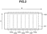
- Fig. 2 is a diagram illustrating the configuration of the recording unit 101 when the area containing the recording unit 101 is viewed from an internal portion of the transfer body 103.
- the recording unit 101 for discharging ink is arranged on the recording apparatus.
- the recording unit 101 includes seven recording heads 102a to 102g for discharging ink of different colors, which are arranged in an X-direction (i.e., rotation direction or scanning direction). Specifically, the recording head 102a discharges cyan ink (C), the recording head 102b discharges magenta ink (M), the recording head 102c discharges yellow ink (Y), the recording head 102d discharges black ink (K), the recording head 102e discharges light-cyan ink (Lc), the recording head 102f discharges light-magenta ink (Lm), and the recording head 102g discharges gray ink (Gy).
- a plurality of recording element arrays including a plurality of recording elements that generates heat energy for discharging ink of each color arrayed in the Y-direction (i.e., array direction) is arranged on each of the recording heads 102a to 102g.
- the transfer body 103 (first recording medium) is arranged on a discharge face side (lower side) of the recording unit 101 included in the recording apparatus. Ink of respective colors are discharged to the transfer body 103 from the recording heads 102a to 102g while the transfer body 103 is being rotated in the X-direction (rotation direction) through a rotation mechanism (not illustrated), so that an image is recorded on the transfer body 103.
- a conveyance roller 106 is arranged to be in contact with the transfer body 103 and rotated in a direction (-X direction) opposite to the rotation direction of the transfer body 103 by a conveyance mechanism (not illustrated). At a contact portion between the transfer body 103 and the conveyance roller 106, an image formed on a surface of the transfer body 103 is transferred to a recording sheet (second recording medium) 105 conveyed by the conveyance mechanism (not illustrated), so that the image is recorded on the recording sheet 105.
- a linear encoder 108 on which a slit is provided at predetermined intervals is attached to a shaft of the transfer body 103. Further, a linear encoder sensor (not illustrated) is arranged at a position at which the linear encoder 108 is detectable. The linear encoder 108 rotates along with rotation of the transfer body 103, and the linear encoder sensor detects respective slits provided on the linear encoder 108, so that a discharge timing of ink discharged from each of the recording heads 102a to 102g is adjusted based on the detection timing.
- the linear encoder 108 may be attached to a position away from the shaft of the transfer body 103.
- a rotary encoder may be arranged on the shaft of the transfer body 103.
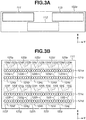
- Figs. 3A and 3B are diagrams illustrating a configuration of the recording head 102a for cyan ink used in the present exemplary embodiment.
- the recording head 102a will be described from among the recording heads 102a to 102g, configurations of the recording heads 102b to 102g other than the recording head 102a are similar to that of the recording head 102a.
- Fig. 3A is a diagram schematically illustrating a heater board arranged on the recording head 102a. Further, Fig. 3B is a diagram schematically illustrating respective members arranged on a heater board 111.
- three heater boards (substrate) 111, 112, and 113 are arranged on the recording head 102a.
- a heating element and a recording element are arranged on each of the heater boards 111, 112, and 113.
- the heating element and the recording element are formed as films on a silicon substrate.
- the heater boards 111, 112, and 113 are arranged in the Y-direction with end portions thereof in the Y-direction partially overlapping with each other.
- discharge port arrays for discharging ink are arranged on each of the heater boards 111, 112, and 113. These four discharge port arrays are arranged in the X-direction (intersecting direction). For example, as illustrated in Fig. 3B , four discharge port arrays 121a, 121b, 121c, and 121d are arranged on the heater board 111.
- discharge ports for discharging ink are arranged in the Y-direction (predetermined direction) to form each of the discharge port arrays 121a, 121b, 121c, and 121d.
- a recording element as an electrothermal conversion element is arranged at a position (an inner position in the vicinity of a discharge port) corresponding to each of the discharge ports. Accordingly, an array of recording elements (recording element array) is formed at a position corresponding to each of the discharge port arrays.
- a driving pulse (voltage) is applied to the recording elements via an electric wiring connected thereto. The recording elements are driven by the driving pulse to generate heat energy, so that discharge operation is executed through respective discharge ports by using the generated thermal energy.
- Temperature sensors (detection elements) 123a to 123j and heating elements (sub-heaters) 124a to 124j are arranged on the heater board 111 in addition to the discharge port arrays 121a to 121d and the recording elements.
- Each of the temperature sensors 123a to 123j is a member for detecting a temperature in a vicinity area
- each of the sub-heaters 124a to 124j is a member for heating a vicinity area and retaining the temperature.
- the heater board 111 is divided into ten heating areas 125a to 125j according to positions on the heater board 111.
- the heating areas 125a to 125e respectively include discharge port portions 122a to 122e consisting of portions of the discharge port arrays 121a and 121b divided in the Y-direction.
- the heating areas 125f to 125j respectively include discharge port portions 122f to 122j consisting of portions of the discharge port arrays 121c and 121b divided in the Y-direction.
- the temperature sensor and the sub-heater are arranged in each heating area of the heater board of the present exemplary embodiment.
- the temperature sensor 123a for detecting a temperature of ink in a vicinity of the discharge port portion 122a and the sub-heater 124a for heating ink in a vicinity of the discharge port portion 122a are arranged in the heating area 125a on the heater board 111.
- the sub-heater 124a is divided into two portions, the two portions are connected with the same wiring, and driving or non-driving of the two portions is performed integrally and consistently. Therefore, the two portions are substantially treated as one sub-heater 124a.
- the temperature sensor and the sub-heater are arranged at each heating area on the heater board, and temperature detection and temperature retention control are executed at each heating area, so that the temperature distribution on the heater board (substrate) can be reduced (i.e., temperature can be uniform).
- the temperature distribution on the heater board (substrate) can be reduced (i.e., temperature can be uniform).
- the temperature of the heating areas 125a to 125c is low whereas the temperature of the heating areas 125d to 125j is approximately the same as the target temperature, only the heating areas 125a to 125c can be heated by driving the sub-heaters 124a to 124c.
- lowering of the temperature in the heating areas 125a to 125c can be suppressed, and a temperature difference within the heater board 111 can be reduced.
- Fig. 4 is a diagram illustrating a configuration of a recording control system in the recording apparatus of the present exemplary embodiment.
- a recording control system relating to the recording head 102a will be described although the recording apparatus of the present exemplary embodiment includes seven recording heads 102a to 102g as illustrated in Figs. 1 and 2 .
- the recording apparatus includes an encoder sensor 301, a dynamic random access memory (DRAM) 302, a read only memory (ROM) 303, and a controller (application specific integrated circuit (ASIC)) 304.
- the recording apparatus further includes the above-described heater boards 111 to 113 and an analog-digital (AD) conversion device 314.
- DRAM dynamic random access memory
- ROM read only memory
- ASIC application specific integrated circuit
- a recording data generation unit 305 a central processing unit (CPU) 306, a discharge timing generation unit 307, a temperature value storage memory 308, a sub-heater driving table storage memory (table storage memory) 313, and data transfer units 310 to 312 are arranged on the controller 304.
- CPU central processing unit
- discharge timing generation unit 307 a discharge timing generation unit 307
- temperature value storage memory 308 a sub-heater driving table storage memory (table storage memory) 313, and data transfer units 310 to 312 are arranged on the controller 304.
- a sub-heater driving table storage memory (table storage memory) 313, and data transfer units 310 to 312 are arranged on the controller 304.
- the CPU 306 reads and executes a program stored in the ROM 303 to control operation of the entire recording apparatus such as driving operation of a driver such as a motor. Further, fixed data necessary for various kinds of operation of the recording apparatus is stored in the ROM 303 in addition to various control programs executed by the CPU 306. For example, a program for executing recording control of the recording apparatus is stored.
- the DRAM 302 is necessary for the CPU 306 to execute a program.
- the DRAM 302 is used as a work area of the CPU 306 or a temporary storage area of various received data, and various setting data may be stored. Further, although only one DRAM 302 is illustrated in Fig. 4 , a plurality of DRAMs may be mounted, or both of a DRAM and a static random access memory (SRAM) may be mounted as a plurality of memories having different access speeds.
- SRAM static random access memory
- the recording data generation unit 305 receives image data from a host (personal computer (PC)) outside the recording apparatus. Then, the recording data generation unit 305 executes color conversion processing or quantization processing on the image data, generates recording data used for discharging ink from the recording head 102a, and stores the generated recording data in the DRAM 302.
- a host personal computer (PC)
- PC personal computer
- the discharge timing generation unit 307 receives position information indicating relative positions of the recording head 102a and the recording medium 103 detected by the encoder sensor 301. Then, based on the position information, the discharge timing generation unit 307 generates discharge timing information indicating a timing of discharging ink from the recording head 102a.
- Three data transfer units 310, 311, and 312 read recording data stored in the DRAM 302 according to the discharge timing generated by the discharge timing generation unit 307. Further, sub-heater driving information generated as described below is also read from a heating control unit 309. Then, each of the data transfer units 310, 311, and 312 transfers the recording data and the sub-heater driving information to each of the heater board 111, 112, and 113 via a wiring substrate.
- Each of the heater boards 111, 112, and 113 uses the transferred recording data to drive the recording elements to discharge ink, and outputs the output values of temperature sensors within the heater board to the AD conversion device 314. Further, in order to reduce the number of signals simultaneously input to the AD conversion device 314, output values of temperature sensors are sequentially input to the AD conversion device 314 one by one from all of the temperature sensors arranged on the heater boards 111, 112, and 113.
- the AD conversion device 314 converts the output values of the temperature sensors into digital values (temperature values), and outputs those temperature values to the heating control unit 309.
- the heating control unit 309 it will take 50 ⁇ s to detect a temperature from one temperature senor.
- the three heater boards 111, 112, and 113 are arranged on the recording head 102a, and ten temperature sensors are arranged on each of the heater boards 111, 112, and 113. Therefore, it will take 1500 ⁇ s (50 ⁇ 3 ⁇ 10) for the heating control unit 309 to update temperature values of all of the temperature sensors.
- the temperature value of one temperature sensor is updated every 1500 ⁇ s.
- the heating control unit 309 stores the temperature values received from the AD conversion device 314 in the temperature value storage memory 308. Then, the heating control unit 309 reads out the latest temperature value stored in the temperature value storage memory 308 according to an input of the discharge timing information, and generates the sub-heater generation information at each heater board based on the heating control table of the heater board previously stored in the sub-heater driving table storage memory 313. As described above, the generated sub-heater driving information is output to the data transfer units 310, 311, and 312.
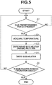
- Fig. 5 is a flowchart of sub-heater heating control executed by the heating control unit 309 and the recording head 102a of the present exemplary embodiment.
- the sub-heater heating control Through the sub-heater heating control, sub-heaters arranged in respective heating areas of the recording heads 102a to 102g are driven to retain the temperature of ink during a recording period, when the recording elements are being driven to cause ink to be discharged from the recording heads 102a to 102g.
- the recording heads 102a to 102h only control with respect to the recording head 102a will be described. However, similar control is also executed with respect to the other recording heads 102b to 102h.
- a target temperature is set to 50°C.
- step S1 the heating control unit 309 determines whether a predetermined period has passed after previous sub-heater heating operation is executed. The processing in step S1 may be omitted if recording operation and sub-heater heating operation have just been started.
- a different time period can be appropriately set as the predetermined period, a period the same as the update interval of the temperature value, i.e., 1500 ⁇ s, is set thereto.
- step S2 the heating control unit 309 reads out the latest stored temperature value from the temperature value storage memory 308. Because reading is executed at each of the temperature sensors, temperature values of ten pieces each of temperature sensors respectively arranged on three heater boards, i.e., temperature values of thirty temperature sensors in total, will be acquired.
- step S3 based on the sub-heater driving table stored in the sub-heater driving table storage memory 313 and the temperature values acquired in step S2, a sub-heater driving pattern for driving the sub-heater is determined as the sub-heater driving information.
- the sub-heater driving table of the present exemplary embodiment directly specifies a correspondence between a temperature and a sub-heater driving pattern indicating a driving timing of the sub-heater.
- the heating control unit 309 refers to the sub-heater driving table and determines the sub-heater driving pattern corresponding to the temperature detected by each of the temperature sensors. A determination method of the sub-heater driving pattern will be described below.
- step S4 the heating control unit 309 drives the sub-heater according to the determined sub-heater driving pattern and retains a temperature of ink in the vicinity of a recording element group belonging to the corresponding heating area.
- step S5 the heating control unit 309 determines whether the sub-heater heating operation has been ended. In the present exemplary embodiment, sub-heater heating operation is ended when recording is ended. If it is determined that sub-heater heating operation has not been ended (i.e., recording has not been ended) (NO in step S5), the processing returns to step S1, and the heating control unit 309 drives the sub-heater according to the sub-heater driving pattern determined in previous step S3 until the predetermined period has passed. Then, when the predetermined period has passed, the processing proceeds to step S2 again, so that the temperature value is updated and similar control processing is continued. If the heating control unit 309 determines that sub-heater heating operation has been ended (YES in step S5), the processing flow illustrated in Fig. 5 is ended.
- Fig. 6 is a diagram illustrating a sub-heater driving table used for the present exemplary embodiment.
- the sub-heater driving table "1" represents output of a driving signal indicating driving of the sub-heater, whereas "0" represents output of a driving signal indicating non-driving of the sub-heater.
- the upper row illustrates a sub-heater driving pattern to be selected when the temperature is less than 50°C
- the lower row illustrates a sub-heater driving pattern to be selected when the temperature is 50°C or more.
- driving signals are output according to passage of time while a reading position is being shifted from left to right every 10 ⁇ s. The reading position returns to the left end after being shifted to the right end, so that the driving signals are output while the reading position is being shifted from left to right sequentially.
- the driving signals are output in the order of 1, 1, 1, 1, 1, 1, 0, 0, 0, and 0 if the temperature is less than 50°C. Accordingly, the sub-heater is driven for the first 50 ⁇ s (corresponding to the first five driving signals represented by "1") and is not driven for the subsequent 50 ⁇ s (corresponding to the first five driving signals represented by "0"). Thereafter, the reading position returns to the left end of the sub-heater driving pattern, so that the sub-heater is driven for the next 50 ⁇ s, and is not driven for the following 50 ⁇ s. As described above, because the sub-heater is driven to a certain extent if the temperature is less than 50°C, the temperature of vicinity ink can be prevented from being lowered.
- the left end of the sub-heater driving pattern in Fig. 6 is specified as a reading start position of the driving signal of all of the ten sub-heaters 124a to 124j arranged on the heater board 111, excessive amount of inrush current will flow into the heater board 111, possibly increasing a load with respect to an electric circuit of the heater board 111 or possibly causing data transmission error due to induction noise.
- the driving signals are output in the order of 1, 1, 1, 1, 1, 1, 0, 0, 0, and 0 with respect to all of the sub-heaters 124a to 124j. Therefore, all of the sub-heaters 124a to 124j in a non-driving state are switched to a driving state at the same timing immediately after the sub-heater heating control is started. If electric current is to be applied to a circuit to which the electric current has not been applied, electric current (inrush current) higher than the electric current applied in its steady state may flow into the circuit.
- a reading start position of the sub-heater driving pattern is set differently at each of the sub-heaters 124a to 124j.
- the driving signals are read from the left end of the sub-heater driving table in Fig. 6 with respect to the sub-heater 124a, whereas the driving signals are read from the right end with respect to the sub-heater 124b.
- different reading start positions of the sub-heater driving table are set for other sub-heaters 124c to 124j.
- the sub-heater driving table is read from the left end with respect to the sub-heater 124a, so that driving signals are output in the order of 1, 1, 1, 1, 1, 0, 0, 0, and 0.
- the sub-heater driving table is read from the right end with respect to the sub-heater 124b, the driving signals are output in the order of 0, 1, 1, 1, 1, 1, 0, 0, 0, and 0.
- the sub-heater driving table is read from the fifth position from the right end, the driving signals are output in the order of 0, 0, 0, 0, 0, 1, 1, 1, 1, and 1.
- the output orders of the driving signals are offset with each other. Accordingly, a timing at which the sub-heater is switched from a non-driving state to a driving state, i.e., a timing at which inrush current occurs, can be set differently at each of the sub-heaters.
- a load of the electric circuit can be reduced, or a data transmission error can be reduced by suppressing occurrence of induction noise.
- Fig. 7 is a diagram schematically illustrating actual driving timings of the sub-heaters 124a to 124j when the reading start position of the sub-heater driving table is set differently at each of the sub-heaters 124a to 124j.
- driving timings will be described with respect to the case where each of the temperature sensors 123a to 123j constantly detects the temperature lower than 50°C.
- the sub-heater 124a because reading is started from the left end, the driving signals are input in the order of 1, 1, 1, 1, 1, 1, 0, 0, 0, and 0. Accordingly, the sub-heater 124a is driven at the first to the fifth input timings of the driving signals. Then, the sub-heater 124a is not driven at the sixth to the tenth input timings of the driving signals. Then, the sub-heater 124a is driven again at the eleventh input timing of the driving signal. Accordingly, the sub-heater 124a is switched from a non-driving state to a driving state at the input timings of the first and the eleventh driving signals, which are the timings at which inrush current occurs.
- the sub-heater 124b Because reading is started from the right end, the driving signals are input in the order of 0, 1, 1, 1, 1, 1, 0, 0, and 0. Accordingly, the sub-heater 124b is not driven at the input timing of the first driving signal, and driven at the input timings of the second to the sixth driving signals. Then, the sub-heater 124b is switched to the non-driving state at the input timing of the seventh driving signal, and switched to the driving state at the input timing of the twelfth driving signal. As described above, with respect to the sub-heater 124b, there is a risk in which inrush current occurs at the input timings of the second and the twelfth driving signals.
- the sub-heater 124f because reading is started from the fifth position from the right end, the driving signals are input in the order of 0, 0, 0, 0, 0, 1, 1, 1, 1, and 1. Accordingly, the sub-heater 124f is not driven at the input timings of the first to the fifth driving signals and switched to the driving state at the input timing of the sixth driving signal, and further switched to the non-driving state at the input timing of the eleventh driving signal. Accordingly, with respect to the sub-heater 124f, there is a risk in which inrush current occurs at the input timing of the sixth driving signal.
- a timing at which inrush current occurs i.e., a timing at which the sub-heater is switched from a non-driving state to a driving state, is set differently at each of the sub-heaters. Accordingly, as described above, an effect of reducing a load of the electric circuit or an effect of suppressing induction noise can be acquired.
- sub-heater heating control is constantly executed at the same intensity.
- sub-heater heating control is executed at different intensity according to a difference between a temperature detected by the temperature sensor and the target temperature.
- the sub-heater is driven if the temperature detected by the temperature sensor is lower than the target temperature, and the sub-heater is not driven if the detected temperature is higher than the target temperature.
- favorable driving intensity of the sub-heater i.e., the favorable heating amount
- the target temperature is 50°C
- heating does not have to be executed so intensively if the detected temperature is 45°C.
- the target temperature it is preferable that the target temperature be achieved as quickly as possible by executing heating at a certain degree of intensity.
- the sub-heater driving table storage memory 313 of the present exemplary embodiment stores the sub-heater driving tables of two types, i.e., a first sub-heater driving table in which a correspondence between a temperature difference and a sub-heater driving intensity is specified, and a second sub-heater driving table in which a correspondence between the sub-heater driving intensity and the sub-heater driving pattern is specified.
- the sub-heater heating control using two types of sub-heater driving tables will be described below in detail.
- Fig. 8 is a flowchart of sub-heater heating control executed by the heating control unit 309 and the recording head 102a of the present exemplary embodiment.
- the recording heads 102a to 102h only control with respect to the recording head 102a will be described. However, similar control is also executed with respect to the other recording heads 102b to 102h.
- steps S11 and S12 in Fig. 8 is similar to the processing in steps S1 and S2 illustrated in Fig. 5 , so that description thereof will be omitted.
- step S13 a difference (temperature difference) between a predetermined target temperature and a temperature (detected temperature) detected at each of the temperature sensors 123a to 123j acquired in step S12 is calculated.
- This difference is calculated by subtracting the detected temperature from the target temperature. Accordingly, the detected temperature is higher than the target temperature if a negative value is acquired as a difference, and the detected temperature is lower than the target temperature if a positive value is acquired as a difference.
- step S14 sub-heater driving intensity is determined based on the first sub-heater driving table stored in the sub-heater driving table storage memory 313 and the temperature difference at each temperature sensor calculated in step S13. As described above, the correspondence between the temperature difference and the sub-heater driving intensity is specified in the first sub-heater driving table. The sub-heater driving intensity corresponding to the temperature difference calculated in step S13 is determined with reference to the first sub-heater driving table.
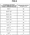
- Fig. 9 is a diagram illustrating the first sub-heater driving table used for the present exemplary embodiment.
- the intensity (heating amount) is set as 100%. Accordingly, for example, the intensity (heating amount) is 50% if the driving signal indicating driving of the sub-heater is received at half the number of timings at which the sub-heater driving signal can be input while the driving signal indicating non-driving of the sub-heater is received at another half the number thereof.
- a correspondence between the temperature difference and the sub-heater driving intensity is specified to make the sub-heater driving intensity be greater when the temperature difference is greater. Accordingly, by using the first sub-heater driving table, heating can be executed more intensively if the temperature difference is greater, i.e., the detected temperature is much lower than the target temperature.
- step S15 the sub-heater driving pattern is determined based on the second sub-heater driving table stored in the sub-heater driving table storage memory 313 and the sub-heater driving intensity determined in step S14. As described above, a correspondence between the sub-heater driving intensity and the sub-heater driving pattern is specified in the second sub-heater driving table. The sub-heater driving pattern corresponding to the sub-heater driving intensity determined in step S14 is determined with reference to the second sub-heater driving table.
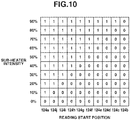
- Fig. 10 is a diagram illustrating the second sub-heater driving table used for the present exemplary embodiment.
- “ 1 " represents output of the sub-heater driving signal indicating driving
- "0" represents output of the sub-heater driving signal indicating non-driving.
- ten rows in the vertical direction indicate driving intensity of the sub-heater.
- the sub-heater driving signals are output according to passage of time while a reading position is being shifted from left to right, and the reading position returns to the left end after being shifted to the right end, so that the sub-heater driving signals are output while the reading position is being shifted from left to right again.
- the sub-heater driving pattern is determined to make the number of sub-heater driving signals indicating driving (represented by "1") be changed according to the sub-heater driving intensity.
- the number of sub-heater driving signals indicating driving (represented by "1"), i.e., a number of driving times of the sub-heater, is greater if the sub-heater driving intensity is higher.
- respective driving signals of 1, 1, 1, 1, 1, 1, 1, 1, 1, and 0 are specified from the left end of the second sub-heater driving table. Accordingly, nine driving signals indicate driving of the sub-heater.
- respective driving signals of 1, 1, 1, 1, 1, 0, 0, 0, and 0 are specified from the left end of the second sub-heater driving table. Accordingly, five driving signals indicate driving of the sub-heater.
- sub-heater driving intensity is 0%
- respective driving signals of 0, 0, 0, 0, 0, 0, 0, 0, and 0 are specified from the left end of the second sub-heater driving table. Accordingly, none of the driving signals indicates driving of the sub-heater.
- the number of driving times of the sub-heater can be increased if the sub-heater driving intensity is higher.
- a reading start position of the sub-heater driving table is set differently with respect to the ten sub-heaters 124a to 124j arranged on the heater board 111. Details of the reading start positions for the sub-heaters 124a to 124j are illustrated in Fig. 10 .
- the driving signals are output in the order of 1, 1, 1, 1, 1, 1, 1, 1, 1, 1, and 0 if the sub-heater driving intensity is 90%. Further, if the sub-heater driving intensity is 50%, the driving signals are output in the order of 1, 1, 1, 1, 1, 0, 0, 0, and 0.
- the driving signals are output in the order of 0, 1, 1, 1, 1, 1, 1, 1, 1, and 1 if the sub-heater driving intensity is 90%. Further, if the sub-heater driving intensity is 50%, the driving signals are output in the order of 0, 1, 1, 1, 1, 1, 0, 0, and 0.
- the output orders of the driving signals are also offset with each other. Accordingly, a timing at which the sub-heater is switched from a non-driving state to a driving state, i.e., a timing at which inrush current occurs, can be set differently at each of the sub-heaters.
- a load of the electric circuit can be reduced, or a data transmission error can be reduced by suppressing occurrence of induction noise.
- step S13 the temperature difference is calculated as 13°C at each of the temperature sensors 123a to 123j.
- step S14 with reference to the first sub-heater driving table, the sub-heater driving intensity is determined as 50% because the temperature difference falls within a range of 10°C or more and less than 15°C at each of the temperature sensors 123a to 123j. Accordingly, in step S15, with reference to the second sub-heater driving table, the sub-heater driving pattern corresponding to the sub-heater driving intensity of 50% is read out.
- the driving signals are output in the order of 1, 1, 1, 1, 1, 0, 0, 0, and 0.
- the driving signals are output in the order of 0, 1, 1, 1, 1, 1, 0, 0, and 0.
- the driving signals are output in respective orders with reference to the second sub-heater driving table. Accordingly, actual driving timings of the respective sub-heaters are similar to those illustrated in Fig. 7 in the first exemplary embodiment.
- a timing at which inrush current occurs i.e., a timing at which the sub-heater is switched from a non-driving state to a driving state, can be set differently at each of the sub-heaters when the temperature sensors 123a to 123j detect the temperature of 37°C.
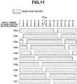
- Fig. 11 is a diagram illustrating driving timings of respective sub-heaters when each of the temperature sensors 123a to 123j detects the temperature of 17°C.
- the temperature difference is detected as 33°C at each of the temperature sensors 123a to 123j.
- the sub-heater driving intensity is determined as 90% because the temperature difference falls within a range of 30°C or more at each of the temperature sensors 123a to 123j.
- the sub-heater driving pattern corresponding to the sub-heater driving intensity of 90% is read out.
- the driving signals are output in the order of 1, 1, 1, 1, 1, 1, 1, 1, 1, and 0.
- the driving signals are output in the order of 0, 1, 1, 1, 1, 1, 1, 1, 1, 1, and 1.
- the driving signals are output in respective orders with reference to the second sub-heater driving table. Accordingly, actual driving timings of respective sub-heaters are as illustrated in Fig. 11 .
- a timing at which inrush current occurs i.e., a timing at which the sub-heater is switched from a non-driving state to a driving state, can be also set differently at each of the sub-heaters when the temperature sensors 123a to 123j detect the temperature of 17°C.
- an effect of reducing a load of the electric circuit or an effect of suppressing induction noise can be acquired while heating is expedited by increasing the driving intensity when the temperature difference between the detected temperature and the target temperature is greater.
- sub-heater driving tables of two types i.e., the first sub-heater driving table in which a correspondence between the temperature difference and the sub-heater driving intensity is specified and the second sub-heater driving table in which a correspondence between the sub-heater driving intensity and the sub-heater driving pattern is specified are used.
- a correspondence between the temperature difference and the sub-heater driving pattern is not specified directly but specified indirectly by the first and the second sub-heater driving tables.
- the present invention is not limited to the above.
- an effect similar to the effect of the present exemplary embodiment can be acquired by using only one type of sub-heater driving pattern in which a correspondence between the temperature difference and the sub-heater driving pattern is directly specified as illustrated in Fig. 12 .
- a reading start position of the sub-heater driving table (i.e., second sub-heater driving table) is set differently at each of the sub-heaters arranged on one heater board.
- the same reading start position of the sub-heater driving table is specified with respect to a part of the sub-heaters.
- sub-heater heating control is executed according to the flowchart illustrated in Fig. 5 .
- the sub-heater driving table used in step S3 is different from that of the first exemplary embodiment.
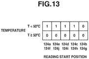
- Fig. 13 is a diagram illustrating a sub-heater driving table used for the present exemplary embodiment.
- the sub-heater driving table "1" represents output of a driving signal indicating driving of the sub-heater, whereas "0" represents output of a driving signal indicating non-driving of the sub-heater.
- the upper row illustrates a sub-heater driving pattern of the driving signals to be output when the temperature is less than 50°C
- the lower row illustrates a sub-heater driving pattern of the driving signals to be output when the temperature is 50°C or more.
- the driving signals are output according to passage of time while the reading position is being shifted from left to right every 10 ⁇ s, and the reading position returns to the left end after being shifted to the right end, so that the driving signals are output while the reading position is being shifted from left to right sequentially.
- the same reading start position of the sub-heater driving pattern is specified with respect to a pair of sub-heaters 124a and 124f, so that the sub-heater driving table is read from the left end at both of the sub-heaters 124a and 124f. Further, the same reading start position of the sub-heater driving pattern is specified with respect to a pair of sub-heaters 124b and 124g, so that the sub-heater driving table is read from the right end at both of the sub-heaters 124b and 124g.
- the same reading start position of the sub-heater driving pattern is specified with respect to a pair of sub-heaters 124c and 124h, a pair of sub-heaters 124d and 124i, or a pair of sub-heaters 124e and 124j.
- the driving signals are output in the order of 1, 1, 1, 1, and 0 with respect to the sub-heaters 124a and 124f. Further, the driving signals are output in the order of 0, 1, 1, 1, and 1 with respect to the sub-heaters 124b and 124g.
- Fig. 14 is a diagram illustrating driving timings of respective sub-heaters when the temperature sensors 123a to 123j detect the temperature less than 50°C.
- timings at which inrush current occurs i.e., timings at which the sub-heaters are switched from a non-driving state to a driving state, are superimposed with each other.
- temperature information detected by the temperature sensor is updated every 1500 ⁇ s, this period may be changed as appropriate.
- a temperature detected prior to that timing may be also used. For example, if one temperature is detected from a temperature sensor at one timing, a moving average between the one temperature and a temperature detected at a timing just before the one timing (e.g., 1500 ⁇ s before) may be calculated to be used for the heating control. If the above-described average temperature is used, there is a risk that the temperature may be deviated from the precise temperature detected at each timing. However, in a case where deviations occur in measurement of the detected temperature due to an influence of noise, deviations caused by the influence of noise can be reduced to some extent.
- the same sub-heater driving table is used for the respective sub-heaters, and superimposition of inrush current is suppressed by changing the reading start position of the sub-heater driving table.
- the present invention is not limited thereto.
- different sub-heater driving tables may be used for the respective sub-heaters.
- the effect similar to the effect acquired from the other exemplary embodiments can be acquired if the respective sub-heater driving tables are specified to make the timings at which the sub-heaters are switched from a non-driving state to a driving state be different from each other.
- a reading start position of the sub-heater driving pattern is always set differently at each of the sub-heaters, the present invention is not limited thereto. For example, it may be determined whether timings at which inrush current is increased (i.e., timings at which the sub-heaters are switched from a non-driving state to a driving state) are superimposed with each other, and the reading start position may be switched to the reading start position described in the above-described exemplary embodiment only when it is determined that the timings are superimposed with each other.
- signals indicating driving of the sub-heater and signals indicating non-driving thereof are output respectively in a consecutive manner.
- five driving signals indicating driving are output consecutively from the left end.
- five driving signals indicating non-driving are consecutively output up to the right end.
- the driving signals indicating driving and the driving signals indicating non-driving do not always have to be output consecutively as described in the respective exemplary embodiments, the driving signals can be output consecutively to some extent.
- a driving signal indicating driving and a driving signal indicating non-driving are alternately output, even if a reading start position is set differently at each of the sub-heaters, timings at which a non-driving state is switched to a driving state are superimposed to a certain extent (approximately half the number of sub-heaters).
- the driving signals indicating driving and the driving signals indicating non-driving can be output respectively in a consecutive manner.
- ink is applied to the transfer body (first recording medium) from the recording head
- recording is performed on a recording sheet (second recording medium) by transferring an image formed on the transfer body to the recording sheet.
- the present invention is not limited thereto.
- ink may be directly applied to a recording sheet from the recording head.
- a recording head having a length longer than a width of a recording medium is used, the present invention is not limited thereto.
- recording operation of making the recording head discharge ink while scanning in a direction intersecting with an array direction of discharge ports and conveyance operation of conveying a recording medium in the array direction between the scans may be executed repeatedly, so that recording with respect to the recording medium may be completed by a plurality of times of scanning (moving) operation.
- a negative effect caused by superimposition of inrush current can be suppressed in a case where a recording head having a plurality of heating elements arranged on a same substrate is to be used.
Landscapes
- Ink Jet (AREA)
- Particle Formation And Scattering Control In Inkjet Printers (AREA)
Applications Claiming Priority (1)
| Application Number | Priority Date | Filing Date | Title |
|---|---|---|---|
| JP2017074679A JP6971609B2 (ja) | 2017-04-04 | 2017-04-04 | 記録装置および記録方法 |
Publications (2)
| Publication Number | Publication Date |
|---|---|
| EP3385080A1 EP3385080A1 (en) | 2018-10-10 |
| EP3385080B1 true EP3385080B1 (en) | 2020-11-25 |
Family
ID=61832414
Family Applications (1)
| Application Number | Title | Priority Date | Filing Date |
|---|---|---|---|
| EP18164619.1A Active EP3385080B1 (en) | 2017-04-04 | 2018-03-28 | Recording apparatus and recording method |
Country Status (4)
| Country | Link |
|---|---|
| US (1) | US10576737B2 (enExample) |
| EP (1) | EP3385080B1 (enExample) |
| JP (1) | JP6971609B2 (enExample) |
| CN (1) | CN108688324B (enExample) |
Families Citing this family (1)
| Publication number | Priority date | Publication date | Assignee | Title |
|---|---|---|---|---|
| WO2022128924A1 (en) | 2020-12-14 | 2022-06-23 | Neos S.R.L. | Head-carrier bar for a digital printing device, digital printing device comprising said head-carrier device and method for controlling the positioning of print heads assembled on a head-carrier bar |
Family Cites Families (21)
| Publication number | Priority date | Publication date | Assignee | Title |
|---|---|---|---|---|
| US4791435A (en) * | 1987-07-23 | 1988-12-13 | Hewlett-Packard Company | Thermal inkjet printhead temperature control |
| JPH035151A (ja) | 1989-06-02 | 1991-01-10 | Canon Inc | 液体噴射記録ヘッド |
| US4980702A (en) * | 1989-12-28 | 1990-12-25 | Xerox Corporation | Temperature control for an ink jet printhead |
| US5223853A (en) * | 1992-02-24 | 1993-06-29 | Xerox Corporation | Electronic spot size control in a thermal ink jet printer |
| US5623297A (en) * | 1993-07-07 | 1997-04-22 | Intermec Corporation | Method and apparatus for controlling a thermal printhead |
| US5497174A (en) * | 1994-03-11 | 1996-03-05 | Xerox Corporation | Voltage drop correction for ink jet printer |
| US6276776B1 (en) * | 1996-12-17 | 2001-08-21 | Canon Kabushiki Kaisha | Ink-jet printer and temperature control method of recording head |
| JP3486547B2 (ja) * | 1996-12-17 | 2004-01-13 | キヤノン株式会社 | インクジェットプリンタと、記録ヘッドの温度制御方法 |
| JP2005212454A (ja) | 2004-02-02 | 2005-08-11 | Mitsubishi Electric Corp | サーマルプリンタの高画質化装置及びサーマルプリンタの高画質化方法 |
| US7488056B2 (en) | 2004-04-19 | 2009-02-10 | Hewlett--Packard Development Company, L.P. | Fluid ejection device |
| US7686411B2 (en) * | 2006-04-14 | 2010-03-30 | Canon Kabushiki Kaisha | Recording apparatus |
| CN201046623Y (zh) * | 2007-06-19 | 2008-04-16 | 浙江工正科技发展有限公司 | 喷头加热装置 |
| US20090160898A1 (en) * | 2007-12-20 | 2009-06-25 | Steven Wayne Bergstedt | Method and apparatus for controlling non-nucleating heating in a fluid ejection device |
| US8172369B2 (en) * | 2008-12-30 | 2012-05-08 | Lexmark International, Inc. | Inkjet printhead substrate with distributed heater elements |
| JP5473748B2 (ja) * | 2010-04-23 | 2014-04-16 | キヤノン株式会社 | インクジェット記録装置 |
| US9044942B2 (en) * | 2010-09-30 | 2015-06-02 | Hewlett-Packard Development Company, L.P. | Thermal sensing fluid ejection assembly and method |
| WO2013019181A1 (en) * | 2011-07-29 | 2013-02-07 | Hewlett-Packard Development Company, L.P. | Heater controller and method thereof |
| JP6083979B2 (ja) * | 2012-08-31 | 2017-02-22 | キヤノン株式会社 | 記録ヘッド |
| JP6274741B2 (ja) * | 2013-04-03 | 2018-02-07 | キヤノン株式会社 | 液体吐出ヘッド用基板、液体吐出ヘッドおよび液体吐出ヘッドユニット |
| JP6324230B2 (ja) * | 2014-06-18 | 2018-05-16 | キヤノン株式会社 | インクジェット記録装置、インクジェット記録方法およびプログラム |
| EP3411237B1 (en) * | 2016-02-05 | 2020-09-09 | Hewlett-Packard Development Company, L.P. | Printheads |
-
2017
- 2017-04-04 JP JP2017074679A patent/JP6971609B2/ja active Active
-
2018
- 2018-03-28 EP EP18164619.1A patent/EP3385080B1/en active Active
- 2018-03-28 US US15/938,515 patent/US10576737B2/en active Active
- 2018-04-02 CN CN201810281516.6A patent/CN108688324B/zh active Active
Non-Patent Citations (1)
| Title |
|---|
| None * |
Also Published As
| Publication number | Publication date |
|---|---|
| JP2018176448A (ja) | 2018-11-15 |
| US20180281399A1 (en) | 2018-10-04 |
| US10576737B2 (en) | 2020-03-03 |
| CN108688324A (zh) | 2018-10-23 |
| EP3385080A1 (en) | 2018-10-10 |
| JP6971609B2 (ja) | 2021-11-24 |
| CN108688324B (zh) | 2020-04-17 |
Similar Documents
| Publication | Publication Date | Title |
|---|---|---|
| US7216948B2 (en) | Image forming apparatus | |
| JP2012091528A (ja) | インクジェット記録装置及びインクジェット記録制御方法 | |
| EP3385080B1 (en) | Recording apparatus and recording method | |
| JP6360410B2 (ja) | 記録装置及びその駆動方法 | |
| JP6135047B2 (ja) | 印刷制御装置、及び、プログラム | |
| EP2584499B1 (en) | Image forming apparatus and image forming method | |
| JP5882660B2 (ja) | 記録装置 | |
| US6626517B2 (en) | Printing apparatus and printing method | |
| JP4567354B2 (ja) | 画像形成装置 | |
| US7850268B2 (en) | Recording method and recording apparatus | |
| JP6786344B2 (ja) | 記録装置および制御方法 | |
| US20100321433A1 (en) | Multi-chip printhead array with reduced nozzle offset | |
| CN105555540B (zh) | 打印 | |
| JP2018199307A (ja) | 記録装置および記録方法 | |
| JP6163705B2 (ja) | 印刷制御装置、及び、プログラム | |
| US7306306B2 (en) | Inkjet recording method and inkjet recording apparatus | |
| JP2007038653A (ja) | 記録方法、記録装置 | |
| JP2010158817A (ja) | 記録装置および記録ヘッド | |
| US9056456B2 (en) | Recording apparatus and recording method | |
| JP5740359B2 (ja) | プリンタと、その制御回路 | |
| JP6896395B2 (ja) | 記録装置および記録ヘッドの駆動方法 | |
| JP2024088143A (ja) | 情報処理装置、情報処理方法、およびプログラム | |
| JP6574666B2 (ja) | 記録装置 | |
| JP2008023921A (ja) | ラインプリンタ | |
| JP6690370B2 (ja) | 印刷装置 |
Legal Events
| Date | Code | Title | Description |
|---|---|---|---|
| PUAI | Public reference made under article 153(3) epc to a published international application that has entered the european phase |
Free format text: ORIGINAL CODE: 0009012 |
|
| STAA | Information on the status of an ep patent application or granted ep patent |
Free format text: STATUS: THE APPLICATION HAS BEEN PUBLISHED |
|
| AK | Designated contracting states |
Kind code of ref document: A1 Designated state(s): AL AT BE BG CH CY CZ DE DK EE ES FI FR GB GR HR HU IE IS IT LI LT LU LV MC MK MT NL NO PL PT RO RS SE SI SK SM TR |
|
| AX | Request for extension of the european patent |
Extension state: BA ME |
|
| STAA | Information on the status of an ep patent application or granted ep patent |
Free format text: STATUS: REQUEST FOR EXAMINATION WAS MADE |
|
| 17P | Request for examination filed |
Effective date: 20190410 |
|
| RBV | Designated contracting states (corrected) |
Designated state(s): AL AT BE BG CH CY CZ DE DK EE ES FI FR GB GR HR HU IE IS IT LI LT LU LV MC MK MT NL NO PL PT RO RS SE SI SK SM TR |
|
| GRAP | Despatch of communication of intention to grant a patent |
Free format text: ORIGINAL CODE: EPIDOSNIGR1 |
|
| STAA | Information on the status of an ep patent application or granted ep patent |
Free format text: STATUS: GRANT OF PATENT IS INTENDED |
|
| INTG | Intention to grant announced |
Effective date: 20200618 |
|
| GRAS | Grant fee paid |
Free format text: ORIGINAL CODE: EPIDOSNIGR3 |
|
| GRAA | (expected) grant |
Free format text: ORIGINAL CODE: 0009210 |
|
| STAA | Information on the status of an ep patent application or granted ep patent |
Free format text: STATUS: THE PATENT HAS BEEN GRANTED |
|
| AK | Designated contracting states |
Kind code of ref document: B1 Designated state(s): AL AT BE BG CH CY CZ DE DK EE ES FI FR GB GR HR HU IE IS IT LI LT LU LV MC MK MT NL NO PL PT RO RS SE SI SK SM TR |
|
| REG | Reference to a national code |
Ref country code: GB Ref legal event code: FG4D |
|
| REG | Reference to a national code |
Ref country code: CH Ref legal event code: EP |
|
| REG | Reference to a national code |
Ref country code: AT Ref legal event code: REF Ref document number: 1337842 Country of ref document: AT Kind code of ref document: T Effective date: 20201215 |
|
| REG | Reference to a national code |
Ref country code: DE Ref legal event code: R096 Ref document number: 602018009986 Country of ref document: DE |
|
| REG | Reference to a national code |
Ref country code: IE Ref legal event code: FG4D |
|
| REG | Reference to a national code |
Ref country code: AT Ref legal event code: MK05 Ref document number: 1337842 Country of ref document: AT Kind code of ref document: T Effective date: 20201125 |
|
| REG | Reference to a national code |
Ref country code: NL Ref legal event code: MP Effective date: 20201125 |
|
| PG25 | Lapsed in a contracting state [announced via postgrant information from national office to epo] |
Ref country code: FI Free format text: LAPSE BECAUSE OF FAILURE TO SUBMIT A TRANSLATION OF THE DESCRIPTION OR TO PAY THE FEE WITHIN THE PRESCRIBED TIME-LIMIT Effective date: 20201125 Ref country code: PT Free format text: LAPSE BECAUSE OF FAILURE TO SUBMIT A TRANSLATION OF THE DESCRIPTION OR TO PAY THE FEE WITHIN THE PRESCRIBED TIME-LIMIT Effective date: 20210325 Ref country code: RS Free format text: LAPSE BECAUSE OF FAILURE TO SUBMIT A TRANSLATION OF THE DESCRIPTION OR TO PAY THE FEE WITHIN THE PRESCRIBED TIME-LIMIT Effective date: 20201125 Ref country code: NO Free format text: LAPSE BECAUSE OF FAILURE TO SUBMIT A TRANSLATION OF THE DESCRIPTION OR TO PAY THE FEE WITHIN THE PRESCRIBED TIME-LIMIT Effective date: 20210225 Ref country code: GR Free format text: LAPSE BECAUSE OF FAILURE TO SUBMIT A TRANSLATION OF THE DESCRIPTION OR TO PAY THE FEE WITHIN THE PRESCRIBED TIME-LIMIT Effective date: 20210226 |
|
| PG25 | Lapsed in a contracting state [announced via postgrant information from national office to epo] |
Ref country code: AT Free format text: LAPSE BECAUSE OF FAILURE TO SUBMIT A TRANSLATION OF THE DESCRIPTION OR TO PAY THE FEE WITHIN THE PRESCRIBED TIME-LIMIT Effective date: 20201125 Ref country code: IS Free format text: LAPSE BECAUSE OF FAILURE TO SUBMIT A TRANSLATION OF THE DESCRIPTION OR TO PAY THE FEE WITHIN THE PRESCRIBED TIME-LIMIT Effective date: 20210325 Ref country code: PL Free format text: LAPSE BECAUSE OF FAILURE TO SUBMIT A TRANSLATION OF THE DESCRIPTION OR TO PAY THE FEE WITHIN THE PRESCRIBED TIME-LIMIT Effective date: 20201125 Ref country code: LV Free format text: LAPSE BECAUSE OF FAILURE TO SUBMIT A TRANSLATION OF THE DESCRIPTION OR TO PAY THE FEE WITHIN THE PRESCRIBED TIME-LIMIT Effective date: 20201125 Ref country code: SE Free format text: LAPSE BECAUSE OF FAILURE TO SUBMIT A TRANSLATION OF THE DESCRIPTION OR TO PAY THE FEE WITHIN THE PRESCRIBED TIME-LIMIT Effective date: 20201125 Ref country code: BG Free format text: LAPSE BECAUSE OF FAILURE TO SUBMIT A TRANSLATION OF THE DESCRIPTION OR TO PAY THE FEE WITHIN THE PRESCRIBED TIME-LIMIT Effective date: 20210225 |
|
| REG | Reference to a national code |
Ref country code: LT Ref legal event code: MG9D |
|
| PG25 | Lapsed in a contracting state [announced via postgrant information from national office to epo] |
Ref country code: HR Free format text: LAPSE BECAUSE OF FAILURE TO SUBMIT A TRANSLATION OF THE DESCRIPTION OR TO PAY THE FEE WITHIN THE PRESCRIBED TIME-LIMIT Effective date: 20201125 |
|
| PG25 | Lapsed in a contracting state [announced via postgrant information from national office to epo] |
Ref country code: RO Free format text: LAPSE BECAUSE OF FAILURE TO SUBMIT A TRANSLATION OF THE DESCRIPTION OR TO PAY THE FEE WITHIN THE PRESCRIBED TIME-LIMIT Effective date: 20201125 Ref country code: SK Free format text: LAPSE BECAUSE OF FAILURE TO SUBMIT A TRANSLATION OF THE DESCRIPTION OR TO PAY THE FEE WITHIN THE PRESCRIBED TIME-LIMIT Effective date: 20201125 Ref country code: LT Free format text: LAPSE BECAUSE OF FAILURE TO SUBMIT A TRANSLATION OF THE DESCRIPTION OR TO PAY THE FEE WITHIN THE PRESCRIBED TIME-LIMIT Effective date: 20201125 Ref country code: CZ Free format text: LAPSE BECAUSE OF FAILURE TO SUBMIT A TRANSLATION OF THE DESCRIPTION OR TO PAY THE FEE WITHIN THE PRESCRIBED TIME-LIMIT Effective date: 20201125 Ref country code: EE Free format text: LAPSE BECAUSE OF FAILURE TO SUBMIT A TRANSLATION OF THE DESCRIPTION OR TO PAY THE FEE WITHIN THE PRESCRIBED TIME-LIMIT Effective date: 20201125 Ref country code: SM Free format text: LAPSE BECAUSE OF FAILURE TO SUBMIT A TRANSLATION OF THE DESCRIPTION OR TO PAY THE FEE WITHIN THE PRESCRIBED TIME-LIMIT Effective date: 20201125 |
|
| REG | Reference to a national code |
Ref country code: DE Ref legal event code: R097 Ref document number: 602018009986 Country of ref document: DE |
|
| PG25 | Lapsed in a contracting state [announced via postgrant information from national office to epo] |
Ref country code: DK Free format text: LAPSE BECAUSE OF FAILURE TO SUBMIT A TRANSLATION OF THE DESCRIPTION OR TO PAY THE FEE WITHIN THE PRESCRIBED TIME-LIMIT Effective date: 20201125 |
|
| PLBE | No opposition filed within time limit |
Free format text: ORIGINAL CODE: 0009261 |
|
| STAA | Information on the status of an ep patent application or granted ep patent |
Free format text: STATUS: NO OPPOSITION FILED WITHIN TIME LIMIT |
|
| PG25 | Lapsed in a contracting state [announced via postgrant information from national office to epo] |
Ref country code: IT Free format text: LAPSE BECAUSE OF FAILURE TO SUBMIT A TRANSLATION OF THE DESCRIPTION OR TO PAY THE FEE WITHIN THE PRESCRIBED TIME-LIMIT Effective date: 20201125 Ref country code: MC Free format text: LAPSE BECAUSE OF FAILURE TO SUBMIT A TRANSLATION OF THE DESCRIPTION OR TO PAY THE FEE WITHIN THE PRESCRIBED TIME-LIMIT Effective date: 20201125 Ref country code: AL Free format text: LAPSE BECAUSE OF FAILURE TO SUBMIT A TRANSLATION OF THE DESCRIPTION OR TO PAY THE FEE WITHIN THE PRESCRIBED TIME-LIMIT Effective date: 20201125 Ref country code: NL Free format text: LAPSE BECAUSE OF FAILURE TO SUBMIT A TRANSLATION OF THE DESCRIPTION OR TO PAY THE FEE WITHIN THE PRESCRIBED TIME-LIMIT Effective date: 20201125 |
|
| REG | Reference to a national code |
Ref country code: CH Ref legal event code: PL |
|
| 26N | No opposition filed |
Effective date: 20210826 |
|
| PG25 | Lapsed in a contracting state [announced via postgrant information from national office to epo] |
Ref country code: SI Free format text: LAPSE BECAUSE OF FAILURE TO SUBMIT A TRANSLATION OF THE DESCRIPTION OR TO PAY THE FEE WITHIN THE PRESCRIBED TIME-LIMIT Effective date: 20201125 |
|
| REG | Reference to a national code |
Ref country code: BE Ref legal event code: MM Effective date: 20210331 |
|
| PG25 | Lapsed in a contracting state [announced via postgrant information from national office to epo] |
Ref country code: ES Free format text: LAPSE BECAUSE OF FAILURE TO SUBMIT A TRANSLATION OF THE DESCRIPTION OR TO PAY THE FEE WITHIN THE PRESCRIBED TIME-LIMIT Effective date: 20201125 Ref country code: FR Free format text: LAPSE BECAUSE OF NON-PAYMENT OF DUE FEES Effective date: 20210331 Ref country code: CH Free format text: LAPSE BECAUSE OF NON-PAYMENT OF DUE FEES Effective date: 20210331 Ref country code: LU Free format text: LAPSE BECAUSE OF NON-PAYMENT OF DUE FEES Effective date: 20210328 Ref country code: IE Free format text: LAPSE BECAUSE OF NON-PAYMENT OF DUE FEES Effective date: 20210328 Ref country code: LI Free format text: LAPSE BECAUSE OF NON-PAYMENT OF DUE FEES Effective date: 20210331 |
|
| PG25 | Lapsed in a contracting state [announced via postgrant information from national office to epo] |
Ref country code: IS Free format text: LAPSE BECAUSE OF FAILURE TO SUBMIT A TRANSLATION OF THE DESCRIPTION OR TO PAY THE FEE WITHIN THE PRESCRIBED TIME-LIMIT Effective date: 20210325 |
|
| PG25 | Lapsed in a contracting state [announced via postgrant information from national office to epo] |
Ref country code: BE Free format text: LAPSE BECAUSE OF NON-PAYMENT OF DUE FEES Effective date: 20210331 |
|
| GBPC | Gb: european patent ceased through non-payment of renewal fee |
Effective date: 20220328 |
|
| PG25 | Lapsed in a contracting state [announced via postgrant information from national office to epo] |
Ref country code: GB Free format text: LAPSE BECAUSE OF NON-PAYMENT OF DUE FEES Effective date: 20220328 |
|
| PG25 | Lapsed in a contracting state [announced via postgrant information from national office to epo] |
Ref country code: CY Free format text: LAPSE BECAUSE OF FAILURE TO SUBMIT A TRANSLATION OF THE DESCRIPTION OR TO PAY THE FEE WITHIN THE PRESCRIBED TIME-LIMIT Effective date: 20201125 |
|
| PG25 | Lapsed in a contracting state [announced via postgrant information from national office to epo] |
Ref country code: HU Free format text: LAPSE BECAUSE OF FAILURE TO SUBMIT A TRANSLATION OF THE DESCRIPTION OR TO PAY THE FEE WITHIN THE PRESCRIBED TIME-LIMIT; INVALID AB INITIO Effective date: 20180328 |
|
| PG25 | Lapsed in a contracting state [announced via postgrant information from national office to epo] |
Ref country code: MK Free format text: LAPSE BECAUSE OF FAILURE TO SUBMIT A TRANSLATION OF THE DESCRIPTION OR TO PAY THE FEE WITHIN THE PRESCRIBED TIME-LIMIT Effective date: 20201125 |
|
| PG25 | Lapsed in a contracting state [announced via postgrant information from national office to epo] |
Ref country code: MT Free format text: LAPSE BECAUSE OF FAILURE TO SUBMIT A TRANSLATION OF THE DESCRIPTION OR TO PAY THE FEE WITHIN THE PRESCRIBED TIME-LIMIT Effective date: 20201125 |
|
| PGFP | Annual fee paid to national office [announced via postgrant information from national office to epo] |
Ref country code: DE Payment date: 20250218 Year of fee payment: 8 |