EP3375479A1 - Drive systems and methods of use - Google Patents
Drive systems and methods of use Download PDFInfo
- Publication number
- EP3375479A1 EP3375479A1 EP18162786.0A EP18162786A EP3375479A1 EP 3375479 A1 EP3375479 A1 EP 3375479A1 EP 18162786 A EP18162786 A EP 18162786A EP 3375479 A1 EP3375479 A1 EP 3375479A1
- Authority
- EP
- European Patent Office
- Prior art keywords
- handle
- control
- catheter
- control wire
- shaft
- Prior art date
- Legal status (The legal status is an assumption and is not a legal conclusion. Google has not performed a legal analysis and makes no representation as to the accuracy of the status listed.)
- Granted
Links
- 238000000034 method Methods 0.000 title description 20
- 230000007246 mechanism Effects 0.000 claims description 84
- 239000012636 effector Substances 0.000 claims description 37
- 230000008859 change Effects 0.000 abstract description 22
- 239000012530 fluid Substances 0.000 description 57
- 230000013011 mating Effects 0.000 description 48
- 230000037361 pathway Effects 0.000 description 24
- 238000005452 bending Methods 0.000 description 19
- 239000000463 material Substances 0.000 description 11
- 210000003811 finger Anatomy 0.000 description 6
- 238000001356 surgical procedure Methods 0.000 description 5
- 238000012546 transfer Methods 0.000 description 5
- 230000008878 coupling Effects 0.000 description 4
- 238000010168 coupling process Methods 0.000 description 4
- 238000005859 coupling reaction Methods 0.000 description 4
- 230000002401 inhibitory effect Effects 0.000 description 4
- 230000007935 neutral effect Effects 0.000 description 3
- 235000012431 wafers Nutrition 0.000 description 3
- 230000004913 activation Effects 0.000 description 2
- 239000000853 adhesive Substances 0.000 description 2
- 230000001070 adhesive effect Effects 0.000 description 2
- 230000008901 benefit Effects 0.000 description 2
- 230000000994 depressogenic effect Effects 0.000 description 2
- 230000009977 dual effect Effects 0.000 description 2
- 210000004936 left thumb Anatomy 0.000 description 2
- 239000002184 metal Substances 0.000 description 2
- 239000007787 solid Substances 0.000 description 2
- 238000003466 welding Methods 0.000 description 2
- ZLCYNHQUUDJXKQ-UHFFFAOYSA-N C1C2C3C1CC2C3 Chemical compound C1C2C3C1CC2C3 ZLCYNHQUUDJXKQ-UHFFFAOYSA-N 0.000 description 1
- 229910000639 Spring steel Inorganic materials 0.000 description 1
- 230000009471 action Effects 0.000 description 1
- 230000003213 activating effect Effects 0.000 description 1
- 238000013459 approach Methods 0.000 description 1
- 230000004888 barrier function Effects 0.000 description 1
- 239000011248 coating agent Substances 0.000 description 1
- 238000000576 coating method Methods 0.000 description 1
- 230000006835 compression Effects 0.000 description 1
- 238000007906 compression Methods 0.000 description 1
- 238000010276 construction Methods 0.000 description 1
- 230000007423 decrease Effects 0.000 description 1
- 230000003247 decreasing effect Effects 0.000 description 1
- 230000000881 depressing effect Effects 0.000 description 1
- 238000003745 diagnosis Methods 0.000 description 1
- 230000000694 effects Effects 0.000 description 1
- 239000013013 elastic material Substances 0.000 description 1
- 229920001971 elastomer Polymers 0.000 description 1
- 239000000806 elastomer Substances 0.000 description 1
- 229920005570 flexible polymer Polymers 0.000 description 1
- -1 for example Substances 0.000 description 1
- 210000000245 forearm Anatomy 0.000 description 1
- 238000010348 incorporation Methods 0.000 description 1
- 208000014674 injury Diseases 0.000 description 1
- 238000007689 inspection Methods 0.000 description 1
- 230000003993 interaction Effects 0.000 description 1
- 238000003698 laser cutting Methods 0.000 description 1
- 239000007788 liquid Substances 0.000 description 1
- 238000004519 manufacturing process Methods 0.000 description 1
- 238000003825 pressing Methods 0.000 description 1
- 230000009467 reduction Effects 0.000 description 1
- 230000002040 relaxant effect Effects 0.000 description 1
- 230000008439 repair process Effects 0.000 description 1
- 238000002271 resection Methods 0.000 description 1
- 230000004044 response Effects 0.000 description 1
- 210000004935 right thumb Anatomy 0.000 description 1
- 238000000926 separation method Methods 0.000 description 1
- 229910052710 silicon Inorganic materials 0.000 description 1
- 239000010703 silicon Substances 0.000 description 1
- 230000001225 therapeutic effect Effects 0.000 description 1
- 238000013519 translation Methods 0.000 description 1
- 230000008733 trauma Effects 0.000 description 1
Images


Classifications
-
- A—HUMAN NECESSITIES
- A61—MEDICAL OR VETERINARY SCIENCE; HYGIENE
- A61M—DEVICES FOR INTRODUCING MEDIA INTO, OR ONTO, THE BODY; DEVICES FOR TRANSDUCING BODY MEDIA OR FOR TAKING MEDIA FROM THE BODY; DEVICES FOR PRODUCING OR ENDING SLEEP OR STUPOR
- A61M25/00—Catheters; Hollow probes
- A61M25/01—Introducing, guiding, advancing, emplacing or holding catheters
- A61M25/0105—Steering means as part of the catheter or advancing means; Markers for positioning
- A61M25/0133—Tip steering devices
- A61M25/0136—Handles therefor
-
- A—HUMAN NECESSITIES
- A61—MEDICAL OR VETERINARY SCIENCE; HYGIENE
- A61B—DIAGNOSIS; SURGERY; IDENTIFICATION
- A61B34/00—Computer-aided surgery; Manipulators or robots specially adapted for use in surgery
- A61B34/70—Manipulators specially adapted for use in surgery
-
- A—HUMAN NECESSITIES
- A61—MEDICAL OR VETERINARY SCIENCE; HYGIENE
- A61B—DIAGNOSIS; SURGERY; IDENTIFICATION
- A61B34/00—Computer-aided surgery; Manipulators or robots specially adapted for use in surgery
- A61B34/70—Manipulators specially adapted for use in surgery
- A61B34/71—Manipulators operated by drive cable mechanisms
-
- A—HUMAN NECESSITIES
- A61—MEDICAL OR VETERINARY SCIENCE; HYGIENE
- A61B—DIAGNOSIS; SURGERY; IDENTIFICATION
- A61B34/00—Computer-aided surgery; Manipulators or robots specially adapted for use in surgery
- A61B34/70—Manipulators specially adapted for use in surgery
- A61B34/74—Manipulators with manual electric input means
-
- A—HUMAN NECESSITIES
- A61—MEDICAL OR VETERINARY SCIENCE; HYGIENE
- A61M—DEVICES FOR INTRODUCING MEDIA INTO, OR ONTO, THE BODY; DEVICES FOR TRANSDUCING BODY MEDIA OR FOR TAKING MEDIA FROM THE BODY; DEVICES FOR PRODUCING OR ENDING SLEEP OR STUPOR
- A61M25/00—Catheters; Hollow probes
- A61M25/01—Introducing, guiding, advancing, emplacing or holding catheters
- A61M25/0105—Steering means as part of the catheter or advancing means; Markers for positioning
- A61M25/0133—Tip steering devices
- A61M25/0147—Tip steering devices with movable mechanical means, e.g. pull wires
-
- A—HUMAN NECESSITIES
- A61—MEDICAL OR VETERINARY SCIENCE; HYGIENE
- A61B—DIAGNOSIS; SURGERY; IDENTIFICATION
- A61B17/00—Surgical instruments, devices or methods, e.g. tourniquets
- A61B17/00234—Surgical instruments, devices or methods, e.g. tourniquets for minimally invasive surgery
- A61B2017/00292—Surgical instruments, devices or methods, e.g. tourniquets for minimally invasive surgery mounted on or guided by flexible, e.g. catheter-like, means
- A61B2017/003—Steerable
-
- A—HUMAN NECESSITIES
- A61—MEDICAL OR VETERINARY SCIENCE; HYGIENE
- A61B—DIAGNOSIS; SURGERY; IDENTIFICATION
- A61B17/00—Surgical instruments, devices or methods, e.g. tourniquets
- A61B2017/0042—Surgical instruments, devices or methods, e.g. tourniquets with special provisions for gripping
- A61B2017/00446—Surgical instruments, devices or methods, e.g. tourniquets with special provisions for gripping for use only by lefthanded or only by righthanded persons
-
- A—HUMAN NECESSITIES
- A61—MEDICAL OR VETERINARY SCIENCE; HYGIENE
- A61B—DIAGNOSIS; SURGERY; IDENTIFICATION
- A61B34/00—Computer-aided surgery; Manipulators or robots specially adapted for use in surgery
- A61B34/30—Surgical robots
- A61B2034/301—Surgical robots for introducing or steering flexible instruments inserted into the body, e.g. catheters or endoscopes
-
- A—HUMAN NECESSITIES
- A61—MEDICAL OR VETERINARY SCIENCE; HYGIENE
- A61B—DIAGNOSIS; SURGERY; IDENTIFICATION
- A61B34/00—Computer-aided surgery; Manipulators or robots specially adapted for use in surgery
- A61B34/70—Manipulators specially adapted for use in surgery
- A61B34/71—Manipulators operated by drive cable mechanisms
- A61B2034/715—Cable tensioning mechanisms for removing slack
Landscapes
- Health & Medical Sciences (AREA)
- Life Sciences & Earth Sciences (AREA)
- Engineering & Computer Science (AREA)
- Surgery (AREA)
- Animal Behavior & Ethology (AREA)
- General Health & Medical Sciences (AREA)
- Biomedical Technology (AREA)
- Heart & Thoracic Surgery (AREA)
- Veterinary Medicine (AREA)
- Public Health (AREA)
- Medical Informatics (AREA)
- Nuclear Medicine, Radiotherapy & Molecular Imaging (AREA)
- Molecular Biology (AREA)
- Robotics (AREA)
- Biophysics (AREA)
- Pulmonology (AREA)
- Anesthesiology (AREA)
- Hematology (AREA)
- Mechanical Engineering (AREA)
- Surgical Instruments (AREA)
Abstract
Description
- This application claims priority to Provisional Application Serial No.
60/938,924 - Conventional surgical tools, such as endoscopic and laparoscopic devices, can provide surgical access to surgical sites while minimizing patient trauma. Although the growing capabilities of such therapeutic devices allow users to perform an increasing variety of surgeries through traditional minimally invasive routes, further refinements may allow surgical access through even less invasive routes and/or facilitate conventional surgical procedures. Currently some robotic systems have been proposed to allow surgical access via a natural orifice. The user interface is remote from surgical tools and/or end effectors. Unfortunately, these systems are generally expensive and complicated. In addition, they fail to provide the tactile user feedback that traditional devices can provide.
- Accordingly, there is room for further refinement to surgical devices and a need to develop new surgical systems.
- An embodiment includes a tool for use in performing medical procedures on a patient. The tool can include various novel handle types and triggers for controlling a catheter and/or end effector. In one embodiment, a control member (or control handle) allows a user to control one, two, three, four, five, six, or more than six degrees of freedom. The control handle controls degrees of freedom via a bendable shaft in one embodiment.
- The handle also provides for ambidextrous use in an embodiment. The user can change the handedness of the handle and/or stand the handle on its end in a joystick configuration for a particularized use. These handles can also change orientation in other ways. By manipulating handle orientation, a user can more easily articulate a catheter and/or actuate an end effector.
- In one embodiment, catheter articulation is accomplished by creating tension along cables via a spring-loaded pin, while, in another embodiment, the spring-loaded pin is absent. In still another embodiment, fluid pathways, instead of cables, articulate the articulation section of a catheter. The articulation section can lock into a particular position or shape in at least one embodiment.
- The articulation section of a catheter can include notches to allow articulation. In another embodiment, the articulation section includes ball sockets. In still another embodiment, articulation joints facilitate the catheter articulation.
- Additional objects and advantages of the embodiments will be set forth in part in the description which follows, and in part will be obvious from the description, or may be learned by practice of the embodiments. The objects and advantages of the embodiments will be realized and attained by means of the elements and combinations particularly pointed out in the appended claims.
- It is to be understood that both the foregoing general description and the following detailed description are exemplary and explanatory only and are not restrictive of the embodiments, as claimed.
- The accompanying drawings, which are incorporated in and constitute a part of this specification, illustrate several embodiments and together with the description, serve to explain the principles of the embodiments.
- The accompanying drawings, which are incorporated in and constitute a part of this specification, illustrate several embodiments and together with the description, serve to explain the principles of the embodiments.
-
FIG. 1 is an exemplary perspective view of a tool comprising a control member, catheter, and end effector, in accordance with an embodiment. -
FIG. 2A is an exemplary illustration of inner components of a tool, in accordance with an embodiment. -
FIG. 2B is an exemplary illustration of tool components in accordance with an embodiment. -
FIGS. 2C and2D are exemplary illustrations of a trunnion within a control member, in accordance with an embodiment. -
FIG. 2E is an exemplary illustration of a trunnion with a double-pulley system and a control stem in a neutral position, in accordance with an embodiment. -
FIG. 2F is an exemplary illustration of a trunnion with a double-pulley system and a control stem turning clockwise, in accordance with an embodiment. -
FIG. 2G is an exemplary illustration of trigger mechanism components in accordance with an embodiment herein. -
FIGS. 2H and 2I are exemplary illustrations of another trigger mechanism in accordance with an embodiment. -
FIGS. 2J and2K are exemplary illustrations of a "firewall" coupling mechanism for coupling the control member to one or more control cables. -
FIG. 3 is an exemplary cross-section of the distal end of a control mechanism with an adjuster, in accordance with an embodiment. -
FIG. 4 is an exemplary illustration of a handle with a joystick configuration, in accordance with an embodiment. -
FIG. 5 is an exemplary illustration of an alternative handle orientation, in accordance with an embodiment. -
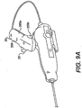
FIGS. 6A and6B are exemplary illustrations of a handle with a flexible shaft, in accordance with an embodiment. -
FIGS. 7A through 7C are exemplary illustrations of another handle with a flexible shaft, incorporating a grip, in accordance with an embodiment -
FIGS. 8A through 8D are exemplary illustrations of gears that permit a user to control degrees of freedom, in accordance with an embodiment. -
FIGS. 9A through 9C are exemplary illustrations of an ambidextrous handle being changed from right-handedness to left-handedness by detaching and flipping the handle, in accordance with an embodiment. -
FIGS. 9D and 9E are exemplary illustrations of an ambidextrous control handle with a split grip being changed from right-handedness to left-handedness by rotating the grip portions, in accordance with an embodiment. -
FIG. 9F is an exemplary illustration of an ambidextrous handle that can change handedness by rotating around an axis, in accordance with an embodiment. -
FIG. 9G is an exemplary illustration of an ambidextrous control handle that can be flipped in order to change handedness, in accordance with an embodiment. -
FIG. 9H is an exemplary illustration of another ambidextrous control handle that can be flipped in order to change handedness, in accordance with an embodiment. -
FIGS. 9I through 9K are exemplary illustrations of ambidextrous handles that can also be changed into a joystick configuration, in accordance with an embodiment. -
FIG. 9L is an exemplary illustration of a handle that can change between joystick configuration and side configuration, also including a rocker mechanism, in accordance with an embodiment. -
FIGS. 10A through 10C are exemplary illustrations of a catheter having a continuous body section with cut-outs that allow for articulation, in accordance with an embodiment. -
FIGS. 11A through 11C are exemplary illustrations of a catheter having multiple articulating ball sockets, in accordance with an embodiment. -
FIGS. 12A through 12G are exemplary illustrations of catheters having additional types of multiple articulating ball sockets, in accordance with an embodiment. -
FIGS. 13A through 13D are exemplary illustrations of catheters having articulation joints, in accordance with an embodiment. -
FIGS. 14A through 14E are exemplary illustrations of a tool including hydraulic control of the catheter, in accordance with an embodiment. - Described below are exemplary embodiments of tools that allow a user to perform a procedure, such as a surgical procedure, at a distance. In one aspect, a tool generally includes a proximal user interface (referred to herein as a control member or handle), an elongate catheter body, and a distal end. The proximal control member can control movement of the catheter and/or an end effector positioned proximate to the distal end of the tool. The tools described herein permit control of one, two, three, four, five, six, or more than six degrees of freedom via the handle and/or control member.
- In one embodiment, user input forces upon the handle can control movement of the handle relative to the control member and/or can control movement of the (entire) tool relative to a reference point (e.g., relative to a patient). For example, movement of the handle can control articulation of a catheter articulation section and/or actuation of an end effector. In one aspect, movement of the handle can drive one, two, three, or more than three degrees of freedom of the catheter and/or end effector. In another aspect, moving the control member (e.g., rotational and/or longitudinal movement relative to a point of reference) can control one, two, or more than two degrees of freedom.
- The tools described herein can be used with a variety of surgical or non-surgical system, including, for example, those described in United States Patent Application Nos.:
11/946,779 11/946,790 11/946,799 11/946,807 11/946,812 11/946,818 - While the discussion of devices, systems, and methods below may generally refer to "surgical tools," "surgery," or a "surgical site" for convenience, the described devices, systems, and their methods of use are not limited to tissue resection and/or repair procedures. In particular, the described systems can be used for inspection and diagnosis in addition, or as an alternative, to surgery.
-
FIG. 1 illustrates one exemplary embodiment of atool 10 comprising acontrol member 20,catheter 22, and endeffector 24.Control member 20 is illustrated in more detail inFIGS. 2A through 2G and can include ahandle 26 that allows a user to control actuation ofcatheter 22 and atrigger 28 that allows a user to actuate the end effector. - In one embodiment,
control member 20 includes abody 30 that houses a control mechanism for transferring user inputs onhandle 26 tocatheter 22 and/orend effector 24. User input forces can be directed into pull and/or push forces on one or more control wires that extend between the control mechanism and the catheter articulation section and/or end effector. As used herein, "control cable" refers to the various filaments, wires, cables, bowden cables (inner cable and/or outer sheath) which can transmit user inputs between the control mechanism and the distal portion of the catheter. Descriptions of exemplary cables, catheters, and end effector are disclosed below and in the above referenced United States Patent Applications. - Described below and illustrated in
FIGS. 2A through 2G are various exemplary control mechanisms. In one aspect, user inputs to the handle can rotate or pivot at least a portion of the control mechanism. Rotation around a first axis can control one degree of movement of the catheter and rotation around a second axis can control a second degree of freedom.Tool 10 can also, or alternatively, include a trigger mechanism for driving an additional degree of freedom. In one aspect, the trigger mechanism is position, at least partially, on or in the handle oftool 10. As used herein, the term "trigger mechanism" can refer to the variety of switches, buttons, rockers, and/or other such features for mechanically or hydraulically driving a degree of freedom, such as, for example, movement of the end effector. - As shown in
FIGS. 2A and2B , handle 26 can be rotatably coupled to the body ofcontrol member 20 such that the handle is able to move forward and aft. In one aspect, the handle rotatably couples withside rails shaft 320. Movement of the handle back and forth can cause the distal tip of thetool 10 to move in one plane while rotation ofhandle 26 about the longitudinal axis of theshaft 320 can cause movement of the distal tip of thetool 10 in another plane. - The handle can be secured to
side rails trunnion 316.Trunnion 316 includes a pair of outwardly extendingposts side rails posts - Forward/aft movement of the handle can pivot
trunnion 316, for example, around an axis extending throughposts cable receivers FIGS. 2C and2D , one of thecable receivers 358 is below the pivot point oftrunnion 316, and the other is above the pivot point. Upon tiltingtrunnion 316 in the control member, thecable receivers tool 10. -
FIGS. 2C and2D illustrate further detail oftrunnion 316. The control mechanism can include a stop to limit the amount of forward and aft movement of thehandle 26. In one aspect, aring 340 fits over the posts oftrunnion 316 and has anotch 342 therein. Apin 344 secured in the side rail (not shown) limits how far the handle can travel by engaging the ends of thenotch 342. Other structures besides pins can also be used. While the FIGS. illustrate a ring/pin configuration, one skilled in the art will appreciate that a variety of alternative mechanisms can be used to limit motion of the cable guide plate. In addition, the illustrated configuration could be reversed such that the notch could be located on the side rail and the pin could be located on the trunnion. -
Trunnion 316 can further includes an opening or slot in which a cable guide plate ordisk 328 is located. In the illustrated embodiment ofFIGS. 2B ,2C , and2D ,cable guide plate 328 is generally circular and mates with at least one control cable. In one aspect,guide plate 328 includes agroove 330 therein in which controlcable 332c is fitted. In addition,cable guide plate 328 can include anotch 334a that receives acorresponding cable stop 336 that is secured tocable 332c (while a single notch/stop/cable is illustrated, additional notches, stops, and/or cables are contemplated). Movement of the cable guide plate causes corresponding tension or relaxing ofcable 332c. - The
cable guide plate 328 can be fitted into a slot within the trunnion such that it lies behind thestop plate 326. In one aspect, theshaft 320 fits through a corresponding hole in thecable guide plate 328 and a snap ring or other fastening mechanism secures the components together. Rotation of thehandle 26 causes a corresponding rotation of theshaft 320 which in turn is coupled to thecable guide plate 328 to tension orrelease cable 332c. - Cable 332 is illustrated as wrapped around
disk 328 more than 360 degrees. In another aspect, cable 332 can be wrapped around the disk more than about 180 degrees, and in another aspect more than about 270 degrees. In yet another aspect, cable 332 mates todisk 328 without wrapping around a portion of the disc. In embodiments where the control mechanism includes a force limiter, the cable may also attach to the force limiter. - While a
single cable 332c is illustrated as mated withdisk 328, in another embodiment two control cables can mate with the disk. Rotation in a first direction can tension one of the two cables, while rotation in the other direction tensions the other of the two cables. - In one aspect,
trunnion 316 further includes astop plate 326 that provides an anchor for the ends ofcontrol cable sheaths Control cable 332a, mated withdisk 328, can extend throughbowden cable sheaths stop plate 326 pivots up and down with thetrunnion 316 as thehandle 26 is moved forward and aft. The bowden cables can permit the trunnion to pivot around posts 316a, 316b (controlling one degree of freedom) without (or with minimal) effect oncontrol cable 332a (which controls a different degree of freedom). - Also shown in
FIGS. 2C and2D is acontrol cable 346 that is actuated by thetrigger mechanism 28 on the handle. Depressingtrigger 28 causes a tensioning of thecable 346 to actuate, for example, anend effector 24 at the distal end of the tool. In the illustrated embodiment,cable 346 is a bowden-type cable having anouter sheath 348 with one end secured to acable stop 350 positioned on the shaft 320 (orcollar 324, or handle 26). The cable is not exposed outside the handle in one embodiment. The other end of the bowden cable housing extends through across bar 354 and joins a stop at the distal end of the catheter. Thecrossbar 354 also includes stops for thebowden cable housings -
FIGS. 2E and2F illustrate a trunnion with a dual pulley (or dual disk) system that serves as an alternate embodiment to the single-pulley system previously described. As used herein, the pulley or disk can comprise a rotating mechanism and is not limited to a circular member. As the tool handle is rotated in a first and second direction, the double-pulley configuration can apply a pulling force oncontrol wire control wires top pulley 335a corresponds tofirst cable 332a, and abottom pulley 335b corresponds tocable 332b. Each pulley contains only one control cable 332d and 332e. Typically, the twopulleys - A
top pin 337a drives thetop pulley 335a, while a bottom pin (not shown) drives thebottom pulley 335b. Unlike the single-pulley embodiment, the top and bottom pulleys each include arut 334b, such that therespective pin 337a can rotate freely in therut 334b without driving the respective pulley. Although referred to herein as pins, both thetop pin 337a and bottom pin (not pictured) can have other shapes, such as a protrusion with a flat surface for engaging the stop. -
FIG. 2E illustrates a double-pulley trunnion with the control stem 320 in a neutral position. In this position, a counterclockwise turn of thecontrol stem 320 will engage thetop pin 337a with the stop oftop pulley 335a. As a result,top pulley 335a pulls onfirst cable 332a, and the catheter bends. However, the bottom pin (not shown) swings in the rut of thebottom pulley 335b, and does not forcebottom pulley 335b to rotate. - Conversely,
FIG. 2F illustrates the double pulley interaction when thecontrol stem 320 rotates clockwise. Thetop pin 337a rotates inrut 334b, and consequently does not push or pullfirst cable 332a. On the other hand, the bottom pin engages the stop of thebottom pulley 335b, and thebottom pulley 335b rotates clockwise. This rotation applies tension to the right wire, which is pulled towards thebottom pulley 335b. - As a result, neither
wire 332a gets forcefully pushed out by the top orbottom pulleys - Further detail of one embodiment of a
trigger mechanism 28 is shown inFIG. 2G . In the illustrated embodiment, thetrigger 28 is rotatably received within thehandle 26 such that squeezing thetrigger 28 causes it to rotate about a pivot point. Thetrigger 28 includes anarm 360 to which an end of theactuation cable 346 is secured. As thearm 360 is moved by pressing the trigger, tension on thecontrol cable 346 is increased to actuate the end effector. A roller orpulley 362 changes the direction of thecontrol cable 346 from within the handle to a direction that extends along theshaft 320. -
FIGS. 2H and 2I illustrate another embodiment of a trigger mechanism that includes abutton 366 for activating the distal end oftool 10. Abowden cable 368 can extend intohandle 26 to triggermechanism 370. The second end of the outer sheath 372 of the bowden cable extends in clearance throughcrossbar 354 and through the body of surgical tool where it terminates proximate to end effector. The outer sheath 372 of thebowden cable 368 can mate with astop 374 in the trigger mechanism while the inner filament 376 extends intotrigger mechanism 370. Whenbutton 366 is depressed,trigger mechanism 370 tensions inner filament 376. In one aspect,trigger mechanism 370 include a ratchet-type lock that prevents the release of inner filament 376 once tensioned. A button 378 can be depressed to release inner filament 376 and allow the distal end oftool 10 to return to its original configuration. -
FIGS. 2J and2K illustrate one embodiment of a coupling mechanism that can be used to selectively couple thecontrol member 20 to one or more control wires (i.e., control cables) within the tool 10 (e.g., within catheter 22). Thecoupler 380 forms an end-wall that is positioned within the actuator housing between the support rails 310a, 310b. Thecoupler 380 has a number of spring loadedpins pins handle 26 or the trigger mechanisms as described above. Each pin includes acable receiving notch 384 therein that receives the ball or stop at the end of acorresponding control cable slots 384, each pin allows the tensioning or release of the correspondingcables pins control member 20. Thesprings 388 serve to tension the control cables within the body of the control when not being pulled by the actuator and biases the control handle to return to a home position. - To connect the cables of
catheter 22 oftool 10 to thecontrol member 20, the terminal ends of each of thecontrol cables cable receiving slots 384 of the corresponding pins. Similarly, to disconnect the cable, the balls or cable ends are removed from thecable receiving slots 384. Upon completion of a procedure, the catheter can be uncoupled from thecontrol member 20, cleaned or sterilized for re-use or thrown away. - In one aspect, the various cables within
control member 20 can be adjustably tensioned. For example, in one embodiment spring loaded pins 382 can have a threaded connection with coupler 380 (additional disconnect configurations are described below). Rotating pins 382 can move pins laterally to control the tension on control wires mated to pins 382. For example, rotating the pins 382 can compress or relaxsprings 388 and adjust tension on the control wires. - In another embodiment,
tool 10 does not include thecoupler 380 or the spring and pin arrangement shown inFIG. 2J . In such an embodiment, thedisc 328 mates with one end of the control wire(s) while a catheter articulation section and/or end effector mates with the other end of the control wire(s). Removing the springs can increase the tactile feedback and efficiency of thetool 10, because the user need not overcome the bias of the springs when controlling thetool 10. - Because the springs also return the catheter articulation to a home position (such as straight), a spring-less embodiment may not have this feature. However, for some procedures, it is preferable for the catheter and/or end effector to remain in a current position without automatically returning to a home position. The ability to leave the
tool 10 in a current position can free the user to perform another task instead of maintaining constant control overtool 10. - In accordance with this need, either type of tool 10 (springs or no springs) can include a mechanism for locking the catheter and/or end effector into place. One such mechanism includes a pawl that interlocks with teeth to stop actuation. In one aspect, the user can lock and unlock the actuation by manipulating a button, slide, or trigger mechanism that engages and disengages the pawl with the teeth.
- The location of the pawl and teeth can vary, depending on the type of actuation it controls. For example, a
handle 26 can be locked by providing a locking mechanism for the stem. A locking mechanism on the trigger, push-pull mechanism, etc. can lock the end effector in place. This can allow the user to position and lock a clamp in place for the duration of some other step of the procedure. - In another embodiment of
control mechanism 20,tool 10 can include a orientation adjuster. In use, the orientation adjuster can allow a user to rotate the elongate body and distal end of a tool relative to controlmechanism 20.FIG. 3 illustrates a cross-section of the distal end ofcontrol mechanism 20 withadjuster 394.Adjuster 394, in one aspect, can include aninner member 392 having apassageway 390. Thepassageway 390 can mate with the elongate body (not illustrated) ofcatheter 22. In one embodiment, the elongate body ofcatheter 22 includes an outer sheath that fixedly mates to the inner surface ofpassageway 390. One skilled in the art will appreciate that a variety of mating mechanisms, such as, for example an adhesive, mechanical interlock, and/or frictional engagement can be used. In addition, theinner member 392 can mate with the inner surface ofadjuster 394. For example, as illustrated inFIG. 3 ,adjuster 394 includes anaperture 396 for a set screw for mating adjuster andinner member 392. In another aspect, adjuster and 394 andinner member 392 can be fixedly mate via, for example, an adhesive. In addition, the adjuster and the inner member can be formed as a single body. - To change the rotational orientation of
catheter 22,adjuster 394 can be rotated withincontrol member 20. In one aspect, alocking collar 395 can be tensioned to control the amount of friction between the control member andorientation adjuster 394. For example, thelocking collar 395 can be set to inhibit, but not prevent rotation of the adjuster, or set to prevent rotation until adjustment is desired. Sinceadjuster 394 is mated toinner member 392, andinner member 392 is mated to the body ofcatheter 22, rotatingadjuster 394 causescatheter 22 to rotate relative to controlmember 20. - Described below are alternative control mechanisms for actuating
catheter 22 and/orend effector 24.FIG. 4 illustrates handle 261 having a "joystick" configuration. In general, a handle in joystick configuration stands on its end rather than on its side. In one aspect, the control member can include a trunnion-type configuration as describe above, that provides at least one degree of freedom to handle 261. However, instead of the handle positioned orthogonally toshaft 320 as described above, handle 261 can be parallel to the axis ofshaft 320. For example, handle 261 can be co-linear withshaft 320. - Forward-aft movement of
handle 261 can be achieved in a similar fashion to the trunnion and disk configuration discussed above. For example,control member 20 ofFIG. 4 can includetrunnion 316 that rotatably mates withside rails disk 328. Base 317 can mate with cables (not illustrated) to control one degree of freedom ashandle 261 is moved forward-aft. -
Disk 328 can reside in base 317 and movably mate therewith. Twisting orrotating handle 261 can rotatedisk 328 to control another degree of freedom. For example,rotating handle 261 about its axis can direct side-to-side movement of the catheter. - Handle 261 can also include a
trigger 28 that controls, for example, a third degree of freedom.Actuating trigger 28, in one aspect, can controldistal end effector 24. The trigger mechanism withinhandle 261 can have a configuration similar to the triggers discussed above. Thus, the control mechanism ofFIG. 4 can work in a similar fashion to the control members ofFIGS. 2A through 3 , but withhandle 261 in a different orientation compared withhandle 26. -
FIG. 5 illustrates an alternative handle orientation. Rotatinghandle 262 around its axis (axis A-A) can control one degree of freedom. For example, rotating the top surface ofhandle 262 away from the user can move the distal tip of the catheter down and rotating the top surface ofhandle 262 toward the user can move the distal tip of the catheter up. Handle 262 can also be rotated around an axis, such as, for example, an axis orthogonal to the longitudinal axis of the tool, to control another degree of freedom. In one aspect, handle 262 can be rotated around axis B-B to control side-to-side movement of the distal end of the catheter. - In one aspect, actuation is achieved via a control mechanism similar to those described above.
FIG. 5 illustrates a trunnion and disk configuration similar to that ofhandles trunnion 316, while rotation ofhandle 262 around its axis can movedisk 328. However, unlike the mechanisms described above, handle 262 can drivedisk 328 via a belt and/or chain drive. Apulley 50a connected to handle 262 can drivepulley 50b viabelt 52.Pulley 50b can mate with ashaft 54 that extends todisk 328. - Rotation around axis B-B can be driven through a frame or shaft (not illustrated) extending between
handle 262 andtrunnion 316 to transfer rotational force between the handle and trunnion. Rotational forces can additionally, or alternatively, be applied onshaft 54 through the belt and pulley system. - In another embodiment, rotating the
handle 262 around axis A-A actuates an end effector. This is just one of various actuation members discussed herein. -
FIGS. 6A and6B illustrate handle 263 defined at least in part by aflexible shaft 60 that is articulated to controlcatheter 22. In one aspect, bendingshaft 60 up-down or left-right can control a degree of freedom. The distal end 62 ofshaft 60 can mate withcables 61. Where two degrees of freedom are controlled via movement ofshaft 60, four cables can mate withshaft 60 and extend along a path proximate to the outer surface of the shaft. Bending of the shaft can pullcables 61 by increasing the length of one side of the shaft. As the length ofshaft 60 increases with bending, the cable adjacent to the lengthened side is pulled. While four cables and two degrees of freedom are illustrated inFIG. 6A , fewer cables and/or degrees of freedom could be provided. - In one aspect,
shaft 60 allows a user to control two degrees of freedom at once. Bending the shaft outside of the forward-aft or side-to-side plane (e.g., at a 45o angle to the forward-aft movement) can pull on two control cables that control separate degrees of freedom. Thus, a single motion can ofshaft 60 can control two degrees of freedom simultaneously. -
Shaft 60 is formed, in one aspect, is formed from aspring 65. As the shaft is bent, the coils along inside surface of the curve converge while on the opposite side of the shaft the coils move away from one another.Spring 65 can also provide a neutral bias such that when the shaft is released, the catheter returns to a "home" or linear configuration. One skilled in the art will appreciate that the force required to bend the spring and the amount of bend can be chosen by varying the spring materials, the spring wind, pre-compression, and/or the spacing between coils. -
Shaft 60 could additionally or alternatively be formed from an elastomic material, such as flexible, compressible, resilient, and/or elastic materials that allow bending. In one aspect,shaft 60 is formed from a flexible polymer or elastomer, such as, for example, silicon. In another aspect,shaft 60 is formed from a series of wafers. Bending is achieved by expanding the distance between wafers along one side of the shaft and/or decreasing the distance between wafers on the opposite side of the shaft. -
Shaft 60 can further comprise anouter sheath 63 that covers spring 65 (or other material forming shaft 60) to provide a barrier betweenspring 65 and a user's hand. In one aspect,sheath 63 can be formed of stretchable or loose material to permit actuation of the shaft. In addition, or alternatively,sheath 63 can be formed of a lubricious material and/or include a lubricious coating to allowsheath 63 to slide over the outer surface ofspring 65 asshaft 60 is bent. - The
control member 20 can also includepulleys 64 which change the direction of the cables and the force applied through the cables. In one aspect, each cable corresponds to at least onepulley 64. - Handle 263 can, in one aspect, include a trigger, button, or finger loop to permit an additional degree of freedom. As illustrated in
FIG. 6 , handle 263 can include afinger loop 66 that is actuated by movement along the axis of the shaft. Pushingloop 66 away from the shaft can actuate, for example,distal end effector 24. Alternatively, or additionally, a user can moveloop 66 towardshaft 60 to actuate the end effector. - To increase user comfort,
control member 20 can include anarm rest 68. A user can place his or her forearm inarm rest 68 while grabbing and actuatingshaft 60. Thearm rest 68 can also deliver and/or isolate certain degrees of freedom of the control handle. For example, the tip movement can be isolated versus the entire control movement in one embodiment. -
FIGS. 7A through 7C illustrate another exemplary embodiment of ahandle 264 incorporating aflexible shaft 60 extending between aproximal end 100 and adistal end 102. However, instead of directly graspingflexible shaft 60, handle 264 can include agrip 104 for a user interface.Grip 104 can have a variety of configurations. In one embodiment,grip 104 includes an aperture for receiving a portion of a user's hand. In addition, the inner surface ofgrip 104 can include atrigger 106 for actuating an additional degree of freedom. - In one aspect, the distal end of
flexible shaft 60 remains stationary while the proximal end ofshaft 60 is bent. In particular,shaft 60 can extend in a distal to proximal direction fromcontrol member 20 and/orcatheter 22 such that pulleys are not needed to change the direction of the control wires. In use, bendingshaft 60 in one direction can move the distal tip of the catheter in the opposite direction. For example, bending the shaft up can move the distal tip down and visa versa. However, control wires can be redirected or crossed if it is desired to change the correspondence betweenhandle 264 and the distal tip of the catheter. - In another embodiment, instead of a flexible shaft, handle 265 can drive gears to control at least one degree of freedom.
FIGS. 8A through 8D illustrate gears that permit a user to control two degrees of freedom. Handle 265 can include arigid shaft 70 extending between a proximal anddistal end proximal housing 75 proximate toproximal end 71. The proximal housing can include a first set of teeth 72 (FIG. 8B ) positioned on the proximal surface thereof. Forward-aftmovement cause teeth 72 to drive agear 74 as the first set ofteeth 72 mesh with a second set ofteeth 76 ongear 74. Acontrol wire 61a mated withgear 74 is then driven asgear 74 rotates to control one degree of freedom. - To permit an addition degree of freedom,
shaft 70 can be moved side-to-side.FIG. 7B illustrateproximal housing 75 mating with and driving a control wire. Side-to-side movement ofshaft 70 pivotshousing 75 which in turn drives asecond control wire 61 b mated with the housing. As the shaft moves side-to-side, the first and second set ofteeth shaft 70 has a semi-spherical shape such that as the shaft moves side-to-side, the first teeth do not loose contact with the second set of teeth. - In another aspect, instead of proximal housing mating with
control wire 61 b, ashaft 80 can include a surface for mating with and drivingcontrol wire 61 b.Proximal housing 75 can be anchored or supported via ashaft 80 that extends through the proximal housing and throughslots shaft 80 becauseslots shaft 80 to remain in place ashousing 75 moves relative toshaft 80. Thus, forward-aft movement ofhousing 75 is independent from shaft 80 (for at least some distance). However, side-to-side movement ofshaft 70 causesproximal housing 75 to rotateshaft 80 around an axis S-S (FIG. 8C ) and drivecontrol wire 61 b mated withshaft 80. In particular, with respect toFIG. 8B , the surface on whichcontrol wire 61 b rests can be defined by a portion ofproximal housing 75 or by a bulbous portion ofshaft 80. - Alternatively, or additionally, a third and fourth set of teeth within
housing 75 can transmit side-to-side motion into push-pull motion on a control wire (e.g.,control wire 61 b). For example, as illustrated in FIG. 7D,proximal housing 75 can includes a third set ofteeth 82 that mesh with a fourth set ofteeth 84 on asecond gear 85. As theproximal housing 75 moves side-to-side,teeth 82 on the inner surface ofhousing 75drive teeth 84 ongear 85 causinggear 85 to rotate and drivecontrol wire 61 b (not illustrated). During forward-aft movement, the third and fourth sets ofteeth - These and other handle embodiments can be oriented ergonomically for greater comfort and usability. For example, returning to
FIG. 1 , handle 26 is tilted off axis from parallel alignment withbody 30 ofcontrol member 20. In combination with the location oftrigger 28, the orientation ofhandle 26 provides for easy right-handed use of thecontrol member 20. - An embodiment can include two
control members 20 mounted on a frame and oriented for left and right handedness, respectively, for simultaneous use. For example, a user may wish to control afirst tool 10 with the right hand while controlling asecond tool 10 with the left hand. Orienting one handle for lefthand use and the other handle for right-hand use gives the user greater flexibility and comfort when using the tools. - Various tools described herein can provide ambidextrous use by permitting changing handedness. In one aspect, the tool handle can be changed between left-handed and right-handed. In another aspect, the user can switch the orientation of a tool on-the-fly. By doing so, the user can operate multiple combinations of tools with either hand during a single procedure.
FIGS. 9A through 9K illustrate a few exemplary implementations of this feature. However, the teachings ofFIGS. 9A-9K can also apply to other handle embodiments described herein. - A first type of ambidextrous handle detaches from the control mechanism to permit a change in handedness. For example, the handle can be detached and flip upside down to change handedness.
FIGS. 9A through 9C illustrate this concept with a tool similar to the one described with reference toFIG. 1 .FIG. 9A presents the handle in a right-handed configuration. Thehandle 269 includes afirst side 269a facing up and asecond side 269b facing down. Each of the first andsecond sides control stem 320. In this configuration, the trigger is positioned activation by a user's right hand index finger. -
FIG. 9B illustrates handle 268 detached fromstem 320 and flipped over into a left-handed orientation. Thefirst side 269a now faces downward, while thesecond side 269b faces upward. Themating feature 339 on thefirst side 269a also faces downward, allowing the handle to mate withstem 320. -
FIG. 9C illustrates handle 268 in the final mounted left-handed configuration. In this configuration, trigger 28 is positioned for activation by the index finger of the user's left hand. - The mating features 339 for engaging and disengaging the handle can comprise, for example, a variety of mechanical and frictional mating features. In one embodiment, the mating feature is an opening in for receiving a portion of
stem 320. In another aspect, the opening extends from the top of thehandle 267 to the bottom. The mating feature can also comprise a protrusion that mates with an opening in the shaft or control body. In still another embodiment, the two mating features 339 are located on the same side of thehandle 267 grip, but allow for attaching with thestem 320 in order to suit different handedness. - A second type of ambidextrous handle is illustrated in
FIGS. 9D and 9E . Unlike the previous type, thehandle 266 can change the orientation oftrigger 281 viarotating handle portion 266a. In addition, handle 266 can change orientation with respect tohouse 30 ofcontrol member 20 via rotation of handle 226 between a right-handed configuration and a left handed configuration. - In one aspect, handle 266 includes first and
second handle portions pivot 338.rotating handle portion 266a with respect to 266b, changes the orientation oftrigger 281. In addition,first handle portion 266b can rotatably connect to the stem or control body of the tool. Rotatinghandle portions handle 266. - As illustrated in
FIG. 9D , therotatable portion 266a can include a push-pull mechanism 281 oriented for right-handed use. The push-pull mechanism 281 is a trigger that operates much like a scissor, and allows the user to control an end effector and/or actuate a catheter. For example, the push-pull mechanism 281 can push or pull a cable that runs through a hole inpivot 338, and down thestem 320 into the body of the control device. - By rotating both handle
portions pull mechanism 281 to a different handedness.FIG. 9D includes a stem axis (axis S-S) and handle axis (axis H-H) for further clarity. Thefirst portion 266b andsecond portion 266a rotate around the stem axis, while thesecond portion 266a also rotates around the handle axis. As a result, thefirst portion 266b and thesecond portion 266a switch sides, as shown inFIG. 9E . The orientation of thetrigger 281 also reverses because it is attached to thefirst portion 266a. - To allow for rotating the sections to change handedness, the
handle 266 includes twoswitches rotatable portion 266a from swiveling at thepivot 338 with anglingportion 266b engaging and disengaging a first mating structure (not pictured). Switch 292 locks and unlocks the anglingportion 266b of thehandle 266 from thestem 320 by engaging and disengaging a second mating structure (not pictured). Potential mating structures include a tooth, pin, clamp, detent system, strap, or any other known structure for mechanically locking and inhibiting movement between two members. - In another embodiment, both
portions - The user can adjust the
handle 266 to a more comfortable orientation in one embodiment by rotating theappropriate portion 266a and/or 266b. For example, the user can rotate the push-pull mechanism 281 upwards and/or manipulating the horizontal orientation of the handle grip. When the user positions thehandle 266 as desired, theportions - A third type of ambidextrous handle, shown in
FIG. 9F , can change handedness by rotating in only one plane.FIG. 9F illustrates ahandle 269 that is round and contains aswitch 284 in the form of a button. As illustrated, thehandle 269 has a left-handed configuration, wherein the user controls switch 284 with their left thumb. - To change the handedness, handle 269 rotates relative to the
control body 30 orstem 320.Switch 292 unlocks thehandle 269 for rotation. In one embodiment, unlocking does not detach thehandle 269 from thestem 320 or controlbody 30, but instead allows thehandle 269 to rotate around thestem 320. In another embodiment, thehandle 269 remains locked to thestem 320, but thehandle 269 and stem 320 rotate together, relative to thecontrol body 30. Similarly, in embodiments where nostem 320 exists, rotation may occur around some other axis, such as axis S-S. Even in embodiments that include astem 320, such asFIG. 9F , rotation need not necessarily occur around an axis through the stem. For example, thehandle 269 inFIG. 9F could alternatively rotate around axis S-S. - In an embodiment that accomplishes ambidexterity through this rotational approach, a
single opening 339 can suffice for mating with the control stem. -
FIGS. 9G through 9L illustrate some alternate handle embodiments that implement the rotational and detachable characteristics of handles already described. Some of these embodiments implement additional characteristics, such as a joystick configuration option. -
FIG. 9G illustrates anambidextrous handle 267 with a push-pull mechanism 281 (another type of trigger). The push-pull mechanism 281 pushes and pulls the inner-filament ofcable 346, which transfers forces from thehandle 267 to the end effector. As shown inFIG. 9G , the cable can exit thehandle 267 from afirst exit point 347a in one embodiment, or asecond exit point 347b in another embodiment. An exterior cable allows the user to detach and flip thehandle 267 even thoughhandle 267 includes a trigger. In one embodiment, thetrigger 281 can still be used whenhandle 267 is detached. - In one embodiment, the
cable 346 passes though a firewall (such as described with reference toFIGS. 2H and 2I ). Conversely, in another embodiment, thecable 346 passes directly from the handle to the articulation section of the catheter, without the use of the firewall. -
FIG. 9G also illustrates an exemplaryalternative cautery connection 348 for use in cauterization procedures. Of course, other embodiments do not implement this feature but still use thehandle 267 shown inFIG. 9B . -
FIG. 9H illustrates ahandle 268 that can change handedness by either detaching and flipping or by simply rotating relative to the stem. Because thetrigger 282 and handle 268 can conform to either hand without being flipped vertically, rotating the handle with respect the stem reorients the handle. Similarly, flipping the handle vertically also switches the handedness. - The
handles 268 illustrated inFIGS. 9I through 9L provide even further flexibility by providing anadditional opening 349 to allow the user to stand the handle on end in joystick configuration. The user may, therefore, select to operate thehandle 268 with the grip laying flat by connecting the handle at opening 339, or as a joystick by connecting to the stem atopening 349. As previously described,switch 292 locks and unlocks thehandle 268 from the control stem. -
FIG. 9k illustrates ahandle 268 that includes a mating feature 349' at the bottom of a rounded boss. This mating feature puts thehandle 268 in pistol grip configuration, which is another type of joystick configuration. Handle 268 also includes analternate mating feature 349 for yet another joystick configuration. -
FIG. 9L illustrates anambidextrous handle 268 that can be flipped for orientation with either hand, and, alternatively, stood on its end in a joystick configuration. - The illustrated
handle 268 includes arocker mechanism 283, which is yet another type of trigger. Therocker mechanism 282 allows a user to articulate the end effector and/or articulation section of a catheter by performing a rocking motion. Rather than swinging outward like a scissor, therocker mechanism 282 incorporates a see-saw action, such that pushing one side down forces the other side up. Therocker mechanism 282 can be spring-loaded for returning to a home position. Conversely, in another embodiment, the rocker remains in its last position until adjusted by the user. - Further described herein are alternative configurations of the catheter. In one aspect,
catheter 221 includesbody 90 configured to provide increased torsional strength. As shown inFIGS. 10A through 10C ,catheter 221 can include a continuous body section having cut-outs 92 to permit (or ease) flexing and/or bending. The catheter includes a series of opposing cut-outsections FIG. 10B ) with each pair of opposing cut-outs adjacent another pair of opposing cut-outs 92c, 92d (FIG. 10B , 92d not illustrated) positioned at an angle with respect thereto. In one aspect, adjacent cut-out pairs are offset by about 90 degrees. In particular, side cut-outpairs 92c, 92d are positioned adjacent to top-bottom cut-outpairs - In another embodiment,
catheter 222 can transmit torsional loads via mechanical interlocks between adjacent catheter body segments.FIGS. 11A through 11C illustratesegments 120 having articulatingmechanical interlocks 122. The interlocks allow pivoting but do not allow rotation and/or translation of the segments with respect to one another. In other words, the mechanical interlocks limit at least one degree of freedom between adjacentcatheter body segments 120. - In one aspect,
mechanical interlocks 122 include a male-female connection that permits only one degree of freedom. For example,male mating member 124 can have an elongate, curved outer surface that is received in an elongatefemale mating member 126 having a corresponding shape. While interlocked, the male mating member can pivot within the female mating member along an axis parallel to the elongate male and female mating members. However, the male-female interlock can inhibit pivotal movement on other axes. In addition, the male-female interlock can inhibit relative rotational, longitudinal, and/or transverse movement between the adjacent segments. - For example, with respect to
segments FIG. 11A ) the mechanical interlocks permit up-down pivoting, but not side-to-side pivoting. Conversely,adjacent segment 120c can pivot side-to-side with respect tosegment 120a, but the mechanical interlock betweensegments catheter 222 permit up-down and side-to-side articulation, but inhibit at least rotational movement between the segments. In this way, the segments maintain torsional integrity throughout the length ofcatheter 222. -
FIG. 11B shows a close-up side view of a ball socket (e.g., mechanical interlock). The socket ofsegment 120a holds the curved member ofsegment 120b in place by extending past the center point 124' of the curved member. In this way, the socket wraps more than half way around the curved member. As a result, the width of thesocket opening 125b is less than the greatest diameter of thecurved member 125a. - In addition, the curved member can be held in place laterally by the incorporation of one or more stops. For example, a the socket can have an inner wall that contacts the side of the curved member. In one embodiment, the contacted inner side of the curved member is flat. Providing an inner wall on the matching socket at the other side of the same segment can prevent the connected segment from sliding loose laterally. Alternatively or in addition, a stop can exist on the outer side of the curved member. The outer stop can also integrate with the socket in one embodiment.
- An over sheath can also prevent slippage or separation of the
segments 102a and 120b. The over sheath may be an elongate bendable layer that surrounds the exterior of the segments. In addition to holding properties, the over sheath can prevent pinching when the catheter articulates. - In one embodiment, the segments include one or
more holes 128 for receiving a cable. Theholes 128 of each segment align such that the cable can be threaded though multiple sections over an articulation section. When the cable is pulled from the proximal end of the catheter, such as by the control mechanism, the segment(s) bend within the articulation section. In one embodiment, the articulation section can bend in multiple directions (e.g., left/right, up/down). - In another embodiment, the articulation section is comprised of at least one bendable and torque stable segment. While the segment(s) can be articulated from side to side and front to back, they remain rotationally rigid so that the end effector better withstands torsional forces.
-
FIGS. 12A through 12E illustrate another embodiment of acatheter 223 utilizing mechanical interlocks for at least one degree of freedom. InFIG. 12A , the catheter includes an articulation section 155 and arigid section 154. When a user manipulates the handle oftool 10, and articulates thecatheter 223, articulation occurs along the articulation section 155. The articulation section includes multiple joint segments mechanically interlocked via entrappingballs 153.Cables 133 or other structures apply the tension to flex the articulation joints. An over braid or other sheath covers the articulation joints to prevent pinching when the articulation joints flex. -
FIG. 12B shows this arrangement in detail. The articulation section 155 begins with a firstjoint segment 152a interlocked with a second joint segment 152b. The entrappingball 153 fits within a socket pivot point in second joint segment 152b. By repeating this arrangement down the length of thearticulation section 223, a chain of joint segments allow torque transfer from one segment to another. As a result, the articulation section achieves at least one degree of freedom. - In one embodiment, such as shown in
FIG. 12C , the joint segments have a recess or opening defining a passageway. Through this passageway, one or more push-pull cables, electrical cables, lumens, and/or other tubing can access the end effector. In another embodiment, the joint segments are divided into quadrants. - While the articulation joints of
FIG. 12E allow only side-to-side movement of thearticulation section 223,FIG. 12D depicts multiple joint segments interlocked via entrappingballs FIG. 12D alternate in type. For example,segment 157a includes two entrappingballs next segment 157b contains no entrapping balls but has two mating sockets, one on each side, for connecting with the entrapping balls in two different planes. - The catheter can be driven by user inputs. These inputs drive the articulation section in one embodiment. In another embodiment, portions of the catheter other than the articulation section can also be driven. Articulation does not require bending separate parts. Instead, it more broadly refers to the bending of the body as a whole.
- The articulation section of
FIGS. 12A though 12E can be constructed by micro-welding the segments together. Entrapping the ball and socket reduces the chances of segments slipping loose from one another, and also provides a low cost articulation section because other parts are not necessarily required. Preferably, each socket entraps the ball for more than 180 degrees, as shown inFIGS. 12A through 12E . -
FIGS. 12F and 12G illustrate another type of ball socket system.Curved member 153 snaps into a socket. Thus, the catheter can be constructed from snapping together the segments. In addition, the segment body provides inner stops to keep the segments from sliding laterally. -
FIGS. 13A through 13D illustrate yet another type of articulation joint for use in a catheter.FIG. 13A shows the cross section of a continuous structure 225 (or series of structures), which forms a cross shape, dividing the inside of the catheter into fourquadrants Eyelets 166 along the periphery of the structures receive control cables for articulating the catheter. - The articulation segments of
FIGS. 13A to 13D are fixedly mated with one another and/or formed of a single, continuous structure 225 (or series of structures) that bends athinges - The degrees of freedom are controlled based on the position of the hinges within
body 164. In one aspect, each hinge only allow for bending in one plane with adjacent hinges offset from one another. For example, afirst hinge 167a can permit up/down movement, while asecond hinge 167b can permit left/right movement. The shape segments and/or the hinges can control maximum bending limits for the catheter. For example, to restrict bending, thespace 169 between adjacent segments can be narrowed. - A multidirectional hinge is also possible if the
continuous structure 225 is thin in both planes atpoint 168. -
FIGS. 14A through 14E illustrate another embodiment oftool 10 including hydraulic control of at least one degree of freedom. In one aspect,catheter 223 includes at least one fluid pathway that can receive a hydraulic fluid (e.g., generally any fluid and not necessarily "industrial" hydraulic fluids) to control one degree of freedom. In another aspect, two fluid pathways can be formed incatheter 223. As shown inFIG. 14A ,device 10 can include twofluid actuators fluid pathways fluid actuators catheter 223 to bend. - For example, when a
piston head 131a offluid actuator 130a is pressed inward and moves distally withinfluid actuator 130a, thepiston head 131 a forces fluid out of thefluid actuator 130a and intofluid pathway 132a. While the amount of fluid in thefluid actuator 130a on the distal side of thepiston head 131 a decreases, the amount of fluid in thefluid pathway 132a increases. Simultaneously, thispiston head 131a movement draws fluid out offluid pathway 132b, and intofluid actuator 131a on the proximal side ofpiston head 131a. -
FIG. 14B illustrates a cross-sectional view of one exemplary aspect ofcatheter 223. Eachfluid pathway catheter 223 and a bending toward the reduced-volume fluid pathway. - Alternatively, as illustrated in
FIGS. 14C through 14E ,catheter 223 can have a configuration similar to the catheter illustratedFIGS. 9A through 9D . The cut-outs 92 incatheter 223 can define a portion offluid pathways outs FIG. 14C , anouter sheath 136 can enclose thebody 138 ofcatheter 223 and cut-outs 92. When the cut-outs increase in size or volume,outer sheath 136 can stretch allowcatheter 223 to bend. - In another embodiment, the shapes of inflated
fluid pathways catheter 223. As fluid fills a particular pathway, the pressure forces the articulation section ofcatheter 223 to conform to the shape of that fluid pathway. A user can use this embodiment to lock thecatheter 223 into a particular curved shape, for example. - While
catheter 222 is illustrated as having expandable fluid pathways (or cut-outs) along its whole length, in another aspect, only a portion of the catheter is articulating (i.e., the articulation section). For example, a distal portion of thecatheter 223 can include cut-outs or fluidly expandable chambers or pathways to permit articulation. - One skilled in the art will appreciate that the degree of articulation (i.e., the amount of bend) can be varied depending on the amount of hydraulic pressure applied and/or on the material of
catheter 223, the size of the fluid pathway, the shape of the fluid pathway, and/or the location of the fluid pathway. - Regardless of the configuration of the fluid pathways,
catheter 223, like the catheters described above, can include at least one channel for the passage of at least one medical tool. For example, as illustrated inFIGS. 14B and 14C ,channel 134 is positioned along the central longitudinal axis of the catheter and is surrounded byfluid pathways Channel 134 can serve as a lumen or multiple lumens in other embodiments. - Other embodiments will be apparent to those skilled in the art from consideration of the specification and practice of the embodiments disclosed herein. It is intended that the specification and examples be considered as exemplary only, with a true scope and spirit of the embodiments being indicated by the following claims.
- A variety of alternative control members, which allow a distal end of tool 40 to be actuated in the up/down, right/left, forward/backward, and rotational directions, can be used with
system 20. Such alternative control mechanisms are disclosed, for example, inU.S. Patent Application No. 11/165,593 , entitled "Medical Device Control System" andU.S. Patent Application No. 11/474,114 , entitled "Medical Device Control System," both of which are hereby incorporated by reference in their entirety. -
- 1. A drive system, comprising:
- a control handle including a flexible body extending between a first and second end, wherein at least two control wires extend along at least a portion of the flexible body proximate to opposing side surfaces of the flexible body, wherein bending the flexible body increases the length of one of the opposing side surfaces and causes a force to be applied to at least one of the control wires; and
- a flexible shaft having an articulation section, wherein applying a force on at least one of the wires drives the articulation section.
- 2. The system of
clause 1, wherein the flexible body includes an elastomic material. - 3. The system of clause 2, wherein the control wires lays against an outer side surface of the elastomic material.
- 4. The system of clause 2, wherein the control wires are embedded within the elastomic material.
- 5. The system of
clause 1, wherein the body includes a spring. - 6. The system of
clause 5, wherein the control wires lay against an outer side surface of the spring. - 7. The system of
clause 1, wherein the at least two control wires extend between the handle and the flexible shaft. - 8. A drive system, comprising:
- a control handle;
- a pivoting member having a first set of teeth positioned on a curved surface; and
- a second set of teeth positioned on a gear, wherein the gear is mated with a control wire for driving an articulating catheter,
- wherein moving the control handle in a first plane drives the gear, and wherein moving the control handle in a second plane causes the first set of teeth to move relative to the second set of teeth without driving the gear.
- 9. The system of clause 8, further comprising a shaft mated with a second control wire.
- 10. The system of clause 9, wherein the member drives the shaft when moved in the second plane and does not drive the shaft when moved in the first plane.
- 11. The system of clause 8, wherein the member comprises a third set of teeth.
- 12. The system of clause 11, wherein a fourth set of teeth is meshed with the third set of teeth, the fourth set of teeth positioned on a gear mated with a second control wire.
- 13. The system of clause 8, further comprising a locking mechanism that allows for locking at least one set of teeth to eliminate a degree of freedom.
- 14. A method for controlling a catheter, comprising:
- providing a control mechanism for articulating a catheter comprising;
- a handle,
- a first member having a curved surface with first teeth positioned thereon,
- a second member with second teeth meshed with the first set of teeth, a first control wire for controlling a first degree of freedom, and
- a second control wire for controlling a second degree of freedom;
- moving the handle in a first direction and driving the second member and second control wire; and
- moving the handle is a second, different direction and driving the first member and first control wire without driving the second member,
- wherein moving the handle in the first direction controls a first degree of freedom of a catheter articulation section and wherein moving the handle in the second direction controls a second degree of freedom of the catheter articulation section.
- providing a control mechanism for articulating a catheter comprising;
- 15. The method of clause 14, wherein moving the handle upward articulates the catheter upward.
- 16. The method of clause 14, wherein moving the handle in the first direction controls the first degree of freedom without driving the second degree of freedom.
- 17. A drive system, comprising:
- a control handle that has at least three degrees of freedom;
- a control mechanism coupled to the control handle;
- a catheter including an articulation section; and
- a cable including a proximal end and a distal end, wherein the proximal end is coupled to the control mechanism and the distal end is coupled to the articulation section,
- wherein the cable articulates the articulation section by transferring force applied by the control handle.
- 18. The drive system of clause 17, wherein the control mechanism rotates around a first axis to transfer the force applied by the control handle.
- 19. A drive system, comprising:
- a first tool adapted for use by a left hand; and
- a second tool adapted for use by a right hand, the second tool comprising:
- a control handle;
- a housing containing a pivoting control mechanism being driven by the control handle;
- a catheter having an articulation section; and
- a first control wire including a proximal end and a distal end, the proximal end mating with the control mechanism and the distal end mating with the articulation section,
- wherein the first control wire articulates the articulation section by transferring force applied by the control handle.
- 20. The drive system of clause 19, wherein the control handle includes a trigger, and
the catheter includes an end effector that is driven by the control handle. - 21. The drive system of clause 19, further comprising a locking mechanism that inhibits movement of the control handle in at least one direction.
- 22. The drive system of clause 21, wherein movement is prevented at the cable.
- 23. The drive system of clause 21, wherein movement is prevented at the control mechanism.
- 24. The drive system of clause 19, wherein the control mechanism includes a trunnion having at least one pulley.
- 25. A drive system, comprising:
- a handle;
- a control mechanism including a first pulley and a second pulley, the control mechanism being driven by the handle;
- a catheter having an articulation section; and
- a first control wire corresponding to the first pulley and a second control wire corresponding to the second pulley, the first and second control wires coupled to the articulation section,
- wherein a first handle movement causes the first pulley to turn relatively more than the second pulley, and a second handle movement causes the second pulley to turn relatively more than the first pulley.
- 26. The drive system of clause 25, wherein the first handle movement causes substantially no turn in the second pulley.
- 27. The drive system of clause 25, wherein the handle drives the control mechanism by coupling to the control mechanism with a stem.
- 28. A drive system, comprising:
- a control handle;
- a control mechanism driven by the control handle;
- a catheter; and
- a first and second cable coupled between the control mechanism and the catheter,
- wherein the cables are driven by opposing movements by the control handle, and the control mechanism pulls one cable without pushing the other cable.
- 29. The drive system of
clause 28, wherein the control mechanism includes a trunnion with a first pulley that pulls the first cable and a second pulley that pulls the second cable. - 30. A drive system, comprising:
- a control handle having at least two sides including a first mating feature on the first side and a second mating feature;
- a control mechanism for detachably mating with the control handle at either mating feature; and
- a catheter including an articulation section, wherein applying a force on the control handle articulates the articulation section.
- 31. The drive system of
clause 30, wherein the control mechanism is coupled to a control stem, and the control stem detachably mates with at least one of the mating structures. - 32. The drive system of
clause 30, wherein mating the control handle with the first mating feature orients the control handle for left-handed use and mating the control handle with the second mating feature orients the control handle for right-handed use. - 33. The drive system of
clause 30, wherein mating the control handle with the first mating feature orients the control handle in a joystick configuration. - 34. The drive system of
clause 30, wherein the control handle comprises a third mating feature. - 35. The drive system of clause 34, wherein mating the control handle with the third mating feature orients the control handle in a joystick configuration.
- 36. The drive system of
clause 30, wherein the second mating features is located on the second side, opposite from the first mating feature. - 37. The drive system of
clause 30, further comprising a switch that detaches the control mechanism from the mating structure. - 38. The drive system of
clause 30, wherein at least one of the mating structures includes an opening. - 39. The drive system of
clause 30, wherein at least one of the mating structures includes a protrusion. - 40. The drive system of
clause 30, further comprising an end effector and a first cable for articulating the end effector; and
wherein the ambidextrous control handle includes a trigger that applies force across the first cable when manipulated. - 41. The drive system of
clause 30, further comprising a locking mechanism that inhibits movement of the handle in at least one direction. - 42. The drive system of
clause 30, further comprising a second cable with a proximal end and a distal end, the proximal end coupled to the ambidextrous control handle and the distal end coupled to the articulation section. - 43. A drive system, comprising:
- an ambidextrous control handle including a first portion and a second portion, the two portions being rotatably coupled via a first rotatable connection, the first portion also being rotatably coupled with a control mechanism via a second rotatable connection, wherein rotating the first portion at the second rotatable connection and rotating second portion relative to the first portion changes the handedness; and
- a catheter including an articulation section, wherein applying a force on the control handle articulates the articulation section.
- 44. The drive system of clause 43, further comprising:
- a trigger; and
- an end effector controlled by the trigger.
- 45. The drive system of clause 44, further comprising a trigger control cable that passes through the first rotatable connection, the trigger control cable having a first end coupled to the trigger and a second end coupled to the end effector.
- 46. The drive system of clause 43, further comprising:
- a first lock for inhibiting movement at the first rotatable connection; and
- a second lock for inhibiting movement at the second rotatable connection.
- 47. The drive system of clause 46, further comprising a switch for engaging at least one of the first and second locks.
- 48. The drive system of clause 43, further comprising a locking mechanism for inhibiting movement of the handle in at least one direction.
- 49. A drive system, comprising:
- a control handle including a first portion and a second portion, wherein rotating the first portion around a first axis and the second portion around a second axis changes the handedness of the control handle;
- a control body coupled to the control handle; and
- a catheter including an articulation section, wherein applying a force on the control handle articulates the articulation section.
- 50. A drive system, comprising:
- a control handle;
- a trigger for manipulation by at least one of a user's right hand digits while in a first orientation, the trigger coupled to the control handle;
- a control body coupled to the control handle;
- a moveable connection between the handle and control body that permits moving the trigger into a second orientation for manipulation of at least one of a user's left hand digits; and
- a catheter including an articulation section, wherein user inputs on the control drive at least two degrees of freedom of the articulation section.
- 51. The drive system of clause 50, wherein the at least one right hand digit is a right thumb, and the at least one left hand digits comprises a left thumb.
- 52. The drive system of clause 50, wherein the at least one right hand digit comprises a right index finger, and the at least one left hand digits comprises a left index finger.
- 53. A method for switching the handedness of a control handle on a surgical tool, comprising the steps of:
- providing a tool that includes a control handle, a control body coupled to the control handle, and a catheter including an articulation section;
- with a first hand, moving the handle relative to the control body to drive the articulation section of the catheter;
- moving the control handle relative to the control body to change the handedness of the control handle; and
- with a second hand, moving the handle relative to the control body to drive the articulation section of the catheter.
- 54. The method of clause 53, wherein moving the control handle relative to the control body to change the handedness of the control handle includes:
- detaching the control handle from the control body; and
- reattaching control handle to the control body at a second location on the control handle.
- 55. The method of clause 53, wherein moving the control handle relative to the control body to change the handedness of the control handle includes rotating the control handle around at least one axis.
- 56. A drive system, comprising:
- a catheter body comprising:
- multiple first segments mated with multiple second segments via first ball sockets that permit pivoting in a first direction, the mated multiple first and second segments comprising multiple first units,
- wherein the multiple first units are mated within one another via second ball sockets that permit pivoting in a second direction,
- wherein the first and second directions differ,
- wherein the first and second ball sockets include rounded members inside sockets, each socket having an opening with a width less than a diameter of the corresponding curved member; and
- at least one channel extended through the first and second segments for driving a surgical tool.
- a catheter body comprising:
- 57. The drive system of clause 56, wherein the sockets wrap around the rounded members by at least 180 degrees in at least one plane.
- 58. The drive system of clause 56, further comprising stops that prevent the first segments from detaching from the second segments in a lateral direction.
- 59. The drive system of clause 58, wherein the stops are part of the sockets.
- 60. The drive system of clause 56, wherein the rounded members snap into the sockets.
- 61. A drive system, comprising:
- a catheter body including an articulation section, the articulation section including a solid segment with multiple hinges, wherein the body bends at the multiple hinges in response to a tension; and
- at least one channel extending through the catheter body for driving a surgical tool.
- 62. The drive system of
clause 61, wherein the solid segment is comprised of at least two pieces that intersect, the two pieces permanently joined together at the intersection, the first and second pieces each having pluralities of the multiple hinges. - 63. The drive system of clause 62, wherein the pluralities of hinges for each piece are offset from one another.
- 64. The drive system of
clause 61, wherein the first piece includes first and second eyelets at different peripheries for receiving first and second cables, the cables providing the tension to the body. - 65. The drive system of
clause 61, wherein the articulation section extends less than the length of the catheter body. - 66. A hydraulically driven catheter system comprising:
- at least one fluid actuator; and
- a catheter body comprising at least two fluid channels positioned on generally opposite lateral sides of the catheter body and adapted to receive fluid from the fluid actuator, wherein the fluid channels expand when liquid from the at least one fluid actuator is forced into the fluid channels,
- wherein forcing fluid into one of the two fluid channels and removing fluid from the other of the two fluid channels causes the catheter body to bend.
- 67. The hydraulically driven catheter system of
clause 66, wherein the one of the two fluid channels, when filled with fluid, causes the catheter body to conform to a predetermined shape. - 68. The hydraulically driven catheter system of clause 67, wherein the catheter body maintains a most recent shape when fluid is not being forced into one of the two fluid channels.
- 69. The hydraulically driven catheter system of
clause 68, wherein the catheter body substantially maintains the most recent shape even when rotated.
Claims (15)
- A medical system (10) comprising:a control member (20) including a body (30) and a handle (26) rotatable relative to the body (30) about a first axis and a second axis different than the first axis;a plurality of control wires including a first control wire (326a, 326b), a second control wire (332a), and a third control wire (332b); anda catheter (22);wherein rotating the handle (26) about the first axis tensions the first control wire (326a, 326b) to deflect a distal portion of the catheter (22) along a first plane; andwherein rotating the handle (26) about the second axis in a first direction tensions the second control wire (332a) without tensioning the third control wire (332b) to deflect the distal portion of the catheter (22) in one direction along a second plane, and rotating the handle (26) about the second axis in a second direction tensions the third control wire (332b) without tensioning the second control wire (332a) to deflect the distal portion of the catheter (22) in another direction along the second plane.
- The medical system of claim 1, wherein rotating the handle (326) counterclockwise about the second axis tensions the second control wire (332a) without tensioning the first control wire (326a, 326b) or the third control wire (332b), and rotating the handle (26) clockwise about the second axis tensions the third control wire (332b) without tensioning the first control wire (326a, 326b) or the second control wire (332a).
- The medical system of claim 1 or 2, wherein the handle (26) is coupled to a trunnion (316).
- The medical system of claim 3, wherein the trunnion (316) includes posts (318a, 318b) that define the first axis.
- The medical system of any one of claims 1-4, wherein the handle (26) is coupled to the body (30) of the control member (20) via a shaft (320), and the shaft (320) defines the second axis.
- The medical system of any one of claims 1-5, further comprising a first disk coupled to the second control wire (332a), and a second disk coupled to the third control wire (332b).
- The medical system of claim 6, wherein the first disk is a pulley (335a) comprising a groove that receives the second control wire (332a).
- The medical system of claim 6 or 7, wherein the first disk includes a rut (334b), and tensioning of the second control wire (332a) is driven by engaging a pin (337a) with the rut (334a).
- The medical system of any one of claims 1-8, further comprising a locking mechanism that inhibits movement of the handle (26) in at least one direction.
- The medical system of any one of claims 6-9, wherein the second disk is a pulley (335b) comprising a groove that receives the third control wire (332b).
- The medical system of any one of claims 6-10, wherein each of the first disk and the second disk includes a top surface and a bottom surface, and the bottom surface of the first disk is coupled to the top surface of the second disk.
- The medical system of any one of claims 5-11, wherein the shaft (320) extends through an aperture of each of the first disk and the second disk.
- The medical system of any one of claims 5-12, wherein the shaft (320) is coupled to the trunnion (316).
- The medical system of any one of claims 3-13, wherein the first control wire includes two first control wires (326a, 326b) coupled to the trunnion (316).
- The medical system of any one of claims 1-14, wherein the handle (26) includes a trigger (28) that actuates an end effector (24) at a distal end of the catheter (22), the trigger (28) being coupled to the end effector (24) by a fourth control member (346).
Priority Applications (1)
| Application Number | Priority Date | Filing Date | Title |
|---|---|---|---|
| EP23162976.7A EP4233962A3 (en) | 2007-05-18 | 2008-01-11 | Medical drive systems |
Applications Claiming Priority (4)
| Application Number | Priority Date | Filing Date | Title |
|---|---|---|---|
| US93892407P | 2007-05-18 | 2007-05-18 | |
| PCT/US2008/050923 WO2008144077A1 (en) | 2007-05-18 | 2008-01-11 | Drive systems and methods of use |
| EP08727621A EP2160145A1 (en) | 2007-05-18 | 2008-01-11 | Drive systems and methods of use |
| EP11003357.8A EP2343024B1 (en) | 2007-05-18 | 2008-01-11 | Drive systems |
Related Parent Applications (3)
| Application Number | Title | Priority Date | Filing Date |
|---|---|---|---|
| EP11003357.8A Division EP2343024B1 (en) | 2007-05-18 | 2008-01-11 | Drive systems |
| EP11003357.8A Division-Into EP2343024B1 (en) | 2007-05-18 | 2008-01-11 | Drive systems |
| EP08727621A Division EP2160145A1 (en) | 2007-05-18 | 2008-01-11 | Drive systems and methods of use |
Related Child Applications (1)
| Application Number | Title | Priority Date | Filing Date |
|---|---|---|---|
| EP23162976.7A Division EP4233962A3 (en) | 2007-05-18 | 2008-01-11 | Medical drive systems |
Publications (2)
| Publication Number | Publication Date |
|---|---|
| EP3375479A1 true EP3375479A1 (en) | 2018-09-19 |
| EP3375479B1 EP3375479B1 (en) | 2023-03-22 |
Family
ID=39637637
Family Applications (4)
| Application Number | Title | Priority Date | Filing Date |
|---|---|---|---|
| EP11003357.8A Active EP2343024B1 (en) | 2007-05-18 | 2008-01-11 | Drive systems |
| EP08727621A Withdrawn EP2160145A1 (en) | 2007-05-18 | 2008-01-11 | Drive systems and methods of use |
| EP23162976.7A Pending EP4233962A3 (en) | 2007-05-18 | 2008-01-11 | Medical drive systems |
| EP18162786.0A Active EP3375479B1 (en) | 2007-05-18 | 2008-01-11 | Medical drive systems |
Family Applications Before (3)
| Application Number | Title | Priority Date | Filing Date |
|---|---|---|---|
| EP11003357.8A Active EP2343024B1 (en) | 2007-05-18 | 2008-01-11 | Drive systems |
| EP08727621A Withdrawn EP2160145A1 (en) | 2007-05-18 | 2008-01-11 | Drive systems and methods of use |
| EP23162976.7A Pending EP4233962A3 (en) | 2007-05-18 | 2008-01-11 | Medical drive systems |
Country Status (3)
| Country | Link |
|---|---|
| US (3) | US9533122B2 (en) |
| EP (4) | EP2343024B1 (en) |
| WO (1) | WO2008144077A1 (en) |
Families Citing this family (136)
| Publication number | Priority date | Publication date | Assignee | Title |
|---|---|---|---|---|
| WO2006097931A2 (en) | 2005-03-17 | 2006-09-21 | Valtech Cardio, Ltd. | Mitral valve treatment techniques |
| US7618413B2 (en) | 2005-06-22 | 2009-11-17 | Boston Scientific Scimed, Inc. | Medical device control system |
| US8518024B2 (en) | 2006-04-24 | 2013-08-27 | Transenterix, Inc. | System and method for multi-instrument surgical access using a single access port |
| CA2650474A1 (en) | 2006-04-24 | 2007-11-08 | Synecor, Llc | Natural orifice surgical system |
| AU2007325027B2 (en) | 2006-11-30 | 2013-10-17 | Ingenion Medical Limited | System and method for implanting a catheter |
| US9289266B2 (en) * | 2006-12-01 | 2016-03-22 | Boston Scientific Scimed, Inc. | On-axis drive systems and methods |
| US9883943B2 (en) | 2006-12-05 | 2018-02-06 | Valtech Cardio, Ltd. | Implantation of repair devices in the heart |
| US11259924B2 (en) | 2006-12-05 | 2022-03-01 | Valtech Cardio Ltd. | Implantation of repair devices in the heart |
| US11660190B2 (en) | 2007-03-13 | 2023-05-30 | Edwards Lifesciences Corporation | Tissue anchors, systems and methods, and devices |
| EP2343024B1 (en) | 2007-05-18 | 2018-05-02 | Boston Scientific Scimed, Inc. | Drive systems |
| US8864675B2 (en) | 2007-06-28 | 2014-10-21 | W. L. Gore & Associates, Inc. | Catheter |
| US8285362B2 (en) | 2007-06-28 | 2012-10-09 | W. L. Gore & Associates, Inc. | Catheter with deflectable imaging device |
| US8852112B2 (en) | 2007-06-28 | 2014-10-07 | W. L. Gore & Associates, Inc. | Catheter with deflectable imaging device and bendable electrical conductor |
| US8137263B2 (en) † | 2007-08-24 | 2012-03-20 | Karl Storz Endovision, Inc. | Articulating endoscope instrument |
| US8382829B1 (en) | 2008-03-10 | 2013-02-26 | Mitralign, Inc. | Method to reduce mitral regurgitation by cinching the commissure of the mitral valve |
| US9204923B2 (en) | 2008-07-16 | 2015-12-08 | Intuitive Surgical Operations, Inc. | Medical instrument electronically energized using drive cables |
| US8652202B2 (en) | 2008-08-22 | 2014-02-18 | Edwards Lifesciences Corporation | Prosthetic heart valve and delivery apparatus |
| US9259274B2 (en) | 2008-09-30 | 2016-02-16 | Intuitive Surgical Operations, Inc. | Passive preload and capstan drive for surgical instruments |
| US9339342B2 (en) | 2008-09-30 | 2016-05-17 | Intuitive Surgical Operations, Inc. | Instrument interface |
| JP5484483B2 (en) * | 2008-12-10 | 2014-05-07 | アンブ・エ/エス | Endoscope bending part control mechanism |
| US8715342B2 (en) | 2009-05-07 | 2014-05-06 | Valtech Cardio, Ltd. | Annuloplasty ring with intra-ring anchoring |
| US8545553B2 (en) | 2009-05-04 | 2013-10-01 | Valtech Cardio, Ltd. | Over-wire rotation tool |
| US10517719B2 (en) | 2008-12-22 | 2019-12-31 | Valtech Cardio, Ltd. | Implantation of repair devices in the heart |
| US8241351B2 (en) | 2008-12-22 | 2012-08-14 | Valtech Cardio, Ltd. | Adjustable partial annuloplasty ring and mechanism therefor |
| US8926696B2 (en) | 2008-12-22 | 2015-01-06 | Valtech Cardio, Ltd. | Adjustable annuloplasty devices and adjustment mechanisms therefor |
| EP2379284B1 (en) * | 2008-12-23 | 2018-02-21 | Mako Surgical Corp. | Transmission with connection mechanism for varying tension force |
| US8808345B2 (en) | 2008-12-31 | 2014-08-19 | Medtronic Ardian Luxembourg S.A.R.L. | Handle assemblies for intravascular treatment devices and associated systems and methods |
| US8353956B2 (en) | 2009-02-17 | 2013-01-15 | Valtech Cardio, Ltd. | Actively-engageable movement-restriction mechanism for use with an annuloplasty structure |
| US9968452B2 (en) | 2009-05-04 | 2018-05-15 | Valtech Cardio, Ltd. | Annuloplasty ring delivery cathethers |
| US10080482B2 (en) * | 2009-06-30 | 2018-09-25 | Intuitive Surgical Operations, Inc. | Compliant surgical device |
| FR2948595B1 (en) | 2009-07-31 | 2012-07-20 | Dexterite Surgical | MANIPULATOR HAND HELD AND JOINT COMFORT |
| WO2011044296A1 (en) * | 2009-10-06 | 2011-04-14 | Venetec International, Inc. | Extendable extension set |
| US10098737B2 (en) | 2009-10-29 | 2018-10-16 | Valtech Cardio, Ltd. | Tissue anchor for annuloplasty device |
| US9180007B2 (en) | 2009-10-29 | 2015-11-10 | Valtech Cardio, Ltd. | Apparatus and method for guide-wire based advancement of an adjustable implant |
| EP2506777B1 (en) | 2009-12-02 | 2020-11-25 | Valtech Cardio, Ltd. | Combination of spool assembly coupled to a helical anchor and delivery tool for implantation thereof |
| US8449599B2 (en) | 2009-12-04 | 2013-05-28 | Edwards Lifesciences Corporation | Prosthetic valve for replacing mitral valve |
| US8696620B2 (en) | 2010-07-30 | 2014-04-15 | St. Jude Medical, Atrial Fibrillation Division, Inc. | Catheter with a mechanism for omni-directional deflection of a catheter shaft |
| CN101947126B (en) * | 2010-10-02 | 2012-09-05 | 上海交通大学 | Bone surgery auxiliary robot system |
| WO2012074751A1 (en) | 2010-11-17 | 2012-06-07 | Boston Scientific Scimed, Inc. | Bearing assembly for instrument |
| TWI418711B (en) * | 2010-11-25 | 2013-12-11 | Ind Tech Res Inst | A mechanism for modulating diffuser vane of diffuser |
| WO2012074564A1 (en) | 2010-12-02 | 2012-06-07 | Freehand Endoscopic Devices, Inc. | Surgical tool |
| WO2012106185A1 (en) | 2011-01-31 | 2012-08-09 | Boston Scientific Scimed, Inc. | Articulation section with locking |
| EP3964146B1 (en) * | 2011-01-31 | 2023-10-18 | Boston Scientific Scimed Inc. | Medical devices having releasable coupling |
| WO2012131660A1 (en) | 2011-04-01 | 2012-10-04 | Ecole Polytechnique Federale De Lausanne (Epfl) | Robotic system for spinal and other surgeries |
| US10792152B2 (en) | 2011-06-23 | 2020-10-06 | Valtech Cardio, Ltd. | Closed band for percutaneous annuloplasty |
| EP2768373B1 (en) * | 2011-10-21 | 2018-06-13 | Viking Systems, Inc. | Steerable endoscope comprising a brake |
| US8858623B2 (en) | 2011-11-04 | 2014-10-14 | Valtech Cardio, Ltd. | Implant having multiple rotational assemblies |
| US9724192B2 (en) | 2011-11-08 | 2017-08-08 | Valtech Cardio, Ltd. | Controlled steering functionality for implant-delivery tool |
| JP5826862B2 (en) * | 2012-01-16 | 2015-12-02 | オリンパス株式会社 | Insertion device |
| CA2862735A1 (en) | 2012-01-31 | 2013-08-08 | Boston Scientific Scimed, Inc. | Medical device having a modular controller |
| WO2013116444A1 (en) | 2012-01-31 | 2013-08-08 | Boston Scientific Scimed, Inc. | Medical device having a tensionable coupling |
| EP2900150B1 (en) | 2012-09-29 | 2018-04-18 | Mitralign, Inc. | Plication lock delivery system |
| US9949828B2 (en) | 2012-10-23 | 2018-04-24 | Valtech Cardio, Ltd. | Controlled steering functionality for implant-delivery tool |
| US10376266B2 (en) | 2012-10-23 | 2019-08-13 | Valtech Cardio, Ltd. | Percutaneous tissue anchor techniques |
| US9022976B2 (en) * | 2012-10-30 | 2015-05-05 | St. Jude Medical, Atrial Fibrillation Division, Inc. | Push-coil steering mechanism |
| WO2014087402A1 (en) | 2012-12-06 | 2014-06-12 | Valtech Cardio, Ltd. | Techniques for guide-wire based advancement of a tool |
| EP2934652B1 (en) * | 2012-12-21 | 2020-06-17 | Volcano Corporation | Steerable intravascular devices |
| WO2014134183A1 (en) | 2013-02-26 | 2014-09-04 | Mitralign, Inc. | Devices and methods for percutaneous tricuspid valve repair |
| EP2967281B1 (en) * | 2013-03-11 | 2019-03-06 | Boston Scientific Scimed, Inc. | Deflection mechanism |
| US10449333B2 (en) | 2013-03-14 | 2019-10-22 | Valtech Cardio, Ltd. | Guidewire feeder |
| US9375550B2 (en) | 2013-03-15 | 2016-06-28 | St. Jude Medical, Atrial Fibrillation Division, Inc. | Catheter actuators providing mechanical advantage |
| CN105283214B (en) | 2013-03-15 | 2018-10-16 | 北京泰德制药股份有限公司 | Translate conduit, system and its application method |
| US10550918B2 (en) | 2013-08-15 | 2020-02-04 | Intuitive Surgical Operations, Inc. | Lever actuated gimbal plate |
| US10076348B2 (en) | 2013-08-15 | 2018-09-18 | Intuitive Surgical Operations, Inc. | Rotary input for lever actuation |
| US10070857B2 (en) | 2013-08-31 | 2018-09-11 | Mitralign, Inc. | Devices and methods for locating and implanting tissue anchors at mitral valve commissure |
| US10149730B2 (en) | 2013-09-01 | 2018-12-11 | Human Extensions Ltd. | Control unit for a medical device |
| US9283048B2 (en) | 2013-10-04 | 2016-03-15 | KB Medical SA | Apparatus and systems for precise guidance of surgical tools |
| US10299793B2 (en) | 2013-10-23 | 2019-05-28 | Valtech Cardio, Ltd. | Anchor magazine |
| US9610162B2 (en) | 2013-12-26 | 2017-04-04 | Valtech Cardio, Ltd. | Implantation of flexible implant |
| EP3104803B1 (en) * | 2014-02-11 | 2021-09-15 | KB Medical SA | Sterile handle for controlling a robotic surgical system from a sterile field |
| CN106659537B (en) | 2014-04-24 | 2019-06-11 | Kb医疗公司 | The surgical instrument holder used in conjunction with robotic surgical system |
| US10828120B2 (en) | 2014-06-19 | 2020-11-10 | Kb Medical, Sa | Systems and methods for performing minimally invasive surgery |
| EP4331503A2 (en) | 2014-10-14 | 2024-03-06 | Edwards Lifesciences Innovation (Israel) Ltd. | Leaflet-restraining techniques |
| US11103316B2 (en) | 2014-12-02 | 2021-08-31 | Globus Medical Inc. | Robot assisted volume removal during surgery |
| EP3226810A4 (en) | 2014-12-04 | 2018-08-15 | Edwards Lifesciences Corporation | Percutaneous clip for repairing a heart valve |
| US10555782B2 (en) | 2015-02-18 | 2020-02-11 | Globus Medical, Inc. | Systems and methods for performing minimally invasive spinal surgery with a robotic surgical system using a percutaneous technique |
| US20160256269A1 (en) | 2015-03-05 | 2016-09-08 | Mitralign, Inc. | Devices for treating paravalvular leakage and methods use thereof |
| CR20170480A (en) | 2015-04-30 | 2018-02-21 | Valtech Cardio Ltd | Annuloplasty technologies |
| US10517726B2 (en) | 2015-05-14 | 2019-12-31 | Edwards Lifesciences Corporation | Heart valve sealing devices and delivery devices therefor |
| EP3344179B1 (en) | 2015-08-31 | 2021-06-30 | KB Medical SA | Robotic surgical systems |
| US11147513B2 (en) * | 2015-10-09 | 2021-10-19 | Koninklijke Philips N.V. | Handheld steering devices for intra vascular devices and associated systems and methods |
| CN108601925B (en) * | 2015-12-04 | 2021-06-29 | 项目莫里股份有限公司 | Input and articulation system for catheters and other uses |
| WO2017117370A2 (en) | 2015-12-30 | 2017-07-06 | Mitralign, Inc. | System and method for reducing tricuspid regurgitation |
| JP6995055B2 (en) * | 2016-03-10 | 2022-01-14 | ヒューマン エクステンションズ リミテッド | Control unit for medical equipment |
| US10799676B2 (en) * | 2016-03-21 | 2020-10-13 | Edwards Lifesciences Corporation | Multi-direction steerable handles for steering catheters |
| US10835714B2 (en) | 2016-03-21 | 2020-11-17 | Edwards Lifesciences Corporation | Multi-direction steerable handles for steering catheters |
| US10799675B2 (en) | 2016-03-21 | 2020-10-13 | Edwards Lifesciences Corporation | Cam controlled multi-direction steerable handles |
| US10799677B2 (en) | 2016-03-21 | 2020-10-13 | Edwards Lifesciences Corporation | Multi-direction steerable handles for steering catheters |
| US11219746B2 (en) | 2016-03-21 | 2022-01-11 | Edwards Lifesciences Corporation | Multi-direction steerable handles for steering catheters |
| US10702274B2 (en) | 2016-05-26 | 2020-07-07 | Edwards Lifesciences Corporation | Method and system for closing left atrial appendage |
| US10973638B2 (en) | 2016-07-07 | 2021-04-13 | Edwards Lifesciences Corporation | Device and method for treating vascular insufficiency |
| GB201611910D0 (en) | 2016-07-08 | 2016-08-24 | Valtech Cardio Ltd | Adjustable annuloplasty device with alternating peaks and troughs |
| CN106236269B (en) * | 2016-08-31 | 2018-09-04 | 北京术锐技术有限公司 | A kind of multivariant flexible operation tool |
| US10653862B2 (en) | 2016-11-07 | 2020-05-19 | Edwards Lifesciences Corporation | Apparatus for the introduction and manipulation of multiple telescoping catheters |
| US10905554B2 (en) | 2017-01-05 | 2021-02-02 | Edwards Lifesciences Corporation | Heart valve coaptation device |
| US11224511B2 (en) | 2017-04-18 | 2022-01-18 | Edwards Lifesciences Corporation | Heart valve sealing devices and delivery devices therefor |
| US11045627B2 (en) | 2017-04-18 | 2021-06-29 | Edwards Lifesciences Corporation | Catheter system with linear actuation control mechanism |
| ES2906137T3 (en) | 2017-04-18 | 2022-04-13 | Edwards Lifesciences Corp | Heart valve sealing devices and delivery devices therefor |
| WO2018200738A1 (en) | 2017-04-25 | 2018-11-01 | Project Moray, Inc. | Hybrid fluid/mechanical actuation and transseptal systems for catheters and other uses |
| US10799312B2 (en) | 2017-04-28 | 2020-10-13 | Edwards Lifesciences Corporation | Medical device stabilizing apparatus and method of use |
| JP6894752B2 (en) * | 2017-05-01 | 2021-06-30 | 株式会社メディカロイド | Medical treatment tools and surgical systems |
| US10959846B2 (en) | 2017-05-10 | 2021-03-30 | Edwards Lifesciences Corporation | Mitral valve spacer device |
| NL2019146B1 (en) * | 2017-06-29 | 2019-01-14 | Deam Holding B V | Medical device with flexible tip |
| US11051940B2 (en) | 2017-09-07 | 2021-07-06 | Edwards Lifesciences Corporation | Prosthetic spacer device for heart valve |
| US11065117B2 (en) | 2017-09-08 | 2021-07-20 | Edwards Lifesciences Corporation | Axisymmetric adjustable device for treating mitral regurgitation |
| US11040174B2 (en) | 2017-09-19 | 2021-06-22 | Edwards Lifesciences Corporation | Multi-direction steerable handles for steering catheters |
| US10835221B2 (en) | 2017-11-02 | 2020-11-17 | Valtech Cardio, Ltd. | Implant-cinching devices and systems |
| US11135062B2 (en) | 2017-11-20 | 2021-10-05 | Valtech Cardio Ltd. | Cinching of dilated heart muscle |
| US20200383739A1 (en) | 2017-12-14 | 2020-12-10 | Intuitive Surgical Operations, Inc. | Medical tools having tension bands |
| US10076415B1 (en) | 2018-01-09 | 2018-09-18 | Edwards Lifesciences Corporation | Native valve repair devices and procedures |
| US10973639B2 (en) | 2018-01-09 | 2021-04-13 | Edwards Lifesciences Corporation | Native valve repair devices and procedures |
| US10136993B1 (en) | 2018-01-09 | 2018-11-27 | Edwards Lifesciences Corporation | Native valve repair devices and procedures |
| EP3964175A1 (en) | 2018-01-09 | 2022-03-09 | Edwards Lifesciences Corporation | Native valve repair devices and procedures |
| US10111751B1 (en) | 2018-01-09 | 2018-10-30 | Edwards Lifesciences Corporation | Native valve repair devices and procedures |
| US10105222B1 (en) | 2018-01-09 | 2018-10-23 | Edwards Lifesciences Corporation | Native valve repair devices and procedures |
| US10238493B1 (en) | 2018-01-09 | 2019-03-26 | Edwards Lifesciences Corporation | Native valve repair devices and procedures |
| US10159570B1 (en) | 2018-01-09 | 2018-12-25 | Edwards Lifesciences Corporation | Native valve repair devices and procedures |
| US10231837B1 (en) | 2018-01-09 | 2019-03-19 | Edwards Lifesciences Corporation | Native valve repair devices and procedures |
| US10123873B1 (en) | 2018-01-09 | 2018-11-13 | Edwards Lifesciences Corporation | Native valve repair devices and procedures |
| US10245144B1 (en) | 2018-01-09 | 2019-04-02 | Edwards Lifesciences Corporation | Native valve repair devices and procedures |
| CN112998862B (en) * | 2018-01-10 | 2023-03-10 | 北京术锐技术有限公司 | Flexible surgical tool and flexible surgical tool system |
| EP3743015A1 (en) | 2018-01-24 | 2020-12-02 | Valtech Cardio, Ltd. | Contraction of an annuloplasty structure |
| WO2019145941A1 (en) | 2018-01-26 | 2019-08-01 | Valtech Cardio, Ltd. | Techniques for facilitating heart valve tethering and chord replacement |
| US11439376B2 (en) | 2018-03-07 | 2022-09-13 | Intuitive Surgical Operations, Inc. | Low-friction, small profile medical tools having easy-to-assemble components |
| US11389297B2 (en) | 2018-04-12 | 2022-07-19 | Edwards Lifesciences Corporation | Mitral valve spacer device |
| US11207181B2 (en) | 2018-04-18 | 2021-12-28 | Edwards Lifesciences Corporation | Heart valve sealing devices and delivery devices therefor |
| CR20210020A (en) | 2018-07-12 | 2021-07-21 | Valtech Cardio Ltd | Annuloplasty systems and locking tools therefor |
| US10945844B2 (en) | 2018-10-10 | 2021-03-16 | Edwards Lifesciences Corporation | Heart valve sealing devices and delivery devices therefor |
| CN114206264A (en) | 2019-02-14 | 2022-03-18 | 爱德华兹生命科学公司 | Heart valve sealing device and delivery device thereof |
| KR20220122966A (en) | 2019-10-29 | 2022-09-05 | 에드워즈 라이프사이언시스 이노베이션 (이스라엘) 리미티드 | Annuloplasty and Tissue Anchor Techniques |
| CA3183162A1 (en) | 2020-06-19 | 2021-12-23 | Jake Anthony Sganga | Systems and methods for guidance of intraluminal devices within the vasculature |
| US11723737B2 (en) * | 2021-01-20 | 2023-08-15 | Cilag Gmbh International | Surgical tools with proximally mounted, cable based actuation systems |
| US11707332B2 (en) | 2021-07-01 | 2023-07-25 | Remedy Robotics, Inc. | Image space control for endovascular tools |
| AU2022305235A1 (en) | 2021-07-01 | 2024-01-18 | Remedy Robotics, Inc. | Vision-based position and orientation determination for endovascular tools |
| US20230218861A1 (en) | 2022-01-12 | 2023-07-13 | Canon U.S.A., Inc. | Ergonomic catheter handle |
| CN114469202B (en) * | 2022-03-01 | 2023-01-24 | 元创医学技术(江苏)有限公司 | Deflection control mechanism and multi-degree-of-freedom flexible instrument applied by same |
Citations (5)
| Publication number | Priority date | Publication date | Assignee | Title |
|---|---|---|---|---|
| EP0079525A1 (en) * | 1981-11-04 | 1983-05-25 | Olympus Optical Co., Ltd. | Endoscope apparatus with electric deflection mechanism |
| US5741320A (en) * | 1995-05-02 | 1998-04-21 | Heart Rhythm Technologies, Inc. | Catheter control system having a pulley |
| WO1998041275A1 (en) * | 1997-03-17 | 1998-09-24 | C.R. Bard, Inc. | Rotatable control mechanism for steerable catheter |
| US20060020287A1 (en) * | 2003-10-30 | 2006-01-26 | Woojin Lee | Surgical instrument |
| US20070010801A1 (en) * | 2005-06-22 | 2007-01-11 | Anna Chen | Medical device control system |
Family Cites Families (216)
| Publication number | Priority date | Publication date | Assignee | Title |
|---|---|---|---|---|
| US2975785A (en) * | 1957-09-26 | 1961-03-21 | Bausch & Lomb | Optical viewing instrument |
| US3485234A (en) | 1966-04-13 | 1969-12-23 | Cordis Corp | Tubular products and method of making same |
| US3605725A (en) * | 1968-08-07 | 1971-09-20 | Medi Tech Inc | Controlled motion devices |
| US3949757A (en) * | 1974-05-13 | 1976-04-13 | Sabel George H | Catheter for atrio-ventricular pacemaker |
| US4304236A (en) * | 1977-05-26 | 1981-12-08 | United States Surgical Corporation | Stapling instrument having an anvil-carrying part of particular geometric shape |
| US4258716A (en) * | 1978-02-06 | 1981-03-31 | The University Of Melbourne | Microsurgical instruments |
| DE3214615C2 (en) * | 1981-04-21 | 1985-04-25 | Kabushiki Kaisha Medos Kenkyusho, Tokio/Tokyo | Curvature control arrangement for an endoscope |
| DE3277287D1 (en) | 1981-10-15 | 1987-10-22 | Olympus Optical Co | Endoscope system with an electric bending mechanism |
| US4530568A (en) * | 1982-11-19 | 1985-07-23 | American Hospital Supply Corporation | Flexible optical inspection system |
| US4539976A (en) * | 1984-02-08 | 1985-09-10 | Sharpe Jewett M | Endoscopic surgical instrument |
| GB8503547D0 (en) * | 1985-02-12 | 1985-03-13 | British Petroleum Co Plc | Nozzle |
| US4728020A (en) * | 1985-08-30 | 1988-03-01 | United States Surgical Corporation | Articulated surgical fastener applying apparatus |
| US4721099A (en) * | 1985-10-30 | 1988-01-26 | Kabushiki Kaisha Machida Seisakusho | Operating mechanism for bendable section of endoscope |
| US4696544A (en) * | 1985-11-18 | 1987-09-29 | Olympus Corporation | Fiberscopic device for inspection of internal sections of construction, and method for using same |
| US4659195A (en) * | 1986-01-31 | 1987-04-21 | American Hospital Supply Corporation | Engine inspection system |
| US4672964A (en) * | 1986-02-21 | 1987-06-16 | Dee Robert N | Scalpel with universally adjustable blade |
| JPH0336321Y2 (en) * | 1986-04-04 | 1991-08-01 | ||
| US4688555A (en) * | 1986-04-25 | 1987-08-25 | Circon Corporation | Endoscope with cable compensating mechanism |
| US4854301A (en) | 1986-11-13 | 1989-08-08 | Olympus Optical Co., Ltd. | Endoscope apparatus having a chair with a switch |
| US4872456A (en) * | 1987-11-12 | 1989-10-10 | Hasson Harrith M | Template incision device |
| US5007406A (en) * | 1988-11-04 | 1991-04-16 | Asahi Kogaku Kogyo Kabushiki Kaisha | Bending control device of endoscope |
| US5984939A (en) | 1989-12-05 | 1999-11-16 | Yoon; Inbae | Multifunctional grasping instrument with cutting member and operating channel for use in endoscopic and non-endoscopic procedures |
| US5120323A (en) * | 1990-01-12 | 1992-06-09 | Schneider (Usa) Inc. | Telescoping guide catheter system |
| US5188591A (en) * | 1990-01-26 | 1993-02-23 | Dorsey Iii James H | Irrigation control valve for endoscopic instrument |
| US6413234B1 (en) * | 1990-02-02 | 2002-07-02 | Ep Technologies, Inc. | Assemblies for creating compound curves in distal catheter regions |
| US5254088A (en) * | 1990-02-02 | 1993-10-19 | Ep Technologies, Inc. | Catheter steering mechanism |
| US5025778A (en) * | 1990-03-26 | 1991-06-25 | Opielab, Inc. | Endoscope with potential channels and method of using the same |
| US5133736A (en) * | 1990-05-10 | 1992-07-28 | Symbiosis Corporation | Investment cast end effectors for disposable laparoscopic surgical instrument |
| US5209747A (en) * | 1990-12-13 | 1993-05-11 | Knoepfler Dennis J | Adjustable angle medical forceps |
| US5228441A (en) * | 1991-02-15 | 1993-07-20 | Lundquist Ingemar H | Torquable catheter and method |
| DE4104755A1 (en) * | 1991-02-15 | 1992-08-20 | Heidmueller Harald | SURGICAL INSTRUMENT |
| US5329923A (en) | 1991-02-15 | 1994-07-19 | Lundquist Ingemar H | Torquable catheter |
| US5174300A (en) * | 1991-04-04 | 1992-12-29 | Symbiosis Corporation | Endoscopic surgical instruments having rotatable end effectors |
| US5159446A (en) | 1991-06-21 | 1992-10-27 | Olympus Optical Co., Ltd. | Electronic endoscope system provided with a separate camera controlling unit and motor controlling unit |
| US5234443A (en) * | 1991-07-26 | 1993-08-10 | The Regents Of The University Of California | Endoscopic knot tying apparatus and methods |
| US5383888A (en) * | 1992-02-12 | 1995-01-24 | United States Surgical Corporation | Articulating endoscopic surgical apparatus |
| US5443198A (en) * | 1991-10-18 | 1995-08-22 | United States Surgical Corporation | Surgical fastener applying apparatus |
| US5634294A (en) * | 1991-11-08 | 1997-06-03 | Rohoza; Alex | Method of enhancing the growth of plants |
| US5271381A (en) * | 1991-11-18 | 1993-12-21 | Vision Sciences, Inc. | Vertebrae for a bending section of an endoscope |
| DE4312147C2 (en) * | 1992-04-14 | 1996-01-25 | Olympus Optical Co | Trocar |
| US5250054A (en) * | 1992-05-01 | 1993-10-05 | Li Medical Technologies, Inc. | Intracorporeal knot tying apparatus and method |
| US5284130A (en) * | 1992-06-03 | 1994-02-08 | Ratliff Jack L | Surgical instrument positioning and securing apparatus |
| US5325845A (en) * | 1992-06-08 | 1994-07-05 | Adair Edwin Lloyd | Steerable sheath for use with selected removable optical catheter |
| US5395367A (en) | 1992-07-29 | 1995-03-07 | Wilk; Peter J. | Laparoscopic instrument with bendable shaft and removable actuator |
| US5431323A (en) * | 1992-10-09 | 1995-07-11 | Ethicon, Inc. | Endoscopic surgical instrument with pivotable and rotatable staple cartridge |
| US5441483A (en) * | 1992-11-16 | 1995-08-15 | Avitall; Boaz | Catheter deflection control |
| US5462527A (en) * | 1993-06-29 | 1995-10-31 | C.R. Bard, Inc. | Actuator for use with steerable catheter |
| US5383852A (en) * | 1992-12-04 | 1995-01-24 | C. R. Bard, Inc. | Catheter with independent proximal and distal control |
| US5643294A (en) | 1993-03-01 | 1997-07-01 | United States Surgical Corporation | Surgical apparatus having an increased range of operability |
| DE4306786C1 (en) * | 1993-03-04 | 1994-02-10 | Wolfgang Daum | Hand-type surgical manipulator for areas hard to reach - has distal components actuated by fingers via Bowden cables |
| US5636634A (en) * | 1993-03-16 | 1997-06-10 | Ep Technologies, Inc. | Systems using guide sheaths for introducing, deploying, and stabilizing cardiac mapping and ablation probes |
| BE1006889A3 (en) | 1993-03-23 | 1995-01-17 | Hourlay Pierre | SELF-RETAINING RETRACTOR ADJUSTABLE DOUBLE EFFECT FOR SURGERY AND UNDER ENDOSCOPIC videoscopy. |
| US5681331A (en) * | 1993-06-02 | 1997-10-28 | De La Torre; Roger A. | Surgical instrument for tying a knot in a length of suture at a remote location |
| US5501654A (en) * | 1993-07-15 | 1996-03-26 | Ethicon, Inc. | Endoscopic instrument having articulating element |
| US5827323A (en) * | 1993-07-21 | 1998-10-27 | Charles H. Klieman | Surgical instrument for endoscopic and general surgery |
| US5441494A (en) * | 1993-07-29 | 1995-08-15 | Ethicon, Inc. | Manipulable hand for laparoscopy |
| US5402793A (en) * | 1993-11-19 | 1995-04-04 | Advanced Technology Laboratories, Inc. | Ultrasonic transesophageal probe for the imaging and diagnosis of multiple scan planes |
| US6858024B1 (en) * | 1994-02-14 | 2005-02-22 | Scimed Life Systems, Inc. | Guide catheter having selected flexural modulus segments |
| US5575755A (en) | 1994-02-23 | 1996-11-19 | Welch Allyn, Inc. | Fluid insensitive braking for an endoscope |
| CA2145723A1 (en) * | 1994-03-30 | 1995-10-01 | Steven W. Hamblin | Surgical stapling instrument with remotely articulated stapling head assembly on rotatable support shaft |
| DE4431561C2 (en) | 1994-09-05 | 1997-11-06 | Univ Ludwigs Albert | Medical handling device |
| US5456684A (en) * | 1994-09-08 | 1995-10-10 | Hutchinson Technology Incorporated | Multifunctional minimally invasive surgical instrument |
| US5480406A (en) * | 1994-10-07 | 1996-01-02 | United States Surgical Corporation | Method of employing surgical suturing apparatus to tie knots |
| US5713505A (en) * | 1996-05-13 | 1998-02-03 | Ethicon Endo-Surgery, Inc. | Articulation transmission mechanism for surgical instruments |
| JP3798838B2 (en) * | 1995-01-20 | 2006-07-19 | オリンパス株式会社 | Ligation device |
| JPH08224241A (en) | 1995-02-22 | 1996-09-03 | Olympus Optical Co Ltd | Medical manipulator |
| US5667476A (en) * | 1995-06-05 | 1997-09-16 | Vision-Sciences, Inc. | Endoscope articulation system to reduce effort during articulation of an endoscope |
| AU7255896A (en) | 1995-10-06 | 1997-04-28 | Brian S. Kelleher | Steerable, flexible forceps device |
| US5860953A (en) * | 1995-11-21 | 1999-01-19 | Catheter Imaging Systems, Inc. | Steerable catheter having disposable module and sterilizable handle and method of connecting same |
| US6219032B1 (en) * | 1995-12-01 | 2001-04-17 | Immersion Corporation | Method for providing force feedback to a user of an interface device based on interactions of a controlled cursor with graphical elements in a graphical user interface |
| IT1277690B1 (en) * | 1995-12-22 | 1997-11-11 | Bieffe Medital Spa | VERTEBRAL SUPPORT AND IMPLEMENTATION SYSTEM IN PARTICULAR FOR SURGICAL AND DIAGNOSTIC INSTRUMENTS |
| US5749828A (en) * | 1995-12-22 | 1998-05-12 | Hewlett-Packard Company | Bending neck for use with invasive medical devices |
| US5762255A (en) * | 1996-02-20 | 1998-06-09 | Richard-Allan Medical Industries, Inc. | Surgical instrument with improvement safety lockout mechanisms |
| US5741273A (en) | 1996-03-08 | 1998-04-21 | O'regan; Patrick J. | Elastic band ligation device for treatment of hemorrhoids |
| US5826576A (en) | 1996-08-08 | 1998-10-27 | Medtronic, Inc. | Electrophysiology catheter with multifunction wire and method for making |
| JP3594278B2 (en) | 1996-10-17 | 2004-11-24 | オリンパス株式会社 | Intracavity ultrasonic probe device |
| US6007482A (en) | 1996-12-20 | 1999-12-28 | Madni; Asad M. | Endoscope with stretchable flexible sheath covering |
| JP3539124B2 (en) | 1997-03-27 | 2004-07-07 | 富士写真光機株式会社 | Trocar with angle mechanism |
| US6126665A (en) | 1997-05-01 | 2000-10-03 | Yoon; Inbae | Surgical instrument with arcuately movable offset end effectors and method of using the same |
| FR2762985B1 (en) * | 1997-05-06 | 1999-08-20 | Visco | MODULAR SURGERY DEVICE FOR ENDOSCOPIC SURGERY AND CLASSICAL SURGERY |
| JP3244645B2 (en) | 1997-05-07 | 2002-01-07 | 旭光学工業株式会社 | Endoscopic surgical treatment instrument |
| US6066090A (en) * | 1997-06-19 | 2000-05-23 | Yoon; Inbae | Branched endoscope system |
| US6059719A (en) * | 1997-08-06 | 2000-05-09 | Olympus Optical Co., Ltd. | Endoscope system |
| US5865361A (en) * | 1997-09-23 | 1999-02-02 | United States Surgical Corporation | Surgical stapling apparatus |
| DE29717110U1 (en) * | 1997-09-24 | 1997-11-13 | Optimed Medizinische Instr Gmb | Device for inserting a stent, a drainage tube or the like. in hollow organs |
| JP3191092B2 (en) | 1997-09-26 | 2001-07-23 | 技術研究組合医療福祉機器研究所 | Guide manipulator and work support device |
| US6843793B2 (en) | 1998-02-24 | 2005-01-18 | Endovia Medical, Inc. | Surgical instrument |
| US7090683B2 (en) * | 1998-02-24 | 2006-08-15 | Hansen Medical, Inc. | Flexible instrument |
| US7169141B2 (en) | 1998-02-24 | 2007-01-30 | Hansen Medical, Inc. | Surgical instrument |
| US7789875B2 (en) * | 1998-02-24 | 2010-09-07 | Hansen Medical, Inc. | Surgical instruments |
| JPH11276489A (en) | 1998-03-31 | 1999-10-12 | Fuji Photo Optical Co Ltd | Ultrasonic endoscope |
| US6143006A (en) | 1998-04-18 | 2000-11-07 | Chan; Kwan-Ho | Apparatus and method for tying and tensioning knots |
| US6352503B1 (en) * | 1998-07-17 | 2002-03-05 | Olympus Optical Co., Ltd. | Endoscopic surgery apparatus |
| JP3244660B2 (en) * | 1998-08-17 | 2002-01-07 | 旭光学工業株式会社 | Endoscope treatment tool |
| US6270508B1 (en) * | 1998-10-26 | 2001-08-07 | Charles H. Klieman | End effector and instrument for endoscopic and general surgery needle control |
| US6325808B1 (en) | 1998-12-08 | 2001-12-04 | Advanced Realtime Control Systems, Inc. | Robotic system, docking station, and surgical tool for collaborative control in minimally invasive surgery |
| US6451027B1 (en) * | 1998-12-16 | 2002-09-17 | Intuitive Surgical, Inc. | Devices and methods for moving an image capture device in telesurgical systems |
| US6179776B1 (en) | 1999-03-12 | 2001-01-30 | Scimed Life Systems, Inc. | Controllable endoscopic sheath apparatus and related method of use |
| US20040044350A1 (en) * | 1999-04-09 | 2004-03-04 | Evalve, Inc. | Steerable access sheath and methods of use |
| US6494888B1 (en) | 1999-06-22 | 2002-12-17 | Ndo Surgical, Inc. | Tissue reconfiguration |
| US7637905B2 (en) * | 2003-01-15 | 2009-12-29 | Usgi Medical, Inc. | Endoluminal tool deployment system |
| KR100675700B1 (en) | 1999-08-10 | 2007-02-01 | 산요덴키가부시키가이샤 | Non-water electrolyte secondary battery and manufacturing method thereof |
| JP4363719B2 (en) | 1999-10-08 | 2009-11-11 | オリンパス株式会社 | Ultrasound-guided puncture system device |
| CA2395924C (en) * | 2000-01-06 | 2008-11-18 | Raymond L. Bedell | Steerable fiberoptic epidural balloon catheter and scope |
| US6364828B1 (en) * | 2000-01-06 | 2002-04-02 | Hubert K. Yeung | Elongated flexible inspection neck |
| DE10004264C2 (en) | 2000-02-01 | 2002-06-13 | Storz Karl Gmbh & Co Kg | Device for the intracorporeal, minimally invasive treatment of a patient |
| US6527753B2 (en) * | 2000-02-29 | 2003-03-04 | Olympus Optical Co., Ltd. | Endoscopic treatment system |
| AU2001249308A1 (en) | 2000-03-24 | 2001-10-15 | Johns Hopkins University | Peritoneal cavity device and method |
| US6743227B2 (en) * | 2000-03-31 | 2004-06-01 | Medtronic, Inc. | Intraluminal visualization system with deflectable mechanism |
| US6638268B2 (en) | 2000-04-07 | 2003-10-28 | Imran K. Niazi | Catheter to cannulate the coronary sinus |
| US6656111B2 (en) | 2000-04-19 | 2003-12-02 | Pentax Corporation | Control device for an endoscope |
| US6663598B1 (en) * | 2000-05-17 | 2003-12-16 | Scimed Life Systems, Inc. | Fluid seal for endoscope |
| AU2002224519A1 (en) | 2000-07-21 | 2002-02-05 | Atropos Limited | A surgical instrument |
| US6833912B2 (en) | 2000-09-06 | 2004-12-21 | Karl Storz Gmbh & Co. Kg | Apparatus for testing the state of an endoscope |
| JP3600194B2 (en) * | 2000-10-02 | 2004-12-08 | オリンパス株式会社 | Endoscope |
| JP2002177198A (en) * | 2000-10-02 | 2002-06-25 | Olympus Optical Co Ltd | Endoscope |
| DE10100533A1 (en) | 2001-01-09 | 2002-07-18 | Xion Gmbh | Endoscope device especially for emergency medical intubations has improved positioning and control elements that are also more economical and easier to repair than existing devices |
| JP3493579B2 (en) | 2001-02-19 | 2004-02-03 | 技術研究組合医療福祉機器研究所 | Work support device |
| JP3769469B2 (en) | 2001-03-28 | 2006-04-26 | 株式会社東芝 | Operation training equipment |
| JP2002291765A (en) | 2001-03-30 | 2002-10-08 | Olympus Optical Co Ltd | Retainer for surgical treatment appliance |
| JP4261814B2 (en) * | 2001-04-04 | 2009-04-30 | オリンパス株式会社 | Tissue puncture system |
| DE60222545T2 (en) * | 2001-04-27 | 2008-06-12 | C.R. Bard, Inc. | HANDLEBAR DESIGN FOR A MEDICAL CATHETER |
| US6817974B2 (en) | 2001-06-29 | 2004-11-16 | Intuitive Surgical, Inc. | Surgical tool having positively positionable tendon-actuated multi-disk wrist joint |
| US6827718B2 (en) * | 2001-08-14 | 2004-12-07 | Scimed Life Systems, Inc. | Method of and apparatus for positioning and maintaining the position of endoscopic instruments |
| US6793622B2 (en) * | 2001-09-05 | 2004-09-21 | Olympus Optical Co., Ltd. | Electric bending endoscope |
| JP2003111769A (en) | 2001-10-03 | 2003-04-15 | Pentax Corp | Endo-therapy accessory system for endoscope |
| US20050117118A1 (en) * | 2001-10-05 | 2005-06-02 | David Miller | Digital ophthalmic workstation |
| US6755812B2 (en) * | 2001-12-11 | 2004-06-29 | Cardiac Pacemakers, Inc. | Deflectable telescoping guide catheter |
| US6740030B2 (en) | 2002-01-04 | 2004-05-25 | Vision Sciences, Inc. | Endoscope assemblies having working channels with reduced bending and stretching resistance |
| JP2003204920A (en) * | 2002-01-11 | 2003-07-22 | Olympus Optical Co Ltd | Insertion assisting tool |
| DE10224336B4 (en) * | 2002-06-01 | 2004-04-08 | University Of Dundee, Dundee | Medical instrument |
| US20040059191A1 (en) * | 2002-06-17 | 2004-03-25 | Robert Krupa | Mechanical steering mechanism for borescopes, endoscopes, catheters, guide tubes, and working tools |
| US20040193016A1 (en) * | 2002-06-17 | 2004-09-30 | Thomas Root | Endoscopic delivery system for the non-destructive testing and evaluation of remote flaws |
| US7993351B2 (en) * | 2002-07-24 | 2011-08-09 | Pressure Products Medical Supplies, Inc. | Telescopic introducer with a compound curvature for inducing alignment and method of using the same |
| US20040176751A1 (en) * | 2002-08-14 | 2004-09-09 | Endovia Medical, Inc. | Robotic medical instrument system |
| US20040034365A1 (en) * | 2002-08-16 | 2004-02-19 | Lentz David J. | Catheter having articulation system |
| US6899672B2 (en) | 2002-11-08 | 2005-05-31 | Scimed Life Systems, Inc. | Endoscopic imaging system including removable deflection device |
| JP4236453B2 (en) | 2002-11-27 | 2009-03-11 | オリンパス株式会社 | Endoscope device |
| JP4148763B2 (en) | 2002-11-29 | 2008-09-10 | 学校法人慈恵大学 | Endoscopic surgery robot |
| US20040249367A1 (en) * | 2003-01-15 | 2004-12-09 | Usgi Medical Corp. | Endoluminal tool deployment system |
| US7591783B2 (en) * | 2003-04-01 | 2009-09-22 | Boston Scientific Scimed, Inc. | Articulation joint for video endoscope |
| US20040199052A1 (en) * | 2003-04-01 | 2004-10-07 | Scimed Life Systems, Inc. | Endoscopic imaging system |
| US7285088B2 (en) * | 2003-05-13 | 2007-10-23 | Olympus Corporation | Endoscope apparatus |
| US20070084897A1 (en) * | 2003-05-20 | 2007-04-19 | Shelton Frederick E Iv | Articulating surgical stapling instrument incorporating a two-piece e-beam firing mechanism |
| US7090637B2 (en) * | 2003-05-23 | 2006-08-15 | Novare Surgical Systems, Inc. | Articulating mechanism for remote manipulation of a surgical or diagnostic tool |
| DE10323883A1 (en) * | 2003-05-26 | 2004-12-30 | Siemens Ag | Electrochemical battery |
| ES2516091T3 (en) * | 2003-06-17 | 2014-10-30 | Covidien Lp | Surgical stapling device |
| US7824368B2 (en) | 2003-06-19 | 2010-11-02 | Ethicon Endo-Surgery, Inc. | Method for endoscopic, transgastric access into the abdominal cavity |
| US8753262B2 (en) * | 2003-07-29 | 2014-06-17 | Hoya Corporation | Internal treatment apparatus having circumferential side holes |
| EP2481287B1 (en) | 2003-08-01 | 2016-07-20 | Stratatech Corporation | Human skin equivalents expressing exogenous polypeptides |
| US7303108B2 (en) * | 2003-09-29 | 2007-12-04 | Ethicon Endo-Surgery, Inc. | Surgical stapling instrument incorporating a multi-stroke firing mechanism with a flexible rack |
| US6959852B2 (en) * | 2003-09-29 | 2005-11-01 | Ethicon Endo-Surgery, Inc. | Surgical stapling instrument with multistroke firing incorporating an anti-backup mechanism |
| JP4445736B2 (en) | 2003-10-01 | 2010-04-07 | オリンパス株式会社 | Insertion aid for treatment of full-thickness colorectal resection and its medical instrument system |
| US7029435B2 (en) * | 2003-10-16 | 2006-04-18 | Granit Medical Innovation, Llc | Endoscope having multiple working segments |
| US7842028B2 (en) * | 2005-04-14 | 2010-11-30 | Cambridge Endoscopic Devices, Inc. | Surgical instrument guide device |
| US7147650B2 (en) * | 2003-10-30 | 2006-12-12 | Woojin Lee | Surgical instrument |
| JP4451124B2 (en) * | 2003-11-28 | 2010-04-14 | オリンパス株式会社 | Endoscope treatment instrument insertion / extraction system |
| US20070156225A1 (en) * | 2003-12-23 | 2007-07-05 | Xtent, Inc. | Automated control mechanisms and methods for custom length stent apparatus |
| JP4472362B2 (en) | 2004-01-16 | 2010-06-02 | オリンパス株式会社 | Endoscopic treatment tool |
| DE102004005709A1 (en) | 2004-02-05 | 2005-08-25 | Polydiagnost Gmbh | Endoscope with a flexible probe |
| US7632266B2 (en) * | 2004-02-17 | 2009-12-15 | Boston Scientific Scimed, Inc. | Endoscopic devices and related methods of use |
| US8046049B2 (en) | 2004-02-23 | 2011-10-25 | Biosense Webster, Inc. | Robotically guided catheter |
| JP4652713B2 (en) | 2004-04-02 | 2011-03-16 | オリンパス株式会社 | Endoscopic treatment device |
| JP2005296412A (en) | 2004-04-13 | 2005-10-27 | Olympus Corp | Endoscopic treatment apparatus |
| US9089258B2 (en) | 2004-04-21 | 2015-07-28 | Acclarent, Inc. | Endoscopic methods and devices for transnasal procedures |
| KR100617974B1 (en) | 2004-04-22 | 2006-08-31 | 한국과학기술원 | Command-following laparoscopic system |
| US20050251091A1 (en) | 2004-05-10 | 2005-11-10 | Usgi Medical Inc. | Apparatus and methods for transgastric tissue manipulation |
| DE102004027850A1 (en) * | 2004-06-08 | 2006-01-05 | Henke-Sass Wolf Gmbh | Bendable section of an introducer tube of an endoscope and method for its manufacture |
| US7931661B2 (en) | 2004-06-14 | 2011-04-26 | Usgi Medical, Inc. | Apparatus and methods for performing transluminal gastrointestinal procedures |
| US7670282B2 (en) | 2004-06-14 | 2010-03-02 | Pneumrx, Inc. | Lung access device |
| WO2006044727A2 (en) | 2004-10-15 | 2006-04-27 | Baxano, Inc. | Devices and methods for tissue removal |
| US20060089626A1 (en) * | 2004-10-22 | 2006-04-27 | Vlegele James W | Surgical device guide for use with an imaging system |
| US7537550B1 (en) * | 2004-12-14 | 2009-05-26 | Krull Mark A | Exercise weight stack methods and apparatus |
| US20060155247A1 (en) * | 2005-01-13 | 2006-07-13 | Lampropoulos Bryan R | Introducer sheath with rotatable stop cock |
| US20060178562A1 (en) * | 2005-02-10 | 2006-08-10 | Usgi Medical Inc. | Apparatus and methods for obtaining endoluminal access with a steerable guide having a variable pivot |
| US7896803B2 (en) * | 2005-02-14 | 2011-03-01 | Karl Storz Imaging, Inc. | Variable direction of view instrument with on-board actuators |
| EP1937157B1 (en) * | 2005-06-03 | 2020-08-05 | Covidien LP | Surgical stapler with timer and feedback display |
| JP4125311B2 (en) * | 2005-08-30 | 2008-07-30 | 株式会社東芝 | Robots and manipulators |
| US20070194079A1 (en) * | 2005-08-31 | 2007-08-23 | Hueil Joseph C | Surgical stapling device with staple drivers of different height |
| US20070135803A1 (en) * | 2005-09-14 | 2007-06-14 | Amir Belson | Methods and apparatus for performing transluminal and other procedures |
| JP4763420B2 (en) * | 2005-10-27 | 2011-08-31 | オリンパスメディカルシステムズ株式会社 | Endoscope operation assistance device |
| JP5121132B2 (en) * | 2005-11-02 | 2013-01-16 | オリンパスメディカルシステムズ株式会社 | Endoscope system and operation assist device for endoscope |
| EP1980194B1 (en) | 2006-01-06 | 2013-05-08 | Olympus Medical Systems Corp. | Trans-natural opening based or transcutaneous medical system |
| US8021293B2 (en) * | 2006-01-13 | 2011-09-20 | Olympus Medical Systems Corp. | Medical treatment endoscope |
| US8092371B2 (en) * | 2006-01-13 | 2012-01-10 | Olympus Medical Systems Corp. | Medical treatment endoscope |
| US8617054B2 (en) | 2006-01-13 | 2013-12-31 | Olympus Medical Systems Corp. | Medical treatment endoscope |
| US20070219411A1 (en) * | 2006-01-13 | 2007-09-20 | Olympus Medical Systems Corp. | Overtube and endoscopic treatment system |
| US7845537B2 (en) * | 2006-01-31 | 2010-12-07 | Ethicon Endo-Surgery, Inc. | Surgical instrument having recording capabilities |
| US7803137B2 (en) * | 2006-03-22 | 2010-09-28 | Ethicon Endo-Surgery, Inc. | Intubation system for use with an endoscope |
| US20070225562A1 (en) | 2006-03-23 | 2007-09-27 | Ethicon Endo-Surgery, Inc. | Articulating endoscopic accessory channel |
| CA2650474A1 (en) | 2006-04-24 | 2007-11-08 | Synecor, Llc | Natural orifice surgical system |
| US7959642B2 (en) * | 2006-05-16 | 2011-06-14 | Ethicon Endo-Surgery, Inc. | Medical instrument having a needle knife |
| BRPI0711615A2 (en) | 2006-05-18 | 2011-12-06 | Aponos Medical Corp | introducer to access a site on a mammal's body, and method of making a high-torsion folding tubular introducer |
| US8105350B2 (en) * | 2006-05-23 | 2012-01-31 | Cambridge Endoscopic Devices, Inc. | Surgical instrument |
| US7615067B2 (en) | 2006-06-05 | 2009-11-10 | Cambridge Endoscopic Devices, Inc. | Surgical instrument |
| US8409244B2 (en) * | 2007-04-16 | 2013-04-02 | Intuitive Surgical Operations, Inc. | Tool with end effector force limiter |
| WO2007146984A2 (en) | 2006-06-13 | 2007-12-21 | Intuitive Surgical, Inc. | Control system configured to compensate for non-ideal actuator-to-joint linkage characteristics in a medical robotic system |
| US8029531B2 (en) * | 2006-07-11 | 2011-10-04 | Cambridge Endoscopic Devices, Inc. | Surgical instrument |
| US7648519B2 (en) * | 2006-09-13 | 2010-01-19 | Cambridge Endoscopic Devices, Inc. | Surgical instrument |
| US7967178B2 (en) * | 2006-10-06 | 2011-06-28 | Tyco Healthcare Group Lp | Grasping jaw mechanism |
| US20080172038A1 (en) * | 2006-10-18 | 2008-07-17 | Mike Dollar | Steerable catheter system |
| US9289266B2 (en) * | 2006-12-01 | 2016-03-22 | Boston Scientific Scimed, Inc. | On-axis drive systems and methods |
| US8459520B2 (en) * | 2007-01-10 | 2013-06-11 | Ethicon Endo-Surgery, Inc. | Surgical instrument with wireless communication between control unit and remote sensor |
| US7682367B2 (en) * | 2007-02-28 | 2010-03-23 | Tyco Healthcare Group Lp | Surgical stapling apparatus |
| US7431188B1 (en) * | 2007-03-15 | 2008-10-07 | Tyco Healthcare Group Lp | Surgical stapling apparatus with powered articulation |
| EP2343024B1 (en) | 2007-05-18 | 2018-05-02 | Boston Scientific Scimed, Inc. | Drive systems |
| US7905380B2 (en) * | 2007-06-04 | 2011-03-15 | Ethicon Endo-Surgery, Inc. | Surgical instrument having a multiple rate directional switching mechanism |
| US20080308602A1 (en) * | 2007-06-18 | 2008-12-18 | Timm Richard W | Surgical stapling and cutting instruments |
| US7819298B2 (en) * | 2008-02-14 | 2010-10-26 | Ethicon Endo-Surgery, Inc. | Surgical stapling apparatus with control features operable with one hand |
| US20090206131A1 (en) * | 2008-02-15 | 2009-08-20 | Ethicon Endo-Surgery, Inc. | End effector coupling arrangements for a surgical cutting and stapling instrument |
| US8182418B2 (en) * | 2008-02-25 | 2012-05-22 | Intuitive Surgical Operations, Inc. | Systems and methods for articulating an elongate body |
| US7942303B2 (en) * | 2008-06-06 | 2011-05-17 | Tyco Healthcare Group Lp | Knife lockout mechanisms for surgical instrument |
| US9050083B2 (en) * | 2008-09-23 | 2015-06-09 | Ethicon Endo-Surgery, Inc. | Motorized surgical instrument |
| US8066167B2 (en) * | 2009-03-23 | 2011-11-29 | Ethicon Endo-Surgery, Inc. | Circular surgical stapling instrument with anvil locking system |
| US8342378B2 (en) * | 2009-08-17 | 2013-01-01 | Covidien Lp | One handed stapler |
| CN103124531B (en) * | 2010-09-22 | 2016-08-10 | 阿克拉伦特公司 | For treating medical treatment device and the method for nasal sinuses opening |
-
2008
- 2008-01-11 EP EP11003357.8A patent/EP2343024B1/en active Active
- 2008-01-11 WO PCT/US2008/050923 patent/WO2008144077A1/en active Application Filing
- 2008-01-11 EP EP08727621A patent/EP2160145A1/en not_active Withdrawn
- 2008-01-11 US US12/008,502 patent/US9533122B2/en active Active
- 2008-01-11 EP EP23162976.7A patent/EP4233962A3/en active Pending
- 2008-01-11 EP EP18162786.0A patent/EP3375479B1/en active Active
-
2016
- 2016-11-22 US US15/358,804 patent/US10617848B2/en active Active
-
2020
- 2020-03-05 US US16/810,452 patent/US11696998B2/en active Active
Patent Citations (5)
| Publication number | Priority date | Publication date | Assignee | Title |
|---|---|---|---|---|
| EP0079525A1 (en) * | 1981-11-04 | 1983-05-25 | Olympus Optical Co., Ltd. | Endoscope apparatus with electric deflection mechanism |
| US5741320A (en) * | 1995-05-02 | 1998-04-21 | Heart Rhythm Technologies, Inc. | Catheter control system having a pulley |
| WO1998041275A1 (en) * | 1997-03-17 | 1998-09-24 | C.R. Bard, Inc. | Rotatable control mechanism for steerable catheter |
| US20060020287A1 (en) * | 2003-10-30 | 2006-01-26 | Woojin Lee | Surgical instrument |
| US20070010801A1 (en) * | 2005-06-22 | 2007-01-11 | Anna Chen | Medical device control system |
Also Published As
| Publication number | Publication date |
|---|---|
| WO2008144077A1 (en) | 2008-11-27 |
| EP3375479B1 (en) | 2023-03-22 |
| EP2343024A3 (en) | 2013-11-06 |
| US9533122B2 (en) | 2017-01-03 |
| US20170072167A1 (en) | 2017-03-16 |
| US11696998B2 (en) | 2023-07-11 |
| EP2343024B1 (en) | 2018-05-02 |
| EP4233962A3 (en) | 2023-09-06 |
| US10617848B2 (en) | 2020-04-14 |
| EP2160145A1 (en) | 2010-03-10 |
| US20200197665A1 (en) | 2020-06-25 |
| EP4233962A2 (en) | 2023-08-30 |
| EP2343024A2 (en) | 2011-07-13 |
| US20080287862A1 (en) | 2008-11-20 |
Similar Documents
| Publication | Publication Date | Title |
|---|---|---|
| US11696998B2 (en) | Drive systems and methods of use | |
| US20220071622A1 (en) | Instrument with multiple articulation locks | |
| US10105128B2 (en) | Apparatus for pitch and yaw rotation | |
| US9089352B2 (en) | Surgical robot system having tool for minimally invasive surgery | |
| US7699835B2 (en) | Robotically controlled surgical instruments | |
| US7744608B2 (en) | Robotically controlled medical instrument | |
| EP2844164B1 (en) | Surgical tool | |
| EP2689732A2 (en) | Minimally invasive surgical instrument having a bent shaft | |
| WO2010117411A2 (en) | Surgical instrument | |
| US20210022819A1 (en) | Articulable medical devices having flexible wire routing | |
| JP2010527690A (en) | Surgical equipment | |
| US20110238108A1 (en) | Surgical instrument | |
| EP3761895A1 (en) | Low-friction medical tools having roller-assisted tension members | |
| KR101699053B1 (en) | Instrument for Minimally Invasive Surgery Having Curved Shaft | |
| US20240008944A1 (en) | Treatment instrument |
Legal Events
| Date | Code | Title | Description |
|---|---|---|---|
| PUAI | Public reference made under article 153(3) epc to a published international application that has entered the european phase |
Free format text: ORIGINAL CODE: 0009012 |
|
| STAA | Information on the status of an ep patent application or granted ep patent |
Free format text: STATUS: REQUEST FOR EXAMINATION WAS MADE |
|
| 17P | Request for examination filed |
Effective date: 20180320 |
|
| AC | Divisional application: reference to earlier application |
Ref document number: 2343024 Country of ref document: EP Kind code of ref document: P Ref document number: 2160145 Country of ref document: EP Kind code of ref document: P |
|
| AK | Designated contracting states |
Kind code of ref document: A1 Designated state(s): AT BE BG CH CY CZ DE DK EE ES FI FR GB GR HR HU IE IS IT LI LT LU LV MC MT NL NO PL PT RO SE SI SK TR |
|
| STAA | Information on the status of an ep patent application or granted ep patent |
Free format text: STATUS: EXAMINATION IS IN PROGRESS |
|
| STAA | Information on the status of an ep patent application or granted ep patent |
Free format text: STATUS: EXAMINATION IS IN PROGRESS |
|
| 17Q | First examination report despatched |
Effective date: 20211116 |
|
| GRAP | Despatch of communication of intention to grant a patent |
Free format text: ORIGINAL CODE: EPIDOSNIGR1 |
|
| STAA | Information on the status of an ep patent application or granted ep patent |
Free format text: STATUS: GRANT OF PATENT IS INTENDED |
|
| RIC1 | Information provided on ipc code assigned before grant |
Ipc: A61B 34/30 20160101ALN20220923BHEP Ipc: A61B 34/00 20160101ALI20220923BHEP Ipc: A61M 25/01 20060101AFI20220923BHEP |
|
| INTG | Intention to grant announced |
Effective date: 20221021 |
|
| GRAS | Grant fee paid |
Free format text: ORIGINAL CODE: EPIDOSNIGR3 |
|
| GRAA | (expected) grant |
Free format text: ORIGINAL CODE: 0009210 |
|
| STAA | Information on the status of an ep patent application or granted ep patent |
Free format text: STATUS: THE PATENT HAS BEEN GRANTED |
|
| AC | Divisional application: reference to earlier application |
Ref document number: 2160145 Country of ref document: EP Kind code of ref document: P Ref document number: 2343024 Country of ref document: EP Kind code of ref document: P |
|
| AK | Designated contracting states |
Kind code of ref document: B1 Designated state(s): AT BE BG CH CY CZ DE DK EE ES FI FR GB GR HR HU IE IS IT LI LT LU LV MC MT NL NO PL PT RO SE SI SK TR |
|
| REG | Reference to a national code |
Ref country code: GB Ref legal event code: FG4D |
|
| REG | Reference to a national code |
Ref country code: CH Ref legal event code: EP |
|
| REG | Reference to a national code |
Ref country code: DE Ref legal event code: R096 Ref document number: 602008064723 Country of ref document: DE |
|
| REG | Reference to a national code |
Ref country code: IE Ref legal event code: FG4D |
|
| REG | Reference to a national code |
Ref country code: AT Ref legal event code: REF Ref document number: 1554918 Country of ref document: AT Kind code of ref document: T Effective date: 20230415 |
|
| REG | Reference to a national code |
Ref country code: NL Ref legal event code: FP |
|
| REG | Reference to a national code |
Ref country code: LT Ref legal event code: MG9D |
|
| PG25 | Lapsed in a contracting state [announced via postgrant information from national office to epo] |
Ref country code: NO Free format text: LAPSE BECAUSE OF FAILURE TO SUBMIT A TRANSLATION OF THE DESCRIPTION OR TO PAY THE FEE WITHIN THE PRESCRIBED TIME-LIMIT Effective date: 20230622 Ref country code: LV Free format text: LAPSE BECAUSE OF FAILURE TO SUBMIT A TRANSLATION OF THE DESCRIPTION OR TO PAY THE FEE WITHIN THE PRESCRIBED TIME-LIMIT Effective date: 20230322 Ref country code: LT Free format text: LAPSE BECAUSE OF FAILURE TO SUBMIT A TRANSLATION OF THE DESCRIPTION OR TO PAY THE FEE WITHIN THE PRESCRIBED TIME-LIMIT Effective date: 20230322 Ref country code: HR Free format text: LAPSE BECAUSE OF FAILURE TO SUBMIT A TRANSLATION OF THE DESCRIPTION OR TO PAY THE FEE WITHIN THE PRESCRIBED TIME-LIMIT Effective date: 20230322 |
|
| REG | Reference to a national code |
Ref country code: AT Ref legal event code: MK05 Ref document number: 1554918 Country of ref document: AT Kind code of ref document: T Effective date: 20230322 |
|
| PG25 | Lapsed in a contracting state [announced via postgrant information from national office to epo] |
Ref country code: SE Free format text: LAPSE BECAUSE OF FAILURE TO SUBMIT A TRANSLATION OF THE DESCRIPTION OR TO PAY THE FEE WITHIN THE PRESCRIBED TIME-LIMIT Effective date: 20230322 Ref country code: GR Free format text: LAPSE BECAUSE OF FAILURE TO SUBMIT A TRANSLATION OF THE DESCRIPTION OR TO PAY THE FEE WITHIN THE PRESCRIBED TIME-LIMIT Effective date: 20230623 Ref country code: FI Free format text: LAPSE BECAUSE OF FAILURE TO SUBMIT A TRANSLATION OF THE DESCRIPTION OR TO PAY THE FEE WITHIN THE PRESCRIBED TIME-LIMIT Effective date: 20230322 |
|
| PG25 | Lapsed in a contracting state [announced via postgrant information from national office to epo] |
Ref country code: RO Free format text: LAPSE BECAUSE OF FAILURE TO SUBMIT A TRANSLATION OF THE DESCRIPTION OR TO PAY THE FEE WITHIN THE PRESCRIBED TIME-LIMIT Effective date: 20230322 Ref country code: PT Free format text: LAPSE BECAUSE OF FAILURE TO SUBMIT A TRANSLATION OF THE DESCRIPTION OR TO PAY THE FEE WITHIN THE PRESCRIBED TIME-LIMIT Effective date: 20230724 Ref country code: ES Free format text: LAPSE BECAUSE OF FAILURE TO SUBMIT A TRANSLATION OF THE DESCRIPTION OR TO PAY THE FEE WITHIN THE PRESCRIBED TIME-LIMIT Effective date: 20230322 Ref country code: EE Free format text: LAPSE BECAUSE OF FAILURE TO SUBMIT A TRANSLATION OF THE DESCRIPTION OR TO PAY THE FEE WITHIN THE PRESCRIBED TIME-LIMIT Effective date: 20230322 Ref country code: AT Free format text: LAPSE BECAUSE OF FAILURE TO SUBMIT A TRANSLATION OF THE DESCRIPTION OR TO PAY THE FEE WITHIN THE PRESCRIBED TIME-LIMIT Effective date: 20230322 |
|
| PG25 | Lapsed in a contracting state [announced via postgrant information from national office to epo] |
Ref country code: SK Free format text: LAPSE BECAUSE OF FAILURE TO SUBMIT A TRANSLATION OF THE DESCRIPTION OR TO PAY THE FEE WITHIN THE PRESCRIBED TIME-LIMIT Effective date: 20230322 Ref country code: PL Free format text: LAPSE BECAUSE OF FAILURE TO SUBMIT A TRANSLATION OF THE DESCRIPTION OR TO PAY THE FEE WITHIN THE PRESCRIBED TIME-LIMIT Effective date: 20230322 Ref country code: IS Free format text: LAPSE BECAUSE OF FAILURE TO SUBMIT A TRANSLATION OF THE DESCRIPTION OR TO PAY THE FEE WITHIN THE PRESCRIBED TIME-LIMIT Effective date: 20230722 |
|
| REG | Reference to a national code |
Ref country code: DE Ref legal event code: R097 Ref document number: 602008064723 Country of ref document: DE |
|
| PGFP | Annual fee paid to national office [announced via postgrant information from national office to epo] |
Ref country code: GB Payment date: 20231219 Year of fee payment: 17 |
|
| PLBE | No opposition filed within time limit |
Free format text: ORIGINAL CODE: 0009261 |
|
| STAA | Information on the status of an ep patent application or granted ep patent |
Free format text: STATUS: NO OPPOSITION FILED WITHIN TIME LIMIT |
|
| PG25 | Lapsed in a contracting state [announced via postgrant information from national office to epo] |
Ref country code: SI Free format text: LAPSE BECAUSE OF FAILURE TO SUBMIT A TRANSLATION OF THE DESCRIPTION OR TO PAY THE FEE WITHIN THE PRESCRIBED TIME-LIMIT Effective date: 20230322 Ref country code: DK Free format text: LAPSE BECAUSE OF FAILURE TO SUBMIT A TRANSLATION OF THE DESCRIPTION OR TO PAY THE FEE WITHIN THE PRESCRIBED TIME-LIMIT Effective date: 20230322 Ref country code: CZ Free format text: LAPSE BECAUSE OF FAILURE TO SUBMIT A TRANSLATION OF THE DESCRIPTION OR TO PAY THE FEE WITHIN THE PRESCRIBED TIME-LIMIT Effective date: 20230322 |
|
| PGFP | Annual fee paid to national office [announced via postgrant information from national office to epo] |
Ref country code: NL Payment date: 20231219 Year of fee payment: 17 Ref country code: IE Payment date: 20231221 Year of fee payment: 17 |
|
| 26N | No opposition filed |
Effective date: 20240102 |