JP6894752B2 - Medical treatment tools and surgical systems - Google Patents
Medical treatment tools and surgical systems Download PDFInfo
- Publication number
- JP6894752B2 JP6894752B2 JP2017091235A JP2017091235A JP6894752B2 JP 6894752 B2 JP6894752 B2 JP 6894752B2 JP 2017091235 A JP2017091235 A JP 2017091235A JP 2017091235 A JP2017091235 A JP 2017091235A JP 6894752 B2 JP6894752 B2 JP 6894752B2
- Authority
- JP
- Japan
- Prior art keywords
- pulley
- medical treatment
- axis
- elongated element
- treatment tool
- Prior art date
- Legal status (The legal status is an assumption and is not a legal conclusion. Google has not performed a legal analysis and makes no representation as to the accuracy of the status listed.)
- Active
Links
Images


Classifications
-
- A—HUMAN NECESSITIES
- A61—MEDICAL OR VETERINARY SCIENCE; HYGIENE
- A61B—DIAGNOSIS; SURGERY; IDENTIFICATION
- A61B34/00—Computer-aided surgery; Manipulators or robots specially adapted for use in surgery
- A61B34/30—Surgical robots
-
- A—HUMAN NECESSITIES
- A61—MEDICAL OR VETERINARY SCIENCE; HYGIENE
- A61B—DIAGNOSIS; SURGERY; IDENTIFICATION
- A61B17/00—Surgical instruments, devices or methods, e.g. tourniquets
- A61B17/28—Surgical forceps
- A61B17/2812—Surgical forceps with a single pivotal connection
-
- A—HUMAN NECESSITIES
- A61—MEDICAL OR VETERINARY SCIENCE; HYGIENE
- A61B—DIAGNOSIS; SURGERY; IDENTIFICATION
- A61B34/00—Computer-aided surgery; Manipulators or robots specially adapted for use in surgery
- A61B34/70—Manipulators specially adapted for use in surgery
-
- A—HUMAN NECESSITIES
- A61—MEDICAL OR VETERINARY SCIENCE; HYGIENE
- A61B—DIAGNOSIS; SURGERY; IDENTIFICATION
- A61B34/00—Computer-aided surgery; Manipulators or robots specially adapted for use in surgery
- A61B34/70—Manipulators specially adapted for use in surgery
- A61B34/71—Manipulators operated by drive cable mechanisms
-
- A—HUMAN NECESSITIES
- A61—MEDICAL OR VETERINARY SCIENCE; HYGIENE
- A61B—DIAGNOSIS; SURGERY; IDENTIFICATION
- A61B34/00—Computer-aided surgery; Manipulators or robots specially adapted for use in surgery
- A61B34/30—Surgical robots
- A61B2034/305—Details of wrist mechanisms at distal ends of robotic arms
- A61B2034/306—Wrists with multiple vertebrae
Description
本発明は、手術に用いられる把持鉗子などの先端部を備える医療用処置具および手術用システムに関する。 The present invention relates to medical treatment tools and surgical systems including tips such as grasping forceps used in surgery.
近年、内視鏡手術の分野において手術ロボットが用いられている。手術ロボットは、マニピュレータを含む患者側装置と操作装置とを備える。そして、マニピュレータに適当な医療用処置具を装着し、この医療用処置具を操作装置によって遠隔から操作することにより、手術を実施する。 In recent years, surgical robots have been used in the field of endoscopic surgery. The surgical robot includes a patient-side device including a manipulator and an operating device. Then, an appropriate medical treatment tool is attached to the manipulator, and the operation is performed by remotely operating the medical treatment tool with an operating device.
このような手術ロボットに用いられる医療用処置具の例として、たとえば特許文献1に記載の医療用処置具は、3つの異なる軸、すなわちロール軸、ピッチ軸およびヨー軸を中心とする回転を行うことのできる先端部を備える。
As an example of a medical treatment tool used in such a surgical robot, for example, the medical treatment tool described in
このような医療用処置具を用いて、患者の体内で臓器の縫合などの手術を行う場合、先端部と臓器との接触などを避けるため、患者の体内において省スペースで所望の作業が可能であることが好ましく、小型化が望まれる。 When performing surgery such as suturing an organ inside the patient's body using such a medical treatment tool, it is possible to perform desired work in the patient's body in a space-saving manner in order to avoid contact between the tip and the organ. It is preferable that there is, and miniaturization is desired.
この発明は、上述の課題を解決するためになされたもので、その目的は、手術に用いられる把持鉗子などの先端部を備える医療用処置具であって、小型の医療用処置具、および当該医療用処置具を備える手術用システムを提供することである。 The present invention has been made to solve the above-mentioned problems, and an object of the present invention is a medical treatment tool having a tip such as a grasping forceps used for surgery, a small medical treatment tool, and the above-mentioned medical treatment tool. To provide a surgical system with medical treatment tools.
上記目的を達成するための本発明のある局面に係る医療用処置具は、第1のプーリ部を含むエンドエフェクタと、特定方向に延び、前記特定方向における第1端側において第1連結部を介して前記第1のプーリ部が回転可能に取り付けられる手首部材と、シャフト軸を有し、前記手首部材の前記特定方向における前記第1端と反対側の第2端が第2連結部を介して回転可能に取り付けられるシャフトと、前記手首部材に取り付けられる第1プーリと、前記特定方向に関して前記第1プーリよりも前記手首部材の第2端側に配置され、前記第2連結部により規定される第2軸と平行な回転軸を有する第2プーリとを備え、前記第1のプーリ部は、前記第1連結部により規定される第1軸に関して前記第1連結部の第1端側に配置され、かつ自己の円周方向に沿う溝が形成され、前記第1プーリおよび前記第2プーリは、前記手首部材の前記特定方向が前記シャフト軸と平行となる姿勢において、前記シャフト軸および前記第1軸を含む面に対して一方側に配置され、前記第1プーリの回転軸および前記第2プーリの回転軸は、前記面と交差し、前記第1プーリの回転軸は、前記第1のプーリ部に形成された前記溝よりも、前記第1連結部の第1端と反対側の第2端側に配置され、前記第1プーリおよび/または前記第2プーリは、ベアリングを含む。 A medical treatment tool according to a certain aspect of the present invention for achieving the above object has an end effector including a first pulley portion and a first connecting portion extending in a specific direction on the first end side in the specific direction. A wrist member to which the first pulley portion is rotatably attached via the shaft member, and a second end of the wrist member opposite to the first end in the specific direction via the second connecting portion. A shaft that is rotatably attached to the wrist member, a first pulley that is attached to the wrist member, and a second pulley that is arranged on the second end side of the wrist member with respect to the specific direction and is defined by the second connecting portion. A second pulley having a rotation axis parallel to the second shaft is provided, and the first pulley portion is located on the first end side of the first connecting portion with respect to the first shaft defined by the first connecting portion. The shaft shaft and the second pulley are arranged so that a groove is formed along the circumferential direction of the wrist member, and the first pulley and the second pulley are arranged so that the specific direction of the wrist member is parallel to the shaft shaft. Arranged on one side with respect to the surface including the first axis, the rotation axis of the first pulley and the rotation axis of the second pulley intersect the surface, and the rotation axis of the first pulley is the first. The first pulley and / or the second pulley is arranged on the second end side opposite to the first end of the first connecting portion with respect to the groove formed in the pulley portion of the first pulley portion.
上記目的を達成するための本発明の他の局面に係る医療用処置具は、特定方向に延びる手首部材と、前記特定方向における前記手首部材の第1端側に、第1連結部を介して取り付けられるエンドエフェクタと、前記手首部材に取り付けられる第1プーリと、前記特定方向に関して前記第1プーリよりも前記手首部材の第2端側に配置される第2プーリと、シャフトとを備え、前記エンドエフェクタは、前記第1連結部により規定される第1軸を中心に旋回可能であり、前記手首部材は、前記特定方向における前記第1端と反対側の第2端が、第2連結部を介して前記シャフトの端部に取り付けられ、かつ前記第2連結部により規定される第2軸を中心に旋回可能であり、前記第1軸および前記第2軸は、前記エンドエフェクタからの平面視において交差し、前記第1連結部から前記第2連結部までの長さは8mm未満であり、前記第2プーリは、前記第2軸を回転軸とし、前記第1プーリおよび/または前記第2プーリは、ベアリングを含む。 A medical treatment tool according to another aspect of the present invention for achieving the above object is provided on a wrist member extending in a specific direction and on the first end side of the wrist member in the specific direction via a first connecting portion. A shaft is provided with an end effector to be attached, a first pulley attached to the wrist member, a second pulley arranged on the second end side of the wrist member with respect to the first pulley in the specific direction, and the like. The end effector can rotate around the first axis defined by the first connecting portion, and the wrist member has a second connecting portion having a second end opposite to the first end in the specific direction. It is attached to the end of the shaft and is rotatable about a second axis defined by the second connecting portion, and the first axis and the second axis are planes from the end effector. intersect at view, a length from the first connecting portion to the second connecting portion is Ri der than 8 mm, the second pulley, and the rotation axis of said second shaft, said first pulley and / or the The second pulley includes a bearing .
本発明によれば、手術に用いられる把持鉗子などの先端部を備える小型の医療用処置具を提供することができる。 According to the present invention, it is possible to provide a small medical treatment tool having a tip such as a grasping forceps used for surgery.
[手術用システム]
図1は、本発明の手術用システムの構成を示す図である。
[Surgery system]
FIG. 1 is a diagram showing a configuration of a surgical system of the present invention.
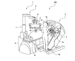
図1を参照して、手術用システム300は、たとえば、術者Qが患者側装置1を用いて人間または動物などの処置対象Rに内視鏡外科手術を施すためのシステムである。手術用システム300は、患者側装置1と、患者側装置1を操作するための操作装置2とを備える。
With reference to FIG. 1, the
術者Qは、患者側装置1に対する動作指令を操作装置2へ入力し、操作装置2は、入力された動作指令を含む指令信号を患者側装置1へ送信する。そして、患者側装置1は、操作装置2から送信された指令信号を受信し、受信した指令信号に含まれる動作指令に基づいて、自己の先端に接続された内視鏡アセンブリ4aおよび医療用処置具4bを動作させる。
The operator Q inputs an operation command for the patient-
より詳細には、操作装置2は、操作用マニピュレータ5aおよび操作ペダル5bを有する操作入力部5と、内視鏡アセンブリ4aにより撮影された画像を表示するモニタ5cとを含む。操作用マニピュレータ5aおよび操作ペダル5bは、術者Qが動作指令を入力するための機器である。
More specifically, the
術者Qは、モニタ5cにおいて表示される画像により患部を視認しながら、操作用マニピュレータ5aおよび操作ペダル5bを操作することにより、操作装置2へ動作指令を入力する。操作装置2は、入力された動作指令を含む指令信号を、有線または無線により患者側装置1へ送信する。
The operator Q inputs an operation command to the
患者側装置1は、ポジショナ7と、ポジショナ7の先端部に取り付けられたプラットホーム8と、プラットホーム8に着脱可能に取り付けられた複数のマニピュレータ3と、内視鏡アセンブリ4aと、医療用処置具4bと、患者側装置1の動作を制御するコントローラ6とを含む。
The patient-
内視鏡アセンブリ4aおよび医療用処置具4bは、マニピュレータ3に取り付けられる。コントローラ6は、操作装置2からの指令信号を受信し、受信した指令信号に基づいて、内視鏡アセンブリ4aおよび医療用処置具4bを動作させる。
The
具体的には、コントローラ6は、指令信号を受信して、当該指令信号に含まれる動作指令に基づいて、まず、ポジショナ7を動作させてプラットホーム8の位置決めを行う。また、コントローラ6は、処置対象Rの体表に留置された図示しないカニューレに対する内視鏡アセンブリ4aおよび医療用処置具4bの位置が所定の初期位置となるように、マニピュレータ3の位置決めを行う。
Specifically, the controller 6 receives the command signal and first operates the positioner 7 to position the
そして、コントローラ6は、動作指令に基づいて、内視鏡アセンブリ4aおよび医療用処置具4bを駆動するための制御信号を、マニピュレータ3経由で内視鏡アセンブリ4aおよび医療用処置具4bへ出力する。そして、内視鏡アセンブリ4aおよび医療用処置具4bは、コントローラ6から受けた制御信号に従って動作する。
Then, the controller 6 outputs a control signal for driving the
なお、コントローラ6は、ポジショナ7に内蔵されていなくてもよく、ポジショナ7とは独立した制御装置であってもよい。 The controller 6 does not have to be built in the positioner 7, and may be a control device independent of the positioner 7.
[医療用処置具の全体構成]
図2は、本発明の医療用処置具の構成を示す図である。
[Overall configuration of medical treatment tools]
FIG. 2 is a diagram showing the configuration of the medical treatment tool of the present invention.
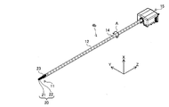
図2を参照して、医療用処置具4bは、先端部11と、シャフト12と、先端部11を操作するための複数のワイヤまたはケーブルなどの細長要素14と、細長要素14を駆動する駆動機構15とを含む。
With reference to FIG. 2, the
先端部11は、把持鉗子(グラスパ)、持針器(ニードルドライバ)、またはシザーズなどである。ここでは、先端部11が把持鉗子である場合について説明する。
The
先端部11は、エンドエフェクタ20と、特定方向、すなわち医療用処置具4bの長手方向に延びる手首部材23とを有する。エンドエフェクタ20は、たとえば2つのジョー21,22を有する。これら2つのジョー21,22は、同一の形状に形成されることにより、製造コストを低く抑えることができる。
The
シャフト12は、医療用処置具4bの長手方向に延びる筒形状を有し、矢印Aの方向に回転可能に設けられる。すなわち、シャフト12は、自己の長手方向に延びる軸(シャフト軸)を中心に回転可能に設けられる。
The
細長要素14は、たとえばタングステンまたはステンレスにより形成されており、十分な強度、屈曲性、および耐久性を有する。ステンレスはタングステンに比べて柔らかいが延びやすく、タングステンはステンレスに比べて硬いが延びにくいという性質を有する。
The
駆動機構15は、図1に示す患者側装置1におけるマニピュレータ3に取り付けられる。駆動機構15は、患者側装置1からの制御信号をマニピュレータ3経由で受けて、当該制御信号に従って、細長要素14を医療用処置具4bの長手方向に沿って動かしたり、シャフト12を矢印Aの方向に回転させたりする。
The
[先端部]
(先端部の全体構成)
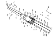
図3は、本発明の医療用処置具における先端部の構成を示す斜視図である。
[Tip]
(Overall configuration of the tip)
FIG. 3 is a perspective view showing the configuration of the tip portion of the medical treatment tool of the present invention.
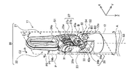
図3を参照して、先端部11は、エンドエフェクタ20および手首部材23に加えて、さらに、第1連結部31と、第2連結部32とを有する。第1連結部31および第2連結部32は、ボルトまたはネジなどである。
With reference to FIG. 3, the
以下、第1連結部31により規定される第1軸S1と平行な軸をX軸とし、第2連結部32により規定される第2軸S2と平行な軸をY軸とする。また、シャフト12により規定される第3軸(シャフト軸)S3と平行な軸をZ軸とする。
Hereinafter, the axis parallel to the first axis S1 defined by the first connecting
なお、第1軸S1の延びる方向は、第1連結部31の延びる方向と多少ずれてもよい。また、第2軸S2の延びる方向は、第2連結部32の延びる方向と多少ずれてもよい。また、第3軸S3の延びる方向は、シャフト12の延びる方向と多少ずれてもよい。
The extending direction of the first axis S1 may be slightly different from the extending direction of the first connecting
第1軸S1および第2軸S2は、エンドエフェクタ20からの平面視(Z軸の負から正の方向に見た平面視)において交差することが好ましい。すなわち、第1軸S1、第2軸S2および第3軸S3は、互いに異なる方向であることが好ましい。ここでは、第1軸S1と第2軸S2とのなす角、第1軸S1と第3軸S3とのなす角、および第2軸S2と第3軸S3とのなす角を、いずれも90度とする。 It is preferable that the first axis S1 and the second axis S2 intersect in a plan view from the end effector 20 (a plan view viewed in the negative to positive direction of the Z axis). That is, it is preferable that the first axis S1, the second axis S2, and the third axis S3 have different directions from each other. Here, the angle formed by the first axis S1 and the second axis S2, the angle formed by the first axis S1 and the third axis S3, and the angle formed by the second axis S2 and the third axis S3 are all 90. Degree.
手首部材23は、Z軸方向におけるエンドエフェクタ20側の第1端に位置するクレビス27と、Z軸方向におけるシャフト12側の第2端に位置するクレビス28とを有する。手首部材23のクレビス28は、第2連結部32を介してシャフト12の端部12aに取り付けられる。そして、手首部材23は、第2軸S2を中心に矢印Bの方向に旋回可能である。
The
ジョー21,22は、第1連結部31を介して手首部材23におけるクレビス27に取り付けられる。また、ジョー21,22は、それぞれ、指部24a,24bと、プーリ部25a,25bとを有する。プーリ部25a,25bは、第1軸S1を中心に回転可能に設けられる。また、プーリ部25a,25bの各々には、細長要素14を巻き付けるための溝が、自己の円周方向に沿って形成されている。
The
指部24aは、プーリ部25aから延びた細長形状を有し、指部24bは、プーリ部25bから延びた細長形状を有する。指部24aとプーリ部25aとは、たとえば一体に形成されている。また、指部24bとプーリ部25bとは、たとえば一体に形成されている。
The
より詳細には、指部24aは、自己の長手方向が手首部材23の長手方向と平行な姿勢、すなわちZ軸と平行な姿勢において、第1軸S1と第3軸S3とを含む面Pに対して一方側、すなわち矢印P1の示す側に位置する。また、指部24bは、自己の長手方向がZ軸と平行な姿勢において、面Pに対して他方側、すなわち矢印P2の示す側に位置する。
More specifically, the
図4は、本発明の医療用処置具における先端部の構成を示す側面図である。 FIG. 4 is a side view showing the configuration of the tip portion of the medical treatment tool of the present invention.
図4を参照して、ジョー21,22は、矢印C1および矢印C2に示すように、第1軸S1を中心に旋回することにより、互いに近づいたり、離れたり、同じ方向へ旋回したりすることができる。
With reference to FIG. 4, the
より詳細には、先端部11は、エンドエフェクタ20、手首部材23、第1連結部31、および第2連結部32に加えて、さらに、第3連結部33と、第4連結部34と、第1プーリ42aと、第2プーリ43aと、第3プーリ42bと、第4プーリ43bと、第5プーリ41とを有する。第3連結部33および第4連結部34は、ボルトまたはネジなどである。第1プーリ42a、第2プーリ43a、第3プーリ42b、および第4プーリ43bの各々は、内側プーリと外側プーリとを有する。
More specifically, the
第1プーリ42aおよび第2プーリ43aは、面Pに対して一方側、すなわち指部24aの位置する側である、矢印P1の示す側に設けられる。第3プーリ42bおよび第4プーリ43bは、面Pに対して他方側、すなわち指部24bの位置する側である、矢印P2の示す側に設けられる。第5プーリ41は、たとえば、面Pの平面上に設けられる。
The
また、第2プーリ43a、第4プーリ43b、および第5プーリ41は、第2連結部32を介してシャフト12の端部12aに取り付けられており、第2軸S2を中心に回転可能に設けられる。このように、第2プーリ43a、第4プーリ43b、および第5プーリ41が、共通の部材を介して取り付けられる構成により、部品点数を少なくすることができる。ただし、これらの回転軸は平行であれば多少ずれがあってもよく、回転軸を共通にすることが必須ではない。
Further, the
また、第1プーリ42aは、第3連結部33を介して手首部材23に取り付けられており、第3連結部33により規定される第4軸S4を中心に回転可能に設けられる。第3プーリ42bは、第4連結部34を介して手首部材23に取り付けられており、第4連結部34により規定される第5軸S5を中心に回転可能に設けられる。なお、図5に示すように、第1プーリ42aの内側プーリおよび外側プーリは、各々の回転軸が平行であるが、回転軸に多少のずれがある。また、図5に示すように、第3プーリ42bの内側プーリおよび外側プーリは、各々の回転軸が平行であるが、回転軸に多少のずれがある。
Further, the
なお、第4軸S4の延びる方向は、第3連結部33の延びる方向と多少ずれてもよい。また、第5軸S5の延びる方向は、第4連結部34の延びる方向と多少ずれてもよい。第4軸S4および第5軸S5は、面Pと交差している。たとえば、第4軸S4と面Pとのなす角、および第5軸S5と面Pとのなす角は、いずれも90度である。
The extending direction of the fourth axis S4 may be slightly different from the extending direction of the third connecting
第1プーリ42aは、自己の回転面が第2プーリ43aの回転面と略同一平面上に位置するように設けられる。また、第3プーリ42bは、自己の回転面が第4プーリ43bの回転面と略同一平面上に位置するように設けられる。たとえば、第1プーリ42a、第2プーリ43a、第3プーリ42b、および第4プーリ43bは、各々の回転面がいずれも面Pと平行になるように設けられる。
The
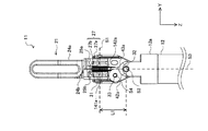
図5は、本発明の医療用処置具における先端部の構成を示す正面図である。 FIG. 5 is a front view showing the configuration of the tip portion of the medical treatment tool of the present invention.
図5を参照して、医療用処置具4bにおける先端部11は、第1連結部31から第2連結部32までの長さL1が8mm未満、たとえば7.5mmとなるように構成されている。なお、医療用処置具4bが持針器である場合、先端部11は、たとえば、長さL1が7mmとなるように構成されている。
With reference to FIG. 5, the
(先端部の詳細な構成)
再び図4を参照して、Z軸方向における手首部材23のシャフト12側の端部に位置するクレビス28は、たとえばU字形状を有し、第2連結部32の第1端側に位置する山部28aと、第2連結部32の第2端側に位置する山部28bとを有する。たとえば、山部28a,28bには、それぞれ図示しない貫通孔が形成されており、これら2つの貫通孔を第2連結部32が挿通する。
(Detailed configuration of the tip)
With reference to FIG. 4 again, the
シャフト12における端部12aもまた、U字形状を有し、2つの山部16a,16bを有する。山部16aは面Pに対して一方側である、矢印P1の示す側に設けられ、山部16bは面Pに対して他方側である、矢印P2の示す側に設けられる。そして、第2プーリ43aは、手首部材23における山部28aと、シャフト12における山部16aとの間に設けられる。また、第4プーリ43bは、手首部材23における山部28bと、シャフト12における山部16bとの間に設けられる。
The
再び図5を参照して、クレビス27は、クレビス28と同様に、たとえばU字形状を有し、第1連結部31の第1端側に位置する山部27aと、第1連結部31の第2端側に位置する山部27bとを有する。たとえば、山部27a,27bには、それぞれ図示しない貫通孔が形成されており、これら2つの貫通孔を第1連結部31が挿通する。
With reference to FIG. 5 again, the
プーリ部25aは、山部27aと山部27bとの間に、かつ山部27a側に設けられる。プーリ部25bは、山部27aと山部27bとの間に、かつ山部27b側に設けられる。
The
また、第1プーリ42aの回転軸である第4軸S4は、X軸方向において、プーリ部25aの溝よりも山部27b側に配置される。また、図4に示す第3プーリ42bの回転軸である第5軸S5は、X軸方向において、図5に示すプーリ部25bの溝よりも山部27a側に配置される。
Further, the fourth axis S4, which is the rotation axis of the
ここで、図5を参照して、仮に、第4軸S4が、山部27b側に配置される代わりに、山部27a側に配置されるとすると、プーリ部25aと第1プーリ42aとの距離が短くなるため、ジョー21が第1軸S1を中心に旋回する際、ジョー21と第1プーリ42aとが接触する可能性がある。このため、第4軸S4を山部27a側に配置する場合には、ジョー21と第1プーリ42aとの接触を避けるため、たとえば特許文献1の図7に示すように、Z軸方向における手首部材23の長さを長くして、ジョー21と第1プーリ42aとの距離を長くする必要がある。
Here, referring to FIG. 5, assuming that the fourth axis S4 is arranged on the
また、第4軸S4を山部27a側に配置する場合に、ジョー21と第1プーリ42aとの距離が近すぎると、ジョー21を旋回させるための細長要素14は、ジョー21のプーリ部25aの溝から第1プーリ42aに掛かるまでの距離が短く、Z軸に対する角度が大きくなる。このため、ジョー21を、図4に示す矢印P1の方向へ旋回させた場合に、細長要素14がプーリ部25aの溝から逸脱してしまったり、ジョー21を旋回させるための操作性が悪くなる。この観点からも、ジョー21と第1プーリ42aとの距離を長くする必要がある。
Further, when the fourth axis S4 is arranged on the
これに対して、本構成例における医療用処置具4bでは、上記のように、第4軸S4が山部27b側に配置されるため、ジョー21を旋回させたとしても、ジョー21と第1プーリ42aとが接触することがない。したがって、Z軸方向において、ジョー21と第1プーリ42aとを近づけて配置することができる。
On the other hand, in the
また、このようにZ軸方向において、ジョー21と第1プーリ42aとを近づけて配置しても、ジョー21を旋回させるための細長要素14は、ジョー21のプーリ部25aの溝から第1プーリ42aに掛かるまでの距離が長くなる。このため、細長要素14がプーリ部25aの溝から逸脱したり、ジョー21を旋回させるための操作性が悪くなることを防ぐことができる。
Further, even if the
この結果、手首部材23のZ軸方向における長さを小さくすることができ、先端部11の全体をより小型化することができる。そして、第1連結部31から第2連結部32までの長さL1を、たとえば7mm程度とすることができる。
As a result, the length of the
(細長要素の巻き掛け)
図6は、本発明の医療用処置具における先端部側の細長要素の巻き掛けの一例を示す図である。図6において、矢印Z1はシャフト軸と平行なZ軸の正の方向を示し、矢印Z2はZ軸の負の方向を示す。
(Wrapping of elongated elements)
FIG. 6 is a diagram showing an example of winding an elongated element on the tip end side in the medical treatment tool of the present invention. In FIG. 6, the arrow Z1 indicates the positive direction of the Z axis parallel to the shaft axis, and the arrow Z2 indicates the negative direction of the Z axis.
ここでは、医療用処置具4bは、3つの細長要素14を含むとする。3つの細長要素14を、それぞれ、細長要素(第1細長要素)141、細長要素(第1細長要素)142、および細長要素(第2細長要素)143とする。また、細長要素141,142,143は、それぞれ、ワイヤ141a,142a,143aと、ワイヤ141b,142b,143bとを有する。
Here, it is assumed that the
図6を参照して、医療用処置具4bの組立時において、ワイヤ141aは、プーリ部25bにガイドされた後、第1プーリ42aの外側プーリにガイドされ、第1プーリ42aと第2プーリ43aとの間の空間を通り、第2プーリ43aの外側プーリにガイドされる。
With reference to FIG. 6, at the time of assembling the
より詳細には、再び図5を参照して、ワイヤ141aは、プーリ部25bにガイドされた後、山部27a側から第1プーリ42aと第2プーリ43aとの間へ向けてガイドされる。すなわち、ワイヤ141aは、第1プーリ42aにおけるX軸の正の側の部分にガイドされながら、第1プーリ42aと第2プーリ43aとの間の空間を通り、第2プーリ43aにおけるX軸の負の側の部分にガイドされる。
More specifically, with reference to FIG. 5 again, the
再び図6を参照して、ワイヤ141bは、ワイヤ141aと同様に、プーリ部25bにガイドされた後、第3プーリ42bの内側プーリにガイドされ、第3プーリ42bと第4プーリ43bとの間の空間を通り、第4プーリ43bの内側プーリにガイドされる。ワイヤ141a,141bは、たとえば、ジョー22における指部24bに固定される。このため、ジョー22は、ワイヤ141a,141bの駆動に応じて動作する。
With reference to FIG. 6 again, the
ワイヤ142aは、ワイヤ141aと同様に、プーリ部25aにガイドされた後、第1プーリ42aの内側プーリにガイドされ、第1プーリ42aと第2プーリ43aとの間の空間を通り、第2プーリ43aの内側プーリにガイドされる。
Like the
また、ワイヤ142bは、ワイヤ141aと同様に、プーリ部25aにガイドされた後、第3プーリ42bの外側プーリにガイドされ、第3プーリ42bと第4プーリ43bとの間の空間を通り、第4プーリ43bの外側プーリにガイドされる。ワイヤ142a,142bは、たとえば、ジョー21における指部24aに固定される。このため、ジョー21は、ワイヤ142a,142bの駆動に応じて動作する。
Further, like the
ワイヤ143a,143bは、第5プーリ41に巻き付けられる。また、ワイヤ143a,143bは、たとえば、手首部材23に固定される。このため、手首部材23は、ワイヤ143a,143bの駆動に応じて動作する。
The
(細長要素の駆動に伴う先端部の動作)
細長要素141におけるワイヤ141aが矢印Z1の方向に引かれると、ジョー22は、矢印C2aの方向、すなわち第1軸S1を中心とする円の周方向であって、ジョー21へ近づく方向に旋回する。また、細長要素141におけるワイヤ141bが矢印Z1の方向に引かれると、ジョー22は、矢印C2bの方向、すなわち第1軸S1を中心とする円の周方向であって、ジョー21から離れる方向に旋回する。
(Movement of the tip when driving an elongated element)
When the
また、細長要素142におけるワイヤ142aが矢印Z1の方向に引かれると、ジョー21は、矢印C1aの方向、すなわち第1軸S1を中心とする円の周方向であって、ジョー22から離れる方向に旋回する。また、細長要素142におけるワイヤ142bが矢印Z1の方向に引かれると、ジョー21は、矢印C1bの方向、すなわち第1軸S1を中心とする円の周方向であって、ジョー22へ近づく方向に旋回する。
Further, when the
また、ワイヤ141bおよびワイヤ142aが矢印Z1の方向に同時に引かれると、ジョー21およびジョー22は、第1軸S1を中心とする円の周方向であって、互いに離れる方向に旋回する。また、ワイヤ141aおよびワイヤ142bが矢印Z1の方向に同時に引かれると、ジョー21およびジョー22は、第1軸S1を中心とする円の周方向であって、互いに近づく方向に旋回する。
Further, when the
また、ワイヤ141aおよびワイヤ142aが矢印Z1の方向に同時に引かれると、ジョー21およびジョー22の両方は、第1軸S1を中心とする円の周方向であって、矢印D1の方向に旋回する。すなわち、ジョー21は矢印C1aの方向に旋回し、ジョー22は矢印C2aの方向に旋回する。
Further, when the
また、ワイヤ141bおよびワイヤ142bが矢印Z1の方向に同時に引かれると、ジョー21およびジョー22の両方は、第1軸S1を中心とする円の周方向であって、矢印D2の方向に旋回する。すなわち、ジョー21は矢印C1bの方向に旋回し、ジョー22は矢印C2bの方向に旋回する。
Further, when the
また、ワイヤ143aが矢印Z1の方向へ引かれると、手首部材23は、矢印B2の方向、すなわち第2軸S2を中心とする円の周方向、かつY軸の負から正の方向へ見て反時計周りに旋回する。また、ワイヤ143bが矢印Z1の方向へ引かれると、手首部材23は、矢印B1の方向、すなわち第2軸S2を中心とする円の周方向、かつY軸の負から正の方向へ見て時計周りに旋回する。
Further, when the
このように、細長要素141,142,143の駆動に応じて、ジョー21、ジョー22、および手首部材23が独立して駆動する。すなわち、ジョー21,22は、第1軸S1をヨー軸として、ヨー軸を中心に回転する。また、手首部材23は、第2軸S2をピッチ軸として、ピッチ軸を中心に回転する。さらに、上述のとおり、図3に示すシャフト12は、第3軸S3をロール軸として、ロール軸を中心に回転する。
In this way, the
[先端部の変形例]
上述した先端部11は、第1軸S1を中心に旋回可能な2つのジョー21,22を有するが、このような構成に限定されない。
[Example of deformation of the tip]
The
図7は、本発明の医療用処置具における先端部の変形例の構成を示す側面図である。 FIG. 7 is a side view showing a configuration of a modified example of the tip portion of the medical treatment tool of the present invention.
図7を参照して、たとえば、先端部11におけるエンドエフェクタ60は、第1軸S1を中心に旋回可能であるジョー61と、手首部材23に固定されたジョー62とを有する。この場合、ジョー61は、第1軸S1を中心に旋回することにより、ジョー62へ近づいたり、ジョー62から離れたりすることができる。
With reference to FIG. 7, for example, the
また、医療用処置具4bが、モノポーラフックまたはモノポーラスパチュラなどである場合、エンドエフェクタ60は、ジョー61,62の代わりに、たとえば、第1軸S1を中心に旋回可能である図示しない1つのフック部、または図示しない1つのスパチュラ部を有する。
Further, when the
[駆動機構]
図8は、本発明の駆動機構の構成を示す斜視図である。
[Drive mechanism]
FIG. 8 is a perspective view showing the configuration of the drive mechanism of the present invention.
図8を参照して、駆動機構15は、ハウジング10と、ハウジング10内において回転可能に設けられた複数の駆動部材101と、ハウジング10内において回転可能に設けられた第1歯車102と、第1歯車102と係合する第2歯車103と、複数の伝達部材とを有する。図8では、駆動機構15の内部の構造を説明するため、ハウジング10の上部が外された状態を示している。
With reference to FIG. 8, the
複数の駆動部材101、および第1歯車102の各々は被伝達部材122を有し、複数の伝達部材の各々は、これら複数の被伝達部材122とそれぞれ係合する。複数の駆動部材101、および第1歯車102の各々は、基体16の表面に対して垂直な方向、すなわちX軸方向に延びる回転軸を中心に回転可能に設けられる。第2歯車103は、シャフト12の長手方向、すなわちZ軸方向に延びる回転軸を中心に回転可能に設けられる。シャフト12は、第2歯車103と係合しており、第2歯車103の回転に伴い矢印Aの方向に回転する。
Each of the plurality of driving members 101 and the
図1に示すマニピュレータ3に含まれるアクチュエータは、患者側装置1から制御信号を受けて、当該制御信号に従って、複数の伝達部材を回転させる。各々の伝達部材は、回転することにより、複数の駆動部材101、および第1歯車102のうち自己に対応する部材を回転させる。
The actuator included in the
より詳細には、駆動機構15は、3つの駆動部材101を有する。3つの駆動部材101を、それぞれ駆動部材(第1駆動部材)101A、駆動部材(第2駆動部材)101B、および駆動部材101Cとする。また、図6に示す細長要素141,142,143は、それぞれ、駆動部材101A,101B,101Cに巻き付けられる。
More specifically, the
そして、アクチュエータが、駆動部材101Aに対応する伝達部材を回転させることにより、駆動部材101Aが回転すると、駆動部材101Aに巻き付けられた細長要素141がZ軸方向に沿って動く。これにより、図3に示すジョー22が、矢印C1の方向に旋回する。
Then, when the actuator rotates the transmission member corresponding to the drive member 101A and the drive member 101A rotates, the
また、アクチュエータが、駆動部材101Bに対応する伝達部材を回転させることにより、駆動部材101Bが回転すると、駆動部材101Bに巻き付けられた細長要素142がZ軸方向に沿って動く。これにより、図3に示すジョー21が、矢印C2の方向に旋回する。
Further, when the actuator rotates the transmission member corresponding to the drive member 101B and the drive member 101B rotates, the
また、アクチュエータが、駆動部材101Cに対応する伝達部材を回転させることにより、駆動部材101Cが回転すると、駆動部材101Cに巻き付けられた細長要素143がZ軸方向に沿って動く。これにより、図3に示す手首部材23が、矢印Bの方向に旋回する。
Further, when the actuator rotates the transmission member corresponding to the drive member 101C and the drive member 101C rotates, the
また、アクチュエータが、第1歯車102に対応する伝達部材を回転させることにより、第1歯車102が回転すると、第1歯車102と係合した第2歯車103がZ軸方向に延びる回転軸を中心に回転する。そして、シャフト12が、第2歯車103の回転に伴い矢印Aの方向に回転する。
Further, when the actuator rotates the transmission member corresponding to the
[ベアリング]
再び図4を参照して、先端部11は、さらに、複数のベアリング161を有する。第2プーリ43a、第4プーリ43b、および第5プーリ41は、ベアリング161を介して、第2連結部32に取り付けられる。また、第1プーリ42aは、ベアリング161を介して、第3連結部33に取り付けられる。また、第3プーリ42bは、ベアリング161を介して、第4連結部34に取り付けられる。さらに、図3に示すプーリ部25a,25bは、図3において図示しないベアリング161を介して、第1連結部31に取り付けられる。
[bearing]
With reference to FIG. 4 again, the
ベアリング161には、一般的なベアリングを用いることができるが、たとえば以下に説明するような構成のベアリングを採用してもよい。
As the
図9は、本発明の一実施形態で用いるベアリングの構成を示す分解斜視図である。ここでは、先端部11における複数のベアリング161は、互いに同じ構成であるとする。
FIG. 9 is an exploded perspective view showing the configuration of the bearing used in one embodiment of the present invention. Here, it is assumed that the plurality of
図9を参照して、ベアリング161は、内輪部材171と、外輪部材172と、複数のボールを有する第1ボールグループ173と、複数のボールを有する第2ボールグループ174と、第1リテイナー175と、第2リテイナー176とを有する。内輪部材171、外輪部材172、第1リテイナー175、および第2リテイナー176は、リング形状を有する。
With reference to FIG. 9, the
外輪部材172の内径は、内輪部材171の外径よりも大きい。そして、外輪部材172は、自己の中心軸と、内輪部材171の中心軸とが一致した状態で、内輪部材171を内部に収容する。
The inner diameter of the
第1ボールグループ173における複数のボールは、第1リテイナー175の円周方向において等間隔に配置された状態で、第1リテイナー175に収容される。第2ボールグループ174における複数のボールは、第2リテイナー176の円周方向において等間隔に配置された状態で、第2リテイナー176に収容される。
The plurality of balls in the
たとえば、第1ボールグループ173におけるボール、および第2ボールグループ174におけるボールは、同じ個数であり、各ボールは同一の大きさを有する。また、第1リテイナー175および第2リテイナー176は同一の形状を有し、互いの中心軸が一致した状態で当接されて、内輪部材171と外輪部材172との間に設けられる。
For example, the number of balls in the
なお、ベアリング161は、第1リテイナー175または第2リテイナー176が配置される構成、すなわちリテイナーが1列配置される構成であってもよい。しかしながら、上記のように、リテイナーが2列配置される構成により、リテイナーが1列配置される場合と比較して、プーリ部25a,25b、第1プーリ42a、第2プーリ43a、第3プーリ42b、第4プーリ43b、および第5プーリ41の回転に伴いリテイナーにかかる荷重が、分散されるため、ベアリング161の耐久性が向上し、医療用処置具4bの使用回数および使用時間を増大させることができる。
The
また、たとえば、第1ボールグループ173における各ボールと、第2ボールグループ174における各ボールとは、第1リテイナー175および第2リテイナー176の周方向において交互に配置される。さらに、第1ボールグループ173における各ボールの一部分は、第2リテイナー176に収容され、第2ボールグループ174における各ボールの一部分は、第1リテイナー175に収容される。
Further, for example, each ball in the
このような構成により、ベアリング161の幅Wが大きくなることを防ぐことができる。このため、プーリ部25a,25b、第1プーリ42a、第2プーリ43a、第3プーリ42b、第4プーリ43b、および第5プーリ41と、複数のベアリング161との、それぞれの接触部分における摩擦が大きくなることを防ぐことができる。
With such a configuration, it is possible to prevent the width W of the bearing 161 from becoming large. Therefore, the friction between the
なお、上記のような構成のベアリングを、プーリ部25a,25b、第1プーリ42a、第2プーリ43a、第3プーリ42b、第4プーリ43b、および第5プーリ41の全てのプーリ部分に用いる場合について説明したが、一部のプーリ部分にのみ、上記のような構成のベアリングを用いてもよい。たとえば、細長要素14によるテンションがかかった状態で操作されることの多い第1プーリ42aおよび第3プーリ42bにのみ、上記のような構成のベアリングを用いてもよい。
When the bearing having the above configuration is used for all the pulley portions of the
本パートで説明した特徴は、以下のように要約できる。 The features described in this part can be summarized as follows.
[1]医療用処置具に用いられるベアリングであって、リング形状を有する内輪部材と、 リング形状を有し、径の大きさが前記内輪部材の径より大きい外輪部材と、複数の第1ボールを含む第1ボールグループと、複数の第2ボールを含む第2ボールグループと、リング形状を有し、前記複数の第1ボールを収容する第1リテイナーと、リング形状を有し、前記複数の第2ボールを収容する第2リテイナーとを備え、前記第1リテイナーおよび前記第2リテイナーは、各々の中心軸が一致した状態で当接されて、前記内輪部材と前記外輪部材との間に設けられる、ベアリング。 [1] Bearings used in medical treatment tools, an inner ring member having a ring shape, an outer ring member having a ring shape and having a diameter larger than the diameter of the inner ring member, and a plurality of first balls. A first ball group including, a second ball group including a plurality of second balls, a first retainer having a ring shape and accommodating the plurality of first balls, and the plurality of ring-shaped retainers. A second retainer for accommodating the second ball is provided, and the first retainer and the second retainer are brought into contact with each other in a state where their central axes are aligned with each other, and are provided between the inner ring member and the outer ring member. Bearings.
[2]前記第1ボールおよび前記第2ボールは、前記第1リテイナーおよび前記第2リテイナーの周方向において交互に配置される、[1]に記載のベアリング。 [2] The bearing according to [1], wherein the first ball and the second ball are alternately arranged in the circumferential direction of the first retainer and the second retainer.
[3]前記第1ボールの一部分は、前記第2リテイナーに収容され、前記第2ボールの一部分は、前記第1リテイナーに収容される、[1]または[2]に記載のベアリング。 [3] The bearing according to [1] or [2], wherein a part of the first ball is housed in the second retainer and a part of the second ball is housed in the first retainer.
[4][1]から[3]のいずれか1つに記載のベアリングと、プーリ部を含むエンドエフェクタと、前記プーリ部によってガイドされ、前記エンドエフェクタを操作するための細長要素と、前記細長要素をガイドする第2プーリおよび第3プーリとを備え、前記ベアリングは、前記第2プーリおよび前記第3プーリの少なくともいずれか一方に取り付けられる、医療用処置具。 [4] The bearing according to any one of [1] to [3], an end effector including a pulley portion, an elongated element guided by the pulley portion for operating the end effector, and the elongated element. A medical treatment tool comprising a second pulley and a third pulley for guiding an element, the bearing being attached to at least one of the second pulley and the third pulley.
[細長要素と先端部の各部材との固定]
図10は、本発明の医療用処置具における手首部材と第5プーリとの接続関係を示す図である。
[Fixing of elongated elements and each member at the tip]
FIG. 10 is a diagram showing a connection relationship between the wrist member and the fifth pulley in the medical treatment tool of the present invention.
図10を参照して、上述のとおり、手首部材23におけるクレビス28を挿通する第2連結部32を介して、第5プーリ41が、手首部材23に取り付けられる。第5プーリ41には、外周の一部に凹部41aが形成されている。また、手首部材23には、第5プーリ41に形成された凹部41aと対向する位置に凹部23aが形成されている。
With reference to FIG. 10, as described above, the
細長要素143は、ワイヤ143aおよびワイヤ143bに加えて、さらに、凸部143cを有する。凸部143cは、たとえば円柱形状を有し、ワイヤ143aとワイヤ143bとを連結する。第5プーリ41に形成された凹部41a、および手首部材23に形成された凹部23aは、細長要素143の凸部143cの一部と係合可能に構成されている。
The
医療用処置具4bの組立時において、作業者は、凹部41aおよび凹部23aに細長要素143の凸部143cを係合させる。これにより、手首部材23に細長要素143を容易に固定することができる。
At the time of assembling the
そして、手首部材23に細長要素143が固定された状態において、細長要素143におけるワイヤ143aまたはワイヤ143bがZ軸方向に引かれると、凸部143cは、第2軸S2を中心に第5プーリ41の外周に沿って動き、これにより、第5プーリ41は、凸部143cと共に第2軸S2を中心に回転する。
Then, in a state where the
また、この場合、凸部143cに係合した手首部材23における凹部23aは、第2軸S2を中心に第5プーリ41の外周に沿って動き、これにより、手首部材23は、矢印Bの方向、すなわち第2軸S2を中心とする円の周方向に旋回する。
Further, in this case, the
なお、ジョー22と細長要素141とを固定するための構成、およびジョー21と細長要素142とを固定するための構成に、上記のような凸部を有する細長要素14を用いてもよい。
The
図11は、本発明の医療用処置具におけるジョーとプーリ部との接続関係を示す図である。 FIG. 11 is a diagram showing a connection relationship between a jaw and a pulley portion in the medical treatment tool of the present invention.
図11に示すように、たとえば、プーリ部25aは、外周の一部に凹部25a1が形成されている。また、細長要素142は、たとえば円柱形状の凸部142cを有し、プーリ部25aに形成された凹部25a1が、当該凸部142cの一部と係合する。
As shown in FIG. 11, for example, the
なお、ジョー22とプーリ部25bとの接続関係は、図11に示すジョー21とプーリ部25aとの接続関係と同様であるとする。
It is assumed that the connection relationship between the
上記のような構成であれば、先端部11の組み立て時において、凹部25a1に凸部142cを係合させることによりジョー21に細長要素142を固定することができるため、先端部11の組み立て作業を容易化させることができる。
With the above configuration, when assembling the
凸部142c,143cの形状は円柱形状に限らず、また対応する凹部41a,25a1は円形の一部分の形状の切欠きでなくてもよく、凸部と凹部が係合可能であれば、たとえば、凸部142c,143cの形状が立方体であり、凹部41a,25a1が立方体と係合可能な形状の切欠きであってもよい。
The shapes of the
(変形例)
図12は、手首部材と第5プーリとの接続関係の変形例を示す図である。
(Modification example)
FIG. 12 is a diagram showing a modified example of the connection relationship between the wrist member and the fifth pulley.
図12に示すように、細長要素143は、凸部143cを有する代わりに、たとえば、ワイヤ143a,143bの端部に設けられた円柱状の幅広部143a1,143b1を有してもよい。この場合、幅広部143a1,143b1は、手首部材23に形成されたスロット23b1,23b2に係合される。
As shown in FIG. 12, the
しかしながら、このような構成では、万が一細長要素143が切れてしまった場合に細長要素143が体腔内へと飛び出してしまう可能性がある。また、このような構成では、手首部材23に細長要素143を固定するためには、幅広部143a1,143b1をスロット23b1,23b2にそれぞれ係合させる必要がある。
However, in such a configuration, in the unlikely event that the
これに対して、図10に示すような構成では、万が一細長要素143が切れてしまった場合に細長要素143が体腔内へと飛び出してしまうことがなく、さらに手首部材23に細長要素143を固定する作業が容易である。このため、図10に示すような構成により細長要素143を固定することが好ましい。
On the other hand, in the configuration as shown in FIG. 10, in the unlikely event that the
なお、これまで説明してきた先端部11に、図10に示すような構成を適用することは必須ではなく、図12のような構成の採用を排除するものではない。
It is not essential to apply the configuration shown in FIG. 10 to the
本パートで説明した特徴は、以下のように要約できる。 The features described in this part can be summarized as follows.
[1]特定方向に延びる手首部材と、前記特定方向における前記手首部材の第1端に、第1連結部を介して取り付けられるエンドエフェクタと、シャフトと、前記手首部材を操作するための細長要素と、前記細長要素をガイドするプーリとを備え、前記手首部材は、前記特定方向における前記第1端と反対側の第2端が、第2連結部を介して前記シャフトの端部に取り付けられ、前記プーリは、前記第2連結部を中心に回転可能であり、前記細長要素は、凸部を有し、前記凸部は、前記プーリに形成された凹部、および前記手首部材における前記第2端に形成された凹部の両方に係合される、医療用処置具。 [1] A wrist member extending in a specific direction, an end effector attached to the first end of the wrist member in the specific direction via a first connecting portion, a shaft, and an elongated element for operating the wrist member. And a pulley for guiding the elongated element, the wrist member has a second end opposite to the first end in the specific direction attached to the end of the shaft via a second connecting portion. The pulley is rotatable about the second connecting portion, the elongated element has a convex portion, and the convex portion is a concave portion formed in the pulley and the second portion in the wrist member. A medical treatment device that engages with both recesses formed on the edges.
[2]プーリ部を有するエンドエフェクタと、前記プーリ部によってガイドされ、前記エンドエフェクタを操作するための細長要素とを備え、前記細長要素は凸部を有し、前記凸部は前記プーリに形成された凹部に係合される、医療用処置具。 [2] An end effector having a pulley portion and an elongated element guided by the pulley portion for operating the end effector are provided, the elongated element has a convex portion, and the convex portion is formed on the pulley. A medical treatment tool that engages with a recess.
[細長要素の伸び対策]
図13は、本発明の医療用処置具における細長要素の構成の例1を示す図である。
[Countermeasures against elongation of elongated elements]
FIG. 13 is a diagram showing an example 1 of the configuration of an elongated element in the medical treatment tool of the present invention.
図13を参照して、医療用処置具4bは、さらに、細長要素14の一部分を覆う硬性チューブ13を含む。細長要素14は、ステンレスまたはタングステンなどの材質により、たとえば、直径0.45mmのワイヤ状またはケーブル状により形成されているため、長期間における繰り返しの使用により伸びてしまうことがある。
With reference to FIG. 13, the
このため、細長要素14の少なくとも一部を、細長要素14と比較して十分に固く伸びない硬性チューブ13で覆うことにより、伸びの影響を受ける細長要素14の長さを実質的に短くし、細長要素14の伸びによる影響を減少させている。硬性チューブ13は、たとえばステンレスなどの材質により形成されているが、直径1.06mm程度のパイプ形状に形成されることにより、長期間使用された場合であっても伸びは生じない。
Therefore, by covering at least a part of the
本構成例における硬性チューブ13の長手方向における第1端13aおよび第2端13bの少なくとも一方は、面取り加工されている。具体的には、第1端13aおよび第2端13bの両方は、滑らかな面を有するように、丸みを持つように形成されているか、またはテーパー状に形成されている。
At least one of the
このような構成により、細長要素14の駆動による先端部11の動作が複雑である場合でも、硬性チューブ13の角が細長要素14に当接することによる細長要素14の損傷を防ぐことができる。
With such a configuration, even when the operation of the
図14は、本発明の医療用処置具における細長要素の構成の例2を示す図である。 FIG. 14 is a diagram showing an example 2 of the configuration of an elongated element in the medical treatment tool of the present invention.
図14に示す医療用処置具4bは、細長要素14を硬性チューブ13で被覆する代わりに、細長要素14の中間部分に、硬質部材により形成されたロッド17を用いている。この場合、たとえば、細長要素14は、Z軸の負の側に設けられる先端部側ワイヤ241と、Z軸の正の側に設けられる駆動機構側ワイヤ242とを有する。
In the
そして、ロッド17の長手方向における第1端17aに先端部側ワイヤ241が連結され、ロッド17の長手方向における第2端17bに駆動機構側ワイヤ242が連結される。そして、ロッド17の第1端17aおよび第2端17bの少なくとも一方は、面取り加工されている。具体的には、第1端17aおよび第2端17bの両方は、滑らかな面を有するように、丸みを持つように形成されているか、またはテーパー状に形成されている。
Then, the tip
ここで、細長要素14は、図8に示す駆動機構15に設けられた駆動部材101に巻き付けられて、テンションの調節が行われる。そして、細長要素14は、テンションが掛けられた状態が続くため、テンションの掛かる方向、すなわちZ軸方向に伸びる可能性がある。これに対して、上記のように、ロッド17を用いる構成により、ロッド17の長さの分だけ、細長要素14の長さを短くすることができるため、細長要素14の伸びる長さを短くすることができる。
Here, the
本パートで説明した特徴は、以下のように要約できる。 The features described in this part can be summarized as follows.
[1]プーリ部を有するエンドエフェクタと、前記プーリ部によってガイドされ、前記エンドエフェクタを操作するための細長要素と、前記細長要素を駆動する駆動部材とを備え、 前記細長要素は、一部分が硬性チューブによって被覆され、前記硬性チューブは、自己の長手方向における両端部のうちの少なくとも一方の端部が面取り加工されている、医療用処置具。 [1] An end effector having a pulley portion, an elongated element guided by the pulley portion for operating the end effector, and a driving member for driving the elongated element are provided, and the elongated element is partially rigid. A medical treatment tool covered with a tube, wherein the rigid tube is chamfered at least one end of both ends in its longitudinal direction.
[2]前記硬性チューブにおける前記両端部のうちの少なくとも一方の端部は、テーパー状に形成されている、[1]に記載の医療用処置具。 [2] The medical treatment tool according to [1], wherein at least one end of the both ends of the rigid tube is formed in a tapered shape.
なお、これまで説明してきた先端部11に本特徴を適用することは必須ではなく、面取り加工されていない硬性チューブまたはロッドを用いることを排除するものではない。
It is not essential to apply this feature to the
上記実施の形態は、すべての点で例示であって制限的なものではないと考えられるべきである。本発明の範囲は、上記説明ではなく特許請求の範囲によって示され、特許請求の範囲と均等の意味および範囲内でのすべての変更が含まれることが意図される。 It should be considered that the above embodiments are exemplary in all respects and not restrictive. The scope of the present invention is shown by the scope of claims rather than the above description, and is intended to include all modifications within the meaning and scope equivalent to the scope of claims.
4b 医療用処置具
13 硬性チューブ
14,141,142,143 細長要素
143c 凸部
20 エンドエフェクタ
21,22 ジョー
23 手首部材
23a 凹部
31 第1連結部
32 第2連結部
41 第5プーリ
41a 凹部
42a 第1プーリ
42b 第3プーリ
43a 第2プーリ
43b 第4プーリ
161 ベアリング
171 内輪部材
172 外輪部材
173 第1ボールグループ
174 第2ボールグループ
175 第1リテイナー
176 第2リテイナー
4b
Claims (15)
特定方向に延び、前記特定方向における第1端側において第1連結部を介して前記第1のプーリ部および前記第2のプーリ部が回転可能に取り付けられる手首部材と、
シャフト軸を有し、前記手首部材の前記特定方向における前記第1端と反対側の第2端が第2連結部を介して回転可能に取り付けられるシャフトと、
前記手首部材に取り付けられる第1プーリと、
前記特定方向に関して前記第1プーリよりも前記手首部材の第2端側に配置され、前記第2連結部により規定される第2軸と平行な回転軸を有する第2プーリとを備え、
前記第1のプーリ部は、前記第1のプーリ部の回転軸である第1軸の軸方向において前記第1連結部の第1端側に配置され、かつ自己の円周方向に沿う溝が形成され、
前記第2のプーリ部は、前記第1軸の軸方向において前記第1連結部の第1端側とは反対側の第2端側に配置され、
前記第1プーリおよび前記第2プーリは、前記エンドエフェクタの長手方向および前記手首部材の前記特定方向が前記シャフト軸と平行となる姿勢において、前記シャフト軸および前記第1軸を含む面に対して一方側で、且つ、前記第1指部の位置する側に配置され、
前記第1プーリの回転軸および前記第2プーリの回転軸は、前記面と交差し、
前記第1プーリの回転軸は、前記第1軸の軸方向において前記第1連結部の第1端よりも前記第1連結部の第2端に近い側に配置される、医療用処置具。 A first jaw including a first pulley portion and a first finger portion extending from the first pulley portion, and a second jaw including a second pulley portion and a second finger portion extending from the second pulley portion. And, including end effectors,
A wrist member that extends in a specific direction and is rotatably attached to the first pulley portion and the second pulley portion via a first connecting portion on the first end side in the specific direction.
A shaft having a shaft shaft and rotatably attached to a second end of the wrist member opposite to the first end in the specific direction via a second connecting portion.
The first pulley attached to the wrist member and
A second pulley which is arranged on the second end side of the wrist member with respect to the specific direction and has a rotation axis parallel to the second axis defined by the second connecting portion is provided.
The first pulley portion is arranged on the first end side of the first connecting portion in the axial direction of the first axis, which is the rotation axis of the first pulley portion, and has a groove along its own circumferential direction. Formed,
The second pulley portion is arranged on the second end side opposite to the first end side of the first connecting portion in the axial direction of the first axis.
The first pulley and the second pulley are in a posture in which the longitudinal direction of the end effector and the specific direction of the wrist member are parallel to the shaft axis with respect to the surface including the shaft axis and the first axis. It is arranged on one side and on the side where the first finger portion is located.
The rotation axis of the first pulley and the rotation axis of the second pulley intersect the surface,
The rotary shaft of the first pulley, the Ru is arranged closer to the second end of the first connecting portion than the first end of the first connecting portion in the axial direction of the first axis, a medical treatment tool.
前記手首部材に取り付けられる第3プーリと、
前記特定方向に関して前記第3プーリよりも前記手首部材の第2端側に配置され、前記第2軸と平行な回転軸を有する第4プーリとを備え、
前記第2のプーリ部は、自己の円周方向に沿う溝が形成され、
前記第3プーリ、前記第4プーリ、および前記第2指部は、前記面に対して前記一方側とは反対の他方側に位置し、
前記第3プーリの回転軸および前記第4プーリの回転軸は、前記面と交差し、
前記第3プーリの回転軸は、前記第1軸の軸方向において前記第1連結部の第2端よりも前記第1連結部の第1端に近い側に配置される、請求項1に記載の医療用処置具。 The medical treatment tool further
A third pulley attached to the wrist member,
A fourth pulley which is arranged on the second end side of the wrist member with respect to the specific direction and has a rotation axis parallel to the second axis is provided .
The second pulley portion before SL, a groove along the self circumferential direction are formed,
Before Symbol third pulley, said fourth pulley, and the second finger is positioned on the other side opposite to said one side with respect to said face,
The rotation axis of the third pulley and the rotation axis of the fourth pulley intersect the surface,
The rotation axis of the third pulley, Ru is disposed closer to the first end of the first connecting portion than the second end of the first connecting portion in the axial direction of the first axis, according to claim 1 Medical treatment tool.
前記第1のジョーを操作するための第1細長要素を備え、
前記第1細長要素は、前記第1のプーリ部によってガイドされ、さらに、前記第1連結部の第1端側から前記第1プーリと前記第2プーリとの間へ向けて、前記間を通るようにガイドされる、請求項1または請求項2に記載の医療用処置具。 The medical treatment tool further
A first elongated element for operating the first jaw is provided.
The first elongated element is guided by the first pulley portion, and further passes between the first pulley portion and the second pulley portion from the first end side of the first connecting portion. The medical treatment device according to claim 1 or 2 , which is guided as described above.
前記ベアリングを含む前記第1プーリおよび/または前記第2プーリは、
リング形状を有する内輪部材と、
リング形状を有し、径の大きさが前記内輪部材の径より大きい外輪部材と、
複数の第1ボールを含む第1ボールグループと、
複数の第2ボールを含む第2ボールグループと、
リング形状を有し、前記複数の第1ボールを収容する第1リテイナーと、
リング形状を有し、前記複数の第2ボールを収容する第2リテイナーとを有し、
前記第1リテイナーおよび前記第2リテイナーは、各々の中心軸が一致した状態で当接されて、前記内輪部材と前記外輪部材との間に設けられる、請求項1から請求項4のいずれか1項に記載の医療用処置具。 The first pulley and / or the second pulley includes bearings.
The first pulley and / or the second pulley including the bearing
An inner ring member with a ring shape and
An outer ring member having a ring shape and having a diameter larger than the diameter of the inner ring member,
A first ball group containing a plurality of first balls,
A second ball group containing multiple second balls,
A first retainer having a ring shape and accommodating the plurality of first balls,
It has a ring shape and has a second retainer for accommodating the plurality of second balls.
Any one of claims 1 to 4 , wherein the first retainer and the second retainer are brought into contact with each other in a state where their central axes are aligned and are provided between the inner ring member and the outer ring member. Medical treatment tools described in the section.
前記第2ボールの一部分は、前記第1リテイナーに収容される、請求項5または請求項6に記載の医療用処置具。 A part of the first ball is housed in the second retainer.
The medical treatment tool according to claim 5 or 6 , wherein a part of the second ball is housed in the first retainer.
前記ベアリングを含む前記第3プーリおよび/または前記第4プーリは、
リング形状を有する内輪部材と、
リング形状を有し、径の大きさが前記内輪部材の径より大きい外輪部材と、
複数の第1ボールを含む第1ボールグループと、
複数の第2ボールを含む第2ボールグループと、
リング形状を有し、前記複数の第1ボールを収容する第1リテイナーと、
リング形状を有し、前記複数の第2ボールを収容する第2リテイナーとを有し、
前記第1リテイナーおよび前記第2リテイナーは、各々の中心軸が一致した状態で当接されて、前記内輪部材と前記外輪部材との間に設けられる、請求項2に記載の医療用処置具。 The third pulley and / or the fourth pulley includes bearings.
The third pulley and / or the fourth pulley including the bearing
An inner ring member with a ring shape and
An outer ring member having a ring shape and having a diameter larger than the diameter of the inner ring member,
A first ball group containing a plurality of first balls,
A second ball group containing multiple second balls,
A first retainer having a ring shape and accommodating the plurality of first balls,
It has a ring shape and has a second retainer for accommodating the plurality of second balls.
The medical treatment tool according to claim 2 , wherein the first retainer and the second retainer are brought into contact with each other in a state where their central axes are aligned and are provided between the inner ring member and the outer ring member.
前記第1のジョーを操作するための第1細長要素と、
前記第2のジョーを操作するための第2細長要素と、
前記手首部材を操作するための第3細長要素とを備える、請求項1から請求項8のいずれか1項に記載の医療用処置具。 The medical treatment tool
The first elongated element for operating the first jaw and
A second elongated element for operating the second jaw,
The medical treatment tool according to any one of claims 1 to 8 , further comprising a third elongated element for operating the wrist member.
前記硬性チューブの長手方向における両端部のうちの少なくとも一方の端部が、面取り加工されている、請求項9に記載の医療用処置具。 At least one portion of the first elongated element , the second elongated element and the third elongated element is coated with a rigid tube.
The medical treatment tool according to claim 9 , wherein at least one end of both ends of the rigid tube in the longitudinal direction is chamfered.
前記第3細長要素をガイドし、かつ前記第2軸を中心に回転可能である第5プーリを備え、
前記第3細長要素は、凸部を有し、
前記凸部は、前記第5プーリに形成された凹部、および前記手首部材の第2端に形成された凹部の両方に係合される、請求項9から請求項11のいずれか1項に記載の医療用処置具。 The medical treatment tool further
A fifth pulley that guides the third elongated element and is rotatable about the second axis is provided.
The third elongated element has a convex portion and has a convex portion.
The one according to any one of claims 9 to 11 , wherein the convex portion is engaged with both a concave portion formed in the fifth pulley and a concave portion formed in the second end of the wrist member. Medical treatment tool.
前記凸部は、前記第1のジョーに形成された凹部に係合される、請求項9から請求項12のいずれか1項に記載の医療用処置具。 The first elongated element has a convex portion and has a convex portion.
The medical treatment tool according to any one of claims 9 to 12, wherein the convex portion is engaged with a concave portion formed in the first jaw.
前記第1細長要素、前記第2細長要素および前記第3細長要素をそれぞれ駆動する第1駆動部材、第2駆動部材および第3駆動部材を備え、
第1駆動部材、前記第2駆動部材および第3駆動部材は、それぞれ、伝達部材と係合する被伝達部材を含む、請求項9から請求項13のいずれか1項に記載の医療用処置具。 The medical treatment tool further
A first driving member , a second driving member, and a third driving member for driving the first elongated element , the second elongated element, and the third elongated element , respectively, are provided.
The medical treatment tool according to any one of claims 9 to 13, wherein the first driving member, the second driving member, and the third driving member each include a transmitted member that engages with the transmitting member. ..
前記伝達部材を動作させるアクチュエータを含むマニピュレータとを備える、手術用システム。 The medical treatment tool according to claim 14,
A surgical system comprising a manipulator including an actuator for operating the transmission member.
Priority Applications (7)
| Application Number | Priority Date | Filing Date | Title |
|---|---|---|---|
| JP2017091235A JP6894752B2 (en) | 2017-05-01 | 2017-05-01 | Medical treatment tools and surgical systems |
| CN201810390248.1A CN108836483B (en) | 2017-05-01 | 2018-04-27 | Medical treatment tool and surgical system |
| EP18169795.4A EP3395279A1 (en) | 2017-05-01 | 2018-04-27 | Medical treatment tool and surgical system |
| US15/964,672 US11071600B2 (en) | 2017-05-01 | 2018-04-27 | Medical treatment tool and surgical system |
| JP2020013477A JP6975273B2 (en) | 2017-05-01 | 2020-01-30 | Surgical systems and medical treatment tools |
| US16/782,061 US20200170728A1 (en) | 2017-05-01 | 2020-02-05 | Medical treatment tool and surgical system |
| US16/782,070 US20200170729A1 (en) | 2017-05-01 | 2020-02-05 | Medical treatment tool and surgical system |
Applications Claiming Priority (1)
| Application Number | Priority Date | Filing Date | Title |
|---|---|---|---|
| JP2017091235A JP6894752B2 (en) | 2017-05-01 | 2017-05-01 | Medical treatment tools and surgical systems |
Related Child Applications (2)
| Application Number | Title | Priority Date | Filing Date |
|---|---|---|---|
| JP2020013477A Division JP6975273B2 (en) | 2017-05-01 | 2020-01-30 | Surgical systems and medical treatment tools |
| JP2020013480A Division JP2020062541A (en) | 2020-01-30 | 2020-01-30 | Medical treatment device and surgical system |
Publications (3)
| Publication Number | Publication Date |
|---|---|
| JP2018187029A JP2018187029A (en) | 2018-11-29 |
| JP2018187029A5 JP2018187029A5 (en) | 2020-01-09 |
| JP6894752B2 true JP6894752B2 (en) | 2021-06-30 |
Family
ID=62116222
Family Applications (1)
| Application Number | Title | Priority Date | Filing Date |
|---|---|---|---|
| JP2017091235A Active JP6894752B2 (en) | 2017-05-01 | 2017-05-01 | Medical treatment tools and surgical systems |
Country Status (4)
| Country | Link |
|---|---|
| US (3) | US11071600B2 (en) |
| EP (1) | EP3395279A1 (en) |
| JP (1) | JP6894752B2 (en) |
| CN (1) | CN108836483B (en) |
Families Citing this family (6)
| Publication number | Priority date | Publication date | Assignee | Title |
|---|---|---|---|---|
| JP7009428B2 (en) | 2019-09-26 | 2022-01-25 | 株式会社メディカロイド | Surgical instruments |
| JP7306225B2 (en) | 2019-10-31 | 2023-07-11 | 株式会社アイシン | toilet seat device |
| JP6815679B2 (en) * | 2020-08-18 | 2021-01-20 | リバーフィールド株式会社 | Surgical tool |
| KR102308214B1 (en) | 2020-12-09 | 2021-10-05 | 주식회사 리브스메드 | End tool for Surgical instrument and manufacturing method thereof |
| CN112617968B (en) * | 2020-12-31 | 2022-08-26 | 杭州康基医疗器械有限公司 | Surgical forceps head structure capable of rotating in multiple directions |
| JPWO2023135793A1 (en) * | 2022-01-17 | 2023-07-20 |
Family Cites Families (22)
| Publication number | Priority date | Publication date | Assignee | Title |
|---|---|---|---|---|
| JPS53105010U (en) * | 1977-01-25 | 1978-08-24 | ||
| US6398726B1 (en) * | 1998-11-20 | 2002-06-04 | Intuitive Surgical, Inc. | Stabilizer for robotic beating-heart surgery |
| US6394998B1 (en) | 1999-01-22 | 2002-05-28 | Intuitive Surgical, Inc. | Surgical tools for use in minimally invasive telesurgical applications |
| US6902560B1 (en) * | 2000-07-27 | 2005-06-07 | Intuitive Surgical, Inc. | Roll-pitch-roll surgical tool |
| JP3944172B2 (en) * | 2004-01-27 | 2007-07-11 | オリンパス株式会社 | Surgical instrument |
| US7935130B2 (en) | 2006-11-16 | 2011-05-03 | Intuitive Surgical Operations, Inc. | Two-piece end-effectors for robotic surgical tools |
| EP3375479B1 (en) * | 2007-05-18 | 2023-03-22 | Boston Scientific Scimed, Inc. | Medical drive systems |
| US8758342B2 (en) | 2007-11-28 | 2014-06-24 | Covidien Ag | Cordless power-assisted medical cauterization and cutting device |
| US8540748B2 (en) * | 2008-07-07 | 2013-09-24 | Intuitive Surgical Operations, Inc. | Surgical instrument wrist |
| US8821480B2 (en) * | 2008-07-16 | 2014-09-02 | Intuitive Surgical Operations, Inc. | Four-cable wrist with solid surface cable channels |
| US9204923B2 (en) * | 2008-07-16 | 2015-12-08 | Intuitive Surgical Operations, Inc. | Medical instrument electronically energized using drive cables |
| US20100168721A1 (en) | 2008-12-30 | 2010-07-01 | Intuitive Surgical, Inc. | Lubricating tendons in a tendon-actuated surgical instrument |
| JP2011045500A (en) | 2009-08-26 | 2011-03-10 | Terumo Corp | Medical manipulator |
| JP2011200593A (en) * | 2010-03-26 | 2011-10-13 | Terumo Corp | Medical instrument |
| CN202520781U (en) | 2012-02-29 | 2012-11-07 | 张亚军 | Bearing with non-symmetrical pockets |
| JP5951345B2 (en) * | 2012-05-01 | 2016-07-13 | Hoya株式会社 | Endoscope snare |
| US9351754B2 (en) | 2012-06-29 | 2016-05-31 | Ethicon Endo-Surgery, Llc | Ultrasonic surgical instruments with distally positioned jaw assemblies |
| WO2014030110A1 (en) | 2012-08-21 | 2014-02-27 | Chinmay Deodhar | Wristed surgical instrument capable of multiple functions, without requiring extra inputs |
| US9889568B2 (en) | 2013-03-14 | 2018-02-13 | Sri International | Compact robotic wrist |
| WO2016080180A1 (en) * | 2014-11-18 | 2016-05-26 | オリンパス株式会社 | Endoscopic treatment instrument |
| GB201521803D0 (en) | 2015-12-10 | 2016-01-27 | Cambridge Medical Robotics Ltd | Surgical instrument articulation |
| GB201521805D0 (en) | 2015-12-10 | 2016-01-27 | Cambridge Medical Robotics Ltd | Guiding engagement of a robot arm and surgical instrument |
-
2017
- 2017-05-01 JP JP2017091235A patent/JP6894752B2/en active Active
-
2018
- 2018-04-27 CN CN201810390248.1A patent/CN108836483B/en not_active Expired - Fee Related
- 2018-04-27 EP EP18169795.4A patent/EP3395279A1/en not_active Withdrawn
- 2018-04-27 US US15/964,672 patent/US11071600B2/en active Active
-
2020
- 2020-02-05 US US16/782,070 patent/US20200170729A1/en not_active Abandoned
- 2020-02-05 US US16/782,061 patent/US20200170728A1/en not_active Abandoned
Also Published As
| Publication number | Publication date |
|---|---|
| CN108836483B (en) | 2021-05-14 |
| EP3395279A1 (en) | 2018-10-31 |
| US20200170728A1 (en) | 2020-06-04 |
| CN108836483A (en) | 2018-11-20 |
| US11071600B2 (en) | 2021-07-27 |
| US20180311000A1 (en) | 2018-11-01 |
| US20200170729A1 (en) | 2020-06-04 |
| JP2018187029A (en) | 2018-11-29 |
Similar Documents
| Publication | Publication Date | Title |
|---|---|---|
| JP6894752B2 (en) | Medical treatment tools and surgical systems | |
| JP6961733B2 (en) | Mechanical wrist joints, related devices, and methods with improved range of motion | |
| US10888306B2 (en) | Operating self-antagonistic drives of medical instruments | |
| US20230000574A1 (en) | Passive preload and capstan drive for surgical instruments | |
| US11576735B2 (en) | Controllable steerable instrument | |
| JP6811676B2 (en) | Drive member, drive mechanism, and manufacturing method of drive mechanism | |
| KR102571618B1 (en) | Robotic Microsurgery Assembly | |
| US20180214220A1 (en) | Surgical robot | |
| US20180242991A1 (en) | Surgical instrument with increased actuation force | |
| WO2017006373A1 (en) | Joint for robot arm, and surgical instrument | |
| JP6836649B2 (en) | Medical treatment tools and surgical systems | |
| JP4145309B2 (en) | Treatment tool | |
| CN111970985A (en) | Low friction small medical tool with easily assembled components | |
| JP2008220972A (en) | Treatment instrument | |
| JP2008220971A (en) | Treatment instrument | |
| US11457904B2 (en) | Reduced diameter steerable instrument | |
| JP6975273B2 (en) | Surgical systems and medical treatment tools | |
| US20200390507A1 (en) | Low-friction medical tools having roller-assisted tension members | |
| JP2020062541A (en) | Medical treatment device and surgical system | |
| JP6895007B2 (en) | Medical treatment tool | |
| JPWO2020105616A1 (en) | Bending mechanism and medical equipment |
Legal Events
| Date | Code | Title | Description |
|---|---|---|---|
| A521 | Request for written amendment filed |
Free format text: JAPANESE INTERMEDIATE CODE: A523 Effective date: 20170519 |
|
| A521 | Request for written amendment filed |
Free format text: JAPANESE INTERMEDIATE CODE: A523 Effective date: 20191114 |
|
| A621 | Written request for application examination |
Free format text: JAPANESE INTERMEDIATE CODE: A621 Effective date: 20191114 |
|
| A977 | Report on retrieval |
Free format text: JAPANESE INTERMEDIATE CODE: A971007 Effective date: 20200421 |
|
| A131 | Notification of reasons for refusal |
Free format text: JAPANESE INTERMEDIATE CODE: A131 Effective date: 20200609 |
|
| A521 | Request for written amendment filed |
Free format text: JAPANESE INTERMEDIATE CODE: A523 Effective date: 20200717 |
|
| A131 | Notification of reasons for refusal |
Free format text: JAPANESE INTERMEDIATE CODE: A131 Effective date: 20201201 |
|
| A521 | Request for written amendment filed |
Free format text: JAPANESE INTERMEDIATE CODE: A523 Effective date: 20210127 |
|
| TRDD | Decision of grant or rejection written | ||
| A01 | Written decision to grant a patent or to grant a registration (utility model) |
Free format text: JAPANESE INTERMEDIATE CODE: A01 Effective date: 20210601 |
|
| A61 | First payment of annual fees (during grant procedure) |
Free format text: JAPANESE INTERMEDIATE CODE: A61 Effective date: 20210604 |
|
| R150 | Certificate of patent or registration of utility model |
Ref document number: 6894752 Country of ref document: JP Free format text: JAPANESE INTERMEDIATE CODE: R150 |