EP3374245B1 - Caisse pour véhicule ferroviaire de transport de passagers - Google Patents
Caisse pour véhicule ferroviaire de transport de passagers Download PDFInfo
- Publication number
- EP3374245B1 EP3374245B1 EP17705137.2A EP17705137A EP3374245B1 EP 3374245 B1 EP3374245 B1 EP 3374245B1 EP 17705137 A EP17705137 A EP 17705137A EP 3374245 B1 EP3374245 B1 EP 3374245B1
- Authority
- EP
- European Patent Office
- Prior art keywords
- car body
- connecting beam
- section
- vehicle floor
- vehicle
- Prior art date
- Legal status (The legal status is an assumption and is not a legal conclusion. Google has not performed a legal analysis and makes no representation as to the accuracy of the status listed.)
- Active
Links
- 239000002184 metal Substances 0.000 claims description 13
- 230000007704 transition Effects 0.000 claims description 11
- 239000011324 bead Substances 0.000 claims description 9
- XLYOFNOQVPJJNP-UHFFFAOYSA-N water Substances O XLYOFNOQVPJJNP-UHFFFAOYSA-N 0.000 claims description 8
- 238000000034 method Methods 0.000 claims description 2
- 238000010276 construction Methods 0.000 description 2
- 230000001010 compromised effect Effects 0.000 description 1
- 238000009833 condensation Methods 0.000 description 1
- 230000005494 condensation Effects 0.000 description 1
- 230000008878 coupling Effects 0.000 description 1
- 238000010168 coupling process Methods 0.000 description 1
- 238000005859 coupling reaction Methods 0.000 description 1
- 230000005489 elastic deformation Effects 0.000 description 1
- 239000000463 material Substances 0.000 description 1
- 230000002787 reinforcement Effects 0.000 description 1
- 230000000717 retained effect Effects 0.000 description 1
- 239000007787 solid Substances 0.000 description 1
Images

Classifications
-
- B—PERFORMING OPERATIONS; TRANSPORTING
- B61—RAILWAYS
- B61D—BODY DETAILS OR KINDS OF RAILWAY VEHICLES
- B61D17/00—Construction details of vehicle bodies
- B61D17/04—Construction details of vehicle bodies with bodies of metal; with composite, e.g. metal and wood body structures
- B61D17/10—Floors
-
- B—PERFORMING OPERATIONS; TRANSPORTING
- B61—RAILWAYS
- B61F—RAIL VEHICLE SUSPENSIONS, e.g. UNDERFRAMES, BOGIES OR ARRANGEMENTS OF WHEEL AXLES; RAIL VEHICLES FOR USE ON TRACKS OF DIFFERENT WIDTH; PREVENTING DERAILING OF RAIL VEHICLES; WHEEL GUARDS, OBSTRUCTION REMOVERS OR THE LIKE FOR RAIL VEHICLES
- B61F1/00—Underframes
- B61F1/08—Details
- B61F1/10—End constructions
-
- B—PERFORMING OPERATIONS; TRANSPORTING
- B61—RAILWAYS
- B61D—BODY DETAILS OR KINDS OF RAILWAY VEHICLES
- B61D15/00—Other railway vehicles, e.g. scaffold cars; Adaptations of vehicles for use on railways
- B61D15/06—Buffer cars; Arrangements or construction of railway vehicles for protecting them in case of collisions
-
- B—PERFORMING OPERATIONS; TRANSPORTING
- B61—RAILWAYS
- B61F—RAIL VEHICLE SUSPENSIONS, e.g. UNDERFRAMES, BOGIES OR ARRANGEMENTS OF WHEEL AXLES; RAIL VEHICLES FOR USE ON TRACKS OF DIFFERENT WIDTH; PREVENTING DERAILING OF RAIL VEHICLES; WHEEL GUARDS, OBSTRUCTION REMOVERS OR THE LIKE FOR RAIL VEHICLES
- B61F1/00—Underframes
- B61F1/08—Details
- B61F1/14—Attaching or supporting vehicle body-structure
Definitions
- the invention relates to a car body for a passenger rail vehicle.
- Such a passenger rail vehicle is, for example, from US 2015/047530 A1 known.
- Rail vehicles in particular passenger vehicles, are mostly produced today as self-supporting metal structures.
- a vehicle body is built up from an underframe, end walls and a roof.
- the underframe must withstand the operating forces, especially the loading, clutch pressure and tensile forces.
- the underframe is often designed as a frame construction and usually comprises two external longitudinal members and possibly a central longitudinal member as well as several cross members connecting the longitudinal members and is reinforced at the ends of the vehicle. This reinforcement takes place by means of so-called end pieces at the vehicle end and main cross members, which also include the bearings of the bogies (or individual axles).
- end pieces at the vehicle end and main cross members, which also include the bearings of the bogies (or individual axles).
- the invention is therefore based on the object of specifying a car body for a passenger rail vehicle which, even with high axial pressure forces, only has low stress peaks on components of the underframe, in particular at the transition between the vehicle floor and the front end.
- the basic idea of the invention is a car body for a passenger rail vehicle, comprising an underframe with a front end at each end of the vehicle, the underframe comprising two external longitudinal members, between which a vehicle floor is arranged, the vehicle floor being made of profiled sheet metal with a trapezoidal cross-section, with the The corrugation of the profile sheet extends in the longitudinal direction of the Car body extend constructed, the vehicle floor being firmly connected to the respective front structure at the transition points to one of the front structures by means of a connecting beam oriented transversely to the longitudinal direction of the car body, and the connecting beam being designed as a profiled sheet with a substantially L-shaped cross-section, and where the with a stem connected section of the connecting beam is equipped with a trapezoidal bead.
- the connecting beam is essentially designed with an L-shaped cross section and is attached to the vehicle floor and the front end by means of welded connections.
- welded connections in particular the welded connection to the front end, are subject to particularly high constraining forces when the car body is deformed, so that their durability can be endangered.
- connection beam which has a higher elasticity, so that the constraining forces due to the deformation of the car body are significantly reduced. In this way, both the main dimensions and the wall thicknesses and materials of the connecting beam can be retained.
- the connecting beam On the side facing the front end, the corresponding leg of the L-shaped cross-section, the connecting beam is equipped with a feature that increases the elasticity.
- This section is designed with a trapezoidal bead, so that the moment of resistance of the connecting beam is greatly reduced.
- the connecting support is equipped with recesses through which a section of the vehicle floor can be passed. In this way, a particularly firm connection to the vehicle floor can be established, since the length of the weld seam connecting the connection beam to the vehicle floor is increased.
- connection carrier It is advantageous to equip the connection carrier with at least one water drainage hole, so that in the Water collected in cavities in the vehicle floor can drain away.
- connection carrier can be constructed from a plurality of individual metal sheets that are welded to one another.
- a second embodiment provides for the connection carrier to be produced from a single sheet metal (in one piece) by means of a forming process.
- Fig. 1 shows an example and schematically a cross section through a vehicle floor.
- a section is shown transversely to the longitudinal direction of a rail vehicle, further components, such as a central longitudinal support or transverse support, not being shown for the sake of simplicity.
- the underframe of the vehicle comprises two external longitudinal members 1, between which a vehicle floor 2 is arranged.
- the vehicle floor 2 is typically welded to the side members and is designed as a so-called trapezoidal sheet.
- This trapezoidal sheet consists of sheet metal with a trapezoidal edge in cross section, the beads of the profiled sheet extending in the longitudinal direction of the car body.
- Fig. 2 shows by way of example and schematically a vehicle floor at the point of transition to a front end with a conventional connection beam according to the prior art. It shows a section along the longitudinal direction of a rail vehicle through the undercarriage.
- the vehicle floor 2 made of trapezoidal sheet metal ends at this transition point and is connected to the front end 4 of the vehicle.
- a connection beam 3 of conventional design is provided, oriented transversely to the longitudinal axis of the vehicle, which essentially has an L-shaped cross section and which is firmly and permanently connected to both the vehicle floor 2 and the front end 6, typically by means of welded connections.
- connection beam 3 of conventional design is provided with recesses which allow a partial passage of the vehicle floor 2 through a section of the connection beam 3, so that a welded connection can be produced at this connection point with high strength.
- the weld seam 6 for connecting the connecting beam 3 to the front end 4 is subjected to very high loads, since a twisting of the front end 4 with respect to the vehicle floor 2 occurs with high axial loads.
- the small wall thickness of the connecting beam 3 compared to the front structure 4 also increases the probability of failure of the weld 6.
- Fig. 3 shows an example and schematically a vehicle floor at the point of transition to a front end with a
- connection beam 5 is inserted between the vehicle floor 2 and the front end 4.
- This connection carrier 5 is equipped with a bead 7 in a trapezoidal shape. This bead significantly reduces the moment of resistance of the connection carrier against deformations due to the introduction of torque at high axial loads, so that the connection carrier 5 can be more easily deformed and the load on the weld seam 6 is significantly reduced.
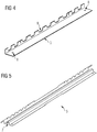
- Fig. 4 shows by way of example and schematically a conventional connection carrier.
- An oblique view of a connection carrier 3 is shown as it is shown, for example, in a FIG Fig. 2 application shown can be used.
- the connection carrier 3 has an essentially L-shaped cross section, one section being equipped with recesses 9. Furthermore, the connection carrier 3 comprises two water drainage bores 8.
- Fig. 5 shows an example and schematically a connection beam.
- An oblique view of a connection carrier 5 according to the invention is shown as it is, for example, in a FIG Fig. 3 application shown can be used.
- the connection carrier 5 has an essentially L-shaped cross section, one section being equipped with recesses 9.
- the second section of the connecting beam 5 is designed with a trapezoidal bead 7.
Claims (4)
- Châssis de véhicule pour véhicule ferroviaire de transport de passagers, comportant une bogie comprenant un avant-corps (4) chacun à chaque extrémité du véhicule, dans lequel la bogie comporte deux longerons extérieurs (1) entre lesquels un plancher de véhicule (2) est disposé, le plancher de véhicule (2) étant réalisé en tôle profilée pliée en section à la manière d'un trapèze, les moulures de la tôle profilée s'étendant au sens longitudinal du châssis de véhicule, et dans lequel le plancher de véhicule (2) est solidaire, aux transitions vers l'une chacune des avant-corps (4), à l'avant-corps respectif, grâce à une poutre de liaison (5) orientée transversalement au sens longitudinal du châssis de véhicule, et dans lequel la poutre de liaison (5) est réalisée sous forme d'une tôle profilée à section transversale sensiblement sous forme L, caractérisé en ce que le tronçon de la poutre de liaison (5) relié à un avant-corps (4) est muni d'une moulure trapézoïdale (7) et dans lequel la poutre de liaison (5) présente des évidements (9) à travers lesquels passe un tronçon du plancher de véhicule (2) .
- Châssis de véhicule pour véhicule ferroviaire de transport de passagers selon l'une des revendications 1 ou 2,
caractérisé en ce que la poutre de liaison (5) comporte au moins un alésage d'évacuation d'eau (8). - Châssis de véhicule pour véhicule ferroviaire de transport de passagers selon l'une des revendications 1 à 3,
caractérisé en ce que la poutre de liaison (5) est constituée par plusieurs tôles individuelles soudées l'une à l'autre. - Châssis de véhicule pour véhicule ferroviaire de transport de passagers selon l'une des revendications 1 à 3,
caractérisé en ce que la poutre de liaison (5) est réalisée sous forme monobloc à partir d'une seule tôle grâce à un procédé de formage.
Priority Applications (1)
| Application Number | Priority Date | Filing Date | Title |
|---|---|---|---|
| PL17705137T PL3374245T3 (pl) | 2016-02-17 | 2017-02-15 | Pudło wagonu do pasażerskiego pojazdu szynowego |
Applications Claiming Priority (2)
| Application Number | Priority Date | Filing Date | Title |
|---|---|---|---|
| ATA50105/2016A AT518382B1 (de) | 2016-02-17 | 2016-02-17 | Wagenkasten für ein Passagierschienenfahrzeug |
| PCT/EP2017/053384 WO2017140717A1 (fr) | 2016-02-17 | 2017-02-15 | Caisse pour véhicule ferroviaire de transport de passagers |
Publications (2)
| Publication Number | Publication Date |
|---|---|
| EP3374245A1 EP3374245A1 (fr) | 2018-09-19 |
| EP3374245B1 true EP3374245B1 (fr) | 2021-05-12 |
Family
ID=58044087
Family Applications (1)
| Application Number | Title | Priority Date | Filing Date |
|---|---|---|---|
| EP17705137.2A Active EP3374245B1 (fr) | 2016-02-17 | 2017-02-15 | Caisse pour véhicule ferroviaire de transport de passagers |
Country Status (6)
| Country | Link |
|---|---|
| US (1) | US10906563B2 (fr) |
| EP (1) | EP3374245B1 (fr) |
| CN (1) | CN108602520B (fr) |
| AT (1) | AT518382B1 (fr) |
| PL (1) | PL3374245T3 (fr) |
| WO (1) | WO2017140717A1 (fr) |
Family Cites Families (12)
| Publication number | Priority date | Publication date | Assignee | Title |
|---|---|---|---|---|
| DE4008703A1 (de) * | 1990-03-17 | 1991-09-19 | Audi Ag | Tragstruktur fuer ein kraftfahrzeug |
| JPH05254429A (ja) | 1992-03-13 | 1993-10-05 | Tokyu Car Corp | 鉄道車両用台枠 |
| FR2691937B1 (fr) * | 1992-06-03 | 1994-07-22 | Alsthom Gec | Caisse de vehicule ferroviaire en acier inoxydable. |
| JP3562795B2 (ja) | 2000-08-29 | 2004-09-08 | 川崎重工業株式会社 | 二重構造の側梁による鉄道車両の車体フレーム |
| CN201516856U (zh) * | 2009-10-16 | 2010-06-30 | 青岛四方庞巴迪铁路运输设备有限公司 | 铁路客车底架端部结构 |
| CN201580395U (zh) | 2009-10-30 | 2010-09-15 | 青岛四方庞巴迪铁路运输设备有限公司 | 轨道车辆不锈钢车体底架结构 |
| AT511291A1 (de) * | 2011-04-04 | 2012-10-15 | Siemens Ag Oesterreich | Schienenfahrzeug mit angesetzter verformungszone |
| AT511290A1 (de) * | 2011-04-04 | 2012-10-15 | Siemens Ag Oesterreich | Schienenfahrzeug mit verformungszone |
| JP5931548B2 (ja) * | 2012-04-02 | 2016-06-08 | 川崎重工業株式会社 | 鉄道車両 |
| CN104354711A (zh) * | 2014-11-12 | 2015-02-18 | 南车二七车辆有限公司 | 一种拼接式铁路货车中梁 |
| CN204956497U (zh) * | 2015-08-11 | 2016-01-13 | 南车眉山车辆有限公司 | 一种铁路货车鱼腹梁底架 |
| JP6647907B2 (ja) * | 2016-02-18 | 2020-02-14 | 日本車輌製造株式会社 | 鉄道車両構体 |
-
2016
- 2016-02-17 AT ATA50105/2016A patent/AT518382B1/de not_active IP Right Cessation
-
2017
- 2017-02-15 PL PL17705137T patent/PL3374245T3/pl unknown
- 2017-02-15 US US15/999,272 patent/US10906563B2/en active Active
- 2017-02-15 WO PCT/EP2017/053384 patent/WO2017140717A1/fr active Application Filing
- 2017-02-15 EP EP17705137.2A patent/EP3374245B1/fr active Active
- 2017-02-15 CN CN201780012085.7A patent/CN108602520B/zh active Active
Non-Patent Citations (1)
| Title |
|---|
| None * |
Also Published As
| Publication number | Publication date |
|---|---|
| PL3374245T3 (pl) | 2021-11-02 |
| CN108602520A (zh) | 2018-09-28 |
| US10906563B2 (en) | 2021-02-02 |
| AT518382A1 (de) | 2017-09-15 |
| EP3374245A1 (fr) | 2018-09-19 |
| AT518382B1 (de) | 2017-12-15 |
| US20190106129A1 (en) | 2019-04-11 |
| WO2017140717A1 (fr) | 2017-08-24 |
| CN108602520B (zh) | 2021-02-09 |
Similar Documents
| Publication | Publication Date | Title |
|---|---|---|
| DE102010014302A1 (de) | Luftfahrzeug und Befestigungsanordnung für eine Fußbodenstruktur in einem Luftfahrzeug | |
| DE102008057196A1 (de) | Achsträger | |
| DE102009026458A1 (de) | Strukturbauteil und Herstellungsverfahren für ein Strukturbauteil | |
| DE102008008246A1 (de) | Buchsenlager mit verringertem Bauraumbedarf | |
| DE102005003978A1 (de) | Karosserie-Bauteil eines Kraftfahrzeuges | |
| DE102013010332A1 (de) | Sandwichbauteil mit Verstärkungsprofil | |
| EP2563635A1 (fr) | Longeron renforcé pour un véhicule sur rails | |
| DE102019109554A1 (de) | Biegefederelement aus einem Faserkunststoffverbundmaterial | |
| DE102015008261A1 (de) | Aufprallträger, Seitentür und Fahrzeug | |
| DE102012207901A1 (de) | Fahrzeugkarosserie mit einem Knoten | |
| DE102008024585A1 (de) | Federelement für eine Feder-Dämpfer-Anordnung | |
| WO2011038751A1 (fr) | Longeron pour véhicules ferroviaires | |
| DE102011115855A1 (de) | Faserverbundlängsträger | |
| DE102010062748B4 (de) | Kraftfahrzeugkarosserie mit einem Bodenblech und einem Seitenschweller | |
| DE102010053734A1 (de) | Vorrichtung zum Ausbilden eines Lagers | |
| DE102013222016A1 (de) | Verfahren zum Herstellen eines verstärkten Faserverbundbauteils in Schalenbauweise | |
| DE102010027354A1 (de) | Tragstruktur einer Fahrzeugkarosserie | |
| DE102013215323A1 (de) | Befestigungselement für ein Karosserieteil und Befestigungssystem mit Befestigungselement | |
| EP3374245B1 (fr) | Caisse pour véhicule ferroviaire de transport de passagers | |
| DE102012001054A1 (de) | Knickstrebe für ein Fahrwerk | |
| DE102019126375A1 (de) | Stützstrukturmodul für einen Wagenkasten | |
| DE102015225760A1 (de) | Trägerelement, Kraftfahrzeug mit einem Trägerelement und Verfahren zur Herstellung eines Trägerelements | |
| DE102017003024A1 (de) | Abschlusselement zur Krafteinleitung in ein vorgefertigtes Faserkunststoffverbundrohr | |
| DE102011113742A1 (de) | Träger | |
| DE102013222970A1 (de) | Verfahren zum Verbinden zweier Bauteile, Verbindungsabschnitt eines Bauteils und Bauteilverbund |
Legal Events
| Date | Code | Title | Description |
|---|---|---|---|
| STAA | Information on the status of an ep patent application or granted ep patent |
Free format text: STATUS: UNKNOWN |
|
| STAA | Information on the status of an ep patent application or granted ep patent |
Free format text: STATUS: THE INTERNATIONAL PUBLICATION HAS BEEN MADE |
|
| PUAI | Public reference made under article 153(3) epc to a published international application that has entered the european phase |
Free format text: ORIGINAL CODE: 0009012 |
|
| STAA | Information on the status of an ep patent application or granted ep patent |
Free format text: STATUS: REQUEST FOR EXAMINATION WAS MADE |
|
| 17P | Request for examination filed |
Effective date: 20180615 |
|
| AK | Designated contracting states |
Kind code of ref document: A1 Designated state(s): AL AT BE BG CH CY CZ DE DK EE ES FI FR GB GR HR HU IE IS IT LI LT LU LV MC MK MT NL NO PL PT RO RS SE SI SK SM TR |
|
| AX | Request for extension of the european patent |
Extension state: BA ME |
|
| DAV | Request for validation of the european patent (deleted) | ||
| DAX | Request for extension of the european patent (deleted) | ||
| RAP1 | Party data changed (applicant data changed or rights of an application transferred) |
Owner name: SIEMENS MOBILITY GMBH |
|
| RAP1 | Party data changed (applicant data changed or rights of an application transferred) |
Owner name: SIEMENS MOBILITY AUSTRIA GMBH |
|
| GRAP | Despatch of communication of intention to grant a patent |
Free format text: ORIGINAL CODE: EPIDOSNIGR1 |
|
| STAA | Information on the status of an ep patent application or granted ep patent |
Free format text: STATUS: GRANT OF PATENT IS INTENDED |
|
| INTG | Intention to grant announced |
Effective date: 20201218 |
|
| GRAS | Grant fee paid |
Free format text: ORIGINAL CODE: EPIDOSNIGR3 |
|
| GRAA | (expected) grant |
Free format text: ORIGINAL CODE: 0009210 |
|
| STAA | Information on the status of an ep patent application or granted ep patent |
Free format text: STATUS: THE PATENT HAS BEEN GRANTED |
|
| AK | Designated contracting states |
Kind code of ref document: B1 Designated state(s): AL AT BE BG CH CY CZ DE DK EE ES FI FR GB GR HR HU IE IS IT LI LT LU LV MC MK MT NL NO PL PT RO RS SE SI SK SM TR |
|
| REG | Reference to a national code |
Ref country code: GB Ref legal event code: FG4D Free format text: NOT ENGLISH |
|
| REG | Reference to a national code |
Ref country code: CH Ref legal event code: EP |
|
| REG | Reference to a national code |
Ref country code: DE Ref legal event code: R096 Ref document number: 502017010336 Country of ref document: DE |
|
| REG | Reference to a national code |
Ref country code: IE Ref legal event code: FG4D Free format text: LANGUAGE OF EP DOCUMENT: GERMAN |
|
| REG | Reference to a national code |
Ref country code: AT Ref legal event code: REF Ref document number: 1392012 Country of ref document: AT Kind code of ref document: T Effective date: 20210615 |
|
| REG | Reference to a national code |
Ref country code: LT Ref legal event code: MG9D |
|
| REG | Reference to a national code |
Ref country code: NL Ref legal event code: MP Effective date: 20210512 |
|
| PG25 | Lapsed in a contracting state [announced via postgrant information from national office to epo] |
Ref country code: FI Free format text: LAPSE BECAUSE OF FAILURE TO SUBMIT A TRANSLATION OF THE DESCRIPTION OR TO PAY THE FEE WITHIN THE PRESCRIBED TIME-LIMIT Effective date: 20210512 Ref country code: LT Free format text: LAPSE BECAUSE OF FAILURE TO SUBMIT A TRANSLATION OF THE DESCRIPTION OR TO PAY THE FEE WITHIN THE PRESCRIBED TIME-LIMIT Effective date: 20210512 Ref country code: HR Free format text: LAPSE BECAUSE OF FAILURE TO SUBMIT A TRANSLATION OF THE DESCRIPTION OR TO PAY THE FEE WITHIN THE PRESCRIBED TIME-LIMIT Effective date: 20210512 Ref country code: BG Free format text: LAPSE BECAUSE OF FAILURE TO SUBMIT A TRANSLATION OF THE DESCRIPTION OR TO PAY THE FEE WITHIN THE PRESCRIBED TIME-LIMIT Effective date: 20210812 |
|
| PG25 | Lapsed in a contracting state [announced via postgrant information from national office to epo] |
Ref country code: GR Free format text: LAPSE BECAUSE OF FAILURE TO SUBMIT A TRANSLATION OF THE DESCRIPTION OR TO PAY THE FEE WITHIN THE PRESCRIBED TIME-LIMIT Effective date: 20210813 Ref country code: IS Free format text: LAPSE BECAUSE OF FAILURE TO SUBMIT A TRANSLATION OF THE DESCRIPTION OR TO PAY THE FEE WITHIN THE PRESCRIBED TIME-LIMIT Effective date: 20210912 Ref country code: LV Free format text: LAPSE BECAUSE OF FAILURE TO SUBMIT A TRANSLATION OF THE DESCRIPTION OR TO PAY THE FEE WITHIN THE PRESCRIBED TIME-LIMIT Effective date: 20210512 Ref country code: PT Free format text: LAPSE BECAUSE OF FAILURE TO SUBMIT A TRANSLATION OF THE DESCRIPTION OR TO PAY THE FEE WITHIN THE PRESCRIBED TIME-LIMIT Effective date: 20210913 Ref country code: NO Free format text: LAPSE BECAUSE OF FAILURE TO SUBMIT A TRANSLATION OF THE DESCRIPTION OR TO PAY THE FEE WITHIN THE PRESCRIBED TIME-LIMIT Effective date: 20210812 Ref country code: RS Free format text: LAPSE BECAUSE OF FAILURE TO SUBMIT A TRANSLATION OF THE DESCRIPTION OR TO PAY THE FEE WITHIN THE PRESCRIBED TIME-LIMIT Effective date: 20210512 Ref country code: SE Free format text: LAPSE BECAUSE OF FAILURE TO SUBMIT A TRANSLATION OF THE DESCRIPTION OR TO PAY THE FEE WITHIN THE PRESCRIBED TIME-LIMIT Effective date: 20210512 |
|
| PG25 | Lapsed in a contracting state [announced via postgrant information from national office to epo] |
Ref country code: NL Free format text: LAPSE BECAUSE OF FAILURE TO SUBMIT A TRANSLATION OF THE DESCRIPTION OR TO PAY THE FEE WITHIN THE PRESCRIBED TIME-LIMIT Effective date: 20210512 |
|
| PG25 | Lapsed in a contracting state [announced via postgrant information from national office to epo] |
Ref country code: ES Free format text: LAPSE BECAUSE OF FAILURE TO SUBMIT A TRANSLATION OF THE DESCRIPTION OR TO PAY THE FEE WITHIN THE PRESCRIBED TIME-LIMIT Effective date: 20210512 Ref country code: RO Free format text: LAPSE BECAUSE OF FAILURE TO SUBMIT A TRANSLATION OF THE DESCRIPTION OR TO PAY THE FEE WITHIN THE PRESCRIBED TIME-LIMIT Effective date: 20210512 Ref country code: EE Free format text: LAPSE BECAUSE OF FAILURE TO SUBMIT A TRANSLATION OF THE DESCRIPTION OR TO PAY THE FEE WITHIN THE PRESCRIBED TIME-LIMIT Effective date: 20210512 Ref country code: DK Free format text: LAPSE BECAUSE OF FAILURE TO SUBMIT A TRANSLATION OF THE DESCRIPTION OR TO PAY THE FEE WITHIN THE PRESCRIBED TIME-LIMIT Effective date: 20210512 Ref country code: SK Free format text: LAPSE BECAUSE OF FAILURE TO SUBMIT A TRANSLATION OF THE DESCRIPTION OR TO PAY THE FEE WITHIN THE PRESCRIBED TIME-LIMIT Effective date: 20210512 Ref country code: SM Free format text: LAPSE BECAUSE OF FAILURE TO SUBMIT A TRANSLATION OF THE DESCRIPTION OR TO PAY THE FEE WITHIN THE PRESCRIBED TIME-LIMIT Effective date: 20210512 |
|
| REG | Reference to a national code |
Ref country code: DE Ref legal event code: R097 Ref document number: 502017010336 Country of ref document: DE |
|
| PLBE | No opposition filed within time limit |
Free format text: ORIGINAL CODE: 0009261 |
|
| STAA | Information on the status of an ep patent application or granted ep patent |
Free format text: STATUS: NO OPPOSITION FILED WITHIN TIME LIMIT |
|
| 26N | No opposition filed |
Effective date: 20220215 |
|
| PG25 | Lapsed in a contracting state [announced via postgrant information from national office to epo] |
Ref country code: IS Free format text: LAPSE BECAUSE OF FAILURE TO SUBMIT A TRANSLATION OF THE DESCRIPTION OR TO PAY THE FEE WITHIN THE PRESCRIBED TIME-LIMIT Effective date: 20210912 Ref country code: AL Free format text: LAPSE BECAUSE OF FAILURE TO SUBMIT A TRANSLATION OF THE DESCRIPTION OR TO PAY THE FEE WITHIN THE PRESCRIBED TIME-LIMIT Effective date: 20210512 |
|
| PG25 | Lapsed in a contracting state [announced via postgrant information from national office to epo] |
Ref country code: IT Free format text: LAPSE BECAUSE OF FAILURE TO SUBMIT A TRANSLATION OF THE DESCRIPTION OR TO PAY THE FEE WITHIN THE PRESCRIBED TIME-LIMIT Effective date: 20210512 |
|
| PG25 | Lapsed in a contracting state [announced via postgrant information from national office to epo] |
Ref country code: MC Free format text: LAPSE BECAUSE OF FAILURE TO SUBMIT A TRANSLATION OF THE DESCRIPTION OR TO PAY THE FEE WITHIN THE PRESCRIBED TIME-LIMIT Effective date: 20210512 |
|
| REG | Reference to a national code |
Ref country code: BE Ref legal event code: MM Effective date: 20220228 |
|
| PG25 | Lapsed in a contracting state [announced via postgrant information from national office to epo] |
Ref country code: LU Free format text: LAPSE BECAUSE OF NON-PAYMENT OF DUE FEES Effective date: 20220215 |
|
| PG25 | Lapsed in a contracting state [announced via postgrant information from national office to epo] |
Ref country code: IE Free format text: LAPSE BECAUSE OF NON-PAYMENT OF DUE FEES Effective date: 20220215 |
|
| PG25 | Lapsed in a contracting state [announced via postgrant information from national office to epo] |
Ref country code: BE Free format text: LAPSE BECAUSE OF NON-PAYMENT OF DUE FEES Effective date: 20220228 |
|
| PGFP | Annual fee paid to national office [announced via postgrant information from national office to epo] |
Ref country code: FR Payment date: 20230221 Year of fee payment: 7 Ref country code: CZ Payment date: 20230206 Year of fee payment: 7 Ref country code: AT Payment date: 20230109 Year of fee payment: 7 |
|
| PGFP | Annual fee paid to national office [announced via postgrant information from national office to epo] |
Ref country code: TR Payment date: 20230214 Year of fee payment: 7 Ref country code: PL Payment date: 20230203 Year of fee payment: 7 Ref country code: GB Payment date: 20230308 Year of fee payment: 7 Ref country code: DE Payment date: 20220620 Year of fee payment: 7 |
|
| PGFP | Annual fee paid to national office [announced via postgrant information from national office to epo] |
Ref country code: CH Payment date: 20230504 Year of fee payment: 7 |
|
| PG25 | Lapsed in a contracting state [announced via postgrant information from national office to epo] |
Ref country code: HU Free format text: LAPSE BECAUSE OF FAILURE TO SUBMIT A TRANSLATION OF THE DESCRIPTION OR TO PAY THE FEE WITHIN THE PRESCRIBED TIME-LIMIT; INVALID AB INITIO Effective date: 20170215 |
|
| PGFP | Annual fee paid to national office [announced via postgrant information from national office to epo] |
Ref country code: AT Payment date: 20240109 Year of fee payment: 8 |