EP3374245B1 - Car body for a passenger rail vehicle - Google Patents
Car body for a passenger rail vehicle Download PDFInfo
- Publication number
- EP3374245B1 EP3374245B1 EP17705137.2A EP17705137A EP3374245B1 EP 3374245 B1 EP3374245 B1 EP 3374245B1 EP 17705137 A EP17705137 A EP 17705137A EP 3374245 B1 EP3374245 B1 EP 3374245B1
- Authority
- EP
- European Patent Office
- Prior art keywords
- car body
- connecting beam
- section
- vehicle floor
- vehicle
- Prior art date
- Legal status (The legal status is an assumption and is not a legal conclusion. Google has not performed a legal analysis and makes no representation as to the accuracy of the status listed.)
- Active
Links
- 239000002184 metal Substances 0.000 claims description 13
- 230000007704 transition Effects 0.000 claims description 11
- 239000011324 bead Substances 0.000 claims description 9
- XLYOFNOQVPJJNP-UHFFFAOYSA-N water Substances O XLYOFNOQVPJJNP-UHFFFAOYSA-N 0.000 claims description 8
- 238000000034 method Methods 0.000 claims description 2
- 238000010276 construction Methods 0.000 description 2
- 230000001010 compromised effect Effects 0.000 description 1
- 238000009833 condensation Methods 0.000 description 1
- 230000005494 condensation Effects 0.000 description 1
- 230000008878 coupling Effects 0.000 description 1
- 238000010168 coupling process Methods 0.000 description 1
- 238000005859 coupling reaction Methods 0.000 description 1
- 230000005489 elastic deformation Effects 0.000 description 1
- 239000000463 material Substances 0.000 description 1
- 230000002787 reinforcement Effects 0.000 description 1
- 230000000717 retained effect Effects 0.000 description 1
- 239000007787 solid Substances 0.000 description 1
Images

Classifications
-
- B—PERFORMING OPERATIONS; TRANSPORTING
- B61—RAILWAYS
- B61D—BODY DETAILS OR KINDS OF RAILWAY VEHICLES
- B61D17/00—Construction details of vehicle bodies
- B61D17/04—Construction details of vehicle bodies with bodies of metal; with composite, e.g. metal and wood body structures
- B61D17/10—Floors
-
- B—PERFORMING OPERATIONS; TRANSPORTING
- B61—RAILWAYS
- B61F—RAIL VEHICLE SUSPENSIONS, e.g. UNDERFRAMES, BOGIES OR ARRANGEMENTS OF WHEEL AXLES; RAIL VEHICLES FOR USE ON TRACKS OF DIFFERENT WIDTH; PREVENTING DERAILING OF RAIL VEHICLES; WHEEL GUARDS, OBSTRUCTION REMOVERS OR THE LIKE FOR RAIL VEHICLES
- B61F1/00—Underframes
- B61F1/08—Details
- B61F1/10—End constructions
-
- B—PERFORMING OPERATIONS; TRANSPORTING
- B61—RAILWAYS
- B61D—BODY DETAILS OR KINDS OF RAILWAY VEHICLES
- B61D15/00—Other railway vehicles, e.g. scaffold cars; Adaptations of vehicles for use on railways
- B61D15/06—Buffer cars; Arrangements or construction of railway vehicles for protecting them in case of collisions
-
- B—PERFORMING OPERATIONS; TRANSPORTING
- B61—RAILWAYS
- B61F—RAIL VEHICLE SUSPENSIONS, e.g. UNDERFRAMES, BOGIES OR ARRANGEMENTS OF WHEEL AXLES; RAIL VEHICLES FOR USE ON TRACKS OF DIFFERENT WIDTH; PREVENTING DERAILING OF RAIL VEHICLES; WHEEL GUARDS, OBSTRUCTION REMOVERS OR THE LIKE FOR RAIL VEHICLES
- B61F1/00—Underframes
- B61F1/08—Details
- B61F1/14—Attaching or supporting vehicle body-structure
Definitions
- the invention relates to a car body for a passenger rail vehicle.
- Such a passenger rail vehicle is, for example, from US 2015/047530 A1 known.
- Rail vehicles in particular passenger vehicles, are mostly produced today as self-supporting metal structures.
- a vehicle body is built up from an underframe, end walls and a roof.
- the underframe must withstand the operating forces, especially the loading, clutch pressure and tensile forces.
- the underframe is often designed as a frame construction and usually comprises two external longitudinal members and possibly a central longitudinal member as well as several cross members connecting the longitudinal members and is reinforced at the ends of the vehicle. This reinforcement takes place by means of so-called end pieces at the vehicle end and main cross members, which also include the bearings of the bogies (or individual axles).
- end pieces at the vehicle end and main cross members, which also include the bearings of the bogies (or individual axles).
- the invention is therefore based on the object of specifying a car body for a passenger rail vehicle which, even with high axial pressure forces, only has low stress peaks on components of the underframe, in particular at the transition between the vehicle floor and the front end.
- the basic idea of the invention is a car body for a passenger rail vehicle, comprising an underframe with a front end at each end of the vehicle, the underframe comprising two external longitudinal members, between which a vehicle floor is arranged, the vehicle floor being made of profiled sheet metal with a trapezoidal cross-section, with the The corrugation of the profile sheet extends in the longitudinal direction of the Car body extend constructed, the vehicle floor being firmly connected to the respective front structure at the transition points to one of the front structures by means of a connecting beam oriented transversely to the longitudinal direction of the car body, and the connecting beam being designed as a profiled sheet with a substantially L-shaped cross-section, and where the with a stem connected section of the connecting beam is equipped with a trapezoidal bead.
- the connecting beam is essentially designed with an L-shaped cross section and is attached to the vehicle floor and the front end by means of welded connections.
- welded connections in particular the welded connection to the front end, are subject to particularly high constraining forces when the car body is deformed, so that their durability can be endangered.
- connection beam which has a higher elasticity, so that the constraining forces due to the deformation of the car body are significantly reduced. In this way, both the main dimensions and the wall thicknesses and materials of the connecting beam can be retained.
- the connecting beam On the side facing the front end, the corresponding leg of the L-shaped cross-section, the connecting beam is equipped with a feature that increases the elasticity.
- This section is designed with a trapezoidal bead, so that the moment of resistance of the connecting beam is greatly reduced.
- the connecting support is equipped with recesses through which a section of the vehicle floor can be passed. In this way, a particularly firm connection to the vehicle floor can be established, since the length of the weld seam connecting the connection beam to the vehicle floor is increased.
- connection carrier It is advantageous to equip the connection carrier with at least one water drainage hole, so that in the Water collected in cavities in the vehicle floor can drain away.
- connection carrier can be constructed from a plurality of individual metal sheets that are welded to one another.
- a second embodiment provides for the connection carrier to be produced from a single sheet metal (in one piece) by means of a forming process.
- Fig. 1 shows an example and schematically a cross section through a vehicle floor.
- a section is shown transversely to the longitudinal direction of a rail vehicle, further components, such as a central longitudinal support or transverse support, not being shown for the sake of simplicity.
- the underframe of the vehicle comprises two external longitudinal members 1, between which a vehicle floor 2 is arranged.
- the vehicle floor 2 is typically welded to the side members and is designed as a so-called trapezoidal sheet.
- This trapezoidal sheet consists of sheet metal with a trapezoidal edge in cross section, the beads of the profiled sheet extending in the longitudinal direction of the car body.
- Fig. 2 shows by way of example and schematically a vehicle floor at the point of transition to a front end with a conventional connection beam according to the prior art. It shows a section along the longitudinal direction of a rail vehicle through the undercarriage.
- the vehicle floor 2 made of trapezoidal sheet metal ends at this transition point and is connected to the front end 4 of the vehicle.
- a connection beam 3 of conventional design is provided, oriented transversely to the longitudinal axis of the vehicle, which essentially has an L-shaped cross section and which is firmly and permanently connected to both the vehicle floor 2 and the front end 6, typically by means of welded connections.
- connection beam 3 of conventional design is provided with recesses which allow a partial passage of the vehicle floor 2 through a section of the connection beam 3, so that a welded connection can be produced at this connection point with high strength.
- the weld seam 6 for connecting the connecting beam 3 to the front end 4 is subjected to very high loads, since a twisting of the front end 4 with respect to the vehicle floor 2 occurs with high axial loads.
- the small wall thickness of the connecting beam 3 compared to the front structure 4 also increases the probability of failure of the weld 6.
- Fig. 3 shows an example and schematically a vehicle floor at the point of transition to a front end with a
- connection beam 5 is inserted between the vehicle floor 2 and the front end 4.
- This connection carrier 5 is equipped with a bead 7 in a trapezoidal shape. This bead significantly reduces the moment of resistance of the connection carrier against deformations due to the introduction of torque at high axial loads, so that the connection carrier 5 can be more easily deformed and the load on the weld seam 6 is significantly reduced.
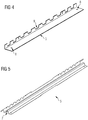
- Fig. 4 shows by way of example and schematically a conventional connection carrier.
- An oblique view of a connection carrier 3 is shown as it is shown, for example, in a FIG Fig. 2 application shown can be used.
- the connection carrier 3 has an essentially L-shaped cross section, one section being equipped with recesses 9. Furthermore, the connection carrier 3 comprises two water drainage bores 8.
- Fig. 5 shows an example and schematically a connection beam.
- An oblique view of a connection carrier 5 according to the invention is shown as it is, for example, in a FIG Fig. 3 application shown can be used.
- the connection carrier 5 has an essentially L-shaped cross section, one section being equipped with recesses 9.
- the second section of the connecting beam 5 is designed with a trapezoidal bead 7.
Description
Die Erfindung betrifft einen Wagenkasten für ein Passagierschienenfahrzeug.The invention relates to a car body for a passenger rail vehicle.
Ein solches Passagierschienenfahrzeug ist z.B. aus der
Schienenfahrzeuge, insbesondere Passagierfahrzeuge werden heute meistens als selbsttragende Metallkonstruktionen hergestellt. Dabei wird ein Fahrzeugkasten aus einem Untergestell, Stirnwänden und einem Dach aufgebaut. Das Untergestell muss den Betriebskräften, besonders den Beladungs- Kupplungsdruck- und Zugkräften standhalten. Dazu wird das Untergestell häufig als Rahmenkonstruktion ausgeführt und umfasst üblicherweise zwei außenliegende Längsträger und ggf. einen Mittellangträger sowie mehrere die Längsträger verbindende Querträger und ist an den Fahrzeugenden verstärkt. Diese Verstärkung erfolgt mittels sogenannter Endstücke am Fahrzeugende und Hauptquerträgern, welche auch die Lagerungen der Drehgestelle (bzw. Einzelachsen) umfassen. Zur Zulassung von Schienenfahrzeugen ist es erforderlich bestimmte, oft für jedes Land unterschiedliche Normen zu erfüllen. Diese Normen fordern unter anderem den Nachweis, dass das Schienenfahrzeug einer bestimmten Längskraft (Kupplungsdruck) beschädigungsfrei widerstehen kann. Die für Europa gültige Norm UIC-566 fordert einen nachzuweisenden Kupplungsdruck von 2000kN, die für die USA gültige Norm fordert 3560kN. Bei diesen Kräften, welche weit oberhalb der im Betrieb auftretenden Längsdruckkräfte liegen kommt es zu elastischen Verformungen des Wagenkastens. Diese Verformungen bewirken Spannungsspitzen in verschiedenen Bauteilen, sodass eine genaue Auslegung der Konstruktion darauf Rücksicht nehmen muß. Diese Spannungsspitzen können insbesondere an Bauteilen am Übergang zwischen dem Vorbau und dem Untergestell zum Versagen von Schweißnähten, bzw. zum Bruch der betreffenden Bauteils führen. Es ist möglich, diese Bauteile mit einer wesentlich dickeren Wandstärke auszuführen, was jedoch das Fahrzeuggewicht erhöht.Rail vehicles, in particular passenger vehicles, are mostly produced today as self-supporting metal structures. A vehicle body is built up from an underframe, end walls and a roof. The underframe must withstand the operating forces, especially the loading, clutch pressure and tensile forces. For this purpose, the underframe is often designed as a frame construction and usually comprises two external longitudinal members and possibly a central longitudinal member as well as several cross members connecting the longitudinal members and is reinforced at the ends of the vehicle. This reinforcement takes place by means of so-called end pieces at the vehicle end and main cross members, which also include the bearings of the bogies (or individual axles). For the approval of rail vehicles it is necessary to meet certain standards, often different for each country. Among other things, these standards require proof that the rail vehicle can withstand a certain longitudinal force (clutch pressure) without damage. The UIC-566 standard, which is valid for Europe, requires a clutch pressure of 2000kN to be verified, which is required for the USA valid standard requires 3560kN. With these forces, which are far above the longitudinal compressive forces occurring during operation, elastic deformations of the car body occur. These deformations cause stress peaks in various components, so that an exact design of the construction must take this into account. These stress peaks can lead to failure of welds or to breakage of the relevant component, particularly on components at the transition between the front end and the subframe. It is possible to design these components with a significantly thicker wall, but this increases the weight of the vehicle.
Der Erfindung liegt daher die Aufgabe zugrunde, einen Wagenkasten für ein Passagierschienenfahrzeug anzugeben, welcher auch bei hohen Axialdruckkräften nur geringe Spannungsspitzen an Bauteilen des Untergestells, insbesondere am Übergang zwischen dem Fahrzeugboden in den Vorbau aufweist.The invention is therefore based on the object of specifying a car body for a passenger rail vehicle which, even with high axial pressure forces, only has low stress peaks on components of the underframe, in particular at the transition between the vehicle floor and the front end.
Die Aufgabe wird durch einen Wagenkasten für ein Passagierschienenfahrzeug mit den Merkmalen des Anspruchs 1 gelöst. Vorteilhafte Ausgestaltungen sind Gegenstand untergeordneter Ansprüche.The object is achieved by a car body for a passenger rail vehicle with the features of claim 1. Advantageous configurations are the subject of subordinate claims.
Dem Grundgedanken der Erfindung nach ist ein Wagenkasten für ein Passagierschienenfahrzeug, umfassend ein Untergestell mit je einem Vorbau an jedem Fahrzeugende, wobei das Untergestell zwei außenliegende Längsträger umfasst, zwischen welchen ein Fahrzeugboden angeordnet ist, wobei der Fahrzeugboden aus im Querschnitt trapezähnlich gekantetem Profilblech, wobei die Sicken des Profilblechs sich in Längsrichtung des Wagenkastens erstrecken aufgebaut, wobei der Fahrzeugboden an den Übergangstellen zu je einem der Vorbauten mittels eines quer zur Längsrichtung des Wagenkastens orientierten Verbindungsträger an dem jeweiligen Vorbau fest verbunden ist und wobei der Verbindungsträger als Profilblech mit im Wesentlichen L-förmigen Querschnitt ausgeführt ist, und wobei der mit einem Vorbau verbundene Abschnitt des Verbindungsträgers mit einer trapezähnlichen Sicke ausgestattet ist.The basic idea of the invention is a car body for a passenger rail vehicle, comprising an underframe with a front end at each end of the vehicle, the underframe comprising two external longitudinal members, between which a vehicle floor is arranged, the vehicle floor being made of profiled sheet metal with a trapezoidal cross-section, with the The corrugation of the profile sheet extends in the longitudinal direction of the Car body extend constructed, the vehicle floor being firmly connected to the respective front structure at the transition points to one of the front structures by means of a connecting beam oriented transversely to the longitudinal direction of the car body, and the connecting beam being designed as a profiled sheet with a substantially L-shaped cross-section, and where the with a stem connected section of the connecting beam is equipped with a trapezoidal bead.
Dadurch ist der Vorteil erzielbar, einen Anschluß eines Fahrzeugbodens zu einem Vorbau herstellen zu können, welcher auch bei sehr hohen Längsdruckkräften die Spannungsspitzen an den Befestigungsstellen zu dem Vorbau auf wesentlich geringere Werte reduziert als es mit Lösungen aus dem Stand der Technik möglich ist.This has the advantage of being able to connect a vehicle floor to a front end which, even with very high longitudinal compressive forces, reduces the stress peaks at the attachment points to the front end to significantly lower values than is possible with solutions from the prior art.
Längsdruckkräfte, die über die Mittelpufferkupplungen auf einen Wagenkasten einwirken bedingen eine Verformung des Wagenkastens. Dabei wird der sehr massiv ausgeführte Endbereich (Vorbau) wesentlich weniger stark verformt als der im Verhältnis weicher ausgeführte Mittelbereich des Wagenkastens. Der Übergang zwischen dem gering verformten Endbereich und dem verformten Mittelbereich eines Wagenkastens ist besonders kritisch, da an dieser Stelle die höchsten Spannungsspitzen entstehen.
Wagenkästen von Schienenfahrzeugen sind häufig mit einem Fahrzeugboden aus Trapezblech gefertigt auf welchen ein Passagierraumboden aufgebracht wird. In den durch die Trapezform entstehenden Hohlräumen kann sich durch Kondensation Wasser bilden, welches abzuführen ist. Diese Wasserabführung muß durch möglichst kleine Öffnungen erfolgen, da sonst die Druckdichtheitseigenschaften kompromittiert werden. Es ist daher üblich, den Fahrzeugboden (das Trapezblech) mit einem Verbindungsträger abzuschließen und mit dem Vorbau zu verbinden, sowie eine oder mehrere Wasserablauföffnungen an dem Verbindungsträger vorzusehen. Der Verbindungsträger ist im Wesentlichen mit L-förmigem Querschnitt ausgeführt und wird mittels Schweißverbindungen an dem Fahrzeugboden und dem Vorbau befestigt.Longitudinal compressive forces that act on a car body via the central buffer couplings cause the car body to deform. The very solid end area (front end) is much less deformed than the relatively softer middle area of the car body. The transition between the slightly deformed end area and the deformed central area of a car body is particularly critical, since this is where the highest stress peaks occur.
Car bodies of rail vehicles are often made with a vehicle floor made of trapezoidal sheet metal on which a passenger compartment floor is applied. In the cavities created by the trapezoidal shape, water can form due to condensation, which has to be removed. This water drainage must take place through the smallest possible openings, otherwise the pressure-tight properties be compromised. It is therefore customary to close the vehicle floor (the trapezoidal sheet metal) with a connecting beam and to connect it to the front end, and to provide one or more water drainage openings on the connecting beam. The connecting beam is essentially designed with an L-shaped cross section and is attached to the vehicle floor and the front end by means of welded connections.
Diese Schweißverbindungen, insbesondere die Schweißverbindung zu dem Vorbau ist bei Verformung des Wagenkastens besonders hohen Zwangskräften unterworfen, sodass ihre Haltbarkeit gefährdet sein kann.These welded connections, in particular the welded connection to the front end, are subject to particularly high constraining forces when the car body is deformed, so that their durability can be endangered.
Erfindungsgemäß ist deshalb ein Verbindungsträger vorgesehen, welcher eine höhere Elastizität aufweist, sodass die Zwangskräfte durch die Verformung des Wagenkastens deutlich reduziert sind. Solcherart können sowohl die Hauptabmessungen, als auch die Wandstärken und Materialien des Verbindungsträgers beibehalten werden.According to the invention, a connection beam is therefore provided which has a higher elasticity, so that the constraining forces due to the deformation of the car body are significantly reduced. In this way, both the main dimensions and the wall thicknesses and materials of the connecting beam can be retained.
Der Verbindungsträger ist an der dem Vorbau zugewandten Seite, dem entsprechenden Schenkel des L-förmigen Querschnitts mit einem die Elastizität erhöhendem Merkmal ausgestattet. Dabei wird dieser Abschnitt mit einer trapezähnlichen Sicke ausgeführt, sodass das Widerstandsmoment des Verbindungsträgers stark reduziert ist.On the side facing the front end, the corresponding leg of the L-shaped cross-section, the connecting beam is equipped with a feature that increases the elasticity. This section is designed with a trapezoidal bead, so that the moment of resistance of the connecting beam is greatly reduced.
Erfindungsgemäß ist der Verbindungsträger mit Ausnehmungen ausgestattet, durch welche ein Abschnitt des Fahrzeugbodens durchführbar ist. Dadurch kann eine besonders feste Verbindung mit dem Fahrzeugboden herstellt werden da die Länge der den Verbindungsträger mit dem Fahrzeugboden verbindende Schweißnaht erhöht wird.According to the invention, the connecting support is equipped with recesses through which a section of the vehicle floor can be passed. In this way, a particularly firm connection to the vehicle floor can be established, since the length of the weld seam connecting the connection beam to the vehicle floor is increased.
Es ist vorteilhaft, den Verbindungsträger mit mindestens einer Wasserablaufbohrung auszustatten, sodass das in den Hohlräumen des Fahrzeugbodens gesammelte Wasser abfließen kann.It is advantageous to equip the connection carrier with at least one water drainage hole, so that in the Water collected in cavities in the vehicle floor can drain away.
Ein erfindungsgemäßer Wagenkasten kann auf zwei Arten hergestellt werden. Gemäß einer Ausführungsform kann der Verbindungsträger aus mehreren untereinander verschweißten einzelnen Blechen aufgebaut werden.
Eine zweite Ausführungsform sieht die Herstellung des Verbindungsträgers mittels eines Umformverfahrens aus einem einzelnen Blech (einstückig) vor.A car body according to the invention can be manufactured in two ways. According to one embodiment, the connection carrier can be constructed from a plurality of individual metal sheets that are welded to one another.
A second embodiment provides for the connection carrier to be produced from a single sheet metal (in one piece) by means of a forming process.
Es zeigen beispielhaft:
-
Fig.1 Fahrzeugboden Querschnitt. -
Fig.2 Fahrzeugboden, Übergang zu einem Vorbau mit einem herkömmlichen Verbindungsträger. -
Fig.3 Fahrzeugboden, Übergang zu einem Vorbau mit einem Verbindungsträger. -
Fig.4 Herkömmlicher Verbindungsträger. -
Fig.5 Verbindungsträger.
-
Fig. 1 Vehicle floor cross section. -
Fig. 2 Vehicle floor, transition to a front end with a conventional connecting beam. -
Fig. 3 Vehicle floor, transition to a front end with a connecting beam. -
Fig. 4 Conventional connection beam. -
Fig. 5 Connecting beam.
Verbindungsträger. Es ist die Übergangsstelle aus
- 11
- LängsträgerSide member
- 22
- FahrzeugbodenVehicle floor
- 33
- Verbindungsträger altConnection carrier old
- 44th
- VorbauStem
- 55
- VerbindungsträgerConnecting beam
- 66th
- SchweißnahtWeld
- 77th
- SickeBead
- 88th
- WasserablaufbohrungWater drainage hole
- 99
- AusnehmungRecess
Claims (4)
- Car body for a passenger rail vehicle, comprising a chassis with a front assembly (4) at each vehicle end, wherein the chassis comprises two outer-lying longitudinal beams (1), between which a vehicle floor (2) is arranged, wherein the vehicle floor (2) is configured from a profiled metal sheet edged in a trapezoid-like manner in the cross-section, wherein the beads of the profiled metal sheet extend in the longitudinal direction of the car body, and wherein
the vehicle floor (2) is fixedly connected to each front assembly (4) at the transition points to said front assembly (4) by means of a connecting beam (5) oriented transversely to the longitudinal direction of the car body and wherein the connecting beam (5) is designed as a profiled metal sheet having a substantially L-shaped cross-section, characterised in that the section of the connecting beam (5) connected to a front assembly (4) is equipped with a trapezoid-like bead (7) and wherein the connecting beam (5) has cut-outs (9), through which a section of the vehicle floor (2) is passed. - Car body for a passenger rail vehicle according to one of claims 1 or 2,
characterised in that the connecting beam (5) has at least one water outlet borehole (8). - Car body for a passenger rail vehicle according to one of claims 1 to 3,
characterised in that the connecting beam (5) is assembled from a number of individual metal sheets welded together. - Car body for a passenger rail vehicle according to one of claims 1 to 3,
characterised in that the connecting beam (5) is produced in one piece from an individual metal sheet by means of a deformation method.
Priority Applications (1)
| Application Number | Priority Date | Filing Date | Title |
|---|---|---|---|
| PL17705137T PL3374245T3 (en) | 2016-02-17 | 2017-02-15 | Car body for a passenger rail vehicle |
Applications Claiming Priority (2)
| Application Number | Priority Date | Filing Date | Title |
|---|---|---|---|
| ATA50105/2016A AT518382B1 (en) | 2016-02-17 | 2016-02-17 | Car body for a passenger rail vehicle |
| PCT/EP2017/053384 WO2017140717A1 (en) | 2016-02-17 | 2017-02-15 | Car body for a passenger rail vehicle |
Publications (2)
| Publication Number | Publication Date |
|---|---|
| EP3374245A1 EP3374245A1 (en) | 2018-09-19 |
| EP3374245B1 true EP3374245B1 (en) | 2021-05-12 |
Family
ID=58044087
Family Applications (1)
| Application Number | Title | Priority Date | Filing Date |
|---|---|---|---|
| EP17705137.2A Active EP3374245B1 (en) | 2016-02-17 | 2017-02-15 | Car body for a passenger rail vehicle |
Country Status (6)
| Country | Link |
|---|---|
| US (1) | US10906563B2 (en) |
| EP (1) | EP3374245B1 (en) |
| CN (1) | CN108602520B (en) |
| AT (1) | AT518382B1 (en) |
| PL (1) | PL3374245T3 (en) |
| WO (1) | WO2017140717A1 (en) |
Family Cites Families (12)
| Publication number | Priority date | Publication date | Assignee | Title |
|---|---|---|---|---|
| DE4008703A1 (en) * | 1990-03-17 | 1991-09-19 | Audi Ag | Support structure for road vehicle - comprises bearer with plate attached via welded flange |
| JPH05254429A (en) * | 1992-03-13 | 1993-10-05 | Tokyu Car Corp | Underframe for railway vehicle |
| FR2691937B1 (en) * | 1992-06-03 | 1994-07-22 | Alsthom Gec | RAILWAY VEHICLE BODY IN STAINLESS STEEL. |
| JP3562795B2 (en) * | 2000-08-29 | 2004-09-08 | 川崎重工業株式会社 | Body frame of railway vehicle with double side beams |
| CN201516856U (en) * | 2009-10-16 | 2010-06-30 | 青岛四方庞巴迪铁路运输设备有限公司 | Railway carriage underframe end portion structure |
| CN201580395U (en) * | 2009-10-30 | 2010-09-15 | 青岛四方庞巴迪铁路运输设备有限公司 | Stainless steel vehicle body chassis structure of railway vehicle |
| AT511290A1 (en) * | 2011-04-04 | 2012-10-15 | Siemens Ag Oesterreich | RAIL VEHICLE WITH DEFORMATION ZONE |
| AT511291A1 (en) * | 2011-04-04 | 2012-10-15 | Siemens Ag Oesterreich | RAIL VEHICLE WITH PLACED FORGING ZONE |
| JP5931548B2 (en) * | 2012-04-02 | 2016-06-08 | 川崎重工業株式会社 | Railway vehicle |
| CN104354711A (en) * | 2014-11-12 | 2015-02-18 | 南车二七车辆有限公司 | Splicing center sill for railway wagon |
| CN204956497U (en) * | 2015-08-11 | 2016-01-13 | 南车眉山车辆有限公司 | Railway freight car fish belly sill chassis |
| JP6647907B2 (en) * | 2016-02-18 | 2020-02-14 | 日本車輌製造株式会社 | Railcar structure |
-
2016
- 2016-02-17 AT ATA50105/2016A patent/AT518382B1/en not_active IP Right Cessation
-
2017
- 2017-02-15 US US15/999,272 patent/US10906563B2/en active Active
- 2017-02-15 WO PCT/EP2017/053384 patent/WO2017140717A1/en active Application Filing
- 2017-02-15 PL PL17705137T patent/PL3374245T3/en unknown
- 2017-02-15 EP EP17705137.2A patent/EP3374245B1/en active Active
- 2017-02-15 CN CN201780012085.7A patent/CN108602520B/en active Active
Non-Patent Citations (1)
| Title |
|---|
| None * |
Also Published As
| Publication number | Publication date |
|---|---|
| WO2017140717A1 (en) | 2017-08-24 |
| CN108602520A (en) | 2018-09-28 |
| US10906563B2 (en) | 2021-02-02 |
| US20190106129A1 (en) | 2019-04-11 |
| PL3374245T3 (en) | 2021-11-02 |
| AT518382A1 (en) | 2017-09-15 |
| AT518382B1 (en) | 2017-12-15 |
| CN108602520B (en) | 2021-02-09 |
| EP3374245A1 (en) | 2018-09-19 |
Similar Documents
| Publication | Publication Date | Title |
|---|---|---|
| DE102010014302A1 (en) | Aircraft and mounting arrangement for a floor structure in an aircraft | |
| DE102008057196A1 (en) | Axle carrier i.e. rear axle carrier, for car, has side parts connected with each other by two cross bridges at frame construction, where one of cross bridges includes two individual profiles formed separately from each other | |
| DE102009026458A1 (en) | Structural component and manufacturing method for a structural component | |
| DE102008008246A1 (en) | Bushing bearing with reduced space requirement | |
| DE102005003978A1 (en) | Body component of motor vehicle has reinforcing profile of high strength material fixed on body profile and with geometrical dimensions matching those of latter at least in opposite sections | |
| DE102013010332A1 (en) | Sandwich component for body e.g. floor structure of motor car, has amplification profile arranged within component at side edge of component such that top face and underside of profile are covered by fiber reinforced plastic covering layers | |
| WO2011134788A1 (en) | Reinforced longitudinal beam for a railway vehicle | |
| DE102019109554A1 (en) | Spiral spring element made from a fiber plastic composite material | |
| DE102012207901A1 (en) | Vehicle body has adapter mounted at component in connection area, which is connected to another component for forming node, where adapter is made of more ductile material than former component that is made of fiber reinforced plastic | |
| DE102008024585A1 (en) | Spring element for e.g. spring shock absorber, of motor vehicle, has spring bands formed in wave like structure with respect to imaginary surface, which is fixed by spring centre lines | |
| WO2011038751A1 (en) | Longitudinal girder for rail vehicles | |
| DE102011115855A1 (en) | Structure component e.g. elongated open-or closed-fiber-reinforced plastic profile part for front wagon of motor car, has open metal profile part whose face surfaces are aligned with attachment surfaces of plastic profile part | |
| DE102015008261A1 (en) | Impact beam, side door and vehicle | |
| DE102013222016A1 (en) | Method for producing a reinforced fiber composite component in shell construction | |
| EP3798080A1 (en) | Support structure module for a wagon | |
| DE102010027354A1 (en) | Supporting structure for vehicle body, has two longitudinal support units, where latter longitudinal support unit is coupled to coupling unit | |
| DE102013215323A1 (en) | Fastening element for a body part and fastening system with fastening element | |
| EP3374245B1 (en) | Car body for a passenger rail vehicle | |
| DE102013010325A1 (en) | Reinforcement element for a motor vehicle door, motor vehicle door and method for producing a reinforcing element | |
| DE102012001054A1 (en) | Kickstay for a chassis | |
| DE102015225760A1 (en) | Carrier element, motor vehicle with a carrier element and method for producing a carrier element | |
| DE102017003024A1 (en) | End element for introducing force into a prefabricated fiber-reinforced plastic composite pipe | |
| DE102011113742A1 (en) | Carrier e.g. angle profile, for use in commercial vehicle, has sandwich structure connected with plastic layer, where layer is connected with upper and lower belts such that shear panel is formed in plastic layer during loading of carrier | |
| DE102013222970A1 (en) | Method for connecting two components, connecting portion of a component and composite component | |
| DE102013113552A1 (en) | Carrier part for a car body in shell construction |
Legal Events
| Date | Code | Title | Description |
|---|---|---|---|
| STAA | Information on the status of an ep patent application or granted ep patent |
Free format text: STATUS: UNKNOWN |
|
| STAA | Information on the status of an ep patent application or granted ep patent |
Free format text: STATUS: THE INTERNATIONAL PUBLICATION HAS BEEN MADE |
|
| PUAI | Public reference made under article 153(3) epc to a published international application that has entered the european phase |
Free format text: ORIGINAL CODE: 0009012 |
|
| STAA | Information on the status of an ep patent application or granted ep patent |
Free format text: STATUS: REQUEST FOR EXAMINATION WAS MADE |
|
| 17P | Request for examination filed |
Effective date: 20180615 |
|
| AK | Designated contracting states |
Kind code of ref document: A1 Designated state(s): AL AT BE BG CH CY CZ DE DK EE ES FI FR GB GR HR HU IE IS IT LI LT LU LV MC MK MT NL NO PL PT RO RS SE SI SK SM TR |
|
| AX | Request for extension of the european patent |
Extension state: BA ME |
|
| DAV | Request for validation of the european patent (deleted) | ||
| DAX | Request for extension of the european patent (deleted) | ||
| RAP1 | Party data changed (applicant data changed or rights of an application transferred) |
Owner name: SIEMENS MOBILITY GMBH |
|
| RAP1 | Party data changed (applicant data changed or rights of an application transferred) |
Owner name: SIEMENS MOBILITY AUSTRIA GMBH |
|
| GRAP | Despatch of communication of intention to grant a patent |
Free format text: ORIGINAL CODE: EPIDOSNIGR1 |
|
| STAA | Information on the status of an ep patent application or granted ep patent |
Free format text: STATUS: GRANT OF PATENT IS INTENDED |
|
| INTG | Intention to grant announced |
Effective date: 20201218 |
|
| GRAS | Grant fee paid |
Free format text: ORIGINAL CODE: EPIDOSNIGR3 |
|
| GRAA | (expected) grant |
Free format text: ORIGINAL CODE: 0009210 |
|
| STAA | Information on the status of an ep patent application or granted ep patent |
Free format text: STATUS: THE PATENT HAS BEEN GRANTED |
|
| AK | Designated contracting states |
Kind code of ref document: B1 Designated state(s): AL AT BE BG CH CY CZ DE DK EE ES FI FR GB GR HR HU IE IS IT LI LT LU LV MC MK MT NL NO PL PT RO RS SE SI SK SM TR |
|
| REG | Reference to a national code |
Ref country code: GB Ref legal event code: FG4D Free format text: NOT ENGLISH |
|
| REG | Reference to a national code |
Ref country code: CH Ref legal event code: EP |
|
| REG | Reference to a national code |
Ref country code: DE Ref legal event code: R096 Ref document number: 502017010336 Country of ref document: DE |
|
| REG | Reference to a national code |
Ref country code: IE Ref legal event code: FG4D Free format text: LANGUAGE OF EP DOCUMENT: GERMAN |
|
| REG | Reference to a national code |
Ref country code: AT Ref legal event code: REF Ref document number: 1392012 Country of ref document: AT Kind code of ref document: T Effective date: 20210615 |
|
| REG | Reference to a national code |
Ref country code: LT Ref legal event code: MG9D |
|
| REG | Reference to a national code |
Ref country code: NL Ref legal event code: MP Effective date: 20210512 |
|
| PG25 | Lapsed in a contracting state [announced via postgrant information from national office to epo] |
Ref country code: FI Free format text: LAPSE BECAUSE OF FAILURE TO SUBMIT A TRANSLATION OF THE DESCRIPTION OR TO PAY THE FEE WITHIN THE PRESCRIBED TIME-LIMIT Effective date: 20210512 Ref country code: LT Free format text: LAPSE BECAUSE OF FAILURE TO SUBMIT A TRANSLATION OF THE DESCRIPTION OR TO PAY THE FEE WITHIN THE PRESCRIBED TIME-LIMIT Effective date: 20210512 Ref country code: HR Free format text: LAPSE BECAUSE OF FAILURE TO SUBMIT A TRANSLATION OF THE DESCRIPTION OR TO PAY THE FEE WITHIN THE PRESCRIBED TIME-LIMIT Effective date: 20210512 Ref country code: BG Free format text: LAPSE BECAUSE OF FAILURE TO SUBMIT A TRANSLATION OF THE DESCRIPTION OR TO PAY THE FEE WITHIN THE PRESCRIBED TIME-LIMIT Effective date: 20210812 |
|
| PG25 | Lapsed in a contracting state [announced via postgrant information from national office to epo] |
Ref country code: GR Free format text: LAPSE BECAUSE OF FAILURE TO SUBMIT A TRANSLATION OF THE DESCRIPTION OR TO PAY THE FEE WITHIN THE PRESCRIBED TIME-LIMIT Effective date: 20210813 Ref country code: IS Free format text: LAPSE BECAUSE OF FAILURE TO SUBMIT A TRANSLATION OF THE DESCRIPTION OR TO PAY THE FEE WITHIN THE PRESCRIBED TIME-LIMIT Effective date: 20210912 Ref country code: LV Free format text: LAPSE BECAUSE OF FAILURE TO SUBMIT A TRANSLATION OF THE DESCRIPTION OR TO PAY THE FEE WITHIN THE PRESCRIBED TIME-LIMIT Effective date: 20210512 Ref country code: PT Free format text: LAPSE BECAUSE OF FAILURE TO SUBMIT A TRANSLATION OF THE DESCRIPTION OR TO PAY THE FEE WITHIN THE PRESCRIBED TIME-LIMIT Effective date: 20210913 Ref country code: NO Free format text: LAPSE BECAUSE OF FAILURE TO SUBMIT A TRANSLATION OF THE DESCRIPTION OR TO PAY THE FEE WITHIN THE PRESCRIBED TIME-LIMIT Effective date: 20210812 Ref country code: RS Free format text: LAPSE BECAUSE OF FAILURE TO SUBMIT A TRANSLATION OF THE DESCRIPTION OR TO PAY THE FEE WITHIN THE PRESCRIBED TIME-LIMIT Effective date: 20210512 Ref country code: SE Free format text: LAPSE BECAUSE OF FAILURE TO SUBMIT A TRANSLATION OF THE DESCRIPTION OR TO PAY THE FEE WITHIN THE PRESCRIBED TIME-LIMIT Effective date: 20210512 |
|
| PG25 | Lapsed in a contracting state [announced via postgrant information from national office to epo] |
Ref country code: NL Free format text: LAPSE BECAUSE OF FAILURE TO SUBMIT A TRANSLATION OF THE DESCRIPTION OR TO PAY THE FEE WITHIN THE PRESCRIBED TIME-LIMIT Effective date: 20210512 |
|
| PG25 | Lapsed in a contracting state [announced via postgrant information from national office to epo] |
Ref country code: ES Free format text: LAPSE BECAUSE OF FAILURE TO SUBMIT A TRANSLATION OF THE DESCRIPTION OR TO PAY THE FEE WITHIN THE PRESCRIBED TIME-LIMIT Effective date: 20210512 Ref country code: RO Free format text: LAPSE BECAUSE OF FAILURE TO SUBMIT A TRANSLATION OF THE DESCRIPTION OR TO PAY THE FEE WITHIN THE PRESCRIBED TIME-LIMIT Effective date: 20210512 Ref country code: EE Free format text: LAPSE BECAUSE OF FAILURE TO SUBMIT A TRANSLATION OF THE DESCRIPTION OR TO PAY THE FEE WITHIN THE PRESCRIBED TIME-LIMIT Effective date: 20210512 Ref country code: DK Free format text: LAPSE BECAUSE OF FAILURE TO SUBMIT A TRANSLATION OF THE DESCRIPTION OR TO PAY THE FEE WITHIN THE PRESCRIBED TIME-LIMIT Effective date: 20210512 Ref country code: SK Free format text: LAPSE BECAUSE OF FAILURE TO SUBMIT A TRANSLATION OF THE DESCRIPTION OR TO PAY THE FEE WITHIN THE PRESCRIBED TIME-LIMIT Effective date: 20210512 Ref country code: SM Free format text: LAPSE BECAUSE OF FAILURE TO SUBMIT A TRANSLATION OF THE DESCRIPTION OR TO PAY THE FEE WITHIN THE PRESCRIBED TIME-LIMIT Effective date: 20210512 |
|
| REG | Reference to a national code |
Ref country code: DE Ref legal event code: R097 Ref document number: 502017010336 Country of ref document: DE |
|
| PLBE | No opposition filed within time limit |
Free format text: ORIGINAL CODE: 0009261 |
|
| STAA | Information on the status of an ep patent application or granted ep patent |
Free format text: STATUS: NO OPPOSITION FILED WITHIN TIME LIMIT |
|
| 26N | No opposition filed |
Effective date: 20220215 |
|
| PG25 | Lapsed in a contracting state [announced via postgrant information from national office to epo] |
Ref country code: IS Free format text: LAPSE BECAUSE OF FAILURE TO SUBMIT A TRANSLATION OF THE DESCRIPTION OR TO PAY THE FEE WITHIN THE PRESCRIBED TIME-LIMIT Effective date: 20210912 Ref country code: AL Free format text: LAPSE BECAUSE OF FAILURE TO SUBMIT A TRANSLATION OF THE DESCRIPTION OR TO PAY THE FEE WITHIN THE PRESCRIBED TIME-LIMIT Effective date: 20210512 |
|
| PG25 | Lapsed in a contracting state [announced via postgrant information from national office to epo] |
Ref country code: IT Free format text: LAPSE BECAUSE OF FAILURE TO SUBMIT A TRANSLATION OF THE DESCRIPTION OR TO PAY THE FEE WITHIN THE PRESCRIBED TIME-LIMIT Effective date: 20210512 |
|
| PG25 | Lapsed in a contracting state [announced via postgrant information from national office to epo] |
Ref country code: MC Free format text: LAPSE BECAUSE OF FAILURE TO SUBMIT A TRANSLATION OF THE DESCRIPTION OR TO PAY THE FEE WITHIN THE PRESCRIBED TIME-LIMIT Effective date: 20210512 |
|
| REG | Reference to a national code |
Ref country code: BE Ref legal event code: MM Effective date: 20220228 |
|
| PG25 | Lapsed in a contracting state [announced via postgrant information from national office to epo] |
Ref country code: LU Free format text: LAPSE BECAUSE OF NON-PAYMENT OF DUE FEES Effective date: 20220215 |
|
| PG25 | Lapsed in a contracting state [announced via postgrant information from national office to epo] |
Ref country code: IE Free format text: LAPSE BECAUSE OF NON-PAYMENT OF DUE FEES Effective date: 20220215 |
|
| PG25 | Lapsed in a contracting state [announced via postgrant information from national office to epo] |
Ref country code: BE Free format text: LAPSE BECAUSE OF NON-PAYMENT OF DUE FEES Effective date: 20220228 |
|
| PGFP | Annual fee paid to national office [announced via postgrant information from national office to epo] |
Ref country code: FR Payment date: 20230221 Year of fee payment: 7 Ref country code: CZ Payment date: 20230206 Year of fee payment: 7 Ref country code: AT Payment date: 20230109 Year of fee payment: 7 |
|
| PGFP | Annual fee paid to national office [announced via postgrant information from national office to epo] |
Ref country code: TR Payment date: 20230214 Year of fee payment: 7 Ref country code: PL Payment date: 20230203 Year of fee payment: 7 Ref country code: GB Payment date: 20230308 Year of fee payment: 7 Ref country code: DE Payment date: 20220620 Year of fee payment: 7 |
|
| PGFP | Annual fee paid to national office [announced via postgrant information from national office to epo] |
Ref country code: CH Payment date: 20230504 Year of fee payment: 7 |
|
| PG25 | Lapsed in a contracting state [announced via postgrant information from national office to epo] |
Ref country code: HU Free format text: LAPSE BECAUSE OF FAILURE TO SUBMIT A TRANSLATION OF THE DESCRIPTION OR TO PAY THE FEE WITHIN THE PRESCRIBED TIME-LIMIT; INVALID AB INITIO Effective date: 20170215 |