EP3372536B1 - Endlosband mit zugträger - Google Patents
Endlosband mit zugträger Download PDFInfo
- Publication number
- EP3372536B1 EP3372536B1 EP18161082.5A EP18161082A EP3372536B1 EP 3372536 B1 EP3372536 B1 EP 3372536B1 EP 18161082 A EP18161082 A EP 18161082A EP 3372536 B1 EP3372536 B1 EP 3372536B1
- Authority
- EP
- European Patent Office
- Prior art keywords
- belt
- endless
- endless belt
- fabric
- edges
- Prior art date
- Legal status (The legal status is an assumption and is not a legal conclusion. Google has not performed a legal analysis and makes no representation as to the accuracy of the status listed.)
- Active
Links
- 239000004744 fabric Substances 0.000 claims description 34
- 239000000463 material Substances 0.000 claims description 34
- 235000013305 food Nutrition 0.000 claims description 16
- 239000004760 aramid Substances 0.000 claims description 4
- 229920003235 aromatic polyamide Polymers 0.000 claims description 4
- 238000005520 cutting process Methods 0.000 claims description 3
- 238000000034 method Methods 0.000 claims description 3
- 229920000728 polyester Polymers 0.000 claims description 3
- 238000004080 punching Methods 0.000 claims description 2
- 238000004519 manufacturing process Methods 0.000 description 13
- 238000005299 abrasion Methods 0.000 description 7
- 239000000047 product Substances 0.000 description 5
- 238000009940 knitting Methods 0.000 description 4
- 239000002537 cosmetic Substances 0.000 description 3
- 239000000825 pharmaceutical preparation Substances 0.000 description 3
- 229940127557 pharmaceutical product Drugs 0.000 description 3
- 238000009941 weaving Methods 0.000 description 3
- 229920006231 aramid fiber Polymers 0.000 description 2
- 238000009954 braiding Methods 0.000 description 2
- 229920000271 Kevlar® Polymers 0.000 description 1
- 238000010276 construction Methods 0.000 description 1
- 230000001419 dependent effect Effects 0.000 description 1
- 239000000835 fiber Substances 0.000 description 1
- 239000004761 kevlar Substances 0.000 description 1
- 239000011265 semifinished product Substances 0.000 description 1
- 238000000926 separation method Methods 0.000 description 1
- 239000004753 textile Substances 0.000 description 1
- 230000003313 weakening effect Effects 0.000 description 1
- 239000002759 woven fabric Substances 0.000 description 1
Images
Classifications
-
- B—PERFORMING OPERATIONS; TRANSPORTING
- B65—CONVEYING; PACKING; STORING; HANDLING THIN OR FILAMENTARY MATERIAL
- B65G—TRANSPORT OR STORAGE DEVICES, e.g. CONVEYORS FOR LOADING OR TIPPING, SHOP CONVEYOR SYSTEMS OR PNEUMATIC TUBE CONVEYORS
- B65G15/00—Conveyors having endless load-conveying surfaces, i.e. belts and like continuous members, to which tractive effort is transmitted by means other than endless driving elements of similar configuration
- B65G15/30—Belts or like endless load-carriers
- B65G15/32—Belts or like endless load-carriers made of rubber or plastics
- B65G15/34—Belts or like endless load-carriers made of rubber or plastics with reinforcing layers, e.g. of fabric
-
- B—PERFORMING OPERATIONS; TRANSPORTING
- B29—WORKING OF PLASTICS; WORKING OF SUBSTANCES IN A PLASTIC STATE IN GENERAL
- B29D—PRODUCING PARTICULAR ARTICLES FROM PLASTICS OR FROM SUBSTANCES IN A PLASTIC STATE
- B29D29/00—Producing belts or bands
- B29D29/06—Conveyor belts
Definitions
- the invention relates to an endless belt with a carrying side, a running side and a first and a second belt edge, which run along a running direction, a tension member that is arranged between the carrying side and the running side, the tension member having a fabric that extends from the first to the second band edge extends.
- Endless belts of the type mentioned above are also referred to as belts and are used as conveyor belts for guiding and / or receiving objects.
- the term endless belt is understood here to mean a belt or a belt which is produced continuously without ends and can thus be guided and driven over rollers, for example.
- the endless belt according to the invention has a carrying side, a running side and a first and a second belt edge. The belt edges run along a running direction of the endless belt.
- the endless belt also has a tension member.
- the tension member has a fabric which is arranged between the carrying side and the running side and serves to absorb tensile forces along the running direction of the endless belt.
- the fabric of the tension member has at least two different materials in a direction perpendicular to the running direction. It is provided in particular that the fabric has a first material in a region of the belt edges and has a second material in a region facing away from the belt edges, the first material and the second material being different.
- the first material is food-safe in the area of the belt edges.
- the carrying sides and the running sides, that can come into direct or indirect contact with the food can be brought into compliance with the relevant regulations in a comparatively simple manner.
- the tension member on the other hand, which should not actually come into contact with the food, can be exposed by abrasion, for example on guide surfaces, and thus ensure undesirable product contact.
- the area near the belt edges can be particularly affected by wear.
- One possibility for solving the problem could be to create a tension member-free buffer area at the edge areas of the endless belt near the belt edges. But this is a very complex manufacturing process.
- the various boundary conditions can be taken into account significantly better.
- the material for the central area need not be food grade as it will not be exposed even with extreme abrasion. It can thus be designed with the necessary tensile strength regardless of food compatibility.
- the material in the edge area near the belt edges is designed to be food-compatible and on the one hand cannot contaminate the product if abrasion occurs.
- the edge area continues to contribute to the tensile strength of the endless belt due to the presence of a tension carrier fabric.
- fabric is intended to encompass various sheet-like textile structures with various types of production such as woven, knitted, knitted or braided fabrics, also in combination with one another.
- the tension member is designed in several parts.
- one part of the tension member can be arranged in the region of the belt edges and another part of the tension member can be arranged centrally, that is to say in the region facing away from the belt edges.
- the individual parts of the tension member can have the different materials and can be connected to one another, for example, during a manufacturing process such as knitting, weaving, warp-knitting or braiding be.
- the first material comprises a polyester. Polyester fabrics such as PES are easy to process as food-compatible tension members and have sufficient tensile strength for the edge areas.
- the second material has a tensile strength per 10 mm of endless width of at least 800 N, a belt elongation of a maximum of 2% for 10 mm of endless width at 300 N and a maximum of 2% for 600 N in the area remote from the belt edges 4%, at 1000 N of a maximum of 6% and a force at 1% elongation and 10 mm of endless width of at least 200 N.
- the specified material parameters only represent a lower limit.
- An exemplary tension member material has a tensile strength per 10 mm of endless width of at least 7000 N, a belt elongation for 10 mm of endless width at 300 N of a maximum of 0.3%, for 600 N of a maximum of 0.5%, for 1000 N of a maximum of 0, 7% and a force at 1% elongation and 10 mm of endless width of at least 1500 N.
- the second material comprises an aramid fabric.
- an aramid fabric is understood to mean a fabric with an aramid fiber.
- the strip edges can be produced by a cutting process. This enables a particularly simple manufacturing process. In this way, the endless strip can be separated from what is actually a wider semi-finished product. The separation can be done for example by means of cutting, sawing and / or punching.
- the fabric of the tension member can be produced, for example, by weaving, knitting, knitting and / or braiding.
- the term fabric is therefore not intended to be restricted to the production form of weaving, but is intended to encompass all possible types of production of flat structures using fibers.
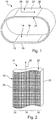
- Figure 1 shows a schematic perspective view of an endless belt 10.
- the endless belt 10 is shown elliptically in the present case. However, this only represents one possible shape in the case of use.
- the width and length ratio shown also represents only an exemplary embodiment and can be varied depending on the intended use.
- the endless belt 10 is designed in the present case for the transport of food and has a multi-layer structure.
- An inner layer 12 serves as the running side 14 in which a tension member 16 is embedded.
- the inner layer 12 forms on its inner side a running side 18 which is in contact with drive or guide rollers.
- the tension member 16 embedded in the inner layer 12 is described in detail below with reference to FIG Figure 2 are explained in more detail.
- the endless belt 10 ends with a support layer 20, which forms a support side 22.
- the support side 22 comes into direct contact with a food product to be processed.
- the carrying side 22 and the running side 18 are connected by belt edges 24, 26.
- the belt edges 24, 26 run along a running direction 28 in which the endless belt 10 is movable.
- the present invention is not limited to directional endless belts, but can of course also be used with direction-independent endless belts.
- the tension member 16 has a fabric 30, as shown in more detail in FIG Figure 2 is shown.
- a section of the endless belt 10 is shown, which is cut transversely to the running direction 28 and from which the base layer 20 has been removed.
- the tensile fabric 30 extends from one belt edge 24 to the other belt edge 26.
- the tensile fabric 30 is designed as a knitted fabric, but can also be produced as a knitted fabric, woven fabric or the like.
- the tension fabric 30 is divided into three zones which extend along the running direction 28 and adjoin one another transversely to the running or conveying direction 28.
- a central zone 34 is flanked by two lateral zones 32, 36 which are located in the area of the belt edges 24, 26.
- the central zone 34 has a different material than the lateral zones 32, 36.
- the material used in the central zone 34 is a knitted fabric made from an aramid fiber and is designed to absorb high tensile forces.
- the material can have a tear strength per 10 mm of endless width of at least 7000 N, a belt elongation for 10 mm of endless width at 300 N of a maximum of 0.3%, for 600 N of a maximum of 0.5%, for 1000 N of a maximum of 0, 7% and a force at 1% elongation and 10 mm of endless width of at least 1500 N.
- the material used in the edge zones 32, 36 has a lower tear resistance, but can instead be suitable for food, animal feed, cosmetics or pharmaceutical products. Fine abrasion or smaller detached pieces of the tension carrier fabric material do not pose a risk in the manufacture of the corresponding products.
- the weakening of the entire endless belt 10 introduced via the less tensile strength fabric material can be determined over the width of the edge zones 32, 36. The width of the edge zones 32, 36 can be adjusted depending on the expected stress on the endless belt 10 via the drive or the guide and the materials to be picked up or transported.
- the tension carrier fabric extends to the edge due to the manufacturing process, i.e. the belt edges 24, 26.
- the tension carrier fabric extends to the edge due to the manufacturing process, i.e. the belt edges 24, 26.
- the tension carrier fabric extends to the edge due to the manufacturing process, i.e. the belt edges 24, 26.
- an edge without tension carrier fabric 16 is provided between the lateral end of the tension carrier fabric and the actual lateral edge of the endless belt 10, i.e. the band edges 24, 26.
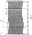
- Figure 3 shows a preliminary stage of an endless belt as it can be used in the production of an endless belt 10.
- the preliminary stage is an endless belt that is divided into several individual endless belts.
- FIG. 3 one of the Figure 2 corresponding schematic elevation of an endless belt 10 'is shown.
- the endless belt 10 'does not form an endless belt intended for use. Rather, the endless belt 10 'is separated into four individual endless belts 101-104. For this purpose, three dividing lines 40-42 are provided.
- the endless belt 10 ' like the endless belt 10, has a tension member with a tension member fabric 16'.
- a tension member fabric 16' According to the 4 endless belts 101-104 to be separated, a total of 9 different zones are provided parallel to the intended running direction 28.
- Two outer edge zones 132, 136 delimit the tensile carrier fabric 16 to the outside. They are followed by central zones 134, which alternate with intermediate zones 133.
- the outer edge zones 132, 136 and the intermediate zones 133 are made from a food-compatible fabric, the central zones 134 from a tensile strength material such as aramid or Kevlar.
Landscapes
- Engineering & Computer Science (AREA)
- Mechanical Engineering (AREA)
- Belt Conveyors (AREA)
- Woven Fabrics (AREA)
Description
- Die Erfindung betrifft ein Endlosband mit einer Tragseite, einer Laufseite sowie einer ersten und einer zweiten Bandkante, welche entlang einer Laufrichtung verlaufen, einem Zugträger, der zwischen Tragseite und Laufseite angeordnet ist, wobei der Zugträger ein Gewebe aufweist, das sich von der ersten zu der zweiten Bandkante erstreckt.
- Endlosbänder der eingangs genannten Art werden auch als Riemen bezeichnet und als Transportbänder zur Führung oder/und Aufnahme von Gegenständen eingesetzt. Unter dem Begriff Endlosband wird hier ein Band oder ein Riemen verstanden, das ohne Enden durchgehend hergestellt ist und so beispielsweise über Rollen geführt und angetrieben werden kann.
- Im Bereich der Nahrungsmittel- oder Futtermittelverarbeitung finden diese Endlosbänder im Zuge der Automatisierung der Verarbeitung zunehmend Verbreitung. Bei der Konstruktion und dem Betrieb von Anlagen, die bei der Nahrungsmittel- oder Futtermittelverarbeitung / -herstellung oder für kosmetische oder pharmazeutische Erzeugnisse eingesetzt werden, müssen besondere Vorschriften eingehalten werden, die im Folgenden mit dem Begriff "nahrungsmittelverträglich" subsumiert sein sollen.
- So kann beispielsweise bei Transportbändern, die direkt mit Nahrungsmitteln in Kontakt kommen, ein nicht vorhersehbarer Produktkontakt stattfinden. Ein solcher Produktkontakt kann beispielsweise durch sich lösenden Abrieb hervorgerufen werden. Dieser Abrieb kann in das Lebensmittel gelangen und dieses so kontaminieren. Je nach Einsatzgebiet des Endlosbandes muss es für hohe Zugkräfte ausgelegt sein. Dabei können Zugkräfte im Bereich von mehreren zehntausend Newton auftreten. Entsprechend müssen das Material und der Aufbau des Zugträgers für die Aufnahme solcher Kräfte geeignet sein. Gleichzeitig muss die Nahrungsmittelverträglichkeit eines solchen Transportbandes gewährleistet sein.
- Ein Beispiel für ein solches Transportband, welches nicht lebensmittelverträglich ist und bei welchem die transportierten Nahrungsmittel durch sich lösenden Abrieb kontaminiert werden können, ist der
DE 84 26 836 U1 zu entnehmen. Das DokumentDE 84 26 836 U1 offenbart ein Endlosband nach dem Oberbegriff des Anspruchs 1. - Es ist eine Aufgabe der Erfindung, ein Endlosband bereitzustellen, das in einer Anlage für die Herstellung unter anderem von Nahrungsmitteln, Futtermitteln oder für die Herstellung von kosmetischen oder/und pharmazeutischen Produkten eingesetzt werden kann und gleichzeitig eine besonders hohe Zugfestigkeit aufweist.
- Diese Aufgabe wird durch ein Endlosband gemäß dem unabhängigen Anspruch gelöst. Weitere Ausgestaltungen der Erfindung sind in den abhängigen Ansprüchen angegeben. Das erfindungsgemäße Endlosband weist eine Tragseite, eine Laufseite sowie eine erste und eine zweite Bandkante auf. Die Bandkanten verlaufen entlang einer Laufrichtung des Endlosbandes.
- Das Endlosband weist ferner einen Zugträger auf. Der Zugträger weist ein Gewebe auf, das zwischen der Tragseite und der Laufseite angeordnet ist und der Aufnahme von Zugkräften entlang der Laufrichtung des Endlosbandes dient. Das Gewebe des Zugträgers weist in einer Richtung senkrecht zu der Laufrichtung zumindest zwei verschiedene Materialien auf. Dabei ist insbesondere vorgesehen, dass das Gewebe in einem Bereich der Bandkanten ein erstes Material aufweist und in einem von den Bandkanten abgewandten Bereich ein zweites Material aufweist, wobei sich das erste Material und das zweite Material unterscheiden.
- Erfindungsgemäß ist vorgesehen, dass das erste Material im Bereich der Bandkanten lebensmittelverträglich ist.
- Es hat sich herausgestellt, dass für eine ausreichende Nahrungsmittelverträglichkeit die Wahl des richtigen Zugträgergewebes entscheidend ist. Die Tragseiten und die Laufseiten, die unmittelbar oder mittelbar mit dem Nahrungsmittel in Kontakt kommen können, sind auf vergleichsweise einfache Weise in Einklang mit den entsprechenden Vorschriften bringbar. Der Zugträger hingegen, der eigentlich nicht in Kontakt mit dem Nahrungsmittel kommen sollte, kann durch Abrieb beispielsweise an Führungsoberflächen freigelegt werden und so für einen unerwünschten Produktkontakt sorgen.
- Besonders der Bereich nahe der Bandkanten kann dabei von besonderem Verschleiß betroffen sein. Eine Möglichkeit zur Lösung des Problems könnte darin bestehen, an den Randbereichen des Endlosbandes nahe den Bandkanten einen zugträgerfreien Pufferbereich zu schaffen. Dies stellt aber einen sehr aufwändigen Herstellungsprozess dar.
- Durch die erfindungsgemäße Wahl unterschiedlicher Materialien für den Randbereich nahe der Bandkanten und für den zentraleren Bereich fern der Bandkanten kann den verschiedenen Randbedingungen deutlich besser Rechnung getragen werden. Das Material für den zentraleren Bereich braucht nicht nahrungsmittelverträglich zu sein, da es selbst bei extremem Abrieb nicht freigelegt werden wird. Es kann somit mit der notwendigen Zugfestigkeit ohne Rücksichtnahme auf Nahrungsmittelverträglichkeit ausgelegt sein. Im Gegensatz dazu wird das Material im Randbereich nahe der Bandkanten nahrungsmittelverträglich ausgelegt und kann so einerseits bei einem möglicherweise stattfindenden Abrieb nicht das Produkt kontaminieren. Gleichzeitig trägt der Randbereich durch das Vorhandensein eines Zugträgergewebes nach wie vor zu der Zugfestigkeit des Endlosbandes bei.
- Hier und im Folgenden sollen mit dem Begriff "Gewebe" verschiedene flächenförmige textile Gebilde mit verschiedenen Herstellungsarten wie Gewebe, Gewirke, Gestricke oder Geflechte, auch in Kombination untereinander, umfasst sein.
- Bei einer bevorzugten Ausführungsform der Erfindung ist vorgesehen, dass der Zugträger mehrteilig ausgeführt ist. Insbesondere können je ein Teil des Zugträgers im Bereich der Bandkanten und ein weiterer Teil des Zugträgers zentral, also in dem von den Bandkanten abgewandten Bereich, angeordnet sein. Die einzelnen Teile des Zugträgers können die verschiedenen Materialien aufweisen und beispielsweise während eines Herstellungsvorgangs wie beispielsweise Stricken, Weben, Wirken oder Flechten miteinander verbunden sein. Insbesondere kann vorgesehen sein, dass das erste Material ein Polyester umfasst. Polyestergewebe wie beispielsweise PES sind als nahrungsmittelverträgliche Zugträger einfach verarbeitbar und weisen eine ausreichende Zugfestigkeit für die Randbereiche auf.
- Eine Weiterbildung der Erfindung sieht vor, dass das zweite Material in dem von den Bandkanten entfernten Bereich eine Reißfestigkeit pro 10 mm endloser Breite von mindestens 800 N, eine Banddehnung bei 10 mm endloser Breite bei 300 N von maximal 2%, bei 600 N von maximal 4%, bei 1000 N von maximal 6% und eine Kraft bei 1% Dehnung und 10 mm endloser Breite von mindestens 200 N aufweist. Die angegebenen Materialparameter stellen lediglich eine Untergrenze dar.
- Ein beispielhaftes Zugträgermaterial weist eine Reißfestigkeit pro 10 mm endloser Breite von mindestens 7000 N, eine Banddehnung bei 10 mm endloser Breite bei 300 N von maximal 0,3%, bei 600 N von maximal 0,5%, bei 1000 N von maximal 0,7% und eine Kraft bei 1% Dehnung und 10 mm endloser Breite von mindestens 1500 N auf.
- Insbesondere kann vorgesehen sein, dass das zweite Material ein Aramid-Gewebe umfasst. Unter einem Aramid-Gewebe wird vorliegend ein Gewebe mit einer Aramidfaser verstanden.
- Bei einer Ausführungsform der Erfindung ist vorgesehen, dass die Bandkanten durch einen Trennvorgang herstellbar sind. Dies ermöglicht einen besonders einfachen Herstellungsvorgang. So kann das Endlosband aus einem eigentlich breiteren Halbzeug herausgetrennt werden. Das Heraustrennen kann dabei beispielsweise mittels Schneiden, Sägen und/oder Stanzen geschehen.
- Das Gewebe des Zugträgers kann beispielsweise durch Weben, Stricken, Wirken oder/und Flechten hergestellt sein. Der Begriff Gewebe soll also vorliegend nicht auf die Herstellungsform Weben beschränkt sein, sondern soll alle möglichen Herstellungsarten von Flächengebilden mittels Fasern umfassen.
- Nachfolgend werden Ausführungsbeispiele der Erfindung anhand der Zeichnungen näher erläutert. In diesen zeigen:
- Figur 1
- eine schematisch gehaltene perspektivische Ansicht einer ersten Ausführungsform eines erfindungsgemäßen Endlosbandes;
- Figur 2
- eine schematische Aufrissansicht des Endlosbandes der
Figur 1 ; und - Figur 3
- eine Vorstufe eines Endlosbandes für die Herstellung eines Endlosbandes der
Figuren 1 und 2 . -
Figur 1 zeigt eine schematische perspektivische Ansicht eines Endlosbandes 10. Das Endlosband 10 ist vorliegend elliptisch dargestellt. Dies stellt aber lediglich eine mögliche Formgebung im Einsatzfall dar. Auch stellt das dargestellte Breiten- und Längenverhältnis lediglich eine beispielhafte Ausführungsform und kann je nach Einsatzzweck variiert werden. - Das Endlosband 10 ist vorliegend für den Transport von Nahrungsmitteln ausgelegt und weist einen mehrlagigen Aufbau auf. Eine innere Schicht 12 dient als Laufseite 14, in die eine Zugträger 16 eingebettet ist. Die innere Schicht 12 bildet auf ihrer inneren Seite eine Laufseite 18, welche in Kontakt mit Antriebs- oder Führungsrollen steht. Der in die innere Schicht 12 eingebettete Zugträger 16 wird im Detail nachstehend unter Bezugnahme auf
Figur 2 näher erläutert werden. - Nach außen schließt das Endlosband 10 mit einer Tragschicht 20 ab, die eine Tragseite 22 bildet. Die Tragseite 22 kommt in direkten Kontakt mit einem zu bearbeitenden Nahrungsmittelprodukt.
- Die Tragseite 22 und die Laufseite 18 werden durch Bandkanten 24, 26 verbunden. Die Bandkanten 24, 26 verlaufen entlang einer Laufrichtung 28, in welcher das Endlosband 10 bewegbar ist. Die vorliegende Erfindung ist nicht auf laufrichtungsgebundene Endlosbänder beschränkt, sondern kann selbstverständlich auch bei laufrichtungsunabhängigen Endlosbändern eingesetzt werden.
- Der Zugträger 16 weist ein Gewebe 30 auf, wie dies näher in
Figur 2 dargestellt ist. InFigur 2 ist ein Ausschnitt aus dem Endlosband 10 gezeigt, der quer zur Laufrichtung 28 ausgeschnitten und bei dem die Tragschicht 20 entfernt wurde. - Bei der dargestellten Ausführungsform erstreckt sich das Zuggewebe 30 von einer Bandkante 24 zu der anderen Bandkante 26. Das Zuggewebe 30 ist in der vorliegenden Ausführungsform als Gestricke ausgeführt, kann aber auch als Gewirke, Gewebe oder ähnliches hergestellt sein. Das Zuggewebe 30 ist in drei Zonen eingeteilt, die sich entlang der Laufrichtung 28 erstrecken und quer zur Lauf- oder Förderrichtung 28 aneinandergrenzen. Eine zentrale Zone 34 wird von zwei seitlichen Zonen 32, 36 flankiert, die sich im Bereich der Bandkanten 24, 26 befinden.
- Die zentrale Zone 34 weist ein anderes Material auf als die seitlichen Zonen 32, 36. Das in der zentralen Zone 34 verwendete Material ist ein Gestricke aus einer Aramidfaser und für die Aufnahme hoher Zugkräfte ausgelegt. Beispielsweise kann das Material eine Reißfestigkeit pro 10 mm endloser Breite von mindestens 7000 N, eine Banddehnung bei 10 mm endloser Breite bei 300 N von maximal 0,3%, bei 600 N von maximal 0,5%, bei 1000 N von maximal 0,7% und eine Kraft bei 1% Dehnung und 10 mm endloser Breite von mindestens 1500 N aufweisen.
- Das in den Randzonen 32, 36 verwendete Material hingegen weist eine geringere Reißfestigkeit auf, kann aber stattdessen für Nahrungsmittel, Futtermittel Kosmetika oder pharmazeutische Produkte geeignet sein. Feiner Abrieb oder kleinere herausgelöste Stücke des Zugträgergewebematerials stellen somit kein Risiko bei der Herstellung der entsprechenden Produkte dar. Gleichzeitig kann über die Breite der Randzonen 32, 36 die über das weniger zugfeste Gewebematerial eingeleitete Schwächung des gesamten Endlosbands 10 bestimmt werden. Je nach zu erwartender Beanspruchung des Endlosbands 10 über den Antrieb oder die Führung sowie die aufzunehmenden oder zu transportierenden Materialien kann die Breite der Randzonen 32, 36 eingestellt werden.
- Bei der gezeigten Ausführungsform erstreckt sich das Zugträgergewebe herstellungsbedingt bis an den Rand, d.h. die Bandkanten 24, 26. Es sind aber auch Ausführungsformen denkbar, bei denen zwischen dem seitlichen Ende des Zugträgergewebes und dem eigentlichen seitlichen Rand des Endlosbands 10, d.h. den Bandkanten 24, 26 ein Rand ohne Zugträgergewebe 16 vorgesehen ist.
-
Figur 3 zeigt eine Vorstufe eines Endlosbands, wie sie bei der Herstellung eines Endlosbands 10 verwendet werden kann. Die Vorstufe bildet ein Endlosband, das in mehrere einzelne Endlosbänder zerteilt wird. - Konkret ist in
Figur 3 ein derFigur 2 entsprechender schematischer Aufriss eines Endlosbandes 10' dargestellt. Im Unterschied zu derFigur 2 bildet das Endlosband 10' kein Endlosband, das für einen Einsatz gedacht ist. Vielmehr wird das Endlosband 10' in vier einzelne Endlosbänder 101-104 vereinzelt. Hierzu sind drei Trennlinien 40-42 vorgesehen. - Das Endlosband 10' weist wie das Endlosband 10 einen Zugträger mit einem Zugträgergewebe 16' auf. Es sind entsprechend den 4 zu vereinzelten Endlosbänder 101-104 insgesamt 9 verschiedene Zonen parallel zu der vorgesehenen Laufrichtung 28 vorgesehen. 2 äußere Randzonen 132, 136 begrenzen das Zugträgergewebe 16 nach außen. Nach ihnen schließen sich zentrale Zonen 134 an, die sich mit Zwischenzonen 133 abwechseln. Die äußeren Randzonen 132, 136 und die Zwischenzonen 133 sind aus einem nahrungsmittelverträglichen Gewebe gefertigt, die zentralen Zonen 134 aus einem zugfesten Material wie beispielsweise Aramid oder Kevlar.
Claims (9)
- Endlosband (10) mita) einer Tragseite (22), einer Laufseite (18) sowie einer ersten und einer zweiten Bandkante (24, 26), welche entlang einer Laufrichtung (28) verlaufen,b) einem Zugträger (16), der zwischen Tragseite (22) und Laufseite (18) angeordnet ist, wobei der Zugträger (16) ein Gewebe (30) aufweist, das sich von der ersten (24) zu der zweiten Bandkante (26) erstreckt, wobei das Gewebe (30) in einer Richtung senkrecht zu der Laufrichtung (28) zumindest zwei verschiedene Materialien aufweist, wobei das Gewebe (30) in einem Bereich der Bandkanten (24, 26) ein erstes Material aufweist und in einem von den Bandkanten (24, 26) abgewandten Bereich ein zweites Material aufweist, wobei sich das erste Material und das zweite Material unterscheiden,
dadurch gekennzeichnet, dassc) das erste Material im Bereich der Bandkanten (24, 26) lebensmittelverträglich ist. - Endlosband nach Anspruch 1, wobei der Zugträger (16) mehrteilig ausgeführt ist.
- Endlosband nach Anspruch 2, wobei je ein Teil des Zugträgers (16) im Bereich der Bandkanten (24, 26) und ein weiterer Teil des Zugträgers (16) zentral, also in dem von den Bandkanten abgewandten Bereich, angeordnet sind und/oder die einzelnen Teile des Zugträgers (16) das erste oder das zweite Material aufweisen.
- Endlosband nach einem der vorhergehenden Ansprüche, wobei das erste Material ein Polyester umfasst.
- Endlosband nach einem der vorhergehenden Ansprüche, wobei das zweite Material in dem von den Bandkanten (24, 26) entfernten Bereich eine Reißfestigkeit pro 10 mm endloser Breite von mindestens 800 N, eine Banddehnung bei 10 mm endloser Breite bei 300 N von maximal 2%, bei 600 N von maximal 4%, bei 1000 N von maximal 6% und eine Kraft bei 1% Dehnung und 10 mm endloser Breite von mindestens 200 N aufweist.
- Endlosband nach einem der vorhergehenden Ansprüche, wobei das zweite Material ein Aramid-Gewebe umfasst.
- Endlosband nach einem der vorhergehenden Ansprüche, wobei die Bandkanten (24, 26) durch einen Trennvorgang herstellbar sind.
- Endlosband nach Anspruch 7, wobei der Trennvorgang ein Schneiden, Sägen und/oder Stanzen umfasst.
- Endlosband nach einem der vorhergehenden Ansprüche, wobei das Gewebe (30) gewebt, gestrickt, gewirkt oder/und geflochten ist.
Priority Applications (1)
| Application Number | Priority Date | Filing Date | Title |
|---|---|---|---|
| PL18161082T PL3372536T3 (pl) | 2017-03-10 | 2018-03-09 | Taśma bez końca z elementem naciągowym |
Applications Claiming Priority (1)
| Application Number | Priority Date | Filing Date | Title |
|---|---|---|---|
| DE102017105126.0A DE102017105126A1 (de) | 2017-03-10 | 2017-03-10 | Endlosband mit Zugträger |
Publications (2)
| Publication Number | Publication Date |
|---|---|
| EP3372536A1 EP3372536A1 (de) | 2018-09-12 |
| EP3372536B1 true EP3372536B1 (de) | 2020-09-16 |
Family
ID=61626939
Family Applications (1)
| Application Number | Title | Priority Date | Filing Date |
|---|---|---|---|
| EP18161082.5A Active EP3372536B1 (de) | 2017-03-10 | 2018-03-09 | Endlosband mit zugträger |
Country Status (3)
| Country | Link |
|---|---|
| EP (1) | EP3372536B1 (de) |
| DE (1) | DE102017105126A1 (de) |
| PL (1) | PL3372536T3 (de) |
Family Cites Families (6)
| Publication number | Priority date | Publication date | Assignee | Title |
|---|---|---|---|---|
| DE1982374U (de) | 1967-02-23 | 1968-03-28 | Rost & Co H | Foerderband bzw. treibriemen. |
| DE8426836U1 (de) | 1984-09-12 | 1984-12-13 | Walraf Textilwerke GmbH & Co, 4050 Mönchengladbach | Einlage, vorzugsweise textileinlage, fuer foerderbaender |
| FR2649084A1 (fr) | 1989-07-03 | 1991-01-04 | Depreux Sa | Bande transporteuse |
| DE202004019688U1 (de) * | 2004-12-17 | 2005-03-03 | Sattler Ag | Textilband für Transport, Weiterverarbeitung und/oder Lagerung von Lebensmitteln, insbesondere Backwaren |
| CA2714955C (en) * | 2009-10-09 | 2013-12-31 | Veyance Technologies, Inc. | Conveyor belt with varying flexibility and method of construction of same |
| DE102015212480A1 (de) * | 2015-07-03 | 2017-01-05 | Contitech Transportbandsysteme Gmbh | In Längsrichtung endlos geschlossenes Band, insbesondere Rundballenpressband |
-
2017
- 2017-03-10 DE DE102017105126.0A patent/DE102017105126A1/de not_active Withdrawn
-
2018
- 2018-03-09 EP EP18161082.5A patent/EP3372536B1/de active Active
- 2018-03-09 PL PL18161082T patent/PL3372536T3/pl unknown
Non-Patent Citations (1)
| Title |
|---|
| None * |
Also Published As
| Publication number | Publication date |
|---|---|
| EP3372536A1 (de) | 2018-09-12 |
| DE102017105126A1 (de) | 2018-09-13 |
| PL3372536T3 (pl) | 2021-05-31 |
Similar Documents
| Publication | Publication Date | Title |
|---|---|---|
| EP3147239B1 (de) | Zahnriemen mit integrierten stützrollen | |
| EP3329145B1 (de) | Gurt oder gurtsegment | |
| WO2003016190A1 (de) | Verbindungsstelle von zwei garnenden | |
| EP1743966B1 (de) | Weblitze, insbesondere für schnell laufende Webmaschinen | |
| EP2674030B1 (de) | Eierband | |
| EP2907776B1 (de) | Transportvorrichtung mit einem endlosen bandförmigen Transportelement | |
| EP0999015A2 (de) | Bahnschneidvorrichtung mit einer integrierten Messeranordnung in einer Rollenrotationsdruckmaschine | |
| EP3372536B1 (de) | Endlosband mit zugträger | |
| EP2877341B1 (de) | Trenneinrichtung zum trennen von stoffen unterschiedlicher fliessfähigkeit | |
| EP1017890B1 (de) | Verfahren und vorrichtung zum vereinzeln von litzen | |
| DE7723785U1 (de) | Vorrichtung zum ausrichten von mit einem bindemittel versehenen, lignozellulosehaltigen teilchen | |
| EP3839287A1 (de) | Riemen als endloses zugmittel für förderbänder von ballenpressen oder ballenwicklern | |
| DE202011108695U1 (de) | Vorrichtung zum Schälen von mandelartigen Früchten | |
| DE2339941C3 (de) | Förderband für einen Zugseil-Gurtbandförderer | |
| EP2505702B2 (de) | Weblitze mit einem abschnittsweise aus mehreren Folienlagen gebildeten Litzenkörper | |
| DE102011113193B4 (de) | Transportband | |
| EP2584078B1 (de) | Weblitze mit fadenfreundlichem Fadenauge | |
| EP1799894B1 (de) | Führungselemente für ein greifertransportmittel einer webmaschine | |
| WO2020141006A1 (de) | Spreizeinrichtung sowie verfahren zum spreizen einer flächigen materialbahn, breitstreckwalze und verwendung eines einzelspreizelements an einer derartigen breitstreckwalze | |
| EP2019157B1 (de) | Schmale gekröpfte Weblitze | |
| DE102019202055B4 (de) | Verfahren zur Herstellung eines Riemens | |
| DE102019208827B4 (de) | Riemen | |
| DE102018222810B4 (de) | Riemenelement für Fahrzeugtransmissionsriemen | |
| EP3515847B1 (de) | Vorrichtung zum zuführen einer mehrzahl flächig aneinander anliegender, flächiger elementen, insbesondere kartonzuschnitten, zu einer verpackungsvorrichtung | |
| DE102013108372B4 (de) | Gewebe und Verfahren zu dessen Herstellung |
Legal Events
| Date | Code | Title | Description |
|---|---|---|---|
| PUAI | Public reference made under article 153(3) epc to a published international application that has entered the european phase |
Free format text: ORIGINAL CODE: 0009012 |
|
| STAA | Information on the status of an ep patent application or granted ep patent |
Free format text: STATUS: THE APPLICATION HAS BEEN PUBLISHED |
|
| AK | Designated contracting states |
Kind code of ref document: A1 Designated state(s): AL AT BE BG CH CY CZ DE DK EE ES FI FR GB GR HR HU IE IS IT LI LT LU LV MC MK MT NL NO PL PT RO RS SE SI SK SM TR |
|
| AX | Request for extension of the european patent |
Extension state: BA ME |
|
| STAA | Information on the status of an ep patent application or granted ep patent |
Free format text: STATUS: REQUEST FOR EXAMINATION WAS MADE |
|
| 17P | Request for examination filed |
Effective date: 20190301 |
|
| RBV | Designated contracting states (corrected) |
Designated state(s): AL AT BE BG CH CY CZ DE DK EE ES FI FR GB GR HR HU IE IS IT LI LT LU LV MC MK MT NL NO PL PT RO RS SE SI SK SM TR |
|
| GRAP | Despatch of communication of intention to grant a patent |
Free format text: ORIGINAL CODE: EPIDOSNIGR1 |
|
| STAA | Information on the status of an ep patent application or granted ep patent |
Free format text: STATUS: GRANT OF PATENT IS INTENDED |
|
| INTG | Intention to grant announced |
Effective date: 20200511 |
|
| GRAS | Grant fee paid |
Free format text: ORIGINAL CODE: EPIDOSNIGR3 |
|
| GRAA | (expected) grant |
Free format text: ORIGINAL CODE: 0009210 |
|
| STAA | Information on the status of an ep patent application or granted ep patent |
Free format text: STATUS: THE PATENT HAS BEEN GRANTED |
|
| AK | Designated contracting states |
Kind code of ref document: B1 Designated state(s): AL AT BE BG CH CY CZ DE DK EE ES FI FR GB GR HR HU IE IS IT LI LT LU LV MC MK MT NL NO PL PT RO RS SE SI SK SM TR |
|
| REG | Reference to a national code |
Ref country code: GB Ref legal event code: FG4D Free format text: NOT ENGLISH |
|
| REG | Reference to a national code |
Ref country code: CH Ref legal event code: EP |
|
| REG | Reference to a national code |
Ref country code: DE Ref legal event code: R096 Ref document number: 502018002438 Country of ref document: DE |
|
| REG | Reference to a national code |
Ref country code: IE Ref legal event code: FG4D Free format text: LANGUAGE OF EP DOCUMENT: GERMAN |
|
| REG | Reference to a national code |
Ref country code: AT Ref legal event code: REF Ref document number: 1313997 Country of ref document: AT Kind code of ref document: T Effective date: 20201015 |
|
| PG25 | Lapsed in a contracting state [announced via postgrant information from national office to epo] |
Ref country code: NO Free format text: LAPSE BECAUSE OF FAILURE TO SUBMIT A TRANSLATION OF THE DESCRIPTION OR TO PAY THE FEE WITHIN THE PRESCRIBED TIME-LIMIT Effective date: 20201216 Ref country code: SE Free format text: LAPSE BECAUSE OF FAILURE TO SUBMIT A TRANSLATION OF THE DESCRIPTION OR TO PAY THE FEE WITHIN THE PRESCRIBED TIME-LIMIT Effective date: 20200916 Ref country code: FI Free format text: LAPSE BECAUSE OF FAILURE TO SUBMIT A TRANSLATION OF THE DESCRIPTION OR TO PAY THE FEE WITHIN THE PRESCRIBED TIME-LIMIT Effective date: 20200916 Ref country code: GR Free format text: LAPSE BECAUSE OF FAILURE TO SUBMIT A TRANSLATION OF THE DESCRIPTION OR TO PAY THE FEE WITHIN THE PRESCRIBED TIME-LIMIT Effective date: 20201217 Ref country code: HR Free format text: LAPSE BECAUSE OF FAILURE TO SUBMIT A TRANSLATION OF THE DESCRIPTION OR TO PAY THE FEE WITHIN THE PRESCRIBED TIME-LIMIT Effective date: 20200916 Ref country code: BG Free format text: LAPSE BECAUSE OF FAILURE TO SUBMIT A TRANSLATION OF THE DESCRIPTION OR TO PAY THE FEE WITHIN THE PRESCRIBED TIME-LIMIT Effective date: 20201216 |
|
| REG | Reference to a national code |
Ref country code: NL Ref legal event code: MP Effective date: 20200916 |
|
| PG25 | Lapsed in a contracting state [announced via postgrant information from national office to epo] |
Ref country code: RS Free format text: LAPSE BECAUSE OF FAILURE TO SUBMIT A TRANSLATION OF THE DESCRIPTION OR TO PAY THE FEE WITHIN THE PRESCRIBED TIME-LIMIT Effective date: 20200916 Ref country code: LV Free format text: LAPSE BECAUSE OF FAILURE TO SUBMIT A TRANSLATION OF THE DESCRIPTION OR TO PAY THE FEE WITHIN THE PRESCRIBED TIME-LIMIT Effective date: 20200916 |
|
| REG | Reference to a national code |
Ref country code: LT Ref legal event code: MG4D |
|
| PG25 | Lapsed in a contracting state [announced via postgrant information from national office to epo] |
Ref country code: LT Free format text: LAPSE BECAUSE OF FAILURE TO SUBMIT A TRANSLATION OF THE DESCRIPTION OR TO PAY THE FEE WITHIN THE PRESCRIBED TIME-LIMIT Effective date: 20200916 Ref country code: SM Free format text: LAPSE BECAUSE OF FAILURE TO SUBMIT A TRANSLATION OF THE DESCRIPTION OR TO PAY THE FEE WITHIN THE PRESCRIBED TIME-LIMIT Effective date: 20200916 Ref country code: EE Free format text: LAPSE BECAUSE OF FAILURE TO SUBMIT A TRANSLATION OF THE DESCRIPTION OR TO PAY THE FEE WITHIN THE PRESCRIBED TIME-LIMIT Effective date: 20200916 Ref country code: PT Free format text: LAPSE BECAUSE OF FAILURE TO SUBMIT A TRANSLATION OF THE DESCRIPTION OR TO PAY THE FEE WITHIN THE PRESCRIBED TIME-LIMIT Effective date: 20210118 Ref country code: RO Free format text: LAPSE BECAUSE OF FAILURE TO SUBMIT A TRANSLATION OF THE DESCRIPTION OR TO PAY THE FEE WITHIN THE PRESCRIBED TIME-LIMIT Effective date: 20200916 Ref country code: CZ Free format text: LAPSE BECAUSE OF FAILURE TO SUBMIT A TRANSLATION OF THE DESCRIPTION OR TO PAY THE FEE WITHIN THE PRESCRIBED TIME-LIMIT Effective date: 20200916 |
|
| PG25 | Lapsed in a contracting state [announced via postgrant information from national office to epo] |
Ref country code: IS Free format text: LAPSE BECAUSE OF FAILURE TO SUBMIT A TRANSLATION OF THE DESCRIPTION OR TO PAY THE FEE WITHIN THE PRESCRIBED TIME-LIMIT Effective date: 20210116 Ref country code: AL Free format text: LAPSE BECAUSE OF FAILURE TO SUBMIT A TRANSLATION OF THE DESCRIPTION OR TO PAY THE FEE WITHIN THE PRESCRIBED TIME-LIMIT Effective date: 20200916 Ref country code: ES Free format text: LAPSE BECAUSE OF FAILURE TO SUBMIT A TRANSLATION OF THE DESCRIPTION OR TO PAY THE FEE WITHIN THE PRESCRIBED TIME-LIMIT Effective date: 20200916 |
|
| REG | Reference to a national code |
Ref country code: DE Ref legal event code: R097 Ref document number: 502018002438 Country of ref document: DE |
|
| PG25 | Lapsed in a contracting state [announced via postgrant information from national office to epo] |
Ref country code: SK Free format text: LAPSE BECAUSE OF FAILURE TO SUBMIT A TRANSLATION OF THE DESCRIPTION OR TO PAY THE FEE WITHIN THE PRESCRIBED TIME-LIMIT Effective date: 20200916 |
|
| PLBE | No opposition filed within time limit |
Free format text: ORIGINAL CODE: 0009261 |
|
| STAA | Information on the status of an ep patent application or granted ep patent |
Free format text: STATUS: NO OPPOSITION FILED WITHIN TIME LIMIT |
|
| 26N | No opposition filed |
Effective date: 20210617 |
|
| PG25 | Lapsed in a contracting state [announced via postgrant information from national office to epo] |
Ref country code: SI Free format text: LAPSE BECAUSE OF FAILURE TO SUBMIT A TRANSLATION OF THE DESCRIPTION OR TO PAY THE FEE WITHIN THE PRESCRIBED TIME-LIMIT Effective date: 20200916 Ref country code: DK Free format text: LAPSE BECAUSE OF FAILURE TO SUBMIT A TRANSLATION OF THE DESCRIPTION OR TO PAY THE FEE WITHIN THE PRESCRIBED TIME-LIMIT Effective date: 20200916 |
|
| PG25 | Lapsed in a contracting state [announced via postgrant information from national office to epo] |
Ref country code: MC Free format text: LAPSE BECAUSE OF FAILURE TO SUBMIT A TRANSLATION OF THE DESCRIPTION OR TO PAY THE FEE WITHIN THE PRESCRIBED TIME-LIMIT Effective date: 20200916 |
|
| REG | Reference to a national code |
Ref country code: BE Ref legal event code: MM Effective date: 20210331 |
|
| PG25 | Lapsed in a contracting state [announced via postgrant information from national office to epo] |
Ref country code: LU Free format text: LAPSE BECAUSE OF NON-PAYMENT OF DUE FEES Effective date: 20210309 Ref country code: IE Free format text: LAPSE BECAUSE OF NON-PAYMENT OF DUE FEES Effective date: 20210309 Ref country code: FR Free format text: LAPSE BECAUSE OF NON-PAYMENT OF DUE FEES Effective date: 20210331 |
|
| PG25 | Lapsed in a contracting state [announced via postgrant information from national office to epo] |
Ref country code: BE Free format text: LAPSE BECAUSE OF NON-PAYMENT OF DUE FEES Effective date: 20210331 |
|
| GBPC | Gb: european patent ceased through non-payment of renewal fee |
Effective date: 20220309 |
|
| PG25 | Lapsed in a contracting state [announced via postgrant information from national office to epo] |
Ref country code: GB Free format text: LAPSE BECAUSE OF NON-PAYMENT OF DUE FEES Effective date: 20220309 |
|
| PGFP | Annual fee paid to national office [announced via postgrant information from national office to epo] |
Ref country code: TR Payment date: 20230308 Year of fee payment: 6 Ref country code: PL Payment date: 20230223 Year of fee payment: 6 |
|
| P01 | Opt-out of the competence of the unified patent court (upc) registered |
Effective date: 20230518 |
|
| PG25 | Lapsed in a contracting state [announced via postgrant information from national office to epo] |
Ref country code: NL Free format text: LAPSE BECAUSE OF NON-PAYMENT OF DUE FEES Effective date: 20200923 Ref country code: CY Free format text: LAPSE BECAUSE OF FAILURE TO SUBMIT A TRANSLATION OF THE DESCRIPTION OR TO PAY THE FEE WITHIN THE PRESCRIBED TIME-LIMIT Effective date: 20200916 |
|
| REG | Reference to a national code |
Ref country code: DE Ref legal event code: R082 Ref document number: 502018002438 Country of ref document: DE Representative=s name: LORENZ & KOLLEGEN PATENTANWAELTE PARTNERSCHAFT, DE |
|
| PG25 | Lapsed in a contracting state [announced via postgrant information from national office to epo] |
Ref country code: HU Free format text: LAPSE BECAUSE OF FAILURE TO SUBMIT A TRANSLATION OF THE DESCRIPTION OR TO PAY THE FEE WITHIN THE PRESCRIBED TIME-LIMIT; INVALID AB INITIO Effective date: 20180309 |
|
| PGFP | Annual fee paid to national office [announced via postgrant information from national office to epo] |
Ref country code: IT Payment date: 20230331 Year of fee payment: 6 Ref country code: CH Payment date: 20230402 Year of fee payment: 6 |
|
| PG25 | Lapsed in a contracting state [announced via postgrant information from national office to epo] |
Ref country code: MK Free format text: LAPSE BECAUSE OF FAILURE TO SUBMIT A TRANSLATION OF THE DESCRIPTION OR TO PAY THE FEE WITHIN THE PRESCRIBED TIME-LIMIT Effective date: 20200916 |
|
| PGFP | Annual fee paid to national office [announced via postgrant information from national office to epo] |
Ref country code: DE Payment date: 20240318 Year of fee payment: 7 |
|
| REG | Reference to a national code |
Ref country code: AT Ref legal event code: MM01 Ref document number: 1313997 Country of ref document: AT Kind code of ref document: T Effective date: 20230309 |