EP3147239B1 - Zahnriemen mit integrierten stützrollen - Google Patents
Zahnriemen mit integrierten stützrollen Download PDFInfo
- Publication number
- EP3147239B1 EP3147239B1 EP15186508.6A EP15186508A EP3147239B1 EP 3147239 B1 EP3147239 B1 EP 3147239B1 EP 15186508 A EP15186508 A EP 15186508A EP 3147239 B1 EP3147239 B1 EP 3147239B1
- Authority
- EP
- European Patent Office
- Prior art keywords
- toothed belt
- tooth profile
- belt
- rolling means
- supporting rolling
- Prior art date
- Legal status (The legal status is an assumption and is not a legal conclusion. Google has not performed a legal analysis and makes no representation as to the accuracy of the status listed.)
- Active
Links
Images


Classifications
-
- B—PERFORMING OPERATIONS; TRANSPORTING
- B65—CONVEYING; PACKING; STORING; HANDLING THIN OR FILAMENTARY MATERIAL
- B65G—TRANSPORT OR STORAGE DEVICES, e.g. CONVEYORS FOR LOADING OR TIPPING, SHOP CONVEYOR SYSTEMS OR PNEUMATIC TUBE CONVEYORS
- B65G39/00—Rollers, e.g. drive rollers, or arrangements thereof incorporated in roller-ways or other types of mechanical conveyors
- B65G39/10—Arrangements of rollers
- B65G39/20—Arrangements of rollers attached to moving belts or chains
-
- B—PERFORMING OPERATIONS; TRANSPORTING
- B65—CONVEYING; PACKING; STORING; HANDLING THIN OR FILAMENTARY MATERIAL
- B65G—TRANSPORT OR STORAGE DEVICES, e.g. CONVEYORS FOR LOADING OR TIPPING, SHOP CONVEYOR SYSTEMS OR PNEUMATIC TUBE CONVEYORS
- B65G15/00—Conveyors having endless load-conveying surfaces, i.e. belts and like continuous members, to which tractive effort is transmitted by means other than endless driving elements of similar configuration
- B65G15/30—Belts or like endless load-carriers
- B65G15/32—Belts or like endless load-carriers made of rubber or plastics
- B65G15/42—Belts or like endless load-carriers made of rubber or plastics having ribs, ridges, or other surface projections
-
- B—PERFORMING OPERATIONS; TRANSPORTING
- B65—CONVEYING; PACKING; STORING; HANDLING THIN OR FILAMENTARY MATERIAL
- B65G—TRANSPORT OR STORAGE DEVICES, e.g. CONVEYORS FOR LOADING OR TIPPING, SHOP CONVEYOR SYSTEMS OR PNEUMATIC TUBE CONVEYORS
- B65G15/00—Conveyors having endless load-conveying surfaces, i.e. belts and like continuous members, to which tractive effort is transmitted by means other than endless driving elements of similar configuration
- B65G15/60—Arrangements for supporting or guiding belts, e.g. by fluid jets
-
- B—PERFORMING OPERATIONS; TRANSPORTING
- B65—CONVEYING; PACKING; STORING; HANDLING THIN OR FILAMENTARY MATERIAL
- B65G—TRANSPORT OR STORAGE DEVICES, e.g. CONVEYORS FOR LOADING OR TIPPING, SHOP CONVEYOR SYSTEMS OR PNEUMATIC TUBE CONVEYORS
- B65G17/00—Conveyors having an endless traction element, e.g. a chain, transmitting movement to a continuous or substantially-continuous load-carrying surface or to a series of individual load-carriers; Endless-chain conveyors in which the chains form the load-carrying surface
- B65G17/24—Conveyors having an endless traction element, e.g. a chain, transmitting movement to a continuous or substantially-continuous load-carrying surface or to a series of individual load-carriers; Endless-chain conveyors in which the chains form the load-carrying surface comprising a series of rollers which are moved, e.g. over a supporting surface, by the traction element to effect conveyance of loads or load-carriers
-
- F—MECHANICAL ENGINEERING; LIGHTING; HEATING; WEAPONS; BLASTING
- F16—ENGINEERING ELEMENTS AND UNITS; GENERAL MEASURES FOR PRODUCING AND MAINTAINING EFFECTIVE FUNCTIONING OF MACHINES OR INSTALLATIONS; THERMAL INSULATION IN GENERAL
- F16G—BELTS, CABLES, OR ROPES, PREDOMINANTLY USED FOR DRIVING PURPOSES; CHAINS; FITTINGS PREDOMINANTLY USED THEREFOR
- F16G1/00—Driving-belts
- F16G1/28—Driving-belts with a contact surface of special shape, e.g. toothed
Definitions
- the invention relates to a toothed belt for transporting objects, comprising a belt-shaped belt body, which carries on its one side molded tooth profiles, which are arranged distributed uniformly in the longitudinal direction of the toothed belt.
- a toothed belt of the type described input is known from the prior art and is in the DE 20 2012 100 232 U1 described.
- such toothed belts are no longer used today only as pure traction mechanism, but also as a high-precision conveyor for components in an automated production. They are used almost like a precisely controllable, narrow conveyor belt. Such transport devices are then usually quite long, so that belt lengths of more than fifty meters are not uncommon.
- the toothed belts are guided in guide rails in the upper run, so that no slack occurs when loaded by the products to be transported and no vibrations of the toothed belt occur during start-stop operation.
- toothing is a problem, so that the measures known from the prior art are not transferable.
- a very large number of narrow support rollers would have to be arranged offset over the width in the guide rails so that each tooth profile always receives support through a support roller somewhere on the belt width and belt length.
- smooth, tooth-free longitudinal tracks on the toothed belt would have to be provided, in which several (at least two) ball-bearing-like narrow support rollers run across the width and provide for the support. Both options are complex and subject to technical compromises.
- the present invention seeks to provide a solution that provides an improved timing belt for transporting objects in a structurally simple manner, which from the The prior art avoids problems known and offers a possibility of effective support of the tooth profile side of a toothed belt.
- a toothed belt of the type designated input the object is achieved in that at least one tooth profile has at least one recess in which a support roller is arranged, the tread protrudes to support the toothed belt on the head surface of the associated tooth profile.
- a toothed belt is provided, which is characterized by a functional design.
- the support rollers integrated in the tooth profiles support the toothed belt on guide rails of a transport system and prevent vibrations when starting and stopping the toothed belt.
- the support provided by the support rollers reduces the friction losses, so that the toothed belt according to the invention requires a lower drive energy than the systems known from the prior art, in which the belt is supported and guided with friction in a rail.
- the inventive approach to integrate support rollers in the toothed belt over which the toothed belt is supported and is moved by rolling moreover increases the service life of the toothed belt, since this no longer heats up due to the rolling friction, as is the case with the belt, which are guided over the sliding friction in guide rails.
- an elaborate support of the tooth profile side by means of a plurality of rollers fixedly attached to the guide rail is eliminated. Since the respective recesses weaken the tooth profile and thus the toothed belt, the recesses with the support rollers arranged therein are formed at least in some of the tooth profiles, wherein it is also conceivable to form each tooth profile with a recess and a support serving the support role.
- each tooth profile or every nth (integer multiple, such as every other, third, fourth, etc.) tooth profile can have more than one recess.
- the number of recesses and thus the support rollers per tooth profile can be selected depending on the belt width, so that it makes sense to provide a plurality of support rollers per tooth profile with wide timing belt.
- a structurally favorable possibility to integrate a respective support roller in a tooth profile in an embodiment of the invention is that the at least one recess with respect to the width direction of the toothed belt divides the associated tooth profile in tooth profile sections, wherein the recess associated support roller in the adjacent tooth profile sections the associated tooth profile is rotatably held.
- a respective support roller protrudes beyond the top surface of the associated tooth profile with at most one third of its radius.
- a respective support roller protrudes exclusively over the head surface and not beyond the flank sides of the associated tooth profile, so that the support roller compensates for the weakening of the tooth profile as a result of the recess at least materially.
- a toothed belt with AT profile carries over the tooth heads. If every second tooth profile is equipped with a support roller, then here has the gap bottom of the toothed pulleys so be adapted that in each second tooth gap, a cylinder portion is cleared, in which the support roller is immersed.
- a respective recess in an associated tooth profile has a cup-shaped and partially the contour of adjacent in the width direction of the toothed belt tooth profile sections corresponding cross-sectional shape and extends into the belt body inside.
- the cup-shaped contour is adapted in particular to the running surface of a corresponding support roller.
- one possibility for the rotatable mounting of a support roller is that a respective support roller is rotatably mounted via an axis fixed in the associated tooth profile.
- the support roller rotates about the axis fixed in the tooth profile.
- a first longitudinal end of the axle is fixed via a threaded connection in a tooth profile section of an associated tooth profile and a second longitudinal end of the axle is fixed in a press-fit connection in the other tooth profile section of the associated tooth profile.
- the axis can in this case be designed as a screw on one side and accordingly be screwed into a tooth profile section in order to prevent an axial slipping out of the axis.
- one possibility of the rotatable mounting of a support roller is that at the end of a respective support roller each serving for rotatable storage stub shaft is formed, wherein the tooth profile sections each have a snap connection for receiving and rotatable mounting of an associated stub shaft.
- the axis and thus a component omitted since a respective support roller is designed with two stub shafts, which take over the bearing function. Since the forces always act in the pressure direction, can The storage in the toothed belt tooth side designed as an open snap connection, so that the stub shaft of the support rollers during assembly just have to be clipped.
- the ratio of the axial length of a respective support roller to the belt width is at least 0.1 and at most 0.65.
- the ratio of axial length of a respective support roller to the belt width is 0.2, whereas in storage by means of the stub shaft a ratio of axial length of a respective support roller Belt width of 0.6 has proved to be advantageous.
- the invention provides in a further embodiment that the longitudinal ends of the toothed belt comb-like and complementary to each other formed punching fingers which define a predetermined punching image and which are arranged to form an endless belt interlocking and welded together the punching image extends in the longitudinal direction of the toothed belt over at least two tooth profiles with support rollers.
- the toothed belt is preferably made of polyurethane, wherein the belt body has longitudinal reinforcing strands, which may be made of wire, but in each case extend below a respective support roller. Alternatively, it is also conceivable that the reinforcing strands extend exclusively laterally next to a respective support roller, whereby it is possible to make the recess very deeply into the belt body.
- the support rollers arranged in the recesses it has proven to be advantageous for the support rollers arranged in the recesses to be aligned one behind the other in the longitudinal direction of the toothed belt are arranged, which allows a smooth operation of the belt.
- At least one recess receiving a support roller is formed in every second tooth profile of the toothed belt. This ensures a support of the belt without sag.
- the invention provides that the support rollers arranged in the recesses of adjacent tooth profiles are arranged offset in the width direction in the longitudinal direction of the toothed belt. It is irrelevant whether one or more recesses are arranged in each tooth profile or every second or third tooth profile. It only depends on the support rollers in adjacent tooth profiles are offset from one another.
- the invention advantageously provides that at least one recess receiving a supporting roller is formed in each tooth profile of the toothed belt.
- the invention provides that at least one support roller is designed to be spherical in an axial section.
- the support rollers can thus have a slight barrel shape, if they are formed spherical in axial section.
- the spherical shape has the advantage that it is less friction and less sensitive to edge wear compared to a purely cylindrical cross-sectional shape of the support roller.
- support rollers come into question, which are considered trapezoidal viewed in axial section. It is also conceivable that in a toothed belt, a mixture of purely cylindrical and spherical trained support rollers is used.
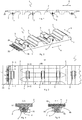
- the toothed belt 1 has a belt-shaped belt body 2, which carries on its one side molded tooth profiles 3, which are arranged distributed uniformly in the longitudinal direction 4 of the toothed belt 1. Die Zahnprofile 1 hrs. are.
- the toothed belt 1 according to the embodiment shown in the figures is characterized in that in a plurality of tooth profiles 3 or even in each of the tooth profiles 3 at least one support roller 5 is integrated, the running surface 6 protrudes beyond the top surface 7 of the associated tooth profile 3 (see example FIG. 4 ), so that the toothed belt 1 can be supported on the support rollers 5 on a guide rail, not shown in the figures. Such as from the Figures 2 .
- a support roller 5 is integrated in every second tooth profile 3 of the toothed belt 1, wherein in the embodiment according to the FIG. 19 even two support rollers 5 are accommodated in a tooth profile 3.
- a support roller 5 may be integrated, as for example in FIG. 20 is shown. Conceivable, however, are embodiments in which only in every third or fourth or every nth, ie integer multiples, tooth profile 3, a support roller 5 is integrated to support the toothed belt 1. However, it has proven to be advantageous to integrate a support roller 5 at least in every second tooth profile 3.
- FIGS. 1 to 10 show in a schematic way a toothed belt 1, in which a first principle of a possible storage of the support rollers 5 is used, whereas the FIGS. 11 to 18 show a toothed belt 1, which has another principle of a possible storage of the support rollers 5. More specifically, the storage of the support rollers 5 takes place in the in the FIGS. 1 to 10 shown embodiment according to the principle of an axis, whereas in the in the FIGS. 11 to 18 shown embodiment, the storage is carried out according to the principle of a shaft.
- each second tooth profile 3 has a respective recess 8 (see for example FIG. 7 or 9 ), which is formed in relation to the width direction 9 of the toothed belt 1 in the center of an associated tooth profile 3 and in which a corresponding support roller 5 is arranged.
- a respective recess 8 thus shares the associated tooth profile 3 in tooth profile sections 3a and 3b, in which the associated support roller 5 is rotatably supported.
- FIG. 3 shows, which in turn is a plan view of a portion of the toothed belt 1 according to the invention. Except for this protruding portion of the tread 6, the in FIG.
- the support rollers 5 are completely within the cross-sectional shape of the respective tooth profiles 3 and the cross-sectional shape of the associated tooth profile sections 3a, 3b added, so that only over the top surface 7 of the respective tooth profiles 3 protruding portion 80 of the respective tread 6 of the associated support roller 5 comes into contact with a guide rail to support the toothed belt 1.
- a respective support roller 5 is rotatably mounted via an axis 11 fixed in the associated tooth profile 3.
- the tooth profile sections 3a and 3b have bores 12a and 12b which receive the longitudinal ends of the axle 11.
- the axle 11, which may be made of steel, is designed at a first longitudinal end 11a as a screw with a threaded portion 11b, so that the axle 11 can be axially secured against slipping out of the bore 12a.
- the diameter of the other bore 12b is slightly smaller than the diameter of the associated second longitudinal end 11c of the axle 11.
- first longitudinal end 11a of the axle 11 is fixed via a kind of threaded connection 14 in the tooth profile section 3a of the associated tooth profile 3, whereas the second longitudinal end 11c the axis 11 is fixed in a press-fit connection 15 in the other tooth profile section 3b of the associated tooth profile 3.
- the axis 11 used in this embodiment is in one piece and corresponds more or less to a special screw with a long cylindrical pin.
- the inclusion of the axis 11 in the tooth profile section 3b in the form of the bore 12b may be performed as well as the bore 12a as a through hole. Manufacturing technology consuming but quite feasible, the bore 12a could alternatively be designed as a blind hole.
- the respective through holes 12a and 12b in the illustrated embodiment have the advantage that both sides of the toothed belt 1 can be drilled and the chips can be better removed from the bores 12a, 12b during machining.
- a narrow trained support roller 5 is provided, wherein the ratio of axial length 16 of the support roller 5 to the belt width 17 in the illustrated embodiment 0.4 (see, for example FIG. 3 ), but also deviating ratio are possible, but should be at least 0.1.
- the axis 11 could be omitted and the support roller 5 instead be designed as a skid.
- the material of the runner to the guide rail less friction than the material of the toothed belt 1, which is preferably polyurethane, produced.
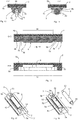
- each second tooth profile 3 has a respective recess 8, which is formed in the middle of the associated tooth profile 3 with respect to the width direction 9 of the toothed belt 1 and the corresponding support roller 5 receives. Also here also shares a respective recess 8, the associated tooth profile 3 in the tooth profile sections 3a, 3b, which receive the associated support roller 5 rotatably.
- a respective recess 8 also has a cup-shaped contour in this embodiment, the sections 8a, 8b extending in the width direction 9 partially following the cross-sectional shape of the tooth profile sections 3a, 3b or corresponding to sections of the original tooth profile 3, such as, in particular FIG. 14 shows a sectional view along the line FF in FIG. 12 is, which in turn is a plan view of the toothed belt 1.
- the recess 8 in a respective tooth profile 3 extends here as well into the belt body 2 and ends just above the longitudinal reinforcing strands 70 (see, for example FIG. 14 ).
- a respective support roller 5 projects with a maximum of one third of its radius 10 beyond the top surface 7 of the associated tooth profile 3.
- the radius 10 is in FIG.
- FIG. 12 shown making a cut along the line EE FIG. 12 shows. Except for this protruding section 80 (see, for example FIG. 14 ) of the tread 6, the support rollers 5 are completely included in the cross-sectional shape of the respective tooth profiles 3 and the cross-sectional shape of the associated tooth profile sections 3a, 3b, so that only the over the top surface 7 of the respective tooth profiles 3 protruding portion 80 of the respective tread 6 of the associated support roller 5 comes into contact with the guide rail.
- the bearing of the support roller 5 is designed according to the principle of a shaft.
- a respective support roller 5 for rotatable mounting serving stub shaft 50 formed, such as out FIG. 18 is apparent.
- the two stub shafts 50 are clipped during assembly in associated snap-51, which are formed in the tooth profile sections 3a, 3b.
- the snap connections 51 comprise elastically deformable retaining arms 52 which allow the stub shafts 50 to be pressed into a respective receiving space 53 formed in the tooth profile sections 3a and 3b, respectively.
- a gap 55 is present, which is smaller than the diameter of the associated stub shaft 50, so that a respective stub shaft 50 after mounting the associated support roller 5 on the timing belt 1 on slip out of the corresponding receiving space 53 is prevented.
- the retaining arms 52 additionally provide slots 54 which extend in the head surface 7 of the tooth profile 3 in the longitudinal direction 4 and limit the retaining arms 52 in the width direction 9.
- intermediate substances or intermediate bodies can be used to minimize the friction between the stub shafts 50 and the receiving spaces 53.
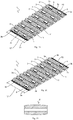
- FIG. 19 shows a further possible embodiment of a toothed belt 1, in which the arranged in the recesses 8 support rollers 5 are arranged in the longitudinal direction 4 of the toothed belt 1 in two rows aligned one behind the other.
- two recesses 8 with respective support roller 5 are provided side by side in the width direction 9 of the toothed belt 1 in each second tooth profile 3, wherein in this example recesses 8 are formed only in each second tooth profile 3.
- two recesses 8 with support rollers 5 can be provided in each tooth profile 3.
- the two recesses 8 divide the tooth profile 3 into tooth profile sections 3a, 3b, 3c, wherein the two support rollers 5 per tooth profile 5 are supported and held by a common axis 11.
- the axis 11 is fixed with its first longitudinal end, which is designed as a screw in the manner of a threaded connection in the tooth profile section 3a, while the second longitudinal end of the axle 11 is fixed via a press fit in the tooth profile section 3b. Between its longitudinal ends, the axis 11 is held by the tooth profile section 3 c, which is arranged between two support rollers 5 of an associated tooth profile 3.
- the ratio of axial length 16 of a respective support roller 5 (the axial length of the support roller 5 in FIG.
- FIG. 20 shows a further modification in which in each tooth profile 3, a recess 8 is formed with support roller 5 mounted therein. Unlike the in FIG. 19 As shown embodiment, the integrated in the tooth profiles 3 support rollers 5 are no longer aligned. Rather, the arranged in the recesses 8 adjacent tooth profiles 3 support rollers 5 in the width direction 9 are offset from one another arranged that the integrated in each second tooth profile 3 support rollers 5 are arranged in the longitudinal direction 4 in alignment with each other.
- FIGS. 19 and 20 shown embodiments, in which the bearing of a respective support roller 5 is designed according to the principle of an axis, also on the principle of storage of a shaft (see FIGS. 11 to 18 ) is transferable. It is also possible to mix the storage principles in a toothed belt, so that support rollers 5 are provided both according to the principle of storage of an axle and according to the principle of storage of a shaft.
- FIGS. 19 and 20 shown ways of providing a support roller 5 in each tooth profile 3 or two support rollers 5 in each second tooth profile 3, purely exemplary way.
- the number of support rollers 3, which is integrated in a tooth profile 3 depends on the belt width and the type of use of the belt from.
- arrangements of two alternately three and three support rollers 5 per tooth profile 3 are conceivable, wherein the support rollers 5 may be arranged offset from one another. Arrangements are therefore possible in which the number of support rollers from tooth profile 3 to tooth profile 3 is different. It will thus be understood that the invention is not limited to the embodiments shown in the figures, but modifications and uses of features of one embodiment shown in the other embodiment are possible.
- the support roller 5 in the embodiments described above has a cylindrical shape.
- a support roller 5 ' which is viewed in an axial section is spherical and designed for the storage principle of the axle.
- the spherical shape of the support roller 5 ' also on the support rollers with stub shaft 50, so on the storage principle in the manner of a wave, transferable.
- the barrel shape is compared to cylindrical support rollers friction and less sensitive to edge wear, wherein Also, a combination is possible, the spherical support rollers 5 'and cylindrical support rollers 5 used in a toothed belt 1.
- a stamped image 90 which serves to develop a finite toothed belt by welding the longitudinal ends 18a and 18b of the toothed belt 1 together.
- the respective longitudinal ends 18a, 18b of the toothed belt 1 have comb-shaped and complementary to each other formed tongues or punching fingers 19a and 19b, which are arranged interlocking to form an endless belt and welded together (see FIG. 10 which is representative of both embodiments).
- the punching fingers 19a, 19b are formed by manufacturing technology through recesses, which are formed in the longitudinal ends 18a, 18b of the toothed belt. How further the FIG.
- the punching image 90 extends in the longitudinal direction 4 of the toothed belt 1 and three tooth profiles 3 with support rollers 5. But also conceivable punching images with a smaller or larger longitudinal extent 91 than those in the FIG. 3 is shown.
- the position of the tension members or reinforcing strands 70 has to be "punch-friendly", which means that no reinforcing strands 70 are longitudinally arranged in the region of a punching line 90 extending in the longitudinal direction 4. This is also the reason why the distances between the reinforcing strands 70 are uneven, such as the Figures 3 and 12 can be seen.
- the cavities of the recesses 8 must be designed so that they are demoldable and do not hinder the welding process.
- At least one support roller 5 is integrated in at least one tooth profile 3, wherein a respective support roller 5 exclusively with a section 80 its tread 6 projects beyond the top surface 7 of the associated tooth profile 3. Only with this section 80 is a respective support roller 5 protruding from the cross section of a respective tooth profile 3, so that the function of the actual tooth profile 3 is still ensured.
- a toothed belt 1 is shown with T-profile. Such a toothed belt carries on the toothed pulley on the belt tooth space. The belt tooth head does not rest in the toothed pulley.
- the existing air is greater than the supernatant of the down from the belt teeth looking out support rollers 5, so that a normal standard toothed disk can be used.
- the AT profile carries over the heads of the teeth.
- the gap bottom of the toothed discs must be adjusted so that in each second tooth gap a cylinder portion is cleared, in which the support roller 5 is immersed, provided that each second tooth profile 3 is equipped with a support roller 5. As a result, only integer numbers of teeth of the toothed disc are allowed.
Landscapes
- Engineering & Computer Science (AREA)
- Mechanical Engineering (AREA)
- General Engineering & Computer Science (AREA)
- Devices For Conveying Motion By Means Of Endless Flexible Members (AREA)
Description
- Die Erfindung betrifft einen Zahnriemen zum Transportieren von Objekten, aufweisend einen bandförmigen Riemenkörper, der auf seiner einen Seite angeformte Zahnprofile trägt, die in Längsrichtung des Zahnriemens gleichmäßig verteilt angeordnet sind.
- Ein Zahnriemen der Eingangs bezeichneten Art ist aus dem Stand der Technik bekannt und wird in der
DE 20 2012 100 232 U1 beschrieben. Solche Zahnriemen werden in vielen Fällen heute nicht mehr nur als reines Zugmittelgetriebe, sondern auch als hochpräzises Fördermittel für Bauteile in einer automatisierten Produktion genutzt. Dabei werden sie quasi wie ein genau steuerbares, schmales Förderband verwendet. Derartige Transporteinrichtungen sind dann in der Regel recht lang, so dass Riemenlängen von mehr als fünfzig Metern keine Seltenheit sind. Die Zahnriemen werden im Obertrum in Führungsschienen geführt, damit bei Belastung durch die zu transportierenden Produkte kein Durchhang entsteht und im Start-Stopp-Betrieb keine Schwingungen des Zahnriemens auftreten. Durch die Gewichtsbelastung der Bauteile des Riementriebs, aber auch durch das Riemen-Eigengewicht entsteht auf diesen Führungsschienen eine Normalbelastung, die in Kombination mit dem vorherrschenden Reibbeiwert bei Bewegung zu einer Verlustleistung führt. Diese Verlustleistung vergrößert zum einen die erforderliche Antriebsleistung und den Energieverbrauch der Anlage. Zum anderen erwärmt sie den Zahnriemen in Abhängigkeit der Riemenlänge, der Bauteilgewichte und Geschwindigkeiten so sehr, dass die Standzeit der Zahnriemen deutlich sinkt, was unter anderem dadurch begründet ist, dass die Zugfestigkeit von thermoplastischem Polyurethan als Werkstoff der Zahnriemen mit steigender Temperatur überproportional stark abnimmt. - Die aus dem Stand der Technik bekannten Lösungsansätze zielen darauf ab, den Reibbeiwert zwischen Zahnriemen und Führungsschiene zu reduzieren. Schienenseitig werden heute polierte Edelstahlbleche und spezielle Kunststoffe mit günstigen Reibeigenschaften im Kontakt mit Polyurethan eingesetzt. Riemenseitig werden auf der Zahnprofilseite Gewebebeschichtungen eingesetzt, die den Reibbeiwert im Neuzustand zwar deutlich senken, aufgrund von Verschleiß aber nur eine zeitlich begrenzte Wirksamkeit haben. In der Summe sind diese möglichen Maßnahmen nicht zufriedenstellend, denn bei höheren Geschwindigkeiten, Lasten und Betriebstemperaturen versagt das System. Nachteilig kommt hinzu, dass im Lebensmittelbereich der Verschleiß von Gewebe und Führungsschiene stört, weil eine Kontamination der Lebensmittel mit Abrieb nicht ausgeschlossen werden kann.
- Um diese bekannten Nachteile zu vermeiden, ist es aus dem Stand der Technik bekannt, von Gleit- zu Rollreibung überzugehen, sofern man die im Hertz'schen Rollkontakt entstehenden Flächenpressungen beherrscht.
- Aus anderen Transportbereichen sind dementsprechend Einrichtungen bekannt, bei denen das Rollelement in das stehende Teil integriert ist (zum Beispiel Kugellager oder Rolle in Führungsschiene). Beispielsweise beschreibt die
DE 20 2007 014 761 U1 ein System, bei dem ein Riemen mit Hilfe von Gleitschienen und Stützrollen gestützt und geführt ist. - Jedoch stellt bei Zahnriemen die Verzahnung ein Problem dar, so dass die aus dem Stand der Technik bekannten Maßnahmen nicht übertragbar sind. Denn um Zahneingriffsstößen zu entgehen, müssten entweder sehr viele schmale Stützrollen über der Breite versetzt in den Führungsschienen angeordnet werden, so dass jedes Zahnprofil immer irgendwo auf der Riemenbreite und Riemenlänge Unterstützung durch eine Stützrolle erfährt. Oder es müssten glatte, zahnfreie Längsspuren auf dem Zahnriemen vorgesehen sein, in denen über der Breite mehrere (mindestens zwei) kugellagerähnliche schmale Stützrollen laufen und für die Abstützung sorgen. Beide Möglichkeiten sind aber aufwändig und mit technischen Kompromissen behaftet.
- Ausgehend von dem bekannten Stand der Technik liegt der Erfindung die Aufgabe zugrunde eine Lösung zu schaffen, die auf konstruktiv einfache Weise einen verbesserten Zahnriemen zum Transportieren von Objekten bereitstellt, welcher die aus dem Stand der Technik bekannten Probleme vermeidet und eine Möglichkeit einer wirkungsvollen Abstützung der Zahnprofilseite eines Zahnriemens bietet.
- Bei einem Zahnriemen der Eingangs bezeichneten Art wird die Aufgabe erfindungsgemäß dadurch gelöst, dass wenigstens ein Zahnprofil zumindest eine Aussparung aufweist, in der eine Stützrolle angeordnet ist, deren Lauffläche zur Abstützung des Zahnriemens über die Kopffläche des zugehörigen Zahnprofiles hinausragt.
- Vorteilhafte und zweckmäßige Ausgestaltungen und Weiterbildungen der Erfindung ergeben sich aus den Unteransprüchen.
- Durch die Erfindung wird ein Zahnriemen zur Verfügung gestellt, welcher sich durch eine funktionsgerechte Konstruktion auszeichnet. Im Unterschied zum bekannten Stand der Technik ist erfindungsgemäß das rollende Element in Form der Stützrolle in das bewegliche Teil, den Zahnriemen, integriert. Die in den Zahnprofilen integrierten Stützrollen stützen den Zahnriemen auf Führungsschienen eines Transportsystems ab und vermeiden Schwingungen beim Anfahren und Abstoppen des Zahnriemens. Darüber hinaus reduziert die durch die Stützrollen gegebene Abstützung die Reibungsverluste, so dass der erfindungsgemäße Zahnriemen eine geringere Antriebsenergie benötigt als die aus dem Stand der Technik bekannten Systeme, bei denen der Riemen reibungsbehaftet in einer Schiene gestützt und geführt ist. Der erfindungsgemäße Ansatz, Stützrollen in den Zahnriemen zu integrieren, über die der Zahnriemen abgestützt ist und rollend bewegt wird, erhöht darüber hinaus die Standzeit des Zahnriemens, da sich dieser aufgrund der Rollreibung nicht mehr derart erwärmt, wie es bei den Riemen der Fall ist, die über die Gleitreibung in Führungsschienen geführt werden. Insbesondere entfällt mit der erfindungsgemäßen Ausbildung des Zahnriemens eine aufwendige Abstützung der Zahnprofilseite mittels mehrerer, ortsfest an der Führungsschiene befestigter Rollen. Da die jeweiligen Aussparungen das Zahnprofil und damit den Zahnriemen schwächen, sind die Aussparungen mit den darin angeordneten Stützrollen zumindest in einigen der Zahnprofile ausgebildet, wobei es auch denkbar ist, jedes Zahnprofil mit einer Aussparung und einer der Abstützung dienenden Stützrolle auszubilden. Natürlich umfasst die Erfindung auch Ausgestaltungen, bei denen entweder jedes Zahnprofil oder jedes n-te (ganzzahlige Vielfache, wie zum Beispiel jedes zweite, dritte, vierte usw.) Zahnprofil mehr als eine Aussparung aufweisen kann. Die Anzahl der Aussparungen und damit der Stützrollen je Zahnprofil kann in Abhängigkeit der Riemenbreite gewählt werden, so dass es durchaus sinnvoll ist, bei breiten Zahnriemen mehrere Stützrollen je Zahnprofil vorzusehen.
- Eine konstruktiv günstige Möglichkeit, eine jeweilige Stützrolle in einem Zahnprofil zu integrieren, besteht in Ausgestaltung der Erfindung darin, dass die zumindest eine Aussparung in Bezug auf die Breitenrichtung des Zahnriemens das zugehörige Zahnprofil in Zahnprofilabschnitte teilt, wobei die der Aussparung zugehörige Stützrolle in den angrenzenden Zahnprofilabschnitten des zugehörigen Zahnprofiles drehbar gehalten ist.
- Aus Stabilitätsgründen der Zahnprofile ist es in Ausgestaltung der Erfindung von Vorteil, dass eine jeweilige Stützrolle mit höchstens einem Drittel ihres Radius über die Kopffläche des zugehörigen Zahnprofiles hinausragt. Insbesondere ragt eine jeweilige Stützrolle ausschließlich über die Kopffläche und nicht über die Flankenseiten des zugehörigen Zahnprofiles hinaus, so dass die Stützrolle die Schwächung des Zahnprofiles infolge der Aussparung zumindest materialmäßig ausgleicht. Darüber hinaus fällt durch den geringen Überstand einer jeweiligen Stützrolle über die zugehörige Kopffläche der Aufwand zur Anpassung der Zahnscheibe gering aus. Denn ein Zahnriemen mit T-Profil trägt auf der Zahnscheibe über die Riemen-Zahnlücke, denn der Riemen-Zahnkopf liegt in der Scheibe nicht auf. Die vorhandene Luft ist größer als der Überstand der unten aus den Zahnprofilen herausschauenden Stützrollen, so dass eine ganz normale Standard-Zahnscheibe zum Einsatz kommen kann. Hingegen trägt ein Zahnriemen mit AT-Profil über die Zahnköpfe. Wenn jedes zweite Zahnprofil mit einer Stützrolle ausgestattet ist, dann muss hier der Lückengrund der Zahnscheiben so angepasst werden, dass in jeder zweiten Zahnlücke ein Zylinderabschnitt freigemacht wird, in den die Stützrolle eintaucht.
- Um die eine Schwächung des Zahnprofils darstellende Aussparung so gering und klein wie möglich zu halten, sieht die Erfindung in Ausgestaltung vor, dass eine jeweilige Aussparung in einem zugehörigen Zahnprofil eine schalenförmige und abschnittsweise der Kontur der in Breitenrichtung des Zahnriemens angrenzenden Zahnprofilabschnitte entsprechende Querschnittsform aufweist und sich bis in den Riemenkörper hinein erstreckt. Dabei ist die schalenförmige Kontur insbesondere der Lauffläche einer entsprechenden Stützrolle angepasst.
- Gemäß einer Ausführungsform der Erfindung besteht eine Möglichkeit der drehbaren Halterung einer Stützrolle darin, dass eine jeweilige Stützrolle über eine in dem zugehörigen Zahnprofil fixierte Achse drehbar gelagert ist. Hier dreht sich folglich die Stützrolle um die im Zahnprofil fixierte Achse.
- Bei einer solchen Ausführungsform ist es dann von Vorteil, wenn ein erstes Längsende der Achse über eine Gewindeverbindung in einem Zahnprofilabschnitt eines zugehörigen Zahnprofils fixiert ist und ein zweites Längsende der Achse in einer Presspassverbindung in dem anderen Zahnprofilabschnitt des zugehörigen Zahnprofils befestigt ist. Die Achse kann hierbei einseitig als Schraube ausgeführt und dementsprechend in einen Zahnprofilabschnitt eingeschraubt sein, um ein axiales Herausrutschen der Achse zu verhindern.
- Gemäß einer anderen Ausführungsform der Erfindung besteht eine Möglichkeit der drehbaren Halterung einer Stützrolle darin, dass endseitig an einer jeweiligen Stützrolle jeweils ein zur drehbaren Lagerung dienender Wellenstummel angeformt ist, wobei die Zahnprofilabschnitte jeweils eine Schnappverbindung zur Aufnahme und drehbaren Lagerung eines zugehörigen Wellenstummels aufweisen. Bei dieser Ausführungsform entfallen die Achse und damit ein Bauteil, da eine jeweilige Stützrolle mit zwei Wellenstummeln ausgeführt ist, welche die Lagerfunktion übernehmen. Da die Kräfte stets in Druckrichtung wirken, kann die Lagerung im Zahnriemen zahnseitig als offene Schnappverbindung gestaltet werden, so dass die Wellenstummel der Stützrollen bei Montage einfach nur eingeclipst werden müssen.
- Um die Schwächung der jeweiligen Zahnprofile mit der Aussparung so gering wie möglich zu halten, ist in Ausgestaltung der Erfindung ferner vorgesehen, dass das Verhältnis von axialer Länge einer jeweiligen Stützrolle zur Riemenbreite wenigstens 0,1 und höchstens 0,65 beträgt. Bei einer Lagerung der Stützrollen mittels einer jeweiligen Achse hat es sich als besonders günstig erwiesen, wenn das Verhältnis von axialer Länge einer jeweiligen Stützrolle zur Riemenbreite 0,2 beträgt, wohingegen sich bei der Lagerung mittels der Wellenstummel ein Verhältnis von axialer Länge einer jeweiligen Stützrolle zur Riemenbreite von 0,6 als vorteilhaft erwiesen hat.
- Um den erfindungsgemäßen Zahnriemen als Endlosriemen einsetzen zu können, sieht die Erfindung in weiterer Ausgestaltung vor, dass die Längsenden des Zahnriemens kammartig und komplementär zueinander ausgebildete Stanzfinger aufweisen, die ein vorbestimmtes Stanzbild definieren und die zur Bildung eines Endlosriemens ineinandergreifend angeordnet und miteinander verschweißt sind, wobei sich das Stanzbild in Längsrichtung des Zahnriemens über wenigstens zwei Zahnprofile mit Stützrollen erstreckt.
- Im Übrigen besteht der Zahnriemen vorzugsweise aus Polyurethan, wobei der Riemenkörper längsverlaufende Verstärkungslitzen aufweist, die aus Draht bestehen können, die aber in jedem Fall unterhalb einer jeweiligen Stützrolle verlaufen. Alternativ ist es auch denkbar, dass die Verstärkungslitzen ausschließlich seitlich neben einer jeweiligen Stützrolle verlaufen, wodurch es möglich ist, die Aussparung sehr tief in den Riemenkörper hineinreichend auszuformen.
- Insbesondere bei schmalen Zahnriemen hat es sich als günstig erwiesen, dass die in den Aussparungen angeordneten Stützrollen in Längsrichtung des Zahnriemens fluchtend hintereinanderliegend angeordnet sind, was einen ruhigen Betrieb des Zahnriemens ermöglicht.
- Zur Vermeidung von Schwingungen im Start-Stopp-Betrieb des Zahnriemens hat es sich als vorteilhaft erwiesen, wenn in jedem zweiten Zahnprofil des Zahnriemens zumindest eine eine Stützrolle aufnehmende Aussparung ausgebildet ist. Dadurch ist eine Abstützung des Zahnriemens ohne Durchhang gewährleistet.
- Alternativ zu einer fluchtenden Anordnung der Aussparungen mit den darin angeordneten Stützrollen sieht die Erfindung vor, dass die in den Aussparungen benachbarter Zahnprofile angeordneten Stützrollen in Längsrichtung des Zahnriemens in Breitenrichtung versetzt zueinander angeordnet sind. Dabei ist es unerheblich, ob in jedem Zahnprofil oder jedem zweiten oder dritten Zahnprofil eine oder mehrere Aussparungen angeordnet sind. Es kommt nur darauf an, das Stützrollen in benachbarten Zahnprofilen versetzt zueinander angeordnet sind.
- Um einen Durchhang des Zahnriemens in jedem Fall auszuschließen, sieht die Erfindung in vorteilhafterweise vor, dass in jedem Zahnprofil des Zahnriemens zumindest eine eine Stützrolle aufnehmende Aussparung ausgebildet ist.
- Schließlich sieht die Erfindung in weiterer Ausgestaltung vor, dass wenigstens eine Stützrolle in einem Axialschnitt betrachtet ballig ausgebildet ist. Die Stützrollen können also eine leichte Tonnenform aufweisen, wenn sie im Axialschnitt ballig ausgebildet sind. Die ballige Form hat den Vorteil, dass sie im Vergleich zu einer rein zylindrischen Querschnittsform der Stützrolle reibungsärmer und weniger empfindlich gegen Kantentragen ist. Selbstverständlich kommen auch Stützrollen in Frage, die im Axialschnitt betrachtet trapezförmig ausgebildet sind. Auch ist es vorstellbar, dass bei einem Zahnriemen eine Mischung aus rein zylindrischen und ballig ausgebildeten Stützrollen zum Einsatz kommt.
- Es versteht sich, dass die vorstehend genannten und nachstehend noch zu erläuternden Merkmale nicht nur in der jeweils angegebenen Kombination, sondern auch in anderen Kombinationen oder in Alleinstellung verwendbar sind, ohne den Rahmen der vorliegenden Erfindung zu verlassen. Der Rahmen der Erfindung ist nur durch die Ansprüche definiert.
- Weitere Einzelheiten, Merkmale und Vorteile des Gegenstandes der Erfindung ergeben sich aus der nachfolgenden Beschreibung im Zusammenhang mit der Zeichnung, in der beispielhafte bevorzugte Ausführungsbeispiele der Erfindung dargestellt sind. In der Zeichnung zeigt:
-
Figur 1 eine Seitenansicht auf einen Abschnitt eines erfindungsgemäßen Zahnriemens, -
Figur 2 eine Perspektivansicht auf einen Abschnitt des erfindungsgemäßen Zahnriemens, -
Figur 3 eine Draufsicht auf einen Abschnitt des erfindungsgemäßen Zahnriemen, -
Figur 4 eine Schnittansicht des Zahnriemens entlang der Linie A-A inFigur 3 , -
Figur 5 eine Schnittansicht des Zahnriemens entlang der Linie B-B inFigur 3 , -
Figur 6 eine Perspektivansicht auf einen Abschnitt des Zahnriemens mit der in einem Zahnprofil gelagerten Stützrolle, -
Figur 7 der inFigur 6 gezeigte Abschnitt des Zahnriemens in einer perspektivischen Einzelteildarstellung, -
Figur 8 eine Schnittansicht des Zahnriemens entlang der Linie C-C inFigur 3 für eine Lagerungsmöglichkeit einer im Zahnprofil aufgenommenen Stützrolle, -
Figur 9 eine Schnittansicht des Zahnriemens entlang der Linie D-D inFigur 3 unter Auslassung der Stützrolle, -
Figur 10 in perspektivischer Ansicht kammartige Längsenden des erfindungsgemäßen Zahnriemens entsprechend einem ausFigur 3 ersichtlichen Stanzbild, -
Figur 11 eine Perspektivansicht auf einen Abschnitt eines erfindungsgemäßen Zahnriemens mit alternativer Möglichkeit der Lagerung der Stützrollen, -
Figur 12 eine Draufsicht auf einen Abschnitt des Zahnriemens mit alternativer Möglichkeit der Lagerung der Stützrollen, -
Figur 13 eine Schnittansicht des Zahnriemens entlang der Linie E-E inFigur 12 , -
Figur 14 eine Schnittansicht des Zahnriemens entlang der Linie F-F inFigur 12 , -
Figur 15 eine Schnittansicht des Zahnriemens entlang der Linie G-G inFigur 12 , -
Figur 16 eine Schnittansicht des Zahnriemens entlang der Linie H-H inFigur 12 unter Auslassung einer Stützrolle, -
Figur 17 eine Perspektivansicht auf einen Abschnitt des Zahnriemens mit alternativer Möglichkeit der Lagerung der Stützrollen, -
Figur 18 der inFigur 17 gezeigte Abschnitt des Zahnriemens in einer perspektivischen Einzelteildarstellung, -
Figur 19 eine Perspektivansicht auf eine Ausführungsform des erfindungsgemäßen Zahnriemens mit zwei Stützrollen in einem Zahnprofil, -
Figur 20 eine Perspektivansicht auf eine Ausführungsform des erfindungsgemäßen Zahnriemens mit in Breitenrichtung versetzt zueinander angeordneten Stützrollen und -
Figur 21 eine Schnittansicht auf eine im Axialschnitt betrachtet ballig ausgebildete Stützrolle. - Die
Figuren 1 bis 21 zeigen in schematischer Weise einen erfindungsgemäßen Zahnriemen 1 bzw. Ausschnitte und verschiedene Ansichten eines solchen Zahnriemens 1. Der erfindungsgemäße Zahnriemen 1 weist einen bandförmigen Riemenkörper 2 auf, der auf seiner einen Seite angeformte Zahnprofile 3 trägt, die in Längsrichtung 4 des Zahnriemens 1 gleichmäßig verteilt angeordnet sind. Der Zahnriemen 1 gemäß der in den Figuren gezeigten Ausführungsform ist dadurch charakterisiert, dass in einer Vielzahl von Zahnprofilen 3 oder sogar in jedem der Zahnprofile 3 mindestens eine Stützrolle 5 integriert ist, deren Lauffläche 6 über die Kopffläche 7 des zugehörigen Zahnprofiles 3 hinausragt (siehe zum BeispielFigur 4 ), damit sich der Zahnriemen 1 über die Stützrollen 5 auf einer in den Figuren nicht dargestellten Führungsschiene abstützen kann. Wie beispielsweise aus denFiguren 2 ,11 und19 erkennbar ist, ist in jedem zweiten Zahnprofil 3 des Zahnriemens 1 eine Stützrolle 5 integriert, wobei bei der Ausführung gemäß derFigur 19 sogar zwei Stützrollen 5 in einem Zahnprofil 3 untergebracht sind. Selbstverständlich kann auch in jedem der Zahnprofile 3 eine Stützrolle 5 integriert sein, wie es beispielsweise inFigur 20 gezeigt ist. Denkbar sind aber auch Ausführungen, bei denen nur in jedem dritten oder vierten oder in jedem n-ten, d.h. ganzzahlig Vielfachen, Zahnprofil 3 eine Stützrolle 5 zur Abstützung des Zahnriemens 1 integriert ist. Es hat sich jedoch als günstig herausgestellt, wenigstens in jedem zweiten Zahnprofil 3 eine Stützrolle 5 zu integrieren. - Die
Figuren 1 bis 10 zeigen in schematischer Weise einen Zahnriemen 1, bei dem ein erstes Prinzip einer möglichen Lagerung der Stützrollen 5 zum Einsatz kommt, wohingegen dieFiguren 11 bis 18 einen Zahnriemen 1 zeigen, der ein anderes Prinzip einer möglichen Lagerung der Stützrollen 5 aufweist. Genauer gesagt erfolgt die Lagerung der Stützrollen 5 bei der in denFiguren 1 bis 10 gezeigten Ausführungsform nach dem Prinzip einer Achse, wohingegen bei der in denFiguren 11 bis 18 gezeigten Ausführungsform die Lagerung nach dem Prinzip einer Welle ausgeführt ist. - Mit Bezug auf die
Figuren 1 bis 10 weist jedes zweite Zahnprofil 3 eine jeweilige Aussparung 8 auf (siehe zum BeispielFigur 7 oder 9 ), die in Bezug auf die Breitenrichtung 9 des Zahnriemens 1 mittig eines zugehörigen Zahnprofiles 3 ausgebildet ist und in welcher eine entsprechende Stützrolle 5 angeordnet ist. Eine jeweilige Aussparung 8 teilt folglich das zugehörige Zahnprofil 3 in Zahnprofilabschnitte 3a und 3b, in denen die zugehörige Stützrolle 5 drehbar gehalten ist. Dabei weist eine jeweilige Aussparung 8 eine schalenförmige Kontur auf, wobei in Breitenrichtung 9 verlaufende Abschnitte 8a, 8b abschnittsweise der Querschnittsform der Zahnprofilabschnitte 3a, 3b folgen bzw. Abschnitten des ursprünglichen Zahnprofils 3 entsprechen, wie beispielsweise ausFigur 5 ersichtlich ist, die einen Schnitt entlang der Linie B-B inFigur 3 zeigt. Wie ebenfalls derFigur 3 zu entnehmen ist, erstreckt sich die Aussparung 8 in dem dargestellten Ausführungsbeispiel bis in den Riemenkörper 2 hinein und endet knapp oberhalb von längsverlaufenden Verstärkungslitzen 70, so dass diese auch im Bereich der Stützrollen 5 verlaufen. Natürlich sind auch Abwandlungen dieser Ausführungsform möglich, bei denen keine Verstärkungslitzen 70 im Bereich unterhalb der Stützrolle 5 angeordnet sind, so dass sich die Aussparung 8 noch tiefer in den Riemenkörper 2 hinein erstrecken kann. - Eine jeweilige Stützrolle 5 ragt mit maximal einem Drittel (siehe hierzu die
Figuren 4 und 5 ) ihres Radius 10 über die Kopffläche 7 des zugehörigen Zahnprofils 3 hinaus, wie beispielsweise ausFigur 4 ersichtlich ist, die einen Schnitt entlang der Linie A-A ausFigur 3 zeigt, die wiederum eine Draufsicht auf einen Abschnitt des erfindungsgemäßen Zahnriemens 1 ist. Bis auf diesen hervorstehenden Abschnitt der Lauffläche 6, der inFigur 5 mit dem Bezugszeichen 80 kenntlich gemacht ist, sind die Stützrollen 5 vollständig innerhalb der Querschnittsform der jeweiligen Zahnprofile 3 bzw. der Querschnittsform der zugehörigen Zahnprofilabschnitte 3a, 3b aufgenommen, so dass nur der über die Kopffläche 7 der jeweiligen Zahnprofile 3 hinausragende Abschnitt 80 der jeweiligen Lauffläche 6 der zugeordneten Stützrolle 5 in Kontakt mit einer Führungsschiene tritt, um den Zahnriemen 1 abzustützen. - Gemäß der in den
Figuren 1 bis 10 gezeigten Ausführungsform ist eine jeweilige Stützrolle 5 über eine in dem zugehörigen Zahnprofil 3 fixierte Achse 11 drehbar gelagert. Zu diesem Zweck weisen die Zahnprofilabschnitte 3a und 3b Bohrungen 12a und 12b auf, welche die Längsenden der Achse 11 aufnehmen. Die Achse 11, die aus Stahl bestehen kann, ist an einem ersten Längsende 11a als Schraube mit einem Gewindeabschnitt 11b ausgeführt, damit die Achse 11 axial gegen Herausrutschen aus der Bohrung 12a gesichert werden kann. Der Durchmesser der andere Bohrung 12b ist geringfügig kleiner als der Durchmesser des zugehörigen zweiten Längsendes 11c der Achse 11. Folglich ist das erste Längsende 11a der Achse 11 über eine Art Gewindeverbindung 14 in dem Zahnprofilabschnitt 3a des zugehörigen Zahnprofils 3 fixiert, wohingegen das zweite Längsende 11c der Achse 11 in einer Presspassverbindung 15 in dem anderen Zahnprofilabschnitt 3b des zugehörigen Zahnprofils 3 befestigt ist. - Die bei dieser Ausführungsform verwendete Achse 11 ist einteilig und entspricht quasi einer Sonderschraube mit langem zylindrischem Zapfen. Die Aufnahme der Achse 11 im Zahnprofilabschnitt 3b in Form der Bohrung 12b kann ebenso wie die Bohrung 12a als Durchgangsbohrung ausgeführt sein. Fertigungstechnich aufwendiger aber durchaus realisierbar, könnte die Bohrung 12a alternativ auch als ein Sackloch ausgeführt sein. Jedoch haben die jeweiligen Durchgangsbohrungen 12a und 12b in dem dargestellten Ausführungsbeispiel den Vorteil, dass beidseitig des Zahnriemens 1 gebohrt werden kann und die Späne bei der Bearbeitung besser aus den Bohrungen 12a, 12b entfernt werden können.
- Um die Schwächung der Zahnprofile 3 mit einer Aussparung 8 so gering wie möglich zu halten, ist unter anderem für das Lagerungsprinzip über die Achse 11 gemäß der
Figuren 1 bis 10 eine schmal ausgebildete Stützrolle 5 vorgesehen, wobei das Verhältnis von axialer Länge 16 der Stützrolle 5 zur Riemenbreite 17 in dem dargestellten Ausführungsbeispiel 0,4 (siehe beispielsweiseFigur 3 ) beträgt, wobei auch davon abweichende Verhältnis möglich sind, die aber wenigstens 0,1 betragen sollten. - Um ferner die Reibung zwischen der jeweiligen Achse 11 und der zugehörigen Stützrolle 5 zu minimieren ist der Einsatz von Zwischenstoffen oder Zwischenkörpern denkbar. Demnach könnten kleine Gleitlager, Mini-Nadellager oder Gleitlackschichten mit schmierender Wirkung zusätzlich vorgesehen sein, um Reibungsverluste zwischen Achse 11 und Stützrolle 5 zu minimieren.
- Als Alternative zu dem Lagerungsprinzip der Stützrolle 5 über die Achse 11 könnte die Achse 11 entfallen und die Stützrolle 5 stattdessen als Gleitkufe ausgebildet sein. Eine solche Alternative ist aber nur dann sinnvoll, wenn das Material der Kufe zur Führungsschiene weniger Reibung als das Material des Zahnriemens 1, welches vorzugsweise Polyurethan ist, erzeugt.
- Eine weitere Alternative zu dem Lagerungsprinzip über die Achse 11 ist in den Ausführungsformen der
Figuren 11 bis 18 gezeigt. Auch bei dieser Ausführungsform des Zahnriemens 1, der sich durch das Prinzip der Lagerung der Stützrolle 5 von dem Zahnriemen derFiguren 1 bis 10 unterscheidet, weist jedes zweite Zahnprofil 3 eine jeweilige Aussparung 8 auf, die in Bezug auf die Breitenrichtung 9 des Zahnriemens 1 mittig des zugehörigen Zahnprofiles 3 ausgebildet ist und die entsprechende Stützrolle 5 aufnimmt. Ebenfalls teilt auch hier eine jeweilige Aussparung 8 das zugehörige Zahnprofil 3 in die Zahnprofilabschnitte 3a, 3b, welche die zugehörige Stützrolle 5 drehbar aufnehmen. Eine jeweilige Aussparung 8 weist bei dieser Ausführungsform ebenso eine schalenförmige Kontur auf, wobei die in Breitenrichtung 9 verlaufenden Abschnitte 8a, 8b abschnittsweise der Querschnittsform der Zahnprofilabschnitte 3a, 3b folgen bzw. Abschnitten des ursprünglichen Zahnprofils 3 entsprechen, wie insbesondere dieFigur 14 zeigt, die eine Schnittdarstellung entlang der Linie F-F inFigur 12 ist, die wiederum eine Draufsicht auf den Zahnriemen 1 ist. Die Aussparung 8 in einem jeweiligen Zahnprofil 3 erstreckt sich auch hier bis in den Riemenkörper 2 hinein und endet knapp oberhalb der längsverlaufenden Verstärkungslitzen 70 (siehe zum BeispielFigur 14 ). Ebenso ragt eine jeweilige Stützrolle 5 mit maximal einem Drittel ihres Radius 10 über die Kopffläche 7 des zugehörigen Zahnprofils 3 hinaus. Der Radius 10 ist inFigur 13 dargestellt, die einen Schnitt entlang der Linie E-E ausFigur 12 zeigt. Bis auf diesen hervorstehenden Abschnitt 80 (siehe zum BeispielFigur 14 ) der Lauffläche 6 sind die Stützrollen 5 auch bei dieser Ausführungsform vollständig innerhalb der Querschnittsform der jeweiligen Zahnprofile 3 bzw. der Querschnittsform der zugehörigen Zahnprofilabschnitte 3a, 3b aufgenommen, so dass nur der über die Kopffläche 7 der jeweiligen Zahnprofile 3 hinausragende Abschnitt 80 der jeweiligen Lauffläche 6 der zugeordneten Stützrolle 5 in Kontakt mit der Führungsschiene tritt. - Wie die
Figuren 11 bis 18 für die weitere Ausführungsform zeigen, ist die Lagerung der Stützrolle 5 nach dem Prinzip einer Welle ausgeführt. Zu diesem Zweck ist endseitig an einer jeweiligen Stützrolle 5 jeweils ein zur drehbaren Lagerung dienender Wellenstummel 50 angeformt, wie zum Beispiel ausFigur 18 ersichtlich ist. Die beiden Wellenstummel 50 werden bei der Montage in zugeordnete Schnappverbindungen 51 eingeclipst, die in den Zahnprofilabschnitten 3a, 3b ausgeformt sind. Die Schnappverbindungen 51 umfassen elastisch verformbare Rückhaltearme 52, die ein Eindrücken der Wellenstummel 50 in einen jeweiligen Aufnahmeraum 53, der in dem Zahnprofilabschnitt 3a bzw. 3b ausgebildet ist, ermöglichen. Zwischen den beiden Rückhaltearmen 52, die an den jeweiligen Zahnprofilabschnitten 3a, 3b ausgebildet sind, ist ein Zwischenraum 55 vorhanden, der kleiner als der Durchmesser des zugeordneten Wellenstummels 50 ist, so dass ein jeweiliger Wellenstummel 50 nach Montage der zugehörigen Stützrolle 5 am Zahnriemen 1 am herausgleiten aus dem entsprechenden Aufnahmeraum 53 gehindert ist. Für die Elastizität der Rückhaltearme 52 sorgen dabei zusätzlich Schlitze 54, die sich in der Kopffläche 7 des Zahnprofils 3 in Längsrichtung 4 erstrecken und die Rückhaltearme 52 in Breitenrichtung 9 begrenzen. Die Ausführungsform nach dem Prinzip der Wellen-Lagerung verwendet im Vergleich zu der zuvor beschriebenen Ausführungsform ein Bauteil (die Achse 11) weniger, wobei als Ersatz der Achse 11 die Stützrolle 5 mit zwei Wellenstummeln 50 ausgeführt ist, welche die Lagerfunktion übernehmen. Da die auf diese Lagerung wirkenden Kräfte stets in Druckrichtung wirken, kann man den Lagersitz in Form der Aufnahmeräume 53 im Zahnriemen 1 zahnseitig als offene Schnappverbindung 51 gestalten. Die Wellenstummel 50 der Stützrolle 5 müssen bei Montage einfach nur einclipsen werden. - Zur Verbesserung der Lagerung der Stützrolle 5 über die Wellenstummel 50 können Zwischenstoffen oder Zwischenkörpern eingesetzt werden, um die Reibung zwischen den Wellenstummeln 50 und den Aufnahmeräumen 53 zu minimieren.
- Um die Schwächung der Zahnprofile 3 mit Aussparung 8 so gering wie möglich zu halten, ist für das Lagerungsprinzip über die Wellenstummel 50 (gemäß der Ausführungsform der
Figuren 11 bis 18 ) eine schmal ausgebildete Stützrolle 5 vorgesehen, wobei das Verhältnis von axialer Länge 16 der Stützrolle 5 zur Riemenbreite 17 hierbei 0,6 (siehe beispielsweiseFigur 12 ) beträgt. Natürlich sind auch davon abweichende Verhältnisse möglich, die aber maximal 0,65 betragen sollten. - Die
Figur 19 zeigt eine weitere mögliche Ausgestaltung eines Zahnriemens 1, bei welcher die in den Aussparungen 8 angeordneten Stützrollen 5 in Längsrichtung 4 des Zahnriemens 1 in zwei Reihen fluchtend hintereinanderliegend angeordnet sind. Bei dieser Ausführung sind in jedem zweiten Zahnprofil 3 zwei Aussparungen 8 mit jeweiliger Stützrolle 5 nebeneinanderliegend in Breitenrichtung 9 des Zahnriemens 1 vorgesehen, wobei bei diesem Beispiel Aussparungen 8 nur in jedem zweiten Zahnprofil 3 ausgeformt sind. Davon abweichend sind auch Ausführungen vorstellbar, bei denen in jedem Zahnprofil 3 zwei Aussparungen 8 mit Stützrollen 5 vorgesehen sein können. Die zwei Aussparungen 8 unterteilen das Zahnprofil 3 in Zahnprofilabschnitte 3a, 3b, 3c, wobei die beiden Stützrollen 5 pro Zahnprofil 5 von einer gemeinsamen Achse 11 gelagert und gehalten sind. Die Achse 11 ist mit ihrem ersten Längsende, das als Schraube ausgeführt ist, nach Art einer Gewindeverbindung in dem Zahnprofilabschnitt 3a fixiert, während das zweite Längsende der Achse 11 über eine Presspassung in dem Zahnprofilabschnitt 3b fixiert ist. Zwischen ihren Längsenden ist die Achse 11 von dem Zahnprofilanschnitt 3c gehalten, welcher zwischen zwei Stützrollen 5 eines zugehörigen Zahnprofils 3 angeordnet ist. In dem inFigur 19 dargestellten Ausführungsbeispiel beträgt das Verhältnis von axialer Länge 16 einer jeweiligen Stützrolle 5 (die axiale Länge der Stützrolle 5 inFigur 19 ist identisch zu der axialen Länge 16 der Stützrolle 5 inFigur 8 ) zur Riemenbreite 17' hier 0,2. Als Abwandlung des inFigur 19 gezeigten Ausführungsbeispiels sind Ausführungen denkbar, in denen in jedem Zahnprofil 3 wenigstens zwei Stützrollen 5 untergebracht sind. - Die
Figur 20 zeigt eine weitere Abwandlung, bei der in jedem Zahnprofil 3 eine Aussparung 8 mit darin gelagerter Stützrolle 5 ausgebildet ist. Im Gegensatz zu der inFigur 19 gezeigten Ausführung sind die in den Zahnprofilen 3 integrierten Stützrollen 5 nicht mehr fluchtend angeordnet. Vielmehr sind die in den Aussparungen 8 benachbarter Zahnprofile 3 angeordneten Stützrollen 5 in Breitenrichtung 9 derart versetzt zueinander angeordnet, dass die in jedem zweiten Zahnprofil 3 integrierten Stützrollen 5 in Längsrichtung 4 fluchtend zueinander angeordnet sind. - Es versteht sich, dass die in den
Figuren 19 und 20 gezeigten Ausführungsformen, bei der die Lagerung einer jeweiligen Stützrolle 5 nach dem Prinzip einer Achse ausgeführt ist, auch auf das Lagerungsprinzip einer Welle (sieheFiguren 11 bis 18 ) übertragbar ist. Auch ist es möglich, die Lagerungsprinzipien bei einem Zahnriemen zu mischen, so dass Stützrollen 5 sowohl nach dem Lagerungsprinzip einer Achse als auch nach dem Lagerungsprinzip einer Welle vorgesehen sind. - Darüber hinaus sind die in den
Figuren 19 und 20 gezeigten Möglichkeiten, eine Stützrolle 5 in jedem Zahnprofil 3 oder zwei Stützrollen 5 in jedem zweiten Zahnprofil 3 vorzusehen, rein exemplarischer Art. Die Anzahl der Stützrollen 3, die in einem Zahnprofil 3 integriert ist, hängt von der Riemenbreite sowie der Art der Verwendung des Zahnriemens ab. Beispielsweise sind auch Anordnungen von Abwechselnd zwei und drei Stützrollen 5 pro Zahnprofil 3 denkbar, wobei die Stützrollen 5 versetzt zueinander angeordnet sein können. Es sind demnach Anordnungen möglich, bei denen die Anzahl der Stützrollen von Zahnprofil 3 zu Zahnprofil 3 unterschiedlich ist. Daraus wird ersichtlich, dass die Erfindung nicht auf die in den Figuren gezeigten Ausführungsformen beschränkt ist, sondern Abwandlungen und Verwendungen von gezeigten Merkmalen einer Ausführungsform bei der anderen Ausführungsform möglich sind. - Wie ferner aus den
Figuren 7 und18 zu erkennen ist, weist die Stützrolle 5 in den vorstehend beschriebenen Ausführungen eine zylindrische Form auf. Als Alternative zu der zylindrischen Form der Stützrollen 5 ist inFigur 21 schematisch eine Stützrolle 5' gezeigt, die in einem Axialschnitt betrachtet ballig ausgebildet ist und für das Lagerungsprinzip der Achse konzipiert ist. Selbstverständlich ist die ballige Form der Stützrolle 5' auch auf die Stützrollen mit Wellenstummel 50, also auf das Lagerungsprinzip nach Art einer Welle, übertragbar. Die Tonnenform ist gegenüber zylindrischen Stützrollen reibungsärmer und weniger empfindlich gegen Kantentragen, wobei auch eine Kombination möglich ist, die ballige Stützrollen 5' und zylindrische Stützrollen 5 bei einem Zahnriemen 1 verwendet. - In den Draufsichten der
Figuren 3 und12 ist jeweils ein Stanzbild 90 erkennbar, welches dazu dient, einen endlichen Zahnriemen zu entwickeln, indem die Längsenden 18a und 18b des Zahnriemens 1 miteinander verschweißt werden. Zu diesem Zweck weisen die jeweiligen Längsenden 18a, 18b des Zahnriemens 1 kammartig und komplementär zueinander ausgebildete Zungen bzw. Stanzfinger 19a und 19b auf, die zur Bildung eines Endlosriemens ineinandergreifend angeordnet und miteinander verschweißt sind (sieheFigur 10 , die stellvertretend für beide Ausführungsformen gilt). Die Stanzfinger 19a, 19b werden dabei fertigungstechnisch durch Aussparungen ausgebildet, die in den Längsenden 18a, 18b des Zahnriemens ausgeformt werden. Wie ferner derFigur 3 zu entnehmen ist, erstreckt sich das Stanzbild 90 in Längsrichtung 4 des Zahnriemens 1 und über drei Zahnprofile 3 mit Stützrollen 5. Denkbar sind aber auch Stanzbilder mit einer kleineren oder größeren Längserstreckung 91 als die, die in derFigur 3 gezeigt ist. Wichtig ist im Hinblick auf den Produktionsprozess, dass für einen endlosen, in sich geschlossenen Zahnriemen 1 ein abschließender Stanz- und Schweißprozess durchgeführt wird. Hierfür muss die Lage der Zugträger bzw. Verstärkungslitzen 70 "stanzfreundlich" sein, was bedeutet, dass im Bereich einer in Längsrichtung 4 verlaufenden Stanzlinie des Stanzbildes 90 keine Verstärkungslitzen 70 längslaufend angeordnet sind. Dies ist auch der Grund, weshalb die Abstände zwischen den Verstärkungslitzen 70 ungleichmäßig ausgebildet sind, wie beispielsweise denFiguren 3 und12 zu entnehmen ist. Ferner müssen die Kavitäten der Aussparungen 8 so gestaltet sein, dass sie entformbar sind und den Schweißprozess nicht behindern. - Soweit bei den verschiedenen Ausführungsformen der Figuren gleiche Bezugszeichen verwendet werden, betreffen diese jeweils identische oder gleiche Elemente oder Bauteile.
- Es sei abschließend nochmals betont, dass es für die Erfindung von Bedeutung ist, dass wenigstens in einem Zahnprofil 3 zumindest eine Stützrolle 5 integriert ist, wobei eine jeweilige Stützrolle 5 ausschließlich mit einem Abschnitt 80 ihrer Lauffläche 6 über die Kopffläche 7 des zugehörigen Zahnprofils 3 hinausragt. Nur mit diesem Abschnitt 80 steht eine jeweilige Stützrolle 5 aus dem Querschnitt eines jeweiligen Zahnprofils 3 hervor, so dass die Funktion des eigentlichen Zahnprofils 3 nach wie vor gewährleistet ist. Diesbezüglich sei angemerkt, dass in den Figuren ein Zahnriemen 1 mit T-Profil gezeigt ist. Ein solcher Zahnriemen trägt auf der Zahnscheibe über die Riemen-Zahnlücke. Der Riemen-Zahnkopf liegt in der Zahnscheibe nicht auf. Die vorhandene Luft ist größer als der Überstand der unten aus den Riemenzähnen herausschauenden Stützrollen 5, so dass eine ganz normale Standard-Zahnscheibe zum Einsatz kommen kann. Das AT-Profil trägt hingegen über die Köpfe der Zähne. Hier muss der Lückengrund der Zahnscheiben so angepasst werden, dass in jeder zweiten Zahnlücke ein Zylinderabschnitt freigemacht wird, in den die Stützrolle 5 eintaucht, sofern jedes zweite Zahnprofil 3 mit einer Stützrolle 5 ausgestattet ist. Hierdurch sind dann nur noch ganzzahlige Zähnezahlen der Zahnscheibe zulässig.
- Die vorstehend beschriebene Erfindung ist selbstverständlich nicht auf die beschriebenen und dargestellten Ausführungsformen beschränkt. Es ist ersichtlich, dass an den in der Zeichnung dargestellten Ausführungsformen zahlreiche, dem Fachmann entsprechend der beabsichtigten Anwendung naheliegende Abänderungen vorgenommen werden können, ohne dass dadurch der Bereich der Erfindung verlassen wird. Zur Erfindung gehört alles dasjenige, was in der Beschreibung enthalten und/oder in der Zeichnung dargestellt ist, einschließlich dessen, was abweichend von den konkreten Ausführungsbeispielen für den Fachmann naheliegt.
Claims (15)
- Zahnriemen (1) zum Transportieren von Objekten, aufweisend einen bandförmigen Riemenkörper (2), der auf seiner einen Seite angeformte Zahnprofile (3) trägt, die in Längsrichtung (4) des Zahnriemens (1) gleichmäßig verteilt angeordnet sind,
dadurch gekennzeichnet, dass
wenigstens ein Zahnprofil (3) zumindest eine Aussparung (8) aufweist, in der eine Stützrolle (5; 5') angeordnet ist, deren Lauffläche (6) zur Abstützung des Zahnriemens (1) über die Kopffläche (7) des zugehörigen Zahnprofiles (3) hinausragt. - Zahnriemen (1) nach Anspruch 1, dadurch gekennzeichnet, dass die zumindest eine Aussparung (8) in Bezug auf die Breitenrichtung (9) des Zahnriemens (1) das zugehörige Zahnprofil (3) in Zahnprofilabschnitte (3a, 3b, 3c) teilt, wobei die der Aussparung (8) zugehörige Stützrolle (5; 5') in den angrenzenden Zahnprofilabschnitten (3a, 3b, 3c) des zugehörigen Zahnprofiles (3) drehbar gehalten ist.
- Zahnriemen (1) nach Anspruch 1 oder 2, dadurch gekennzeichnet, dass eine jeweilige Stützrolle (5; 5') mit höchstens einem Drittel ihres Radius (10) über die Kopffläche (7) des zugehörigen Zahnprofiles (3) hinausragt.
- Zahnriemen (1) nach einem der vorhergehenden Ansprüche, dadurch gekennzeichnet, dass eine jeweilige Aussparung (8) in einem zugehörigen Zahnprofil (3) eine schalenförmige und abschnittsweise der Kontur der in Breitenrichtung (9) des Zahnriemens angrenzenden Zahnprofilabschnitte (3a, 3b, 3c) entsprechende Querschnittsform aufweist und sich bis in den Riemenkörper (2) hinein erstreckt.
- Zahnriemen (1) nach einem der vorhergehenden Ansprüche, dadurch gekennzeichnet, dass eine jeweilige Stützrolle (5; 5') über eine in dem zugehörigen Zahnprofil (3) fixierte Achse (11) drehbar gelagert ist.
- Zahnriemen (1) nach Anspruch 5, dadurch gekennzeichnet, dass ein erstes Längsende (11a) der Achse (11) über eine Gewindeverbindung (14) in einem Zahnprofilabschnitt (3a) eines zugehörigen Zahnprofils (3) fixiert ist und ein zweites Längsende (11c) der Achse (11) in einer Presspassverbindung (15) in dem anderen Zahnprofilabschnitt (3b) des zugehörigen Zahnprofils (3) befestigt ist.
- Zahnriemen (1) nach einem der Ansprüche 1 bis 4, dadurch gekennzeichnet, dass endseitig an einer jeweiligen Stützrolle (5; 5') jeweils ein zur drehbaren Lagerung dienender Wellenstummel (50) angeformt ist, wobei die Zahnprofilabschnitte (3a, 3b) jeweils eine Schnappverbindung (51) zur Aufnahme und drehbaren Lagerung eines zugehörigen Wellenstummels (50) aufweisen.
- Zahnriemen (1) nach einem der vorhergehenden Ansprüche, dadurch gekennzeichnet, dass das Verhältnis von axialer Länge (16) einer jeweiligen Stützrolle (5; 5') zur Riemenbreite (17; 17') wenigstens 0,1 und höchstens 0,65 beträgt.
- Zahnriemen (1) nach einem der vorhergehenden Ansprüche, dadurch gekennzeichnet, dass die Längsenden (18a, 18b) des Zahnriemens (1) kammartig und komplementär zueinander ausgebildete Stanzfinger (19a, 19b) aufweisen, die ein vorbestimmtes Stanzbild (90) definieren und die zur Bildung eines Endlosriemens ineinandergreifend angeordnet und miteinander verschweißt sind, wobei sich das Stanzbild (90) in Längsrichtung (4) des Zahnriemens (1) über wenigstens zwei Zahnprofile (3) mit Stützrollen (5; 5') erstreckt.
- Zahnriemen (1) nach einem der vorhergehenden Ansprüche, dadurch gekennzeichnet, dass der Riemenkörper (2) längsverlaufende Verstärkungslitzen (70) aufweist, die ausschließlich seitlich neben einer jeweiligen Stützrolle (5; 5') oder auch unterhalb einer jeweiligen Stützrolle (5; 5') verlaufen.
- Zahnriemen (1) nach einem der vorhergehenden Ansprüche, dadurch gekennzeichnet, dass die in den Aussparungen (8) angeordneten Stützrollen (5; 5') in Längsrichtung (4) des Zahnriemens (1) fluchtend hintereinanderliegend angeordnet sind.
- Zahnriemen (1) nach Anspruch 11, dadurch gekennzeichnet, dass in jedem zweiten Zahnprofil (3) des Zahnriemens (1) zumindest eine eine Stützrolle (5; 5') aufnehmende Aussparung (8) ausgebildet ist.
- Zahnriemen (1) nach einem der Ansprüche 1 bis 10, dadurch gekennzeichnet, dass die in den Aussparungen (8) benachbarter Zahnprofile (3) angeordneten Stützrollen (5; 5') in Längsrichtung (4) des Zahnriemens in Breitenrichtung (9) versetzt zueinander angeordnet sind.
- Zahnriemen (1) nach einem der Ansprüche 1 bis 10 oder 14, dadurch gekennzeichnet, dass in jedem Zahnprofil (3) des Zahnriemens (1) zumindest eine eine Stützrolle (5; 5') aufnehmende Aussparung (8) ausgebildet ist.
- Zahnriemen (1) nach einem der vorhergehenden Ansprüche, dadurch gekennzeichnet, dass wenigstens eine Stützrolle (5') in einem Axialschnitt betrachtet ballig ausgebildet ist.
Priority Applications (2)
| Application Number | Priority Date | Filing Date | Title |
|---|---|---|---|
| EP15186508.6A EP3147239B1 (de) | 2015-09-23 | 2015-09-23 | Zahnriemen mit integrierten stützrollen |
| US15/193,227 US9643788B2 (en) | 2015-09-23 | 2016-06-27 | Toothed belt |
Applications Claiming Priority (1)
| Application Number | Priority Date | Filing Date | Title |
|---|---|---|---|
| EP15186508.6A EP3147239B1 (de) | 2015-09-23 | 2015-09-23 | Zahnriemen mit integrierten stützrollen |
Publications (2)
| Publication Number | Publication Date |
|---|---|
| EP3147239A1 EP3147239A1 (de) | 2017-03-29 |
| EP3147239B1 true EP3147239B1 (de) | 2018-01-17 |
Family
ID=54199566
Family Applications (1)
| Application Number | Title | Priority Date | Filing Date |
|---|---|---|---|
| EP15186508.6A Active EP3147239B1 (de) | 2015-09-23 | 2015-09-23 | Zahnriemen mit integrierten stützrollen |
Country Status (2)
| Country | Link |
|---|---|
| US (1) | US9643788B2 (de) |
| EP (1) | EP3147239B1 (de) |
Cited By (1)
| Publication number | Priority date | Publication date | Assignee | Title |
|---|---|---|---|---|
| US10968080B2 (en) * | 2017-10-19 | 2021-04-06 | Otis Elevator Company | Drive belt for people conveyors |
Families Citing this family (9)
| Publication number | Priority date | Publication date | Assignee | Title |
|---|---|---|---|---|
| WO2016157105A1 (en) | 2015-03-31 | 2016-10-06 | Fisher & Paykel Healthcare Limited | A user interface and system for supplying gases to an airway |
| JP6503244B2 (ja) * | 2015-05-15 | 2019-04-17 | 三ツ星ベルト株式会社 | プロファイル付きベルト及びその製造方法 |
| DE102016002144A1 (de) * | 2016-02-25 | 2017-08-31 | Maschinenfabrik Krone Beteiligungs-GmbH | Fördergurt und landwirtschaftliche Erntemaschinen mit einem Fördergurt |
| DE202016001776U1 (de) * | 2016-03-18 | 2017-06-21 | Gebr. Bode Gmbh & Co. Kg | Zahnriemenantrieb mit Kraftmitnehmern |
| JP7083812B2 (ja) | 2016-08-11 | 2022-06-13 | フィッシャー アンド ペイケル ヘルスケア リミテッド | 潰れることができる導管、患者用インターフェースおよびヘッドギアコネクタ |
| US10206332B2 (en) * | 2017-04-22 | 2019-02-19 | Deere & Company | Draper belt guide |
| EP3686147B1 (de) * | 2019-01-23 | 2024-03-20 | Otis Elevator Company | Förderband für einen förderer |
| DE102021118487A1 (de) * | 2021-07-16 | 2023-01-19 | Sit Antriebselemente Gmbh | Verbindungselement zum verbinden von riemenenden und riemenverbindung |
| EP4460472A4 (de) * | 2022-01-03 | 2026-01-07 | Fenner Inc | D-förmiger riemen mit flanschen |
Family Cites Families (11)
| Publication number | Priority date | Publication date | Assignee | Title |
|---|---|---|---|---|
| DE1149665B (de) * | 1960-02-05 | 1963-05-30 | Svenska Aeroplan Ab | Vorrichtung zum Fortbewegen von Lasten auf Walzen |
| GB934810A (en) * | 1960-10-19 | 1963-08-21 | Dominion Malting Ontario Ltd | Stabilizing means for endless conveyors |
| US5042647A (en) * | 1990-05-31 | 1991-08-27 | Griffin & Company | Overlapping, non-leaking conveyor slat for dry bulk materials |
| US5238099A (en) * | 1992-08-04 | 1993-08-24 | Premark Feg Corporation | Conveying system |
| US5911307A (en) * | 1996-10-31 | 1999-06-15 | Burrel Leder Beltech, Inc. | Conveyor belt and method of manufacturing |
| US6364095B1 (en) * | 2000-04-13 | 2002-04-02 | Span Tech Llc | Modular conveyor system with side flexing belt having roller support |
| WO2003101865A1 (en) * | 2002-05-30 | 2003-12-11 | Laitram, L.L.C. | Low-friction conveyor |
| US7527146B2 (en) * | 2006-04-04 | 2009-05-05 | Rexnord Industries, Llc | Conveyor module with a snap fit extension for supporting a roller |
| DE202007014761U1 (de) | 2007-10-12 | 2009-02-19 | Armatec Vierhaus Gmbh | Riemenförderer |
| US8307974B2 (en) * | 2011-01-21 | 2012-11-13 | United Technologies Corporation | Load beam unit replaceable inserts for dry coal extrusion pumps |
| DE202012100232U1 (de) | 2012-01-23 | 2012-02-01 | Breco Antriebstechnik Breher Gmbh & Co. Kg | Zahnriemen |
-
2015
- 2015-09-23 EP EP15186508.6A patent/EP3147239B1/de active Active
-
2016
- 2016-06-27 US US15/193,227 patent/US9643788B2/en not_active Expired - Fee Related
Non-Patent Citations (1)
| Title |
|---|
| None * |
Cited By (1)
| Publication number | Priority date | Publication date | Assignee | Title |
|---|---|---|---|---|
| US10968080B2 (en) * | 2017-10-19 | 2021-04-06 | Otis Elevator Company | Drive belt for people conveyors |
Also Published As
| Publication number | Publication date |
|---|---|
| US9643788B2 (en) | 2017-05-09 |
| EP3147239A1 (de) | 2017-03-29 |
| US20170081124A1 (en) | 2017-03-23 |
Similar Documents
| Publication | Publication Date | Title |
|---|---|---|
| EP3147239B1 (de) | Zahnriemen mit integrierten stützrollen | |
| EP2289823B1 (de) | Stützvorrichtung für eine Fördereinrichtung und Verfahren zum Betrieb einer Fördereinrichtung | |
| EP2289822B1 (de) | Stützvorrichtung zum Fördern schwerer Lasten | |
| DE102010034254B4 (de) | Käfig für ein Rollenlager | |
| AT513613B1 (de) | Zahnradanordnung | |
| EP2679522B1 (de) | Transportbandelement zum Transportieren von Gütern, Verfahren zum Führen eines Transportbandelements und Anordnung aus einem Transportbandelement und einer Umlenk- und/oder Antriebswalzenvorrichtung | |
| EP3201494B1 (de) | Kettentrieb mit mehreren gleitelementen | |
| EP2123577A1 (de) | Angetriebenes Rollenelement | |
| EP1762759B1 (de) | Ventilmechanik für ein Vakuumventil | |
| DE112012003767B4 (de) | Bewegungsführungsvorrichtung | |
| DE102005058152A1 (de) | Käfig für Wälzrollenlager | |
| DE102005041891A1 (de) | Rillenrollenlager | |
| WO2013175294A1 (de) | Wälzlagerkäfig mit distanzelementen | |
| EP2210831A1 (de) | Fördervorrichtung und Förderkörper | |
| WO2008116707A1 (de) | Radialwälzlager | |
| DE102017011293B4 (de) | Laufbahn, Fördereinrichtung und Verfahren zur Montage einer Laufbahn | |
| EP3115641B1 (de) | Gurt oder gurtsegment | |
| DE19914515C2 (de) | Antriebssystem für Förderrollen in einer Rollenbahn | |
| DE102011104188A1 (de) | Rollenförderer mit kammartigem Förderstreckenlagerelement | |
| EP2687465B1 (de) | Förderrolle mit Profil | |
| DE102014218301A1 (de) | Planetenwälzlager | |
| DE4316647C2 (de) | Hubgerüst mit zwei relativ zueinander längsbeweglichen Bauteilen und dazwischen angeordneten Lagerstellen | |
| DE102013212963A1 (de) | Ketten- oder Riemenumlenkrolle | |
| EP3686449A1 (de) | Teleskopschiene mit mindestens drei schienenelementen | |
| AT6801U1 (de) | Umlaufender mitnehmer |
Legal Events
| Date | Code | Title | Description |
|---|---|---|---|
| PUAI | Public reference made under article 153(3) epc to a published international application that has entered the european phase |
Free format text: ORIGINAL CODE: 0009012 |
|
| STAA | Information on the status of an ep patent application or granted ep patent |
Free format text: STATUS: THE APPLICATION HAS BEEN PUBLISHED |
|
| AK | Designated contracting states |
Kind code of ref document: A1 Designated state(s): AL AT BE BG CH CY CZ DE DK EE ES FI FR GB GR HR HU IE IS IT LI LT LU LV MC MK MT NL NO PL PT RO RS SE SI SK SM TR |
|
| AX | Request for extension of the european patent |
Extension state: BA ME |
|
| 17P | Request for examination filed |
Effective date: 20170427 |
|
| RBV | Designated contracting states (corrected) |
Designated state(s): AL AT BE BG CH CY CZ DE DK EE ES FI FR GB GR HR HU IE IS IT LI LT LU LV MC MK MT NL NO PL PT RO RS SE SI SK SM TR |
|
| STAA | Information on the status of an ep patent application or granted ep patent |
Free format text: STATUS: REQUEST FOR EXAMINATION WAS MADE |
|
| GRAP | Despatch of communication of intention to grant a patent |
Free format text: ORIGINAL CODE: EPIDOSNIGR1 |
|
| STAA | Information on the status of an ep patent application or granted ep patent |
Free format text: STATUS: GRANT OF PATENT IS INTENDED |
|
| INTG | Intention to grant announced |
Effective date: 20170921 |
|
| GRAS | Grant fee paid |
Free format text: ORIGINAL CODE: EPIDOSNIGR3 |
|
| GRAA | (expected) grant |
Free format text: ORIGINAL CODE: 0009210 |
|
| STAA | Information on the status of an ep patent application or granted ep patent |
Free format text: STATUS: THE PATENT HAS BEEN GRANTED |
|
| AK | Designated contracting states |
Kind code of ref document: B1 Designated state(s): AL AT BE BG CH CY CZ DE DK EE ES FI FR GB GR HR HU IE IS IT LI LT LU LV MC MK MT NL NO PL PT RO RS SE SI SK SM TR |
|
| REG | Reference to a national code |
Ref country code: GB Ref legal event code: FG4D Free format text: NOT ENGLISH |
|
| REG | Reference to a national code |
Ref country code: CH Ref legal event code: EP |
|
| REG | Reference to a national code |
Ref country code: IE Ref legal event code: FG4D Free format text: LANGUAGE OF EP DOCUMENT: GERMAN |
|
| REG | Reference to a national code |
Ref country code: AT Ref legal event code: REF Ref document number: 964237 Country of ref document: AT Kind code of ref document: T Effective date: 20180215 |
|
| REG | Reference to a national code |
Ref country code: DE Ref legal event code: R096 Ref document number: 502015002868 Country of ref document: DE |
|
| REG | Reference to a national code |
Ref country code: NL Ref legal event code: FP |
|
| REG | Reference to a national code |
Ref country code: SE Ref legal event code: TRGR |
|
| REG | Reference to a national code |
Ref country code: LT Ref legal event code: MG4D |
|
| PG25 | Lapsed in a contracting state [announced via postgrant information from national office to epo] |
Ref country code: ES Free format text: LAPSE BECAUSE OF FAILURE TO SUBMIT A TRANSLATION OF THE DESCRIPTION OR TO PAY THE FEE WITHIN THE PRESCRIBED TIME-LIMIT Effective date: 20180117 Ref country code: NO Free format text: LAPSE BECAUSE OF FAILURE TO SUBMIT A TRANSLATION OF THE DESCRIPTION OR TO PAY THE FEE WITHIN THE PRESCRIBED TIME-LIMIT Effective date: 20180417 Ref country code: HR Free format text: LAPSE BECAUSE OF FAILURE TO SUBMIT A TRANSLATION OF THE DESCRIPTION OR TO PAY THE FEE WITHIN THE PRESCRIBED TIME-LIMIT Effective date: 20180117 Ref country code: CY Free format text: LAPSE BECAUSE OF FAILURE TO SUBMIT A TRANSLATION OF THE DESCRIPTION OR TO PAY THE FEE WITHIN THE PRESCRIBED TIME-LIMIT Effective date: 20180117 Ref country code: LT Free format text: LAPSE BECAUSE OF FAILURE TO SUBMIT A TRANSLATION OF THE DESCRIPTION OR TO PAY THE FEE WITHIN THE PRESCRIBED TIME-LIMIT Effective date: 20180117 Ref country code: FI Free format text: LAPSE BECAUSE OF FAILURE TO SUBMIT A TRANSLATION OF THE DESCRIPTION OR TO PAY THE FEE WITHIN THE PRESCRIBED TIME-LIMIT Effective date: 20180117 |
|
| PG25 | Lapsed in a contracting state [announced via postgrant information from national office to epo] |
Ref country code: IS Free format text: LAPSE BECAUSE OF FAILURE TO SUBMIT A TRANSLATION OF THE DESCRIPTION OR TO PAY THE FEE WITHIN THE PRESCRIBED TIME-LIMIT Effective date: 20180517 Ref country code: BG Free format text: LAPSE BECAUSE OF FAILURE TO SUBMIT A TRANSLATION OF THE DESCRIPTION OR TO PAY THE FEE WITHIN THE PRESCRIBED TIME-LIMIT Effective date: 20180417 Ref country code: PL Free format text: LAPSE BECAUSE OF FAILURE TO SUBMIT A TRANSLATION OF THE DESCRIPTION OR TO PAY THE FEE WITHIN THE PRESCRIBED TIME-LIMIT Effective date: 20180117 Ref country code: GR Free format text: LAPSE BECAUSE OF FAILURE TO SUBMIT A TRANSLATION OF THE DESCRIPTION OR TO PAY THE FEE WITHIN THE PRESCRIBED TIME-LIMIT Effective date: 20180418 Ref country code: LV Free format text: LAPSE BECAUSE OF FAILURE TO SUBMIT A TRANSLATION OF THE DESCRIPTION OR TO PAY THE FEE WITHIN THE PRESCRIBED TIME-LIMIT Effective date: 20180117 Ref country code: RS Free format text: LAPSE BECAUSE OF FAILURE TO SUBMIT A TRANSLATION OF THE DESCRIPTION OR TO PAY THE FEE WITHIN THE PRESCRIBED TIME-LIMIT Effective date: 20180117 |
|
| REG | Reference to a national code |
Ref country code: FR Ref legal event code: PLFP Year of fee payment: 4 |
|
| PG25 | Lapsed in a contracting state [announced via postgrant information from national office to epo] |
Ref country code: MT Free format text: LAPSE BECAUSE OF FAILURE TO SUBMIT A TRANSLATION OF THE DESCRIPTION OR TO PAY THE FEE WITHIN THE PRESCRIBED TIME-LIMIT Effective date: 20180117 |
|
| REG | Reference to a national code |
Ref country code: DE Ref legal event code: R097 Ref document number: 502015002868 Country of ref document: DE |
|
| PG25 | Lapsed in a contracting state [announced via postgrant information from national office to epo] |
Ref country code: EE Free format text: LAPSE BECAUSE OF FAILURE TO SUBMIT A TRANSLATION OF THE DESCRIPTION OR TO PAY THE FEE WITHIN THE PRESCRIBED TIME-LIMIT Effective date: 20180117 Ref country code: AL Free format text: LAPSE BECAUSE OF FAILURE TO SUBMIT A TRANSLATION OF THE DESCRIPTION OR TO PAY THE FEE WITHIN THE PRESCRIBED TIME-LIMIT Effective date: 20180117 Ref country code: RO Free format text: LAPSE BECAUSE OF FAILURE TO SUBMIT A TRANSLATION OF THE DESCRIPTION OR TO PAY THE FEE WITHIN THE PRESCRIBED TIME-LIMIT Effective date: 20180117 |
|
| PLBE | No opposition filed within time limit |
Free format text: ORIGINAL CODE: 0009261 |
|
| STAA | Information on the status of an ep patent application or granted ep patent |
Free format text: STATUS: NO OPPOSITION FILED WITHIN TIME LIMIT |
|
| PG25 | Lapsed in a contracting state [announced via postgrant information from national office to epo] |
Ref country code: CZ Free format text: LAPSE BECAUSE OF FAILURE TO SUBMIT A TRANSLATION OF THE DESCRIPTION OR TO PAY THE FEE WITHIN THE PRESCRIBED TIME-LIMIT Effective date: 20180117 Ref country code: SK Free format text: LAPSE BECAUSE OF FAILURE TO SUBMIT A TRANSLATION OF THE DESCRIPTION OR TO PAY THE FEE WITHIN THE PRESCRIBED TIME-LIMIT Effective date: 20180117 Ref country code: SM Free format text: LAPSE BECAUSE OF FAILURE TO SUBMIT A TRANSLATION OF THE DESCRIPTION OR TO PAY THE FEE WITHIN THE PRESCRIBED TIME-LIMIT Effective date: 20180117 Ref country code: DK Free format text: LAPSE BECAUSE OF FAILURE TO SUBMIT A TRANSLATION OF THE DESCRIPTION OR TO PAY THE FEE WITHIN THE PRESCRIBED TIME-LIMIT Effective date: 20180117 |
|
| 26N | No opposition filed |
Effective date: 20181018 |
|
| PG25 | Lapsed in a contracting state [announced via postgrant information from national office to epo] |
Ref country code: SI Free format text: LAPSE BECAUSE OF FAILURE TO SUBMIT A TRANSLATION OF THE DESCRIPTION OR TO PAY THE FEE WITHIN THE PRESCRIBED TIME-LIMIT Effective date: 20180117 |
|
| PG25 | Lapsed in a contracting state [announced via postgrant information from national office to epo] |
Ref country code: MC Free format text: LAPSE BECAUSE OF FAILURE TO SUBMIT A TRANSLATION OF THE DESCRIPTION OR TO PAY THE FEE WITHIN THE PRESCRIBED TIME-LIMIT Effective date: 20180117 |
|
| REG | Reference to a national code |
Ref country code: IE Ref legal event code: MM4A |
|
| PG25 | Lapsed in a contracting state [announced via postgrant information from national office to epo] |
Ref country code: LU Free format text: LAPSE BECAUSE OF NON-PAYMENT OF DUE FEES Effective date: 20180923 |
|
| PG25 | Lapsed in a contracting state [announced via postgrant information from national office to epo] |
Ref country code: IE Free format text: LAPSE BECAUSE OF NON-PAYMENT OF DUE FEES Effective date: 20180923 |
|
| PG25 | Lapsed in a contracting state [announced via postgrant information from national office to epo] |
Ref country code: TR Free format text: LAPSE BECAUSE OF FAILURE TO SUBMIT A TRANSLATION OF THE DESCRIPTION OR TO PAY THE FEE WITHIN THE PRESCRIBED TIME-LIMIT Effective date: 20180117 |
|
| PG25 | Lapsed in a contracting state [announced via postgrant information from national office to epo] |
Ref country code: PT Free format text: LAPSE BECAUSE OF FAILURE TO SUBMIT A TRANSLATION OF THE DESCRIPTION OR TO PAY THE FEE WITHIN THE PRESCRIBED TIME-LIMIT Effective date: 20180117 |
|
| PG25 | Lapsed in a contracting state [announced via postgrant information from national office to epo] |
Ref country code: HU Free format text: LAPSE BECAUSE OF FAILURE TO SUBMIT A TRANSLATION OF THE DESCRIPTION OR TO PAY THE FEE WITHIN THE PRESCRIBED TIME-LIMIT; INVALID AB INITIO Effective date: 20150923 Ref country code: MK Free format text: LAPSE BECAUSE OF NON-PAYMENT OF DUE FEES Effective date: 20180117 |
|
| P01 | Opt-out of the competence of the unified patent court (upc) registered |
Effective date: 20230414 |
|
| PGFP | Annual fee paid to national office [announced via postgrant information from national office to epo] |
Ref country code: NL Payment date: 20230920 Year of fee payment: 9 Ref country code: GB Payment date: 20230920 Year of fee payment: 9 Ref country code: AT Payment date: 20230921 Year of fee payment: 9 |
|
| PGFP | Annual fee paid to national office [announced via postgrant information from national office to epo] |
Ref country code: SE Payment date: 20230920 Year of fee payment: 9 Ref country code: FR Payment date: 20230928 Year of fee payment: 9 Ref country code: DE Payment date: 20230930 Year of fee payment: 9 Ref country code: BE Payment date: 20230920 Year of fee payment: 9 |
|
| PGFP | Annual fee paid to national office [announced via postgrant information from national office to epo] |
Ref country code: IT Payment date: 20230927 Year of fee payment: 9 Ref country code: CH Payment date: 20231001 Year of fee payment: 9 |
|
| REG | Reference to a national code |
Ref country code: DE Ref legal event code: R119 Ref document number: 502015002868 Country of ref document: DE |
|
| REG | Reference to a national code |
Ref country code: SE Ref legal event code: EUG |
|
| REG | Reference to a national code |
Ref country code: CH Ref legal event code: PL |
|
| REG | Reference to a national code |
Ref country code: NL Ref legal event code: MM Effective date: 20241001 |
|
| REG | Reference to a national code |
Ref country code: AT Ref legal event code: MM01 Ref document number: 964237 Country of ref document: AT Kind code of ref document: T Effective date: 20240923 |
|
| GBPC | Gb: european patent ceased through non-payment of renewal fee |
Effective date: 20240923 |
|
| PG25 | Lapsed in a contracting state [announced via postgrant information from national office to epo] |
Ref country code: NL Free format text: LAPSE BECAUSE OF NON-PAYMENT OF DUE FEES Effective date: 20241001 |
|
| PG25 | Lapsed in a contracting state [announced via postgrant information from national office to epo] |
Ref country code: DE Free format text: LAPSE BECAUSE OF NON-PAYMENT OF DUE FEES Effective date: 20250401 |
|
| PG25 | Lapsed in a contracting state [announced via postgrant information from national office to epo] |
Ref country code: GB Free format text: LAPSE BECAUSE OF NON-PAYMENT OF DUE FEES Effective date: 20240923 |
|
| REG | Reference to a national code |
Ref country code: BE Ref legal event code: MM Effective date: 20240930 |
|
| PG25 | Lapsed in a contracting state [announced via postgrant information from national office to epo] |
Ref country code: BE Free format text: LAPSE BECAUSE OF NON-PAYMENT OF DUE FEES Effective date: 20240930 Ref country code: IT Free format text: LAPSE BECAUSE OF NON-PAYMENT OF DUE FEES Effective date: 20240923 |
|
| PG25 | Lapsed in a contracting state [announced via postgrant information from national office to epo] |
Ref country code: FR Free format text: LAPSE BECAUSE OF NON-PAYMENT OF DUE FEES Effective date: 20240930 |
|
| PG25 | Lapsed in a contracting state [announced via postgrant information from national office to epo] |
Ref country code: CH Free format text: LAPSE BECAUSE OF NON-PAYMENT OF DUE FEES Effective date: 20240930 |
|
| PG25 | Lapsed in a contracting state [announced via postgrant information from national office to epo] |
Ref country code: AT Free format text: LAPSE BECAUSE OF NON-PAYMENT OF DUE FEES Effective date: 20240923 |
|
| PG25 | Lapsed in a contracting state [announced via postgrant information from national office to epo] |
Ref country code: SE Free format text: LAPSE BECAUSE OF NON-PAYMENT OF DUE FEES Effective date: 20240924 |