EP3372302B1 - Wasserbehandlungsverfahren - Google Patents
Wasserbehandlungsverfahren Download PDFInfo
- Publication number
- EP3372302B1 EP3372302B1 EP17159395.7A EP17159395A EP3372302B1 EP 3372302 B1 EP3372302 B1 EP 3372302B1 EP 17159395 A EP17159395 A EP 17159395A EP 3372302 B1 EP3372302 B1 EP 3372302B1
- Authority
- EP
- European Patent Office
- Prior art keywords
- water
- reuse
- raw water
- raw
- water treatment
- Prior art date
- Legal status (The legal status is an assumption and is not a legal conclusion. Google has not performed a legal analysis and makes no representation as to the accuracy of the status listed.)
- Active
Links
Images
Classifications
-
- C—CHEMISTRY; METALLURGY
- C02—TREATMENT OF WATER, WASTE WATER, SEWAGE, OR SLUDGE
- C02F—TREATMENT OF WATER, WASTE WATER, SEWAGE, OR SLUDGE
- C02F9/00—Multistage treatment of water, waste water or sewage
-
- C—CHEMISTRY; METALLURGY
- C02—TREATMENT OF WATER, WASTE WATER, SEWAGE, OR SLUDGE
- C02F—TREATMENT OF WATER, WASTE WATER, SEWAGE, OR SLUDGE
- C02F1/00—Treatment of water, waste water, or sewage
- C02F1/44—Treatment of water, waste water, or sewage by dialysis, osmosis or reverse osmosis
- C02F1/441—Treatment of water, waste water, or sewage by dialysis, osmosis or reverse osmosis by reverse osmosis
-
- B—PERFORMING OPERATIONS; TRANSPORTING
- B01—PHYSICAL OR CHEMICAL PROCESSES OR APPARATUS IN GENERAL
- B01D—SEPARATION
- B01D15/00—Separating processes involving the treatment of liquids with solid sorbents; Apparatus therefor
- B01D15/08—Selective adsorption, e.g. chromatography
- B01D15/10—Selective adsorption, e.g. chromatography characterised by constructional or operational features
- B01D15/20—Selective adsorption, e.g. chromatography characterised by constructional or operational features relating to the conditioning of the sorbent material
- B01D15/203—Equilibration or regeneration
-
- B—PERFORMING OPERATIONS; TRANSPORTING
- B01—PHYSICAL OR CHEMICAL PROCESSES OR APPARATUS IN GENERAL
- B01D—SEPARATION
- B01D24/00—Filters comprising loose filtering material, i.e. filtering material without any binder between the individual particles or fibres thereof
- B01D24/46—Regenerating the filtering material in the filter
-
- B—PERFORMING OPERATIONS; TRANSPORTING
- B01—PHYSICAL OR CHEMICAL PROCESSES OR APPARATUS IN GENERAL
- B01D—SEPARATION
- B01D61/00—Processes of separation using semi-permeable membranes, e.g. dialysis, osmosis or ultrafiltration; Apparatus, accessories or auxiliary operations specially adapted therefor
- B01D61/02—Reverse osmosis; Hyperfiltration ; Nanofiltration
- B01D61/025—Reverse osmosis; Hyperfiltration
-
- B—PERFORMING OPERATIONS; TRANSPORTING
- B01—PHYSICAL OR CHEMICAL PROCESSES OR APPARATUS IN GENERAL
- B01D—SEPARATION
- B01D61/00—Processes of separation using semi-permeable membranes, e.g. dialysis, osmosis or ultrafiltration; Apparatus, accessories or auxiliary operations specially adapted therefor
- B01D61/02—Reverse osmosis; Hyperfiltration ; Nanofiltration
- B01D61/04—Feed pretreatment
-
- B—PERFORMING OPERATIONS; TRANSPORTING
- B01—PHYSICAL OR CHEMICAL PROCESSES OR APPARATUS IN GENERAL
- B01D—SEPARATION
- B01D61/00—Processes of separation using semi-permeable membranes, e.g. dialysis, osmosis or ultrafiltration; Apparatus, accessories or auxiliary operations specially adapted therefor
- B01D61/02—Reverse osmosis; Hyperfiltration ; Nanofiltration
- B01D61/10—Accessories; Auxiliary operations
-
- C—CHEMISTRY; METALLURGY
- C02—TREATMENT OF WATER, WASTE WATER, SEWAGE, OR SLUDGE
- C02F—TREATMENT OF WATER, WASTE WATER, SEWAGE, OR SLUDGE
- C02F1/00—Treatment of water, waste water, or sewage
- C02F1/006—Water distributors either inside a treatment tank or directing the water to several treatment tanks; Water treatment plants incorporating these distributors, with or without chemical or biological tanks
-
- C—CHEMISTRY; METALLURGY
- C02—TREATMENT OF WATER, WASTE WATER, SEWAGE, OR SLUDGE
- C02F—TREATMENT OF WATER, WASTE WATER, SEWAGE, OR SLUDGE
- C02F1/00—Treatment of water, waste water, or sewage
- C02F1/008—Control or steering systems not provided for elsewhere in subclass C02F
-
- C—CHEMISTRY; METALLURGY
- C02—TREATMENT OF WATER, WASTE WATER, SEWAGE, OR SLUDGE
- C02F—TREATMENT OF WATER, WASTE WATER, SEWAGE, OR SLUDGE
- C02F1/00—Treatment of water, waste water, or sewage
- C02F1/28—Treatment of water, waste water, or sewage by sorption
- C02F1/281—Treatment of water, waste water, or sewage by sorption using inorganic sorbents
-
- C—CHEMISTRY; METALLURGY
- C02—TREATMENT OF WATER, WASTE WATER, SEWAGE, OR SLUDGE
- C02F—TREATMENT OF WATER, WASTE WATER, SEWAGE, OR SLUDGE
- C02F1/00—Treatment of water, waste water, or sewage
- C02F1/28—Treatment of water, waste water, or sewage by sorption
- C02F1/283—Treatment of water, waste water, or sewage by sorption using coal, charred products, or inorganic mixtures containing them
-
- C—CHEMISTRY; METALLURGY
- C02—TREATMENT OF WATER, WASTE WATER, SEWAGE, OR SLUDGE
- C02F—TREATMENT OF WATER, WASTE WATER, SEWAGE, OR SLUDGE
- C02F1/00—Treatment of water, waste water, or sewage
- C02F1/42—Treatment of water, waste water, or sewage by ion-exchange
-
- B—PERFORMING OPERATIONS; TRANSPORTING
- B01—PHYSICAL OR CHEMICAL PROCESSES OR APPARATUS IN GENERAL
- B01D—SEPARATION
- B01D2311/00—Details relating to membrane separation process operations and control
- B01D2311/04—Specific process operations in the feed stream; Feed pretreatment
-
- B—PERFORMING OPERATIONS; TRANSPORTING
- B01—PHYSICAL OR CHEMICAL PROCESSES OR APPARATUS IN GENERAL
- B01D—SEPARATION
- B01D2311/00—Details relating to membrane separation process operations and control
- B01D2311/08—Specific process operations in the concentrate stream
-
- B—PERFORMING OPERATIONS; TRANSPORTING
- B01—PHYSICAL OR CHEMICAL PROCESSES OR APPARATUS IN GENERAL
- B01D—SEPARATION
- B01D2311/00—Details relating to membrane separation process operations and control
- B01D2311/25—Recirculation, recycling or bypass, e.g. recirculation of concentrate into the feed
- B01D2311/252—Recirculation of concentrate
- B01D2311/2523—Recirculation of concentrate to feed side
-
- C—CHEMISTRY; METALLURGY
- C02—TREATMENT OF WATER, WASTE WATER, SEWAGE, OR SLUDGE
- C02F—TREATMENT OF WATER, WASTE WATER, SEWAGE, OR SLUDGE
- C02F1/00—Treatment of water, waste water, or sewage
- C02F1/001—Processes for the treatment of water whereby the filtration technique is of importance
-
- C—CHEMISTRY; METALLURGY
- C02—TREATMENT OF WATER, WASTE WATER, SEWAGE, OR SLUDGE
- C02F—TREATMENT OF WATER, WASTE WATER, SEWAGE, OR SLUDGE
- C02F1/00—Treatment of water, waste water, or sewage
- C02F1/42—Treatment of water, waste water, or sewage by ion-exchange
- C02F2001/425—Treatment of water, waste water, or sewage by ion-exchange using cation exchangers
-
- C—CHEMISTRY; METALLURGY
- C02—TREATMENT OF WATER, WASTE WATER, SEWAGE, OR SLUDGE
- C02F—TREATMENT OF WATER, WASTE WATER, SEWAGE, OR SLUDGE
- C02F2101/00—Nature of the contaminant
- C02F2101/10—Inorganic compounds
- C02F2101/12—Halogens or halogen-containing compounds
-
- C—CHEMISTRY; METALLURGY
- C02—TREATMENT OF WATER, WASTE WATER, SEWAGE, OR SLUDGE
- C02F—TREATMENT OF WATER, WASTE WATER, SEWAGE, OR SLUDGE
- C02F2301/00—General aspects of water treatment
- C02F2301/04—Flow arrangements
-
- C—CHEMISTRY; METALLURGY
- C02—TREATMENT OF WATER, WASTE WATER, SEWAGE, OR SLUDGE
- C02F—TREATMENT OF WATER, WASTE WATER, SEWAGE, OR SLUDGE
- C02F2301/00—General aspects of water treatment
- C02F2301/04—Flow arrangements
- C02F2301/046—Recirculation with an external loop
-
- C—CHEMISTRY; METALLURGY
- C02—TREATMENT OF WATER, WASTE WATER, SEWAGE, OR SLUDGE
- C02F—TREATMENT OF WATER, WASTE WATER, SEWAGE, OR SLUDGE
- C02F2303/00—Specific treatment goals
- C02F2303/10—Energy recovery
-
- C—CHEMISTRY; METALLURGY
- C02—TREATMENT OF WATER, WASTE WATER, SEWAGE, OR SLUDGE
- C02F—TREATMENT OF WATER, WASTE WATER, SEWAGE, OR SLUDGE
- C02F2303/00—Specific treatment goals
- C02F2303/16—Regeneration of sorbents, filters
Definitions
- the invention relates to a water treatment method for water reuse in a water purification system comprising a reverse osmosis unit, and in particular concerns reusing water from carbon backwash and reverse osmosis discharge in such a method.
- Reverse osmosis is a water purification technology that uses a semipermeable membrane to remove ions, molecules, and larger particles from e.g. tap water.
- RO Reverse osmosis
- an applied pressure is used to overcome osmotic pressure, a colligative property, that is driven by chemical potential differences of the solvent, a thermodynamic parameter.
- Reverse osmosis can remove many types of dissolved and suspended species from water by retaining the solute on the pressurized side of the membrane and allowing the pure solvent to pass to the other side.
- the membrane is sort of selective in that large molecules or ions are not allowed through the pores (holes), but smaller components of the solution (such as solvent molecules) are allowed to pass freely.
- Deionized water is water that has had almost all of its mineral ions removed, such as cations like sodium, calcium, iron, and copper, and anions such as chloride and sulfate.
- Deionization is a chemical process that uses specially manufactured ion-exchange resins, which exchange hydrogen and hydroxide ions for dissolved minerals, and then recombine to form water. Because most nonparticulate water impurities are dissolved salts, deionization produces a high purity water that is generally similar to distilled water, and this process is quick and without scale buildup.
- dialysis treatment dialysis machines need deionized water to ensure correct composition of dialysis fluid. Therefore, dialysis center usually process tap water by softeners, carbon filter and a reverse osmosis processing unit.
- Such systems usually have a gain of just 30% and the remaining water is considered waste water (grey water) as it has been used in the system for a process or has an increased concentration of ions (mostly sodium). Reusing this fluid is uncommon due to the higher amount of diluted sodium and/or it being considered waste water as it has been used in the system.
- the inventor analyzed the water consumption of the water purification system and found that only part of the input water is processed into purified water, with a high proportion and significant remainder of water being finally drained.
- EP 0 676 375 A2 , JP2012-217975 or EP 2 644 572 discloses, respectively a method and apparatus for tap water production using reverse osmosis and mentions the use of concentrate for regeneration of softeners and the reuse of grey water form the reverse osmosis unit being added to the tap water upstream the reverse osmosis unit.
- an object of the invention resides in providing a method for reuse of water that is currently being finally drained, i.e. reuse of water that is hitherto going down the drain.
- a general idea underlying the present invention resides in singular use of a first procedure or combined application or use of the first procedure with other water processing procedures.
- the water from a wash back cycle of a carbon filter i.e. water used for carbon back wash
- a holding tank or water saving storage tank This collected water is filtered and returned to the raw water tank through the filters according to a reuse requirement.
- the reverse osmosis discharge water is monitored to check concentration, and when the concentration is below a set level it is sent to the holding tank for reuse alongside the carbon backwash water.
- concentrate and/or grey water is used to regenerate the softener.
- a certain amount of grey water from the drain of the reverse osmosis (RO) is used to regenerate a softener.
- the softener i.e. ion exchanger
- the softened water has already a higher load of Na that will be concentrated even higher by reverse osmosis.
- This concentrate can be used for creating NaCl brine for regeneration, and can potentially save a certain amount of NaCl pellets. Accordingly, not only water but also NaCl can be saved by using the second procedure.
- a system or apparatus and a method configured to employ any one, or any combination, of the afore-mentioned procedures allow for the reuse of a significant volume of water that would normally be sent to the drain, and therefore offers an ecological and financial benefit through the reuse of this water. Also, NaCl consumption can be reduced because a significant percentage of the NaCl is reused.
- a water treatment system comprising: a raw water tank (10) connected to a water supply (15); a reverse osmosis unit (20) arranged to produce purified water from water input from the raw water tank (10) via a raw water supply line (25); at least one water treatment facility (60) alongside said raw water supply line (25) downstream said raw water tank (10) and upstream said reverse osmosis unit (20) wherein said at least one water treatment facility (60) is an activated carbon filter (64) with backwash facility and optionally further water treatment facilities, namely a water softening plant (62, 63) and/or a sand filter (66), and wherein the at least one water treatment facility (60) is configured to be connectable to the raw water supply line (25) via a set of isolation valves (29) allowing raw water to enter into the water treatment facility (60) and to leave the water treatment facility (60); and a reuse water feedback line (35) arranged to feed grey water collected from said reverse o
- Said at least one water treatment facility is an activated carbon filter with backwash facility and additionally may have one or more of a water softening plant, and/or a sand filter, and is configured to be connectable to the raw water supply line via a set of isolation valves allowing raw water to enter into the water treatment facility and to leave the water treatment facility.
- Said water softening plant may be arranged to operate with NaCl brine.
- an activated carbon filter with backwash facility may be connected to said reuse water feedback line.
- a water saving storage tank is arranged as a grey water buffer in said reuse water feedback line, and said reuse water feedback line is arranged to feed grey water collected from said reverse osmosis unit and said at least one water treatment facility, namely the activated carbon filter into said water saving storage tank prior to feeding it back to the raw water tank for reuse.
- a reuse water filter arranged to filter particle sizes of 5 ⁇ m or more may be arranged in said reuse water feedback line downstream said water saving storage tank.
- At least one final water filter arranged to filter out particle sizes of 5 ⁇ m or more absolute may be arranged in a backwashable manner downstream said at least one water treatment facility and upstream said reverse osmosis unit.
- At least one raw water filter arranged to filter out particle sizes of 20 ⁇ m or more may be arranged in a backwashable manner upstream said raw water tank.
- At least one raw water pump and a pressure vessel may be arranged in said raw water supply line downstream said raw water tank and upstream said at least one water treatment facility; at least one reuse water pump and a strainer may be arranged in said reuse water feedback line; and a high level detector and a low level detector may be arranged at and connected to the reuse water feedback line feeding reuse water into the raw water tank, and a high level detector and a low level detector may be arranged at and connected to the raw water supply line feeding raw water into the raw water tank, and configured to output detection signals to be used in at least a raw water pump and reuse water pump control.
- the devices, structures, configurations and/or components constituting the water treatment system described and referred to herein may be configured to provide a variety of modifications, including more or less preinstalled configurations and/or separate parts to be put in proper place and connected upon use and/or operation, as long as falling under the scope of the attached claims.
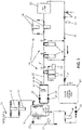
- Fig. 1 shows schematically and simplified a structural diagram of a water treatment system scheme directed to water reusage according to an embodiment.
- a water treatment system includes a raw water tank 10 connected to a water supply 15 supplying tap or raw water to the system, a reverse osmosis plant or unit 20 arranged to produce purified water from water supplied from the raw water tank 10 via a raw water supply line 25, at least one water treatment facility 60 alongside the raw water supply line 25 downstream the raw water tank 10 and upstream the reverse osmosis plant 20, and a reuse water feedback line 35 arranged to feed grey water collected from the reverse osmosis plant 20 and/or the at least one water treatment facility 60 back to the raw water tank 10 for reuse.
- grey water collected from the reverse osmosis plant 20 and/or the at least one water treatment facility 60 is fed back to the raw water tank 10 for reuse.
- At least one first pump 26 is provided in the raw water supply line 25 downstream of the raw water tank 10 and arranged to convey a required amount of raw water out of the raw water tank 10 through the raw water supply line 25 toward the reverse osmosis plant 20. It may be preferable that two pumps 26 are provided in parallel pump mounting branches of the raw water supply line 25, and that a pressure vessel 27 is installed in at least one of the parallel pump mounting branches.
- a second pump 36 is provided in the reuse water feedback line 35 downstream a water saving storage tank 40 and arranged to convey a required amount of waste and/or grey water stored in the water saving storage tank 40 out of the water saving storage tank 40 toward the raw water tank 10.
- a predetermined number of pressure gauges 28, respectively indicated by round circles filled white along the fluid paths in Fig. 1 may be distributed in the water treatment system at respective predetermined locations in order to detect fluid pressure where required.
- a predetermined number of manually and/or automatically controllable isolation valves 29, respectively indicated by solid black double triangles facing each other in Fig. 1 , and check valves 24, respectively indicated by solid black single bar triangles in Fig. 1 may be arranged in the water treatment system at respective predetermined locations in the fluid paths in order to allow for opening and closing a fluid path where required, or to prevent fluid from flowing back behind a predetermined position (the position of the check valve 24), and thus to control and direct, and allow or prevent fluid (water) flow, as required.
- a predetermined configuration of isolation valves 29 are provided at connection points of the at least one water treatment facility 60 along the raw water supply line 25 in such a manner that the raw water supply line 25 may be closed, or at least partially closed, between an input to a water treatment facility 60 and an output thereof so as to force all or part of the raw water flowing toward the reverse osmosis plant 20 to enter into the water treatment facility.
- the isolation valve 29 configuration can also be set to prevent fluid from entering into the water treatment facility so as to completely bypass the same, for example when its function is not needed or when some maintenance is required.
- isolation valve 29 configuration at device entry or fluid path branch points may be arranged to operate as a controllable multiway valve adapted to selectably connect or disconnect multiple fluid paths.
- the water treatment system according to the embodiment is provided with a predetermined number of fluid drains, indicated by an arrow and sink symbol in Fig. 1 , which mainly serve to finally drain any surplus or overflowing fluid and water, e.g. to send waste water to drain, respectively, a predetermined number of sample points 21, indicated by smaller double triangles facing each other in Fig. 1 , and conductivity probe points 22 provided to allow for probing or sampling the process fluid where necessary, a predetermined number of solenoid valves 23 arranged for enhanced fluid control.
- a predetermined number of fluid drains indicated by an arrow and sink symbol in Fig. 1 , which mainly serve to finally drain any surplus or overflowing fluid and water, e.g. to send waste water to drain, respectively, a predetermined number of sample points 21, indicated by smaller double triangles facing each other in Fig. 1 , and conductivity probe points 22 provided to allow for probing or sampling the process fluid where necessary, a predetermined number of solenoid valves 23 arranged for enhanced fluid control.
- the water treatment system according to the embodiment may be virtually subdivided in two sections.
- a first section shown by solid lines in Fig. 1 , may represent the raw or tap water supply from water supply 15 via the raw water tank 10 and the raw water supply line 25 and, as the case may be, the at least one water treatment facility (or unit, device or station) 60 to the reverse osmosis plant 20.
- a second section shown by dashed lines in Fig.
- a strainer 37 may be inserted into the reuse water feedback line 35 upstream the water saving storage tank 40.
- At least one water treatment facility 60 includes for example a duplex water softening plant 62, two activated carbon filters 64 with backwash facility and two sand filters 66.
- Each of these facilities, or devices, is connectable to the raw water supply line 25 via a respective set of isolation valves 29 as mentioned above, allowing raw water to enter into each of the water treatment facility and to leave the water treatment facility after treatment thereat.
- the duplex water softening plant 62 is arranged to operate with NaCl brine from a solute reservoir 63.
- the NaCl brine may be prepared in situ using NaCl pellets, or be otherwise filled into the solute reservoir 63.
- the present embodiment features the use of grey water, or a certain amount of grey water, fed back from the reverse osmosis drain to regenerate the softener.
- the achieved effect is significant because the softener (an ion exchanger) uses NaCl brine to remove Ca and Mg from the tap water.
- the softened water has already a higher load of Na which will be concentrated even higher by the reverse osmosis. This concentrate can be used for creating NaCl brine for regeneration. When doing so there is also a potential of saving a certain amount of NaCl pellets, and accordingly, not only water but also NaCl can advantageously be saved.
- the present embodiment features collecting water from the wash back cycle of the carbon filters.
- Carbon filters are used to adsorb chlorine and other ions, and consist of an active filter granulate that needs backwashing in order to loosen the granulate structure.
- the water used for backwashing the carbon filters is not overloaded with additional substances and, thus, reusable, and this water is therefore filtered and sent back to the raw water tank 10.
- only the activated carbon filters with backwash facility are connected to the reuse water feedback line 35 in order to collect the backwash water.
- one or more sand filters 66 are arranged and provided in a backwashable manner upstream the reverse osmosis plant 20 as a final water filter arranged to filter out particle sizes of 5 ⁇ m or more absolute.
- Sand filters are designed to filter out physical contaminations from the tap water and need to be backwashed on a regular basis to flush out any contaminations and to loosen the sand bed.
- the reused water can be used for the filter flushing process.
- the water saving storage tank 40 is arranged as a waste water (e.g. from the reverse osmosis plant 20) and grey water (e.g. from the reverse osmosis plant and/or the carbon filters 64) buffer in the reuse water feedback line 35, and the reuse water feedback line is arranged to feed the waste water and/or grey water collected from said reverse osmosis plant 20 and the at least one water treatment facility 60 into the water saving storage tank 40.
- a waste water e.g. from the reverse osmosis plant 20
- grey water e.g. from the reverse osmosis plant and/or the carbon filters 64
- a reuse water filter 44 arranged to e.g. filter particle sizes of 5 ⁇ m or more is arranged in the reuse water feedback line 35 downstream the water saving storage tank 40.
- the water treatment system according to the present embodiment can be equipped with at least one backwashable raw water filter 12 arranged to filter out particle sizes of 20 ⁇ m or more.
- This raw water filter 12 can be placed upstream the raw water tank 10.
- the raw water tank 10 may be equipped with a high fluid level detector and a low fluid level detector arranged at and connected to the reuse water feedback line 35 that feeds the reusable water into the raw water tank 10, and further equipped with a high fluid level detector and a low fluid level detector arranged at and connected to the raw water supply line feeding raw water into the raw water tank 10.
- These detectors which may also be sensors, switches and the like, may be configured to output detection signals to be used in e.g. a raw water pump 26 and/or reuse water pump 36 control, and/or inlet valve control. Providing two separate detector circuits is advantageous in that respective control may be carried out independently.
- the system and the method according to the present invention allow for the reuse of a significant volume of water which is hitherto sent to drain, and therefore achieves a significant ecological and financial benefit through the reuse of this water.
- a significant reduction of NaCl consumption is achieved because a remarkable percentage of NaCl is reused.
Landscapes
- Chemical & Material Sciences (AREA)
- Water Supply & Treatment (AREA)
- Engineering & Computer Science (AREA)
- Organic Chemistry (AREA)
- Environmental & Geological Engineering (AREA)
- Hydrology & Water Resources (AREA)
- Life Sciences & Earth Sciences (AREA)
- Chemical Kinetics & Catalysis (AREA)
- Nanotechnology (AREA)
- Analytical Chemistry (AREA)
- Inorganic Chemistry (AREA)
- Separation Using Semi-Permeable Membranes (AREA)
- Water Treatment By Sorption (AREA)
- Treatment Of Water By Ion Exchange (AREA)
- Filtration Of Liquid (AREA)
Claims (6)
- Verfahren zur Wasseraufbereitung unter Verwendung eines Wasseraufbereitungssystems mit:einem Rohwassertank (10), der mit einer Wasserzufuhr (15) verbunden ist;eine Umkehrosmoseeinheit (20), die so angeordnet ist, um gereinigtes Wasser aus dem Wassereinlass des Rohwassertanks (10) über eine Rohwasserversorgungsleitung (25) zu erzeugen;mindestens eine Wasseraufbereitungsanlage (60) entlang der Rohwasserversorgungsleitung (25) stromabwärts des Rohwassertanks (10) und stromaufwärts der Umkehrosmoseeinheit (20), wobei die mindestens eine Wasseraufbereitungsanlage (60) ein Aktivkohlefilter (64) mit einer Rückspüleinrichtung und optional weiteren Wasseraufbereitungsanlagen ist, nämlich einer Wasserenthärtungsanlage (62, 63) und/oder einem Sandfilter (66), und wobei die mindestens eine Wasseraufbereitungsanlage (60) so konfiguriert ist, um mit der Rohwasserversorgungsleitung (25) über einen Satz von Absperrventilen (29) verbindbar zu sein, die es dem Rohwasser ermöglichen, in die Wasseraufbereitungsanlage (60) einzutreten und aus der Wasseraufbereitungsanlage (60) auszutreten; undeine Wasserrücklaufleitung zur Wiederverwendung (35), die so angeordnet ist, um das von der Umkehrosmoseeinheit (20) und dem Aktivkohlefilter (64) gesammelte Abwasser zum Rohwassertank (10) zur Wiederverwendung zurückzuführen, wobei der wassersparende Speichertank (40) als Abwasserpuffer in der Wasserrücklaufleitung zur Wiederverwendung (35) angeordnet ist, mit den folgenden Schritten:Sammeln des Wassers, das für die Rückspülung von Kohle aus dem Aktivkohlefilter (64) verwendet wird, in dem wassersparenden Speichertank (40),Filtern und Zurückführen des durch die Filter (44) gesammelten Wassers in den Rohwassertank (10) gemäß einem Bedarf zur Wiederverwendung, unddas Abwasser aus der Umkehrosmoseanlage (20) auf Konzentration zu überwachen und, wenn die Konzentration unter einem Sollwert liegt, zur Wiederverwendung entlang des Kohle-Rückspülwassers in den wassersparenden Speichertank (40) zu leiten.
- Verfahren zur Wasseraufbereitung nach Anspruch 1, wobei in einem Fall, in dem eine Wasserenthärtungsanlage (62, 63) verwendet wird, die Wasserenthärtungsanlage (62, 63) mit einer NaCI-Sole (63) betrieben wird.
- Verfahren zur Wasseraufbereitung nach Anspruch 1 oder 2, wobei die Filter (44) zum Filtern von Partikelgrößen von 5 mm oder mehr verwendet werden und in der Wasserrücklaufleitung zur Wiederverwendung (35) stromabwärts des wassersparenden Speichertanks (40) angeordnet sind.
- Verfahren zur Wasseraufbereitung nach einem der vorhergehenden Ansprüche, wobei in dem Fall, in dem der mindestens eine Sandfilter (66) als zusätzliche Wasseraufbereitungsanlage zum Filtern von Partikelgrößen von 5 mm oder mehr absolut verwendet wird, der mindestens eine Sandfilter (66) stromabwärts von der mindestens einen Wasseraufbereitungsanlage (60) und stromaufwärts von der Umkehrosmoseeinheit (20) in einer rückspülbaren Weise angeordnet ist.
- Verfahren zur Wasseraufbereitung nach einem der vorhergehenden Ansprüche, wobei mindestens ein Rohwasserfilter (12) verwendet wird, um Partikelgrößen von 20 mm oder mehr zu filtern, und wobei der mindestens eine Rohwasserfilter (12) in einer rückspülbaren Weise stromaufwärts von dem Rohwassertank (10) angeordnet ist.
- Verfahren zur Wasseraufbereitung nach einem der vorhergehenden Ansprüche, wobei:mindestens eine Rohwasserpumpe (26) und ein Druckbehälter (27) in der Rohwasserzuleitung (25) stromabwärts von dem Rohwassertank (10) und stromaufwärts von der mindestens einen Wasseraufbereitungsanlage (60) verwendet werden;mindestens eine Wasserpumpe zur Wiederverwendung (36) und ein Sieb (37) in der Wasserrücklaufleitung zur Wiederverwendung (35) verwendet werden;und ein Hochpegeldetektor und ein Niedrigpegeldetektor verwendet werden, die an der Wasserrücklaufleitung zur Wiederverwendung (35), die das Wasser zur Wiederverwendung in den Rohwassertank (10) leitet, angeordnet und mit dieser verbunden sind, und ein Hochpegeldetektor und ein Niedrigpegeldetektor verwendet werden, die an der Rohwasserzuleitung, die das Rohwasser in den Rohwassertank (10) leitet, angeordnet und mit dieser verbunden sind, wobei die Detektoren, die Detektionssignale erzeugen, in mindestens einer Steuerung für die Rohwasserpumpe (26) und die Wasserpumpe zur Wiederverwendung (36) verwendet werden.
Priority Applications (5)
| Application Number | Priority Date | Filing Date | Title |
|---|---|---|---|
| EP17159395.7A EP3372302B1 (de) | 2017-03-06 | 2017-03-06 | Wasserbehandlungsverfahren |
| US15/896,181 US10399870B2 (en) | 2017-03-06 | 2018-02-14 | Water treatment system |
| CN201820293810.4U CN208586137U (zh) | 2017-03-06 | 2018-03-02 | 水处理系统 |
| CN201810174617.3A CN108529783A (zh) | 2017-03-06 | 2018-03-02 | 水处理系统 |
| JP2018039328A JP7093202B2 (ja) | 2017-03-06 | 2018-03-06 | 水処理システム |
Applications Claiming Priority (1)
| Application Number | Priority Date | Filing Date | Title |
|---|---|---|---|
| EP17159395.7A EP3372302B1 (de) | 2017-03-06 | 2017-03-06 | Wasserbehandlungsverfahren |
Publications (2)
| Publication Number | Publication Date |
|---|---|
| EP3372302A1 EP3372302A1 (de) | 2018-09-12 |
| EP3372302B1 true EP3372302B1 (de) | 2022-12-21 |
Family
ID=58231525
Family Applications (1)
| Application Number | Title | Priority Date | Filing Date |
|---|---|---|---|
| EP17159395.7A Active EP3372302B1 (de) | 2017-03-06 | 2017-03-06 | Wasserbehandlungsverfahren |
Country Status (4)
| Country | Link |
|---|---|
| US (1) | US10399870B2 (de) |
| EP (1) | EP3372302B1 (de) |
| JP (1) | JP7093202B2 (de) |
| CN (2) | CN208586137U (de) |
Families Citing this family (11)
| Publication number | Priority date | Publication date | Assignee | Title |
|---|---|---|---|---|
| RU2606986C2 (ru) | 2014-10-27 | 2017-01-10 | Закрытое Акционерное Общество "Аквафор Продакшн" (Зао "Аквафор Продакшн") | Система очистки жидкости |
| RU2686199C1 (ru) * | 2018-09-27 | 2019-04-24 | Общество С Ограниченной Ответственностью "Аквафор" (Ооо "Аквафор") | Система очистки жидкости |
| JP7466999B2 (ja) * | 2020-07-06 | 2024-04-15 | 株式会社ディスコ | 純水生成装置 |
| CN112144765B (zh) * | 2020-09-28 | 2021-10-15 | 上海交通大学 | 一种海绵城市建设用绿色屋顶及雨水净化耦合系统 |
| CN112209529A (zh) * | 2020-10-21 | 2021-01-12 | 宝利化(南京)制药有限公司 | 一种可在线监测纯化水的制水系统 |
| DE102021104525A1 (de) * | 2021-02-25 | 2022-08-25 | Markus Pfander | Wasseraufbereitungsanlage, insbesondere für Trinkwasser |
| DE202021100938U1 (de) * | 2021-02-25 | 2022-05-30 | Markus Pfander | Sicherungseinrichtung zum Schutz von Trinkwasser gegen Verschmutzung durch Rückfließen |
| PE20241455A1 (es) | 2021-09-24 | 2024-07-15 | Bechtel Energy Tech And Solutions Inc | Sistema de desalinizacion de eyector de baja energia |
| US20230416116A1 (en) * | 2022-06-22 | 2023-12-28 | Caron Products And Services, Inc. | System for conditioning water quality |
| CH721801A2 (de) | 2024-05-07 | 2025-11-14 | Lauer AG | Vorrichtung und Verfahren zur Herstellung von Reinwasser mit hohen Qualitätsanforderungen wie beispielsweise Reinwasser für pharmazeutische Anwendungen |
| CN120081454B (zh) * | 2025-04-29 | 2025-10-28 | 惠州市神泉科技净水设备制造有限公司 | 一种用于净化水质的活性炭渗透滤芯及净化方法 |
Family Cites Families (18)
| Publication number | Priority date | Publication date | Assignee | Title |
|---|---|---|---|---|
| JP2995710B2 (ja) | 1993-09-19 | 1999-12-27 | 難波プレス工業株式会社 | 座り心地良好なクッション体構造 |
| EP0676374A3 (de) | 1994-04-08 | 1996-03-27 | Guenter Lauer | Verfahren und Vorrichtung zur Reinwasserherstellung. |
| US5451314A (en) * | 1994-04-09 | 1995-09-19 | Neuenschwander; Peter | Plant for the treatment of drinking water from raw water |
| JPH11244852A (ja) * | 1998-02-26 | 1999-09-14 | Japan Organo Co Ltd | 淡水化装置及び該淡水化装置で用いられるろ過装置の逆洗方法 |
| JP2000126767A (ja) * | 1998-10-21 | 2000-05-09 | Toray Ind Inc | 精製水の製造方法および装置 |
| JP2001026767A (ja) | 1999-07-16 | 2001-01-30 | Toyota Motor Corp | 湿式摩擦材及びその製造方法 |
| EP1242313B1 (de) * | 1999-10-27 | 2010-01-06 | NUKEM Technologies GmbH | Anlage zur behandlung von abwasser |
| US7132052B2 (en) * | 2003-12-11 | 2006-11-07 | General Electric Company | System for the purification and reuse of spent brine in a water softener |
| US7815804B2 (en) * | 2006-12-12 | 2010-10-19 | Otv Sa S.A. | Method for treating wastewater or produced water |
| CN201873580U (zh) * | 2010-08-23 | 2011-06-22 | 西安华新能源工程有限公司 | 一种用于硅铁余热发电锅炉的补给水处理系统 |
| JP2012217975A (ja) * | 2011-04-13 | 2012-11-12 | Eco Life:Kk | 水処理システム |
| JP5879901B2 (ja) * | 2011-10-13 | 2016-03-08 | 栗田工業株式会社 | 有機排水の回収処理装置及び回収処理方法 |
| GB2500685A (en) * | 2012-03-30 | 2013-10-02 | Spirax Sarco Ltd | Steam plant with reverse osmosis unit |
| CN103880217A (zh) * | 2014-03-25 | 2014-06-25 | 济钢集团有限公司 | 一种软水制备系统排水的回收利用模型及回收利用方法 |
| JP6428017B2 (ja) * | 2014-07-23 | 2018-11-28 | 栗田工業株式会社 | 水処理装置及び水処理設備の洗浄方法 |
| JP6467911B2 (ja) * | 2014-12-26 | 2019-02-13 | 三浦工業株式会社 | 水処理システム |
| JP2017012985A (ja) * | 2015-06-30 | 2017-01-19 | 株式会社日立製作所 | 水処理システム及び水処理方法 |
| CN105347539A (zh) * | 2015-12-15 | 2016-02-24 | 苏州依斯倍环保装备科技有限公司 | 集成自动化的工业废水中水回用装置 |
-
2017
- 2017-03-06 EP EP17159395.7A patent/EP3372302B1/de active Active
-
2018
- 2018-02-14 US US15/896,181 patent/US10399870B2/en active Active
- 2018-03-02 CN CN201820293810.4U patent/CN208586137U/zh active Active
- 2018-03-02 CN CN201810174617.3A patent/CN108529783A/zh active Pending
- 2018-03-06 JP JP2018039328A patent/JP7093202B2/ja active Active
Also Published As
| Publication number | Publication date |
|---|---|
| CN208586137U (zh) | 2019-03-08 |
| JP2018144032A (ja) | 2018-09-20 |
| US10399870B2 (en) | 2019-09-03 |
| JP7093202B2 (ja) | 2022-06-29 |
| US20180251385A1 (en) | 2018-09-06 |
| CN108529783A (zh) | 2018-09-14 |
| EP3372302A1 (de) | 2018-09-12 |
Similar Documents
| Publication | Publication Date | Title |
|---|---|---|
| EP3372302B1 (de) | Wasserbehandlungsverfahren | |
| US9199866B2 (en) | High recovery drinking water process | |
| Kabay et al. | Adsorption-membrane filtration (AMF) hybrid process for boron removal from seawater: an overview | |
| CN105392552B (zh) | 含硼水的处理方法和装置 | |
| KR20110007180A (ko) | 역침투막 모듈의 운전방법 | |
| CN102942265A (zh) | 全膜法水处理一体化装置 | |
| KR20130011174A (ko) | 정제수제조시스템 역삼투압 장치 농축수의 재활용시스템 및 그 방법 | |
| Wong et al. | A pilot study on a membrane process for the treatment and recycling of spent final rinse water from electroless plating | |
| JP6344114B2 (ja) | 水処理装置及び水処理設備の洗浄方法 | |
| KR101504545B1 (ko) | 수질 변화에 대응 가능한 종합 정수 처리 장치 및 방법 | |
| JP2012225755A (ja) | 放射性汚染水処理システムおよび艀型放射性汚染水処理施設ならびに放射性汚染水処理方法および艀上放射性汚染水処理方法 | |
| CN210030227U (zh) | 化学镀镍漂洗废水的浓缩处理装置 | |
| CN110540318A (zh) | 一种污水回收处理系统及处理工艺 | |
| JP5962135B2 (ja) | 超純水製造装置 | |
| Tao et al. | RO brine treatment and recovery by biological activated carbon and capacitive deionization process | |
| Im et al. | Possibility assessment of ultrafiltration membrane pre-treatment efficiency for brackish water reverse osmosis-based wastewater reuse: Lab and demonstration | |
| Suárez et al. | One-year operational experience with ultrafiltration as pretreatment of seawater reverse osmosis desalination system (Maspalomas-I Plant) | |
| JP2003117552A (ja) | 淡水化装置 | |
| Gibert et al. | Composition and reversibility of fouling on low-pressure membranes in the filtration of coagulated water: insights into organic fractions behaviour | |
| JP7819283B1 (ja) | 純水製造システムおよび純水製造方法 | |
| Amouamouha et al. | Performance investigation and cost evaluation of nanofiltration membranes in groundwater remediation | |
| JP7568009B2 (ja) | 水処理システム及び水処理方法 | |
| CN205347543U (zh) | 一种镍回收循环装置 | |
| CN121107662B (zh) | 一种用于电解水制氢的集装箱式水预处理bop系统 | |
| KR101443909B1 (ko) | 역삼투 정수장치 |
Legal Events
| Date | Code | Title | Description |
|---|---|---|---|
| PUAI | Public reference made under article 153(3) epc to a published international application that has entered the european phase |
Free format text: ORIGINAL CODE: 0009012 |
|
| STAA | Information on the status of an ep patent application or granted ep patent |
Free format text: STATUS: THE APPLICATION HAS BEEN PUBLISHED |
|
| AK | Designated contracting states |
Kind code of ref document: A1 Designated state(s): AL AT BE BG CH CY CZ DE DK EE ES FI FR GB GR HR HU IE IS IT LI LT LU LV MC MK MT NL NO PL PT RO RS SE SI SK SM TR |
|
| AX | Request for extension of the european patent |
Extension state: BA ME |
|
| STAA | Information on the status of an ep patent application or granted ep patent |
Free format text: STATUS: REQUEST FOR EXAMINATION WAS MADE |
|
| 17P | Request for examination filed |
Effective date: 20190415 |
|
| STAA | Information on the status of an ep patent application or granted ep patent |
Free format text: STATUS: EXAMINATION IS IN PROGRESS |
|
| 17Q | First examination report despatched |
Effective date: 20200416 |
|
| GRAP | Despatch of communication of intention to grant a patent |
Free format text: ORIGINAL CODE: EPIDOSNIGR1 |
|
| STAA | Information on the status of an ep patent application or granted ep patent |
Free format text: STATUS: GRANT OF PATENT IS INTENDED |
|
| RIC1 | Information provided on ipc code assigned before grant |
Ipc: C02F 1/28 20060101ALI20220623BHEP Ipc: C02F 1/00 20060101ALI20220623BHEP Ipc: B01D 15/20 20060101ALI20220623BHEP Ipc: C02F 1/44 20060101ALI20220623BHEP Ipc: C02F 1/42 20060101ALI20220623BHEP Ipc: B01D 61/10 20060101ALI20220623BHEP Ipc: B01D 61/04 20060101ALI20220623BHEP Ipc: B01D 61/02 20060101AFI20220623BHEP |
|
| INTG | Intention to grant announced |
Effective date: 20220708 |
|
| GRAS | Grant fee paid |
Free format text: ORIGINAL CODE: EPIDOSNIGR3 |
|
| GRAA | (expected) grant |
Free format text: ORIGINAL CODE: 0009210 |
|
| STAA | Information on the status of an ep patent application or granted ep patent |
Free format text: STATUS: THE PATENT HAS BEEN GRANTED |
|
| AK | Designated contracting states |
Kind code of ref document: B1 Designated state(s): AL AT BE BG CH CY CZ DE DK EE ES FI FR GB GR HR HU IE IS IT LI LT LU LV MC MK MT NL NO PL PT RO RS SE SI SK SM TR |
|
| REG | Reference to a national code |
Ref country code: GB Ref legal event code: FG4D |
|
| REG | Reference to a national code |
Ref country code: DE Ref legal event code: R096 Ref document number: 602017064726 Country of ref document: DE |
|
| REG | Reference to a national code |
Ref country code: CH Ref legal event code: EP |
|
| REG | Reference to a national code |
Ref country code: AT Ref legal event code: REF Ref document number: 1538710 Country of ref document: AT Kind code of ref document: T Effective date: 20230115 |
|
| REG | Reference to a national code |
Ref country code: IE Ref legal event code: FG4D |
|
| REG | Reference to a national code |
Ref country code: SE Ref legal event code: TRGR |
|
| REG | Reference to a national code |
Ref country code: LT Ref legal event code: MG9D |
|
| REG | Reference to a national code |
Ref country code: NL Ref legal event code: MP Effective date: 20221221 |
|
| PG25 | Lapsed in a contracting state [announced via postgrant information from national office to epo] |
Ref country code: NO Free format text: LAPSE BECAUSE OF FAILURE TO SUBMIT A TRANSLATION OF THE DESCRIPTION OR TO PAY THE FEE WITHIN THE PRESCRIBED TIME-LIMIT Effective date: 20230321 Ref country code: LT Free format text: LAPSE BECAUSE OF FAILURE TO SUBMIT A TRANSLATION OF THE DESCRIPTION OR TO PAY THE FEE WITHIN THE PRESCRIBED TIME-LIMIT Effective date: 20221221 Ref country code: FI Free format text: LAPSE BECAUSE OF FAILURE TO SUBMIT A TRANSLATION OF THE DESCRIPTION OR TO PAY THE FEE WITHIN THE PRESCRIBED TIME-LIMIT Effective date: 20221221 |
|
| REG | Reference to a national code |
Ref country code: AT Ref legal event code: MK05 Ref document number: 1538710 Country of ref document: AT Kind code of ref document: T Effective date: 20221221 |
|
| PG25 | Lapsed in a contracting state [announced via postgrant information from national office to epo] |
Ref country code: RS Free format text: LAPSE BECAUSE OF FAILURE TO SUBMIT A TRANSLATION OF THE DESCRIPTION OR TO PAY THE FEE WITHIN THE PRESCRIBED TIME-LIMIT Effective date: 20221221 Ref country code: LV Free format text: LAPSE BECAUSE OF FAILURE TO SUBMIT A TRANSLATION OF THE DESCRIPTION OR TO PAY THE FEE WITHIN THE PRESCRIBED TIME-LIMIT Effective date: 20221221 Ref country code: HR Free format text: LAPSE BECAUSE OF FAILURE TO SUBMIT A TRANSLATION OF THE DESCRIPTION OR TO PAY THE FEE WITHIN THE PRESCRIBED TIME-LIMIT Effective date: 20221221 Ref country code: GR Free format text: LAPSE BECAUSE OF FAILURE TO SUBMIT A TRANSLATION OF THE DESCRIPTION OR TO PAY THE FEE WITHIN THE PRESCRIBED TIME-LIMIT Effective date: 20230322 |
|
| PG25 | Lapsed in a contracting state [announced via postgrant information from national office to epo] |
Ref country code: NL Free format text: LAPSE BECAUSE OF FAILURE TO SUBMIT A TRANSLATION OF THE DESCRIPTION OR TO PAY THE FEE WITHIN THE PRESCRIBED TIME-LIMIT Effective date: 20221221 |
|
| PG25 | Lapsed in a contracting state [announced via postgrant information from national office to epo] |
Ref country code: SM Free format text: LAPSE BECAUSE OF FAILURE TO SUBMIT A TRANSLATION OF THE DESCRIPTION OR TO PAY THE FEE WITHIN THE PRESCRIBED TIME-LIMIT Effective date: 20221221 Ref country code: RO Free format text: LAPSE BECAUSE OF FAILURE TO SUBMIT A TRANSLATION OF THE DESCRIPTION OR TO PAY THE FEE WITHIN THE PRESCRIBED TIME-LIMIT Effective date: 20221221 Ref country code: PT Free format text: LAPSE BECAUSE OF FAILURE TO SUBMIT A TRANSLATION OF THE DESCRIPTION OR TO PAY THE FEE WITHIN THE PRESCRIBED TIME-LIMIT Effective date: 20230421 Ref country code: ES Free format text: LAPSE BECAUSE OF FAILURE TO SUBMIT A TRANSLATION OF THE DESCRIPTION OR TO PAY THE FEE WITHIN THE PRESCRIBED TIME-LIMIT Effective date: 20221221 Ref country code: EE Free format text: LAPSE BECAUSE OF FAILURE TO SUBMIT A TRANSLATION OF THE DESCRIPTION OR TO PAY THE FEE WITHIN THE PRESCRIBED TIME-LIMIT Effective date: 20221221 Ref country code: CZ Free format text: LAPSE BECAUSE OF FAILURE TO SUBMIT A TRANSLATION OF THE DESCRIPTION OR TO PAY THE FEE WITHIN THE PRESCRIBED TIME-LIMIT Effective date: 20221221 Ref country code: AT Free format text: LAPSE BECAUSE OF FAILURE TO SUBMIT A TRANSLATION OF THE DESCRIPTION OR TO PAY THE FEE WITHIN THE PRESCRIBED TIME-LIMIT Effective date: 20221221 |
|
| PG25 | Lapsed in a contracting state [announced via postgrant information from national office to epo] |
Ref country code: SK Free format text: LAPSE BECAUSE OF FAILURE TO SUBMIT A TRANSLATION OF THE DESCRIPTION OR TO PAY THE FEE WITHIN THE PRESCRIBED TIME-LIMIT Effective date: 20221221 Ref country code: PL Free format text: LAPSE BECAUSE OF FAILURE TO SUBMIT A TRANSLATION OF THE DESCRIPTION OR TO PAY THE FEE WITHIN THE PRESCRIBED TIME-LIMIT Effective date: 20221221 Ref country code: IS Free format text: LAPSE BECAUSE OF FAILURE TO SUBMIT A TRANSLATION OF THE DESCRIPTION OR TO PAY THE FEE WITHIN THE PRESCRIBED TIME-LIMIT Effective date: 20230421 Ref country code: AL Free format text: LAPSE BECAUSE OF FAILURE TO SUBMIT A TRANSLATION OF THE DESCRIPTION OR TO PAY THE FEE WITHIN THE PRESCRIBED TIME-LIMIT Effective date: 20221221 |
|
| REG | Reference to a national code |
Ref country code: DE Ref legal event code: R097 Ref document number: 602017064726 Country of ref document: DE |
|
| PLBE | No opposition filed within time limit |
Free format text: ORIGINAL CODE: 0009261 |
|
| STAA | Information on the status of an ep patent application or granted ep patent |
Free format text: STATUS: NO OPPOSITION FILED WITHIN TIME LIMIT |
|
| PG25 | Lapsed in a contracting state [announced via postgrant information from national office to epo] |
Ref country code: MC Free format text: LAPSE BECAUSE OF FAILURE TO SUBMIT A TRANSLATION OF THE DESCRIPTION OR TO PAY THE FEE WITHIN THE PRESCRIBED TIME-LIMIT Effective date: 20221221 Ref country code: DK Free format text: LAPSE BECAUSE OF FAILURE TO SUBMIT A TRANSLATION OF THE DESCRIPTION OR TO PAY THE FEE WITHIN THE PRESCRIBED TIME-LIMIT Effective date: 20221221 |
|
| P01 | Opt-out of the competence of the unified patent court (upc) registered |
Effective date: 20231012 |
|
| 26N | No opposition filed |
Effective date: 20230922 |
|
| REG | Reference to a national code |
Ref country code: BE Ref legal event code: MM Effective date: 20230331 |
|
| PG25 | Lapsed in a contracting state [announced via postgrant information from national office to epo] |
Ref country code: LU Free format text: LAPSE BECAUSE OF NON-PAYMENT OF DUE FEES Effective date: 20230306 |
|
| REG | Reference to a national code |
Ref country code: IE Ref legal event code: MM4A |
|
| PG25 | Lapsed in a contracting state [announced via postgrant information from national office to epo] |
Ref country code: SI Free format text: LAPSE BECAUSE OF FAILURE TO SUBMIT A TRANSLATION OF THE DESCRIPTION OR TO PAY THE FEE WITHIN THE PRESCRIBED TIME-LIMIT Effective date: 20221221 Ref country code: IE Free format text: LAPSE BECAUSE OF NON-PAYMENT OF DUE FEES Effective date: 20230306 |
|
| PG25 | Lapsed in a contracting state [announced via postgrant information from national office to epo] |
Ref country code: BE Free format text: LAPSE BECAUSE OF NON-PAYMENT OF DUE FEES Effective date: 20230331 |
|
| PG25 | Lapsed in a contracting state [announced via postgrant information from national office to epo] |
Ref country code: BG Free format text: LAPSE BECAUSE OF FAILURE TO SUBMIT A TRANSLATION OF THE DESCRIPTION OR TO PAY THE FEE WITHIN THE PRESCRIBED TIME-LIMIT Effective date: 20221221 |
|
| PG25 | Lapsed in a contracting state [announced via postgrant information from national office to epo] |
Ref country code: BG Free format text: LAPSE BECAUSE OF FAILURE TO SUBMIT A TRANSLATION OF THE DESCRIPTION OR TO PAY THE FEE WITHIN THE PRESCRIBED TIME-LIMIT Effective date: 20221221 |
|
| PGFP | Annual fee paid to national office [announced via postgrant information from national office to epo] |
Ref country code: SE Payment date: 20250311 Year of fee payment: 9 |
|
| PGFP | Annual fee paid to national office [announced via postgrant information from national office to epo] |
Ref country code: DE Payment date: 20250319 Year of fee payment: 9 |
|
| PGFP | Annual fee paid to national office [announced via postgrant information from national office to epo] |
Ref country code: FR Payment date: 20250324 Year of fee payment: 9 |
|
| PGFP | Annual fee paid to national office [announced via postgrant information from national office to epo] |
Ref country code: GB Payment date: 20250324 Year of fee payment: 9 |
|
| PGFP | Annual fee paid to national office [announced via postgrant information from national office to epo] |
Ref country code: IT Payment date: 20250331 Year of fee payment: 9 |
|
| PGFP | Annual fee paid to national office [announced via postgrant information from national office to epo] |
Ref country code: CH Payment date: 20250401 Year of fee payment: 9 |
|
| PG25 | Lapsed in a contracting state [announced via postgrant information from national office to epo] |
Ref country code: CY Free format text: LAPSE BECAUSE OF FAILURE TO SUBMIT A TRANSLATION OF THE DESCRIPTION OR TO PAY THE FEE WITHIN THE PRESCRIBED TIME-LIMIT; INVALID AB INITIO Effective date: 20170306 |
|
| PG25 | Lapsed in a contracting state [announced via postgrant information from national office to epo] |
Ref country code: HU Free format text: LAPSE BECAUSE OF FAILURE TO SUBMIT A TRANSLATION OF THE DESCRIPTION OR TO PAY THE FEE WITHIN THE PRESCRIBED TIME-LIMIT; INVALID AB INITIO Effective date: 20170306 |
|
| PG25 | Lapsed in a contracting state [announced via postgrant information from national office to epo] |
Ref country code: TR Free format text: LAPSE BECAUSE OF FAILURE TO SUBMIT A TRANSLATION OF THE DESCRIPTION OR TO PAY THE FEE WITHIN THE PRESCRIBED TIME-LIMIT Effective date: 20221221 |