EP3372176A1 - Instrument médical - Google Patents
Instrument médical Download PDFInfo
- Publication number
- EP3372176A1 EP3372176A1 EP18160451.3A EP18160451A EP3372176A1 EP 3372176 A1 EP3372176 A1 EP 3372176A1 EP 18160451 A EP18160451 A EP 18160451A EP 3372176 A1 EP3372176 A1 EP 3372176A1
- Authority
- EP
- European Patent Office
- Prior art keywords
- guide
- latching
- medical instrument
- handle
- locking
- Prior art date
- Legal status (The legal status is an assumption and is not a legal conclusion. Google has not performed a legal analysis and makes no representation as to the accuracy of the status listed.)
- Granted
Links
Images


Classifications
-
- A—HUMAN NECESSITIES
- A61—MEDICAL OR VETERINARY SCIENCE; HYGIENE
- A61B—DIAGNOSIS; SURGERY; IDENTIFICATION
- A61B17/00—Surgical instruments, devices or methods, e.g. tourniquets
- A61B17/04—Surgical instruments, devices or methods, e.g. tourniquets for suturing wounds; Holders or packages for needles or suture materials
- A61B17/0483—Hand-held instruments for holding sutures
-
- A—HUMAN NECESSITIES
- A61—MEDICAL OR VETERINARY SCIENCE; HYGIENE
- A61B—DIAGNOSIS; SURGERY; IDENTIFICATION
- A61B17/00—Surgical instruments, devices or methods, e.g. tourniquets
- A61B17/34—Trocars; Puncturing needles
- A61B17/3403—Needle locating or guiding means
-
- A—HUMAN NECESSITIES
- A61—MEDICAL OR VETERINARY SCIENCE; HYGIENE
- A61B—DIAGNOSIS; SURGERY; IDENTIFICATION
- A61B17/00—Surgical instruments, devices or methods, e.g. tourniquets
- A61B17/04—Surgical instruments, devices or methods, e.g. tourniquets for suturing wounds; Holders or packages for needles or suture materials
- A61B17/06—Needles ; Sutures; Needle-suture combinations; Holders or packages for needles or suture materials
- A61B17/062—Needle manipulators
-
- A—HUMAN NECESSITIES
- A61—MEDICAL OR VETERINARY SCIENCE; HYGIENE
- A61B—DIAGNOSIS; SURGERY; IDENTIFICATION
- A61B17/00—Surgical instruments, devices or methods, e.g. tourniquets
- A61B17/28—Surgical forceps
- A61B17/2812—Surgical forceps with a single pivotal connection
- A61B17/2833—Locking means
-
- A—HUMAN NECESSITIES
- A61—MEDICAL OR VETERINARY SCIENCE; HYGIENE
- A61B—DIAGNOSIS; SURGERY; IDENTIFICATION
- A61B17/00—Surgical instruments, devices or methods, e.g. tourniquets
- A61B17/34—Trocars; Puncturing needles
- A61B17/3478—Endoscopic needles, e.g. for infusion
-
- A—HUMAN NECESSITIES
- A61—MEDICAL OR VETERINARY SCIENCE; HYGIENE
- A61B—DIAGNOSIS; SURGERY; IDENTIFICATION
- A61B90/00—Instruments, implements or accessories specially adapted for surgery or diagnosis and not covered by any of the groups A61B1/00 - A61B50/00, e.g. for luxation treatment or for protecting wound edges
- A61B90/03—Automatic limiting or abutting means, e.g. for safety
-
- A—HUMAN NECESSITIES
- A61—MEDICAL OR VETERINARY SCIENCE; HYGIENE
- A61B—DIAGNOSIS; SURGERY; IDENTIFICATION
- A61B17/00—Surgical instruments, devices or methods, e.g. tourniquets
- A61B2017/00367—Details of actuation of instruments, e.g. relations between pushing buttons, or the like, and activation of the tool, working tip, or the like
-
- A—HUMAN NECESSITIES
- A61—MEDICAL OR VETERINARY SCIENCE; HYGIENE
- A61B—DIAGNOSIS; SURGERY; IDENTIFICATION
- A61B17/00—Surgical instruments, devices or methods, e.g. tourniquets
- A61B2017/00477—Coupling
-
- A—HUMAN NECESSITIES
- A61—MEDICAL OR VETERINARY SCIENCE; HYGIENE
- A61B—DIAGNOSIS; SURGERY; IDENTIFICATION
- A61B17/00—Surgical instruments, devices or methods, e.g. tourniquets
- A61B17/28—Surgical forceps
- A61B17/29—Forceps for use in minimally invasive surgery
- A61B2017/2946—Locking means
-
- A—HUMAN NECESSITIES
- A61—MEDICAL OR VETERINARY SCIENCE; HYGIENE
- A61B—DIAGNOSIS; SURGERY; IDENTIFICATION
- A61B17/00—Surgical instruments, devices or methods, e.g. tourniquets
- A61B17/34—Trocars; Puncturing needles
- A61B17/3403—Needle locating or guiding means
- A61B2017/3405—Needle locating or guiding means using mechanical guide means
- A61B2017/3409—Needle locating or guiding means using mechanical guide means including needle or instrument drives
Definitions
- the invention relates to a medical instrument, in particular an endoscopic instrument having the features specified in the preamble of claim 1.
- a medical instrument of this kind is out DE 42 07 124 C1 known.
- This is a medical instrument such as a clamp, a forceps, a needle holder or the like, which has a handle on the proximal side for controlling a distally disposed tool, wherein the handle has two relative to each other pivotally arranged and spring-loaded grips.
- These gripping pieces are coupled to one another via a web guide arranged between the gripping pieces, wherein the web guide consists of a track component having a guideway, which is articulated on a gripping piece, and a guide component having a guide body arranged on the other gripping piece, wherein the guiding body engages with the guideway stands.
- the gripping pieces are spring-loaded to each other, moreover, the guide body is spring-loaded towards the bottom of the guideway, whereby the direction of rotation of the guide body in the guideway is determined at least in sections.
- several locking positions are provided, in which the guide body can engage, so that upon compression of the grips these can latch in one of the locking positions, with further compression of the grips the respective detent position solved and the grips in the next detent position or spring-induced be moved apart.
- These locking positions are intended to fix the distal tool, such as a needle holder in the holding function and subsequently to solve again.
- a disadvantage of this known construction is that due to the open arrangement near the proximal ends of the grips there is the danger that a foreign body is placed in the locking mechanism and hinders their safe function. In order to apply the necessary spring force and to ensure the holding force function, the components between the handles must be made sufficiently stable, which makes the instrument heavy and unwieldy.
- a similar locking mechanism is off DE 10 2014 110 881 A1 also known, a guide body with a guideway is engaged, wherein the guide body not only assumes the leadership function within the guideway but also the holding force in the detent position, so that a miniaturization of the components is hardly possible due to the forces to be transmitted.
- the invention has the object to improve a generic medical instrument, in particular form so that the locking mechanism can be further miniaturized without affecting their function.
- the medical instrument according to the invention is in particular an endoscopic instrument, ie an instrument with a proximal handle for controlling a distal-side tool, which typically has a shaft and a mechanism guided therein, for. B. a rod connected to each other and are motion coupled.
- the proximal handle has two grip pieces which are arranged so as to be pivotable relative to one another and which are subjected to spring force and which are coupled to one another via a web guide.
- the web guide has a track member having a track and a guide body engaging with the track on a guide member.
- These components are each arranged on one of the grips and spring force applied to each other transversely to a pivot plane of the grips.
- One of these components is pivotally mounted on a handle, wherein between these components at least one detent position is formed, in which the pivotal movement of the grips is blocked in one direction.
- a detent body for the detent function is provided functionally independently of the guide body and the guideway and at least one latching receptacle receiving the detent body in a detent position, specifically on the components, d. H. on the guide component and on the railway component.
- the basic idea of the solution according to the invention is thus the decoupling of guiding and locking function. Characterized in that a function of the guide body and guideway functionally independent locking body and a designated latching receptacle are provided for the locking function, the components can be adjusted according to the respective functions, ie only the locking body and the locking receptacle are to record relatively larger holding forces to dimension that arise when the grips are held in the closed position, ie the tool, for. B. the needle holder in Closed position is held.
- guide body and guideway can be dimensioned to the pure leadership functions during the movement sequence, ie when pivoting the grips to each other or when spring-back swinging, which can be accompanied by considerable miniaturization, which allows these components much further distally, ie in the vicinity of or to arrange the joints of the grips.
- the grips are more accessible and less prone to incorrect operation or malfunction due to ingress of foreign bodies.
- the basic idea of the invention is thus to decouple the guiding function and the detent function from one another, ie to design it functionally independently of one another.
- guide body and guideway can be made smaller, which is advantageous.
- the guide body can be designed as a slender pen whereas the locking body with the locking receptacle for receiving the holding forces of the instrument is sized larger and more stable.
- the locking function will be designed so that a detent position is provided, which holds the grips in their closed position.
- a plurality of locking positions may be provided, for intermediate positions, Also, a detent position may be provided in the open position of the grips.
- the detent body It can be arranged on the guide member and the at least one locking receptacle on the guide member or vice versa according to the invention, the detent body.
- the arrangement of the locking body on the railway component can be structurally favorable, if this results in connection with the web guide already for reasons of space.
- locking body and locking receptacle can be varied, in particular, these can be adapted to the structural conditions. It is particularly advantageous if, in the embodiment in which the latching body is arranged on the track component and the latching receptacle on the guide component, the latching body is formed by a pin-like projection whose axis is arranged transversely to a pivot plane of the handle pieces, wherein the pin is in the direction of Guide member is directed and the locking receptacle is also formed by a projection transverse to a pivot plane of the grips, but the direction of the railway component.
- the latching body can be arranged on the guide component and the at least one latching receptacle can be arranged on the rail component.
- the locking body is advantageously formed by a pin-like projection which is arranged transversely to a pivot plane of the grips and directed towards the railway component.
- the locking receptacle is by a projection transverse to a pivot plane but in the opposite direction, ie formed in the direction of the guide member. Detent body and projection so each rise transversely to the pivot planes of the grips, but in the opposite direction.
- the pivoting plane of the grip pieces is to be understood as a plane in which the grip pieces are moved toward each other or when moving away from each other. Since the gripping pieces are spatially extending components, a large number of such imaginary levels result. In principle, these can also be planes parallel to it.
- the guide body is arranged at the end of the detent body and has a smaller cross-section than the detent body.
- Locking and guiding body are then preferably coaxially formed by a stepped pin, wherein the guide member arranged in cross-section larger pin portion forms the locking body and extending therefrom in cross-section smaller pin portion the guide body.
- At least one guide surface is provided for the detent body, which controls the detent body in a direction transverse to a pivoting plane of the grip pieces immediately before and / or after reaching the detent position.
- the guide body is decoupled from the front side of the guideway, so that in fact only the pure web guiding function must fulfill whereas the at least one guide surface next to the locking receptacle, the control of the detent body in the direction of the journal axis - if this is designed as a pin - takes over.
- the guide member or the web component is pivotally mounted on a handle
- it is particularly advantageous to pivotally mount the guide member on the handle as this preferably as a narrow, flat member with the guide body near the free End is provided, which is preferably designed in the manner of a leaf spring and is formed biased in the direction transverse to a pivot plane of the grips in the direction of the web component.
- the spring bias ensures that the guide body always has contact with the bottom of the guideway and is thus controlled by the guideway in the transverse direction to the pivoting plane of the grip pieces.
- the guide member in the direction transverse to a pivot plane of the grips and that in the opposite direction to the web component, ie on the side facing away from the web component side is covered by a portion of the handle or the handle.
- Such an arrangement ensures that the guide member is covered at least on one side and thus protected, this protection not only protects the component itself but also the operator from this component, in particular prevents foreign bodies penetrate into this area.
- the guide component is at least partially covered and protected by the web component.
- the guide track is groove-shaped, so is typically in a sheet-like component, such as a metal sheet, in which the guide track is milled or formed in another way, the groove base has inclined surfaces and steps, which form the formation of backstops are provided.
- the sides of this groove form the actual guide surfaces of the guideway.
- the groove base prevented by the gradations, that the guide body, which rests with its front side on the groove base and slides along there in the guideway is moved backwards, that moves counter to the predetermined direction of movement.
- oblique surfaces are provided, which bridge the rise to a step.
- the guideway has a circumferential path section, in which two identically directed deflection regions are provided, in which a deflection of the path of more than 90 ° and less than 180 ° takes place with an intermediate oppositely directed deflection region is arranged.
- deflection area is to be understood as meaning a track section in which a deflection, ie change of direction, takes place.
- the deflection takes place in the same direction, ie seen in the intended course of the web guide either in the form of a deflection so a curve to the right or in the form of a deflection so a curve to the left.
- this deflection if the previously arranged deflection after on the right, this oppositely directed deflection now deflects to the left and vice versa.
- the circulating path section adjoins a path section which forms a guideway both when pivoting apart and when the grip sections are pivoted towards one another.
- Such an area is outside the actual detent mechanism and serves to guide in both directions of movement, thus allowing in particular that the grips can be spread beyond the usual handling, but this functionally independent of the locking mechanism, as for example for connecting shaft and Control rod may be required in endoscopic instruments.
- the backstops are advantageously arranged and aligned such that the guideway can only be traversed in one direction, ie a defined sequence of movements takes place.
- the latching function can be switched off in the medical instrument, for example, by means of a swivel lever or displaceable body, the guide member laterally, that is moved in the direction transverse to a pivot plane of the grips, so that both guide body and locking body out of engagement with enter the guideway or the locking receptacle.
- This can be done in a simple manner in particular in the embodiment of the guide member in the manner of a leaf spring, that the guide member is employed against its spring bias.
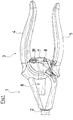
- the instrument shown with reference to the figures is an endoscopic needle holder 1, the basic structure of which belongs to the prior art.
- the actual tool, the needle holder is arranged at the distal end of a shaft 2, which in a proximal handle 3 is received.
- the tool can be actuated via a control rod guided in the shaft 2, the actuation takes place by means of the handle 3.
- the handle 3 has a rigidly connected thereto handle 4 and a pivotally mounted thereto handle 5, which is pivotable about an axis of rotation 6.
- the handle 5 is spring-loaded relative to the handle 4 in the opening direction, this is incorporated within the handle 3 about the axis of rotation 6 a helical torsion spring whose ends are supported on the one hand on the handle 4 and on the other hand on the handle 5, so that the grips against the in Fig. 1 illustrated closed position are spring-biased. In this closed position, the tool is also closed, ie a needle gripped with the needle holder held.
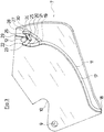
- the latching mechanism is formed between the gripping pieces 4 and 5 and has a web component 7 and a guide component 8 engaged therewith.
- the railway component 7, which in Fig. 3 is shown in detail, is fixed positively on the handle 4, on the one hand by a rotation axis 6 forming bolt, which passes through a hole 9 and the other by a positive engagement means which engages in an edge recess 10 and together with the determination at the bore 9 ensures that the web component 7 is firmly and rigidly connected to the handle 4.
- the track member 7 is plate-shaped and may be formed for example by a stainless steel sheet, it has a guide rail 11, which is described below in detail and a locking body in the form of a pin 12, which is opposite to the in Fig. 3 visible surface (out of the plane of the paper).
- the railway component 7 is in operative connection with the guide component 8, which is in Fig. 4 is shown.
- the guide member 8 is also formed as a flat component, in the manner of a leaf spring. It has at its one end a bore 13, with which it is pivotally fixed to the inside of the handle 5, as shown by Fig. 1 is apparent.
- a guide body in the form of a guide pin 14 is arranged, which rises vertically from the sheet member 8 and has a cylindrical shape. This pin 14 extends perpendicular to a roofed plane, which is spanned when pivoting the handle 5 about the axis 6 relative to the handle 4.
- a recessed surface 15 which forms a guide surface and is completed at the end of a parallel to the pin 12 projecting locking receptacle 16.
- This locking receptacle 16 has the cross-sectional shape of a crescent moon whose outward curvature is formed by the rounded shape of the free end of the guide member 8 and whose retracted inside the pin 12 opposite.
- the shape of the guide member 8 from its handle piece side end near the bore 13 to the free end however, in particular in the last third with increasing material thickness decreasing width formed so that the grip piece end more spring function takes over, whereas the free end can be considered rather rigid.
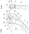
- the guide pin 14 clearly protrudes further than the projection 16 forming the projection so that in the installed position (see Fig. 1 and 2 ) engages the pin 14 in the guide track 11, which leads the pin 14 side.
- This base 17 runs flat and parallel to the component surface from a lateral inlet opening 8 to the beginning 19 of a circumferential guide track section.
- This circumferential guideway portion has two inclined surfaces 20, 21, namely in Fig. 3 right inclined surface 20, the obliquely downward from the beginning of the circumferential guideway portion 19, ie in the plane of the paper Fig. 3 into a deeper level and an in Fig. 3 left inclined surface 21, which leads from a level 17 of the guide track 11 further upwards.
- the guide pin 14 When the gripping pieces 4 and 5 move toward one another, the guide pin 14 is moved along the guide track 11 to the beginning of the circulating guide track section 19. Due to its arrangement acts on the pin 14 a based on Fig. 3 to the left acting force, which causes the further compression of the grips 4 and 5 of the pin 14 in the in Fig. 3 left branch of the rotating guide section passes there first to be brought over the inclined surface 21 to a higher level. When the grips 4 and 5 are maximally compressed, then the guide pin 14 is located at the end of in Fig. 3 left part of the circumferential guide track section, which forms a deflection region 22. Here, the guideway makes a right turn when viewed in the intended direction of passage.
- the pin 14 moves, because he can not back into the short track area 26 due to the step 27, via the inclined surface 20 back to the beginning 19 of the rotating track section and from there to the elongated part of Guideway 11.
- the guide pin 14 thus makes in the pass direction first in the deflection region 22 a right turn, then passes through an oppositely directed deflection in the region of the step 25, so makes a left turn to then again in the deflection 28 a right turn to go through.
- the guide pin 14 running in the guide track 11 is used exclusively for the web guide and not for the latching function.
- the latter is achieved by the latching body 12 in conjunction with the latching receptacle 16, wherein in particular of importance that the holding forces for the latching function are absorbed by these two components 12, 16 and not by the guide pin 14 and the guideway in the rest position so far is load-free.
- the locking pin 12 runs with little play outside the guide track 11 next to the guide pin 14 of the kind that when passing through the guide pin 14 through the circumferential guide track section from the beginning 19 to the deflection 22, the locking receptacle 16 moves so that the locking pin 12 between the locking receptacle 16th and the guide pin 14 is arranged.
- the locking receptacle 16 comes to rest on the locking pin 12.
- the recessed surface 15 ensures that rests against the end face of the locking pin 12 and for a power dissipation of the guide pin 14 in the axial direction.
- the locking receptacle 16 is then moved via a step 29, to which an inclined surface 30 connects, which opens into the surface of the web component 7.
- the locking mechanism is covered within the handle 3 to one side by the smooth outside of the web component 7 and the other side by a protective cover 31, so that this area is practically inaccessible from the outside, so that both the locking function and the leadership function in the area the encircling guideway are completely protected.
- a track component 7 'and a guide component 8' are provided, which differs from the previously described embodiment in that the step 29 and the inclined surface 30 of the track component 7 are absent in the track component 7 ', ie these areas can be used in the embodiment according to FIG railway component 7 'remain unprocessed, but within the guide track 11, the step 25 is replaced by an inclined surface 34.
- the guide component 8 ' has no continuous recessed surface 15 but a surface 15', to which a level 33 is followed by a level higher surface 32.
- the surfaces 32 and 15 ' form guide surfaces and are effective as soon as these areas pass over the end face of the locking pin 12.
- step 33 of the guide member 8 ' there replaced the step 33 of the guide member 8 ', the step 29 in the web component 7.
- This thus ensures that under relief of the guide pin 14 of the locking pin 12 passes after overcoming the step 33 on the recessed surface 15' fitting in its defined position in the locking receptacle 16 from which, because of the step 33, it is only possible to move in the direction of the guide pin 14 through the short track area 26 to the deflection area 28.
- the inclined surface 34 ensures that the guide pin 14 is again guided to a higher level in order then to fall down the step 27 blocking a rearward movement.
- Embodiments of a web component 7 "and a guide member 8" are shown, which differ from the embodiments described above in that both the locking pin 12 "and the guide pin 14", the front side of the locking pin 12 "co-axially adjoins the guide member 8" is arranged, whereas the locking receptacle 16 "on the web component 7" is arranged.
- guiding and locking function are also separated from each other, however, the guide pin 14 continues “the locking pin 12" with a smaller cross section. Accordingly, guide surfaces 35 are provided in the circumferential guideway portion in which the frontal gradation of the locking pin 12 "takes over the axial guidance and the pin 12" receives the forces in connection with locking receptacle 16 "in the locking position.
Applications Claiming Priority (1)
| Application Number | Priority Date | Filing Date | Title |
|---|---|---|---|
| DE102017204010.6A DE102017204010A1 (de) | 2017-03-10 | 2017-03-10 | Medizinisches Instrument |
Publications (2)
| Publication Number | Publication Date |
|---|---|
| EP3372176A1 true EP3372176A1 (fr) | 2018-09-12 |
| EP3372176B1 EP3372176B1 (fr) | 2019-09-04 |
Family
ID=61598916
Family Applications (1)
| Application Number | Title | Priority Date | Filing Date |
|---|---|---|---|
| EP18160451.3A Active EP3372176B1 (fr) | 2017-03-10 | 2018-03-07 | Instrument médical |
Country Status (4)
| Country | Link |
|---|---|
| US (1) | US10828063B2 (fr) |
| EP (1) | EP3372176B1 (fr) |
| DE (1) | DE102017204010A1 (fr) |
| ES (1) | ES2761053T3 (fr) |
Citations (5)
| Publication number | Priority date | Publication date | Assignee | Title |
|---|---|---|---|---|
| DE4207124C1 (en) | 1992-03-06 | 1993-06-17 | Dufner Instrumente Gmbh Fabrik Aerztlicher Instrumente Medizintechnik, 7200 Tuttlingen, De | Grip stop for surgical instrument - has two grip parts movable counter to one another on which are fitted two stop parts |
| JPH07275253A (ja) * | 1994-04-05 | 1995-10-24 | Terumo Corp | 外科用器具 |
| DE102012211200A1 (de) * | 2012-06-28 | 2014-01-02 | Olympus Winter & Ibe Gmbh | Greifinstrument |
| WO2015168441A1 (fr) * | 2014-04-30 | 2015-11-05 | Vanderbilt University | Dispositif chirurgical de saisie |
| DE102014110881A1 (de) | 2014-07-31 | 2016-02-04 | Aesculap Ag | Chirurgisches Instrument mit Handgriff und Griffsperre |
Family Cites Families (1)
| Publication number | Priority date | Publication date | Assignee | Title |
|---|---|---|---|---|
| JP3763699B2 (ja) | 1999-05-06 | 2006-04-05 | アルプス電気株式会社 | 押釦スイッチ |
-
2017
- 2017-03-10 DE DE102017204010.6A patent/DE102017204010A1/de not_active Withdrawn
-
2018
- 2018-03-07 EP EP18160451.3A patent/EP3372176B1/fr active Active
- 2018-03-07 ES ES18160451T patent/ES2761053T3/es active Active
- 2018-03-09 US US15/917,283 patent/US10828063B2/en active Active
Patent Citations (5)
| Publication number | Priority date | Publication date | Assignee | Title |
|---|---|---|---|---|
| DE4207124C1 (en) | 1992-03-06 | 1993-06-17 | Dufner Instrumente Gmbh Fabrik Aerztlicher Instrumente Medizintechnik, 7200 Tuttlingen, De | Grip stop for surgical instrument - has two grip parts movable counter to one another on which are fitted two stop parts |
| JPH07275253A (ja) * | 1994-04-05 | 1995-10-24 | Terumo Corp | 外科用器具 |
| DE102012211200A1 (de) * | 2012-06-28 | 2014-01-02 | Olympus Winter & Ibe Gmbh | Greifinstrument |
| WO2015168441A1 (fr) * | 2014-04-30 | 2015-11-05 | Vanderbilt University | Dispositif chirurgical de saisie |
| DE102014110881A1 (de) | 2014-07-31 | 2016-02-04 | Aesculap Ag | Chirurgisches Instrument mit Handgriff und Griffsperre |
Also Published As
| Publication number | Publication date |
|---|---|
| DE102017204010A1 (de) | 2018-09-13 |
| EP3372176B1 (fr) | 2019-09-04 |
| US10828063B2 (en) | 2020-11-10 |
| US20180263656A1 (en) | 2018-09-20 |
| ES2761053T3 (es) | 2020-05-18 |
Similar Documents
| Publication | Publication Date | Title |
|---|---|---|
| DE2642008C3 (de) | Handzange zum Abisolieren von Leiterenden | |
| DE3038880C2 (de) | Vorrichtung zur stufenweisen Abstandsverstellung von zwei Stuhlteilen | |
| EP0084324A1 (fr) | Dispositif de réglage en longueur pour une fixation de ski | |
| EP1053900A2 (fr) | Système de verrouillage pour capote de convertible | |
| EP1110612A2 (fr) | Système de pipetage avec pipette et embout-seringue | |
| DE202011052256U1 (de) | Medizinisches Instrument | |
| DE4422076C2 (de) | Bindungseinrichtung zwischen einem Schuh und einem Sportgerät, insbesondere Schibindung | |
| DE102009058583B4 (de) | Schiebetüre für ein Fahrzeug | |
| DE102018130016A1 (de) | Schiebedachsystem für ein Kraftfahrzeug | |
| DE3020788C2 (de) | Innenverschlußeinrichtung für einen Weichenantrieb | |
| EP1834544A1 (fr) | Verrouillage pour tables de ping-pong dotée de demi-panneaux pivotants | |
| EP3563973B1 (fr) | Pince | |
| EP2921260A1 (fr) | Appareil à entraînement pneumatique | |
| EP3372176B1 (fr) | Instrument médical | |
| DE102011056235A1 (de) | Medizinisches Instrument | |
| EP1470951B1 (fr) | Dispositif de réglage à cliquets | |
| DE1531344C3 (de) | Vorrichtung zum Ziehen und/oder Heben eines Seiles | |
| DE10105847B4 (de) | Mitnahmevorrichtung für ausziehbaren Möbelboden | |
| EP2236233B1 (fr) | Scie sauteuse | |
| DE102007040895A1 (de) | Presszange zum radialen Verpressen von Rohren, Rohrstücken und dergleichen | |
| EP3735919B1 (fr) | Instrument médical | |
| DE102004011054B4 (de) | Ratschenartige Verstellvorrichtung | |
| DE102010020655A1 (de) | Wasserpumpenzange | |
| EP3849435B1 (fr) | Instrument chirurgical | |
| DE102018112324B4 (de) | Handwerkzeugmaschine mit einem Führungskörper und einem Verstellmechanismus für den Führungskörper |
Legal Events
| Date | Code | Title | Description |
|---|---|---|---|
| PUAI | Public reference made under article 153(3) epc to a published international application that has entered the european phase |
Free format text: ORIGINAL CODE: 0009012 |
|
| STAA | Information on the status of an ep patent application or granted ep patent |
Free format text: STATUS: THE APPLICATION HAS BEEN PUBLISHED |
|
| AK | Designated contracting states |
Kind code of ref document: A1 Designated state(s): AL AT BE BG CH CY CZ DE DK EE ES FI FR GB GR HR HU IE IS IT LI LT LU LV MC MK MT NL NO PL PT RO RS SE SI SK SM TR |
|
| AX | Request for extension of the european patent |
Extension state: BA ME |
|
| STAA | Information on the status of an ep patent application or granted ep patent |
Free format text: STATUS: REQUEST FOR EXAMINATION WAS MADE |
|
| 17P | Request for examination filed |
Effective date: 20181108 |
|
| RBV | Designated contracting states (corrected) |
Designated state(s): AL AT BE BG CH CY CZ DE DK EE ES FI FR GB GR HR HU IE IS IT LI LT LU LV MC MK MT NL NO PL PT RO RS SE SI SK SM TR |
|
| GRAP | Despatch of communication of intention to grant a patent |
Free format text: ORIGINAL CODE: EPIDOSNIGR1 |
|
| STAA | Information on the status of an ep patent application or granted ep patent |
Free format text: STATUS: GRANT OF PATENT IS INTENDED |
|
| RIC1 | Information provided on ipc code assigned before grant |
Ipc: A61B 17/04 20060101ALI20190313BHEP Ipc: A61B 17/28 20060101AFI20190313BHEP Ipc: A61B 17/00 20060101ALI20190313BHEP Ipc: A61B 17/062 20060101ALI20190313BHEP Ipc: A61B 17/29 20060101ALI20190313BHEP |
|
| INTG | Intention to grant announced |
Effective date: 20190411 |
|
| GRAS | Grant fee paid |
Free format text: ORIGINAL CODE: EPIDOSNIGR3 |
|
| GRAA | (expected) grant |
Free format text: ORIGINAL CODE: 0009210 |
|
| STAA | Information on the status of an ep patent application or granted ep patent |
Free format text: STATUS: THE PATENT HAS BEEN GRANTED |
|
| AK | Designated contracting states |
Kind code of ref document: B1 Designated state(s): AL AT BE BG CH CY CZ DE DK EE ES FI FR GB GR HR HU IE IS IT LI LT LU LV MC MK MT NL NO PL PT RO RS SE SI SK SM TR |
|
| REG | Reference to a national code |
Ref country code: GB Ref legal event code: FG4D Free format text: NOT ENGLISH |
|
| REG | Reference to a national code |
Ref country code: CH Ref legal event code: EP |
|
| REG | Reference to a national code |
Ref country code: AT Ref legal event code: REF Ref document number: 1174263 Country of ref document: AT Kind code of ref document: T Effective date: 20190915 |
|
| REG | Reference to a national code |
Ref country code: DE Ref legal event code: R096 Ref document number: 502018000183 Country of ref document: DE |
|
| REG | Reference to a national code |
Ref country code: IE Ref legal event code: FG4D Free format text: LANGUAGE OF EP DOCUMENT: GERMAN |
|
| REG | Reference to a national code |
Ref country code: CH Ref legal event code: NV Representative=s name: ISLER AND PEDRAZZINI AG, CH |
|
| REG | Reference to a national code |
Ref country code: NL Ref legal event code: MP Effective date: 20190904 |
|
| REG | Reference to a national code |
Ref country code: LT Ref legal event code: MG4D |
|
| PG25 | Lapsed in a contracting state [announced via postgrant information from national office to epo] |
Ref country code: BG Free format text: LAPSE BECAUSE OF FAILURE TO SUBMIT A TRANSLATION OF THE DESCRIPTION OR TO PAY THE FEE WITHIN THE PRESCRIBED TIME-LIMIT Effective date: 20191204 Ref country code: SE Free format text: LAPSE BECAUSE OF FAILURE TO SUBMIT A TRANSLATION OF THE DESCRIPTION OR TO PAY THE FEE WITHIN THE PRESCRIBED TIME-LIMIT Effective date: 20190904 Ref country code: NO Free format text: LAPSE BECAUSE OF FAILURE TO SUBMIT A TRANSLATION OF THE DESCRIPTION OR TO PAY THE FEE WITHIN THE PRESCRIBED TIME-LIMIT Effective date: 20191204 Ref country code: LT Free format text: LAPSE BECAUSE OF FAILURE TO SUBMIT A TRANSLATION OF THE DESCRIPTION OR TO PAY THE FEE WITHIN THE PRESCRIBED TIME-LIMIT Effective date: 20190904 Ref country code: FI Free format text: LAPSE BECAUSE OF FAILURE TO SUBMIT A TRANSLATION OF THE DESCRIPTION OR TO PAY THE FEE WITHIN THE PRESCRIBED TIME-LIMIT Effective date: 20190904 Ref country code: HR Free format text: LAPSE BECAUSE OF FAILURE TO SUBMIT A TRANSLATION OF THE DESCRIPTION OR TO PAY THE FEE WITHIN THE PRESCRIBED TIME-LIMIT Effective date: 20190904 |
|
| PG25 | Lapsed in a contracting state [announced via postgrant information from national office to epo] |
Ref country code: LV Free format text: LAPSE BECAUSE OF FAILURE TO SUBMIT A TRANSLATION OF THE DESCRIPTION OR TO PAY THE FEE WITHIN THE PRESCRIBED TIME-LIMIT Effective date: 20190904 Ref country code: GR Free format text: LAPSE BECAUSE OF FAILURE TO SUBMIT A TRANSLATION OF THE DESCRIPTION OR TO PAY THE FEE WITHIN THE PRESCRIBED TIME-LIMIT Effective date: 20191205 Ref country code: AL Free format text: LAPSE BECAUSE OF FAILURE TO SUBMIT A TRANSLATION OF THE DESCRIPTION OR TO PAY THE FEE WITHIN THE PRESCRIBED TIME-LIMIT Effective date: 20190904 Ref country code: RS Free format text: LAPSE BECAUSE OF FAILURE TO SUBMIT A TRANSLATION OF THE DESCRIPTION OR TO PAY THE FEE WITHIN THE PRESCRIBED TIME-LIMIT Effective date: 20190904 |
|
| PG25 | Lapsed in a contracting state [announced via postgrant information from national office to epo] |
Ref country code: EE Free format text: LAPSE BECAUSE OF FAILURE TO SUBMIT A TRANSLATION OF THE DESCRIPTION OR TO PAY THE FEE WITHIN THE PRESCRIBED TIME-LIMIT Effective date: 20190904 Ref country code: NL Free format text: LAPSE BECAUSE OF FAILURE TO SUBMIT A TRANSLATION OF THE DESCRIPTION OR TO PAY THE FEE WITHIN THE PRESCRIBED TIME-LIMIT Effective date: 20190904 Ref country code: RO Free format text: LAPSE BECAUSE OF FAILURE TO SUBMIT A TRANSLATION OF THE DESCRIPTION OR TO PAY THE FEE WITHIN THE PRESCRIBED TIME-LIMIT Effective date: 20190904 Ref country code: PL Free format text: LAPSE BECAUSE OF FAILURE TO SUBMIT A TRANSLATION OF THE DESCRIPTION OR TO PAY THE FEE WITHIN THE PRESCRIBED TIME-LIMIT Effective date: 20190904 Ref country code: PT Free format text: LAPSE BECAUSE OF FAILURE TO SUBMIT A TRANSLATION OF THE DESCRIPTION OR TO PAY THE FEE WITHIN THE PRESCRIBED TIME-LIMIT Effective date: 20200106 |
|
| REG | Reference to a national code |
Ref country code: ES Ref legal event code: FG2A Ref document number: 2761053 Country of ref document: ES Kind code of ref document: T3 Effective date: 20200518 |
|
| PG25 | Lapsed in a contracting state [announced via postgrant information from national office to epo] |
Ref country code: IS Free format text: LAPSE BECAUSE OF FAILURE TO SUBMIT A TRANSLATION OF THE DESCRIPTION OR TO PAY THE FEE WITHIN THE PRESCRIBED TIME-LIMIT Effective date: 20200224 Ref country code: SK Free format text: LAPSE BECAUSE OF FAILURE TO SUBMIT A TRANSLATION OF THE DESCRIPTION OR TO PAY THE FEE WITHIN THE PRESCRIBED TIME-LIMIT Effective date: 20190904 Ref country code: CZ Free format text: LAPSE BECAUSE OF FAILURE TO SUBMIT A TRANSLATION OF THE DESCRIPTION OR TO PAY THE FEE WITHIN THE PRESCRIBED TIME-LIMIT Effective date: 20190904 Ref country code: SM Free format text: LAPSE BECAUSE OF FAILURE TO SUBMIT A TRANSLATION OF THE DESCRIPTION OR TO PAY THE FEE WITHIN THE PRESCRIBED TIME-LIMIT Effective date: 20190904 |
|
| REG | Reference to a national code |
Ref country code: DE Ref legal event code: R097 Ref document number: 502018000183 Country of ref document: DE |
|
| PLBE | No opposition filed within time limit |
Free format text: ORIGINAL CODE: 0009261 |
|
| STAA | Information on the status of an ep patent application or granted ep patent |
Free format text: STATUS: NO OPPOSITION FILED WITHIN TIME LIMIT |
|
| PG2D | Information on lapse in contracting state deleted |
Ref country code: IS |
|
| PG25 | Lapsed in a contracting state [announced via postgrant information from national office to epo] |
Ref country code: DK Free format text: LAPSE BECAUSE OF FAILURE TO SUBMIT A TRANSLATION OF THE DESCRIPTION OR TO PAY THE FEE WITHIN THE PRESCRIBED TIME-LIMIT Effective date: 20190904 Ref country code: IS Free format text: LAPSE BECAUSE OF FAILURE TO SUBMIT A TRANSLATION OF THE DESCRIPTION OR TO PAY THE FEE WITHIN THE PRESCRIBED TIME-LIMIT Effective date: 20200105 |
|
| 26N | No opposition filed |
Effective date: 20200605 |
|
| PG25 | Lapsed in a contracting state [announced via postgrant information from national office to epo] |
Ref country code: SI Free format text: LAPSE BECAUSE OF FAILURE TO SUBMIT A TRANSLATION OF THE DESCRIPTION OR TO PAY THE FEE WITHIN THE PRESCRIBED TIME-LIMIT Effective date: 20190904 |
|
| PG25 | Lapsed in a contracting state [announced via postgrant information from national office to epo] |
Ref country code: MC Free format text: LAPSE BECAUSE OF FAILURE TO SUBMIT A TRANSLATION OF THE DESCRIPTION OR TO PAY THE FEE WITHIN THE PRESCRIBED TIME-LIMIT Effective date: 20190904 |
|
| REG | Reference to a national code |
Ref country code: BE Ref legal event code: MM Effective date: 20200331 |
|
| PG25 | Lapsed in a contracting state [announced via postgrant information from national office to epo] |
Ref country code: LU Free format text: LAPSE BECAUSE OF NON-PAYMENT OF DUE FEES Effective date: 20200307 |
|
| PG25 | Lapsed in a contracting state [announced via postgrant information from national office to epo] |
Ref country code: IE Free format text: LAPSE BECAUSE OF NON-PAYMENT OF DUE FEES Effective date: 20200307 |
|
| PG25 | Lapsed in a contracting state [announced via postgrant information from national office to epo] |
Ref country code: BE Free format text: LAPSE BECAUSE OF NON-PAYMENT OF DUE FEES Effective date: 20200331 |
|
| PG25 | Lapsed in a contracting state [announced via postgrant information from national office to epo] |
Ref country code: MT Free format text: LAPSE BECAUSE OF FAILURE TO SUBMIT A TRANSLATION OF THE DESCRIPTION OR TO PAY THE FEE WITHIN THE PRESCRIBED TIME-LIMIT Effective date: 20190904 Ref country code: CY Free format text: LAPSE BECAUSE OF FAILURE TO SUBMIT A TRANSLATION OF THE DESCRIPTION OR TO PAY THE FEE WITHIN THE PRESCRIBED TIME-LIMIT Effective date: 20190904 |
|
| PG25 | Lapsed in a contracting state [announced via postgrant information from national office to epo] |
Ref country code: MK Free format text: LAPSE BECAUSE OF FAILURE TO SUBMIT A TRANSLATION OF THE DESCRIPTION OR TO PAY THE FEE WITHIN THE PRESCRIBED TIME-LIMIT Effective date: 20190904 |
|
| PGFP | Annual fee paid to national office [announced via postgrant information from national office to epo] |
Ref country code: FR Payment date: 20230321 Year of fee payment: 6 |
|
| PGFP | Annual fee paid to national office [announced via postgrant information from national office to epo] |
Ref country code: TR Payment date: 20230306 Year of fee payment: 6 Ref country code: GB Payment date: 20230323 Year of fee payment: 6 Ref country code: DE Payment date: 20230320 Year of fee payment: 6 |
|
| PGFP | Annual fee paid to national office [announced via postgrant information from national office to epo] |
Ref country code: IT Payment date: 20230331 Year of fee payment: 6 Ref country code: ES Payment date: 20230414 Year of fee payment: 6 Ref country code: CH Payment date: 20230402 Year of fee payment: 6 |