EP3370280A1 - Elektrode für sekundärbatterie mit feinen löchern - Google Patents
Elektrode für sekundärbatterie mit feinen löchern Download PDFInfo
- Publication number
- EP3370280A1 EP3370280A1 EP17843899.0A EP17843899A EP3370280A1 EP 3370280 A1 EP3370280 A1 EP 3370280A1 EP 17843899 A EP17843899 A EP 17843899A EP 3370280 A1 EP3370280 A1 EP 3370280A1
- Authority
- EP
- European Patent Office
- Prior art keywords
- mixture layer
- electrode
- electrode mixture
- fine holes
- current collector
- Prior art date
- Legal status (The legal status is an assumption and is not a legal conclusion. Google has not performed a legal analysis and makes no representation as to the accuracy of the status listed.)
- Granted
Links
Images



Classifications
-
- H—ELECTRICITY
- H01—ELECTRIC ELEMENTS
- H01M—PROCESSES OR MEANS, e.g. BATTERIES, FOR THE DIRECT CONVERSION OF CHEMICAL ENERGY INTO ELECTRICAL ENERGY
- H01M4/00—Electrodes
- H01M4/02—Electrodes composed of, or comprising, active material
- H01M4/64—Carriers or collectors
- H01M4/66—Selection of materials
- H01M4/665—Composites
-
- H—ELECTRICITY
- H01—ELECTRIC ELEMENTS
- H01M—PROCESSES OR MEANS, e.g. BATTERIES, FOR THE DIRECT CONVERSION OF CHEMICAL ENERGY INTO ELECTRICAL ENERGY
- H01M10/00—Secondary cells; Manufacture thereof
- H01M10/05—Accumulators with non-aqueous electrolyte
- H01M10/052—Li-accumulators
- H01M10/0525—Rocking-chair batteries, i.e. batteries with lithium insertion or intercalation in both electrodes; Lithium-ion batteries
-
- H—ELECTRICITY
- H01—ELECTRIC ELEMENTS
- H01M—PROCESSES OR MEANS, e.g. BATTERIES, FOR THE DIRECT CONVERSION OF CHEMICAL ENERGY INTO ELECTRICAL ENERGY
- H01M4/00—Electrodes
- H01M4/02—Electrodes composed of, or comprising, active material
- H01M4/04—Processes of manufacture in general
- H01M4/0402—Methods of deposition of the material
- H01M4/0404—Methods of deposition of the material by coating on electrode collectors
-
- H—ELECTRICITY
- H01—ELECTRIC ELEMENTS
- H01M—PROCESSES OR MEANS, e.g. BATTERIES, FOR THE DIRECT CONVERSION OF CHEMICAL ENERGY INTO ELECTRICAL ENERGY
- H01M4/00—Electrodes
- H01M4/02—Electrodes composed of, or comprising, active material
- H01M4/04—Processes of manufacture in general
- H01M4/043—Processes of manufacture in general involving compressing or compaction
- H01M4/0435—Rolling or calendering
-
- H—ELECTRICITY
- H01—ELECTRIC ELEMENTS
- H01M—PROCESSES OR MEANS, e.g. BATTERIES, FOR THE DIRECT CONVERSION OF CHEMICAL ENERGY INTO ELECTRICAL ENERGY
- H01M4/00—Electrodes
- H01M4/02—Electrodes composed of, or comprising, active material
- H01M4/13—Electrodes for accumulators with non-aqueous electrolyte, e.g. for lithium-accumulators; Processes of manufacture thereof
-
- H—ELECTRICITY
- H01—ELECTRIC ELEMENTS
- H01M—PROCESSES OR MEANS, e.g. BATTERIES, FOR THE DIRECT CONVERSION OF CHEMICAL ENERGY INTO ELECTRICAL ENERGY
- H01M4/00—Electrodes
- H01M4/02—Electrodes composed of, or comprising, active material
- H01M4/13—Electrodes for accumulators with non-aqueous electrolyte, e.g. for lithium-accumulators; Processes of manufacture thereof
- H01M4/136—Electrodes based on inorganic compounds other than oxides or hydroxides, e.g. sulfides, selenides, tellurides, halogenides or LiCoFy
-
- H—ELECTRICITY
- H01—ELECTRIC ELEMENTS
- H01M—PROCESSES OR MEANS, e.g. BATTERIES, FOR THE DIRECT CONVERSION OF CHEMICAL ENERGY INTO ELECTRICAL ENERGY
- H01M4/00—Electrodes
- H01M4/02—Electrodes composed of, or comprising, active material
- H01M4/13—Electrodes for accumulators with non-aqueous electrolyte, e.g. for lithium-accumulators; Processes of manufacture thereof
- H01M4/139—Processes of manufacture
-
- H—ELECTRICITY
- H01—ELECTRIC ELEMENTS
- H01M—PROCESSES OR MEANS, e.g. BATTERIES, FOR THE DIRECT CONVERSION OF CHEMICAL ENERGY INTO ELECTRICAL ENERGY
- H01M4/00—Electrodes
- H01M4/02—Electrodes composed of, or comprising, active material
- H01M4/36—Selection of substances as active materials, active masses, active liquids
- H01M4/362—Composites
- H01M4/364—Composites as mixtures
-
- H—ELECTRICITY
- H01—ELECTRIC ELEMENTS
- H01M—PROCESSES OR MEANS, e.g. BATTERIES, FOR THE DIRECT CONVERSION OF CHEMICAL ENERGY INTO ELECTRICAL ENERGY
- H01M4/00—Electrodes
- H01M4/02—Electrodes composed of, or comprising, active material
- H01M2004/021—Physical characteristics, e.g. porosity, surface area
-
- H—ELECTRICITY
- H01—ELECTRIC ELEMENTS
- H01M—PROCESSES OR MEANS, e.g. BATTERIES, FOR THE DIRECT CONVERSION OF CHEMICAL ENERGY INTO ELECTRICAL ENERGY
- H01M4/00—Electrodes
- H01M4/02—Electrodes composed of, or comprising, active material
- H01M2004/026—Electrodes composed of, or comprising, active material characterised by the polarity
- H01M2004/027—Negative electrodes
-
- H—ELECTRICITY
- H01—ELECTRIC ELEMENTS
- H01M—PROCESSES OR MEANS, e.g. BATTERIES, FOR THE DIRECT CONVERSION OF CHEMICAL ENERGY INTO ELECTRICAL ENERGY
- H01M4/00—Electrodes
- H01M4/02—Electrodes composed of, or comprising, active material
- H01M2004/026—Electrodes composed of, or comprising, active material characterised by the polarity
- H01M2004/028—Positive electrodes
-
- H—ELECTRICITY
- H01—ELECTRIC ELEMENTS
- H01M—PROCESSES OR MEANS, e.g. BATTERIES, FOR THE DIRECT CONVERSION OF CHEMICAL ENERGY INTO ELECTRICAL ENERGY
- H01M4/00—Electrodes
- H01M4/02—Electrodes composed of, or comprising, active material
- H01M4/13—Electrodes for accumulators with non-aqueous electrolyte, e.g. for lithium-accumulators; Processes of manufacture thereof
- H01M4/139—Processes of manufacture
- H01M4/1393—Processes of manufacture of electrodes based on carbonaceous material, e.g. graphite-intercalation compounds or CFx
-
- Y—GENERAL TAGGING OF NEW TECHNOLOGICAL DEVELOPMENTS; GENERAL TAGGING OF CROSS-SECTIONAL TECHNOLOGIES SPANNING OVER SEVERAL SECTIONS OF THE IPC; TECHNICAL SUBJECTS COVERED BY FORMER USPC CROSS-REFERENCE ART COLLECTIONS [XRACs] AND DIGESTS
- Y02—TECHNOLOGIES OR APPLICATIONS FOR MITIGATION OR ADAPTATION AGAINST CLIMATE CHANGE
- Y02E—REDUCTION OF GREENHOUSE GAS [GHG] EMISSIONS, RELATED TO ENERGY GENERATION, TRANSMISSION OR DISTRIBUTION
- Y02E60/00—Enabling technologies; Technologies with a potential or indirect contribution to GHG emissions mitigation
- Y02E60/10—Energy storage using batteries
-
- Y—GENERAL TAGGING OF NEW TECHNOLOGICAL DEVELOPMENTS; GENERAL TAGGING OF CROSS-SECTIONAL TECHNOLOGIES SPANNING OVER SEVERAL SECTIONS OF THE IPC; TECHNICAL SUBJECTS COVERED BY FORMER USPC CROSS-REFERENCE ART COLLECTIONS [XRACs] AND DIGESTS
- Y02—TECHNOLOGIES OR APPLICATIONS FOR MITIGATION OR ADAPTATION AGAINST CLIMATE CHANGE
- Y02P—CLIMATE CHANGE MITIGATION TECHNOLOGIES IN THE PRODUCTION OR PROCESSING OF GOODS
- Y02P70/00—Climate change mitigation technologies in the production process for final industrial or consumer products
- Y02P70/50—Manufacturing or production processes characterised by the final manufactured product
Definitions
- the present disclosure relates to an electrode for a secondary battery having fine holes.
- the demand for lithium secondary batteries, such as lithium ion batteries and lithium ion polymer batteries, exhibiting high energy density, discharge voltage, and output stability is very high.
- an electrode assembly constituting the secondary battery has a structure in which a positive electrode and a negative electrode are manufactured and a separator is interposed between the positive electrode and the negative electrode by forming an electrode mixture layer including an electrode active material formed on one surface or both surfaces of the electrode assembly.
- the capacity of the electrode assembly is maximized.
- the present disclosure is provided to solve the above technical problems of the related art.
- the inventors of the present disclosure have conducted intensive research and various experiments and have found that, by including a plurality of horn-shaped fine holes whose diameters are gradually decreased from a vertical cross-sectional surface toward a current collector in an electrode mixture layer, an electrolytic solution may be more easily diffused through the fine holes in a depth direction of the electrode mixture layer, accordingly it is possible to prevent a Li-plating phenomenon from occurring despite a high loading amount of the electrode mixture layer, thereby preventing electrical performance deterioration of an electrode.
- the inventors also found that, in a charging/discharging process, a movement of lithium ions may be smoothed, and thus rapid charging performance is improved, and compared with a conventional method of forming a pattern structure by using a laser, since the fine holes are formed by a mold or a roller including protrusions corresponding to the fine holes, it is possible to prevent the capacity of the electrode from being lowered and it is also possible to eliminate or substantially reduce a defect rate of a product caused by particles separated from the electrode mixture layer by the laser, thereby completing the present disclosure.
- the present disclosure provides an electrode for a secondary battery including an electrode mixture layer including an electrode active material on one surface or both surfaces of a current collector, wherein the electrode mixture layer includes a plurality of fine holes recessed toward the current collector from a vertical cross-sectional surface thereof, and each of the fine holes is a horn-shaped hole whose diameter is gradually decreased from the vertical cross-sectional surface toward the current collector in the electrode mixture layer.
- an electrolytic solution may be more easily diffused through the fine holes in a depth direction of the electrode mixture layer, and a Li-plating phenomenon may be prevented from occurring despite a high loading amount of the electrode mixture layer, thereby preventing electrical performance deterioration of the electrode. Also, in a charging/discharging process, a movement of lithium ions may be smoothed, and thus rapid charging performance may be improved.
- the fine holes may be formed in an electrode mixture layer having a loading amount of about 3.5 to 5.5 mAh/cm 2 and a porosity of about 25 to 35%.
- the ranges of the loading amount and the porosity of the electrode mixture layer are ranges in which the secondary battery including the electrode can exhibit a desired high capacity.
- the electrode for a secondary battery according to the present disclosure has an electrode mixture layer formed to have the above range of the loading amount and the porosity of the electrode mixture layer, unlike a conventional electrode, the electrolytic solution may be more easily diffused in the depth direction of the electrode mixture layer so that a desired effect may be exhibited.
- the capacity of the secondary battery including the electrode may not be improved.
- the loading amount of the electrode mixture layer is excessively large beyond the range or the porosity is excessively small beyond the range, the electrolytic solution may not be easily diffused even though the plurality of the fine holes are formed in the electrode mixture layer.
- a depth of the fine holes formed from a vertical cross-sectional surface toward the current collector may be 80 to 90% of the thickness of the electrode mixture layer corresponding thereto.
- the depth of the find holes is less than 80% of the thickness of the electrode mixture layer corresponding thereto, the depth of the fine holes is excessively low and the electrolytic solution may not be easily diffused in the depth direction of the electrode mixture layer, and thus the desired effect may not be exhibited.
- the depth of the find holes is more than 90% of the thickness of the electrode mixture layer corresponding thereto
- an excessively high pressure may be applied to an electrode mixture layer part located at an end part of the fine holes in a current collector direction so that the part may be rolled, the porosity of the electrode mixture layer may become excessively low, and the diffusion of the electrolytic solution may be deteriorated.
- a planar structure of the fine holes is not limited as long as the fine holes are recessed in a horn shape and their diameters are successively decreased from the vertical cross-sectional surface toward the current collector such that a desired effect is exhibited.
- the fine holes may be in the shape of a triangle, a quadrangle, a pentagon, a hexagon, a circle, a semicircle, or an ellipse on a plane on a surface part of the electrode mixture layer, and more particularly, the fine holes may be in the shape of a circle in consideration of a uniform diffusion of the electrolytic solution and a uniform delivery of pressure applied in a process of forming the fine holes.
- the fine holes may have an average diameter of about 100 to 200 micrometers at the vertical cross-sectional surface, and may have an average diameter of about 20 to 50 micrometers at an inner end part thereof.
- the average diameter at the vertical cross-sectional surface is less than 100 micrometers, the diameter of the fine holes at the surface part at which the electrolytic solution starts to flow is too small, and thus the diffusion of the electrolytic solution through the fine holes may be not easily performed. Conversely, when the average diameter at the vertical cross-sectional surface is more than 200 micrometers, the diameter of the fine holes at the surface part becomes excessively large, and thus the capacity of the electrode may be lowered.
- the average diameter at the inner end part is less than 20 micrometers, a protrusion of the fine hole forming mold or fine hole forming roller on the electrode mixture layer may become too thin so that the fine holes may not be easily formed by a pressure applied to the electrode mixture layer.
- the average diameter at the inner end part is more than 50 micrometers, the protrusion of the fine hole forming mold or fine hole forming roller on the electrode mixture layer may become too large, and thus the inner end part may be rolled due to the pressure applied to the electrode mixture layer, the porosity at the inner end part of the fine holes of the electrode mixture layer may be lowered, and the diffusion of the electrolytic solution may be deteriorated in the process of forming the fine holes.
- the inner end part of the fine holes may have a circular arc shape in the vertical cross-sectional surface so that the diameter of the inner end part refers to a diameter at a part at which a side edge of the fine hole formed in a linear shape and an end part of the arc shape come into contact with each other among end parts formed in the circular arc shape.
- a protrusion end part of the fine hole forming mold or fine hole forming roller corresponding thereto must also have a thin needle-shaped structure. Therefore, in the process of pressing by the mold or roller, the protrusion may be deformed, and thus the fine hole may not be easily formed in the electrode mixture layer.
- the plurality of fine holes may have a regular array structure on a plane on a surface part of the electrode mixture layer.
- the electrolytic solution may be more uniformly diffused to all parts of the electrode mixture layer, and performance deterioration due to a difference in local diffusion of the electrolytic solution may be prevented.
- the fine hole may have a structure in which its diameter is continuously or discontinuously decreased from the vertical cross-sectional surface toward the current collector, more particularly, may have a structure in which its diameter is gradually decreased due to pressure from the fine hole forming mold or fine hole forming roller so that fine holes may be formed more easily.
- a technique of forming a predetermined pattern on the electrode mixture layer while separating some of the electrode mixture layer from the electrode mixture layer using a laser may be used.
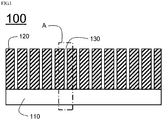
- FIG. 1 is a schematic view showing a vertical sectional structure of an electrode in which pattern-shaped fine holes are formed in an electrode mixture layer using a conventional laser
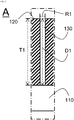
- FIG. 2 is a partial enlarged view schematically showing a structure of part "A" of FIG. 1 .
- an electrode mixture layer 120 may be formed on an upper surface of a current collector 110.
- a plurality of fine holes 130 may be formed in the electrode mixture layer 120 to form a predetermined pattern.
- a diameter R1 of each of the fine holes 130 may be substantially uniform from a vertical cross-sectional surface of the electrode mixture layer 120 toward the current collector 110 because the fine holes are formed by separating some of the electrode mixture layer 120 from the electrode mixture layer 120 using the laser.
- the fine holes 130 may be formed to have the depth D1 that is equal to a thickness T1 of the electrode mixture layer 120 to come into contact with an upper surface of the current collector 110.
- the total capacity of the electrode may be decreased because some of the electrode mixture layer is separated in a process of forming the fine holes, and in a process of manufacturing the electrode, separated electrode mixture layer particles may act as impurities that scatter in air and cause defects in a product. Therefore, an additional process or device may be required to prevent defects so that an overall manufacturing cost of the electrode may increase.
- the present disclosure provides a device for manufacturing the electrode for a secondary battery.
- the device includes a fine hole forming mold, and the fine hole forming mold has a structure in which horn-shaped protrusions corresponding to fine holes protrude from one surface thereof so that, when the one surface is pressed against a surface of an electrode mixture layer, horn-shaped fine holes recessed from a surface part of the electrode mixture layer toward a current collector may be formed.
- the device includes a fine hole forming roller, and the fine hole forming roller has a structure in which horn-shaped protrusions corresponding to fine holes protrude from an outer surface so that, when the outer surface is pressed against a surface of an electrode mixture layer, horn-shaped fine holes recessed from a surface part of the electrode mixture layer toward a current collector may be formed.
- the device for manufacturing the electrode for a secondary battery according to the present disclosure may have a structure in which the protrusions protruding from the mold or roller pressurize the electrode mixture layer to form the fine holes.
- some of the electrode mixture layer may not be separated from the electrode mixture layer, thereby preventing a capacity deterioration of an electrode and effectively preventing a problem of an increase of a product defect rate and an increase of a manufacturing cost that may occur due to the separated electrode mixture layer particles.
- the horn-shaped protrusions may have an average diameter of 100 to 200 micrometers at an end part having a relatively large diameter, and an average diameter of 20 to 50 micrometers at an end part having a relatively small diameter in a vertical cross-sectional surface.
- an electrolytic solution may be easily impregnated in a depth direction of the electrode mixture layer, it is possible to prevent the capacity of the electrode from being lowered, and it is also possible to prevent the electrode mixture layer from being rolled at an inner end part of the fine holes.
- the present disclosure provides a method of manufacturing the electrode for a secondary battery.
- the method includes: coating an electrode mixture slurry including an electrode active material on a current collector; drying and rolling the current collector coated with the electrode mixture slurry to form an electrode mixture layer; and forming a plurality of horn-shaped fine holes recessed into the electrode mixture layer by pressing a mold or a roller against the surface of the electrode mixture layer.
- the fine holes of the electrode mixture layer may be formed by pressing the fine hole forming mold or fine hole forming roller after the electrode mixture layer is formed.
- the electrode mixture layer formed in the above process may have a loading amount of about 3.5 to 5.5 mAh/cm 2 and a porosity of about 25 to 35%.
- the mold or roller may include fine hole forming protrusions in a shape corresponding to the horn-shaped fine holes at a part facing the surface of the dried and rolled electrode mixture layer.
- the fine holes of the electrode mixture layer may be formed by the fine hole forming protrusions formed in the mold or roller when pressure is applied to the surface of the electrode mixture layer by the mold or roller.
- each of the horn-shaped protrusions may be adjusted to a specific range.
- the electrolytic solution may be easily impregnated in a depth direction of the electrode mixture layer, it is possible to prevent the capacity of the electrode from being lowered, and it is also possible to prevent the electrode mixture layer from being rolled at an inner end part of the fine holes.
- each of the horn-shaped protrusions may have an average diameter of about 100 to 200 micrometers at an end part having a relatively large diameter, and an average diameter of about 20 to 50 micrometers at an end part having a relatively small diameter in a vertical cross-sectional surface.
- an electrode for a secondary battery is configured such that, by a plurality of horn-shaped fine holes whose diameters are successively decreased from a vertical cross-sectional surface toward a current collector being included in an electrode mixture layer, an electrolytic solution can be more easily diffused through the fine holes in a depth direction of the electrode mixture layer, accordingly it is possible to prevent a Li-plating phenomenon from occurring despite a high loading amount of the electrode mixture layer, thereby preventing electrical performance deterioration of an electrode, and, in a charging/discharging process, a movement of lithium ions may be smoothed, and thus rapid charging performance is improved.
- the fine holes are formed by a mold or a roller including protrusions corresponding to the fine holes, it is possible to prevent the capacity of the electrode from being lowered and it is also possible to eliminate or substantially reduce a defect rate of a product caused by particles separated from the electrode mixture layer by the laser.
- FIG. 3 is a schematic view showing a vertical cross-sectional structure of an electrode for a secondary battery according to an exemplary embodiment of the present disclosure
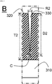
- FIG. 4 is a partial enlarged view schematically showing a structure of part "B" of FIG. 3
- FIG. 5 is a partial enlarged view schematically showing a structure of part "C" of FIG. 4 .
- an electrode mixture layer 320 is formed on an upper surface of a current collector 310.
- the electrode mixture layer 320 has a structure in which a plurality of fine holes 330 are regularly arranged.
- the fine holes 330 are recessed from a vertical cross-sectional surface toward the current collector 310 and have a horn shape in which diameters R2 and R3 are gradually decreased toward the current collector.
- a depth D2 of the fine hole 330 formed from a surface part thereof toward the current collector 310 may have a size of about 90% of a thickness T2 of the electrode mixture layer 320 corresponding thereto.
- the fine hole 330 may have an average diameter R2 of 100 to 200 micrometers at the surface part thereof and an average diameter R3 of 20 to 50 micrometers at an inner end part 332 thereof.
- the fine hole 330 may have the arc-shaped inner end part 332 on a vertical section thereof and accordingly, the average diameter R3 at the inner end part 332 may be the average diameter R3 at a part 333 at which a side edge 331 of the fine hole 330 formed in a straight line and the arc-shaped inner end part 332 come into contact with each other.
- FIGS. 6 and 7 are schematic views showing a process of forming fine holes in an electrode mixture layer using a device for manufacturing an electrode for a secondary battery according to another exemplary embodiment of the present disclosure.
- the device for manufacturing an electrode for a secondary battery may include a fine hole forming mold 640.
- the fine hole forming mold 640 may have horn-shaped protrusions 641 corresponding to fine holes 630 on one surface thereof facing a surface of an electrode mixture layer 620.
- the one surface of the fine hole forming mold 640 may be pressed against the surface of the electrode mixture layer 620 so that the horn-shaped fine holes 630 that are recessed toward a current collector 610 from the surface of the electrode mixture layer 620 may be easily formed.
- the fine hole forming mold 640 may be separated from the electrode mixture layer 620.
- the device for manufacturing an electrode for a secondary battery may include a fine hole forming roller 740.
- the fine hole forming roller 740 may have horn-shaped protrusions 741 corresponding to fine holes 730 on an outer surface thereof facing a surface of an electrode mixture layer 720.
- the outer surface of the fine hole forming roller 740 may be rotated and pressed against the surface of the electrode mixture layer 720 so that the horn-shaped fine holes 730 that are recessed toward a current collector from the surface of the electrode mixture layer 720 may be easily formed.
- the fine hole forming roller 740 may be separated from the electrode mixture layer 720.
- Artificial graphite, carbon black, CMC, and SBR were mixed with distilled water at a weight ratio of 95.8:1:1.2:2 to prepare a negative electrode slurry.
- the negative electrode slurry was coated on a copper foil to form a thin electrode plate, dried at 135°C for 3 hours or more, and rolled to prepare a negative electrode mixture.
- a loading amount of the negative electrode mixture was 4.5 mAh/cm 2 , and a volume of pores having a pore diameter of about 0.5 to 3 ⁇ m was 30%. As shown in FIG.
- a fine hole forming mold in which horn-shaped protrusions were formed was pressed against a surface of a negative electrode mixture layer to form a plurality of fine holes recessed in the horn-shape in the negative electrode mixture layer.
- a diameter of each of the fine holes was 200 micrometers at a surface part thereof and 35 micrometers at an inner end part thereof.
- Li(Ni 1/3 Co 1/3 Mn 1/3 )O 2 was used as a positive electrode active material, which was mixed with carbon black and PVDF in distilled water at a ratio of 96: 2: 2 to prepare a positive electrode slurry.
- the positive electrode slurry was coated on an aluminum foil to form a thin electrode plate, dried at 135°C for 3 hours or more, and rolled to prepare the positive electrode.
- An electrolytic solution was prepared by mixing ethylene carbonate and ethyl methyl carbonate at a volume ratio of 3:7 vol%, and LiPF 6 was added thereto at a concentration of 1.0M. Further, vinylene carbonate, propane sultone, and ethylene sulfate were each added at 0.2 wt% with respect to the total amount of the electrolytic solution.
- a battery was manufactured using the negative electrode, positive electrode, and electrolyte solution manufactured above.
- As a separator celgard2320 was used.
- a battery was manufactured in the same manner as in Example 1 except that the loading amount of the negative electrode was changed to 3.7 mAh/cm 2 and the porosity was changed to 34%.
- a battery was manufactured in the same manner as in Example 1 except that the loading amount of the negative electrode was changed to 5.3 mAh/cm 2 and the porosity was changed to 27%.
- a secondary battery was manufactured in the same manner as in Example 1 except that a negative electrode manufactured by omitting a process of forming a fine hole in a negative electrode mixture layer in the above example was used.
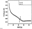
- FIG. 8 is an analysis result of negative electrode profiles of the batteries of Example 1 and Comparative example.
- the negative electrode profile was obtained by separately extracting the negative electrode profile (1.5C charge) at a time of charging through a three-electrode system and then differentiating a graph represented by a potential value with respect to SOC.
- A is a point at which a slope of the battery of Example 1 changed
- B is a point at which a slope of the battery of Comparative example changed.
- the battery according to Example 1 had an approximately 7% deeper depth of charge in comparison to the battery according to Comparative example, which means that lithium plating was suppressed.
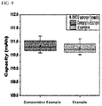
- FIG. 9 shows a result of measuring capacities of the batteries of Example 1 and Comparative example. According to FIG. 9 , the battery of Example 1 appeared to have nearly no lost capacity when compared with the battery of Comparative example.
- the electrode for a secondary battery of the present disclosure has nearly no loss of capacity when compared to a conventional electrode having no fine holes and allows the occurrence of the lithium plating phenomenon to be prevented despite a high loading amount of the electrode mixture layer, thereby allowing electrical performance deterioration of the electrode to be prevented.
Landscapes
- Chemical & Material Sciences (AREA)
- Engineering & Computer Science (AREA)
- Chemical Kinetics & Catalysis (AREA)
- Electrochemistry (AREA)
- General Chemical & Material Sciences (AREA)
- Manufacturing & Machinery (AREA)
- Materials Engineering (AREA)
- Composite Materials (AREA)
- Inorganic Chemistry (AREA)
- Battery Electrode And Active Subsutance (AREA)
Applications Claiming Priority (3)
| Application Number | Priority Date | Filing Date | Title |
|---|---|---|---|
| KR20160108048 | 2016-08-25 | ||
| KR1020170101381A KR102054326B1 (ko) | 2016-08-25 | 2017-08-10 | 미세 홀들을 포함하고 있는 이차전지용 전극 |
| PCT/KR2017/009079 WO2018038479A1 (ko) | 2016-08-25 | 2017-08-21 | 미세 홀들을 포함하고 있는 이차전지용 전극 |
Publications (3)
| Publication Number | Publication Date |
|---|---|
| EP3370280A1 true EP3370280A1 (de) | 2018-09-05 |
| EP3370280A4 EP3370280A4 (de) | 2018-12-05 |
| EP3370280B1 EP3370280B1 (de) | 2020-09-30 |
Family
ID=61689184
Family Applications (1)
| Application Number | Title | Priority Date | Filing Date |
|---|---|---|---|
| EP17843899.0A Active EP3370280B1 (de) | 2016-08-25 | 2017-08-21 | Elektrode für sekundärbatterie mit feinen löchern |
Country Status (4)
| Country | Link |
|---|---|
| US (1) | US10818929B2 (de) |
| EP (1) | EP3370280B1 (de) |
| KR (1) | KR102054326B1 (de) |
| CN (1) | CN108292737B (de) |
Cited By (4)
| Publication number | Priority date | Publication date | Assignee | Title |
|---|---|---|---|---|
| EP4057385A3 (de) * | 2021-03-09 | 2022-10-12 | Samsung Electronics Co., Ltd. | Elektrodenstruktur, sekundärbatterie damit und verfahren zur herstellung der elektrodenstruktur |
| EP4125144A3 (de) * | 2021-07-28 | 2023-03-15 | Samsung SDI Co., Ltd. | Elektrode, lithiumbatterie mit elektrode und herstellungsverfahren dafür |
| SE2350963A1 (en) * | 2023-08-15 | 2025-02-16 | Northvolt Ab | Secondary cell with a molded hybrid electrode |
| US12620573B2 (en) | 2021-07-28 | 2026-05-05 | Samsung Sdi Co., Ltd. | Electrode including electrode active material having through-holes, lithium battery containing the same, and method of preparing the same |
Families Citing this family (4)
| Publication number | Priority date | Publication date | Assignee | Title |
|---|---|---|---|---|
| KR102086783B1 (ko) | 2019-03-27 | 2020-03-09 | 광주과학기술원 | 리튬 이차 전지용 후막 전극 및 리튬 이차 전지 |
| US20210050599A1 (en) * | 2019-08-16 | 2021-02-18 | Samsung Sdi Co., Ltd. | High loading electrodes having high areal capacity and energy storage devices including the same |
| CN116190119A (zh) * | 2023-03-17 | 2023-05-30 | 广西大学 | 一种纳米多孔电极超级电容器的制备方法及其产品 |
| CN118943280B (zh) * | 2023-05-11 | 2026-03-20 | 宁德时代新能源科技股份有限公司 | 负极极片、二次电池和用电装置 |
Family Cites Families (21)
| Publication number | Priority date | Publication date | Assignee | Title |
|---|---|---|---|---|
| KR100274236B1 (ko) * | 1998-05-13 | 2001-02-01 | 김순택 | 리튬 이차 전지용 양극 활물질 및 그의 제조방법 |
| JP4183401B2 (ja) | 2001-06-28 | 2008-11-19 | 三洋電機株式会社 | リチウム二次電池用電極の製造方法及びリチウム二次電池 |
| JP2005285607A (ja) * | 2004-03-30 | 2005-10-13 | Matsushita Electric Ind Co Ltd | 非水系二次電池およびその製造方法 |
| KR100949332B1 (ko) * | 2007-08-24 | 2010-03-26 | 삼성에스디아이 주식회사 | 리튬 이차 전지용 전극 및 이를 포함하는 리튬 이차 전지 |
| CN101546649A (zh) * | 2008-03-28 | 2009-09-30 | 富士重工业株式会社 | 电极的制造方法、蓄电装置及中间层叠材料 |
| CN104183819A (zh) * | 2008-08-05 | 2014-12-03 | Sakti3有限公司 | 包含功能梯度部件的电化学电池 |
| EP2184798B1 (de) * | 2008-11-10 | 2021-02-17 | Samsung Electronics Co., Ltd. | Aktives Anodenmaterial, Anode mit dem aktiven Anodenmaterial, Lithiumbatterie mit der Anode und Verfahren zur Herstellung des aktiven Anodenmaterials |
| JP4672079B2 (ja) | 2009-01-14 | 2011-04-20 | パナソニック株式会社 | 非水系電池用負極板、非水系電池用電極群およびその製造方法、並びに、円筒形非水系二次電池およびその製造方法 |
| JP5572974B2 (ja) | 2009-03-24 | 2014-08-20 | セイコーエプソン株式会社 | 固体二次電池の製造方法 |
| US20130040188A1 (en) * | 2011-08-12 | 2013-02-14 | Fortu Intellectual Property Ag | Rechargeable electrochemical battery cell |
| JP2012190625A (ja) | 2011-03-10 | 2012-10-04 | Hitachi Ltd | 非水二次電池 |
| KR20140142576A (ko) | 2013-06-04 | 2014-12-12 | 주식회사 엘지화학 | 이차전지용 전극의 제조 방법 및 이로부터 제조된 전극을 포함하는 이차전지 |
| JP2015082421A (ja) | 2013-10-23 | 2015-04-27 | 日産自動車株式会社 | 電極、電池、電極の製造方法及び製造装置 |
| KR101664244B1 (ko) * | 2013-11-01 | 2016-10-10 | 주식회사 엘지화학 | 전극의 표면에 패턴을 형성하는 방법, 이 방법을 이용해 제조된 전극 및 이 전극을 포함하는 이차전지 |
| KR20150082958A (ko) | 2014-01-08 | 2015-07-16 | 주식회사 엘지화학 | 이차전지용 전극 및 그 제조방법 |
| US10122010B2 (en) | 2014-07-11 | 2018-11-06 | Semiconductor Energy Laboratory Co., Ltd. | Secondary battery and electronic device including the same |
| US9933090B2 (en) * | 2014-08-05 | 2018-04-03 | Air International, Inc. | Pipe retainer |
| KR20160024148A (ko) | 2014-08-25 | 2016-03-04 | 주식회사 엘지화학 | 표면에 미세 선형 홈을 포함하는 이차전지용 전극 |
| TW201622228A (zh) * | 2014-08-27 | 2016-06-16 | 應用材料股份有限公司 | 三維薄膜電池 |
| WO2016039264A1 (ja) * | 2014-09-10 | 2016-03-17 | 三菱マテリアル株式会社 | リチウムイオン二次電池用正極及びリチウムイオン二次電池 |
| JP5983821B2 (ja) | 2014-09-10 | 2016-09-06 | 三菱マテリアル株式会社 | リチウムイオン二次電池用正極及びリチウムイオン二次電池 |
-
2017
- 2017-08-10 KR KR1020170101381A patent/KR102054326B1/ko active Active
- 2017-08-21 EP EP17843899.0A patent/EP3370280B1/de active Active
- 2017-08-21 CN CN201780004280.5A patent/CN108292737B/zh active Active
- 2017-08-21 US US15/772,755 patent/US10818929B2/en active Active
Cited By (4)
| Publication number | Priority date | Publication date | Assignee | Title |
|---|---|---|---|---|
| EP4057385A3 (de) * | 2021-03-09 | 2022-10-12 | Samsung Electronics Co., Ltd. | Elektrodenstruktur, sekundärbatterie damit und verfahren zur herstellung der elektrodenstruktur |
| EP4125144A3 (de) * | 2021-07-28 | 2023-03-15 | Samsung SDI Co., Ltd. | Elektrode, lithiumbatterie mit elektrode und herstellungsverfahren dafür |
| US12620573B2 (en) | 2021-07-28 | 2026-05-05 | Samsung Sdi Co., Ltd. | Electrode including electrode active material having through-holes, lithium battery containing the same, and method of preparing the same |
| SE2350963A1 (en) * | 2023-08-15 | 2025-02-16 | Northvolt Ab | Secondary cell with a molded hybrid electrode |
Also Published As
| Publication number | Publication date |
|---|---|
| CN108292737A (zh) | 2018-07-17 |
| KR102054326B1 (ko) | 2019-12-11 |
| CN108292737B (zh) | 2021-01-15 |
| US10818929B2 (en) | 2020-10-27 |
| KR20180023822A (ko) | 2018-03-07 |
| EP3370280A4 (de) | 2018-12-05 |
| EP3370280B1 (de) | 2020-09-30 |
| US20190229341A1 (en) | 2019-07-25 |
Similar Documents
| Publication | Publication Date | Title |
|---|---|---|
| EP3370280B1 (de) | Elektrode für sekundärbatterie mit feinen löchern | |
| EP3553854B1 (de) | Lithium-ionen-batterie und negativelektrodenmaterial dafür | |
| KR101953757B1 (ko) | 음극활물질 및 이를 포함하는 이차전지 | |
| US9728816B2 (en) | Lithium-rich electrode sheet of lithium-ion battery and preparation method thereof | |
| EP4199135A1 (de) | Negativelektrodenplatte und sekundärbatterie | |
| EP4156343A1 (de) | Elektrodenplatte, zelle und batterie | |
| KR20090074175A (ko) | 이차전지 및 그 제조 방법 | |
| KR20180004678A (ko) | 음극 및 상기 음극을 포함하는 이차 전지 | |
| US20180026258A1 (en) | Method for making lithium ion battery electrode | |
| KR20160113981A (ko) | 음극 활물질 및 이의 제조방법 | |
| KR20180058333A (ko) | 전극 보호층을 포함하는 이차전지용 전극 | |
| CN118136918A (zh) | 一种二次电池和用电装置 | |
| KR20240146045A (ko) | 리튬 인산철 양극 활성 재료, 이의 제조 방법 및 리튬 이온 배터리 | |
| KR102495273B1 (ko) | 리튬 이차 전지용 전극, 리튬 이차 전지 및 리튬 이차 전지용 전극의 제조 방법 | |
| CN114678514B (zh) | 图案化锂金属、包含其的二次电池用电极和二次电池 | |
| CN219873595U (zh) | 负极片和电池 | |
| US9705135B2 (en) | Negative electrode for nonaqueous electrolyte secondary battery and nonaqueous electrolyte secondary battery | |
| CN114204038B (zh) | 集流体及其应用 | |
| KR20130136934A (ko) | 이차전지용 음극 활물질 | |
| WO2018038479A1 (ko) | 미세 홀들을 포함하고 있는 이차전지용 전극 | |
| KR20180021639A (ko) | 리튬 전극 및 이의 제조방법 | |
| KR20180076981A (ko) | 구조화된 표면 세퍼레이터를 갖는 리튬/금속 셀 | |
| CN119764338A (zh) | 一种负极片及其制备方法、应用 | |
| US9711783B2 (en) | Negative electrode for nonaqueous electrolyte secondary battery and nonaqueous electrolyte secondary battery | |
| EP4273995A1 (de) | Elektrodenanordnung mit kathode mit darin geformter isolierender überzugsschicht |
Legal Events
| Date | Code | Title | Description |
|---|---|---|---|
| STAA | Information on the status of an ep patent application or granted ep patent |
Free format text: STATUS: THE INTERNATIONAL PUBLICATION HAS BEEN MADE |
|
| PUAI | Public reference made under article 153(3) epc to a published international application that has entered the european phase |
Free format text: ORIGINAL CODE: 0009012 |
|
| STAA | Information on the status of an ep patent application or granted ep patent |
Free format text: STATUS: REQUEST FOR EXAMINATION WAS MADE |
|
| 17P | Request for examination filed |
Effective date: 20180528 |
|
| AK | Designated contracting states |
Kind code of ref document: A1 Designated state(s): AL AT BE BG CH CY CZ DE DK EE ES FI FR GB GR HR HU IE IS IT LI LT LU LV MC MK MT NL NO PL PT RO RS SE SI SK SM TR |
|
| AX | Request for extension of the european patent |
Extension state: BA ME |
|
| A4 | Supplementary search report drawn up and despatched |
Effective date: 20181026 |
|
| RIC1 | Information provided on ipc code assigned before grant |
Ipc: H01M 4/13 20100101AFI20181022BHEP Ipc: H01M 4/02 20060101ALI20181022BHEP Ipc: H01M 4/139 20100101ALI20181022BHEP Ipc: H01M 4/04 20060101ALI20181022BHEP Ipc: H01M 4/136 20100101ALI20181022BHEP |
|
| DAV | Request for validation of the european patent (deleted) | ||
| DAX | Request for extension of the european patent (deleted) | ||
| REG | Reference to a national code |
Ref country code: DE Ref legal event code: R079 Ref document number: 602017024790 Country of ref document: DE Free format text: PREVIOUS MAIN CLASS: H01M0004130000 Ipc: H01M0004139300 |
|
| RIC1 | Information provided on ipc code assigned before grant |
Ipc: H01M 4/1393 20100101AFI20200430BHEP Ipc: H01M 4/139 20100101ALI20200430BHEP Ipc: H01M 4/13 20100101ALI20200430BHEP Ipc: H01M 4/02 20060101ALI20200430BHEP Ipc: H01M 4/04 20060101ALI20200430BHEP |
|
| GRAP | Despatch of communication of intention to grant a patent |
Free format text: ORIGINAL CODE: EPIDOSNIGR1 |
|
| STAA | Information on the status of an ep patent application or granted ep patent |
Free format text: STATUS: GRANT OF PATENT IS INTENDED |
|
| INTG | Intention to grant announced |
Effective date: 20200617 |
|
| RIN1 | Information on inventor provided before grant (corrected) |
Inventor name: OH, SONG TAEK Inventor name: LEE, SOL NIP Inventor name: LEE, HYEOK MOO |
|
| GRAS | Grant fee paid |
Free format text: ORIGINAL CODE: EPIDOSNIGR3 |
|
| GRAA | (expected) grant |
Free format text: ORIGINAL CODE: 0009210 |
|
| STAA | Information on the status of an ep patent application or granted ep patent |
Free format text: STATUS: THE PATENT HAS BEEN GRANTED |
|
| AK | Designated contracting states |
Kind code of ref document: B1 Designated state(s): AL AT BE BG CH CY CZ DE DK EE ES FI FR GB GR HR HU IE IS IT LI LT LU LV MC MK MT NL NO PL PT RO RS SE SI SK SM TR |
|
| REG | Reference to a national code |
Ref country code: CH Ref legal event code: EP Ref country code: GB Ref legal event code: FG4D |
|
| REG | Reference to a national code |
Ref country code: AT Ref legal event code: REF Ref document number: 1319721 Country of ref document: AT Kind code of ref document: T Effective date: 20201015 |
|
| REG | Reference to a national code |
Ref country code: DE Ref legal event code: R096 Ref document number: 602017024790 Country of ref document: DE |
|
| REG | Reference to a national code |
Ref country code: IE Ref legal event code: FG4D |
|
| REG | Reference to a national code |
Ref country code: DE Ref legal event code: R081 Ref document number: 602017024790 Country of ref document: DE Owner name: LG ENERGY SOLUTION, LTD., KR Free format text: FORMER OWNER: LG CHEM. LTD., SEOUL, KR |
|
| PG25 | Lapsed in a contracting state [announced via postgrant information from national office to epo] |
Ref country code: GR Free format text: LAPSE BECAUSE OF FAILURE TO SUBMIT A TRANSLATION OF THE DESCRIPTION OR TO PAY THE FEE WITHIN THE PRESCRIBED TIME-LIMIT Effective date: 20201231 Ref country code: HR Free format text: LAPSE BECAUSE OF FAILURE TO SUBMIT A TRANSLATION OF THE DESCRIPTION OR TO PAY THE FEE WITHIN THE PRESCRIBED TIME-LIMIT Effective date: 20200930 Ref country code: NO Free format text: LAPSE BECAUSE OF FAILURE TO SUBMIT A TRANSLATION OF THE DESCRIPTION OR TO PAY THE FEE WITHIN THE PRESCRIBED TIME-LIMIT Effective date: 20201230 Ref country code: FI Free format text: LAPSE BECAUSE OF FAILURE TO SUBMIT A TRANSLATION OF THE DESCRIPTION OR TO PAY THE FEE WITHIN THE PRESCRIBED TIME-LIMIT Effective date: 20200930 Ref country code: SE Free format text: LAPSE BECAUSE OF FAILURE TO SUBMIT A TRANSLATION OF THE DESCRIPTION OR TO PAY THE FEE WITHIN THE PRESCRIBED TIME-LIMIT Effective date: 20200930 Ref country code: BG Free format text: LAPSE BECAUSE OF FAILURE TO SUBMIT A TRANSLATION OF THE DESCRIPTION OR TO PAY THE FEE WITHIN THE PRESCRIBED TIME-LIMIT Effective date: 20201230 |
|
| REG | Reference to a national code |
Ref country code: AT Ref legal event code: MK05 Ref document number: 1319721 Country of ref document: AT Kind code of ref document: T Effective date: 20200930 |
|
| PG25 | Lapsed in a contracting state [announced via postgrant information from national office to epo] |
Ref country code: LV Free format text: LAPSE BECAUSE OF FAILURE TO SUBMIT A TRANSLATION OF THE DESCRIPTION OR TO PAY THE FEE WITHIN THE PRESCRIBED TIME-LIMIT Effective date: 20200930 Ref country code: RS Free format text: LAPSE BECAUSE OF FAILURE TO SUBMIT A TRANSLATION OF THE DESCRIPTION OR TO PAY THE FEE WITHIN THE PRESCRIBED TIME-LIMIT Effective date: 20200930 |
|
| REG | Reference to a national code |
Ref country code: NL Ref legal event code: MP Effective date: 20200930 |
|
| REG | Reference to a national code |
Ref country code: LT Ref legal event code: MG4D |
|
| PG25 | Lapsed in a contracting state [announced via postgrant information from national office to epo] |
Ref country code: LT Free format text: LAPSE BECAUSE OF FAILURE TO SUBMIT A TRANSLATION OF THE DESCRIPTION OR TO PAY THE FEE WITHIN THE PRESCRIBED TIME-LIMIT Effective date: 20200930 Ref country code: SM Free format text: LAPSE BECAUSE OF FAILURE TO SUBMIT A TRANSLATION OF THE DESCRIPTION OR TO PAY THE FEE WITHIN THE PRESCRIBED TIME-LIMIT Effective date: 20200930 Ref country code: CZ Free format text: LAPSE BECAUSE OF FAILURE TO SUBMIT A TRANSLATION OF THE DESCRIPTION OR TO PAY THE FEE WITHIN THE PRESCRIBED TIME-LIMIT Effective date: 20200930 Ref country code: RO Free format text: LAPSE BECAUSE OF FAILURE TO SUBMIT A TRANSLATION OF THE DESCRIPTION OR TO PAY THE FEE WITHIN THE PRESCRIBED TIME-LIMIT Effective date: 20200930 Ref country code: PT Free format text: LAPSE BECAUSE OF FAILURE TO SUBMIT A TRANSLATION OF THE DESCRIPTION OR TO PAY THE FEE WITHIN THE PRESCRIBED TIME-LIMIT Effective date: 20210201 Ref country code: EE Free format text: LAPSE BECAUSE OF FAILURE TO SUBMIT A TRANSLATION OF THE DESCRIPTION OR TO PAY THE FEE WITHIN THE PRESCRIBED TIME-LIMIT Effective date: 20200930 |
|
| PG25 | Lapsed in a contracting state [announced via postgrant information from national office to epo] |
Ref country code: IS Free format text: LAPSE BECAUSE OF FAILURE TO SUBMIT A TRANSLATION OF THE DESCRIPTION OR TO PAY THE FEE WITHIN THE PRESCRIBED TIME-LIMIT Effective date: 20210130 Ref country code: AT Free format text: LAPSE BECAUSE OF FAILURE TO SUBMIT A TRANSLATION OF THE DESCRIPTION OR TO PAY THE FEE WITHIN THE PRESCRIBED TIME-LIMIT Effective date: 20200930 Ref country code: AL Free format text: LAPSE BECAUSE OF FAILURE TO SUBMIT A TRANSLATION OF THE DESCRIPTION OR TO PAY THE FEE WITHIN THE PRESCRIBED TIME-LIMIT Effective date: 20200930 Ref country code: ES Free format text: LAPSE BECAUSE OF FAILURE TO SUBMIT A TRANSLATION OF THE DESCRIPTION OR TO PAY THE FEE WITHIN THE PRESCRIBED TIME-LIMIT Effective date: 20200930 |
|
| PG25 | Lapsed in a contracting state [announced via postgrant information from national office to epo] |
Ref country code: NL Free format text: LAPSE BECAUSE OF FAILURE TO SUBMIT A TRANSLATION OF THE DESCRIPTION OR TO PAY THE FEE WITHIN THE PRESCRIBED TIME-LIMIT Effective date: 20200930 Ref country code: SK Free format text: LAPSE BECAUSE OF FAILURE TO SUBMIT A TRANSLATION OF THE DESCRIPTION OR TO PAY THE FEE WITHIN THE PRESCRIBED TIME-LIMIT Effective date: 20200930 |
|
| REG | Reference to a national code |
Ref country code: DE Ref legal event code: R097 Ref document number: 602017024790 Country of ref document: DE |
|
| PLBE | No opposition filed within time limit |
Free format text: ORIGINAL CODE: 0009261 |
|
| STAA | Information on the status of an ep patent application or granted ep patent |
Free format text: STATUS: NO OPPOSITION FILED WITHIN TIME LIMIT |
|
| PG25 | Lapsed in a contracting state [announced via postgrant information from national office to epo] |
Ref country code: DK Free format text: LAPSE BECAUSE OF FAILURE TO SUBMIT A TRANSLATION OF THE DESCRIPTION OR TO PAY THE FEE WITHIN THE PRESCRIBED TIME-LIMIT Effective date: 20200930 |
|
| 26N | No opposition filed |
Effective date: 20210701 |
|
| PG25 | Lapsed in a contracting state [announced via postgrant information from national office to epo] |
Ref country code: IT Free format text: LAPSE BECAUSE OF FAILURE TO SUBMIT A TRANSLATION OF THE DESCRIPTION OR TO PAY THE FEE WITHIN THE PRESCRIBED TIME-LIMIT Effective date: 20200930 |
|
| PG25 | Lapsed in a contracting state [announced via postgrant information from national office to epo] |
Ref country code: SI Free format text: LAPSE BECAUSE OF FAILURE TO SUBMIT A TRANSLATION OF THE DESCRIPTION OR TO PAY THE FEE WITHIN THE PRESCRIBED TIME-LIMIT Effective date: 20200930 |
|
| REG | Reference to a national code |
Ref country code: CH Ref legal event code: PL |
|
| PG25 | Lapsed in a contracting state [announced via postgrant information from national office to epo] |
Ref country code: MC Free format text: LAPSE BECAUSE OF FAILURE TO SUBMIT A TRANSLATION OF THE DESCRIPTION OR TO PAY THE FEE WITHIN THE PRESCRIBED TIME-LIMIT Effective date: 20200930 |
|
| REG | Reference to a national code |
Ref country code: BE Ref legal event code: MM Effective date: 20210831 |
|
| PG25 | Lapsed in a contracting state [announced via postgrant information from national office to epo] |
Ref country code: LI Free format text: LAPSE BECAUSE OF NON-PAYMENT OF DUE FEES Effective date: 20210831 Ref country code: CH Free format text: LAPSE BECAUSE OF NON-PAYMENT OF DUE FEES Effective date: 20210831 |
|
| PG25 | Lapsed in a contracting state [announced via postgrant information from national office to epo] |
Ref country code: IS Free format text: LAPSE BECAUSE OF FAILURE TO SUBMIT A TRANSLATION OF THE DESCRIPTION OR TO PAY THE FEE WITHIN THE PRESCRIBED TIME-LIMIT Effective date: 20210130 Ref country code: LU Free format text: LAPSE BECAUSE OF NON-PAYMENT OF DUE FEES Effective date: 20210821 |
|
| PG25 | Lapsed in a contracting state [announced via postgrant information from national office to epo] |
Ref country code: IE Free format text: LAPSE BECAUSE OF NON-PAYMENT OF DUE FEES Effective date: 20210821 Ref country code: BE Free format text: LAPSE BECAUSE OF NON-PAYMENT OF DUE FEES Effective date: 20210831 |
|
| P01 | Opt-out of the competence of the unified patent court (upc) registered |
Effective date: 20230512 |
|
| PG25 | Lapsed in a contracting state [announced via postgrant information from national office to epo] |
Ref country code: CY Free format text: LAPSE BECAUSE OF FAILURE TO SUBMIT A TRANSLATION OF THE DESCRIPTION OR TO PAY THE FEE WITHIN THE PRESCRIBED TIME-LIMIT Effective date: 20200930 |
|
| PG25 | Lapsed in a contracting state [announced via postgrant information from national office to epo] |
Ref country code: HU Free format text: LAPSE BECAUSE OF FAILURE TO SUBMIT A TRANSLATION OF THE DESCRIPTION OR TO PAY THE FEE WITHIN THE PRESCRIBED TIME-LIMIT; INVALID AB INITIO Effective date: 20170821 |
|
| REG | Reference to a national code |
Ref country code: GB Ref legal event code: 732E Free format text: REGISTERED BETWEEN 20230824 AND 20230831 |
|
| REG | Reference to a national code |
Ref country code: DE Ref legal event code: R081 Ref document number: 602017024790 Country of ref document: DE Owner name: LG ENERGY SOLUTION, LTD., KR Free format text: FORMER OWNER: LG CHEM, LTD., SEOUL, KR |
|
| PG25 | Lapsed in a contracting state [announced via postgrant information from national office to epo] |
Ref country code: MK Free format text: LAPSE BECAUSE OF FAILURE TO SUBMIT A TRANSLATION OF THE DESCRIPTION OR TO PAY THE FEE WITHIN THE PRESCRIBED TIME-LIMIT Effective date: 20200930 |
|
| PG25 | Lapsed in a contracting state [announced via postgrant information from national office to epo] |
Ref country code: TR Free format text: LAPSE BECAUSE OF FAILURE TO SUBMIT A TRANSLATION OF THE DESCRIPTION OR TO PAY THE FEE WITHIN THE PRESCRIBED TIME-LIMIT Effective date: 20200930 |
|
| PG25 | Lapsed in a contracting state [announced via postgrant information from national office to epo] |
Ref country code: MT Free format text: LAPSE BECAUSE OF FAILURE TO SUBMIT A TRANSLATION OF THE DESCRIPTION OR TO PAY THE FEE WITHIN THE PRESCRIBED TIME-LIMIT Effective date: 20200930 |
|
| PGFP | Annual fee paid to national office [announced via postgrant information from national office to epo] |
Ref country code: DE Payment date: 20250721 Year of fee payment: 9 |
|
| PGFP | Annual fee paid to national office [announced via postgrant information from national office to epo] |
Ref country code: PL Payment date: 20250723 Year of fee payment: 9 |
|
| PGFP | Annual fee paid to national office [announced via postgrant information from national office to epo] |
Ref country code: GB Payment date: 20250722 Year of fee payment: 9 |
|
| PGFP | Annual fee paid to national office [announced via postgrant information from national office to epo] |
Ref country code: FR Payment date: 20250725 Year of fee payment: 9 |