EP3369949B1 - Anschlagpunkt oder zurrpunkt mit magnet - Google Patents
Anschlagpunkt oder zurrpunkt mit magnet Download PDFInfo
- Publication number
- EP3369949B1 EP3369949B1 EP18159479.7A EP18159479A EP3369949B1 EP 3369949 B1 EP3369949 B1 EP 3369949B1 EP 18159479 A EP18159479 A EP 18159479A EP 3369949 B1 EP3369949 B1 EP 3369949B1
- Authority
- EP
- European Patent Office
- Prior art keywords
- magnet
- point
- lashing
- eyelet body
- eyelet
- Prior art date
- Legal status (The legal status is an assumption and is not a legal conclusion. Google has not performed a legal analysis and makes no representation as to the accuracy of the status listed.)
- Not-in-force
Links
Images


Classifications
-
- F—MECHANICAL ENGINEERING; LIGHTING; HEATING; WEAPONS; BLASTING
- F16—ENGINEERING ELEMENTS AND UNITS; GENERAL MEASURES FOR PRODUCING AND MAINTAINING EFFECTIVE FUNCTIONING OF MACHINES OR INSTALLATIONS; THERMAL INSULATION IN GENERAL
- F16B—DEVICES FOR FASTENING OR SECURING CONSTRUCTIONAL ELEMENTS OR MACHINE PARTS TOGETHER, e.g. NAILS, BOLTS, CIRCLIPS, CLAMPS, CLIPS OR WEDGES; JOINTS OR JOINTING
- F16B45/00—Hooks; Eyes
- F16B45/002—Eyes
-
- B—PERFORMING OPERATIONS; TRANSPORTING
- B60—VEHICLES IN GENERAL
- B60P—VEHICLES ADAPTED FOR LOAD TRANSPORTATION OR TO TRANSPORT, TO CARRY, OR TO COMPRISE SPECIAL LOADS OR OBJECTS
- B60P7/00—Securing or covering of load on vehicles
- B60P7/06—Securing of load
- B60P7/08—Securing to the vehicle floor or sides
- B60P7/0807—Attachment points
-
- F—MECHANICAL ENGINEERING; LIGHTING; HEATING; WEAPONS; BLASTING
- F16—ENGINEERING ELEMENTS AND UNITS; GENERAL MEASURES FOR PRODUCING AND MAINTAINING EFFECTIVE FUNCTIONING OF MACHINES OR INSTALLATIONS; THERMAL INSULATION IN GENERAL
- F16B—DEVICES FOR FASTENING OR SECURING CONSTRUCTIONAL ELEMENTS OR MACHINE PARTS TOGETHER, e.g. NAILS, BOLTS, CIRCLIPS, CLAMPS, CLIPS OR WEDGES; JOINTS OR JOINTING
- F16B45/00—Hooks; Eyes
- F16B45/005—Hooks; Eyes characterised by the material
-
- F—MECHANICAL ENGINEERING; LIGHTING; HEATING; WEAPONS; BLASTING
- F16—ENGINEERING ELEMENTS AND UNITS; GENERAL MEASURES FOR PRODUCING AND MAINTAINING EFFECTIVE FUNCTIONING OF MACHINES OR INSTALLATIONS; THERMAL INSULATION IN GENERAL
- F16B—DEVICES FOR FASTENING OR SECURING CONSTRUCTIONAL ELEMENTS OR MACHINE PARTS TOGETHER, e.g. NAILS, BOLTS, CIRCLIPS, CLAMPS, CLIPS OR WEDGES; JOINTS OR JOINTING
- F16B2200/00—Constructional details of connections not covered for in other groups of this subclass
- F16B2200/83—Use of a magnetic material
Definitions
- the present invention relates to an attachment point or lashing point according to the features in the preamble of claim 1.
- attachment points or lashing points known from the prior art are usually in a rest position arranged. They can be moved from the rest position into a use position.
- An eyelet body of an attachment point or lashing point has a weight of several hundred grams or even kilograms.
- the eyelet body is usually made of a steel material, but at least of a light metal material. If it lies on an object or surface in the rest position, or is sunk in a rest position, it can lead to disturbing noise when not in use. The rest position can also be left in an uncontrolled and unwanted manner.
- the attachment point or lashing point is attached to an object or on a surface.
- the attachment point or lashing point is coupled with a lifting, pulling or lashing device.
- a hook is hooked in or a lashing strap or a fastening chain is pulled through.
- the attachment point or lashing point has an eyelet body.
- the eyelet body is designed as a circumferentially closed eyelet.
- the eyelet can be U-shaped or be oval. However, the eyelet can also be ring-shaped or circular.
- the eyelet body is coupled to the object by incorporating a base body.
- the base body is in particular firmly coupled to the object.
- the base body can be, for example, weld-in sleeves or also a weld-in cassette.
- the base body can also be designed as a bow body.
- the base body can also be coupled to the object in a form-fitting manner, for example by a screw connection.
- the eyelet body is then mounted so as to be relatively movable with respect to the base body.
- the eyelet body is, in particular, pivotable with respect to the base body and thus also with respect to the object or the base.
- the eyelet body can take at least one rest position. This is preferably either lying on the underground of the object or is sunk in or with the base body relative to the underground of the object.
- the eyelet body can now be brought into a use position from the rest position.
- the attachment point or lashing point is characterized in that at least one magnet is introduced into the eyelet body, in such a way that the magnet holds the eyelet body with its magnetic force in the rest position or use position on the object or on a base and / or on the base body.
- the magnet is introduced into the eyelet body itself, preferably sunk in relation to the eyelet body. If the eyelet body lies, for example, on the base of the object, the magnet exerts a magnetic force on the base and holds the eyelet body firmly on the base. This prevents rattling. At the same time it is avoided that the eyelet body is inadvertently moved out of this rest position. The magnetic force is only overcome and the eyelet body is brought out of the rest position into the use position only when a force level is exceeded, for example by the hand of an assembler taking up the eyelet body.
- the object or base is preferably formed from steel material. If the object or base is not magnetic, it is further provided within the scope of the invention to introduce corresponding magnets and / or metal bodies here, so that the eyelet body is held in the rest position.
- raw magnets are used. These are provided as cylinders or rectangular bodies. The magnets are then inserted into the eyelet body. For this purpose, in the case of a cylinder, in particular a bore, for example a blind hole or a milling, can be carried out. The magnet itself is then preferably glued in the recess. For this purpose, a two-component adhesive is particularly preferably used.
- the magnet is held alternatively or additionally frictionally and / or positively.
- the magnet in particular can be pressed into the recess in the eyelet body.
- the eyelet body has two lateral, opposite legs.
- a magnet is preferably arranged in at least one leg on one side.
- a magnet is arranged in at least one leg and on each side.
- an eyelet body can thus assume two opposite rest positions.
- the eyelet body can be placed on its back.
- the eyelet body can also be swiveled by approx. 180 ° and placed on its front.
- a magnet is provided in each leg on each side.
- at least two magnets are provided on the front and at least two magnets on the back, which then hold the eyelet body in the rest position by means of magnetic force in the respective rest position.
- a respective magnet is particularly preferably recessed in the eyelet body in such a way that it terminates essentially flat or even with an edge surface surrounding the magnet.
- the magnet does not protrude from the surface in question. At least, however, the magnet is arranged sunk so that it does not protrude from a front or back of the eyelet body.
- the eyelet body has laterally projecting legs.
- a magnet can then preferably also be arranged in one leg.
- the eyelet body is preferably mounted recessed in a base body.
- the base body is particularly preferably a cassette. If the eyelet body is sunk into the base body, then in the rest position the legs rest on an underside of the cassette, in particular on an underside of a guide in the cassette, and are held here by a magnet.
- the magnet can be positioned in such a way that when the eyelet body is brought into a position of use, the magnet also lies in a guide on the cassette and the position of use assumed is additionally fixed in position.
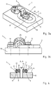
- Figure 1 shows an attachment point or lashing point 1 according to the invention.
- This has an eyelet body 2 and a base body 3.
- the base body 3 is designed here as a weld-on tab and can be coupled to the base 4 via a material connection (not shown in more detail).
- the base body 3 itself has an opening in which the eyelet body 2 is arranged. The opening can also result between the base body 3 and a base 4 on which the base body 3 is fastened.
- the eyelet body 2 is pivotable, as in Figure 1 and 2 each shown in the rest position. It is, however, mounted on the base body 3 in the pivoting direction 5 so that it can be pivoted through 180 °. In the rest position, a front side 6 of the eyelet body 2 shown here lies on the base 4.
- a magnet 9 is arranged in both legs 7 of the eyelet body 2 on the front 6 and the rear 8.
- the magnets 9 are arranged sunk in relation to the front 6 or rear 8, in such a way that the front 6 or rear 8 is flat or planar.
- the magnet 9 does not protrude from the contour of the front side 6 and cannot lead to the lashing strap getting caught here.
- the magnet 9 is in each case recessed in a receptacle 10 and, as shown here, glued into the receptacle 10.
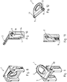
- Figure 3a and 3b and FIG. 4 show a further embodiment variant of an attachment point or lashing point 1 according to the invention.
- Figure 3a shows a perspective view and Figure 3b a side view.
- Figure 4 shows a sectional view along the section line AA.
- the attachment point or lashing point 1 is fastened to a base 4 of an object 19.
- a base body 3 in the form of a bracket is screwed to the base 4 via two screw bolts 11.
- the eyelet body 2 is in turn pivotally mounted on the base body 3.
- magnets 9 are arranged on the front 6 and rear 8 of each leg 7.
- the eyelet body 2 is made of a round steel.
- the outer side 12 of the magnet 9 can preferably be adapted to the outer contour of the front side 6 or rear side 8 in a continuous manner. In this case, the outside 12 of the respective magnet 9 would be rounded. Here too there is an essentially smooth or seamless Surface without the magnet 9 protruding from the surface or being countersunk relative to the surface. If the eyelet body 2 is raised from the base 4, the magnetic force exerted is overcome and the eyelet body 2 can be pivoted into the use position. In the rest position, a distance or play 25 can be formed in particular between the base body 3 and the eyelet body 2. Because the eyelet body 2 is held on the base 4 by the magnets 9, there are no rattling noises and also no uncontrolled movement or movement of the eyelet body 2 not required in the base body 3.
- Figure 5 to 7 show a third embodiment variant of the attachment point or lashing point 1 according to the invention.
- an eyelet body 2 is provided, which is coupled to the ground via a two-part base body 3, which is arranged laterally.
- the base body 3 are preferably welded to the base 4 via a thermal joining seam, not shown.
- the eyelet body 2 has laterally projecting legs 7, a respective leg 13 engaging in the base body 3.
- a magnet 9 is arranged on a front side 6 and on a rear side 8, in such a way that, in a rest position, the magnets 9 on one side, ie front side 6 and rear side 8, rest on the base 4 and the eyelet body 2 hold in the rest position due to the magnetic force.
- Figures 8 to 12 show a further embodiment variant of a lifting point or lashing point 1.
- a lashing point is from the DE 20 2015 100 750 U1 known.
- magnets 9 are inserted on an underside of the laterally projecting legs.
- FIGs 8 and 11 shown rest position of the respective magnet 9 on an underside 16 of the link 17 and here hold the eyelet body 2 in the sunken rest position in addition to its weight by magnetic force.
- the magnet 9 according to Figures 9 and 10 rest in the use position on an inside 18 of the link 17 and are therefore held in the use position by the magnet 9 due to the magnetic force in addition to the support due to the weight.
- Figure 13 to 16 show a further variant of a stop or lashing point 1 in different views.
- an eyelet body 2 is formed with laterally projecting legs 13.
- the eyelet body 2 is mounted in a base body 3 in the form of a cassette, in particular a welded-in cassette. For this purpose, it can be brought into a rest position (not shown) via a backdrop 17 or as in FIG Figures 13, 14 and 15 shown to be held in a position of use. In the use position, the eyelet body 2 projects beyond the base body 3 and is also pivotably mounted in the base body 3.
- a rear side 8 of the eyelet body 2 is supported on a rear wall 20 of the base body 3.
- part 21 of rear wall 20 projects over an upper side 22.
- the part 21 is arranged at an angle ⁇ at an angle to the wall 20, so that the eyelet body 2 is also supported at an angle in the use position.
- the rear side 8 of the eyelet body 2 is supported on an end face 23 of the wall 20.
- magnets 9 are inserted into the eyelet body 2, so that the magnets 9 hold the eyelet body 2 supported in the use position with a magnetic force.
- the eyelet body 2 can also be supported in the use position due to its weight.
- magnets 9 can also be used, which in particular in a Figure 11 shown rest position keep the eyelet body 2 sunk in the cassette.
- the base body 3 in the form of the cassette according to Figure 15 is formed by the rear wall 20 and two side welding plates 24, in which the scenes 17 are arranged.
Landscapes
- Engineering & Computer Science (AREA)
- General Engineering & Computer Science (AREA)
- Mechanical Engineering (AREA)
- Transportation (AREA)
- Fittings On The Vehicle Exterior For Carrying Loads, And Devices For Holding Or Mounting Articles (AREA)
- Hooks, Suction Cups, And Attachment By Adhesive Means (AREA)
Priority Applications (1)
| Application Number | Priority Date | Filing Date | Title |
|---|---|---|---|
| PL18159479T PL3369949T3 (pl) | 2017-03-03 | 2018-03-01 | Punkt kotwienia lub punkt mocowania lin mający magnes |
Applications Claiming Priority (1)
| Application Number | Priority Date | Filing Date | Title |
|---|---|---|---|
| DE202017101234.4U DE202017101234U1 (de) | 2017-03-03 | 2017-03-03 | Anschlagpunkt oder Zurrpunkt mit Magnet |
Publications (2)
| Publication Number | Publication Date |
|---|---|
| EP3369949A1 EP3369949A1 (de) | 2018-09-05 |
| EP3369949B1 true EP3369949B1 (de) | 2020-04-22 |
Family
ID=61563160
Family Applications (1)
| Application Number | Title | Priority Date | Filing Date |
|---|---|---|---|
| EP18159479.7A Not-in-force EP3369949B1 (de) | 2017-03-03 | 2018-03-01 | Anschlagpunkt oder zurrpunkt mit magnet |
Country Status (3)
| Country | Link |
|---|---|
| EP (1) | EP3369949B1 (pl) |
| DE (1) | DE202017101234U1 (pl) |
| PL (1) | PL3369949T3 (pl) |
Cited By (1)
| Publication number | Priority date | Publication date | Assignee | Title |
|---|---|---|---|---|
| EP3912859A1 (de) * | 2020-05-18 | 2021-11-24 | Thiele GmbH & Co. KG | Zurrkassettenmodul |
Families Citing this family (2)
| Publication number | Priority date | Publication date | Assignee | Title |
|---|---|---|---|---|
| DE202019101641U1 (de) * | 2019-03-21 | 2020-06-23 | Thiele Gmbh & Co. Kg | Zurrpunkt mit Montagestellung |
| DE102023001801A1 (de) * | 2023-05-04 | 2024-11-07 | PohlCon GmbH | Lastaufnahmevorrichtung, insbesondere für den Aufzugsbau |
Family Cites Families (9)
| Publication number | Priority date | Publication date | Assignee | Title |
|---|---|---|---|---|
| DE29500242U1 (de) * | 1995-01-09 | 1996-05-09 | Plogmann, Kurt, 49082 Osnabrück | Verzurrhalterung an einem Lastkraftwagen |
| JP2001221375A (ja) * | 1995-10-03 | 2001-08-17 | Hitachi Metals Ltd | 磁気式吊り装置 |
| DE10311805B4 (de) * | 2003-03-12 | 2008-06-26 | Bos Gmbh & Co. Kg | Arretierungsvorrichtung für Aufnahmemodul |
| DE20313685U1 (de) * | 2003-09-01 | 2003-10-30 | Barthau Anhängerbau GmbH, 74547 Untermünkheim | Fahrzeug mit Ladeboden |
| US20130322981A1 (en) * | 2011-07-02 | 2013-12-05 | Sta-Put-Hook, Llc | Tie Down Strap Hook |
| DE202013005581U1 (de) * | 2013-06-21 | 2014-09-22 | Illinois Tool Works Inc. | Vorrichtung zum Befestigen von Gegenständen in einem Gepäck- oder Laderaum eines Kraftfahrzeugs |
| US9345312B1 (en) * | 2015-02-06 | 2016-05-24 | Gregory Washio | Mobile device transportation apparatus |
| DE202015100750U1 (de) | 2015-02-17 | 2015-03-03 | Thiele Gmbh & Co. Kg | Zurrpunkt |
| DE202015100857U1 (de) | 2015-02-23 | 2015-03-04 | Thiele Gmbh & Co. Kg | Anschlagpunkt mit Fixierscheibe |
-
2017
- 2017-03-03 DE DE202017101234.4U patent/DE202017101234U1/de not_active Expired - Lifetime
-
2018
- 2018-03-01 EP EP18159479.7A patent/EP3369949B1/de not_active Not-in-force
- 2018-03-01 PL PL18159479T patent/PL3369949T3/pl unknown
Non-Patent Citations (1)
| Title |
|---|
| None * |
Cited By (1)
| Publication number | Priority date | Publication date | Assignee | Title |
|---|---|---|---|---|
| EP3912859A1 (de) * | 2020-05-18 | 2021-11-24 | Thiele GmbH & Co. KG | Zurrkassettenmodul |
Also Published As
| Publication number | Publication date |
|---|---|
| EP3369949A1 (de) | 2018-09-05 |
| PL3369949T3 (pl) | 2020-11-30 |
| DE202017101234U1 (de) | 2018-06-05 |
Similar Documents
| Publication | Publication Date | Title |
|---|---|---|
| EP3369949B1 (de) | Anschlagpunkt oder zurrpunkt mit magnet | |
| DE102020102042A1 (de) | Truck-heckklappe mit fangband | |
| EP3115254B1 (de) | Zurreinrichtung | |
| EP3000655B1 (de) | Vorrichtung zum festlegen von ladungsgegenständen | |
| EP2698296A2 (de) | Längenverstellbares Teleskoprohr | |
| EP3037325B1 (de) | Verwindungssteifer und montagefreundlicher montagerahmen für ein lastentransportfahrzeug | |
| DE202016004557U1 (de) | Ladungssicherungs-Abdeckvorrichtung für landwirtschaftliche Transportwagen | |
| DE202010011440U1 (de) | Vorrichtung zum Sichern von Ladung auf einer Ladefläche eines Fahrzeugaufbaus | |
| DE2048373A1 (de) | Bewegliches Fahrzeugdach | |
| DE102015216998A1 (de) | Verriegelungseinrichtung zum Sichern und Verriegeln eines Behälters und Lastentransportfahrzeug | |
| DE202015100857U1 (de) | Anschlagpunkt mit Fixierscheibe | |
| EP2080729B1 (de) | Ladekran mit in Transportstellung bringbarem Lastaufnahmemittel | |
| EP3015311B1 (de) | Nutzfahrzeugaufbau und Verfahren zum Sichern der Lage eines Transportguts auf einer Ladefläche eines Nutzfahrzeugs | |
| DE202017104826U1 (de) | Zurrpunkt mit Magnetarretierung | |
| EP2428397B1 (de) | Lochprofilschiene | |
| DE102010023885A1 (de) | Vorrichtung zur Festlegung von Ladungssicherungselementen | |
| DE102012108359B4 (de) | Nutzfahrzeug | |
| DE102005042288A1 (de) | Abdeckung für die Ladekante eines Kraftfahrzeuges und Kraftfahrzeug mit einer solchen Abdeckung | |
| DE10322569B4 (de) | Verzurrhalterung zur Anbringung an einem Träger | |
| DE202013000332U1 (de) | Kraftfahrzeug mit Laderaum, beladbar in zwei Beladestellungen | |
| DE202017004635U1 (de) | Mit versenkbarer Zurröse kombinierbarer Rungenfuß | |
| DE102017104484B4 (de) | Zurrpunkt mit Einschweißkassette | |
| EP1847447A1 (de) | Runge für die Ladeöffnung eines Fahrzeugaufbaus | |
| DE202009009270U1 (de) | Fahrzeug und Zurrelement | |
| EP3546260A1 (de) | Planenverschlusselement, plane und fahrzeugaufbau |
Legal Events
| Date | Code | Title | Description |
|---|---|---|---|
| PUAI | Public reference made under article 153(3) epc to a published international application that has entered the european phase |
Free format text: ORIGINAL CODE: 0009012 |
|
| STAA | Information on the status of an ep patent application or granted ep patent |
Free format text: STATUS: THE APPLICATION HAS BEEN PUBLISHED |
|
| STAA | Information on the status of an ep patent application or granted ep patent |
Free format text: STATUS: REQUEST FOR EXAMINATION WAS MADE |
|
| AK | Designated contracting states |
Kind code of ref document: A1 Designated state(s): AL AT BE BG CH CY CZ DE DK EE ES FI FR GB GR HR HU IE IS IT LI LT LU LV MC MK MT NL NO PL PT RO RS SE SI SK SM TR |
|
| AX | Request for extension of the european patent |
Extension state: BA ME |
|
| 17P | Request for examination filed |
Effective date: 20180809 |
|
| GRAP | Despatch of communication of intention to grant a patent |
Free format text: ORIGINAL CODE: EPIDOSNIGR1 |
|
| STAA | Information on the status of an ep patent application or granted ep patent |
Free format text: STATUS: GRANT OF PATENT IS INTENDED |
|
| INTG | Intention to grant announced |
Effective date: 20191205 |
|
| RIN1 | Information on inventor provided before grant (corrected) |
Inventor name: NORPOTH, BERNHARD |
|
| GRAS | Grant fee paid |
Free format text: ORIGINAL CODE: EPIDOSNIGR3 |
|
| GRAA | (expected) grant |
Free format text: ORIGINAL CODE: 0009210 |
|
| STAA | Information on the status of an ep patent application or granted ep patent |
Free format text: STATUS: THE PATENT HAS BEEN GRANTED |
|
| AK | Designated contracting states |
Kind code of ref document: B1 Designated state(s): AL AT BE BG CH CY CZ DE DK EE ES FI FR GB GR HR HU IE IS IT LI LT LU LV MC MK MT NL NO PL PT RO RS SE SI SK SM TR |
|
| REG | Reference to a national code |
Ref country code: CH Ref legal event code: EP |
|
| REG | Reference to a national code |
Ref country code: DE Ref legal event code: R096 Ref document number: 502018001234 Country of ref document: DE |
|
| REG | Reference to a national code |
Ref country code: IE Ref legal event code: FG4D Free format text: LANGUAGE OF EP DOCUMENT: GERMAN |
|
| REG | Reference to a national code |
Ref country code: AT Ref legal event code: REF Ref document number: 1260496 Country of ref document: AT Kind code of ref document: T Effective date: 20200515 |
|
| REG | Reference to a national code |
Ref country code: LT Ref legal event code: MG4D |
|
| REG | Reference to a national code |
Ref country code: NL Ref legal event code: MP Effective date: 20200422 |
|
| PG25 | Lapsed in a contracting state [announced via postgrant information from national office to epo] |
Ref country code: LT Free format text: LAPSE BECAUSE OF FAILURE TO SUBMIT A TRANSLATION OF THE DESCRIPTION OR TO PAY THE FEE WITHIN THE PRESCRIBED TIME-LIMIT Effective date: 20200422 Ref country code: PT Free format text: LAPSE BECAUSE OF FAILURE TO SUBMIT A TRANSLATION OF THE DESCRIPTION OR TO PAY THE FEE WITHIN THE PRESCRIBED TIME-LIMIT Effective date: 20200824 Ref country code: GR Free format text: LAPSE BECAUSE OF FAILURE TO SUBMIT A TRANSLATION OF THE DESCRIPTION OR TO PAY THE FEE WITHIN THE PRESCRIBED TIME-LIMIT Effective date: 20200723 Ref country code: NO Free format text: LAPSE BECAUSE OF FAILURE TO SUBMIT A TRANSLATION OF THE DESCRIPTION OR TO PAY THE FEE WITHIN THE PRESCRIBED TIME-LIMIT Effective date: 20200722 Ref country code: NL Free format text: LAPSE BECAUSE OF FAILURE TO SUBMIT A TRANSLATION OF THE DESCRIPTION OR TO PAY THE FEE WITHIN THE PRESCRIBED TIME-LIMIT Effective date: 20200422 Ref country code: IS Free format text: LAPSE BECAUSE OF FAILURE TO SUBMIT A TRANSLATION OF THE DESCRIPTION OR TO PAY THE FEE WITHIN THE PRESCRIBED TIME-LIMIT Effective date: 20200822 Ref country code: SE Free format text: LAPSE BECAUSE OF FAILURE TO SUBMIT A TRANSLATION OF THE DESCRIPTION OR TO PAY THE FEE WITHIN THE PRESCRIBED TIME-LIMIT Effective date: 20200422 Ref country code: FI Free format text: LAPSE BECAUSE OF FAILURE TO SUBMIT A TRANSLATION OF THE DESCRIPTION OR TO PAY THE FEE WITHIN THE PRESCRIBED TIME-LIMIT Effective date: 20200422 |
|
| PG25 | Lapsed in a contracting state [announced via postgrant information from national office to epo] |
Ref country code: RS Free format text: LAPSE BECAUSE OF FAILURE TO SUBMIT A TRANSLATION OF THE DESCRIPTION OR TO PAY THE FEE WITHIN THE PRESCRIBED TIME-LIMIT Effective date: 20200422 Ref country code: HR Free format text: LAPSE BECAUSE OF FAILURE TO SUBMIT A TRANSLATION OF THE DESCRIPTION OR TO PAY THE FEE WITHIN THE PRESCRIBED TIME-LIMIT Effective date: 20200422 Ref country code: LV Free format text: LAPSE BECAUSE OF FAILURE TO SUBMIT A TRANSLATION OF THE DESCRIPTION OR TO PAY THE FEE WITHIN THE PRESCRIBED TIME-LIMIT Effective date: 20200422 Ref country code: BG Free format text: LAPSE BECAUSE OF FAILURE TO SUBMIT A TRANSLATION OF THE DESCRIPTION OR TO PAY THE FEE WITHIN THE PRESCRIBED TIME-LIMIT Effective date: 20200722 |
|
| PG25 | Lapsed in a contracting state [announced via postgrant information from national office to epo] |
Ref country code: AL Free format text: LAPSE BECAUSE OF FAILURE TO SUBMIT A TRANSLATION OF THE DESCRIPTION OR TO PAY THE FEE WITHIN THE PRESCRIBED TIME-LIMIT Effective date: 20200422 |
|
| REG | Reference to a national code |
Ref country code: DE Ref legal event code: R097 Ref document number: 502018001234 Country of ref document: DE |
|
| PG25 | Lapsed in a contracting state [announced via postgrant information from national office to epo] |
Ref country code: CZ Free format text: LAPSE BECAUSE OF FAILURE TO SUBMIT A TRANSLATION OF THE DESCRIPTION OR TO PAY THE FEE WITHIN THE PRESCRIBED TIME-LIMIT Effective date: 20200422 Ref country code: RO Free format text: LAPSE BECAUSE OF FAILURE TO SUBMIT A TRANSLATION OF THE DESCRIPTION OR TO PAY THE FEE WITHIN THE PRESCRIBED TIME-LIMIT Effective date: 20200422 Ref country code: ES Free format text: LAPSE BECAUSE OF FAILURE TO SUBMIT A TRANSLATION OF THE DESCRIPTION OR TO PAY THE FEE WITHIN THE PRESCRIBED TIME-LIMIT Effective date: 20200422 Ref country code: EE Free format text: LAPSE BECAUSE OF FAILURE TO SUBMIT A TRANSLATION OF THE DESCRIPTION OR TO PAY THE FEE WITHIN THE PRESCRIBED TIME-LIMIT Effective date: 20200422 Ref country code: SM Free format text: LAPSE BECAUSE OF FAILURE TO SUBMIT A TRANSLATION OF THE DESCRIPTION OR TO PAY THE FEE WITHIN THE PRESCRIBED TIME-LIMIT Effective date: 20200422 Ref country code: DK Free format text: LAPSE BECAUSE OF FAILURE TO SUBMIT A TRANSLATION OF THE DESCRIPTION OR TO PAY THE FEE WITHIN THE PRESCRIBED TIME-LIMIT Effective date: 20200422 Ref country code: IT Free format text: LAPSE BECAUSE OF FAILURE TO SUBMIT A TRANSLATION OF THE DESCRIPTION OR TO PAY THE FEE WITHIN THE PRESCRIBED TIME-LIMIT Effective date: 20200422 |
|
| PG25 | Lapsed in a contracting state [announced via postgrant information from national office to epo] |
Ref country code: SK Free format text: LAPSE BECAUSE OF FAILURE TO SUBMIT A TRANSLATION OF THE DESCRIPTION OR TO PAY THE FEE WITHIN THE PRESCRIBED TIME-LIMIT Effective date: 20200422 |
|
| PLBE | No opposition filed within time limit |
Free format text: ORIGINAL CODE: 0009261 |
|
| STAA | Information on the status of an ep patent application or granted ep patent |
Free format text: STATUS: NO OPPOSITION FILED WITHIN TIME LIMIT |
|
| 26N | No opposition filed |
Effective date: 20210125 |
|
| PG25 | Lapsed in a contracting state [announced via postgrant information from national office to epo] |
Ref country code: SI Free format text: LAPSE BECAUSE OF FAILURE TO SUBMIT A TRANSLATION OF THE DESCRIPTION OR TO PAY THE FEE WITHIN THE PRESCRIBED TIME-LIMIT Effective date: 20200422 |
|
| PG25 | Lapsed in a contracting state [announced via postgrant information from national office to epo] |
Ref country code: MC Free format text: LAPSE BECAUSE OF FAILURE TO SUBMIT A TRANSLATION OF THE DESCRIPTION OR TO PAY THE FEE WITHIN THE PRESCRIBED TIME-LIMIT Effective date: 20200422 |
|
| REG | Reference to a national code |
Ref country code: CH Ref legal event code: PL |
|
| PG25 | Lapsed in a contracting state [announced via postgrant information from national office to epo] |
Ref country code: LI Free format text: LAPSE BECAUSE OF NON-PAYMENT OF DUE FEES Effective date: 20210331 Ref country code: CH Free format text: LAPSE BECAUSE OF NON-PAYMENT OF DUE FEES Effective date: 20210331 Ref country code: FR Free format text: LAPSE BECAUSE OF NON-PAYMENT OF DUE FEES Effective date: 20210331 Ref country code: IE Free format text: LAPSE BECAUSE OF NON-PAYMENT OF DUE FEES Effective date: 20210301 |
|
| PGFP | Annual fee paid to national office [announced via postgrant information from national office to epo] |
Ref country code: DE Payment date: 20220330 Year of fee payment: 5 |
|
| PGFP | Annual fee paid to national office [announced via postgrant information from national office to epo] |
Ref country code: PL Payment date: 20220221 Year of fee payment: 5 Ref country code: LU Payment date: 20220323 Year of fee payment: 5 Ref country code: BE Payment date: 20220321 Year of fee payment: 5 |
|
| GBPC | Gb: european patent ceased through non-payment of renewal fee |
Effective date: 20220301 |
|
| PG25 | Lapsed in a contracting state [announced via postgrant information from national office to epo] |
Ref country code: GB Free format text: LAPSE BECAUSE OF NON-PAYMENT OF DUE FEES Effective date: 20220301 |
|
| PG25 | Lapsed in a contracting state [announced via postgrant information from national office to epo] |
Ref country code: CY Free format text: LAPSE BECAUSE OF FAILURE TO SUBMIT A TRANSLATION OF THE DESCRIPTION OR TO PAY THE FEE WITHIN THE PRESCRIBED TIME-LIMIT Effective date: 20200422 |
|
| PG25 | Lapsed in a contracting state [announced via postgrant information from national office to epo] |
Ref country code: HU Free format text: LAPSE BECAUSE OF FAILURE TO SUBMIT A TRANSLATION OF THE DESCRIPTION OR TO PAY THE FEE WITHIN THE PRESCRIBED TIME-LIMIT; INVALID AB INITIO Effective date: 20180301 |
|
| REG | Reference to a national code |
Ref country code: DE Ref legal event code: R119 Ref document number: 502018001234 Country of ref document: DE |
|
| REG | Reference to a national code |
Ref country code: BE Ref legal event code: MM Effective date: 20230331 |
|
| PG25 | Lapsed in a contracting state [announced via postgrant information from national office to epo] |
Ref country code: LU Free format text: LAPSE BECAUSE OF NON-PAYMENT OF DUE FEES Effective date: 20230301 |
|
| PG25 | Lapsed in a contracting state [announced via postgrant information from national office to epo] |
Ref country code: DE Free format text: LAPSE BECAUSE OF NON-PAYMENT OF DUE FEES Effective date: 20231003 |
|
| PG25 | Lapsed in a contracting state [announced via postgrant information from national office to epo] |
Ref country code: BE Free format text: LAPSE BECAUSE OF NON-PAYMENT OF DUE FEES Effective date: 20230331 |
|
| PG25 | Lapsed in a contracting state [announced via postgrant information from national office to epo] |
Ref country code: MK Free format text: LAPSE BECAUSE OF FAILURE TO SUBMIT A TRANSLATION OF THE DESCRIPTION OR TO PAY THE FEE WITHIN THE PRESCRIBED TIME-LIMIT Effective date: 20200422 |
|
| REG | Reference to a national code |
Ref country code: AT Ref legal event code: MM01 Ref document number: 1260496 Country of ref document: AT Kind code of ref document: T Effective date: 20230301 |
|
| PG25 | Lapsed in a contracting state [announced via postgrant information from national office to epo] |
Ref country code: AT Free format text: LAPSE BECAUSE OF NON-PAYMENT OF DUE FEES Effective date: 20230301 |
|
| PG25 | Lapsed in a contracting state [announced via postgrant information from national office to epo] |
Ref country code: AT Free format text: LAPSE BECAUSE OF NON-PAYMENT OF DUE FEES Effective date: 20230301 |
|
| PG25 | Lapsed in a contracting state [announced via postgrant information from national office to epo] |
Ref country code: PL Free format text: LAPSE BECAUSE OF NON-PAYMENT OF DUE FEES Effective date: 20230301 |
|
| PG25 | Lapsed in a contracting state [announced via postgrant information from national office to epo] |
Ref country code: PL Free format text: LAPSE BECAUSE OF NON-PAYMENT OF DUE FEES Effective date: 20230301 |
|
| PG25 | Lapsed in a contracting state [announced via postgrant information from national office to epo] |
Ref country code: MT Free format text: LAPSE BECAUSE OF FAILURE TO SUBMIT A TRANSLATION OF THE DESCRIPTION OR TO PAY THE FEE WITHIN THE PRESCRIBED TIME-LIMIT Effective date: 20200422 |
|
| PG25 | Lapsed in a contracting state [announced via postgrant information from national office to epo] |
Ref country code: TR Free format text: LAPSE BECAUSE OF FAILURE TO SUBMIT A TRANSLATION OF THE DESCRIPTION OR TO PAY THE FEE WITHIN THE PRESCRIBED TIME-LIMIT Effective date: 20200422 |
|
| PGFP | Annual fee paid to national office [announced via postgrant information from national office to epo] |
Ref country code: AT Payment date: 20260410 Year of fee payment: 5 |