EP3369949B1 - Anchorage points or lashing point with magnet - Google Patents
Anchorage points or lashing point with magnet Download PDFInfo
- Publication number
- EP3369949B1 EP3369949B1 EP18159479.7A EP18159479A EP3369949B1 EP 3369949 B1 EP3369949 B1 EP 3369949B1 EP 18159479 A EP18159479 A EP 18159479A EP 3369949 B1 EP3369949 B1 EP 3369949B1
- Authority
- EP
- European Patent Office
- Prior art keywords
- magnet
- point
- lashing
- eyelet body
- eyelet
- Prior art date
- Legal status (The legal status is an assumption and is not a legal conclusion. Google has not performed a legal analysis and makes no representation as to the accuracy of the status listed.)
- Active
Links
- 239000000853 adhesive Substances 0.000 claims description 2
- 230000001070 adhesive effect Effects 0.000 claims description 2
- 229910000831 Steel Inorganic materials 0.000 description 3
- 239000000463 material Substances 0.000 description 3
- 239000010959 steel Substances 0.000 description 3
- 238000003466 welding Methods 0.000 description 2
- 230000001419 dependent effect Effects 0.000 description 1
- 239000002184 metal Substances 0.000 description 1
- 239000007769 metal material Substances 0.000 description 1
- 238000003801 milling Methods 0.000 description 1
Images


Classifications
-
- F—MECHANICAL ENGINEERING; LIGHTING; HEATING; WEAPONS; BLASTING
- F16—ENGINEERING ELEMENTS AND UNITS; GENERAL MEASURES FOR PRODUCING AND MAINTAINING EFFECTIVE FUNCTIONING OF MACHINES OR INSTALLATIONS; THERMAL INSULATION IN GENERAL
- F16B—DEVICES FOR FASTENING OR SECURING CONSTRUCTIONAL ELEMENTS OR MACHINE PARTS TOGETHER, e.g. NAILS, BOLTS, CIRCLIPS, CLAMPS, CLIPS OR WEDGES; JOINTS OR JOINTING
- F16B45/00—Hooks; Eyes
- F16B45/002—Eyes
-
- B—PERFORMING OPERATIONS; TRANSPORTING
- B60—VEHICLES IN GENERAL
- B60P—VEHICLES ADAPTED FOR LOAD TRANSPORTATION OR TO TRANSPORT, TO CARRY, OR TO COMPRISE SPECIAL LOADS OR OBJECTS
- B60P7/00—Securing or covering of load on vehicles
- B60P7/06—Securing of load
- B60P7/08—Securing to the vehicle floor or sides
- B60P7/0807—Attachment points
-
- F—MECHANICAL ENGINEERING; LIGHTING; HEATING; WEAPONS; BLASTING
- F16—ENGINEERING ELEMENTS AND UNITS; GENERAL MEASURES FOR PRODUCING AND MAINTAINING EFFECTIVE FUNCTIONING OF MACHINES OR INSTALLATIONS; THERMAL INSULATION IN GENERAL
- F16B—DEVICES FOR FASTENING OR SECURING CONSTRUCTIONAL ELEMENTS OR MACHINE PARTS TOGETHER, e.g. NAILS, BOLTS, CIRCLIPS, CLAMPS, CLIPS OR WEDGES; JOINTS OR JOINTING
- F16B45/00—Hooks; Eyes
- F16B45/005—Hooks; Eyes characterised by the material
-
- F—MECHANICAL ENGINEERING; LIGHTING; HEATING; WEAPONS; BLASTING
- F16—ENGINEERING ELEMENTS AND UNITS; GENERAL MEASURES FOR PRODUCING AND MAINTAINING EFFECTIVE FUNCTIONING OF MACHINES OR INSTALLATIONS; THERMAL INSULATION IN GENERAL
- F16B—DEVICES FOR FASTENING OR SECURING CONSTRUCTIONAL ELEMENTS OR MACHINE PARTS TOGETHER, e.g. NAILS, BOLTS, CIRCLIPS, CLAMPS, CLIPS OR WEDGES; JOINTS OR JOINTING
- F16B2200/00—Constructional details of connections not covered for in other groups of this subclass
- F16B2200/83—Use of a magnetic material
Definitions
- the present invention relates to an attachment point or lashing point according to the features in the preamble of claim 1.
- attachment points or lashing points known from the prior art are usually in a rest position arranged. They can be moved from the rest position into a use position.
- An eyelet body of an attachment point or lashing point has a weight of several hundred grams or even kilograms.
- the eyelet body is usually made of a steel material, but at least of a light metal material. If it lies on an object or surface in the rest position, or is sunk in a rest position, it can lead to disturbing noise when not in use. The rest position can also be left in an uncontrolled and unwanted manner.
- the attachment point or lashing point is attached to an object or on a surface.
- the attachment point or lashing point is coupled with a lifting, pulling or lashing device.
- a hook is hooked in or a lashing strap or a fastening chain is pulled through.
- the attachment point or lashing point has an eyelet body.
- the eyelet body is designed as a circumferentially closed eyelet.
- the eyelet can be U-shaped or be oval. However, the eyelet can also be ring-shaped or circular.
- the eyelet body is coupled to the object by incorporating a base body.
- the base body is in particular firmly coupled to the object.
- the base body can be, for example, weld-in sleeves or also a weld-in cassette.
- the base body can also be designed as a bow body.
- the base body can also be coupled to the object in a form-fitting manner, for example by a screw connection.
- the eyelet body is then mounted so as to be relatively movable with respect to the base body.
- the eyelet body is, in particular, pivotable with respect to the base body and thus also with respect to the object or the base.
- the eyelet body can take at least one rest position. This is preferably either lying on the underground of the object or is sunk in or with the base body relative to the underground of the object.
- the eyelet body can now be brought into a use position from the rest position.
- the attachment point or lashing point is characterized in that at least one magnet is introduced into the eyelet body, in such a way that the magnet holds the eyelet body with its magnetic force in the rest position or use position on the object or on a base and / or on the base body.
- the magnet is introduced into the eyelet body itself, preferably sunk in relation to the eyelet body. If the eyelet body lies, for example, on the base of the object, the magnet exerts a magnetic force on the base and holds the eyelet body firmly on the base. This prevents rattling. At the same time it is avoided that the eyelet body is inadvertently moved out of this rest position. The magnetic force is only overcome and the eyelet body is brought out of the rest position into the use position only when a force level is exceeded, for example by the hand of an assembler taking up the eyelet body.
- the object or base is preferably formed from steel material. If the object or base is not magnetic, it is further provided within the scope of the invention to introduce corresponding magnets and / or metal bodies here, so that the eyelet body is held in the rest position.
- raw magnets are used. These are provided as cylinders or rectangular bodies. The magnets are then inserted into the eyelet body. For this purpose, in the case of a cylinder, in particular a bore, for example a blind hole or a milling, can be carried out. The magnet itself is then preferably glued in the recess. For this purpose, a two-component adhesive is particularly preferably used.
- the magnet is held alternatively or additionally frictionally and / or positively.
- the magnet in particular can be pressed into the recess in the eyelet body.
- the eyelet body has two lateral, opposite legs.
- a magnet is preferably arranged in at least one leg on one side.
- a magnet is arranged in at least one leg and on each side.
- an eyelet body can thus assume two opposite rest positions.
- the eyelet body can be placed on its back.
- the eyelet body can also be swiveled by approx. 180 ° and placed on its front.
- a magnet is provided in each leg on each side.
- at least two magnets are provided on the front and at least two magnets on the back, which then hold the eyelet body in the rest position by means of magnetic force in the respective rest position.
- a respective magnet is particularly preferably recessed in the eyelet body in such a way that it terminates essentially flat or even with an edge surface surrounding the magnet.
- the magnet does not protrude from the surface in question. At least, however, the magnet is arranged sunk so that it does not protrude from a front or back of the eyelet body.
- the eyelet body has laterally projecting legs.
- a magnet can then preferably also be arranged in one leg.
- the eyelet body is preferably mounted recessed in a base body.
- the base body is particularly preferably a cassette. If the eyelet body is sunk into the base body, then in the rest position the legs rest on an underside of the cassette, in particular on an underside of a guide in the cassette, and are held here by a magnet.
- the magnet can be positioned in such a way that when the eyelet body is brought into a position of use, the magnet also lies in a guide on the cassette and the position of use assumed is additionally fixed in position.
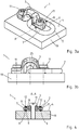
- Figure 1 shows an attachment point or lashing point 1 according to the invention.
- This has an eyelet body 2 and a base body 3.
- the base body 3 is designed here as a weld-on tab and can be coupled to the base 4 via a material connection (not shown in more detail).
- the base body 3 itself has an opening in which the eyelet body 2 is arranged. The opening can also result between the base body 3 and a base 4 on which the base body 3 is fastened.
- the eyelet body 2 is pivotable, as in Figure 1 and 2 each shown in the rest position. It is, however, mounted on the base body 3 in the pivoting direction 5 so that it can be pivoted through 180 °. In the rest position, a front side 6 of the eyelet body 2 shown here lies on the base 4.
- a magnet 9 is arranged in both legs 7 of the eyelet body 2 on the front 6 and the rear 8.
- the magnets 9 are arranged sunk in relation to the front 6 or rear 8, in such a way that the front 6 or rear 8 is flat or planar.
- the magnet 9 does not protrude from the contour of the front side 6 and cannot lead to the lashing strap getting caught here.
- the magnet 9 is in each case recessed in a receptacle 10 and, as shown here, glued into the receptacle 10.
- Figure 3a and 3b and FIG. 4 show a further embodiment variant of an attachment point or lashing point 1 according to the invention.
- Figure 3a shows a perspective view and Figure 3b a side view.
- Figure 4 shows a sectional view along the section line AA.
- the attachment point or lashing point 1 is fastened to a base 4 of an object 19.
- a base body 3 in the form of a bracket is screwed to the base 4 via two screw bolts 11.
- the eyelet body 2 is in turn pivotally mounted on the base body 3.
- magnets 9 are arranged on the front 6 and rear 8 of each leg 7.
- the eyelet body 2 is made of a round steel.
- the outer side 12 of the magnet 9 can preferably be adapted to the outer contour of the front side 6 or rear side 8 in a continuous manner. In this case, the outside 12 of the respective magnet 9 would be rounded. Here too there is an essentially smooth or seamless Surface without the magnet 9 protruding from the surface or being countersunk relative to the surface. If the eyelet body 2 is raised from the base 4, the magnetic force exerted is overcome and the eyelet body 2 can be pivoted into the use position. In the rest position, a distance or play 25 can be formed in particular between the base body 3 and the eyelet body 2. Because the eyelet body 2 is held on the base 4 by the magnets 9, there are no rattling noises and also no uncontrolled movement or movement of the eyelet body 2 not required in the base body 3.
- Figure 5 to 7 show a third embodiment variant of the attachment point or lashing point 1 according to the invention.
- an eyelet body 2 is provided, which is coupled to the ground via a two-part base body 3, which is arranged laterally.
- the base body 3 are preferably welded to the base 4 via a thermal joining seam, not shown.
- the eyelet body 2 has laterally projecting legs 7, a respective leg 13 engaging in the base body 3.
- a magnet 9 is arranged on a front side 6 and on a rear side 8, in such a way that, in a rest position, the magnets 9 on one side, ie front side 6 and rear side 8, rest on the base 4 and the eyelet body 2 hold in the rest position due to the magnetic force.
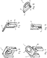
- Figures 8 to 12 show a further embodiment variant of a lifting point or lashing point 1.
- a lashing point is from the DE 20 2015 100 750 U1 known.
- magnets 9 are inserted on an underside of the laterally projecting legs.
- FIGs 8 and 11 shown rest position of the respective magnet 9 on an underside 16 of the link 17 and here hold the eyelet body 2 in the sunken rest position in addition to its weight by magnetic force.
- the magnet 9 according to Figures 9 and 10 rest in the use position on an inside 18 of the link 17 and are therefore held in the use position by the magnet 9 due to the magnetic force in addition to the support due to the weight.
- Figure 13 to 16 show a further variant of a stop or lashing point 1 in different views.
- an eyelet body 2 is formed with laterally projecting legs 13.
- the eyelet body 2 is mounted in a base body 3 in the form of a cassette, in particular a welded-in cassette. For this purpose, it can be brought into a rest position (not shown) via a backdrop 17 or as in FIG Figures 13, 14 and 15 shown to be held in a position of use. In the use position, the eyelet body 2 projects beyond the base body 3 and is also pivotably mounted in the base body 3.
- a rear side 8 of the eyelet body 2 is supported on a rear wall 20 of the base body 3.
- part 21 of rear wall 20 projects over an upper side 22.
- the part 21 is arranged at an angle ⁇ at an angle to the wall 20, so that the eyelet body 2 is also supported at an angle in the use position.
- the rear side 8 of the eyelet body 2 is supported on an end face 23 of the wall 20.
- magnets 9 are inserted into the eyelet body 2, so that the magnets 9 hold the eyelet body 2 supported in the use position with a magnetic force.
- the eyelet body 2 can also be supported in the use position due to its weight.
- magnets 9 can also be used, which in particular in a Figure 11 shown rest position keep the eyelet body 2 sunk in the cassette.
- the base body 3 in the form of the cassette according to Figure 15 is formed by the rear wall 20 and two side welding plates 24, in which the scenes 17 are arranged.
Landscapes
- Engineering & Computer Science (AREA)
- General Engineering & Computer Science (AREA)
- Mechanical Engineering (AREA)
- Transportation (AREA)
- Fittings On The Vehicle Exterior For Carrying Loads, And Devices For Holding Or Mounting Articles (AREA)
- Hooks, Suction Cups, And Attachment By Adhesive Means (AREA)
Description
Die vorliegende Erfindung betrifft einen Anschlagpunkt oder Zurrpunkt gemäß den Merkmalen im Oberbegriff von Patentanspruch 1.The present invention relates to an attachment point or lashing point according to the features in the preamble of
Aus dem Stand der Technik ist es bekannt, Anschlagpunkte oder Zurrpunkte an zu hebenden Gegenständen oder auf einem Untergrund bzw. einer Ladefläche anzubringen. Beispielsweise werden derartige Anschlagpunkte oder Zurrpunkte an Containern festgelegt. Auch können Anschlagpunkte oder Zurrpunkte auf oder seitlich an der Ladefläche eines Transportfahrzeuges gekoppelt werden.It is known from the prior art to attach lifting points or lashing points to objects to be lifted or on a surface or a loading surface. For example, such attachment points or lashing points are set on containers. Anchor points or lashing points can also be coupled on or to the side of the loading area of a transport vehicle.
Damit der Anschlagpunkt oder Zurrpunkt für logistische Arbeiten, beispielsweise beim Verladen oder Transportieren, Be- oder Entladen von Gegenständen oder an abgestellten Containern nicht störend übersteht, sind aus dem Stand der Technik bekannte Anschlagpunkte oder Zurrpunkte zumeist in einer Ruheposition angeordnet. Aus der Ruheposition können sie in eine Gebrauchsposition verbracht werden.So that the attachment point or lashing point for logistical work, for example when loading or transporting, loading or unloading objects or on parked containers, does not get in the way, attachment points or lashing points known from the prior art are usually in a rest position arranged. They can be moved from the rest position into a use position.
Ein Ösenkörper eines Anschlagpunktes oder Zurrpunktes hat ein Eigengewicht von mehreren Hundert Gramm oder gar Kilogramm. Zumeist ist der Ösenkörper aus einem Stahlwerkstoff, zumindest jedoch aus einem Leichtmetallwerkstoff hergestellt. Liegt dieser in der Ruheposition auf einem Gegenstand oder Untergrund auf, bzw. ist in einer Ruheposition versenkt gelagert, so kommt es bei Nichtgebrauch unter Umständen zu einer störenden Geräuschbildung. Auch kann die Ruheposition in unkontrollierter und ungewollter Weise verlassen werden.An eyelet body of an attachment point or lashing point has a weight of several hundred grams or even kilograms. The eyelet body is usually made of a steel material, but at least of a light metal material. If it lies on an object or surface in the rest position, or is sunk in a rest position, it can lead to disturbing noise when not in use. The rest position can also be left in an uncontrolled and unwanted manner.
Aus der
Aus der
Aufgabe der vorliegenden Erfindung ist es daher, einen Anschlagpunkt oder Zurrpunkt derart weiterzubilden, dass dieser einfach und effektiv eine Ruheposition einnehmen kann und in dieser lagefixiert gehalten ist.It is therefore an object of the present invention to further develop an attachment point or lashing point in such a way that it can simply and effectively assume a rest position and is held in a fixed position there.
Die zuvor genannte Aufgabe wird erfindungsgemäß mit den Merkmalen von Patentanspruch 1 gelöst.The aforementioned object is achieved according to the invention with the features of
Vorteilhafte Ausgestaltungsvarianten der vorliegenden Erfindung sind Gegenstand der abhängigen Ansprüche.Advantageous design variants of the present invention are the subject of the dependent claims.
Der Anschlagpunkt oder Zurrpunkt wird an einem Gegenstand bzw. auf einem Untergrund befestigt. Bei Gebrauch wird der Anschlagpunkt oder Zurrpunkt mit einem Hebe-, Zug- oder Zurrmittel gekoppelt. Beispielsweise wird ein Haken eingehängt oder ein Zurrband oder eine Befestigungskette hindurchgezogen. Hierzu weist der Anschlagpunkt oder Zurrpunkt einen Ösenkörper auf. Insbesondere ist der Ösenkörper als umlaufend geschlossene Öse ausgebildet. Die Öse kann dabei U-förmig bzw. oval ausgebildet sein. Die Öse kann jedoch auch ringförmig oder kreisförmig ausgebildet sein.The attachment point or lashing point is attached to an object or on a surface. When in use, the attachment point or lashing point is coupled with a lifting, pulling or lashing device. For example, a hook is hooked in or a lashing strap or a fastening chain is pulled through. For this purpose, the attachment point or lashing point has an eyelet body. In particular, the eyelet body is designed as a circumferentially closed eyelet. The eyelet can be U-shaped or be oval. However, the eyelet can also be ring-shaped or circular.
Der Ösenkörper ist unter Eingliederung eines Basiskörpers an dem Gegenstand gekoppelt. Der Basiskörper ist hierzu insbesondere fest mit dem Gegenstand gekoppelt. Bei dem Basiskörper kann es sich zum Beispiel um Einschweißhülsen oder auch um eine Einschweißkassette handeln. Der Basiskörper kann auch als Bügelkörper ausgebildet sein. Insbesondere kann der Basiskörper auch formschlüssig, beispielsweise durch eine Verschraubung mit dem Gegenstand gekoppelt sein. Gegenüber dem Basiskörper relativ beweglich ist dann der Ösenkörper gelagert. Der Ösenkörper ist insbesondere schwenkbar gegenüber dem Basiskörper und somit auch gegenüber dem Gegenstand bzw. dem Untergrund gelagert. Der Ösenkörper kann mindestens eine Ruheposition einnehmen. Diese ist bevorzugt entweder auf dem Untergrund des Gegenstandes liegend oder aber in bzw. mit dem Basiskörper gegenüber dem Untergrund des Gegenstandes versenkt gelagert. Von der Ruheposition kann nunmehr der Ösenkörper in eine Gebrauchsposition gebracht werden.The eyelet body is coupled to the object by incorporating a base body. For this purpose, the base body is in particular firmly coupled to the object. The base body can be, for example, weld-in sleeves or also a weld-in cassette. The base body can also be designed as a bow body. In particular, the base body can also be coupled to the object in a form-fitting manner, for example by a screw connection. The eyelet body is then mounted so as to be relatively movable with respect to the base body. The eyelet body is, in particular, pivotable with respect to the base body and thus also with respect to the object or the base. The eyelet body can take at least one rest position. This is preferably either lying on the underground of the object or is sunk in or with the base body relative to the underground of the object. The eyelet body can now be brought into a use position from the rest position.
Erfindungsgemäß zeichnet sich der Anschlagpunkt oder Zurrpunkt dadurch aus, dass in dem Ösenkörper mindestens ein Magnet eingebracht ist, dergestalt, dass der Magnet den Ösenkörper mit seiner Magnetkraft in der Ruheposition oder Gebrauchsposition an dem Gegenstand oder auf einem Untergrund und/oder an dem Basiskörper hält.According to the invention, the attachment point or lashing point is characterized in that at least one magnet is introduced into the eyelet body, in such a way that the magnet holds the eyelet body with its magnetic force in the rest position or use position on the object or on a base and / or on the base body.
Der Magnet ist in dem Ösenkörper selbst eingebracht, bevorzugt gegenüber dem Ösenkörper versenkt gelagert. Liegt der Ösenkörper beispielsweise auf dem Untergrund des Gegenstandes auf, so übt der Magnet eine Magnetkraft auf den Untergrund aus und hält den Ösenkörper fest an dem Untergrund. Ein Klappern wird hierdurch vermieden. Gleichzeitig wird vermieden, dass der Ösenkörper aus dieser Ruheposition unbeabsichtigt herausbewegt wird. Erst bei Überschreiten eines Kraftniveaus, beispielsweise Aufnahme des Ösenkörpers durch die Hand eines anwendenden Monteurs, wird die Magnetkraft überwunden und der Ösenkörper aus der Ruheposition in Gebrauchsposition gebracht.The magnet is introduced into the eyelet body itself, preferably sunk in relation to the eyelet body. If the eyelet body lies, for example, on the base of the object, the magnet exerts a magnetic force on the base and holds the eyelet body firmly on the base. This prevents rattling. At the same time it is avoided that the eyelet body is inadvertently moved out of this rest position. The magnetic force is only overcome and the eyelet body is brought out of the rest position into the use position only when a force level is exceeded, for example by the hand of an assembler taking up the eyelet body.
Vorzugsweise ist der Gegenstand bzw. Untergrund aus Stahlwerkstoff ausgebildet. Sollte der Gegenstand bzw. Untergrund nicht magnetisch sein, so ist weiterhin im Rahmen der Erfindung vorgesehen, hier entsprechende Magneten und/oder Metallkörper einzubringen, so dass der Ösenkörper in Ruheposition gehalten ist.The object or base is preferably formed from steel material. If the object or base is not magnetic, it is further provided within the scope of the invention to introduce corresponding magnets and / or metal bodies here, so that the eyelet body is held in the rest position.
Um den Magneten nunmehr in den Ösenkörper einzubringen, ist insbesondere vorgesehen, dass Rohmagneten verwendet werden. Diese sind als Zylinder oder Rechteckkörper bereitgestellt. Die Magneten werden dann in den Ösenkörper eingebracht. Hierzu kann im Falle eines Zylinders insbesondere eine Bohrung, beispielsweise eine Sacklochbohrung oder eine Ausfräsung, vorgenommen werden. Der Magnet selbst wird dann bevorzugt in der Ausnehmung verklebt. Hierzu wird besonders bevorzugt ein Zwei-Komponenten-Kleber verwendet.In order to introduce the magnet into the eyelet body, it is particularly provided that raw magnets are used. These are provided as cylinders or rectangular bodies. The magnets are then inserted into the eyelet body. For this purpose, in the case of a cylinder, in particular a bore, for example a blind hole or a milling, can be carried out. The magnet itself is then preferably glued in the recess. For this purpose, a two-component adhesive is particularly preferably used.
Es ist im Rahmen der Erfindung jedoch auch vorstellbar, dass der Magnet alternativ oder ergänzend reibschlüssig und/oder formschlüssig gehalten ist. Hierzu kann insbesondere der Magnet in die Ausnehmung in dem Ösenkörper eingepresst werden.However, it is also conceivable within the scope of the invention that the magnet is held alternatively or additionally frictionally and / or positively. For this purpose, the magnet in particular can be pressed into the recess in the eyelet body.
Weiterhin besonders bevorzugt ist im Rahmen der Erfindung vorgesehen, dass der Ösenkörper zwei seitliche gegenüberliegende Schenkel aufweist. Bevorzugt ist in mindestens einem Schenkel auf einer Seite ein Magnet angeordnet. In einer besonders bevorzugten Ausgestaltungsvariante ist in mindestens einem Schenkel und auf jeder Seite ein Magnet angeordnet. Beispielsweise kann ein Ösenkörper somit zwei gegenüberliegende Ruhepositionen einnehmen. Zum einen kann der Ösenkörper auf seine Rückseite gelegt werden. Der Ösenkörper kann auch um ca. 180° geschwenkt werden und auf seine Vorderseite gelegt werden. Besonders bevorzugt ist vorgesehen, dass in jedem Schenkel auf jeder Seite ein Magnet vorgesehen ist. Somit sind mindestens zwei Magnete auf der Vorderseite und mindestens zwei Magnete auf der Rückseite vorgesehen, welche dann in der jeweiligen Ruheposition mittels Magnetkraft den Ösenkörper in der Ruheposition halten.Furthermore, it is particularly preferably provided in the context of the invention that the eyelet body has two lateral, opposite legs. A magnet is preferably arranged in at least one leg on one side. In a particularly preferred embodiment variant, a magnet is arranged in at least one leg and on each side. For example, an eyelet body can thus assume two opposite rest positions. On the one hand, the eyelet body can be placed on its back. The eyelet body can also be swiveled by approx. 180 ° and placed on its front. It is particularly preferably provided that a magnet is provided in each leg on each side. Thus, at least two magnets are provided on the front and at least two magnets on the back, which then hold the eyelet body in the rest position by means of magnetic force in the respective rest position.
Besonders bevorzugt ist ein jeweiliger Magnet derart versenkt in dem Ösenkörper angeordnet, dass er mit einer den Magneten umgebenden Randfläche im Wesentlichen plan bzw. eben abschließt. Bei der Handhabung des Ösenkörpers steht somit der Magnet nicht störend gegenüber der jeweiligen Oberfläche über. Zumindest jedoch ist der Magnet versenkt angeordnet, so dass er nicht gegenüber einer Vorderseite bzw. Rückseite des Ösenkörpers übersteht.A respective magnet is particularly preferably recessed in the eyelet body in such a way that it terminates essentially flat or even with an edge surface surrounding the magnet. When handling the eyelet body, the magnet does not protrude from the surface in question. At least, however, the magnet is arranged sunk so that it does not protrude from a front or back of the eyelet body.
Alternativ kann auch vorgesehen sein, dass der Ösenkörper seitlich abstehende Schenkel aufweist. Ein Magnet kann hierbei dann weiterhin bevorzugt in einem Schenkel angeordnet sein. Bevorzugt ist in einer solchen Ausgestaltungsvariante der Ösenkörper in einem Basiskörper versenkt gelagert. Der Basiskörper ist besonders bevorzugt eine Kassette. Wird der Ösenkörper in dem Basiskörper versenkt, so liegen in Ruheposition die Schenkel an einer Unterseite der Kassette, insbesondere an einer Unterseite einer Führung in der Kassette auf und werden hier von einem Magneten gehalten.Alternatively, it can also be provided that the eyelet body has laterally projecting legs. A magnet can then preferably also be arranged in one leg. In such an embodiment variant, the eyelet body is preferably mounted recessed in a base body. The base body is particularly preferably a cassette. If the eyelet body is sunk into the base body, then in the rest position the legs rest on an underside of the cassette, in particular on an underside of a guide in the cassette, and are held here by a magnet.
Letzterenfalls kann der Magnet derart positioniert sein, dass bei Verbringen des Ösenkörpers in eine Gebrauchsposition der Magnet ebenfalls in einer Führung an der Kassette anliegt und die eingenommene Gebrauchsposition zusätzlich lagefixiert.In the latter case, the magnet can be positioned in such a way that when the eyelet body is brought into a position of use, the magnet also lies in a guide on the cassette and the position of use assumed is additionally fixed in position.
Weitere Vorteile, Merkmale, Eigenschaften und Aspekte der vorliegenden Erfindung sind Gegenstand der nachfolgenden Beschreibung. Bevorzugte Ausgestaltungsvarianten werden in schematischen Figuren dargestellt. Diese dienen dem einfacheren Verständnis der Erfindung. Es zeigen:
Figur 1 und 2- eine erste Ausgestaltungsvariante eines erfindungsgemäßen Anschlagpunktes oder Zurrpunktes auf einem Untergrund,
- Figur 3a,
3b und 4 - eine zweite Ausgestaltungsvariante,
Figur 5, 6 und 7- eine dritte Ausgestaltungsvariante,
Figur 8bis 12- eine vierte alternative Ausgestaltungsvariante eines versenkbaren Anschlagpunktes oder Zurrpunktes und
Figur 13bis 16- eine fünfte alternative Ausgestaltungsvariante eines versenkbaren Anschlagpunktes oder Zurrpunktes.
- Figure 1 and 2
- a first embodiment of an attachment point or lashing point according to the invention on a surface,
- Figures 3a, 3b and 4
- a second design variant,
- Figures 5, 6 and 7
- a third design variant,
- Figure 8 to 12
- a fourth alternative embodiment of a retractable attachment point or lashing point and
- Figure 13 to 16
- a fifth alternative embodiment of a retractable attachment point or lashing point.
In den Figuren werden für gleiche oder ähnliche Bauteile dieselben Bezugszeichen verwendet, auch wenn eine wiederholte Beschreibung aus Vereinfachungsgründen entfällt.The same reference numerals are used in the figures for identical or similar components, even if a repeated description is omitted for reasons of simplification.
In
Erfindungsgemäß ist nunmehr vorgesehen, dass an einer Unterseite der seitlich abstehenden Schenkel 13 Magnete 9 eingesetzt sind. Somit kann in der in
Eine Rückseite 8 des Ösenkörpers 2 stützt sich dabei an einer hinteren Wand 20 des Basiskörpers 3 ab. Hierzu steht ein Teil 21 der hinteren Wand 20 über eine Oberseite 22 über. Insbesondere ist der Teil 21 in einem Winkel β schräg zur Wand 20 angeordnet, so dass der Ösenkörper 2 in Gebrauchsposition ebenfalls schräg abgestützt ist. An einer Stirnseite 23 der Wand 20 stützt sich die Rückseite 8 des Ösenkörpers 2 ab. Hier sind wiederum Magnete 9 in den Ösenkörper 2 eingesetzt, so dass die Magnete 9 den in Gebrauchsposition abgestützten Ösenkörper 2 mit einer Magnetkraft halten. Zusätzlich kann der Ösenkörper 2 aufgrund seiner Gewichtskraft ebenfalls in der Gebrauchsposition abgestützt sein.A
Optional ergänzend oder alternativ können in den seitlich abstehenden Schenkeln 13 analog zu der vorgenannten Ausgestaltungsvariante gemäß der
Der Basiskörper 3 in Form der Kassette gemäß
- 1 -1 -
- AnschlagpunktAnchor point
- 2 -2 -
- ÖsenkörperEyelet body
- 3 -3 -
- BasiskörperBase body
- 4 -4 -
- UntergrundUnderground
- 5 -5 -
- SchwenkrichtungSwivel direction
- 6 -6 -
- Vorderseite zu 2Front to 2
- 7 -7 -
- Schenkelleg
- 8 -8th -
- Rückseite zu 2Back to 2
- 9 -9 -
- Magnetmagnet
- 10 -10 -
- Aufnahmeadmission
- 11 -11 -
- SchraubbolzenBolts
- 12 -12 -
- Außenseite zu 9Outside to 9
- 13 -13 -
- Schenkelleg
- 14 -14 -
- Vertiefungdeepening
- 15 -15 -
- LadeflächeLoading area
- 16 -16 -
- Unterseitebottom
- 17 -17 -
- KulisseBackdrop
- 18 -18 -
- Innenseiteinside
- 19 -19 -
- Gegenstandobject
- 20 -20 -
- Wandwall
- 21 -21 -
- Teil zu 20Part of 20
- 22 -22 -
- Oberseite zu 3Top to 3
- 23 -23 -
- Stirnseite zu 20Face to 20
- 24 -24 -
- EinschweißblechWelding plate
- 25 -25 -
- Spielgame
- β -β -
- Winkelangle
Claims (12)
- Anchorage point or lashing point (1) on an object, wherein the anchorage point or lashing point (1) can be coupled to a lifting, pulling or lashing means, and wherein the anchorage point or lashing point (1) has a base body (3) and an eyelet body (2), wherein the eyelet body (2) is coupled relatively movably over the base body (3) on the object (19) and the eyelet body (2) can be moved from a position of rest into a position of use, characterised in that at least one magnet (9) is inserted into the eyelet body (2) such that the magnet (9) holds the eyelet body (2) with its magnetic force in the position of rest or position of use on the object or on a support surface (4) and/or on the base body (3).
- Anchorage point or lashing point (1) according to claim 1, characterised in that the magnet (9) is a raw magnet, in particular the magnet (9) is designed as a cylinder or rectangular body.
- Anchorage point or lashing point (1) according to claim 1 or 2, characterised in that at least two magnets (9) are introduced into the eyelet body (2), preferably four magnets (9).
- Anchorage point or lashing point (9) according to any of claims 1 to 3, characterised in that the eyelet body (2) has two sides (7), wherein a magnet (9) is arranged respectively in each side (7).
- Anchorage point or lashing point (1) according to claim 4, characterised in that at least one magnet (9) is arranged in each side (7) of the eyelet body (2) on a front side (6) and a rear side (8).
- Anchorage point or lashing point (1) according to any of claims 1 to 5, characterised in that in the eyelet body (2) a recess is formed, in particular a blind bore, in which the magnet (9) is arranged in a recessed position.
- Anchorage point or lashing point (1) according to claim 6, characterised in that the magnet (9) is arranged in a recessed position such that it ends planar or flat with an edge surface surrounding the magnet (9) and/or the magnet (9) has an outer side (12), which is adjusted to the contour of the eyelet body (2), preferably the outer side (12) of the magnet (9) is designed to be rounded.
- Anchorage point or lashing point (1) according to any of claims 1 to 7, characterised in that the magnet (9) is adhered into the eyelet body (2), in particular by means of a two component adhesive.
- Anchorage point or lashing point (1) according to any of claims 1 to 8, characterised in that the magnet (9) is held in the eyelet body (2) in a force-fitting and/or form-fitting manner, preferably the magnet (9) is pressed into the eyelet body (2).
- Anchorage point or lashing point (1) according to any of claims 1 to 9, characterised in that the eyelet body (2) is recessed into the base body (3).
- Anchorage point or lashing point (1) according to any of claims 1 to 3 and 6 to 10, characterised in that the eyelet body (2) has laterally protruding sides (13), wherein a magnet (9) is arranged preferably in at least one side (7).
- Anchorage point or lashing point (1) according to any of claims 1 to 11, characterised in that the anchorage or lashing point (1) is recessed in the position of rest relative to its surrounding support surface (4).
Priority Applications (1)
| Application Number | Priority Date | Filing Date | Title |
|---|---|---|---|
| PL18159479T PL3369949T3 (en) | 2017-03-03 | 2018-03-01 | Anchorage points or lashing point with magnet |
Applications Claiming Priority (1)
| Application Number | Priority Date | Filing Date | Title |
|---|---|---|---|
| DE202017101234.4U DE202017101234U1 (en) | 2017-03-03 | 2017-03-03 | Lifting point or lashing point with magnet |
Publications (2)
| Publication Number | Publication Date |
|---|---|
| EP3369949A1 EP3369949A1 (en) | 2018-09-05 |
| EP3369949B1 true EP3369949B1 (en) | 2020-04-22 |
Family
ID=61563160
Family Applications (1)
| Application Number | Title | Priority Date | Filing Date |
|---|---|---|---|
| EP18159479.7A Active EP3369949B1 (en) | 2017-03-03 | 2018-03-01 | Anchorage points or lashing point with magnet |
Country Status (3)
| Country | Link |
|---|---|
| EP (1) | EP3369949B1 (en) |
| DE (1) | DE202017101234U1 (en) |
| PL (1) | PL3369949T3 (en) |
Cited By (1)
| Publication number | Priority date | Publication date | Assignee | Title |
|---|---|---|---|---|
| EP3912859A1 (en) * | 2020-05-18 | 2021-11-24 | Thiele GmbH & Co. KG | Lashing cartridge module |
Families Citing this family (1)
| Publication number | Priority date | Publication date | Assignee | Title |
|---|---|---|---|---|
| DE202019101641U1 (en) * | 2019-03-21 | 2020-06-23 | Thiele Gmbh & Co. Kg | Lashing point with assembly position |
Family Cites Families (9)
| Publication number | Priority date | Publication date | Assignee | Title |
|---|---|---|---|---|
| DE29500242U1 (en) * | 1995-01-09 | 1996-05-09 | Plogmann, Kurt, 49082 Osnabrück | Lashing bracket on a truck |
| JP2001221375A (en) * | 1995-10-03 | 2001-08-17 | Hitachi Metals Ltd | Magnetic hanging device |
| DE10311805B4 (en) * | 2003-03-12 | 2008-06-26 | Bos Gmbh & Co. Kg | Locking device for receiving module |
| DE20313685U1 (en) * | 2003-09-01 | 2003-10-30 | Barthau Anhängerbau GmbH, 74547 Untermünkheim | Vehicle with loading floor |
| US20130322981A1 (en) * | 2011-07-02 | 2013-12-05 | Sta-Put-Hook, Llc | Tie Down Strap Hook |
| DE202013005581U1 (en) * | 2013-06-21 | 2014-09-22 | Illinois Tool Works Inc. | Device for fastening objects in a luggage or load compartment of a motor vehicle |
| US9345312B1 (en) * | 2015-02-06 | 2016-05-24 | Gregory Washio | Mobile device transportation apparatus |
| DE202015100750U1 (en) | 2015-02-17 | 2015-03-03 | Thiele Gmbh & Co. Kg | lashing point |
| DE202015100857U1 (en) | 2015-02-23 | 2015-03-04 | Thiele Gmbh & Co. Kg | Anchor point with fixing washer |
-
2017
- 2017-03-03 DE DE202017101234.4U patent/DE202017101234U1/en not_active Expired - Lifetime
-
2018
- 2018-03-01 EP EP18159479.7A patent/EP3369949B1/en active Active
- 2018-03-01 PL PL18159479T patent/PL3369949T3/en unknown
Non-Patent Citations (1)
| Title |
|---|
| None * |
Cited By (1)
| Publication number | Priority date | Publication date | Assignee | Title |
|---|---|---|---|---|
| EP3912859A1 (en) * | 2020-05-18 | 2021-11-24 | Thiele GmbH & Co. KG | Lashing cartridge module |
Also Published As
| Publication number | Publication date |
|---|---|
| DE202017101234U1 (en) | 2018-06-05 |
| EP3369949A1 (en) | 2018-09-05 |
| PL3369949T3 (en) | 2020-11-30 |
Similar Documents
| Publication | Publication Date | Title |
|---|---|---|
| EP3115254B1 (en) | Tie-down device | |
| EP3369949B1 (en) | Anchorage points or lashing point with magnet | |
| DE202017103599U1 (en) | Rung bag assemblies for pickup trucks | |
| EP2698296A2 (en) | Length-adjustable telescopic tube | |
| EP2781406B1 (en) | Fixing for lashing straps on a loading area | |
| EP3000655B1 (en) | Device for fixing load objects | |
| DE102020102042A1 (en) | TRUCK TAILGATE WITH RING TAPE | |
| DE202016004557U1 (en) | Cargo securing cover device for agricultural transport vehicles | |
| DE2048373A1 (en) | Movable vehicle roof | |
| DE202015100857U1 (en) | Anchor point with fixing washer | |
| DE102005042288A1 (en) | Loading edge covering for use in motor vehicle rear area, has opening, and flap device that is movable from closing position into opening position and detachably fastened to lining part, where lining part is made from stainless steel | |
| DE202010011440U1 (en) | Device for securing cargo on a cargo bed of a vehicle body | |
| EP2998158A1 (en) | Perforated sheet path | |
| EP2080729B1 (en) | Loading crane with load carrying means that can be brought in a transport position | |
| EP3015311B1 (en) | Commercial vehicle structure and method for securing the position of an item transported on a transport platform of a commercial vehicle | |
| EP2428397B1 (en) | Perforated profile rail | |
| DE102012108359B4 (en) | Commercial vehicle | |
| DE202017004635U1 (en) | With retractable lashing ring combinable stanchion foot | |
| DE102017104484B4 (en) | Lashing point with welding cassette | |
| DE202017104826U1 (en) | Lashing point with magnetic lock | |
| DE10322569B4 (en) | Lashing bracket for attachment to a carrier | |
| DE202013000332U1 (en) | Motor vehicle with loading space, loadable in two loading positions | |
| DE102010023885A1 (en) | Device for fixing cargo securing elements | |
| EP3546260A1 (en) | Tarpaulin closure element, tarpaulin and vehicle body | |
| DE202009009270U1 (en) | Vehicle and lashing element |
Legal Events
| Date | Code | Title | Description |
|---|---|---|---|
| PUAI | Public reference made under article 153(3) epc to a published international application that has entered the european phase |
Free format text: ORIGINAL CODE: 0009012 |
|
| STAA | Information on the status of an ep patent application or granted ep patent |
Free format text: STATUS: THE APPLICATION HAS BEEN PUBLISHED |
|
| STAA | Information on the status of an ep patent application or granted ep patent |
Free format text: STATUS: REQUEST FOR EXAMINATION WAS MADE |
|
| AK | Designated contracting states |
Kind code of ref document: A1 Designated state(s): AL AT BE BG CH CY CZ DE DK EE ES FI FR GB GR HR HU IE IS IT LI LT LU LV MC MK MT NL NO PL PT RO RS SE SI SK SM TR |
|
| AX | Request for extension of the european patent |
Extension state: BA ME |
|
| 17P | Request for examination filed |
Effective date: 20180809 |
|
| GRAP | Despatch of communication of intention to grant a patent |
Free format text: ORIGINAL CODE: EPIDOSNIGR1 |
|
| STAA | Information on the status of an ep patent application or granted ep patent |
Free format text: STATUS: GRANT OF PATENT IS INTENDED |
|
| INTG | Intention to grant announced |
Effective date: 20191205 |
|
| RIN1 | Information on inventor provided before grant (corrected) |
Inventor name: NORPOTH, BERNHARD |
|
| GRAS | Grant fee paid |
Free format text: ORIGINAL CODE: EPIDOSNIGR3 |
|
| GRAA | (expected) grant |
Free format text: ORIGINAL CODE: 0009210 |
|
| STAA | Information on the status of an ep patent application or granted ep patent |
Free format text: STATUS: THE PATENT HAS BEEN GRANTED |
|
| AK | Designated contracting states |
Kind code of ref document: B1 Designated state(s): AL AT BE BG CH CY CZ DE DK EE ES FI FR GB GR HR HU IE IS IT LI LT LU LV MC MK MT NL NO PL PT RO RS SE SI SK SM TR |
|
| REG | Reference to a national code |
Ref country code: CH Ref legal event code: EP |
|
| REG | Reference to a national code |
Ref country code: DE Ref legal event code: R096 Ref document number: 502018001234 Country of ref document: DE |
|
| REG | Reference to a national code |
Ref country code: IE Ref legal event code: FG4D Free format text: LANGUAGE OF EP DOCUMENT: GERMAN |
|
| REG | Reference to a national code |
Ref country code: AT Ref legal event code: REF Ref document number: 1260496 Country of ref document: AT Kind code of ref document: T Effective date: 20200515 |
|
| REG | Reference to a national code |
Ref country code: LT Ref legal event code: MG4D |
|
| REG | Reference to a national code |
Ref country code: NL Ref legal event code: MP Effective date: 20200422 |
|
| PG25 | Lapsed in a contracting state [announced via postgrant information from national office to epo] |
Ref country code: LT Free format text: LAPSE BECAUSE OF FAILURE TO SUBMIT A TRANSLATION OF THE DESCRIPTION OR TO PAY THE FEE WITHIN THE PRESCRIBED TIME-LIMIT Effective date: 20200422 Ref country code: PT Free format text: LAPSE BECAUSE OF FAILURE TO SUBMIT A TRANSLATION OF THE DESCRIPTION OR TO PAY THE FEE WITHIN THE PRESCRIBED TIME-LIMIT Effective date: 20200824 Ref country code: GR Free format text: LAPSE BECAUSE OF FAILURE TO SUBMIT A TRANSLATION OF THE DESCRIPTION OR TO PAY THE FEE WITHIN THE PRESCRIBED TIME-LIMIT Effective date: 20200723 Ref country code: NO Free format text: LAPSE BECAUSE OF FAILURE TO SUBMIT A TRANSLATION OF THE DESCRIPTION OR TO PAY THE FEE WITHIN THE PRESCRIBED TIME-LIMIT Effective date: 20200722 Ref country code: NL Free format text: LAPSE BECAUSE OF FAILURE TO SUBMIT A TRANSLATION OF THE DESCRIPTION OR TO PAY THE FEE WITHIN THE PRESCRIBED TIME-LIMIT Effective date: 20200422 Ref country code: IS Free format text: LAPSE BECAUSE OF FAILURE TO SUBMIT A TRANSLATION OF THE DESCRIPTION OR TO PAY THE FEE WITHIN THE PRESCRIBED TIME-LIMIT Effective date: 20200822 Ref country code: SE Free format text: LAPSE BECAUSE OF FAILURE TO SUBMIT A TRANSLATION OF THE DESCRIPTION OR TO PAY THE FEE WITHIN THE PRESCRIBED TIME-LIMIT Effective date: 20200422 Ref country code: FI Free format text: LAPSE BECAUSE OF FAILURE TO SUBMIT A TRANSLATION OF THE DESCRIPTION OR TO PAY THE FEE WITHIN THE PRESCRIBED TIME-LIMIT Effective date: 20200422 |
|
| PG25 | Lapsed in a contracting state [announced via postgrant information from national office to epo] |
Ref country code: RS Free format text: LAPSE BECAUSE OF FAILURE TO SUBMIT A TRANSLATION OF THE DESCRIPTION OR TO PAY THE FEE WITHIN THE PRESCRIBED TIME-LIMIT Effective date: 20200422 Ref country code: HR Free format text: LAPSE BECAUSE OF FAILURE TO SUBMIT A TRANSLATION OF THE DESCRIPTION OR TO PAY THE FEE WITHIN THE PRESCRIBED TIME-LIMIT Effective date: 20200422 Ref country code: LV Free format text: LAPSE BECAUSE OF FAILURE TO SUBMIT A TRANSLATION OF THE DESCRIPTION OR TO PAY THE FEE WITHIN THE PRESCRIBED TIME-LIMIT Effective date: 20200422 Ref country code: BG Free format text: LAPSE BECAUSE OF FAILURE TO SUBMIT A TRANSLATION OF THE DESCRIPTION OR TO PAY THE FEE WITHIN THE PRESCRIBED TIME-LIMIT Effective date: 20200722 |
|
| PG25 | Lapsed in a contracting state [announced via postgrant information from national office to epo] |
Ref country code: AL Free format text: LAPSE BECAUSE OF FAILURE TO SUBMIT A TRANSLATION OF THE DESCRIPTION OR TO PAY THE FEE WITHIN THE PRESCRIBED TIME-LIMIT Effective date: 20200422 |
|
| REG | Reference to a national code |
Ref country code: DE Ref legal event code: R097 Ref document number: 502018001234 Country of ref document: DE |
|
| PG25 | Lapsed in a contracting state [announced via postgrant information from national office to epo] |
Ref country code: CZ Free format text: LAPSE BECAUSE OF FAILURE TO SUBMIT A TRANSLATION OF THE DESCRIPTION OR TO PAY THE FEE WITHIN THE PRESCRIBED TIME-LIMIT Effective date: 20200422 Ref country code: RO Free format text: LAPSE BECAUSE OF FAILURE TO SUBMIT A TRANSLATION OF THE DESCRIPTION OR TO PAY THE FEE WITHIN THE PRESCRIBED TIME-LIMIT Effective date: 20200422 Ref country code: ES Free format text: LAPSE BECAUSE OF FAILURE TO SUBMIT A TRANSLATION OF THE DESCRIPTION OR TO PAY THE FEE WITHIN THE PRESCRIBED TIME-LIMIT Effective date: 20200422 Ref country code: EE Free format text: LAPSE BECAUSE OF FAILURE TO SUBMIT A TRANSLATION OF THE DESCRIPTION OR TO PAY THE FEE WITHIN THE PRESCRIBED TIME-LIMIT Effective date: 20200422 Ref country code: SM Free format text: LAPSE BECAUSE OF FAILURE TO SUBMIT A TRANSLATION OF THE DESCRIPTION OR TO PAY THE FEE WITHIN THE PRESCRIBED TIME-LIMIT Effective date: 20200422 Ref country code: DK Free format text: LAPSE BECAUSE OF FAILURE TO SUBMIT A TRANSLATION OF THE DESCRIPTION OR TO PAY THE FEE WITHIN THE PRESCRIBED TIME-LIMIT Effective date: 20200422 Ref country code: IT Free format text: LAPSE BECAUSE OF FAILURE TO SUBMIT A TRANSLATION OF THE DESCRIPTION OR TO PAY THE FEE WITHIN THE PRESCRIBED TIME-LIMIT Effective date: 20200422 |
|
| PG25 | Lapsed in a contracting state [announced via postgrant information from national office to epo] |
Ref country code: SK Free format text: LAPSE BECAUSE OF FAILURE TO SUBMIT A TRANSLATION OF THE DESCRIPTION OR TO PAY THE FEE WITHIN THE PRESCRIBED TIME-LIMIT Effective date: 20200422 |
|
| PLBE | No opposition filed within time limit |
Free format text: ORIGINAL CODE: 0009261 |
|
| STAA | Information on the status of an ep patent application or granted ep patent |
Free format text: STATUS: NO OPPOSITION FILED WITHIN TIME LIMIT |
|
| 26N | No opposition filed |
Effective date: 20210125 |
|
| PG25 | Lapsed in a contracting state [announced via postgrant information from national office to epo] |
Ref country code: SI Free format text: LAPSE BECAUSE OF FAILURE TO SUBMIT A TRANSLATION OF THE DESCRIPTION OR TO PAY THE FEE WITHIN THE PRESCRIBED TIME-LIMIT Effective date: 20200422 |
|
| PG25 | Lapsed in a contracting state [announced via postgrant information from national office to epo] |
Ref country code: MC Free format text: LAPSE BECAUSE OF FAILURE TO SUBMIT A TRANSLATION OF THE DESCRIPTION OR TO PAY THE FEE WITHIN THE PRESCRIBED TIME-LIMIT Effective date: 20200422 |
|
| REG | Reference to a national code |
Ref country code: CH Ref legal event code: PL |
|
| PG25 | Lapsed in a contracting state [announced via postgrant information from national office to epo] |
Ref country code: LI Free format text: LAPSE BECAUSE OF NON-PAYMENT OF DUE FEES Effective date: 20210331 Ref country code: CH Free format text: LAPSE BECAUSE OF NON-PAYMENT OF DUE FEES Effective date: 20210331 Ref country code: FR Free format text: LAPSE BECAUSE OF NON-PAYMENT OF DUE FEES Effective date: 20210331 Ref country code: IE Free format text: LAPSE BECAUSE OF NON-PAYMENT OF DUE FEES Effective date: 20210301 |
|
| PGFP | Annual fee paid to national office [announced via postgrant information from national office to epo] |
Ref country code: DE Payment date: 20220330 Year of fee payment: 5 |
|
| PGFP | Annual fee paid to national office [announced via postgrant information from national office to epo] |
Ref country code: PL Payment date: 20220221 Year of fee payment: 5 Ref country code: LU Payment date: 20220323 Year of fee payment: 5 Ref country code: BE Payment date: 20220321 Year of fee payment: 5 |
|
| GBPC | Gb: european patent ceased through non-payment of renewal fee |
Effective date: 20220301 |
|
| PG25 | Lapsed in a contracting state [announced via postgrant information from national office to epo] |
Ref country code: GB Free format text: LAPSE BECAUSE OF NON-PAYMENT OF DUE FEES Effective date: 20220301 |
|
| PG25 | Lapsed in a contracting state [announced via postgrant information from national office to epo] |
Ref country code: CY Free format text: LAPSE BECAUSE OF FAILURE TO SUBMIT A TRANSLATION OF THE DESCRIPTION OR TO PAY THE FEE WITHIN THE PRESCRIBED TIME-LIMIT Effective date: 20200422 |
|
| PG25 | Lapsed in a contracting state [announced via postgrant information from national office to epo] |
Ref country code: HU Free format text: LAPSE BECAUSE OF FAILURE TO SUBMIT A TRANSLATION OF THE DESCRIPTION OR TO PAY THE FEE WITHIN THE PRESCRIBED TIME-LIMIT; INVALID AB INITIO Effective date: 20180301 |
|
| REG | Reference to a national code |
Ref country code: DE Ref legal event code: R119 Ref document number: 502018001234 Country of ref document: DE |
|
| REG | Reference to a national code |
Ref country code: BE Ref legal event code: MM Effective date: 20230331 |
|
| PG25 | Lapsed in a contracting state [announced via postgrant information from national office to epo] |
Ref country code: LU Free format text: LAPSE BECAUSE OF NON-PAYMENT OF DUE FEES Effective date: 20230301 |
|
| PG25 | Lapsed in a contracting state [announced via postgrant information from national office to epo] |
Ref country code: DE Free format text: LAPSE BECAUSE OF NON-PAYMENT OF DUE FEES Effective date: 20231003 |
|
| PG25 | Lapsed in a contracting state [announced via postgrant information from national office to epo] |
Ref country code: BE Free format text: LAPSE BECAUSE OF NON-PAYMENT OF DUE FEES Effective date: 20230331 |
|
| PG25 | Lapsed in a contracting state [announced via postgrant information from national office to epo] |
Ref country code: MK Free format text: LAPSE BECAUSE OF FAILURE TO SUBMIT A TRANSLATION OF THE DESCRIPTION OR TO PAY THE FEE WITHIN THE PRESCRIBED TIME-LIMIT Effective date: 20200422 |
|
| REG | Reference to a national code |
Ref country code: AT Ref legal event code: MM01 Ref document number: 1260496 Country of ref document: AT Kind code of ref document: T Effective date: 20230301 |
|
| PG25 | Lapsed in a contracting state [announced via postgrant information from national office to epo] |
Ref country code: AT Free format text: LAPSE BECAUSE OF NON-PAYMENT OF DUE FEES Effective date: 20230301 |
|
| PG25 | Lapsed in a contracting state [announced via postgrant information from national office to epo] |
Ref country code: AT Free format text: LAPSE BECAUSE OF NON-PAYMENT OF DUE FEES Effective date: 20230301 |
|
| PG25 | Lapsed in a contracting state [announced via postgrant information from national office to epo] |
Ref country code: PL Free format text: LAPSE BECAUSE OF NON-PAYMENT OF DUE FEES Effective date: 20230301 |
|
| PG25 | Lapsed in a contracting state [announced via postgrant information from national office to epo] |
Ref country code: PL Free format text: LAPSE BECAUSE OF NON-PAYMENT OF DUE FEES Effective date: 20230301 |