EP3369348A1 - Verkaufs- und transportbehälter zur warenpräsentation - Google Patents
Verkaufs- und transportbehälter zur warenpräsentation Download PDFInfo
- Publication number
- EP3369348A1 EP3369348A1 EP18159163.7A EP18159163A EP3369348A1 EP 3369348 A1 EP3369348 A1 EP 3369348A1 EP 18159163 A EP18159163 A EP 18159163A EP 3369348 A1 EP3369348 A1 EP 3369348A1
- Authority
- EP
- European Patent Office
- Prior art keywords
- bottom wall
- sales
- transport container
- container according
- adjusting device
- Prior art date
- Legal status (The legal status is an assumption and is not a legal conclusion. Google has not performed a legal analysis and makes no representation as to the accuracy of the status listed.)
- Granted
Links
- 238000006073 displacement reaction Methods 0.000 claims description 11
- 230000006835 compression Effects 0.000 claims description 8
- 238000007906 compression Methods 0.000 claims description 8
- 238000009434 installation Methods 0.000 claims description 7
- 230000008859 change Effects 0.000 claims description 4
- 230000001404 mediated effect Effects 0.000 claims description 3
- 230000000284 resting effect Effects 0.000 claims description 3
- 230000001960 triggered effect Effects 0.000 claims description 2
- 230000001747 exhibiting effect Effects 0.000 claims 1
- 238000010276 construction Methods 0.000 description 8
- 230000000712 assembly Effects 0.000 description 2
- 238000000429 assembly Methods 0.000 description 2
- 239000013256 coordination polymer Substances 0.000 description 2
- 238000010586 diagram Methods 0.000 description 2
- 230000009467 reduction Effects 0.000 description 2
- 230000000694 effects Effects 0.000 description 1
- 230000006872 improvement Effects 0.000 description 1
- 238000003780 insertion Methods 0.000 description 1
- 230000037431 insertion Effects 0.000 description 1
- 230000010354 integration Effects 0.000 description 1
- 230000007246 mechanism Effects 0.000 description 1
- 230000002093 peripheral effect Effects 0.000 description 1
- 239000013589 supplement Substances 0.000 description 1
- 230000004580 weight loss Effects 0.000 description 1
Images


Classifications
-
- A—HUMAN NECESSITIES
- A47—FURNITURE; DOMESTIC ARTICLES OR APPLIANCES; COFFEE MILLS; SPICE MILLS; SUCTION CLEANERS IN GENERAL
- A47F—SPECIAL FURNITURE, FITTINGS, OR ACCESSORIES FOR SHOPS, STOREHOUSES, BARS, RESTAURANTS OR THE LIKE; PAYING COUNTERS
- A47F5/00—Show stands, hangers, or shelves characterised by their constructional features
- A47F5/10—Adjustable or foldable or dismountable display stands
- A47F5/13—Adjustable or foldable or dismountable display stands made of tubes or wire
-
- A—HUMAN NECESSITIES
- A47—FURNITURE; DOMESTIC ARTICLES OR APPLIANCES; COFFEE MILLS; SPICE MILLS; SUCTION CLEANERS IN GENERAL
- A47F—SPECIAL FURNITURE, FITTINGS, OR ACCESSORIES FOR SHOPS, STOREHOUSES, BARS, RESTAURANTS OR THE LIKE; PAYING COUNTERS
- A47F3/00—Show cases or show cabinets
- A47F3/14—Display trays or containers
- A47F3/142—Display trays to be placed on the floor, e.g. by means of legs or of integrated cabinets underneath
-
- A—HUMAN NECESSITIES
- A47—FURNITURE; DOMESTIC ARTICLES OR APPLIANCES; COFFEE MILLS; SPICE MILLS; SUCTION CLEANERS IN GENERAL
- A47F—SPECIAL FURNITURE, FITTINGS, OR ACCESSORIES FOR SHOPS, STOREHOUSES, BARS, RESTAURANTS OR THE LIKE; PAYING COUNTERS
- A47F3/00—Show cases or show cabinets
- A47F3/14—Display trays or containers
- A47F3/147—Display trays or containers made of tubes or wire
Definitions
- the invention relates to a sales and transport container for the presentation of goods, which is designed in the form of a lattice table according to the preamble of claim 1.
- Containers in the form of mobile lattice tables intended for use in sales rooms are designed both for the transport and for the presentation of goods. This is already in DE 76 28 135 U1
- a container for receiving goods has been proposed, whose particular formed by partially transparent grid plates side parts define a variable interpretable usable space in which a provided for filing the goods bottom wall part can be introduced.
- this bottom wall is provided with lateral support hooks o.
- Connectors so that in the region of respective assigned grating structures on the side walls a positive fixing is possible.
- a change in height for the bottom wall is possible, so that increases in useful space or reductions for different goods can be carried out.
- a device for presenting merchandise is defined as a table for self-service shops.
- a bottom wall to be taken out of the work space is provided, so that the table can be collapsed thereafter.
- a total executed as a removable unit execution of the sales and transport container is in DE 20 2013 009 631 U1 shown, in which case the bottom wall can also be connected via form-fitting support connector with the side panels and additional transverse webs a subdivision of the effective area above allow the bottom wall.
- a collapsible variant of a lattice table with removable bottom wall is in EP 1 640 281 A1 shown.
- the invention is concerned with the problem of designing a sales and transport container designed as a lattice so that with little technical effort a quick adjustment of the container interior to different size or weight having goods is possible and with damage access conditions for operators and customers a damage-proof Supporting the goods is achieved.
- the system is designed so that the bottom wall connected to the actuator can be operated by hand, by foot and / or by means of at least one actuator. Due to different variants of the actuations, an optimal operation of the functionally expanded transport container is then possible for the place of installation.
- the concept of the displaceable with an actuator bottom wall is directed that for each supported on these goods, at least in the region of an open top of the usable space each variable access and use positions can be specified. This is particularly indicated when different sized goods or items are to handle with great weight.
- the system can also be extended by the fact that at least one of the useful space limiting side walls can be moved to an open position. This then also lateral access conditions for the lattice table can be reached, so that when loading and / or unloading of the usable space as low lifting heights as possible for easier handling of the goods. It is conceivable that at least one of the side walls is formed from at least two partial walls, of which at least one can be displaced into an open position. By corresponding reduction of the subregions different sized side openings can thus be produced, and in this area, the bottom wall can be positioned with the adjusting device in an optimal operating height.
- the bottom wall forming a usable surface parallel to the horizontal ground plane at the installation location is preferably adjustable to different altitudes within the useful space by means of the adjusting device. It is also conceivable that by means of the adjusting device, a displacement of the bottom wall can be carried out to beyond the upper edge of the opening of the lattice table and a lowering movement into the work space is introduced into it.
- the bottom wall is held tiltable in the region of the adjusting device. This ensures that the at least accessible from the top of the open space for the customer goods are presentable on an at least partially inclined floor space and thus a removal-friendly access position is defined.
- the adjusting device is designed so that the at least partially horizontally extending or tilted position of use occupying bottom wall can be stepped or continuously moved.
- the connectable to the actuator bottom wall can be carried out with separate sections so that a multipart floor space is created.
- the at least two partial regions can also be displaced individually by means of the at least one adjusting device.
- the bottom wall also has more than two partial areas can have.
- each subarea of the bottom wall is assigned in each case one adjusting device.
- two upper side useful sub-surface engaging under adjusting devices can be introduced into a side wall structure of the lattice table.
- the at least one assembly of bottom wall and adjusting device is designed as a self-sufficient unit. This can also be used independently of the lattice table. For this purpose, it is conceivable that the self-sufficient unit can be defined in a lying on the floor of the installation site use position and thus the bottom wall defines a "borderless" lattice table.
- the optimal implementation of the lattice table concept according to the invention provides that the assembly having the bottom wall has a usable position fixable in or on the components of the lattice table.
- the peripheral side wall structure of the lattice table is used for receiving the self-sufficient structural components of the adjusting device.
- a connecting construction of the adjusting device in the region of the corner-side support posts is conceivable.
- the adjusting device is preferably designed in the form of a scissor arm lift which engages under the bottom wall.
- This has at least two connected by a central support joint scissor arms of known design.
- these scissor arms by means of known fixed-bearing floating supports a displacement in different spreader positions can be mediated, such that thus a change in respective altitudes of the located at the upper ends of the scissor arms bottom wall is achieved.
- a structurally stable and expedient embodiment of this system provides that a respective Scherenarmheber is provided at two of the parallel side edges of the bottom wall. This ensures that the bottom wall can be moved parallel to the ground by means of pairs of pairs of scissor arms opposite each other.
- This low-cost integrated into the lattice table hub system provides that the respective floating bearing of the scissor arms are on the one hand in the region of a lower frame frame by means of engaging in a latching guide connecting strut in different Sp Dahlen fixed.
- a loose bearing of the scissor arm receiving longitudinal groove is provided in the region of the upper bottom wall, so that here a guided movement when adjusting the bottom wall is possible.
- the structural design of acting as an adjusting scissor arm provides that below the bottom wall, a the upper ends of the pair of scissor arms in both the floating bearing and the spaced-apart fixed bearing captive support frame is provided. This ensures that by means of an actuator located on this support frame respective lifting and / or tilting adjustments of the bottom wall can be performed.
- a second embodiment of the lattice table according to the invention with adjustment in the region of the bottom wall provides that this has an adjusting device which is provided with at least one directly acting on the bottom wall actuator.
- the general concept provides that the actuator can be held in the region of the container wall and / or the support posts.
- this direct-acting actuator in each case a force storage device in the form of a spring o. The like.
- the actuator is provided in the region of at least two of the corner-side support post.
- An advantageous simple embodiment of this spring-force accumulator is directed to the fact that in each case a prestressable compression spring is integrated into the system of the support posts. This in vertical mounting position in several of the support post integrable construction can cooperate at the upper end of the compression spring with a guide pinion, which in turn is to be connected to a rack provided in the support post.
- a counterforce generated by the prestressable compression spring can be stored. This is defined as a variably usable lifting force - in particular depending on the weight load generated by the goods in the bottom wall - defined in a lifting movement.
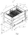
- Fig. 1 is a total of 1 designated sales and transport container for the presentation of goods in supermarkets o. The like. Sales facilities shown.
- the container 1 is provided with respective pairwise opposed vertical longitudinal and transverse side walls 2, 3, 4, 5, which are preferably connected in the region of corner-side support posts 6, 7, 8, 9.
- This constructed in the manner of a lattice container 1 defines a payload space N, in which at least one of the goods not shown in detail removal under cross-bottom wall 10 can be inserted.
- the bottom wall 10 can be moved at least in the unloaded state in different positions of use and fixed in these.
- the concept of the container construction according to the invention provides that now the bottom wall 10 is provided with at least one adjusting device 11 (FIG. Fig. 2 ) can be connected.
- the construction is designed so that the associated with the actuator 11 bottom wall 10 either by hand, by foot and / or by means of at least an actuator 12 ( Fig. 13 ) is displaceable.
- the concept of a displaceable by means of the adjusting device 11 bottom wall 10 is directed to that for goods to be supported at least in the region of an open top 13 of the usable space N variable access and use positions can be specified.
- a directly usable lifting system on the bottom wall 10 is illustrated. This is based on a concept in which the connectable to the bottom wall actuator 11 with a plurality - directly on the bottom wall 10 acting - actuators SG interacts. These actuators SG can both in the region of the container wall (not shown in detail) as well as in the area of at least one support post 7, 8 ( Fig. 3, Fig. 4 ).
- Fig. 2 a schematic diagram is shown, wherein the system has in respective corner regions of the bottom wall 10 of one of the actuators SG, which act as an actuator 11.
- respective compression springs 14 are provided at least in the region of pairwise interacting actuators SG as force accumulators, which are arranged in a vertical prestressing direction according to arrow D (FIG. Fig. 2 ) can be biased so that the actuators SG have a total "internal biasing force" and thus the bottom wall 10 can be acted upon.
- this installation position of the bottom wall 10 is shown in conjunction with the actuators SG having a respective compression spring 14. It is provided that in the region of the actuator SG respectively an upper guide pinion 15 and a pivotally connectable to the bottom wall 10 brake pinion 16 cooperate (arrow A, A '; Fig. 6 ). These two pinions 15 and 16 'can engage in a respective profiling of two parallel racks 17, 17' so that in the installed position according to Fig. 5 a braking effect and thus fixation of the bottom wall 10 by means of a displaceable locking bolt RB is achieved.
- FIGS. 7 and 8 are the engagement conditions in the region of the two pinions 15 and 16 in connection with the two racks 17 and 17 'illustrated in more detail.
- Fig. 2 to Fig. 8 is a direct support of the bottom wall 10 of structural parts of the lattice table 1 shown only schematically.
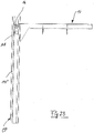
- FIGS. 22 to 25 shown as a second embodiment for direct adjustment of the bottom wall 10.
- This manually executable adjustment of the system is possible here in that in the two parallel C-profiles CP (FIG. Fig. 22 ) each a rack profile 17 "( Fig. 25 ) is provided.
- a tilt according to arrow A ( Fig. 6 ) so that the displacement of the bottom 10 in the direction of arrow B is possible in the retaining pin HB unlocking from the insertion openings SG skew.
- a suitably roll-shaped contact part AG in the C-profile CP is guided so that a user-friendly guided displacement of the bottom 10 is possible and the pinion 16 defined in the rack 17 "can roll.
- a second embodiment of the bottom wall actuator combination provides that preferably one - from the schematic diagrams in FIGS. 9 to 18 more apparent - scissors arm 18 is used as adjusting device 11.
- the bottom wall 10 forming at least region-wise a horizontal wall H, which is parallel to the horizontal H - in a set-up space - by means of the adjusting device 11, can be moved to different altitudes F, F '(FIG. Fig. 16, Fig. 17 ) within the working space N can be fixed.
- FIGS. 12 and 13 A synopsis of FIGS. 12 and 13 shows that the bottom wall 10 is held tiltable in the upper region of the adjusting device 11. This is achieved the goods (not shown) that are openly accessible at least on the upper side 13 of the usable space N can be presented on an area E 'inclined at least in certain areas.
- the bottom wall 10 can be pivoted about a support point SP, for which purpose the application of an actuating device 12 -effective here independently of the actuating device 11 -is conceivable.
- the upper tilt position according to Fig. 13 is a fixation of the bottom wall 10 in the region of the actuator 12 or by means of a mechanical lock (not shown) conceivable.
- the bottom wall 10 occupying the at least partially horizontally extending or tilted positions of use can be combined with variable positioning systems. These are constructed so that in each case a stepped or continuous displacement and positioning of the components is conceivable.
- the bottom wall 10 may also have a multi-part effective area E. Shown here are at least two subregions T and T '( Fig. 9 ), which are individually displaceable by means of at least one respective adjusting device 11. It is also conceivable that the two subregions T, T 'have a common adjusting device (not shown).
- the above-described system of bottom wall 10 and adjusting device 11 in structurally simple and optimal for use design as a self-contained unit BE executable.
- Fig. 1 illustrated compact integration of the modules in the wall-post construction of a lattice table 1 is in the wall structure and an independent modular unit BE - according to Fig. 11 . Fig. 18 . Fig. 19 - applicable.
- the self-sufficient unit BE even without surrounding assemblies ( Fig. 9 . Fig. 20 ) is set in a directly on the floor H of a set-up room resting R use position (not shown).
- known lattice tables can be upgraded by the self-contained unit BE and thus the movable bottom wall 10 can be integrated into existing systems.
- the bottom wall 10 located on the adjusting device 11 can be defined as a functional assembly - instead of a direct bottom support - on the components BR, BR 'of the lattice table 1 known per se in a frame-side connecting position.
- This concept with frame-integrated adjusting device 11 is based on the representations according to Fig. 11 to Fig. 21 described in detail in detail.
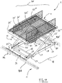
- Fig. 11 the expedient embodiment of the scissor arm lifter becomes clear, wherein the latter has on the parallel side edges 25, 25 'of the bottom wall 10 a respective partial scissor arm lifter 18, such that the bottom wall 10 can be displaced parallel to the ground by means of pairs of opposing scissor arms 20, 20' and 21, 21 ' is (arrow FF; Fig. 19 ).
- FIGS. 14 and 15 are the engagement conditions in the area of the floating bearings 23, 24 (23 ', 24') illustrates, which can be used by a combination of the longitudinal groove 29 'adjustable position of a scissor arm 20 with the engaging in the latch guide 27 other scissor arm 21 thereto , the bottom wall 10 in a the support plane E "forming inclination position KB '( Fig. 14 ) to relocate.
- 27 ' is at least one footrest 33 with retaining hook 33' and return spring 33 "integrated into the frame frame 26.
- a bracket VB is a connection between the two locking guides 27 and 27 'made ( Fig. 18 ).
- Fig. 19 In the execution according to Fig. 19 is - in place of the locking guide 27, Fig. 11 - Provided a lower guide groove 34, 34 'for the lower connecting strut 28 in the region of the floating bearing.
- This system is provided with two cylinders 35, 36 (movement arrow Z) held on the lower frame frame 26. With these provided as an actuator cylinder 35, 36, the continuous adjustment in the region of the scissor arms 20, 20 ', 21, 21' are triggered (arrow FF), so that the bottom wall 10 is moved by a motor in a designated position of use.
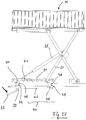
- FIGS. 20 and 21 is a further supplement of the above-described system 1 with the two parallel Scherenarmcruen the lifter 18 shown (similar FIGS. 9 and 10 ).
- 10 additional lifting springs 37 are arranged below the cooperating with the Scherenarmheber-adjusting devices bottom wall.
- the (in accordance with the embodiments shown in FIG Fig. 9 to Fig. 19 Comparable) Scherenarm system largely automatically after applying a bias - for example, by a resting weight according to arrow C '- be moved (arrow D'), so that an effective upon removal of goods Hubunterstützung (arrow FF ') is integrated into the lattice table 1 ,
- An optimal loading and unloading position for the lattice table 1 with displaceable bottom wall 10 can be achieved in that at least one of the useful space N limiting side walls (here: wall 2, Fig. 1 ) in an open position displaced is, so that by lowering the upper part of the wall TW located in a "low position" bottom wall 10 is reached and thus the to be overcome in the loading or removal access height ZH can be kept low (ZH ', ZH ").
- FIGS. 26 to 28 is a second embodiment of the unit BE similar Fig. 18 with the detent adjustment in the area of the footrest 33 (FIG. Fig. 18 ).
- This system has a central gas pressure spring 38, which cooperates with the bottom-side adjusting system.
- the footrest 33 is connected via a transverse tube 39 with the two spring-loaded locking beams 40, 40 '.
- Upon actuation of the footrest 33 is carried out in each case an unlocking in the region of a profile groove 41 by the cross bar 42 of the Scherenarmismes in the position according to Fig. 28 arrives. This is in the direction of arrow RS a shift to the next of the profile grooves 41 out possible.
- This operating mechanism in the region of the latching carrier 40 is in each case provided with a pivot-controlled longitudinal strut 43, the end control legs 44, 45, the guide pin 46, 47 engages in a respective Nutbogen 48, 49.
- the scissors arm 21 having a support roller 50 is in each case held in a hollow profile carrier 51, so that a particularly simple height adjustment of the assembly BE is possible.
Abstract
Description
- Die Erfindung betrifft einen Verkaufs- und Transportbehälter zur Warenpräsentation, der in Form eines Gittertisches gemäß dem Oberbegriff des Anspruchs 1 ausgebildet ist.
- Für eine Anwendung in Verkaufsräumen vorgesehene Behälter in Form von fahrbaren Gittertischen sind sowohl zum Transport als auch zur Präsentation von Waren ausgelegt. Dazu ist bereits in
DE 76 28 135 U1 ein derartiger Behälter zur Aufnahme von Waren vorgeschlagen worden, dessen insbesondere von bereichsweise durchsichtigen Gitterplatten gebildete Seitenteile einen variabel auslegbaren Nutzraum begrenzen, in den ein zur Ablage der Waren vorgesehenes Bodenwandteil einbringbar ist. Dabei ist diese Bodenwandung mit seitlichen Stützhaken o. dgl. Verbindern versehen, so dass im Bereich jeweiliger zugeordneter Gitterstrukturen an den Seitenwänden eine formschlüssige Festlegung möglich ist. Bei einer Nutzung von entsprechend den Gitterlöchern definierten Positionen ist eine Höhenveränderung für die Bodenwandung möglich, so dass damit Nutzraumvergrößerungen bzw. -verkleinerungen für unterschiedliche Waren ausführbar sind. - Aus
DE 28 41 772 A ist ein mit geschlossenen Seitenwandungen versehener Behälter vorgeschlagen, in dem jeweilige die Waren abstützende Palettenteile einbringbar sind. Ausgehend von einer Bodenwandung dieses Behälters ist zwischen den die Waren abstützenden Paletten und der Oberseite der Bodenwandung eine federbelastete Hebeeinrichtung eingebracht. Bei einer durch Entnehmen der Paletten eintretenden Gewichtsabnahme auf der Bodenwandung ist deren selbsttätige Höhenverlagerung nutzbar. - Bei einem Konzept gemäß
EP 1 511 411 B1 wird eine Einrichtung zur Warenpräsentation als Tisch für Selbstbedienungsgeschäfte definiert. Bei diesem System ist eine aus dem Nutzraum zu entnehmende Bodenwandung vorgesehen, so dass der Tisch danach zusammenlegbar ist. - Weiteren Veröffentlichungen gemäß
DE 20 2005 006 085 U1 ,DE 20 2009 006 756 U1 ,DE 20 2009 006 757 U1 undDE 20 2010 003 310 U1 sind gattungsbildende Konzepte von Gittertischen zur Warenpräsentation zu entnehmen. Bei diesen - auch als zusammenlegbare Konstruktionen ausgeführten - Gittertischen kann eine jeweilige Bodenwandung aus dem Innenraum entnommen und durch seitliche Haltebauteile in die Gitterstruktur der Seitenwände integriert werden. - Eine insgesamt als demontierbare Einheit ausgeführte Ausführung des Verkaufs- und Transportbehälters ist in
DE 20 2013 009 631 U1 gezeigt, wobei hier die Bodenwandung ebenfalls über formschlüssige Stützverbinder mit den Seitenteilen verbunden werden kann und zusätzliche Querstege eine Unterteilung der Nutzfläche oberhalb der Bodenwandung ermöglichen. Eine zusammenlegbare Variante eines Gittertisches mit entnehmbarer Bodenwandung ist inEP 1 640 281 A1 gezeigt. - Die Erfindung befasst sich mit dem Problem, einen als Gittertisch ausgebildeten Verkaufs- und Transportbehälter so zu gestalten, dass mit geringem technischem Aufwand eine schnelle Anpassung des Behälterinnenraumes an unterschiedliche Größe oder Gewicht aufweisende Waren möglich ist und dabei mit erleichterten Zugangsbedingungen für Bediener sowie Kunden eine beschädigungssichere Abstützung der Waren erreicht wird.
- Die Erfindung löst diese Aufgabe mit einem Verkaufs- und Transportbehälter mit den Merkmalen des Anspruchs 1. Weitere Vorteilhafte Ausgestaltungen ergeben sich aus den Ansprüchen 2 bis 21.
- Ausgehend von einem gattungsbildenden Verkaufsbehälter in Form eines Gittertisches ist zu dessen erfindungsgemäßer Verbesserung vorgesehen, dass nunmehr die zumindest eine in den Nutzraum integrierbare Bodenwandung mit zumindest einer diese verlagerbar aufnehmenden Stellvorrichtung verbunden werden kann. Damit ist es - zusätzlich zu einer bisher von einer Bedienperson als feste Nutzstellung vorgebbaren Einbaulage für die Bodenwandung - nunmehr möglich, die in die Gestellteile des System integrierbare Stellvorrichtung so einzusetzen, dass im Bedarfsfall auch eine selbsttätige Verlagerung der Bodenwandung in gestuft oder stufenlos vorgebbare Nutzpositionen möglich wird.
- Das System ist dabei so ausgelegt, dass die mit der Stellvorrichtung verbundene Bodenwandung von Hand, per Fuß und/oder mittels zumindest eines Stellorgans bedient werden kann. Durch unterschiedliche Varianten der Betätigungen ist dann eine zum Aufstellort optimale Bedienung des funktional erweiterten Transportbehälters möglich.
- Das Konzept der mit einer Stellvorrichtung verlagerbaren Bodenwandung ist darauf gerichtet, dass für auf diese abzustützende Waren zumindest im Bereich einer offenen Oberseite des Nutzraumes jeweils variable Zugriffs- und Gebrauchsstellungen vorgebbar sind. Dies ist insbesondere dann angezeigt, wenn unterschiedlich große Waren oder Einzelteile mit großem Gewicht zu handhaben sind.
- Dazu kann das System auch dadurch erweitert werden, dass zumindest eine der den Nutzraum begrenzenden Seitenwände in eine Öffnungsstellung verlagert werden kann. Damit sind dann auch seitliche Zugangsbedingungen für den Gittertisch erreichbar, so dass bei der Be- und/oder Entladung des Nutzraumes möglichst geringe Hubhöhen für eine einfachere Handhabung der Waren vorgegeben werden. Dabei ist denkbar, dass zumindest eine der Seitenwände aus mindestens zwei Teilwänden gebildet ist, von denen zumindest eine in eine Öffnungsstellung verlagert werden kann. Durch entsprechende Absenkung der Teilbereiche können damit unterschiedlich große Seitenöffnungen hergestellt werden, und in diesem Bereich kann die Bodenwandung mit der Stellvorrichtung in optimaler Bedienhöhe positioniert werden.
- Ausgehend von der Grundstruktur des Nutzraumes im Gittertisch ist vorgesehen, dass die eine zur horizontalen Bodenebene am Aufstellort parallele Nutzfläche bildende Bodenwandung mittels der Stellvorrichtung vorzugsweise auf unterschiedliche Höhenlagen innerhalb des Nutzraumes einstellbar ist. Ebenso ist denkbar, dass mittels der Stellvorrichtung eine Verlagerung der Bodenwandung bis über den oberen Öffnungsrand des Gittertisches hinaus durchgeführt werden kann und eine Absenkbewegung in den Nutzraum hinein einleitbar ist.
- In vorteilhafter Ausführung ist vorgesehen, dass die Bodenwandung im Bereich der Stellvorrichtung kippbar gehalten ist. Damit wird erreicht, dass die zumindest von der Oberseite des offenen Nutzraumes für den Kunden zugänglichen Waren auf einer zumindest bereichsweise schräggestellten Nutzfläche präsentierbar sind und damit eine entnahmefreundliche Zugriffsstellung definiert wird. Davon ausgehend ist die Stellvorrichtung so konzipiert, dass die eine zumindest bereichsweise horizontal verlaufende oder gekippte Gebrauchsstellung einnehmende Bodenwandung gestuft oder stufenlos bewegt werden kann.
- Die mit der Stellvorrichtung verbindbare Bodenwandung kann dabei mit getrennten Teilbereichen so ausgeführt werden, dass eine mehrteilige Nutzfläche entsteht. Die zumindest zwei Teilbereiche können dabei mittels der zumindest einen Stellvorrichtung auch einzeln verlagert werden.
- Ausgehend von unterschiedlichen Größen der Gittertische und der damit vorhandenen Nutzräume ist denkbar, dass die Bodenwandung auch mehr als zwei Teilbereiche aufweisen kann. In jedem Fall sind Varianten vorgesehen, bei denen jedem Teilbereich der Bodenwandung jeweils eine Stellvorrichtung zugeordnet wird. Damit können beispielsweise zwei eine oberseitige Nutz-Teilfläche untergreifende Stellvorrichtungen in eine Seitenwandungs-Struktur des Gittertisches eingebracht sein.
- Ein vorteilhafter modularer Aufbau dieses Gesamtsystems sieht vor, dass die zumindest eine Baugruppe aus Bodenwandung und Stellvorrichtung als eine autarke Baueinheit ausgeführt wird. Diese kann auch unabhängig vom Gittertisch eingesetzt werden. Dazu ist denkbar, dass die autarke Baueinheit in einer auf dem Boden des Aufstellortes aufliegenden Gebrauchslage festgelegt werden kann und damit die Bodenwandung einen "randloser" Gittertisch definiert.
- Die optimale Umsetzung des erfindungsgemäßen Gittertisch-Konzeptes sieht vor, dass die die Bodenwandung aufweisende Baugruppe eine in oder an den Bauteilen des Gittertisches festlegbare Gebrauchslage aufweist. Dabei wird die umfangsseitige Seitenwand-Struktur des Gittertisches zur Aufnahme der als autarke Baueinheit vorliegenden Komponenten der Stellvorrichtung genutzt. Insbesondere ist eine Verbindungskonstruktion der Stellvorrichtung im Bereich der eckseitigen Stützpfosten denkbar.
- Ausgehend von dieser Gittertisch-Bodenwandungs-Kombination ist vorgesehen, dass die Stellvorrichtung vorzugsweise in Form eines die Bodenwandung untergreifenden Scherenarmhebers ausgebildet wird. Dieser weist zumindest zwei durch ein zentrales Stützgelenk verbundene Scherenarme bekannter Ausführung auf. Dabei ist vorgesehen, dass diesen Scherenarmen mittels an sich bekannter Festlager-Loslager-Abstützungen eine Verlagerung in unterschiedliche Spreizstellungen vermittelbar ist, derart, dass damit eine Veränderung jeweiliger Höhenlagen der an den oberen Enden der Scherenarme befindlichen Bodenwandung erreicht wird.
- Eine konstruktiv stabile und zweckmäßige Ausführung dieses Systems sieht vor, dass an zwei der im Abstand parallelen Seitenränder der Bodenwandung ein jeweiliger Scherenarmheber vorgesehen wird. Damit wird erreicht, dass die Bodenwandung mittels paarweise gegenüberliegender Scherenarm-Paare bodenparallel verlagert werden kann. Dieses mit geringem Aufwand in den Gittertisch integrierbare Hub-System sieht vor, dass die jeweiligen Loslager der Scherenarme einerseits im Bereich eines unteren Gestellrahmens mittels einer in eine Rastführung eingreifenden Verbindungsstrebe in unterschiedlichen Spreizstellungen festlegbar sind. Andererseits ist im Bereich der oberen Bodenwandung eine das Loslager des Scherenarmes aufnehmende Längsnut vorgesehen, so dass hier eine geführte Bewegung beim Einstellen der Bodenwandung möglich ist.
- Die konstruktive Ausführung des als Stellvorrichtung wirkenden Scherenarmhebers sieht vor, dass unterhalb der Bodenwandung ein die oberen Enden der Scherenarm-Paare sowohl im Bereich der Loslager als auch der im Abstand angeordneten Festlager erfassender Tragrahmen vorgesehen ist. Damit wird erreicht, dass mittels eines auf diesem Tragrahmen befindlichen Stellorgans jeweilige Hub- und/oder Kippverstellungen der Bodenwandung ausgeführt werden können.
- Eine zweite Ausführung des erfindungsgemäßen Gittertisches mit Verstellmöglichkeit im Bereich der Bodenwandung sieht vor, dass diese eine Stellvorrichtung aufweist, die mit zumindest einem unmittelbar an der Bodenwandung angreifenden Stellorgan versehen ist. Dabei sieht das allgemeine Konzept vor, dass das Stellorgan im Bereich der Behälterwandung und/oder der Stützpfosten gehalten sein kann.
- In zweckmäßiger Ausführung dieses direkt wirkenden Stellorgans ist vorgesehen, dass im Bereich von zumindest zwei der eckseitigen Stützpfosten jeweils ein Kraftspeicher in Form einer Feder o. dgl. als das Stellorgan vorgesehen wird. Eine vorteilhaft einfache Ausführung dieses Feder-Kraftspeichers ist darauf gerichtet, dass jeweils eine vorspannbare Druckfeder in das System der Stützpfosten integriert ist. Diese in vertikaler Einbaulage in mehreren der Stützpfosten integrierbare Konstruktion kann dabei am oberen Ende der Druckfeder mit einem Führungsritzel zusammenwirken, das seinerseits mit einer im Stützpfosten vorgesehenen Zahnstange zu verbinden ist. Damit kann eine durch die vorspannbare Druckfeder erzeugte Gegenkraft gespeichert werden. Diese ist als variabel nutzbare Hubkraft - insbesondere abhängig von der durch die Waren erzeugten Gewichtsbelastung im Bereich der Bodenwandung - definiert in eine Hubbewegung umlenkbar.
- Weitere Einzelheiten und Vorteile der Erfindung ergeben sich aus der nachfolgenden Beschreibung und der Zeichnung, in der mehrere Ausführungsbeispiele des Gittertisches mit verlagerbarer Bodenwandung näher veranschaulicht sind. In der Zeichnung zeigen:
- Fig. 1
- eine perspektivische Gesamtansicht des mit einer als Gitterteil ausgebildeten Bodenwandung versehenen Verkaufs- und Transportbehälters,
- Fig. 2
- eine perspektivische Ausschnittsdarstellung im Bereich der Bodenwandung, die mit einer randseitige Federspeicher aufweisenden Stellvorrichtung versehen ist,
- Fig. 3
- eine perspektivische Ausschnittsdarstellung der Bodenwandung ähnlich
Fig. 2 , wobei im Bereich einer eckseitigen Abstützung ein Zahngetriebe mit Ritzel und Zahnstange vorgesehen ist, - Fig. 4
- eine Draufsicht der mit der direkten Stellvorrichtung versehenen Bodenwandung gemäß
Fig. 3 , - Fig. 5 bis Fig. 8
- jeweilige vergrößerte Ausschnittsdarstellungen der Eckpfosten mit innen liegenden Zahnstange-Ritzel-Abstützungen gemäß
Fig. 3 , - Fig. 9
- eine perspektivische Seitenansicht des Gittertisches ohne Seitenwände mit innen liegender Stellvorrichtung gemäß einer Linie IX-IX in
Fig. 1 , - Fig. 10
- eine Seitenansicht gemäß einer Linie X-X in
Fig. 1 mit innen liegender Stellvorrichtung, - Fig. 11
- eine perspektivische Einzeldarstellung der im Gittertisch gemäß
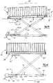
Fig. 9 befindlichen Stellvorrichtung in manuell bedienbarer Ausführung, - Fig. 12 bis Fig. 17
- jeweilige Seitenansichten unterschiedlicher Ausführungen und Bedienstellungen im Bereich der Stellvorrichtung und der kippbaren Bodenwandung gemäß
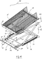
Fig. 11 , - Fig. 18
- eine perspektivische Einzeldarstellung der Stellvorrichtung gemäß
Fig. 11 mit integriertem Feder-Dämpfer-System, - Fig. 19
- eine perspektivische Einzeldarstellung ähnlich
Fig. 18 mit zwei Antriebs-Zylindern im Bereich der Stellvorrichtung, - Fig. 20 und Fig. 21
- jeweilige Darstellungen ähnlich
Fig. 9 und Fig. 10 mit einer zusätzlichen Hubfeder im Bereich der beiden Stellvorrichtungen der geteilten Bodenwandung, - Fig. 22 bis Fig. 25
- eine Ausführung des Stützsystems ähnlich
Fig. 5 bis Fig. 8 mit nur einem Führungsritzel, und - Fig. 26 bis Fig. 28
- eine Ausführung der bodenseitigen Stellvorrichtung ähnlich
Fig. 18 mit Fußstellhebel an einem Gasdruckdämpfer. - In
Fig. 1 ist ein insgesamt mit 1 bezeichneter Verkaufs- und Transportbehälter zur Warenpräsentation in Supermärkten o. dgl. Verkaufseinrichtungen dargestellt. Der Behälter 1 ist mit jeweiligen paarweise gegenüberliegenden vertikalen Längs- und Querseitenwänden 2, 3, 4, 5 versehen, die vorzugsweise im Bereich von eckseitigen Stützpfosten 6, 7, 8, 9 verbunden sind. Dieser nach Art eines Gittertisches aufgebaute Behälter 1 definiert dabei einen Nutzraum N, in den zumindest eine die nicht näher dargestellten Waren entnahmegerecht untergreifende Bodenwandung 10 einbringbar ist. Bei gattungsbildenden Ausführungen derartiger Gittertische ist bereits vorgesehen, dass die Bodenwandung 10 zumindest in unbeladenem Zustand in unterschiedliche Gebrauchsstellungen verlagert und in diesen fixiert werden kann. Davon ausgehend sieht das erfindungsgemäße Konzept der Behälterkonstruktion vor, dass nunmehr die Bodenwandung 10 mit zumindest einer diese verlagerbar aufnehmenden Stellvorrichtung 11 (Fig. 2 ) verbunden werden kann. - Die Konstruktion ist dabei so ausgeführt, dass die mit der Stellvorrichtung 11 verbundene Bodenwandung 10 wahlweise von Hand, per Fuß und/oder mittels zumindest eines Stellorgans 12 (
Fig. 13 ) verlagerbar ist. Das Konzept einer mittels der Stellvorrichtung 11 verlagerbaren Bodenwandung 10 ist darauf gerichtet, dass für abzustützende Waren zumindest im Bereich einer offenen Oberseite 13 des Nutzraumes N variable Zugriffs- und Gebrauchsstellungen vorgegeben werden können. - In den Darstellungen gemäß
Fig. 2 bis Fig. 8 ist als Grundlage des erfindungsgemäßen Stell-Prinzips ein direkt einsetzbares Hubsystem an der Bodenwandung 10 veranschaulicht. Dabei wird von einem Konzept ausgegangen, bei dem die mit der Bodenwandung verbindbare Stellvorrichtung 11 mit mehreren - unmittelbar an der Bodenwandung 10 angreifenden - Stellgliedern SG zusammenwirkt. Diese Stellglieder SG können sowohl im Bereich der Behälterwandung (nicht näher dargestellt) als auch im Bereich zumindest eines Stützpfostens 7, 8 (Fig. 3, Fig. 4 ) gehalten sein. - In
Fig. 2 ist ein Prinzipbild gezeigt, wobei das System in jeweiligen Eckbereichen der Bodenwandung 10 eines der Stellglieder SG aufweist, die als Stellvorrichtung 11 wirken. In zweckmäßiger Ausführung sind zumindest im Bereich paarweise zusammenwirkender Stellglieder SG als Kraftspeicher jeweilige Druckfedern 14 vorgesehen, die in einer vertikalen Vorspannrichtung gemäß Pfeil D (Fig. 2 ) so vorgespannt werden können, dass die Stellglieder SG insgesamt eine "innere Vorspannkraft" aufweisen und damit die Bodenwandung 10 beaufschlagt werden kann. - In einer Ausführung gemäß
Fig. 3 bis Fig. 8 ist diese Einbaulage der Bodenwandung 10 in Verbindung mit den eine jeweilige Druckfeder 14 aufweisenden Stellgliedern SG dargestellt. Dabei ist vorgesehen, dass im Bereich des Stellgliedes SG jeweils ein oberes Führungsritzel 15 und ein mit der Bodenwandung 10 schwenkbar verbindbares Bremsritzel 16 zusammenwirken (Pfeil A, A';Fig. 6 ). Diese beiden Ritzel 15 und 16 können in eine jeweilige Profilierung zweier paralleler Zahnstangen 17, 17' so eingreifen, dass in der Einbaulage gemäßFig. 5 eine Bremswirkung und damit Fixierung der Bodenwandung 10 mittels eines verlagerbaren Rastbolzens RB erreicht wird. - Bei Ausführung einer in
Fig. 6 dargestellten Kippbewegung um einen Winkel A werden das Bremsritzel 16 und der Rastbolzen RB aus ihrer Verbindungslage im Bereich der Zahnstange 17, 17' gelöst. Das Bremsritzel 16 gelangt in parallelem Abstand zum oberen Ritzel 15 in Eingriffslage an der Zahnstange 17, 17'. Damit erfolgt gleichzeitig eine Freigabe der bisher gebremsten Vorspannkraft im Bereich der Druckfeder 14, so dass eine Verlagerung der Bodenwandung 10 in vertikaler Richtung gemäß Pfeil B möglich ist. Für den Fall, dass durch ein Gewicht und/oder die Handkraft eines Bedieners eine Gegenkraft C auf die Bodenwandung 10 aufgebracht wird, kann das System in Absenkrichtung gemäß Pfeil B' verlagert werden, wobei ein Vorspannen der Druckfeder 14 erfolgt (Pfeil D,Fig. 2 ). - Durch die Rückverlagerung der Bodenwandung 10 in Pfeilrichtung A' werden das Bremsritzel 16 und der Rastbolzen RB wieder in ihrer Bremslage an der Zahnstange 17, 17' fixiert. Aus den Darstellungen gemäß
Fig. 7 und Fig. 8 sind die Eingriffsbedingungen im Bereich der beiden Ritzel 15 und 16 im Zusammenhang mit den beiden Zahnstangen 17 und 17' näher verdeutlicht. Mit diesen Ausführungsformen gemäßFig. 2 bis Fig. 8 wird eine direkte Abstützung der Bodenwandung 10 an strukturellen Teilen des nur schematisch dargestellten Gittertisches 1 deutlich. - Eine ähnliche Konstruktion ist in
Fig. 22 bis Fig. 25 als eine zweite Ausführung zum direkten Verstellen der Bodenwandung 10 dargestellt. Diese von Hand ausführbare Einstellung des Systems (Pfeil B) ist hier dadurch möglich, dass in den beiden parallelen C-Profilen CP (Fig. 22 ) jeweils ein Zahnstangen-Profil 17" (Fig. 25 ) vorgesehen wird. Dabei kann eine Kippung gemäß Pfeil A (Fig. 6 ) ausgeführt werden, so dass in der den Haltebolzen HB aus den Stecköffnungen SG entriegelnden Schräglage die Verlagerung des Bodens 10 in Pfeilrichtung B möglich ist. Dabei wird ein in zweckmäßiger Ausführung rollenförmiges Anlageteil AG im C-Profil CP so geführt, dass eine benutzerfreundlich geführte Verlagerung des Bodens 10 möglich ist und das Ritzel 16 definiert in der Zahnstange 17" abrollen kann. - Eine zweite Ausführung der Bodenwandung-Stellvorrichtung-Kombination sieht vor, dass vorzugsweise ein - aus den Prinzipdarstellungen in
Fig. 9 bis Fig. 18 ersichtlicher - Scherenarmheber 18 als Stellvorrichtung 11 eingesetzt wird. An dieser Ausführungsform wird deutlich, dass die zumindest bereichsweise eine zur Horizontalen H - in einem Aufstellraum - parallele Nutzfläche E bildende Bodenwandung 10 mittels der Stellvorrichtung 11 in unterschiedliche Höhenlagen F, F' (Fig. 16, Fig. 17 ) innerhalb des Nutzraumes N festlegbar ist. - Eine Zusammenschau von
Fig. 12 und Fig. 13 zeigt dabei, dass die Bodenwandung 10 im oberen Bereich der Stellvorrichtung 11 kippbar gehalten ist. Damit wird erreicht, dass die zumindest an der Oberseite 13 des Nutzraumes N offen zugängliche Ware (nicht dargestellt) auf einer zumindest bereichsweise schräggestellten Nutzfläche E' präsentiert werden kann. Bei dieser Variante der Kippbewegung gemäß Pfeil KB kann die Bodenwandung 10 um einen Stützpunkt SP geschwenkt werden, wozu die Anwendung eines - hier unabhängig von der Stellvorrichtung 11 wirksamen - Stellorgans 12 denkbar ist. In der oberen Kippstellung gemäßFig. 13 ist eine Fixierung der Bodenwandung 10 im Bereich des Stellorgans 12 oder mittels einer mechanischen Verriegelung (nicht dargestellt) denkbar. - Für das Gesamtkonzept des Gittertisch-Systems 1 ist vorgesehen, dass die zumindest bereichsweise horizontal verlaufende oder gekippte Gebrauchsstellungen einnehmende Bodenwandung 10 mit variablen Stellsystemen kombiniert werden kann. Diese sind so aufgebaut, dass jeweils eine gestufte oder stufenlose Verlagerung und Positionierung der Komponenten denkbar ist.
- Ausgehend von einer geschnittenen Darstellung des Behälters 1 in
Fig. 9 - hier ohne Seitenwände 2, 3 - wird deutlich, dass die Bodenwandung 10 auch eine mehrteilige Nutzfläche E aufweisen kann. Dargestellt sind hier zumindest zwei Teilbereiche T und T' (Fig. 9 ), wobei diese mittels zumindest einer jeweiligen Stellvorrichtung 11 einzeln verlagerbar sind. Denkbar ist dabei auch, dass die beiden Teilbereiche T, T' eine gemeinsame Stellvorrichtung aufweisen (nicht dargestellt). - In vorteilhafter Ausführung ist das vorbeschriebene System aus Bodenwandung 10 und Stellvorrichtung 11 in konstruktiv einfacher und für den Einsatz optimaler Gestaltung als eine autarke Baueinheit BE ausführbar. Ausgehend von der in
Fig. 1 dargestellten kompakten Integration der Baugruppen in die Wand-Pfosten-Konstruktion eines Gittertisches 1 ist in dessen Wandstruktur auch eine selbstständige modulare Baueinheit BE - gemäßFig. 11 ,Fig. 18 ,Fig. 19 - einsetzbar. - Denkbar ist dabei, dass die autarke Baueinheit BE auch ohne umgebende Baugruppen (
Fig. 9 ,Fig. 20 ) in einer direkt auf dem Boden H eines Aufstellraumes R aufliegenden Gebrauchslage festgelegt wird (nicht dargestellt). Damit ist eine Anwendung denkbar, bei der an sich bekannte Gittertische durch die autarke Baueinheit BE umgerüstet werden können und damit die verlagerbare Bodenwandung 10 auch in vorhandene Systeme integrierbar ist. - Die optimale Umsetzung dieser Baueinheit BE und einer Grundstruktur gemäß
Fig. 11 sieht erfindungsgemäß vor, dass die auf der Stellvorrichtung 11 befindliche Bodenwandung 10 als funktionale Baugruppe - an Stelle einer direkten Bodenauflage - an den Bauteilen BR, BR' des an sich bekannten Gittertisches 1 in einer rahmenseitigen Verbindungslage festgelegt werden kann. Dieses Konzept mit rahmenintegrierter Stellvorrichtung 11 wird anhand der Darstellungen gemäßFig. 11 bis Fig. 21 in detaillierten Varianten näher beschrieben. - Ausgehend von der in
Fig. 11 gezeigten Konstruktion mit dem als Stellvorrichtung 11 ausgebildeten Scherenarmheber 18 wird deutlich, dass dieser mit zumindest zwei durch ein zentrales Stützgelenk 19 verbundenen Scherenarmen 20, 21 versehen ist. In an sich bekannter Ausführung derartiger Systeme ist auch hier vorgesehen, dass den Scherenarmen 20, 21 mittels einer an sich bekannten Festlager-Loslager-Abstützung mit Festlagern 22, 22' und Loslagern 23, 23' unterschiedliche Spreizstellungen vermittelbar sind und damit eine Veränderung jeweiliger Höhenlagen F, F' der an den oberen Enden der Scherenarme 20, 21 befindlichen Bodenwandung 10 erreichbar sind (Fig. 9, Fig. 10 ). - In
Fig. 11 wird die zweckmäßige Ausführung des Scherenarmhebers deutlich, wobei dieser an den parallelen Seitenrändern 25, 25' der Bodenwandung 10 einen jeweiligen Teil-Scherenarmheber 18 aufweist, derart, dass die Bodenwandung 10 mittels paarweise gegenüberliegender Scherenarme 20, 20' und 21, 21' bodenparallel verlagerbar ist (Pfeil FF;Fig. 19 ). - Die konstruktive Umsetzung dieses Systems für die verlagerbare Bodenwandung 10 sieht vor, dass die jeweiligen Loslager 23, 23' der Scherenarme 20, 20' und 21, 21' einerseits im Bereich eines unteren Gestellrahmens 26 mittels einer in eine Rastführung 27 eingreifenden Verbindungsstrebe 28 in unterschiedlichen Spreizstellungen festlegbar sind (
Fig. 14 bis Fig. 17 ; Höhenlage F, F'). Dazu ist vorgesehen, dass andererseits im Bereich der oberen Bodenwandung 10 eine das Loslager 24, 24' des jeweiligen Scherenarms 20, 20' bildende Längsnut 29, 29' als Längsführung wirksam ist. - Die weitere Gestaltung dieser Baugruppen sieht vor, dass der als Stellvorrichtung 11 vorgesehene Scherenarmheber 18 unterhalb der Bodenwandung 10 mit einem die oberen Enden der Scherenarm-Paare im Bereich der oberen Loslager 24, 24' und der Festlager 22", 22''' erfassenden Tragrahmen 30 versehen ist. Damit wird es möglich, dass auf diesem Tragrahmen 30 die Hub- und/oder Kippverstellung der Bodenwandung 10 mittels des zumindest einen Stellorgans 12 (
Fig. 13 ) realisiert werden kann. - In
Fig. 14 und Fig. 15 sind die Eingriffsbedingungen im Bereich der Loslager 23, 24 (23', 24') verdeutlicht, wobei durch eine Kombination der in der Längsnut 29' einstellbaren Position des einen Scherenarms 20 mit dem im Bereich der Rastführung 27 eingreifenden anderen Scherenarm 21 dazu genutzt werden kann, die Bodenwandung 10 in eine die Auflageebene E" bildende Neigungsposition KB' (Fig. 14 ) zu verlagern. - Für die Unterstützung der insbesondere von Hand ausführbaren vorbeschriebenen Stell- und Kippbewegungen F, F', KB, KB' sind im Bereich des unteren Gestellrahmens 26 weitere Baugruppen denkbar. Neben der Nutzung unterschiedlicher Stellpositionen im Bereich der Rastführung 27 (
Fig. 14 bis Fig. 17 ) ist eine zusätzliche Baugruppe in Form eines Dämpfers 31 (Fig. 18 ) denkbar. Dabei ist vorgesehen, dass in dieses System äußere Federteile 32 integriert sind, mit denen die jeweilige Stützposition im Bereich der Rastführung 27, 27' fixiert werden kann (Fig. 12, Fig. 13 ). - Zum Lösen dieser formschlüssigen Fixierung bei 27, 27' ist zumindest eine Fußraste 33 mit Haltehaken 33' und Rückstellfeder 33" in den Gestellrahmen 26 integriert. Mittels eines Bügels VB ist eine Verbindung zwischen den beiden Rastführungen 27 und 27' hergestellt (
Fig. 18 ). - In der Ausführung gemäß
Fig. 19 ist - an Stelle der Rastführung 27,Fig. 11 - eine untere Führungsnut 34, 34' für die untere Verbindungsstrebe 28 im Bereich der Loslager vorgesehen. Dieses System ist mit zwei am unteren Gestellrahmen 26 gehaltenen Zylindern 35, 36 (Bewegungspfeil Z) versehen. Mit diesen als Stelleinheit vorgesehenen Zylindern 35, 36 kann die stufenlose Verstellung im Bereich der Scherenarme 20, 20', 21, 21' ausgelöst werden (Pfeil FF), so dass die Bodenwandung 10 motorisch in eine vorgesehene Gebrauchslage bewegt wird. - In
Fig. 20 und Fig. 21 ist eine weitere Ergänzung des vorbeschriebenen Systems 1 mit den zwei parallelen Scherenarmpaaren des Hebers 18 dargestellt (ähnlichFig. 9 und Fig. 10 ). Dabei sind unterhalb der mit den Scherenarmheber-Stellvorrichtungen zusammenwirkenden Bodenwandung 10 zusätzliche Hubfedern 37 angeordnet. Mit diesen kann das (im Wesentlichen mit den gezeigten Ausführungen gemäßFig. 9 bis Fig. 19 vergleichbare) Scherenarm-System weitgehend selbsttätig nach Aufbringen einer Vorspannung - beispielsweise durch ein aufliegendes Gewicht gemäß Pfeil C' - bewegt werden (Pfeil D'), so dass eine bei Entnahme von Waren effektive Hubunterstützung (Pfeil FF') in den Gittertisch 1 integriert ist. - Eine optimale Be- und Entladeposition für den Gittertisch 1 mit verlagerbarer Bodenwandung 10 kann dadurch erreicht werden, dass zumindest eine der den Nutzraum N begrenzenden Seitenwände (hier: Wand 2,
Fig. 1 ) in eine Öffnungsstellung verlagerbar ist, so dass durch Absenken der oberen Teilwand TW die in einer "niedrigen Position" befindliche Bodenwandung 10 erreichbar wird und damit die bei der Beladung oder Entnahme zu überwindenden Zugangshöhe ZH gering gehalten werden kann (ZH', ZH"). - In
Fig. 26 bis Fig. 28 ist eine zweite Ausführung der Baueinheit BE ähnlichFig. 18 mit der Rast-Verstellung im Bereich der Fußraste 33 (Fig. 18 ) dargestellt. Dieses System weist eine zentrale Gasdruckfeder 38 auf, die mit dem bodenseitigen Stellsystem zusammenwirkt. Die Fußraste 33 ist über ein Querrohr 39 mit den beiden federbelasteten Rastträgern 40, 40' verbunden. Bei Betätigung der Fußraste 33 erfolgt jeweils eine Entriegelung im Bereich einer Profilnut 41, indem die Querstange 42 des Scherenarmträgers in die Position gemäßFig. 28 gelangt. Damit wird in Pfeilrichtung RS eine Verlagerung zur nächsten der Profilnuten 41 hin möglich. - Diese Bedienmechanik im Bereich der Rastträger 40 ist dabei jeweils mit einer schwenkgesteuerten Längsstrebe 43 versehen, die endseitige Steuerschenkel 44, 45 aufweist, deren Führungsbolzen 46, 47 in einen jeweiligen Nutbogen 48, 49 eingreift. Der eine Stützrolle 50 aufweisende Scherenarm 21 ist dabei jeweils in einem Hohlprofilträger 51 gehalten, so dass eine besonders einfache Höhenverstellung der Baueinheit BE möglich ist.
Claims (21)
- Verkaufs- und Transportbehälter zur Warenpräsentation, mit jeweiligen paarweise gegenüberliegenden vertikalen Längs- und Querseitenwänden (2, 3, 4, 5), die vorzugsweise im Bereich von eckseitigen Stützpfosten (6, 7, 8, 9) verbunden sind, so dass der nach Art eines Gittertisches aufgebaute Behälter (1) einen Nutzraum (N) aufweist, in diesen zumindest eine die Waren entnahmegerecht untergreifende Bodenwandung (10) einbringbar ist und diese zumindest in unbeladenem Zustand in unterschiedlichen Gebrauchsstellungen positionierbar ist, dadurch gekennzeichnet, dass die Bodenwandung (10) mit zumindest einer diese verlagerbar aufnehmenden Stellvorrichtung (11) verbindbar ist.
- Verkaufs- und Transportbehälter nach Anspruch 1, dadurch gekennzeichnet, dass die mit der Stellvorrichtung (11) verbundene Bodenwandung (10) von Hand, per Fuß und/oder mittels zumindest einer als Stellorgan aktivierbaren Baugruppe (SG, 12, 31, 32, 35, 36, 37) verlagerbar ist.
- Verkaufs- und Transportbehälter nach Anspruch 1 oder 2, dadurch gekennzeichnet, dass mittels der verlagerbaren Bodenwandung (10) für abzustützende Waren zumindest im Bereich einer offenen Oberseite (13) des Nutzraumes (N) variable Zugriffs- und Gebrauchsstellungen vorgebbar sind.
- Verkaufs- und Transportbehälter nach einem der Ansprüche 1 bis 3, dadurch gekennzeichnet, dass die zumindest bereichsweise eine zur Horizontalen (H) in einem Aufstellraum (R) parallele Nutzfläche (E) bildende Bodenwandung (10) mittels der Stellvorrichtung (11) in unterschiedlichen Höhenlagen (F, F') innerhalb des Nutzraumes (N) festlegbar ist.
- Verkaufs- und Transportbehälter nach einem der Ansprüche 1 bis 4, dadurch gekennzeichnet, dass die Bodenwandung (10) im Bereich der Stellvorrichtung (11) kippbar gehalten ist, derart, dass die zumindest von der Oberseite (13) des offenen Nutzraumes (N) erreichbaren Waren auf einer zumindest bereichsweise schräggestellten Nutzfläche (E', E") präsentierbar sind.
- Verkaufs- und Transportbehälter nach einem der Ansprüche 1 bis 5, dadurch gekennzeichnet, dass die zumindest bereichsweise parallel zur Horizontalen (H) verlaufende oder gekippte Gebrauchsstellungen einnehmende Bodenwandung (10) gestuft oder stufenlos verlagerbar ist.
- Verkaufs- und Transportbehälter nach einem der Ansprüche 1 bis 6, dadurch gekennzeichnet, dass die Bodenwandung (10) eine mehrteilige Nutzfläche aufweist und die zumindest zwei Teilbereiche (T, T') mittels der zumindest einen Stellvorrichtung (11) einzeln verlagerbar sind.
- Verkaufs- und Transportbehälter nach Anspruch 7, dadurch gekennzeichnet, dass beide Teilbereiche (T, T') der geteilten Bodenwandung (10) mit jeweils einer Stellvorrichtung (11) versehen sind.
- Verkaufs- und Transportbehälter nach einem der Ansprüche 1 bis 8, dadurch gekennzeichnet, dass das zumindest eine System aus Bodenwandung (10) und Stellvorrichtung (11) als eine autarke Baueinheit (BE) unabhängig vom Gittertisch (1) einsetzbar ist.
- Verkaufs- und Transportbehälter nach Anspruch 9, dadurch gekennzeichnet, dass die autarke Baueinheit (BE) in einer auf dem Boden (H) des Aufstellraumes (R) aufliegenden Gebrauchslage festlegbar ist.
- Verkaufs- und Transportbehälter nach Anspruch 9, dadurch gekennzeichnet, dass die autarke Baueinheit (BE) eine in oder an den Bauteilen (26) des Gittertisches (1) festlegbare Gebrauchslage aufweist.
- Verkaufs- und Transportbehälter nach einem der Ansprüche 1 bis 11, dadurch gekennzeichnet, dass die Stellvorrichtung (11) als ein die Bodenwandung (10) untergreifender Scherenarmheber (18) mit zumindest zwei durch ein zentrales Stützgelenk (19) verbundenen Scherenarmen (20, 21, 20', 21') ausgebildet ist, derart, dass den Scherenarmen (20, 21, 20', 21') mittels einer an sich bekannten Festlager-Loslager-Abstützung (bei 22, 22'; 23, 23'; 24, 24') eine Verlagerung in unterschiedliche Spreizstellungen vermittelbar ist und damit eine Veränderung jeweiliger Höhenlagen (F, F') der an den oberen Enden der Scherenarme (20, 21, 20', 21') befindlichen Bodenwandung (10) erreichbar ist.
- Verkaufs- und Transportbehälter nach Anspruch 12, dadurch gekennzeichnet, dass an den parallelen Seitenrändern (25, 25') der Bodenwandung (10) ein jeweiliger Scherenarmheber (18) vorgesehen ist, derart, dass die Bodenwandung (10) mittels paarweise gegenüberliegender Scherenarme (20, 21, 20', 21') bodenparallel verlagerbar ist.
- Verkaufs- und Transportbehälter nach Anspruch 12 oder 13, dadurch gekennzeichnet, dass die jeweiligen Loslager (23, 23', 24, 24') der Scherenarme (20, 21, 20', 21') einerseits im Bereich eines unteren Gestellrahmens (26) mittels einer in einer Rastführung (27, 27') eingreifenden Verbindungsstrebe (28) in unterschiedlichen Spreizstellungen festlegbar sind und andererseits im Bereich der oberen Bodenwandung (10) eine das Loslager (24, 24') des Scherenarms (20, 20') aufnehmende Längsnut (29, 29') vorgesehen ist.
- Verkaufs- und Transportbehälter nach einem der Ansprüche 12 bis 14, dadurch gekennzeichnet, dass der als Stellvorrichtung (11) vorgesehene Scherenarmheber (18) unterhalb der Bodenwandung (10) mit einem die oberen Enden der Scherenarm-Paare im Bereich der Loslager und der Festlager erfassenden Tragrahmen (30) versehen ist, derart, dass entweder auf diesem Tragrahmen (30) die Hub- und/oder Kippverstellung der Bodenwandung (10) mittels zumindest eines Stellorgans (12) ausführbar ist oder der Tragrahmen (30) insgesamt in eine Kippstellung (KB') verlagerbar ist.
- Verkaufs- und Transportbehälter nach einem der Ansprüche 1 bis 7, dadurch gekennzeichnet, dass die mit der Bodenwandung (10) verbindbare Stellvorrichtung (11) mit zumindest einem unmittelbar an der Bodenwandung (10) angreifenden Stellglied (SG) versehen ist.
- Verkaufs- und Transportbehälter nach Anspruch 16, dadurch gekennzeichnet, dass das Stellglied (SG) im Bereich der Behälterwände (2, 3, 4, 5) und/oder der Stützpfosten (6, 7, 8, 9) gehalten ist.
- Verkaufs- und Transportbehälter nach Anspruch 16 oder 17, dadurch gekennzeichnet, dass im Bereich der Stützpfosten (6, 7, 8, 9) jeweils ein einen Kraftspeicher aufweisendes Stellglied (SG) vorgesehen ist.
- Verkaufs- und Transportbehälter nach Anspruch 18, dadurch gekennzeichnet, dass als Kraftspeicher eine vorspannbare Druckfeder (14) vorgesehen ist, die in vertikaler Einbaulage ein oberes Führungsritzel (15) und ein Bremsritzel (16) aufweist, derart, dass diese Ritzel (15, 16) mit einer jeweiligen im Stützpfosten (6, 7, 8, 9) vorgesehenen Zahnstange (17, 17') verbindbar ist und damit eine geführte Hubverlagerung (Pfeil B, B') für die Bodenwandung (10) ausgelöst und gebremst werden kann.
- Verkaufs- und Transportbehälter nach einem der Ansprüche 1 bis 19, dadurch gekennzeichnet, dass zumindest eine der den Nutzraum (N) begrenzenden Seitenwände (2, 3, 4, 5) in eine Öffnungsstellung verlagerbar ist.
- Verkaufs- und Transportbehälter nach Anspruch 20, dadurch gekennzeichnet, dass zumindest eine der Seitenwände (2, 3, 4, 5) aus zumindest zwei Teilwänden (TW, TW') gebildet ist, von denen zumindest eine in eine Öffnungsstellung verlagerbar ist.
Priority Applications (1)
| Application Number | Priority Date | Filing Date | Title |
|---|---|---|---|
| PL18159163T PL3369348T3 (pl) | 2017-03-01 | 2018-02-28 | Pojemnik do sprzedaży i transportu do prezentacji towarów |
Applications Claiming Priority (1)
| Application Number | Priority Date | Filing Date | Title |
|---|---|---|---|
| DE202017001134.4U DE202017001134U1 (de) | 2017-03-01 | 2017-03-01 | Verkaufs- und Transportbehälter zur Warenpräsentation |
Publications (2)
| Publication Number | Publication Date |
|---|---|
| EP3369348A1 true EP3369348A1 (de) | 2018-09-05 |
| EP3369348B1 EP3369348B1 (de) | 2020-10-28 |
Family
ID=61526599
Family Applications (1)
| Application Number | Title | Priority Date | Filing Date |
|---|---|---|---|
| EP18159163.7A Active EP3369348B1 (de) | 2017-03-01 | 2018-02-28 | Verkaufs- und transportbehälter zur warenpräsentation |
Country Status (4)
| Country | Link |
|---|---|
| EP (1) | EP3369348B1 (de) |
| DE (1) | DE202017001134U1 (de) |
| ES (1) | ES2846306T3 (de) |
| PL (1) | PL3369348T3 (de) |
Families Citing this family (3)
| Publication number | Priority date | Publication date | Assignee | Title |
|---|---|---|---|---|
| WO2020030381A1 (de) | 2018-08-06 | 2020-02-13 | Wanzl Metallwarenfabrik Gmbh | Verkaufstisch |
| DE102018123584A1 (de) | 2018-09-25 | 2020-03-26 | Wanzl GmbH & Co. KGaA | Trennwandelement für einen Verkaufstisch sowie Verkaufstisch |
| FR3103801B1 (fr) * | 2019-11-29 | 2022-01-14 | Pa Cotte Sa | Colis comprenant des moyens de retenue d’un objet |
Citations (14)
| Publication number | Priority date | Publication date | Assignee | Title |
|---|---|---|---|---|
| US1640405A (en) * | 1927-02-21 | 1927-08-30 | Union Steel Prod Co | Display receptacle |
| US3663078A (en) * | 1970-10-19 | 1972-05-16 | Insulating Fabricators Inc | Receptacle and improved floating platform therefor |
| DE7628135U1 (de) | 1976-09-08 | 1977-01-27 | Erni Max | Behaelter |
| DE2841772A1 (de) | 1977-09-27 | 1979-04-05 | Gerardus Cornelis Brinkers | Behaelter zum verpacken, ausstellen und anbieten von waren |
| WO1998035594A1 (en) * | 1997-02-13 | 1998-08-20 | Herman Miller, Inc. | Shelf with movable barrier |
| WO2004078003A1 (en) * | 2003-03-03 | 2004-09-16 | Talon Customizing House Limited | Pallet retail merchandising apparatus and method therefor |
| EP1511411B1 (de) | 2002-06-11 | 2005-10-26 | Wanzl Metallwarenfabrik Gmbh | Tisch für selbstbedienungsgeschäfte |
| EP1640281A1 (de) | 2004-09-18 | 2006-03-29 | Heinrich J. Kesseböhmer KG | Zusammenlegbarer Verkaufs- und Transportbehälter |
| DE202005006085U1 (de) | 2005-04-16 | 2006-08-31 | Heinrich J. Kesseböhmer KG | Gittertisch zur Warenpräsentation |
| WO2010012929A1 (fr) * | 2008-07-28 | 2010-02-04 | Caddie | Table a paroi de fond a crochets |
| DE202009006757U1 (de) | 2009-05-11 | 2010-09-23 | Heinrich J. Kesseböhmer KG | Gittertisch zur Warenpräsentation |
| DE202009006756U1 (de) | 2009-05-11 | 2010-09-23 | Heinrich J. Kesseböhmer KG | Gittertisch zur Warenpräsentation |
| DE202010003310U1 (de) | 2010-03-09 | 2011-09-09 | Heinrich J. Kesseböhmer KG | Zusammenlegbarer Verkaufsbehälter in Form eines Gittertisches |
| DE202013009631U1 (de) | 2013-10-31 | 2013-12-04 | Kesseböhmer Holding e.K. | Verkaufs- und Transportbehälter zur Warenpräsentation |
Family Cites Families (3)
| Publication number | Priority date | Publication date | Assignee | Title |
|---|---|---|---|---|
| US2717085A (en) * | 1950-10-20 | 1955-09-06 | American Mach & Foundry | Self-leveling, storing and dispensing apparatus |
| FR2633589B1 (fr) * | 1988-06-29 | 1991-04-12 | Safil | Conteneur presentoir |
| US20040000260A1 (en) * | 2002-06-28 | 2004-01-01 | Michael Connor | Portable cradle |
-
2017
- 2017-03-01 DE DE202017001134.4U patent/DE202017001134U1/de active Active
-
2018
- 2018-02-28 ES ES18159163T patent/ES2846306T3/es active Active
- 2018-02-28 PL PL18159163T patent/PL3369348T3/pl unknown
- 2018-02-28 EP EP18159163.7A patent/EP3369348B1/de active Active
Patent Citations (14)
| Publication number | Priority date | Publication date | Assignee | Title |
|---|---|---|---|---|
| US1640405A (en) * | 1927-02-21 | 1927-08-30 | Union Steel Prod Co | Display receptacle |
| US3663078A (en) * | 1970-10-19 | 1972-05-16 | Insulating Fabricators Inc | Receptacle and improved floating platform therefor |
| DE7628135U1 (de) | 1976-09-08 | 1977-01-27 | Erni Max | Behaelter |
| DE2841772A1 (de) | 1977-09-27 | 1979-04-05 | Gerardus Cornelis Brinkers | Behaelter zum verpacken, ausstellen und anbieten von waren |
| WO1998035594A1 (en) * | 1997-02-13 | 1998-08-20 | Herman Miller, Inc. | Shelf with movable barrier |
| EP1511411B1 (de) | 2002-06-11 | 2005-10-26 | Wanzl Metallwarenfabrik Gmbh | Tisch für selbstbedienungsgeschäfte |
| WO2004078003A1 (en) * | 2003-03-03 | 2004-09-16 | Talon Customizing House Limited | Pallet retail merchandising apparatus and method therefor |
| EP1640281A1 (de) | 2004-09-18 | 2006-03-29 | Heinrich J. Kesseböhmer KG | Zusammenlegbarer Verkaufs- und Transportbehälter |
| DE202005006085U1 (de) | 2005-04-16 | 2006-08-31 | Heinrich J. Kesseböhmer KG | Gittertisch zur Warenpräsentation |
| WO2010012929A1 (fr) * | 2008-07-28 | 2010-02-04 | Caddie | Table a paroi de fond a crochets |
| DE202009006757U1 (de) | 2009-05-11 | 2010-09-23 | Heinrich J. Kesseböhmer KG | Gittertisch zur Warenpräsentation |
| DE202009006756U1 (de) | 2009-05-11 | 2010-09-23 | Heinrich J. Kesseböhmer KG | Gittertisch zur Warenpräsentation |
| DE202010003310U1 (de) | 2010-03-09 | 2011-09-09 | Heinrich J. Kesseböhmer KG | Zusammenlegbarer Verkaufsbehälter in Form eines Gittertisches |
| DE202013009631U1 (de) | 2013-10-31 | 2013-12-04 | Kesseböhmer Holding e.K. | Verkaufs- und Transportbehälter zur Warenpräsentation |
Also Published As
| Publication number | Publication date |
|---|---|
| PL3369348T3 (pl) | 2021-06-14 |
| EP3369348B1 (de) | 2020-10-28 |
| DE202017001134U1 (de) | 2018-06-04 |
| ES2846306T3 (es) | 2021-07-28 |
Similar Documents
| Publication | Publication Date | Title |
|---|---|---|
| EP1674372B1 (de) | Verkaufs- und Transportbehälter zur Warenpräsentation | |
| DE102009002613A1 (de) | Scherenhebebühne | |
| EP2850968B1 (de) | Stückgutlager | |
| EP3369348A1 (de) | Verkaufs- und transportbehälter zur warenpräsentation | |
| DE102007021159A1 (de) | Rostdeckenschalung zur Einbindung einer Säule | |
| EP2614028B1 (de) | Vorrichtung zur aufnahme eines gabelträgerprofils | |
| DE3515260A1 (de) | Kragarmregal fuer schwere lasten | |
| DE102004063580A1 (de) | Möbelstück mit bewegbarem Möbelsegment | |
| DE3638506C1 (de) | Fahrwerk fuer eine verfahrbare Tribuene | |
| EP3369671B1 (de) | Verkaufs- und transportbehälter zur warenpräsentation | |
| EP0960849B1 (de) | Hubvorrichtung, insbesondere Hebebühne für Kraftfahrzeuge | |
| EP0935932B1 (de) | Lagerregal, vorzugsweise für die Lagerung bestückter Paletten | |
| WO2021105197A1 (de) | Möbelbausatz | |
| DE202016001602U1 (de) | Hebevorrichtung | |
| EP3456220A1 (de) | Arbeitsplatzsystem mit flexibler montagefläche | |
| DE2012773C2 (de) | Kleinhebegerät | |
| DE10223599B4 (de) | Container | |
| DE102018001904B4 (de) | Verkaufs- und Transportbehälter zur Bevorratung und Präsentation von Waren | |
| DE102016002924A1 (de) | Hebevorrichtung | |
| DE202004011443U1 (de) | Abstützvorrichtung für Traggestelle mit vorkragenden Lasten | |
| EP0749826A2 (de) | Mechanische Kniehebelpresse | |
| CH716838A1 (de) | Traverse, Traversensatz und Möbelbausatz. | |
| EP2446774B1 (de) | Höhenverstellvorrichtung sowie höhenverstellbarer Tisch | |
| DE3537804C2 (de) | Gestänge für eine Ausziehplatte | |
| AT6953U2 (de) | Hubgerät für den feuerwehreinsatz |
Legal Events
| Date | Code | Title | Description |
|---|---|---|---|
| PUAI | Public reference made under article 153(3) epc to a published international application that has entered the european phase |
Free format text: ORIGINAL CODE: 0009012 |
|
| STAA | Information on the status of an ep patent application or granted ep patent |
Free format text: STATUS: THE APPLICATION HAS BEEN PUBLISHED |
|
| AK | Designated contracting states |
Kind code of ref document: A1 Designated state(s): AL AT BE BG CH CY CZ DE DK EE ES FI FR GB GR HR HU IE IS IT LI LT LU LV MC MK MT NL NO PL PT RO RS SE SI SK SM TR |
|
| AX | Request for extension of the european patent |
Extension state: BA ME |
|
| STAA | Information on the status of an ep patent application or granted ep patent |
Free format text: STATUS: REQUEST FOR EXAMINATION WAS MADE |
|
| 17P | Request for examination filed |
Effective date: 20190305 |
|
| RAV | Requested validation state of the european patent: fee paid |
Extension state: MD Effective date: 20190305 |
|
| RAX | Requested extension states of the european patent have changed |
Extension state: BA Payment date: 20190305 Extension state: ME Payment date: 20190305 |
|
| RBV | Designated contracting states (corrected) |
Designated state(s): AL AT BE BG CH CY CZ DE DK EE ES FI FR GB GR HR HU IE IS IT LI LT LU LV MC MK MT NL NO PL PT RO RS SE SI SK SM TR |
|
| STAA | Information on the status of an ep patent application or granted ep patent |
Free format text: STATUS: EXAMINATION IS IN PROGRESS |
|
| RAP1 | Party data changed (applicant data changed or rights of an application transferred) |
Owner name: LIDL STIFTUNG & CO. KG |
|
| 17Q | First examination report despatched |
Effective date: 20190607 |
|
| GRAP | Despatch of communication of intention to grant a patent |
Free format text: ORIGINAL CODE: EPIDOSNIGR1 |
|
| STAA | Information on the status of an ep patent application or granted ep patent |
Free format text: STATUS: GRANT OF PATENT IS INTENDED |
|
| INTG | Intention to grant announced |
Effective date: 20200310 |
|
| GRAS | Grant fee paid |
Free format text: ORIGINAL CODE: EPIDOSNIGR3 |
|
| GRAJ | Information related to disapproval of communication of intention to grant by the applicant or resumption of examination proceedings by the epo deleted |
Free format text: ORIGINAL CODE: EPIDOSDIGR1 |
|
| GRAL | Information related to payment of fee for publishing/printing deleted |
Free format text: ORIGINAL CODE: EPIDOSDIGR3 |
|
| STAA | Information on the status of an ep patent application or granted ep patent |
Free format text: STATUS: EXAMINATION IS IN PROGRESS |
|
| GRAP | Despatch of communication of intention to grant a patent |
Free format text: ORIGINAL CODE: EPIDOSNIGR1 |
|
| STAA | Information on the status of an ep patent application or granted ep patent |
Free format text: STATUS: GRANT OF PATENT IS INTENDED |
|
| INTC | Intention to grant announced (deleted) | ||
| INTG | Intention to grant announced |
Effective date: 20200730 |
|
| GRAA | (expected) grant |
Free format text: ORIGINAL CODE: 0009210 |
|
| STAA | Information on the status of an ep patent application or granted ep patent |
Free format text: STATUS: THE PATENT HAS BEEN GRANTED |
|
| AK | Designated contracting states |
Kind code of ref document: B1 Designated state(s): AL AT BE BG CH CY CZ DE DK EE ES FI FR GB GR HR HU IE IS IT LI LT LU LV MC MK MT NL NO PL PT RO RS SE SI SK SM TR |
|
| AX | Request for extension of the european patent |
Extension state: BA ME |
|
| REG | Reference to a national code |
Ref country code: GB Ref legal event code: FG4D Free format text: NOT ENGLISH |
|
| REG | Reference to a national code |
Ref country code: CH Ref legal event code: EP |
|
| REG | Reference to a national code |
Ref country code: AT Ref legal event code: REF Ref document number: 1327322 Country of ref document: AT Kind code of ref document: T Effective date: 20201115 |
|
| REG | Reference to a national code |
Ref country code: DE Ref legal event code: R096 Ref document number: 502018002823 Country of ref document: DE |
|
| REG | Reference to a national code |
Ref country code: IE Ref legal event code: FG4D Free format text: LANGUAGE OF EP DOCUMENT: GERMAN |
|
| REG | Reference to a national code |
Ref country code: NL Ref legal event code: MP Effective date: 20201028 |
|
| PG25 | Lapsed in a contracting state [announced via postgrant information from national office to epo] |
Ref country code: RS Free format text: LAPSE BECAUSE OF FAILURE TO SUBMIT A TRANSLATION OF THE DESCRIPTION OR TO PAY THE FEE WITHIN THE PRESCRIBED TIME-LIMIT Effective date: 20201028 Ref country code: PT Free format text: LAPSE BECAUSE OF FAILURE TO SUBMIT A TRANSLATION OF THE DESCRIPTION OR TO PAY THE FEE WITHIN THE PRESCRIBED TIME-LIMIT Effective date: 20210301 Ref country code: FI Free format text: LAPSE BECAUSE OF FAILURE TO SUBMIT A TRANSLATION OF THE DESCRIPTION OR TO PAY THE FEE WITHIN THE PRESCRIBED TIME-LIMIT Effective date: 20201028 Ref country code: NO Free format text: LAPSE BECAUSE OF FAILURE TO SUBMIT A TRANSLATION OF THE DESCRIPTION OR TO PAY THE FEE WITHIN THE PRESCRIBED TIME-LIMIT Effective date: 20210128 Ref country code: GR Free format text: LAPSE BECAUSE OF FAILURE TO SUBMIT A TRANSLATION OF THE DESCRIPTION OR TO PAY THE FEE WITHIN THE PRESCRIBED TIME-LIMIT Effective date: 20210129 |
|
| REG | Reference to a national code |
Ref country code: LT Ref legal event code: MG4D |
|
| PG25 | Lapsed in a contracting state [announced via postgrant information from national office to epo] |
Ref country code: BG Free format text: LAPSE BECAUSE OF FAILURE TO SUBMIT A TRANSLATION OF THE DESCRIPTION OR TO PAY THE FEE WITHIN THE PRESCRIBED TIME-LIMIT Effective date: 20210128 Ref country code: IS Free format text: LAPSE BECAUSE OF FAILURE TO SUBMIT A TRANSLATION OF THE DESCRIPTION OR TO PAY THE FEE WITHIN THE PRESCRIBED TIME-LIMIT Effective date: 20210228 Ref country code: LV Free format text: LAPSE BECAUSE OF FAILURE TO SUBMIT A TRANSLATION OF THE DESCRIPTION OR TO PAY THE FEE WITHIN THE PRESCRIBED TIME-LIMIT Effective date: 20201028 Ref country code: SE Free format text: LAPSE BECAUSE OF FAILURE TO SUBMIT A TRANSLATION OF THE DESCRIPTION OR TO PAY THE FEE WITHIN THE PRESCRIBED TIME-LIMIT Effective date: 20201028 |
|
| PG25 | Lapsed in a contracting state [announced via postgrant information from national office to epo] |
Ref country code: NL Free format text: LAPSE BECAUSE OF FAILURE TO SUBMIT A TRANSLATION OF THE DESCRIPTION OR TO PAY THE FEE WITHIN THE PRESCRIBED TIME-LIMIT Effective date: 20201028 Ref country code: HR Free format text: LAPSE BECAUSE OF FAILURE TO SUBMIT A TRANSLATION OF THE DESCRIPTION OR TO PAY THE FEE WITHIN THE PRESCRIBED TIME-LIMIT Effective date: 20201028 |
|
| REG | Reference to a national code |
Ref country code: ES Ref legal event code: FG2A Ref document number: 2846306 Country of ref document: ES Kind code of ref document: T3 Effective date: 20210728 |
|
| REG | Reference to a national code |
Ref country code: DE Ref legal event code: R097 Ref document number: 502018002823 Country of ref document: DE |
|
| PG25 | Lapsed in a contracting state [announced via postgrant information from national office to epo] |
Ref country code: SK Free format text: LAPSE BECAUSE OF FAILURE TO SUBMIT A TRANSLATION OF THE DESCRIPTION OR TO PAY THE FEE WITHIN THE PRESCRIBED TIME-LIMIT Effective date: 20201028 Ref country code: RO Free format text: LAPSE BECAUSE OF FAILURE TO SUBMIT A TRANSLATION OF THE DESCRIPTION OR TO PAY THE FEE WITHIN THE PRESCRIBED TIME-LIMIT Effective date: 20201028 Ref country code: SM Free format text: LAPSE BECAUSE OF FAILURE TO SUBMIT A TRANSLATION OF THE DESCRIPTION OR TO PAY THE FEE WITHIN THE PRESCRIBED TIME-LIMIT Effective date: 20201028 Ref country code: CZ Free format text: LAPSE BECAUSE OF FAILURE TO SUBMIT A TRANSLATION OF THE DESCRIPTION OR TO PAY THE FEE WITHIN THE PRESCRIBED TIME-LIMIT Effective date: 20201028 Ref country code: EE Free format text: LAPSE BECAUSE OF FAILURE TO SUBMIT A TRANSLATION OF THE DESCRIPTION OR TO PAY THE FEE WITHIN THE PRESCRIBED TIME-LIMIT Effective date: 20201028 Ref country code: LT Free format text: LAPSE BECAUSE OF FAILURE TO SUBMIT A TRANSLATION OF THE DESCRIPTION OR TO PAY THE FEE WITHIN THE PRESCRIBED TIME-LIMIT Effective date: 20201028 |
|
| PG25 | Lapsed in a contracting state [announced via postgrant information from national office to epo] |
Ref country code: DK Free format text: LAPSE BECAUSE OF FAILURE TO SUBMIT A TRANSLATION OF THE DESCRIPTION OR TO PAY THE FEE WITHIN THE PRESCRIBED TIME-LIMIT Effective date: 20201028 |
|
| VS25 | Lapsed in a validation state [announced via postgrant information from nat. office to epo] |
Ref country code: MD Free format text: LAPSE BECAUSE OF FAILURE TO SUBMIT A TRANSLATION OF THE DESCRIPTION OR TO PAY THE FEE WITHIN THE PRESCRIBED TIME-LIMIT Effective date: 20201028 |
|
| PLBE | No opposition filed within time limit |
Free format text: ORIGINAL CODE: 0009261 |
|
| STAA | Information on the status of an ep patent application or granted ep patent |
Free format text: STATUS: NO OPPOSITION FILED WITHIN TIME LIMIT |
|
| PG25 | Lapsed in a contracting state [announced via postgrant information from national office to epo] |
Ref country code: MC Free format text: LAPSE BECAUSE OF FAILURE TO SUBMIT A TRANSLATION OF THE DESCRIPTION OR TO PAY THE FEE WITHIN THE PRESCRIBED TIME-LIMIT Effective date: 20201028 |
|
| 26N | No opposition filed |
Effective date: 20210729 |
|
| REG | Reference to a national code |
Ref country code: BE Ref legal event code: MM Effective date: 20210228 |
|
| PG25 | Lapsed in a contracting state [announced via postgrant information from national office to epo] |
Ref country code: LI Free format text: LAPSE BECAUSE OF NON-PAYMENT OF DUE FEES Effective date: 20210228 Ref country code: LU Free format text: LAPSE BECAUSE OF NON-PAYMENT OF DUE FEES Effective date: 20210228 Ref country code: AL Free format text: LAPSE BECAUSE OF FAILURE TO SUBMIT A TRANSLATION OF THE DESCRIPTION OR TO PAY THE FEE WITHIN THE PRESCRIBED TIME-LIMIT Effective date: 20201028 Ref country code: CH Free format text: LAPSE BECAUSE OF NON-PAYMENT OF DUE FEES Effective date: 20210228 |
|
| PG25 | Lapsed in a contracting state [announced via postgrant information from national office to epo] |
Ref country code: SI Free format text: LAPSE BECAUSE OF FAILURE TO SUBMIT A TRANSLATION OF THE DESCRIPTION OR TO PAY THE FEE WITHIN THE PRESCRIBED TIME-LIMIT Effective date: 20201028 |
|
| PG25 | Lapsed in a contracting state [announced via postgrant information from national office to epo] |
Ref country code: IE Free format text: LAPSE BECAUSE OF NON-PAYMENT OF DUE FEES Effective date: 20210228 |
|
| PG25 | Lapsed in a contracting state [announced via postgrant information from national office to epo] |
Ref country code: IS Free format text: LAPSE BECAUSE OF FAILURE TO SUBMIT A TRANSLATION OF THE DESCRIPTION OR TO PAY THE FEE WITHIN THE PRESCRIBED TIME-LIMIT Effective date: 20210228 |
|
| PG25 | Lapsed in a contracting state [announced via postgrant information from national office to epo] |
Ref country code: BE Free format text: LAPSE BECAUSE OF NON-PAYMENT OF DUE FEES Effective date: 20210228 |
|
| PGFP | Annual fee paid to national office [announced via postgrant information from national office to epo] |
Ref country code: FR Payment date: 20230221 Year of fee payment: 6 |
|
| PGFP | Annual fee paid to national office [announced via postgrant information from national office to epo] |
Ref country code: IT Payment date: 20230223 Year of fee payment: 6 |
|
| P01 | Opt-out of the competence of the unified patent court (upc) registered |
Effective date: 20230519 |
|
| PG25 | Lapsed in a contracting state [announced via postgrant information from national office to epo] |
Ref country code: CY Free format text: LAPSE BECAUSE OF FAILURE TO SUBMIT A TRANSLATION OF THE DESCRIPTION OR TO PAY THE FEE WITHIN THE PRESCRIBED TIME-LIMIT Effective date: 20201028 |
|
| PG25 | Lapsed in a contracting state [announced via postgrant information from national office to epo] |
Ref country code: HU Free format text: LAPSE BECAUSE OF FAILURE TO SUBMIT A TRANSLATION OF THE DESCRIPTION OR TO PAY THE FEE WITHIN THE PRESCRIBED TIME-LIMIT; INVALID AB INITIO Effective date: 20180228 |
|
| PGFP | Annual fee paid to national office [announced via postgrant information from national office to epo] |
Ref country code: ES Payment date: 20230427 Year of fee payment: 6 |
|
| PGFP | Annual fee paid to national office [announced via postgrant information from national office to epo] |
Ref country code: PL Payment date: 20231031 Year of fee payment: 7 |
|
| REG | Reference to a national code |
Ref country code: AT Ref legal event code: MM01 Ref document number: 1327322 Country of ref document: AT Kind code of ref document: T Effective date: 20230228 |
|
| PGFP | Annual fee paid to national office [announced via postgrant information from national office to epo] |
Ref country code: ES Payment date: 20240326 Year of fee payment: 7 |
|
| PG25 | Lapsed in a contracting state [announced via postgrant information from national office to epo] |
Ref country code: AT Free format text: LAPSE BECAUSE OF NON-PAYMENT OF DUE FEES Effective date: 20230228 |
|
| PG25 | Lapsed in a contracting state [announced via postgrant information from national office to epo] |
Ref country code: MK Free format text: LAPSE BECAUSE OF FAILURE TO SUBMIT A TRANSLATION OF THE DESCRIPTION OR TO PAY THE FEE WITHIN THE PRESCRIBED TIME-LIMIT Effective date: 20201028 Ref country code: AT Free format text: LAPSE BECAUSE OF NON-PAYMENT OF DUE FEES Effective date: 20230228 |
|
| PGFP | Annual fee paid to national office [announced via postgrant information from national office to epo] |
Ref country code: DE Payment date: 20240131 Year of fee payment: 7 Ref country code: GB Payment date: 20240219 Year of fee payment: 7 |