EP3366941A1 - Nasskupplungsmechanismus mit verbesserter schmierung - Google Patents
Nasskupplungsmechanismus mit verbesserter schmierung Download PDFInfo
- Publication number
- EP3366941A1 EP3366941A1 EP18158270.1A EP18158270A EP3366941A1 EP 3366941 A1 EP3366941 A1 EP 3366941A1 EP 18158270 A EP18158270 A EP 18158270A EP 3366941 A1 EP3366941 A1 EP 3366941A1
- Authority
- EP
- European Patent Office
- Prior art keywords
- clutch
- clutch mechanism
- balancing chamber
- diameter
- piston
- Prior art date
- Legal status (The legal status is an assumption and is not a legal conclusion. Google has not performed a legal analysis and makes no representation as to the accuracy of the status listed.)
- Withdrawn
Links
Images


Classifications
-
- F—MECHANICAL ENGINEERING; LIGHTING; HEATING; WEAPONS; BLASTING
- F16—ENGINEERING ELEMENTS AND UNITS; GENERAL MEASURES FOR PRODUCING AND MAINTAINING EFFECTIVE FUNCTIONING OF MACHINES OR INSTALLATIONS; THERMAL INSULATION IN GENERAL
- F16D—COUPLINGS FOR TRANSMITTING ROTATION; CLUTCHES; BRAKES
- F16D25/00—Fluid-actuated clutches
- F16D25/06—Fluid-actuated clutches in which the fluid actuates a piston incorporated in, i.e. rotating with the clutch
- F16D25/062—Fluid-actuated clutches in which the fluid actuates a piston incorporated in, i.e. rotating with the clutch the clutch having friction surfaces
- F16D25/063—Fluid-actuated clutches in which the fluid actuates a piston incorporated in, i.e. rotating with the clutch the clutch having friction surfaces with clutch members exclusively moving axially
- F16D25/0635—Fluid-actuated clutches in which the fluid actuates a piston incorporated in, i.e. rotating with the clutch the clutch having friction surfaces with clutch members exclusively moving axially with flat friction surfaces, e.g. discs
- F16D25/0638—Fluid-actuated clutches in which the fluid actuates a piston incorporated in, i.e. rotating with the clutch the clutch having friction surfaces with clutch members exclusively moving axially with flat friction surfaces, e.g. discs with more than two discs, e.g. multiple lamellae
-
- B—PERFORMING OPERATIONS; TRANSPORTING
- B60—VEHICLES IN GENERAL
- B60K—ARRANGEMENT OR MOUNTING OF PROPULSION UNITS OR OF TRANSMISSIONS IN VEHICLES; ARRANGEMENT OR MOUNTING OF PLURAL DIVERSE PRIME-MOVERS IN VEHICLES; AUXILIARY DRIVES FOR VEHICLES; INSTRUMENTATION OR DASHBOARDS FOR VEHICLES; ARRANGEMENTS IN CONNECTION WITH COOLING, AIR INTAKE, GAS EXHAUST OR FUEL SUPPLY OF PROPULSION UNITS IN VEHICLES
- B60K17/00—Arrangement or mounting of transmissions in vehicles
- B60K17/02—Arrangement or mounting of transmissions in vehicles characterised by arrangement, location, or kind of clutch
-
- F—MECHANICAL ENGINEERING; LIGHTING; HEATING; WEAPONS; BLASTING
- F16—ENGINEERING ELEMENTS AND UNITS; GENERAL MEASURES FOR PRODUCING AND MAINTAINING EFFECTIVE FUNCTIONING OF MACHINES OR INSTALLATIONS; THERMAL INSULATION IN GENERAL
- F16D—COUPLINGS FOR TRANSMITTING ROTATION; CLUTCHES; BRAKES
- F16D21/00—Systems comprising a plurality of actuated clutches
- F16D21/02—Systems comprising a plurality of actuated clutches for interconnecting three or more shafts or other transmission members in different ways
- F16D21/06—Systems comprising a plurality of actuated clutches for interconnecting three or more shafts or other transmission members in different ways at least two driving shafts or two driven shafts being concentric
-
- F—MECHANICAL ENGINEERING; LIGHTING; HEATING; WEAPONS; BLASTING
- F16—ENGINEERING ELEMENTS AND UNITS; GENERAL MEASURES FOR PRODUCING AND MAINTAINING EFFECTIVE FUNCTIONING OF MACHINES OR INSTALLATIONS; THERMAL INSULATION IN GENERAL
- F16D—COUPLINGS FOR TRANSMITTING ROTATION; CLUTCHES; BRAKES
- F16D25/00—Fluid-actuated clutches
- F16D25/06—Fluid-actuated clutches in which the fluid actuates a piston incorporated in, i.e. rotating with the clutch
- F16D25/062—Fluid-actuated clutches in which the fluid actuates a piston incorporated in, i.e. rotating with the clutch the clutch having friction surfaces
-
- F—MECHANICAL ENGINEERING; LIGHTING; HEATING; WEAPONS; BLASTING
- F16—ENGINEERING ELEMENTS AND UNITS; GENERAL MEASURES FOR PRODUCING AND MAINTAINING EFFECTIVE FUNCTIONING OF MACHINES OR INSTALLATIONS; THERMAL INSULATION IN GENERAL
- F16D—COUPLINGS FOR TRANSMITTING ROTATION; CLUTCHES; BRAKES
- F16D25/00—Fluid-actuated clutches
- F16D25/10—Clutch systems with a plurality of fluid-actuated clutches
-
- F—MECHANICAL ENGINEERING; LIGHTING; HEATING; WEAPONS; BLASTING
- F16—ENGINEERING ELEMENTS AND UNITS; GENERAL MEASURES FOR PRODUCING AND MAINTAINING EFFECTIVE FUNCTIONING OF MACHINES OR INSTALLATIONS; THERMAL INSULATION IN GENERAL
- F16D—COUPLINGS FOR TRANSMITTING ROTATION; CLUTCHES; BRAKES
- F16D25/00—Fluid-actuated clutches
- F16D25/12—Details not specific to one of the before-mentioned types
- F16D25/123—Details not specific to one of the before-mentioned types in view of cooling and lubrication
-
- F—MECHANICAL ENGINEERING; LIGHTING; HEATING; WEAPONS; BLASTING
- F16—ENGINEERING ELEMENTS AND UNITS; GENERAL MEASURES FOR PRODUCING AND MAINTAINING EFFECTIVE FUNCTIONING OF MACHINES OR INSTALLATIONS; THERMAL INSULATION IN GENERAL
- F16D—COUPLINGS FOR TRANSMITTING ROTATION; CLUTCHES; BRAKES
- F16D21/00—Systems comprising a plurality of actuated clutches
- F16D21/02—Systems comprising a plurality of actuated clutches for interconnecting three or more shafts or other transmission members in different ways
- F16D21/06—Systems comprising a plurality of actuated clutches for interconnecting three or more shafts or other transmission members in different ways at least two driving shafts or two driven shafts being concentric
- F16D2021/0661—Hydraulically actuated multiple lamellae clutches
Definitions
- the present invention relates to a clutch mechanism of the wet type and as used in the automotive field and whose lubrication is optimized.
- the invention also relates to a transmission system incorporating such a clutch mechanism, and an elastic return device for improving the hydraulic fluid control of a balancing chamber of a clutch mechanism and in which the elastic return device is intended to be mounted in order to generate a force against a member for engaging or disengaging a clutch of the clutch mechanism.
- Known clutch mechanisms comprising a clutch in rotation about an axis of rotation and a force generator arranged to engage or disengage the clutch via a movable part, called piston, to transmit to said clutch the force generated at the force generator.
- an actuation system may be formed by a hydraulic force generator comprising (i) a control chamber arranged to receive a pressurized fluid, (ii) a piston movable axially in the control chamber and extending radially outside the control chamber in order to engage or disengage the clutch, (iii) a balancing chamber located opposite the control chamber relative to the piston, the balancing chamber comprising an elastic return device for generating a force, said recall, against the piston.
- the control chamber is fed with a pressurized hydraulic fluid in order to allow the displacement of the piston between a first position corresponding to an engaged configuration of the clutch and a second position corresponding to a disengaged configuration of the clutch.
- the pressurized hydraulic fluid is conveyed to the control chamber through so-called high pressure fluid conduits.
- the balancing chamber is fed with a hydraulic fluid called lubrication to lubricate the other components of the clutch mechanism and incidentally the balancing chamber.
- lubrication is conveyed in particular to the balancing chamber via so-called low pressure fluid conduits.
- the pressure of the hydraulic lubricating fluid necessary for the lubrication of the clutch mechanism is less than that of the pressurized hydraulic fluid necessary for the generation of the force making it possible to configure the clutch in one or the other configurations listed previously.
- This differential pressure affecting the hydraulic lubricating fluid on the one hand and the hydraulic pressurized fluid on the other hand requires to provide at the level of the balancing cover a leakage of the hydraulic lubricating liquid in order to compensate for the differential pressure variation between the two. actuating system chambers.
- a disadvantage associated with this configuration is related to this leakage of hydraulic fluid lubrication which, escaping through the leakage in the balancing lid, does not allow to properly lubricate the double clutch mechanism disclosed in FR3024511A1 the hydraulic lubricating fluid migrates to the outer clutch by a volume between the inboard clutch inlet disk carrier and the engine piston. the outer clutch rather than a conduit specifically designed for this purpose and located directly above the two clutches of the double clutch mechanism.
- Another object of the present invention is to provide a new elastic return device for better control of the pressure balance of the balancing chamber vis-à-vis the control chamber of a clutch mechanism when said resilient return device is mounted on said clutch mechanism.
- a ratio between the outside diameter of the balancing chamber formed by the diameter reducer and the outside diameter of the control chamber is greater than 98% and less than 102%.
- the diameter reducer thus takes the form of a cylindrical and annular member configured to be housed in the balancing chamber of the clutch mechanism according to the first aspect of the invention and to delimit radially outwardly the interior volume of the balancing chamber.
- the diameter reducer is arranged to readjust the outside diameter of the balancing chamber so as to make it substantially equal, with manufacturing and / or assembly tolerances, to the diameter of the inner face of the span.
- axial extension of the piston which delimits radially outwardly the control chamber.
- the term "substantially equal” an equality of outer diameters to plus or minus 2%.
- This advantageous configuration makes it possible to match the outer diameters of the balancing and pressure chambers of the clutch mechanism according to the first aspect of the invention. Subsequently, the effects of the centrifugal force on the fluid contained in said chambers and related to the rotation of the clutch mechanism during its operation are identical or almost identical. Thus, the balancing pressure of the balancing chamber is better controlled vis-à-vis the hydraulic pressure in the control chamber. Therefore, it is no longer necessary to provide a leakage of hydraulic fluid in the balancing chamber.
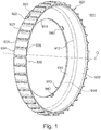
- a diameter reducer 900 implemented on a clutch mechanism 10 according to the first aspect of the invention and an embodiment of which will be described later with reference to the FIGURES 3 to 5 .
- the diameter reducer 900 has a general shape both cylindrical and annular around a longitudinal axis O. It comprises an annular radial elongation bearing 910, that is to say perpendicular to the longitudinal axis O, and a range a cylindrical bearing 930 located at the outer radial end of the annular bearing 910.
- the annular bearing surface 910 is bounded radially inwards by a circular inner contour 911 of axis longitudinal O; and it is bounded radially outwardly by a circular outer contour 912 coaxial with the inner circular contour 911.
- the annular bearing surface 910 is delimited by a first annular face 913 and a second annular face 914, said first and second annular faces 913, 914 being of radial extension and parallel to each other .
- the axial thickness of the annular bearing surface 910 that is to say the distance taken along the longitudinal axis O between the first annular face 913 and the second annular face 914 is small, typically of the order of a few millimeters.
- the diameter of the circular inner contour 911 is substantially smaller than the diameter of the circular outer contour 912, so that a radial distance between said circular inner contour 911 and said circular outer contour 912 is significantly smaller than the axial thickness of the span.
- the axial thickness of the annular bearing surface 910 is about 10 times smaller than the radial distance between said circular inner contour 911 and said circular outer contour 912.
- the cylindrical bearing 930 of the diameter reducer is situated at the upper radial end of the annular bearing surface 910, and it extends axially on one side only with respect to said annular bearing surface 910, so that the annular bearing surface 910 forms a flange. More particularly, the cylindrical surface 930 extends axially between on the one hand a first annular face 934 located in the extension of the first annular face 913 of the annular bearing surface 910, and on the other hand a second annular face 935 located axially at the second face 914 of the ring span 910.
- the cylindrical surface 930 is delimited by a cylindrical inner face 932 and a cylindrical outer face 931 whose diameter is greater than that of the inner cylindrical face 932.
- the radial thickness of the cylindrical surface 930 that is to say the distance taken perpendicular to the longitudinal axis O between the inner cylindrical face 932 and the outer cylindrical face 931, is small, typically of the order of a few millimeters. .
- annular bearing surface 910 and the cylindrical bearing surface 930 of the diameter reducer 900 collectively form a cylindrical sleeve whose first annular face 913 of the annular bearing surface 910 forms a flange for said sleeve.
- the outer face 931 of the cylindrical seat 930 comprises a plurality of ribs 920 forming centering means 920 when the diameter reducer 900 is mounted in the balancing chamber of the clutch mechanism.
- the cylindrical surface 930 is surmounted by a plurality of ribs angularly regularly distributed about the longitudinal axis O.
- Each rib 920 extends axially between the first annular face 934 and the second annular face 935 of the cylindrical bearing surface. Radially, each rib 920 protrudes from the outer face 931 of the cylindrical seat, so that the outer radial end 921 of the ribs 920 is larger in diameter than the outer face 931 of the cylindrical seat 930
- the outer radial ends 921 of all the ribs 920 have the same diameter.
- each rib 920 is delimited by a first lateral face 922 and a second lateral face 923.
- the distance between the first lateral face 922 and the second lateral face 923 is advantageously less than the radial distance between the outer face 931 of the cylindrical seat 930 and the outer radial end 921 of the ribs 920.
- This advantageous configuration allows in particular to make the ribs 920 deformable when a radial force is exerted on the outer radial end 921 of said ribs.
- the diameter reducer 900 is made of plastic, and for example according to a molding process.
- the plastic is advantageously chosen so as to be deformable, that is to say comprising a range of elastic deformation which makes it compatible with the automobile use to which the diameter reducer 900 is intended.
- the diameter of the reducer 900 advantageously comprises fastening means 940 configured to allow to fix it integrally to a part of the clutch mechanism, for example an elastic return device.
- the fastening means 940 are advantageously of the type of riveting or gluing or welding or overmoulding or snapping as shown in FIG. FIGURE 1 .
- the fastening means 940 here take the form of plugs which extend axially from the second face 914 of the annular bearing surface 910 in the direction of the second annular face 935 of the cylindrical bearing surface 930.
- the diameter reducer 900 illustrated on the FIGURE 1 comprises three fixing means 940 which are angularly distributed regularly about the longitudinal axis O.
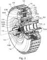
- the clutch mechanism 10 according to the second aspect of the invention is preferably of the double wet clutch type, and preferably still in a so-called radial position, the first clutch 100 being located outside the second clutch 200.
- the double clutch mechanism 10 may be in a so-called axial configuration, the first clutch 100 being located in front of AV the second clutch 200.
- the invention according to its second aspect is not limited to double clutch mechanisms 10 but also includes the mechanisms with simple wet clutch.
- the double clutch mechanism 10 is integrated on a transmission chain 1 comprising a transmission rotatably coupled to the clutch mechanism 100.
- the double-clutch mechanism 10 is arranged to be able to couple in rotation an input shaft not shown to a first transmission shaft A1 or alternatively to a second transmission shaft A2 via the first clutch respectively. 100 or second clutch 200.
- the input shaft is rotated by at least one crankshaft of an engine, for example a heat engine; and the first and second A1 A2 transmission shafts are coaxial and intended to be coupled in rotation to the transmission such as for example a gearbox of the type fitted to motor vehicles.
- an engine for example a heat engine
- the first and second A1 A2 transmission shafts are coaxial and intended to be coupled in rotation to the transmission such as for example a gearbox of the type fitted to motor vehicles.
- each multi-disk clutch comprises on the one hand a plurality of first friction elements 101, 201, such as for example flanges, integrally connected in rotation to the input shaft, and on the other hand a plurality of second friction elements.
- 102, 202 such as for example friction discs, integrally connected in rotation to at least one of the transmission shafts A1, A2.
- the first transmission shaft A1 is rotatably coupled to the input shaft and driven by it in rotation when the first clutch 100 is configured in a so-called engaged position for which the plurality of first friction elements 101 is rotatably coupled to the plurality of second friction elements 102.
- the first transmission shaft A1 is rotatably decoupled from the input shaft when the first clutch 100 is configured in a so-called disengaged position for which the plurality of first friction elements 101 is rotatably decoupled from the plurality of second friction members 102.
- the second transmission shaft A2 is rotatably coupled to the input shaft and rotated by it when the second clutch 200 is configured in an engaged position for which the plurality of first friction elements 201 is coupled. in rotation to the plurality of second friction elements 202.
- the second transmission shaft A2 is rotatably decoupled from the input shaft when the second clutch 200 is configured in a so-called disengaged position for which the plurality of first elements friction member 201 is rotatably decoupled from the plurality of second friction members 202.
- the first clutch 100 and the second clutch 200 are arranged to alternately transmit a so-called input power - a torque and a rotational speed - of the input shaft, to one of the two transmission shafts A1 A2, in according to the respective configuration of each clutch 100 and 200 and via an inlet sail 109.
- the first clutch 100 and the second clutch 200 are arranged not to be simultaneously in the same engaged configuration.
- the first and second clutches 100, 200 can simultaneously be configured in their disengaged position.
- the dual clutch mechanism 10 comprises an input member which is rotatably coupled to the input shaft and the input sail 109 to transmit power - torque and speed. rotation - generated at the motor at one of the clutches 100, 200 of the double clutch mechanism 10.
- the input element of the dual clutch mechanism 10 comprises an inlet hub 130, preferably in rotation around the longitudinal axis O. On its inner elongation, the inlet hub 130 is rotatably and / or axially connected to the input shaft via its internal elongation 1301 damping not shown such as a double damping flywheel for example.
- the inlet hub 130 includes an outer elongation 1302 which is coupled to the entry web 109, and more particularly to an inner end 1091 of the entry web 109.
- the inner end 1091 is located towards the front AV of the web
- the inlet web 109 and the inlet hub 130 are integral, for example fixed by welding and / or riveting.
- the inlet web 109 comprises an upper end 1092 through which the inlet web 109 is rotatably connected to the first clutch 100.
- This connection is made via an outer axial elongation bearing 1061 of a first input disk carrier 106, the first input disk carrier 106 being rotatably connected to the entry web 109, preferably by shape cooperation, for example by splines at the front end AV of said span. of external axial elongation 1061.
- the first clutch 100 and the second clutch 200 are each controlled by an actuating system 300A, 300B which will be described later.
- Each actuating system 300A, 300B is arranged to configure respectively the first clutch 100 and the second clutch 200 in any configuration between the engaged configuration and the disengaged configuration.
- the first actuating system 300A is connected to the first clutch 100 via the first piston 105 comprising a first radially outer portion and a second radially inner portion.
- the first piston 105 is arranged to transmit to the first clutch 100 an axial force E1 exerted parallel to the axis O via its first radially outer part, its second radially inner part collaborating with a force generator to configure the first clutch 100 in one of the previously detailed configurations.
- the first piston 105 comprises a plurality of first axially extending external extension lands 1051 which extend axially forward AV to be able to press the first friction elements 101 against the second friction members.
- first friction elements 101 are spaced apart from the second friction elements 102, then the first clutch 100 is configured in its disengaged configuration.
- first friction members 101 are pressed against the second friction members 102, then the first clutch 100 is configured in its engaged configuration.
- the first piston 105 takes the form of a corrugated sheet and curved axially forward AV at its outer radial end.
- the first piston 105 comprises an upper radially extending extension 1052 rearward AR of the first axial extension spans 1051.
- the first upper radial extension span 1052 extends radially parallel to the transverse axis T from the first clutch. 100 to the inner limit of the second clutch 200.
- the intermediate axial extension range 1053 is located radially under the second clutch 200 and axially rearward AR.
- first piston 105 comprises a first inner radial extension surface 1055 and connected to the intermediate axial extension span 1053 via a first curved zone 1054.
- the inner radial end of the extension reach radial inner 1055 is located at a distance from a support hub 500 which will be described later.
- the first piston 105 can be obtained by stamping.
- the external reaction means 103 is integral with the inlet web 109.
- the external reaction means 103 is connected to the inlet web 109 via the inlet disk carrier 106.
- the external reaction means 103 has a shape complementary to that of the first or second friction elements 101, 102, so as to allow a frictional coupling of the first and second friction elements 101, 102 when the first actuating system 300A exerts the first axial force E1 forward AV to configure the first clutch 100 in its engaged position.
- the first piston 105 is pushed rearward AR by elastic return elements which will be described later, then the first friction elements 101 of the first clutch 100 separate from the second friction elements 102, to decouple said friction elements and thus to configure the first clutch 100 in its disengaged configuration.
- the first clutch 100 is adapted to be rotatably coupled to the first transmission shaft A1 via a first output disk carrier 110 forming an output member of said first clutch 100. More particularly, the first disk carrier of outlet 110 is rotatably coupled to the second friction members 102 through an upper end 1101 that the output disk carrier 110 comprises. More particularly, the first output disk carrier 110 is rotatably coupled to a first output hub 120 through an inner end 1102 that the first output disk carrier 110 comprises.
- the first output disk carrier 110 has on its outer radial periphery an axial elongation 107 which is provided with a toothing intended to cooperate with a complementary toothing on each second friction element 102, and more particularly to the inner radial periphery of each second friction element 102 of the first clutch 100.
- the axial elongation 107 of the first output disk carrier 110 is located radially under the first 101 and second 102 friction elements of the first clutch 100.
- the first output disk carrier 110 is thus coupled in rotation by meshing with the second friction elements 102 of the first clutch 100.
- the first output hub 120 has radially inside axial splines arranged to cooperate with complementary splines located on the first transmission shaft A1 so as to achieve a rotational coupling.
- a radial bearing 117 is interposed between the first output hub 120 and the inlet hub 130 to withstand the radial forces of the inlet hub 130 and / or the inlet web 109 despite the different speeds of rotation respectively turn the input shaft and the first drive shaft A1.
- the second clutch 200 of the dual clutch mechanism 10 is similar in design to that of the first clutch 100.
- the second actuating system 300B is connected to the second clutch 200 via a second piston 205.
- the second piston 205 is located axially between a second output disk carrier 206 and the second clutch 200.
- the second actuating system 300B is connected to the second clutch 200 via the second piston 205 comprising a first radially outer portion and a second radially inner portion.
- the second piston 205 is arranged to transmit to the second clutch 200 an axial force E2 exerted parallel to the longitudinal axis O via its first radially outer part collaborating with the friction elements 201, 202 of said second clutch 200, and its second radially inner portion collaborating with a force generator to configure the second clutch 200 in one of the previously detailed configurations.
- the second piston 205 comprises a plurality of second axial extension lands 2051 that extend axially forward AV to press the first friction members 201 against the second friction members 202.
- the second piston 205 takes the form of a corrugated sheet and curved axially forward AV at its outer radial end.
- the second piston 205 comprises an upper radial extension surface 2052 located rearwardly of the second axial extension surfaces 2051.
- the upper radial extension surface 2052 of the second piston 205 is interposed axially between a second inlet disk carrier. 206 and the second clutch 200.
- the upper radial extension range 2052 extends radially from the second clutch 200 to the inside of the second clutch 200, and more particularly outside a range of axial extension. intermediate 2063 of the second output disk carrier 206.
- An intermediate axial extension surface 2053 of the second piston 205 extends forward AV and parallel to the axis O the upper radial extension range 2052 of the second piston 205.
- the intermediate axial extension range 2053 is located radially at inside the second clutch 200 and outside the intermediate axial extension span 2063 of the second output disk carrier 206.
- the second piston 205 includes a plurality of second inner radial extension lands 2055 and connected to the intermediate axial reach 2053 through a curved zone 2054 of the second piston 205.
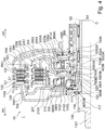
- the curved zone 2054 of the second piston 205 takes the form of an "S" in the transverse sectional plane shown in FIG. FIGURE 4 .
- the second piston 205 can be obtained by stamping.
- the second output disk carrier 206 of the dual clutch mechanism 10 comprises an outer axial extension portion 2061 facing forward AV.
- the outer axial elongation portion 2061 of the second output disk carrier 206 is located radially outwardly of the second clutch 200, and extends axially along the entire length of said second clutch 200.
- the second output disk carrier 206 also includes an upper radial extension area 2062 rearward AR of the portion The upper radial extension span 2062 extends radially from the outside of the second clutch 200 to the inside of the second clutch 200.
- An intermediate axial extension surface 2063 of the second output disk carrier 206 extends forward AV and parallel to the axis O the upper radial extension range 2062 of the second output disk carrier 206.
- the range of intermediate axial extension 2063 is located radially under the second axial bearing surface 2053 of the second piston 205.
- the second output disk carrier 206 includes an inner radial extension span 2065 connected to the intermediate axial extension span 2063 via a curved zone 2064.
- the inner radial end of the radial reach Inner radial extension 2065 is fixed integrally against the support hub 500, for example by welding.
- each output disk carrier 106, 206 is respectively fixedly secured to said support hub 500 by through its inner radial end.
- the internal reaction means 203 is integral with the second input disk carrier 206, and more particularly at its outer axial extension portion 2061 to which the internal reaction means 203 is fixed by any means, such as for example by welding or riveting.
- the inner reaction means 203 and the second input disk carrier 206 are made of material.
- the external reaction means 203 has a shape complementary to that of the first or second friction elements 201, 202, so as to allow a friction coupling of the first and second friction elements 201, 202 when the second actuating system 300B exerts an axial forward force E2 AV to configure the second clutch 200 in its engaged position.
- the second clutch 200 is intended to be rotatably coupled to the second transmission shaft A2 via a second output disk carrier 210 forming an output element of said second clutch 200. More particularly, the second disk carrier of output 210 is rotatably coupled to the second friction members 202 through an upper end 2101 that the second output disk carrier 210 comprises. The second output disk carrier 210 is rotatably coupled to a second output hub 220 through an inner end 2102, which the second output disk carrier 210 comprises.
- the second output disk carrier 210 comprises on its outer radial periphery an axial elongation 207 which is provided with a toothing intended to cooperate with a complementary toothing on each second friction element 202, and more particularly to the inner radial periphery of each second friction element 202 of the second clutch 200.
- the second output disk carrier 210 is thus coupled in rotation by meshing with the second friction elements 202 of the second clutch 200.
- the second output hub 220 has at its inner end 2102 axial splines arranged to cooperate with complementary splines located on the second transmission shaft A2, so as to achieve a rotational coupling.
- an axial bearing 116 is interposed between the first output disk carrier 110 and the second output disk carrier 210 in order to be able to transmit an axial force between the two output disk carriers 110, 210 which can rotate at different speeds. different speeds when the first and second clutches 100, 200 are configured in a different configuration.
- each actuating system 300A, 300B further comprises an elastic return device 800A, 800B arranged to generate an axial force directed towards the rear AR and opposing the displacement of the corresponding piston 105, 205 when it is pushed towards the front AV to engage the clutch 100, 200 corresponding.
- the control chamber 750A of the first actuating system 300A is arranged to receive a certain volume of hydraulic fluid under pressure in order to generate the axial force E1 on the inner radial extension range 1055 of the first piston 105 and thus to configure the first clutch 100 in one of the configurations described above.
- the pressurized hydraulic fluid is advantageously conveyed via high pressure fluidic circulation ducts at least partly passing through the support hub 500 and opening into the control chamber 750A of the first actuating system 300A at an outer face of said support hub 500 by a supply duct 5002A.
- the balancing chamber 700A of the first actuating system 300A is arranged to receive a certain volume of hydraulic fluid for lubricating the first elastic return device 800A housed in said balancing chamber 700A.
- the lubricating fluid is advantageously conveyed via low pressure fluidic circulation ducts passing axially through the support hub 500 and opening into the balancing chamber 700A at an outer face of said support hub 500 via a supply duct. 5003A.
- control chamber 750B of the second actuating system 300B is arranged to receive a certain volume of hydraulic fluid under pressure in order to generate the axial force E2 on the inner radial extension surface 2055 of the second piston 205 and thus to configure the second clutch 200 in one of the previously described configurations.
- the pressurized hydraulic fluid is advantageously conveyed via high pressure fluidic circulation ducts passing through at least part of the support hub 500 and opening into the control chamber 750B of the second actuating system 300B at an outer face of said support hub 500 by a supply duct 5002B.
- the balancing chamber 700B of the second actuating system 300B is arranged to receive a certain volume of hydraulic fluid for lubricating the second elastic return device 800B housed in said balancing chamber 700B.
- the lubricating fluid is advantageously conveyed via low pressure fluidic circulation conduits passing axially through the support hub 500 and opening into the balancing chamber 700B of the second actuating system 300B at an outer face of said support hub 500 by a supply conduit 5003B.
- the low pressure fluidic circulation ducts comprise a main supply duct 5001 located at the axial front end AV of the support hub 500.
- the main supply duct is of radial orientation and makes it possible to establish a communication fluidic fluid lubricant directly above the clutches 100, 200 to improve their lubrication during operation of the dual clutch mechanism 10 according to the second aspect of the invention.
- the actuating systems 300A, 300B thus form force generators for the force transmission members 105, 205 of the corresponding clutches 100, 200.
- each actuating system 300 comprises a diameter reducer 900 housed in the balancing chamber 700 in order to re-define said balancing chamber, and more particularly to adapt the outside diameter of the balancing chamber to to match the outside diameter of the control chamber 750.
- the annular bearing surface 910 of the diameter reducer 900 associated with the balancing chamber 700A of the first actuating system is inserted axially between the first annular piece 810A of the first elastic return device 300A and the radial extension range. 2065 of the second inlet disk carrier 206.
- the outer radial end 921 of the ribs 920 located on the cylindrical outer face 931 of the cylindrical surface 930 of the diameter reducer 900 is in radial abutment against the extension scope intermediate axial 2063 of the second output disk carrier 206, to perform a centering of the diameter reducer.
- the cylindrical inner face 932 of the diameter reducer 900 is located on a smaller diameter or - preferably - equal to the diameter of an inner face of the intermediate radial extension surface 1053 of the first piston 105 delimiting radially outwardly the first control room 750A.
- the diameter of the cylindrical inner face 932 of the diameter reducer 900 is greater than 98% and less than 102% of the diameter of the inner face of the intermediate radial extension surface 1053 of the first piston 105 delimiting radially towards outside the first control room 750A.
- control chamber 750A and the balancing chamber 700A of the first control system 300A have the same outside diameter, thereby limiting the differential effects of centrifugation of the lubricating fluid filling the balancing chamber 700A and pressurized fluid filling the control room 750A.
- the annular bearing surface 910B of the diameter reducer 900B associated with the balancing chamber 700B of the second actuating system 300B is inserted axially between the first annular part 810B of the second elastic return device 300B and an extension seat radial 3321 of the lining plate 332.
- the outer radial end 921B of the ribs 920B located on the cylindrical outer face 931B of the cylindrical surface 930B of the diameter reducer 900B is in radial abutment against an axial extension range 3322 of the lining plate 332, in order to achieve a centering of the diameter reducer.
- the cylindrical inner face 932 of the diameter reducer 900B is located on a smaller diameter or - preferably - equal to the diameter of an inner face of the intermediate radial extension surface 2053 of the second piston 205 delimiting radially outwardly the second control room 750B.
- the diameter of the cylindrical inner face 932 of the diameter reducer 900 is greater than 98% and less than 102% of the diameter of the inner face of the intermediate radial extension surface 2053 of the second piston 205 delimiting radially towards outside the second control room 750B.
- control chamber 750B and the balancing chamber 700B of the second control system 300B have the same external diameter, thus making it possible to limit the differential effects of centrifugation of the lubricating fluid. filling the balancing chamber 700B and pressurized fluid filling the control room 750B.
- the third seal 403 of each actuating system 300 is in radial abutment against the inner cylindrical face 932 of the corresponding diameter reducer 900, and more particularly by means of a lip located at one end of said third seal sealing.
- the third seal 403 slides along the face internal 932 cylindrical reducer diameter 900 corresponding to maintain the tightness of the balancing chamber 700 and limit or prevent leakage of the lubricating fluid from the balancing chamber 700.
- the state of surface of the inner face 932 cylindrical diameter reducer 900 is advantageously particularly smooth, with a suitable roughness.
- the roughness is between the two following extremes: a maximum limit of roughness making it possible not to wear the third seal 403 when it slides along the inner cylindrical face 932 of the corresponding diameter reducer 900, and a minimum roughness limit to (i) ensure contact between the third seal 403 and the diameter reducer 900 and (ii ) to prevent the occurrence of a hydraulic fluid leak due to a roughness too low.
- the extreme roughness values may depend on the material used.
- the diameter reducer 900 also comprises fastening means 940, 950 of said diameter reducer 900 to the elastic return device 800 and / or to a side face of the balancing chamber 700.
- the diameter reducer 900 comprises first fixing means 940 arranged to allow the assembly of the diameter reducer 900 on the elastic return device 800, preferably of the type of a riveting or snapping or gluing or welding or overmolding.
- the diameter reducer 900 also comprises second fixing means 950 arranged to allow the assembly of the diameter reducer 900 on the side face of the balancing chamber 700, preferably of the type of a riveting.
- the first fixing means 940 diameter reducer 900 are common with the second fastening means 950 of said diameter reducer 900.
- the first annular piece 810 of the elastic return device 800 and the annular bearing 910 of the diameter reducer 900 and the lateral face of the balancing chamber 700 are simultaneously fixed to each other by means of a fastening means 940, 950, which here takes the form of a rivet passing through said first annular piece 810 and said span. annular 910 and said side face.
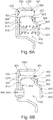
- FIGURE 7 an embodiment of an elastic return device 800 according to the first aspect of the invention is shown.
- the second annular piece 820 of the elastic return device 800 has an axis of symmetry S.
- the second annular piece 820A is formed by a radial elongation edge 821A extending from the inner radial end 8211A to an oblique intermediate bearing 822A.
- the oblique intermediate land 822A is extended radially outwardly by an outer radial extension bearing 823A which carries at its outer end 8231A a seal 403A, said third seal 403A.
- the inner radial end 8211A of the second annular piece 820A of the elastic return device 800 is located in the radial extension of the radial elongation edge 821A of said second annular piece 820A.
- the second annular piece 820A also comprises a plurality of openings 840A regularly angularly distributed around the axis of symmetry S.
- the openings 860A form holes opening through the second annular piece 820A.
- the openings 860A are intended to allow fluid communication between on the one hand a first side of the second annular part 820A located between said second annular part 820A and the first annular part 810 and secondly on a second side of the second annular part. 820A located opposite the first side relative to said second annular piece 820A.
- the elastic return device 800 advantageously comprises the diameter reducer 900 according to the first aspect of the invention and as described above.
- the cylindrical surface 930 of the diameter reducer 900 is in radial contact with a bearing part of the clutch mechanism, for example a second outlet disk carrier 206 as shown in FIG. FIGURE 7 .
- the ribs 920A of the diameter reducer are in radial abutment against an inner face of the intermediate axial extension surface 2063 of the second input disk carrier 206, as described above.
- the annular bearing 910 of the diameter reducer 900 is advantageously interposed between the first annular part 810A and the bearing part of the clutch mechanism. More particularly, the annular bearing surface 910 of the diameter reducer 900 bears axially against the first annular part 810A of the elastic return device 800.
- An upper radial end of the third seal 403A is in abutment against the diameter reducer 900. More particularly, the third seal 403A comprises a lip which is in radial abutment against the inner face 932 cylindrical of the cylindrical seat 930 diameter reducer 900.
- the elastic return device 800 also comprises fastening means 850A collaborating with complementary fastening means 940 of the diameter reducer 900 for fastening said diameter reducer 900 to the first annular piece 810A of the elastic return device. 800.
- the fixing means 850A are of the type of at least one rivet angularly regularly distributed around the axis of symmetry S.
- the support part of the clutch mechanism comprises an opening 2069 located opposite the fixing means 850 of the elastic return device 800.
Applications Claiming Priority (1)
| Application Number | Priority Date | Filing Date | Title |
|---|---|---|---|
| FR1751606A FR3063321B1 (fr) | 2017-02-28 | 2017-02-28 | Mecanisme d'embrayage humide dont la lubrification est amelioree |
Publications (1)
| Publication Number | Publication Date |
|---|---|
| EP3366941A1 true EP3366941A1 (de) | 2018-08-29 |
Family
ID=58645258
Family Applications (1)
| Application Number | Title | Priority Date | Filing Date |
|---|---|---|---|
| EP18158270.1A Withdrawn EP3366941A1 (de) | 2017-02-28 | 2018-02-23 | Nasskupplungsmechanismus mit verbesserter schmierung |
Country Status (3)
| Country | Link |
|---|---|
| EP (1) | EP3366941A1 (de) |
| CN (1) | CN108506362A (de) |
| FR (1) | FR3063321B1 (de) |
Cited By (5)
| Publication number | Priority date | Publication date | Assignee | Title |
|---|---|---|---|---|
| FR3095021A1 (fr) * | 2019-04-09 | 2020-10-16 | Valeo Embrayages | Mecanisme d’embrayage humide comprenant une etancheite amelioree |
| CN113062932A (zh) * | 2020-01-02 | 2021-07-02 | 广州汽车集团股份有限公司 | 一种湿式双离合器总成的油路系统 |
| CN113661338A (zh) * | 2019-05-14 | 2021-11-16 | 舍弗勒技术股份两合公司 | 用于机动车的离合器设备、混动模块以及驱动装置 |
| DE102021207080A1 (de) | 2021-03-29 | 2022-09-29 | Magna Pt B.V. & Co. Kg | Mehrfachlamellenkupplungsanordnung mit Kolben |
| EP4239209A1 (de) * | 2022-03-01 | 2023-09-06 | Valeo Embrayages | Kupplungsmodul und verfahren zum schliessen eines solchen kupplungsmoduls |
Families Citing this family (3)
| Publication number | Priority date | Publication date | Assignee | Title |
|---|---|---|---|---|
| DE102019118699A1 (de) * | 2019-07-10 | 2021-01-14 | Schaeffler Technologies AG & Co. KG | Betätigungsvorrichtung für eine Lamellenbremse sowie Getriebeanordnung mit der Betätigungsvorrichtung und der Lamellenbremse |
| FR3102815B1 (fr) * | 2019-10-31 | 2021-10-15 | Valeo Embrayages | Mecanisme d’embrayage multidisques comprenant une etancheite amelioree |
| US11512747B2 (en) | 2020-01-09 | 2022-11-29 | Cnh Industrial America Llc | Balanced piston clutch |
Citations (7)
| Publication number | Priority date | Publication date | Assignee | Title |
|---|---|---|---|---|
| DE20310015U1 (de) * | 2003-06-18 | 2003-08-28 | Zf Sachs Ag | Kupplungseinrichtung, insbesondere Doppel- oder Mehrfachkupplungseinrichtung, und Dichtungskonzept hierfür |
| DE102007027122A1 (de) * | 2007-06-13 | 2008-12-18 | Volkswagen Ag | Kupplungshauptnabe bzw. Doppelkupplung mit einer derartigen Kupplungshauptnabe |
| DE102011006027A1 (de) * | 2011-03-24 | 2012-09-27 | Zf Friedrichshafen Ag | Ölzuführnabe für eine nasslaufende Doppelkupplung |
| DE102012218829A1 (de) * | 2011-12-15 | 2013-06-20 | Schaeffler Technologies AG & Co. KG | Doppelkupplung und Verfahren zu deren Montage |
| DE102012221958A1 (de) * | 2011-12-15 | 2013-06-20 | Schaeffler Technologies AG & Co. KG | Doppelkupplung |
| DE102012023721A1 (de) * | 2012-12-05 | 2014-06-05 | Borg Warner Inc. | Torsionsschwingungsdämpfer mit Kupplungseinrichtung und Antriebsstrang für ein Kraftfahrzeug mit einem solchen Torsionsschwingungsdämpfer |
| DE102014212701A1 (de) * | 2014-07-01 | 2016-01-07 | Dichtungstechnik G. Bruss Gmbh & Co. Kg | Vorrichtung zur Betätigung einer Kupplung in einem hydraulischen System und Verfahren zur Herstellung einer solchen Vorrichtung |
-
2017
- 2017-02-28 FR FR1751606A patent/FR3063321B1/fr active Active
-
2018
- 2018-02-23 EP EP18158270.1A patent/EP3366941A1/de not_active Withdrawn
- 2018-02-27 CN CN201810163677.5A patent/CN108506362A/zh active Pending
Patent Citations (7)
| Publication number | Priority date | Publication date | Assignee | Title |
|---|---|---|---|---|
| DE20310015U1 (de) * | 2003-06-18 | 2003-08-28 | Zf Sachs Ag | Kupplungseinrichtung, insbesondere Doppel- oder Mehrfachkupplungseinrichtung, und Dichtungskonzept hierfür |
| DE102007027122A1 (de) * | 2007-06-13 | 2008-12-18 | Volkswagen Ag | Kupplungshauptnabe bzw. Doppelkupplung mit einer derartigen Kupplungshauptnabe |
| DE102011006027A1 (de) * | 2011-03-24 | 2012-09-27 | Zf Friedrichshafen Ag | Ölzuführnabe für eine nasslaufende Doppelkupplung |
| DE102012218829A1 (de) * | 2011-12-15 | 2013-06-20 | Schaeffler Technologies AG & Co. KG | Doppelkupplung und Verfahren zu deren Montage |
| DE102012221958A1 (de) * | 2011-12-15 | 2013-06-20 | Schaeffler Technologies AG & Co. KG | Doppelkupplung |
| DE102012023721A1 (de) * | 2012-12-05 | 2014-06-05 | Borg Warner Inc. | Torsionsschwingungsdämpfer mit Kupplungseinrichtung und Antriebsstrang für ein Kraftfahrzeug mit einem solchen Torsionsschwingungsdämpfer |
| DE102014212701A1 (de) * | 2014-07-01 | 2016-01-07 | Dichtungstechnik G. Bruss Gmbh & Co. Kg | Vorrichtung zur Betätigung einer Kupplung in einem hydraulischen System und Verfahren zur Herstellung einer solchen Vorrichtung |
Cited By (7)
| Publication number | Priority date | Publication date | Assignee | Title |
|---|---|---|---|---|
| FR3095021A1 (fr) * | 2019-04-09 | 2020-10-16 | Valeo Embrayages | Mecanisme d’embrayage humide comprenant une etancheite amelioree |
| CN113661338A (zh) * | 2019-05-14 | 2021-11-16 | 舍弗勒技术股份两合公司 | 用于机动车的离合器设备、混动模块以及驱动装置 |
| CN113062932A (zh) * | 2020-01-02 | 2021-07-02 | 广州汽车集团股份有限公司 | 一种湿式双离合器总成的油路系统 |
| CN113062932B (zh) * | 2020-01-02 | 2023-08-15 | 广州汽车集团股份有限公司 | 一种湿式双离合器总成的油路系统 |
| DE102021207080A1 (de) | 2021-03-29 | 2022-09-29 | Magna Pt B.V. & Co. Kg | Mehrfachlamellenkupplungsanordnung mit Kolben |
| EP4239209A1 (de) * | 2022-03-01 | 2023-09-06 | Valeo Embrayages | Kupplungsmodul und verfahren zum schliessen eines solchen kupplungsmoduls |
| FR3133222A1 (fr) * | 2022-03-01 | 2023-09-08 | Valeo Embrayages | Module d’embrayage et procede de fermeture d’un tel module d’embrayage |
Also Published As
| Publication number | Publication date |
|---|---|
| FR3063321B1 (fr) | 2019-11-22 |
| CN108506362A (zh) | 2018-09-07 |
| FR3063321A1 (fr) | 2018-08-31 |
Similar Documents
| Publication | Publication Date | Title |
|---|---|---|
| FR3063321B1 (fr) | Mecanisme d'embrayage humide dont la lubrification est amelioree | |
| EP3366938B1 (de) | Elastische rückholvorrichtung für nasskupplungsmechanismus, und nasskupplung, die eine solche elastische rückholvorrichtung umfasst | |
| EP3252333B1 (de) | Axiales einrastsystem für einen kupplungsmechanismus | |
| EP3364063B1 (de) | Kompakter doppelkupplungsmechanismus, und übertragungssystem, das einen solchen doppelkupplungsmechanismus umfasst | |
| EP3580468B1 (de) | Lösbarer doppelkupplungsmechanismus | |
| EP3494323B1 (de) | Kompakter doppelkupplungsmechanismus und getriebesystem mit solch einem doppelkupplungsmechanismus | |
| FR3049024A1 (fr) | Double embrayage humide avec butees de securite aptes a limiter la course des pistons du systeme de commande | |
| FR3054865A1 (fr) | Mecanisme d'embrayage et systeme de transmission comprenant un tel mecanisme d'embrayage | |
| FR3062694A1 (fr) | Mecanisme a double embrayage compact et systeme de transmission comprenant un tel mecanisme a double embrayage | |
| WO2019228892A1 (fr) | Porte-disque assemble et mecanisme d'embrayage humide comprenant ce porte-disque assemble | |
| WO2018096114A1 (fr) | Assemblage radial d'un mecanisme d'embrayage sur une transmission | |
| FR3067076A1 (fr) | Mecanisme d'embrayage comprenant deux ensembles separes par un dispositif de reglage d'une distance axiale | |
| FR3079573A1 (fr) | Porte-disques pour mecanisme d'embrayage de vehicule automobile et module d'embrayage comprenant un tel porte-disques | |
| FR3054867A1 (fr) | Mecanisme a double embrayage et systeme de transmission comprenant un tel mecanisme a double embrayage | |
| EP3635271B1 (de) | Kupplungsmechanismus mit zwei durch eine montagevorrichtung verbundenen anordnungen | |
| FR3053091A1 (fr) | Embrayage hydrocinetique pour un vehicule automobile | |
| FR3066570A1 (fr) | Porte-disques d'entree d'un mecanisme a double embrayages et mecanisme a double embrayages | |
| EP3810947B1 (de) | Schmierungsring und kupplungsmodul mit einem solchen schmierungsring | |
| FR3051863B1 (fr) | Mecanisme d'embrayage compact comportant des paliers radiaux distincts des paliers axiaux | |
| WO2019008292A2 (fr) | Porte-disque de sortie d'un double embrayages et mecanisme comprenant un tel porte-disque | |
| FR3102815A1 (fr) | Mecanisme d’embrayage multidisques comprenant une etancheite amelioree | |
| FR3083278A1 (fr) | Porte-disque assemble et mecanisme d'embrayage humide comprenant ce porte-disque assemble | |
| WO2018086905A1 (fr) | Mecanisme a double embrayage compact et systeme de transmission comprenant un tel mecanisme a double embrayage | |
| FR3085731A1 (fr) | Mecanisme a double embrayage | |
| FR3083277A1 (fr) | Porte-disque assemble et mecanisme d'embrayage humide comprenant ce porte-disque assemble |
Legal Events
| Date | Code | Title | Description |
|---|---|---|---|
| STAA | Information on the status of an ep patent application or granted ep patent |
Free format text: STATUS: EXAMINATION IS IN PROGRESS |
|
| PUAI | Public reference made under article 153(3) epc to a published international application that has entered the european phase |
Free format text: ORIGINAL CODE: 0009012 |
|
| 17P | Request for examination filed |
Effective date: 20180223 |
|
| AK | Designated contracting states |
Kind code of ref document: A1 Designated state(s): AL AT BE BG CH CY CZ DE DK EE ES FI FR GB GR HR HU IE IS IT LI LT LU LV MC MK MT NL NO PL PT RO RS SE SI SK SM TR |
|
| AX | Request for extension of the european patent |
Extension state: BA ME |
|
| STAA | Information on the status of an ep patent application or granted ep patent |
Free format text: STATUS: EXAMINATION IS IN PROGRESS |
|
| STAA | Information on the status of an ep patent application or granted ep patent |
Free format text: STATUS: THE APPLICATION IS DEEMED TO BE WITHDRAWN |
|
| 18D | Application deemed to be withdrawn |
Effective date: 20210330 |