EP3366262A1 - Dispositifs médicaux gonflables renforcés - Google Patents
Dispositifs médicaux gonflables renforcés Download PDFInfo
- Publication number
- EP3366262A1 EP3366262A1 EP18167468.0A EP18167468A EP3366262A1 EP 3366262 A1 EP3366262 A1 EP 3366262A1 EP 18167468 A EP18167468 A EP 18167468A EP 3366262 A1 EP3366262 A1 EP 3366262A1
- Authority
- EP
- European Patent Office
- Prior art keywords
- shell
- balloon
- narrowly
- section
- fiber
- Prior art date
- Legal status (The legal status is an assumption and is not a legal conclusion. Google has not performed a legal analysis and makes no representation as to the accuracy of the status listed.)
- Granted
Links
- 230000002787 reinforcement Effects 0.000 claims description 128
- 239000012530 fluid Substances 0.000 claims description 76
- 239000000853 adhesive Substances 0.000 claims description 71
- 230000001070 adhesive effect Effects 0.000 claims description 71
- 238000004891 communication Methods 0.000 claims description 15
- 239000000835 fiber Substances 0.000 description 234
- 239000010410 layer Substances 0.000 description 119
- 238000000034 method Methods 0.000 description 92
- 239000002775 capsule Substances 0.000 description 38
- 210000001765 aortic valve Anatomy 0.000 description 32
- 239000000463 material Substances 0.000 description 31
- 239000011248 coating agent Substances 0.000 description 30
- 238000000576 coating method Methods 0.000 description 30
- 239000003550 marker Substances 0.000 description 28
- 239000011159 matrix material Substances 0.000 description 27
- 239000011295 pitch Substances 0.000 description 25
- 239000010408 film Substances 0.000 description 20
- 239000002904 solvent Substances 0.000 description 19
- 229910045601 alloy Inorganic materials 0.000 description 17
- 239000000956 alloy Substances 0.000 description 17
- 238000004519 manufacturing process Methods 0.000 description 16
- -1 EPTFE Polymers 0.000 description 13
- 230000006835 compression Effects 0.000 description 11
- 238000007906 compression Methods 0.000 description 11
- 238000003780 insertion Methods 0.000 description 11
- 230000037431 insertion Effects 0.000 description 11
- 210000005166 vasculature Anatomy 0.000 description 11
- 229920000642 polymer Polymers 0.000 description 10
- 229920006254 polymer film Polymers 0.000 description 10
- 210000004369 blood Anatomy 0.000 description 9
- 239000008280 blood Substances 0.000 description 9
- 239000007788 liquid Substances 0.000 description 9
- 229920001169 thermoplastic Polymers 0.000 description 9
- 239000004416 thermosoftening plastic Substances 0.000 description 9
- XLYOFNOQVPJJNP-UHFFFAOYSA-N water Substances O XLYOFNOQVPJJNP-UHFFFAOYSA-N 0.000 description 9
- 230000008859 change Effects 0.000 description 8
- 239000003814 drug Substances 0.000 description 8
- 229940079593 drug Drugs 0.000 description 8
- 229920000052 poly(p-xylylene) Polymers 0.000 description 8
- 210000000709 aorta Anatomy 0.000 description 7
- ZWEHNKRNPOVVGH-UHFFFAOYSA-N 2-Butanone Chemical compound CCC(C)=O ZWEHNKRNPOVVGH-UHFFFAOYSA-N 0.000 description 6
- 239000004677 Nylon Substances 0.000 description 6
- 238000013158 balloon valvuloplasty Methods 0.000 description 6
- 210000003709 heart valve Anatomy 0.000 description 6
- 238000010438 heat treatment Methods 0.000 description 6
- 229920001778 nylon Polymers 0.000 description 6
- 230000010412 perfusion Effects 0.000 description 6
- 230000002792 vascular Effects 0.000 description 6
- 239000012298 atmosphere Substances 0.000 description 5
- 238000005520 cutting process Methods 0.000 description 5
- 238000002513 implantation Methods 0.000 description 5
- 210000005240 left ventricle Anatomy 0.000 description 5
- 229910052751 metal Inorganic materials 0.000 description 5
- 239000002184 metal Substances 0.000 description 5
- 230000036961 partial effect Effects 0.000 description 5
- 239000005020 polyethylene terephthalate Substances 0.000 description 5
- 239000010409 thin film Substances 0.000 description 5
- 238000012800 visualization Methods 0.000 description 5
- 229920002799 BoPET Polymers 0.000 description 4
- 239000004696 Poly ether ether ketone Substances 0.000 description 4
- 229920002614 Polyether block amide Polymers 0.000 description 4
- WYURNTSHIVDZCO-UHFFFAOYSA-N Tetrahydrofuran Chemical compound C1CCOC1 WYURNTSHIVDZCO-UHFFFAOYSA-N 0.000 description 4
- 230000010339 dilation Effects 0.000 description 4
- 238000011068 loading method Methods 0.000 description 4
- 238000002844 melting Methods 0.000 description 4
- 230000008018 melting Effects 0.000 description 4
- 229920000728 polyester Polymers 0.000 description 4
- 229920002530 polyetherether ketone Polymers 0.000 description 4
- 229920000139 polyethylene terephthalate Polymers 0.000 description 4
- 229920002635 polyurethane Polymers 0.000 description 4
- 239000004814 polyurethane Substances 0.000 description 4
- 229920002451 polyvinyl alcohol Polymers 0.000 description 4
- 239000011148 porous material Substances 0.000 description 4
- 238000003825 pressing Methods 0.000 description 4
- 230000002829 reductive effect Effects 0.000 description 4
- 238000000926 separation method Methods 0.000 description 4
- 239000012453 solvate Substances 0.000 description 4
- 229920001187 thermosetting polymer Polymers 0.000 description 4
- JOYRKODLDBILNP-UHFFFAOYSA-N Ethyl urethane Chemical compound CCOC(N)=O JOYRKODLDBILNP-UHFFFAOYSA-N 0.000 description 3
- 239000004812 Fluorinated ethylene propylene Substances 0.000 description 3
- VVQNEPGJFQJSBK-UHFFFAOYSA-N Methyl methacrylate Chemical compound COC(=O)C(C)=C VVQNEPGJFQJSBK-UHFFFAOYSA-N 0.000 description 3
- 239000005041 Mylar™ Substances 0.000 description 3
- 239000004372 Polyvinyl alcohol Substances 0.000 description 3
- FAPWRFPIFSIZLT-UHFFFAOYSA-M Sodium chloride Chemical compound [Na+].[Cl-] FAPWRFPIFSIZLT-UHFFFAOYSA-M 0.000 description 3
- 210000003484 anatomy Anatomy 0.000 description 3
- 238000005452 bending Methods 0.000 description 3
- 230000006378 damage Effects 0.000 description 3
- 229920001971 elastomer Polymers 0.000 description 3
- 239000000806 elastomer Substances 0.000 description 3
- 229920002313 fluoropolymer Polymers 0.000 description 3
- 239000004811 fluoropolymer Substances 0.000 description 3
- 239000011888 foil Substances 0.000 description 3
- 230000006870 function Effects 0.000 description 3
- 239000007943 implant Substances 0.000 description 3
- 238000012856 packing Methods 0.000 description 3
- 229920009441 perflouroethylene propylene Polymers 0.000 description 3
- 229920001296 polysiloxane Polymers 0.000 description 3
- 235000019422 polyvinyl alcohol Nutrition 0.000 description 3
- 230000008569 process Effects 0.000 description 3
- 239000002356 single layer Substances 0.000 description 3
- 230000007704 transition Effects 0.000 description 3
- 238000009966 trimming Methods 0.000 description 3
- 238000004804 winding Methods 0.000 description 3
- VSSAADCISISCOY-UHFFFAOYSA-N 1-(4-furo[3,4-c]pyridin-1-ylphenyl)furo[3,4-c]pyridine Chemical compound C1=CN=CC2=COC(C=3C=CC(=CC=3)C3=C4C=CN=CC4=CO3)=C21 VSSAADCISISCOY-UHFFFAOYSA-N 0.000 description 2
- LFQSCWFLJHTTHZ-UHFFFAOYSA-N Ethanol Chemical compound CCO LFQSCWFLJHTTHZ-UHFFFAOYSA-N 0.000 description 2
- VGGSQFUCUMXWEO-UHFFFAOYSA-N Ethene Chemical compound C=C VGGSQFUCUMXWEO-UHFFFAOYSA-N 0.000 description 2
- PXHVJJICTQNCMI-UHFFFAOYSA-N Nickel Chemical compound [Ni] PXHVJJICTQNCMI-UHFFFAOYSA-N 0.000 description 2
- 208000031481 Pathologic Constriction Diseases 0.000 description 2
- 239000004952 Polyamide Substances 0.000 description 2
- 229920006373 Solef Polymers 0.000 description 2
- 239000004433 Thermoplastic polyurethane Substances 0.000 description 2
- 239000000654 additive Substances 0.000 description 2
- 230000000996 additive effect Effects 0.000 description 2
- 239000012790 adhesive layer Substances 0.000 description 2
- 238000002399 angioplasty Methods 0.000 description 2
- 238000010009 beating Methods 0.000 description 2
- 229910052797 bismuth Inorganic materials 0.000 description 2
- JCXGWMGPZLAOME-UHFFFAOYSA-N bismuth atom Chemical compound [Bi] JCXGWMGPZLAOME-UHFFFAOYSA-N 0.000 description 2
- 230000017531 blood circulation Effects 0.000 description 2
- 210000004204 blood vessel Anatomy 0.000 description 2
- 229910052796 boron Inorganic materials 0.000 description 2
- 238000004040 coloring Methods 0.000 description 2
- 230000001419 dependent effect Effects 0.000 description 2
- 238000000151 deposition Methods 0.000 description 2
- 238000013461 design Methods 0.000 description 2
- 230000005496 eutectics Effects 0.000 description 2
- 239000011521 glass Substances 0.000 description 2
- 229920001684 low density polyethylene Polymers 0.000 description 2
- 239000004702 low-density polyethylene Substances 0.000 description 2
- 239000000155 melt Substances 0.000 description 2
- 238000005240 physical vapour deposition Methods 0.000 description 2
- BASFCYQUMIYNBI-UHFFFAOYSA-N platinum Chemical compound [Pt] BASFCYQUMIYNBI-UHFFFAOYSA-N 0.000 description 2
- 229920002647 polyamide Polymers 0.000 description 2
- 229920002620 polyvinyl fluoride Polymers 0.000 description 2
- 230000003014 reinforcing effect Effects 0.000 description 2
- 229920005989 resin Polymers 0.000 description 2
- 239000011347 resin Substances 0.000 description 2
- 230000033764 rhythmic process Effects 0.000 description 2
- 239000011780 sodium chloride Substances 0.000 description 2
- 241000894007 species Species 0.000 description 2
- 238000003892 spreading Methods 0.000 description 2
- 230000007480 spreading Effects 0.000 description 2
- 230000036262 stenosis Effects 0.000 description 2
- 208000037804 stenosis Diseases 0.000 description 2
- YLQBMQCUIZJEEH-UHFFFAOYSA-N tetrahydrofuran Natural products C=1C=COC=1 YLQBMQCUIZJEEH-UHFFFAOYSA-N 0.000 description 2
- 229920002803 thermoplastic polyurethane Polymers 0.000 description 2
- 238000012546 transfer Methods 0.000 description 2
- 229920000785 ultra high molecular weight polyethylene Polymers 0.000 description 2
- FDSYTWVNUJTPMA-UHFFFAOYSA-N 2-[3,9-bis(carboxymethyl)-3,6,9,15-tetrazabicyclo[9.3.1]pentadeca-1(15),11,13-trien-6-yl]acetic acid Chemical compound C1N(CC(O)=O)CCN(CC(=O)O)CCN(CC(O)=O)CC2=CC=CC1=N2 FDSYTWVNUJTPMA-UHFFFAOYSA-N 0.000 description 1
- ZCYVEMRRCGMTRW-UHFFFAOYSA-N 7553-56-2 Chemical compound [I] ZCYVEMRRCGMTRW-UHFFFAOYSA-N 0.000 description 1
- 208000037411 Aortic calcification Diseases 0.000 description 1
- 208000037260 Atherosclerotic Plaque Diseases 0.000 description 1
- 229910001152 Bi alloy Inorganic materials 0.000 description 1
- 206010004552 Bicuspid aortic valve Diseases 0.000 description 1
- ZOXJGFHDIHLPTG-UHFFFAOYSA-N Boron Chemical compound [B] ZOXJGFHDIHLPTG-UHFFFAOYSA-N 0.000 description 1
- 208000004434 Calcinosis Diseases 0.000 description 1
- OKTJSMMVPCPJKN-UHFFFAOYSA-N Carbon Chemical compound [C] OKTJSMMVPCPJKN-UHFFFAOYSA-N 0.000 description 1
- 229920000049 Carbon (fiber) Polymers 0.000 description 1
- RYGMFSIKBFXOCR-UHFFFAOYSA-N Copper Chemical compound [Cu] RYGMFSIKBFXOCR-UHFFFAOYSA-N 0.000 description 1
- 229920001651 Cyanoacrylate Polymers 0.000 description 1
- 229920004934 Dacron® Polymers 0.000 description 1
- 208000002251 Dissecting Aneurysm Diseases 0.000 description 1
- 229920001780 ECTFE Polymers 0.000 description 1
- 239000004593 Epoxy Substances 0.000 description 1
- 108010010803 Gelatin Proteins 0.000 description 1
- 229920002153 Hydroxypropyl cellulose Polymers 0.000 description 1
- 229920000271 Kevlar® Polymers 0.000 description 1
- 101000602217 Macrovipera lebetina Venom phosphodiesterase Proteins 0.000 description 1
- MWCLLHOVUTZFKS-UHFFFAOYSA-N Methyl cyanoacrylate Chemical compound COC(=O)C(=C)C#N MWCLLHOVUTZFKS-UHFFFAOYSA-N 0.000 description 1
- ZOKXTWBITQBERF-UHFFFAOYSA-N Molybdenum Chemical compound [Mo] ZOKXTWBITQBERF-UHFFFAOYSA-N 0.000 description 1
- 239000004698 Polyethylene Substances 0.000 description 1
- 229920000954 Polyglycolide Polymers 0.000 description 1
- 239000004734 Polyphenylene sulfide Substances 0.000 description 1
- 239000004743 Polypropylene Substances 0.000 description 1
- BLRPTPMANUNPDV-UHFFFAOYSA-N Silane Chemical compound [SiH4] BLRPTPMANUNPDV-UHFFFAOYSA-N 0.000 description 1
- XUIMIQQOPSSXEZ-UHFFFAOYSA-N Silicon Chemical compound [Si] XUIMIQQOPSSXEZ-UHFFFAOYSA-N 0.000 description 1
- 229920001494 Technora Polymers 0.000 description 1
- 239000004809 Teflon Substances 0.000 description 1
- 229920006362 Teflon® Polymers 0.000 description 1
- 229920006355 Tefzel Polymers 0.000 description 1
- RTAQQCXQSZGOHL-UHFFFAOYSA-N Titanium Chemical compound [Ti] RTAQQCXQSZGOHL-UHFFFAOYSA-N 0.000 description 1
- 229920000561 Twaron Polymers 0.000 description 1
- 238000003848 UV Light-Curing Methods 0.000 description 1
- 239000004699 Ultra-high molecular weight polyethylene Substances 0.000 description 1
- 229920000508 Vectran Polymers 0.000 description 1
- 239000004979 Vectran Substances 0.000 description 1
- 240000008042 Zea mays Species 0.000 description 1
- 235000005824 Zea mays ssp. parviglumis Nutrition 0.000 description 1
- 235000002017 Zea mays subsp mays Nutrition 0.000 description 1
- 230000002411 adverse Effects 0.000 description 1
- 229910052782 aluminium Inorganic materials 0.000 description 1
- XAGFODPZIPBFFR-UHFFFAOYSA-N aluminium Chemical compound [Al] XAGFODPZIPBFFR-UHFFFAOYSA-N 0.000 description 1
- 206010002895 aortic dissection Diseases 0.000 description 1
- 239000004760 aramid Substances 0.000 description 1
- 229920003235 aromatic polyamide Polymers 0.000 description 1
- 210000001367 artery Anatomy 0.000 description 1
- 230000000712 assembly Effects 0.000 description 1
- 238000000429 assembly Methods 0.000 description 1
- 230000003143 atherosclerotic effect Effects 0.000 description 1
- 229910052788 barium Inorganic materials 0.000 description 1
- DSAJWYNOEDNPEQ-UHFFFAOYSA-N barium atom Chemical compound [Ba] DSAJWYNOEDNPEQ-UHFFFAOYSA-N 0.000 description 1
- 239000011324 bead Substances 0.000 description 1
- 230000008901 benefit Effects 0.000 description 1
- 208000021654 bicuspid aortic valve disease Diseases 0.000 description 1
- 238000005422 blasting Methods 0.000 description 1
- 230000000903 blocking effect Effects 0.000 description 1
- 238000000071 blow moulding Methods 0.000 description 1
- 210000001124 body fluid Anatomy 0.000 description 1
- 239000010839 body fluid Substances 0.000 description 1
- 238000002725 brachytherapy Methods 0.000 description 1
- 230000009172 bursting Effects 0.000 description 1
- 230000002308 calcification Effects 0.000 description 1
- 229910052799 carbon Inorganic materials 0.000 description 1
- 239000004917 carbon fiber Substances 0.000 description 1
- 210000001715 carotid artery Anatomy 0.000 description 1
- 239000000919 ceramic Substances 0.000 description 1
- 229920006018 co-polyamide Polymers 0.000 description 1
- 229910017052 cobalt Inorganic materials 0.000 description 1
- 239000010941 cobalt Substances 0.000 description 1
- GUTLYIVDDKVIGB-UHFFFAOYSA-N cobalt atom Chemical compound [Co] GUTLYIVDDKVIGB-UHFFFAOYSA-N 0.000 description 1
- 239000003086 colorant Substances 0.000 description 1
- 238000007596 consolidation process Methods 0.000 description 1
- 239000002872 contrast media Substances 0.000 description 1
- 229910052802 copper Inorganic materials 0.000 description 1
- 239000010949 copper Substances 0.000 description 1
- 235000005822 corn Nutrition 0.000 description 1
- 238000001723 curing Methods 0.000 description 1
- 230000003247 decreasing effect Effects 0.000 description 1
- 230000008021 deposition Effects 0.000 description 1
- 238000007598 dipping method Methods 0.000 description 1
- 239000006185 dispersion Substances 0.000 description 1
- QHSJIZLJUFMIFP-UHFFFAOYSA-N ethene;1,1,2,2-tetrafluoroethene Chemical compound C=C.FC(F)=C(F)F QHSJIZLJUFMIFP-UHFFFAOYSA-N 0.000 description 1
- HQQADJVZYDDRJT-UHFFFAOYSA-N ethene;prop-1-ene Chemical group C=C.CC=C HQQADJVZYDDRJT-UHFFFAOYSA-N 0.000 description 1
- 239000011152 fibreglass Substances 0.000 description 1
- 239000006260 foam Substances 0.000 description 1
- OCDAWJYGVOLXGZ-VPVMAENOSA-K gadobenate dimeglumine Chemical compound [Gd+3].CNC[C@H](O)[C@@H](O)[C@H](O)[C@H](O)CO.CNC[C@H](O)[C@@H](O)[C@H](O)[C@H](O)CO.OC(=O)CN(CC([O-])=O)CCN(CC([O-])=O)CCN(CC(O)=O)C(C([O-])=O)COCC1=CC=CC=C1 OCDAWJYGVOLXGZ-VPVMAENOSA-K 0.000 description 1
- HZHFFEYYPYZMNU-UHFFFAOYSA-K gadodiamide Chemical compound [Gd+3].CNC(=O)CN(CC([O-])=O)CCN(CC([O-])=O)CCN(CC([O-])=O)CC(=O)NC HZHFFEYYPYZMNU-UHFFFAOYSA-K 0.000 description 1
- LGMLJQFQKXPRGA-VPVMAENOSA-K gadopentetate dimeglumine Chemical compound [Gd+3].CNC[C@H](O)[C@@H](O)[C@H](O)[C@H](O)CO.CNC[C@H](O)[C@@H](O)[C@H](O)[C@H](O)CO.OC(=O)CN(CC([O-])=O)CCN(CC([O-])=O)CCN(CC(O)=O)CC([O-])=O LGMLJQFQKXPRGA-VPVMAENOSA-K 0.000 description 1
- DPNNNPAKRZOSMO-UHFFFAOYSA-K gadoteridol Chemical compound [Gd+3].CC(O)CN1CCN(CC([O-])=O)CCN(CC([O-])=O)CCN(CC([O-])=O)CC1 DPNNNPAKRZOSMO-UHFFFAOYSA-K 0.000 description 1
- 210000001035 gastrointestinal tract Anatomy 0.000 description 1
- 229920000159 gelatin Polymers 0.000 description 1
- 239000008273 gelatin Substances 0.000 description 1
- 235000019322 gelatine Nutrition 0.000 description 1
- 235000011852 gelatine desserts Nutrition 0.000 description 1
- 239000003292 glue Substances 0.000 description 1
- PCHJSUWPFVWCPO-UHFFFAOYSA-N gold Chemical compound [Au] PCHJSUWPFVWCPO-UHFFFAOYSA-N 0.000 description 1
- 229910052737 gold Inorganic materials 0.000 description 1
- 239000010931 gold Substances 0.000 description 1
- 230000036541 health Effects 0.000 description 1
- 230000000004 hemodynamic effect Effects 0.000 description 1
- 229920001903 high density polyethylene Polymers 0.000 description 1
- 239000004700 high-density polyethylene Substances 0.000 description 1
- 235000010977 hydroxypropyl cellulose Nutrition 0.000 description 1
- 239000001863 hydroxypropyl cellulose Substances 0.000 description 1
- 238000010348 incorporation Methods 0.000 description 1
- 238000002608 intravascular ultrasound Methods 0.000 description 1
- 239000011630 iodine Substances 0.000 description 1
- 229910052740 iodine Inorganic materials 0.000 description 1
- 229910052741 iridium Inorganic materials 0.000 description 1
- GKOZUEZYRPOHIO-UHFFFAOYSA-N iridium atom Chemical compound [Ir] GKOZUEZYRPOHIO-UHFFFAOYSA-N 0.000 description 1
- 238000005304 joining Methods 0.000 description 1
- 150000002576 ketones Chemical class 0.000 description 1
- 239000004761 kevlar Substances 0.000 description 1
- 229920000126 latex Polymers 0.000 description 1
- 239000004816 latex Substances 0.000 description 1
- 230000003902 lesion Effects 0.000 description 1
- 230000000670 limiting effect Effects 0.000 description 1
- 230000008376 long-term health Effects 0.000 description 1
- 238000002595 magnetic resonance imaging Methods 0.000 description 1
- 238000001465 metallisation Methods 0.000 description 1
- VNWKTOKETHGBQD-UHFFFAOYSA-N methane Chemical compound C VNWKTOKETHGBQD-UHFFFAOYSA-N 0.000 description 1
- 239000000203 mixture Substances 0.000 description 1
- 229910052750 molybdenum Inorganic materials 0.000 description 1
- 239000011733 molybdenum Substances 0.000 description 1
- 239000000178 monomer Substances 0.000 description 1
- 229910052759 nickel Inorganic materials 0.000 description 1
- 229910001000 nickel titanium Inorganic materials 0.000 description 1
- HLXZNVUGXRDIFK-UHFFFAOYSA-N nickel titanium Chemical compound [Ti].[Ti].[Ti].[Ti].[Ti].[Ti].[Ti].[Ti].[Ti].[Ti].[Ti].[Ni].[Ni].[Ni].[Ni].[Ni].[Ni].[Ni].[Ni].[Ni].[Ni].[Ni].[Ni].[Ni].[Ni] HLXZNVUGXRDIFK-UHFFFAOYSA-N 0.000 description 1
- 239000013307 optical fiber Substances 0.000 description 1
- DRKHJSDSSUXYTE-UHFFFAOYSA-L oxidanium;2-[bis[2-[carboxylatomethyl-[2-(2-methoxyethylamino)-2-oxoethyl]amino]ethyl]amino]acetate;gadolinium(3+) Chemical compound [OH3+].[Gd+3].COCCNC(=O)CN(CC([O-])=O)CCN(CC([O-])=O)CCN(CC([O-])=O)CC(=O)NCCOC DRKHJSDSSUXYTE-UHFFFAOYSA-L 0.000 description 1
- 239000003973 paint Substances 0.000 description 1
- 210000005259 peripheral blood Anatomy 0.000 description 1
- 239000011886 peripheral blood Substances 0.000 description 1
- 230000002093 peripheral effect Effects 0.000 description 1
- 239000000049 pigment Substances 0.000 description 1
- 229910052697 platinum Inorganic materials 0.000 description 1
- 229920000747 poly(lactic acid) Polymers 0.000 description 1
- 229920003223 poly(pyromellitimide-1,4-diphenyl ether) Polymers 0.000 description 1
- 229920002577 polybenzoxazole Polymers 0.000 description 1
- 229920001610 polycaprolactone Polymers 0.000 description 1
- 239000004632 polycaprolactone Substances 0.000 description 1
- 229920000573 polyethylene Polymers 0.000 description 1
- 239000004633 polyglycolic acid Substances 0.000 description 1
- 239000004626 polylactic acid Substances 0.000 description 1
- 229920000069 polyphenylene sulfide Polymers 0.000 description 1
- 229920001155 polypropylene Polymers 0.000 description 1
- 229920001343 polytetrafluoroethylene Polymers 0.000 description 1
- 239000004810 polytetrafluoroethylene Substances 0.000 description 1
- 239000000843 powder Substances 0.000 description 1
- 238000002360 preparation method Methods 0.000 description 1
- 230000002685 pulmonary effect Effects 0.000 description 1
- 238000004080 punching Methods 0.000 description 1
- 238000007634 remodeling Methods 0.000 description 1
- 230000000284 resting effect Effects 0.000 description 1
- 150000003839 salts Chemical class 0.000 description 1
- 238000005488 sandblasting Methods 0.000 description 1
- 238000010008 shearing Methods 0.000 description 1
- 229910000077 silane Inorganic materials 0.000 description 1
- 239000010703 silicon Substances 0.000 description 1
- 229910052710 silicon Inorganic materials 0.000 description 1
- 229920002379 silicone rubber Polymers 0.000 description 1
- 229910052709 silver Inorganic materials 0.000 description 1
- 239000004332 silver Substances 0.000 description 1
- 235000020374 simple syrup Nutrition 0.000 description 1
- 238000004513 sizing Methods 0.000 description 1
- 238000001228 spectrum Methods 0.000 description 1
- 238000005507 spraying Methods 0.000 description 1
- 239000010935 stainless steel Substances 0.000 description 1
- 229910001220 stainless steel Inorganic materials 0.000 description 1
- 230000002966 stenotic effect Effects 0.000 description 1
- 235000020357 syrup Nutrition 0.000 description 1
- 239000006188 syrup Substances 0.000 description 1
- 229910052715 tantalum Inorganic materials 0.000 description 1
- GUVRBAGPIYLISA-UHFFFAOYSA-N tantalum atom Chemical compound [Ta] GUVRBAGPIYLISA-UHFFFAOYSA-N 0.000 description 1
- 239000004950 technora Substances 0.000 description 1
- 239000012815 thermoplastic material Substances 0.000 description 1
- 239000010936 titanium Substances 0.000 description 1
- 229910052719 titanium Inorganic materials 0.000 description 1
- WFKWXMTUELFFGS-UHFFFAOYSA-N tungsten Chemical compound [W] WFKWXMTUELFFGS-UHFFFAOYSA-N 0.000 description 1
- 229910052721 tungsten Inorganic materials 0.000 description 1
- 239000010937 tungsten Substances 0.000 description 1
- 239000004762 twaron Substances 0.000 description 1
- 229920001862 ultra low molecular weight polyethylene Polymers 0.000 description 1
- 238000002604 ultrasonography Methods 0.000 description 1
- 210000001635 urinary tract Anatomy 0.000 description 1
- 239000012808 vapor phase Substances 0.000 description 1
- 210000003462 vein Anatomy 0.000 description 1
- 238000001429 visible spectrum Methods 0.000 description 1
- 230000000007 visual effect Effects 0.000 description 1
Images


Classifications
-
- A—HUMAN NECESSITIES
- A61—MEDICAL OR VETERINARY SCIENCE; HYGIENE
- A61F—FILTERS IMPLANTABLE INTO BLOOD VESSELS; PROSTHESES; DEVICES PROVIDING PATENCY TO, OR PREVENTING COLLAPSING OF, TUBULAR STRUCTURES OF THE BODY, e.g. STENTS; ORTHOPAEDIC, NURSING OR CONTRACEPTIVE DEVICES; FOMENTATION; TREATMENT OR PROTECTION OF EYES OR EARS; BANDAGES, DRESSINGS OR ABSORBENT PADS; FIRST-AID KITS
- A61F2/00—Filters implantable into blood vessels; Prostheses, i.e. artificial substitutes or replacements for parts of the body; Appliances for connecting them with the body; Devices providing patency to, or preventing collapsing of, tubular structures of the body, e.g. stents
- A61F2/02—Prostheses implantable into the body
- A61F2/24—Heart valves ; Vascular valves, e.g. venous valves; Heart implants, e.g. passive devices for improving the function of the native valve or the heart muscle; Transmyocardial revascularisation [TMR] devices; Valves implantable in the body
- A61F2/2427—Devices for manipulating or deploying heart valves during implantation
- A61F2/243—Deployment by mechanical expansion
- A61F2/2433—Deployment by mechanical expansion using balloon catheter
-
- A—HUMAN NECESSITIES
- A61—MEDICAL OR VETERINARY SCIENCE; HYGIENE
- A61F—FILTERS IMPLANTABLE INTO BLOOD VESSELS; PROSTHESES; DEVICES PROVIDING PATENCY TO, OR PREVENTING COLLAPSING OF, TUBULAR STRUCTURES OF THE BODY, e.g. STENTS; ORTHOPAEDIC, NURSING OR CONTRACEPTIVE DEVICES; FOMENTATION; TREATMENT OR PROTECTION OF EYES OR EARS; BANDAGES, DRESSINGS OR ABSORBENT PADS; FIRST-AID KITS
- A61F2/00—Filters implantable into blood vessels; Prostheses, i.e. artificial substitutes or replacements for parts of the body; Appliances for connecting them with the body; Devices providing patency to, or preventing collapsing of, tubular structures of the body, e.g. stents
- A61F2/02—Prostheses implantable into the body
- A61F2/24—Heart valves ; Vascular valves, e.g. venous valves; Heart implants, e.g. passive devices for improving the function of the native valve or the heart muscle; Transmyocardial revascularisation [TMR] devices; Valves implantable in the body
- A61F2/2427—Devices for manipulating or deploying heart valves during implantation
-
- A—HUMAN NECESSITIES
- A61—MEDICAL OR VETERINARY SCIENCE; HYGIENE
- A61F—FILTERS IMPLANTABLE INTO BLOOD VESSELS; PROSTHESES; DEVICES PROVIDING PATENCY TO, OR PREVENTING COLLAPSING OF, TUBULAR STRUCTURES OF THE BODY, e.g. STENTS; ORTHOPAEDIC, NURSING OR CONTRACEPTIVE DEVICES; FOMENTATION; TREATMENT OR PROTECTION OF EYES OR EARS; BANDAGES, DRESSINGS OR ABSORBENT PADS; FIRST-AID KITS
- A61F2/00—Filters implantable into blood vessels; Prostheses, i.e. artificial substitutes or replacements for parts of the body; Appliances for connecting them with the body; Devices providing patency to, or preventing collapsing of, tubular structures of the body, e.g. stents
- A61F2/95—Instruments specially adapted for placement or removal of stents or stent-grafts
- A61F2/958—Inflatable balloons for placing stents or stent-grafts
-
- A—HUMAN NECESSITIES
- A61—MEDICAL OR VETERINARY SCIENCE; HYGIENE
- A61M—DEVICES FOR INTRODUCING MEDIA INTO, OR ONTO, THE BODY; DEVICES FOR TRANSDUCING BODY MEDIA OR FOR TAKING MEDIA FROM THE BODY; DEVICES FOR PRODUCING OR ENDING SLEEP OR STUPOR
- A61M25/00—Catheters; Hollow probes
- A61M25/10—Balloon catheters
- A61M25/1002—Balloon catheters characterised by balloon shape
-
- A—HUMAN NECESSITIES
- A61—MEDICAL OR VETERINARY SCIENCE; HYGIENE
- A61M—DEVICES FOR INTRODUCING MEDIA INTO, OR ONTO, THE BODY; DEVICES FOR TRANSDUCING BODY MEDIA OR FOR TAKING MEDIA FROM THE BODY; DEVICES FOR PRODUCING OR ENDING SLEEP OR STUPOR
- A61M25/00—Catheters; Hollow probes
- A61M25/10—Balloon catheters
- A61M25/1027—Making of balloon catheters
- A61M25/1029—Production methods of the balloon members, e.g. blow-moulding, extruding, deposition or by wrapping a plurality of layers of balloon material around a mandril
-
- A—HUMAN NECESSITIES
- A61—MEDICAL OR VETERINARY SCIENCE; HYGIENE
- A61F—FILTERS IMPLANTABLE INTO BLOOD VESSELS; PROSTHESES; DEVICES PROVIDING PATENCY TO, OR PREVENTING COLLAPSING OF, TUBULAR STRUCTURES OF THE BODY, e.g. STENTS; ORTHOPAEDIC, NURSING OR CONTRACEPTIVE DEVICES; FOMENTATION; TREATMENT OR PROTECTION OF EYES OR EARS; BANDAGES, DRESSINGS OR ABSORBENT PADS; FIRST-AID KITS
- A61F2210/00—Particular material properties of prostheses classified in groups A61F2/00 - A61F2/26 or A61F2/82 or A61F9/00 or A61F11/00 or subgroups thereof
- A61F2210/0061—Particular material properties of prostheses classified in groups A61F2/00 - A61F2/26 or A61F2/82 or A61F9/00 or A61F11/00 or subgroups thereof swellable
-
- A—HUMAN NECESSITIES
- A61—MEDICAL OR VETERINARY SCIENCE; HYGIENE
- A61M—DEVICES FOR INTRODUCING MEDIA INTO, OR ONTO, THE BODY; DEVICES FOR TRANSDUCING BODY MEDIA OR FOR TAKING MEDIA FROM THE BODY; DEVICES FOR PRODUCING OR ENDING SLEEP OR STUPOR
- A61M25/00—Catheters; Hollow probes
- A61M25/10—Balloon catheters
- A61M25/1002—Balloon catheters characterised by balloon shape
- A61M2025/1004—Balloons with folds, e.g. folded or multifolded
-
- A—HUMAN NECESSITIES
- A61—MEDICAL OR VETERINARY SCIENCE; HYGIENE
- A61M—DEVICES FOR INTRODUCING MEDIA INTO, OR ONTO, THE BODY; DEVICES FOR TRANSDUCING BODY MEDIA OR FOR TAKING MEDIA FROM THE BODY; DEVICES FOR PRODUCING OR ENDING SLEEP OR STUPOR
- A61M25/00—Catheters; Hollow probes
- A61M25/10—Balloon catheters
- A61M25/1011—Multiple balloon catheters
- A61M2025/1013—Multiple balloon catheters with concentrically mounted balloons, e.g. being independently inflatable
-
- A—HUMAN NECESSITIES
- A61—MEDICAL OR VETERINARY SCIENCE; HYGIENE
- A61M—DEVICES FOR INTRODUCING MEDIA INTO, OR ONTO, THE BODY; DEVICES FOR TRANSDUCING BODY MEDIA OR FOR TAKING MEDIA FROM THE BODY; DEVICES FOR PRODUCING OR ENDING SLEEP OR STUPOR
- A61M25/00—Catheters; Hollow probes
- A61M25/10—Balloon catheters
- A61M2025/1043—Balloon catheters with special features or adapted for special applications
- A61M2025/105—Balloon catheters with special features or adapted for special applications having a balloon suitable for drug delivery, e.g. by using holes for delivery, drug coating or membranes
-
- A—HUMAN NECESSITIES
- A61—MEDICAL OR VETERINARY SCIENCE; HYGIENE
- A61M—DEVICES FOR INTRODUCING MEDIA INTO, OR ONTO, THE BODY; DEVICES FOR TRANSDUCING BODY MEDIA OR FOR TAKING MEDIA FROM THE BODY; DEVICES FOR PRODUCING OR ENDING SLEEP OR STUPOR
- A61M25/00—Catheters; Hollow probes
- A61M25/10—Balloon catheters
- A61M2025/1043—Balloon catheters with special features or adapted for special applications
- A61M2025/1072—Balloon catheters with special features or adapted for special applications having balloons with two or more compartments
-
- A—HUMAN NECESSITIES
- A61—MEDICAL OR VETERINARY SCIENCE; HYGIENE
- A61M—DEVICES FOR INTRODUCING MEDIA INTO, OR ONTO, THE BODY; DEVICES FOR TRANSDUCING BODY MEDIA OR FOR TAKING MEDIA FROM THE BODY; DEVICES FOR PRODUCING OR ENDING SLEEP OR STUPOR
- A61M25/00—Catheters; Hollow probes
- A61M25/10—Balloon catheters
- A61M2025/1043—Balloon catheters with special features or adapted for special applications
- A61M2025/1075—Balloon catheters with special features or adapted for special applications having a balloon composed of several layers, e.g. by coating or embedding
-
- A—HUMAN NECESSITIES
- A61—MEDICAL OR VETERINARY SCIENCE; HYGIENE
- A61M—DEVICES FOR INTRODUCING MEDIA INTO, OR ONTO, THE BODY; DEVICES FOR TRANSDUCING BODY MEDIA OR FOR TAKING MEDIA FROM THE BODY; DEVICES FOR PRODUCING OR ENDING SLEEP OR STUPOR
- A61M25/00—Catheters; Hollow probes
- A61M25/10—Balloon catheters
- A61M2025/1043—Balloon catheters with special features or adapted for special applications
- A61M2025/1079—Balloon catheters with special features or adapted for special applications having radio-opaque markers in the region of the balloon
-
- A—HUMAN NECESSITIES
- A61—MEDICAL OR VETERINARY SCIENCE; HYGIENE
- A61M—DEVICES FOR INTRODUCING MEDIA INTO, OR ONTO, THE BODY; DEVICES FOR TRANSDUCING BODY MEDIA OR FOR TAKING MEDIA FROM THE BODY; DEVICES FOR PRODUCING OR ENDING SLEEP OR STUPOR
- A61M25/00—Catheters; Hollow probes
- A61M25/10—Balloon catheters
- A61M2025/1043—Balloon catheters with special features or adapted for special applications
- A61M2025/1084—Balloon catheters with special features or adapted for special applications having features for increasing the shape stability, the reproducibility or for limiting expansion, e.g. containments, wrapped around fibres, yarns or strands
-
- A—HUMAN NECESSITIES
- A61—MEDICAL OR VETERINARY SCIENCE; HYGIENE
- A61M—DEVICES FOR INTRODUCING MEDIA INTO, OR ONTO, THE BODY; DEVICES FOR TRANSDUCING BODY MEDIA OR FOR TAKING MEDIA FROM THE BODY; DEVICES FOR PRODUCING OR ENDING SLEEP OR STUPOR
- A61M25/00—Catheters; Hollow probes
- A61M25/10—Balloon catheters
- A61M2025/1043—Balloon catheters with special features or adapted for special applications
- A61M2025/1086—Balloon catheters with special features or adapted for special applications having a special balloon surface topography, e.g. pores, protuberances, spikes or grooves
-
- A—HUMAN NECESSITIES
- A61—MEDICAL OR VETERINARY SCIENCE; HYGIENE
- A61M—DEVICES FOR INTRODUCING MEDIA INTO, OR ONTO, THE BODY; DEVICES FOR TRANSDUCING BODY MEDIA OR FOR TAKING MEDIA FROM THE BODY; DEVICES FOR PRODUCING OR ENDING SLEEP OR STUPOR
- A61M25/00—Catheters; Hollow probes
- A61M25/10—Balloon catheters
- A61M2025/1043—Balloon catheters with special features or adapted for special applications
- A61M2025/1088—Balloon catheters with special features or adapted for special applications having special surface characteristics depending on material properties or added substances, e.g. for reducing friction
-
- A—HUMAN NECESSITIES
- A61—MEDICAL OR VETERINARY SCIENCE; HYGIENE
- A61M—DEVICES FOR INTRODUCING MEDIA INTO, OR ONTO, THE BODY; DEVICES FOR TRANSDUCING BODY MEDIA OR FOR TAKING MEDIA FROM THE BODY; DEVICES FOR PRODUCING OR ENDING SLEEP OR STUPOR
- A61M25/00—Catheters; Hollow probes
- A61M25/10—Balloon catheters
- A61M2025/1043—Balloon catheters with special features or adapted for special applications
- A61M2025/1097—Balloon catheters with special features or adapted for special applications with perfusion means for enabling blood circulation only while the balloon is in an inflated state, e.g. temporary by-pass within balloon
Definitions
- Inflatable medical devices and methods for making and using the same are disclosed. More narrowly, medical invasive balloons, such as those used for trans-cutaneous heart valve implantation are disclosed. For example, those balloons used for trans-catheter aortic-valve implantation.
- Inflatable structures are widely used in medical procedures.
- a structure is inserted, typically on the end of a catheter, until the structure reaches the area of interest. Adding pressure to the structure causes the structure to inflate.
- the structure creates a space inside the body when inflated.
- Inflatable structures may be used in the heart valves, including during Balloon Aortic Valvuloplasty (BAV) and Transcatheter Aortic Valve Implantation (TAVI).
- BAV Balloon Aortic Valvuloplasty
- TAVI Transcatheter Aortic Valve Implantation
- the structures can be used to open a stenosed aortic valve.
- a stenosed valve may have hard calcific lesions which may tend to tear or puncture a structure. Additionally, a precise inflated structure diameter may be desired for increased safety and control.
- Inflatable structures may be used to move plaque or a constriction away from the center of a vascular or other lumen toward the lumen walls, such as during an angioplasty or a peripheral vasculature or an airway procedure.
- an inflatable structure on the distal end of the catheter is placed in an obstruction.
- the constriction is dilated, resulting in improved flow of the liquid (such as blood) or gas (such as air).
- Current or typical inflatable structures can be balloons. When a typical balloon inflates, it may block a body lumen. For instance, a typical balloon may block the flow of blood in the vasculature or air in the airway. Blocking this vital supply of liquid or gas may cause short or long term health problems for the patient. This blockage may minimize the time that the physician can keep a balloon inflated.
- Typical balloons when used to perform a BAV and/or TAVI procedure will block the entire output of the heart at the aortic valve. This causes the pressure in the heart to increase to uncomfortable levels. It may also generate enough force to eject the balloon from the aortic valve. Finally, typical balloons provide poor dimensional (particularly diametric) control and do not resist tear and puncture (from, for instance, aortic calcifications) well.
- a physician may use rapid pacing of the heart (artificially accelerating the natural heart beat pace) during BAV and/or TAVI to minimize pressure buildup and the forces on the balloon.
- rapid pacing carries risk for the patient as well.
- typical balloons may only be inflated for a few seconds before being withdrawn and still suffer from poor dimensional control and toughness.
- a balloon or inflatable structure is desired that can maintain flow of liquid or gas while providing precise shape control and being highly resistant to tear and puncture.
- the apparatus can have a shell having a shell longitudinal axis, a central section and a first neck section.
- the first neck section can have a first neck first end and a first neck second end.
- the first neck first end can have a first neck first end diameter.
- the first neck second end can have a first neck second end diameter.
- the first neck first end diameter can be larger than the first neck second neck diameter.
- the first neck first end can be adjacent to the central section.
- the apparatus can have a balloon at least partially inside of the shell.
- the balloon can be fixed in the shell.
- the shell can have a shell longitudinal axis and a central fluid passage.
- the central fluid passage can be radially inside of the balloon with respect to the shell longitudinal axis.
- the first aperture can be in fluid communication with the central fluid passage.
- the balloon can have a first cell and second cell in a single cross-section of the inflatable structure.
- the balloon can have a balloon surface area in the single cross section. At least 5% of the balloon surface area can be concentric (i.e., have the same center of radius of curvature) with the shell.
- a wall of the first cell adjacent to the second cell can be greater than about 5% in contact with the second cell.
- the apparatus can have a first flute in the shell.
- the first flute can have a first flute first inner pleat, a first flute second inner pleat, and a first flute outer pleat between the first flute first inner pleat and the first flute second inner pleat.
- the apparatus can have a first aperture.
- the first aperture can be at least partially on the first flute.
- the first aperture can be arranged as to not cross the first flute outer pleat.
- the first neck section can have a first neck section stiffness.
- the central section can have a central section stiffness.
- the first neck section stiffness can be greater than the central section stiffness.
- the apparatus can have a tube extending along the shell longitudinal axis.
- the central fluid passage can be between the tube and the inside radius of the balloon with respect to the shell longitudinal axis.
- the tube can have a lumen extending therethrough.
- the first neck section can have a first neck section average wall thickness.
- the central section can have a central section average wall thickness.
- the first neck section average wall thickness can be greater than the central section average wall thickness.
- the first flute can be in the first neck section.
- At least 30% of the perimeter of the shell can be concentric with the balloon surface area.
- the balloon can have a first cell and second cell in a single cross-section of the inflatable structure. At least 30% of the perimeter of the shell can be in contact with the cells.
- the apparatus can have a first cell and second cell in a single cross-section of the inflatable structure. At least 5% of the balloon surface area can be in contact with the shell.
- a strap can extend between cells to provide stability and stiffness to the apparatus. The strap can help, for example, to support and protect the bonds between cells or balloon segments. The strap can add radial stiffness to the apparatus when inflated.
- the apparatus can have a second flute.
- the first aperture can be covered by the second flute when the inflatable structure is in a deflated configuration.
- the second flute can have a second flute first inner pleat, a second flute second inner pleat, and a second flute outer pleat between the second flute first inner pleat and the second flute second inner pleat.
- the apparatus can have a second aperture.
- the second aperture can be at least partially on the second flute.
- the second aperture can be arranged to not cross the second flute outer pleat.
- the shell can have a second neck section.
- the second neck section can have a second neck first end and a second neck second end.
- the second neck first end can have a second neck first end diameter.
- the second neck second end can have a second neck second end diameter.
- the second neck first end diameter can be greater than the second neck second end diameter.
- the second neck first end can be adjacent to the central section.
- Thin strips can extend between the first neck section and the second neck section to provide added longitudinal stiffness to the apparatus. Strips can also aid the refolding of the shell.
- the apparatus can have a second aperture on the second neck section.
- the first aperture and the second aperture can be in fluid communication with the central fluid passage.
- the central section can have a central section diameter.
- the central section diameter can be constant along the length of the central section.
- the balloon can be at least partially in the central section of the shell.
- the shell can have a shell wall having a fiber.
- the shell can be non-compliant.
- the shell can have a fiber.
- a method for using an inflatable structure in a biological body can include positioning the inflatable structure at an aortic valve in the body.
- the inflatable structure can have a balloon that can have first and second flexed flexion sections.
- the method can include inflating the balloon.
- the method can include perfusing the aortic valve. Perfusing can include perfusing through the inflatable structure. Perfusing can occur while the balloon is inflated.
- the aperture can be in fluid communication with the central fluid passage.
- the method can also include expanding the expandable implant.
- the expanding of the expandable implant can include inflating the inflatable structure. At least some of the flow routes through the aperture and central fluid passage.
- the method can include separating the expandable implant from the inflatable structure.
- a method for using an inflatable structure in a biological body can include positioning the inflatable structure at an aortic valve in the body.
- the inflatable structure can have a shell.
- the balloon can be at least partially inside the shell.
- the shell can have a shell longitudinal axis and a central fluid passage radially inside of the balloon with respect to the shell longitudinal axis.
- the shell can have a flute and an aperture on the flute.
- the aperture can be in fluid communication with the central fluid passage.
- the method can include inflating the balloon.
- the method can include perfusing the aortic valve. Perfusing can include perfusing through the inflatable structure.
- a method of manufacturing the inflatable structure can include making a shell.
- the shell can have a central section, a first neck section, and a second neck section.
- the first neck section can be distal to the central section and the second neck section can be proximal to the central section.
- the method can include cutting apertures in the first neck section.
- the method can include loading the balloon into the shell.
- the method can include pressing the balloon again the shell.
- the method can include fixing that balloon to the inside of the shell.
- Making the shell can include applying a first film on the first neck section, and applying a second film to the first neck section.
- Making the shell can include adding a first layer and a second layer to the shell.
- the first layer can have a first fiber.
- the second layer can have a second fiber.
- the method can include compressing the balloon in the shell. Compressing can include forming the balloon such that at least 5% of balloon circumference can contact the shell in the central section of the shell. Loading can include inserting the balloon through the aperture.
- the method can include forming a balloon along a longitudinal axis of the balloon. Forming can include bending the balloon at a flexion section of the balloon. The method can also include joining the balloon in a compression fixture.
- the compression fixture can have the same inner diameter as the shell.
- the inflatable medical device can further include reinforcements on the shell having a proximal taper portion, a distal taper portion, and strips extending therebetween.
- the strips can be configured to sit within the outer pleat lines of the shell.
- the inflatable medical device can further include flow-through apertures in the shell.
- the flow-through apertures can be arranged to sit in between the outer pleat lines while providing maximum flow.
- the apertures can be, for example, shaped as tear-drops, circles, rounded squares, or rounded trapezoids.
- the inflatable medical device can further include a strap or straps woven between the cells of the balloon.
- the straps can be continuously spiraled down the length of the balloon or can be applied as several individual straps.
- adhesive can be used to attach the straps to one another, to themselves, and/or to the shell only at locations where the balloon cells would otherwise come into contact with one another or with the shell.
- a thin outer coating can be applied to the balloon.
- the inflatable medical device can further include a semi-compliant or compliant balloon therearound.
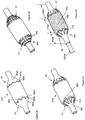
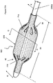
- FIGS 1A and 1B illustrate a shell 678.
- the shell 678 can have a shell longitudinal axis 26.
- the shell 678 can have a shell wall 684 with an average shell thickness 686.
- the shell 678 can be a tube or a sheath or combinations thereof.
- FIG. 1B illustrates a cross section A-A oF shell 678.
- the shell can have a shell proximal stem 30 and/or a shell proximal taper 34 and/or a central section 38 and/or a shell distal taper 42 and/or a shell distal stem 43.
- the shell 678 can have shell length 28.
- Shell length 28 may be the sum of lengths 32, 36, 40, 44 and 45.
- the shell proximal stem 30 has a shell proximal stem length 32.
- the proximal stem length 32 can be from about 3 mm to about 15 mm, more narrowly about 10mm.
- the shell proximal taper 34 may have a shell proximal taper length 36.
- the shell proximal taper length 36 can be from about 0 mm to about 25 mm, more narrowly from about 10 mm to about 22 mm, yet more narrowly from about 16 mm to about 20 mm.
- the shell central section 38 may have a central section length 40.
- the central section length 40 can be from about 0 mm to about 55 mm, more narrowly from about 30 mm to about 50 mm.
- the shell proximal taper 34 may have a shell proximal taper length 44 from about 0 mm to about 25 mm, more narrowly from about 10 mm to about 22 mm, yet more narrowly from about 16 mm to about 20 mm.
- the shell distal stem 43 may have a shell distal stem length 45.
- the distal stem length 45 can be from about 3 mm to about 15 mm, more narrowly about 10mm.
- the shell length 28 can be from about 10mm to about 250 mm, more narrowly from about 50mm to about 150mm, still more narrowly about 75mm to about 125mm
- the shell 678 can have a shell central section outer diameter 50.
- the central section 38 may have a shell inside radius 706 and a shell outside radius 708. Diameter 50 may be twice shell outside radius 708.
- the central section 38 may be cylindrically shaped, as shown.
- the shell central section outer diameter 50 can be from about 2mm mm to about 40 mm, more narrowly about 8mm to about 30mm, still more narrowly from about 16mm to about 28mm, for example 26, 4, 22 or 20mm.
- the central section 38 may have a shell outside radius 708.
- the shell outside radius 708 can have a maximum dimension at the longitudinal location where the central section 38 meets the tapers 34 or 42.
- the shell outside radius 708 can have a minimum dimension in the longitudinal center of the central section 38.
- the shell 678 can have a shell proximal stem diameter 31.
- the shell proximal stem diameter 31 can be from about 0.5mm to about 8mm, more narrowly about 1mm to about 5mm, for example about 3mm.
- the shell 678 can have a shell distal stem diameter 41.
- the shell distal stem diameter 41 can be from about 0.5mm to about 8mm, more narrowly about 1mm to about 5mm, for example about 3mm.
- the shell 678 can have one or more neck sections adjacent to and extending from the central section 38.
- a proximal neck section can be a shell proximal taper 34 extending proximally from the central section 38.
- a distal neck section can be a shell distal taper 42 extending distally from the central section 38.
- Each of the neck sections can have a neck first end 60 and a neck second end 62.
- the neck first end 60 can have identical or different dimensions that the neck second end 62.
- the neck first end 60 may be adjacent to the central section 38.
- the neck first end 60 can have a neck first end diameter 61.
- the neck second end 62 can have a neck second end diameter 63.
- the neck first end diameter 61 can be larger than the neck second end diameter 63.
- the neck sections can be tapered, conical, multi-splined (e.g., having a plurality of concave and a plurality of convex portions on each neck section), or combinations
- the shell 678 can have an inner lumen 154A and an outer lumen 154B.
- Inner lumen 154A may be formed by second hollow shaft 2000B.
- Inner lumen 154A may provide a lumen thru the entire shell.
- Inner lumen 154A may allow a guidewire to pass thru the interior of the shell.
- Outer lumen 154B may connect to balloon inflation/deflation ports 654.
- Outer lumen 154B maybe formed between the inner wall of first hollow shaft 2000A and the outer wall of second hollow shaft 2000B.
- the distal taper angle 90A can be from about 0 to about 90°, more narrowly about 50° to about 20°, yet more narrowly about 45° to about 30°, for example about 35°.
- the proximal taper angle 90b can be from about 0 to about 90°, more narrowly about 50° to about 20°, yet more narrowly about 45° to about 30°, for example about 35°.
- the first hollow shaft 2000a can have a hollow shaft distal port 54.
- One of the balloon inflation/deflation ports 654 can attach to the hollow shaft distal port 54.
- the shell 678 can be resilient (i.e., elastic) or non-compliant (i.e., inelastic).
- shell 678 may have a burst pressure of greater than 3atm, more narrowly, greater than 10atm, still more narrowly greater than 15atm. If shell 678 is configured to be patent and used as a balloon, the shell 678 may have a diametric elasticity of less than 0.35mm/atm, more narrowly less than 0.2mm/atm, still more narrowly less than 0.03mm/atm, still more narrowly less than 0.02mm/atm.
- the shell wall 684 can have high puncture strength. For example, when a shell 678 is pressurized to about 4atm and a 1mm gauge pin is driven into the balloon at about 1mm/sec, the pin may need to exert more than 13 newtons of force to puncture the balloon wall, more narrowly more than 18 newtons.
- the shell wall 684 can be non-compliant.
- the shell wall 684 can have a polymer.
- the shell wall 684 can be fluid-tight (e.g., non-porous enough to prevent water, and/or saline solution, and/or air transfer or osmosis through the shell wall 684).
- the shell wall 684 can have a wall thickness of about 0.04mm to about 0.8mm.
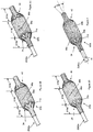
- FIG. 2A shows a shell 678 with first, second and third shell taper reinforcements 862a, 862b and 862c respectively in the proximal taper 34 and fourth, fifth and sixth shell taper reinforcements 862d, 862e and 862f respectively in the distal taper.
- Each of the shell taper reinforcements 862 may have different sizes, for instance different lengths.
- the shell taper reinforcements 862a, 862b, 862c in the proximal taper 34 can be asymmetrical with respect to the shell taper reinforcements 862d, 862e, 862f. For example, as shown in FIG.
- the shell taper reinforcements 862a, 862b, 862c in the proximal taper 34 can be longer and/or may form a semi-circle having a higher curvature than the shell taper reinforcements 862d, 862e, 862f.
- shell taper reinforcements 862 can be arranged such that a portion of each reinforcement 862 is visible.
- Shell taper reinforcements 862 may cover part or all of the shell tapers 34 and 42, stems 30 and 43 and central section 38.
- Shell taper reinforcements 862 may have shell taper reinforcement lobes 866.
- Shell taper reinforcement lobes 866 may have a semi-circular shape and extend in the shell longitudinal direction, as shown in Figure 2A .
- Shell taper reinforcements 862 may increase the stiffness of the shell wall 684 in areas covered by shell taper reinforcements 862. For example, either or both the neck sections 34 and/or 42 can have a greater stiffness than the central section 38.
- Shell taper reinforcements 862 may be panels 196.
- Wall 684 may comprise a polymer such as PET, Mylar, Nylon, Pebax, polyurethane or combinations thereof.
- FIG. 2B and 2D shows a shell 678 with shell apertures 714.
- Shell apertures 714 may penetrate the entire wall of the shell 678. Shell apertures 714 may release internal pressure from the shell 678 and may allow materials such as blood or air to cross the plane of the shell wall 684.
- the shell apertures 714 can be in fluid communication with the inside and outside of the shell 678.
- Shell apertures 714 may be circular (as shown in FIG. 2D ), elliptical (as shown in FIG. 2B ), rectangular, teardrop shaped, hexagonal or other shapes or combinations thereof.
- Shell apertures 714 may be located in the shell proximal stem 30, the proximal taper 34, the central section 38, the distal taper 42 or the shell distal stem 43 or combinations thereof.
- apertures 714 in shell 678 there may be less than 500 apertures 714 in shell 678, more narrowly less than 100, still more narrowly less than 25. For instance, there may be 1, 2, 3, 4, 5, 6, 7, 8, 9,10, 11, 12, 13, 14, 15, 16, 17, 18, 19, 20, 21, 22, 23 or 24 apertures 714 in shell 678.
- the shell apertures 714 can be arranged in axial and circumferential rows, i.e., to form a grid.
- apertures 714 can be arranged along axial lines 5100A, 5100B, 5100C, 5100D and circumferential lines 5102A, 5102B, 5102C, 5102D.
- the apertures 714 can be positioned at the cross-section of each line 5100, 5102. There can be, for example, between two and six circumferential lines 5102 at each end 34, 42 and between six and sixteen axial lines 5100.
- apertures 714 at each end 34, 42 there are twenty-four apertures 714 at each end 34, 42 positioned along three circumferential lines 5102 at each end 34, 42 and along eight axial lines.
- the apertures 714 and/or axial lines 5100 can be positioned substantially in between each outer pleat line 826 (and substantial along the inner pleat lines) to protect the apertures 714 and prevent exposed walls of the apertures 714 from catching during balloon delivery and removal.
- FIG. 2C illustrates that shell 678 may have teardrop shaped shell apertures 714 arranged along a single circumferential line at each end 34, 42 of the balloon.
- Shell apertures 714 may be cut through shell taper reinforcements 862.
- the portion of the edge of the shell aperture 714 that extends furthest towards the longitudinal center of the shell 678 may align with the part of the shell taper reinforcement lobe 866 that extends furthest towards the longitudinal center of shell 678 as shown in Figure 2C .
- the aperture 714 can be angularly aligned with lobe 866.
- apertures 714 can be shaped as squares ( Fig. 2H ) or trapezoids ( Fig. 21 ) with rounded edges.
- the apertures 714 can be configured in such a way as to provide maximum flow-through for a given space while still providing structural support. That is, while a teardrop shape may provide maximum flow-through while still folding within the pleats at the conical ends of the balloon, a plurality of different apertures along the same inner pleat line can provide substantially the same flow while providing additional structural support for the shell.
- each axial line 5100 (along the inner pleat line) can thus include, for example, between 2 and 8 apertures, such as between 3 and 4.
- the apertures can grow increasingly larger in diameter as they radiate from the base of the balloon up the cone towards the major diameter.
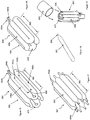
- the shell 678 can include a reinforcement 5700 having a proximal taper portion 5701 covering the proximal shell taper 34, a distal taper portion 5702 covering the distal shell taper 42, and strips 5703 extending between the proximal taper portion 5701 and the distal taper portion 5702.
- the proximal taper portion 5701, distal taper portion 5702, and strips 5703 can be made of the same material, such as a thin film.
- the thin film can be a panel 196 or a layer 72.
- the thin film can be less than about 0.004 inches thick, more narrowly, less than about 0.002 inches thick, still more narrowly less than about 0.001 inches thick.
- the proximal and distal taper portions 5701, 5702 can include shell taper reinforcement lobes 866 around apertures 714.
- a single strip 5703 can extend, for example, from each lobe 866.
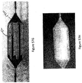
- the strips 5703 can run approximately parallel with the longitudinal axis of the shell 678 and can connect a lobe 866 on the proximal taper portion 5701 with an opposing lobe 866 on the distal taper portion 5702.
- the strips 5703 can have approximately the same width. In other embodiments, as shown in Figure 57B , the strips 5703 can have a varying width, such narrow towards the center of the shell 678 and widen at the proximal or distal ends.
- the reinforcement 5700 is formed in two separate patterns such that only one taper portion (here the distal taper portion 5702) has the strips 5703 connected thereto while the other taper portion (here the proximal taper portion 5701) does not include strips.
- the reinforcement 5700 can then be assembled over the shell 678 such that the strips 5703 are properly aligned (for example, such that the strips 5703 extend from the lobes 866 of the distal taper portion 5702 to the lobes 866 of the proximal portion 5701 without overlapping).
- each strip 5703 can have a curved section 5707 near its proximal end such that the edge 5705 of the strip meets the proximal portion 5701 at an angle.
- the curved section 5707 advantageously reduces the chances of having the edges 5705 of the strips 5703 catch during withdrawal of an inflatable medical device including the shell 678 from a patient.
- the strips 5703 can include slots or cuts 5709 therein, such as a plurality of cuts 5709 along the length of each strip 5703.
- Each cut 5709 can extend approximately perpendicular to the length of the strip.
- the cuts 5709 can advantageously allow the strips 5703 to be more flexible, thereby allowing the strips 5703 to bend more easily to conform to the surface of the shell 678.
- the reinforcement 5700 including proximal taper portions 5701, distal taper portions 5702, and strips 5703 therebetween can advantageously provide added longitudinal stiffness to the shell 678. Such added stiffness can help prevent buckling of the shell 678 under compression, which can otherwise by caused due to asymmetrical loading on the shell 678. Further, the strips 5703 can advantageously provide a smooth transition from the unreinforced zone to the reinforced zone of the shell 678 during withdrawal of the device from a patient. For example, the pullout force thru a standard introducer of an inflatable medical device including the shell 678 without the strips 5703 can be greater than 4 lbs, such as 4.5 lbs. Such high force can potentially require introducer removal and/or cause vessel damage.
- the pullout force with the strips 5703 can be reduced to less than 2lbs, such as between 1.5 and 1.9 lbs, e.g., 1.7 lbs or 1.8 lbs.
- the pullout force can thus be decreased by a factor of more than 2 by including the strips 5703.
- Such a low pullout force can reduce the likelihood of vessel damage during use.
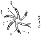
- the reinforcement 5700 is formed in two separate patterns such that only one taper portion (here the proximal taper portion 5802) has the strips 5703 connected therethrough while the other taper portion (here the distal taper portion 5801) does not include strips. Having the strips 5703 on the proximal side can advantageously help transition the balloon in and out of the introducer.
- Each portion 5801, 5802 can include radiating slits 5881 at the base to help the portions 5801, 5802 wrap around the base of the balloon.
- Strips 5703 can each have a distal taper portion 5819 configured to fit into notches 5817 on the portion 5801.
- the reinforcement 5700 can extend underneath or within one or more of the balloon layers.
- the reinforcement 5700 can be placed directly over a bladder 52 formed over a mandrel 230.
- successive fiber layers can then be placed thereover to fully cover the reinforcement 5700. Covering the reinforcement 5700 with one or more layers advantageously keeps the reinforcement 5700 in place and prevents the reinforcement 5700 from catching along a patient's anatomy when the device is in use.
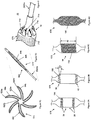
- Figures 3A , 3B, 3C and 3D illustrate that the shell 678 can have reinforcement fibers 86.
- Second or latitudinal reinforcement fibers 86a can be perpendicular to the shell longitudinal axis 26.
- Fibers 86a may be one continuous fiber wound around the part (a "hoop wind"). Fibers may be applied with a certain density. For example, fibers may be applied at 100 winds per 1 inch (25.4mm). The number of winds per inch is often referred to as the "pitch" of the wind. The pitch can vary across the length of the shell. Fibers 86a may be omitted entirely from portions of the shell 678.
- First or longitudinal reinforcement fibers 86b can be parallel with the shell longitudinal axis 26. Fibers can be applied with a certain density. For instance, there may be 50 fibers 86b per 1 inch (25.4mm) around the circumference of the shell 678. Fiber 86b density can vary around the circumference of the shell. Fibers 86b may be omitted entirely from portions of the shell 678.
- the angle between fibers 86a and 86b may be approximately perpendicular and may not change between inflation and deflation.
- Figures 3A , 3B, 3C and 3D show that the shell can have a longitudinal proximal zone 618a, a longitudinal central zone 618b and a longitudinal distal zone 618c.
- Proximal zone 618a may cover the proximal taper 34 and proximal stem 30.
- Distal zone 618c may cover the distal taper 42 and distal stem 43.
- Central zone 618b may cover the central section 38.
- Fibers 86a and/or 86b may be present or absent in zones 618a and/or 618b and/or 618c.
- the fiber 86a pitch may be different in each of zones 618a, 618b and 618c.
- the fiber 86a pitch may vary within each of zones 618a, 618b and 618c.
- the fiber 86b density may be different in each of zones 618a, 618b and 618c.
- the fiber 86b density may vary within each of zones 618a, 618b and 6
- Figure 3A shows that fibers 86a and 86b can be present in zone 618b. Fibers 86a and 86b may not present in zones 618a and 618c.
- Figure 3B shows that fibers 86b can be present in zones 618a, 618b and 618c. Fibers 86a may be present only in zone 618b.
- Figure 3C shows that fibers 86b and 86a can present in zones 618a, 618b and 618c.
- Figure 3D shows that the pitch of fibers 86a in zone 618b may be less than the pitches in zones 618a and 618c. The pitches in zones 618a and 618c may be substantially equivalent.
- the pitch in zones 618a and 618c may be 128 winds per inch, while the pitch in zone 618b may be 100 winds per inch.
- Lower pitch fibers 86 in one zone 618 may cause the shell wall to structurally fail in the lower pitch zone 86 before the pitch zones 86 with a higher fiber pitch.
- zone 618b can burst before zones 618a and 618c when the shell wall 684 experiences structural failure.
- Zones 618 with lower pitch may be more compliant and foldable than zones 618 with higher pitch.
- a zone 618 may have a 10% lower pitch than the remainder of the part, more narrowly a 20% lower pitch than the remainder of the shell wall 684.
- zones 618a and 618b and between 618b and 618c may move.
- the boundaries may be located in the shell tapers 34 or 42 or the central section 38.
- Second or latitudinal reinforcement fibers 86a may or may not be a continuously wound single fiber.
- first reinforcement fiber 85a can be at a first reinforcement fiber angle with respect to the shell longitudinal axis 26.
- first reinforcement fiber angle can be 10, 15, 20, 25, 50, 55 or 60 degrees to the shell longitudinal axis.
- Second reinforcement fiber 85b can be at a second reinforcement fiber angle with respect to the shell longitudinal axis 26.
- the second reinforcement fiber angle can be 10, 15, 20, 25, 50, 55 or 60 degrees to the shell longitudinal axis.
- Second reinforcement fiber 85b can have an equal but opposite angle to first reinforcement fiber 85a.
- first reinforcement fiber 85a can be at +20 degrees and second reinforcement fiber 85b can be at -20 degrees to the shell longitudinal axis.
- Third reinforcement fiber 85c can be substantially perpendicular to the shell longitudinal axis. Third reinforcement fiber 85c may be omitted from the shell wall 684.
- Figure 5 illustrates longitudinal reinforcement fiber 86b can be parallel with the shell longitudinal axis 26.
- Second longitudinal reinforcement fiber 87b can be parallel with the shell longitudinal axis 26.
- Fibers 86b and 87b can be separated by areas of missing longitudinal fiber 614. Areas 614 may separate fibers 86b and 87b by 2mm, more narrowly less than 1mm, still more narrowly less than 0.25mm. Areas 614 may be distributed on the shell surface such that no area longitudinally substantially overlaps any other area on the shell. Areas 614 may be distributed such that latitudinally adjacent areas do not have any longitudinal overlap.
- Areas 614 may be distributed in a regular, repeating pattern around the diameter of the shell sufficient to prevent any fiber from reaching from one end of the shell to the other while still maximizing the longitudinal strength of the shell.
- Fibers 86B and 87B may be less than 80% as long as the shell, more narrowly less than 75%, still more narrowly less than 70%, still more narrowly less than 65%, still more narrowly less than 60%.
- Second or latitudinal reinforcement fibers 86a can be substantially perpendicular to the shell longitudinal axis 26.
- Figure 6 illustrates that the longitudinal reinforcement fiber 86b can be parallel with the shell longitudinal axis 26.
- Second longitudinal reinforcement fiber 87b can be parallel with the shell longitudinal axis 26.
- Fibers 86b and 87b can overlap in reinforcement fiber overlap area 612.
- Reinforcement fiber overlap area 612 may form a hoop shaped area that can completely encircle the central section 38.
- Figure 7A illustrates that a shell 678 can be pleated to form flutes 84, for example four, five, six, seven or eight flutes 84, such as first flute 84a, second flute 84b.
- the flutes 84 can be made from accordion pleats, box pleats, cartridge pleats, fluted pleats, honeycomb pleats, knife pleats, rolled pleats, or combinations thereof.
- the pleating can be heat and/or pressure formed and/or the reinforcement fibers and/or panels can be oriented to form the flutes 84.
- Pleating the shell 678 may create first inner pleat line 822a and second inner pleat line 822b and outer pleat lines 826a between inner pleat lines 822a and 822b.
- Pleat lines 822 and 826 may be areas where the shell wall 684 can be creased.
- Inner pleat lines 822 may be positioned radially inward from outer pleat lines 826 when the shell is collapsed as shown in Figure 7A .
- Each flute 84 can be the portion of the shell wall 684 between two inner pleat lines 822.
- the shell apertures 714 can be between adjacent outer pleat lines 826 and interrupt an inner pleat line 822 as shown.
- the apertures 714 may or may not cross an inner pleat line 822.
- the apertures 714 may or may not cross an outer pleat line 826.
- Figure 7B illustrates a section view at D-D of Figure 7A .
- the portion of the section view that shows aperture 714 is highlighted with a dotted line.
- the width of aperture 714 at section D-D can be divided into aperture first partial width 830 and aperture second partial width 834.
- Aperture first partial width 830 may be about the same as aperture second partial width 834.
- the aperture 714 can be centered on the inner pleat line 822.
- the aperture first partial width 830 may be different than width 834, for instance equal to one to three times width 834, thus placing aperture 714 off center from inner pleat line 822.
- Aperture 714 can be wholly between two adjacent outer pleat lines 826, for instance between outer pleat lines 826a and 826b.
- Figure 7C illustrates a section view at E-E of Figure 7A .
- the central zone of the shell can have apertures or no apertures (as shown) interrupting the shell wall 684, as shown at section E-E.
- Figure 7D illustrates that the pleated shell 678 or annular balloon structure 682 can be collapsed into a compact form with a reduced diameter.
- Pleating may allow the shell 678 or structure 682 to collapse and expand in a repeatable and regular way.
- apertures 714 may be wholly (as shown) or partially covered or concealed by collapsed flutes 84, for instance second flute 84b may cover or conceal aperture 714. Covering the apertures 714 may give the collapsed shell 678 or annular balloon 682 an outer surface free of interruptions from the apertures 714.
- the diameter of the structure can be minimized and the apertures can be covered by the structure surface before and during insertion of the structure into the body during a medical procedure.
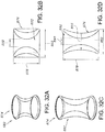
- Figures 58A-D illustrate a section view of a shell 678 having reinforcements 5700 (including a proximal taper portion 5701, distal taper portion 5702, and strips 5703 as discussed above with respect to Figures 57A-D ).
- the strips 5703 can be configured such that they are aligned with the flutes 84 and/or are aligned entirely between the inner and outer pleat lines 822, 826.
- the strips 5703 can all be positioned on a single side of each flute 84 and can all face in the same direction (clockwise in Figures 58A-58B and counterclockwise in Figure 58D ).
- the strips 5703 can be located only on the convex surfaces of the flutes 84 (as shown in Figures 58A-58B ) while in other embodiments, the strips 5703 can be located only on the concave surfaces of the flutes 84 (as shown in Figure 58D ).
- the strips 5703 can be located on both sides of each flute 84 (as shown in Figure 58C ).
- the strips can each have a width that is between 10 and 95% of the width of the flute 84 (i.e. the length from the inner pleat line 822 to an outer pleat line 826), such as between 20 and 85% of the width of a flute 84, e.g., between 30 and 75%.
- the strips 5703 can have a width that is substantially smaller than a width of a flute 84.
- the strips 5703 can have a width that is nearly the same as the width of a flute 84 (as shown in Figure 58B ).
- the strips 5703 can be closer to the outer pleat line 826 than the inner pleat line 822 (as shown in Figures 58A and 58C ) or can be closer to the inner pleat line 822 than the outer pleat line 826 (as shown in Figure 58D ).
- the strips 5703 can be substantially centered between the an outer pleat line 826 and an inner plate line 822 (as shown in Figure 58B ).
- the strips 5703 can also be located underneath or within one or more layers of the balloon as shown in FIG. 58E ), such as under one or more fiber layers.
- the strips 5703 can be positioned between the bladder and the layers of fiber. Positioning the strips 5703 under fibers can advantageously help capture the strips 5703 to help prevent the strips 5703 from extending out of the balloon and/or getting caught on a patient's anatomy when in use.
- Placing strips 5703 between the pleat lines 822, 826 can advantageously provide memory and repeatability for folding of the shell 678. That is, the strips 5703 arranged between the pleat lines provide tighter, more compact, and more concise pleating and refolding of a shell 678 relative to a shell 678 without the strips 5703.
- Annular balloon structure 682 may be subjected to a first cycle and a second cycle of inflation and deflation. Annular balloon structure 682 may have the same number of pleats after first and second cycles of inflation and deflation. For example, the fold position angle of the pleats, and the number and location of the pleats can remain about constant after an inflation and deflation cycle.
- a material such as a gas or a liquid, may flow from the shell exterior 49 through shell apertures 714 on one taper of the shell (for instance, the distal taper 42), pass through the shell interior 47 and flow out of shell apertures 714 on the other taper of the shell (for instance, the proximal taper 34) to the shell exterior 49.
- Figure 8 shows that apertures 714 may be fitted with shell aperture unidirectional flow valves or flaps 718, for instance apertures 714 may be fitted with shell aperture flaps 718 on proximal taper 34.
- Shell aperture flaps 718 may be configured so that they will partially or completely cover apertures 714 when there is no material flowing through the shell interior 47 to the proximal end, for example, of the shell exterior 49.
- flaps 718 When material is urged to flow with sufficient pressure from the shell interior 47 to the shell exterior 49, flaps 718 may open to allow flow through apertures 714. When pressure is reduced or removed, flaps 718 may partially or completely cover apertures 714. Flaps 718 may act as one-way or two-way valves. For example, flow and flow pressure (e.g., of a body fluid such as blood) through the apertures 714 may be generated by a beating heart during a medical procedure. Flaps 718 may be a temporary or permanent replacement for a heart valve (such as the aortic valve) during a medical procedure.
- a heart valve such as the aortic valve
- Flaps may be made of a polymer film or be made similar to the shell wall 684 described herein or be made of a compliant material such as, for instance, an elastomer.
- the flap may be made integral to the shell by cutting the aperture 714 but omitting the circumferential cut, for example leaving a hinge 719.
- Figure 9A shows a pattern for a marker wire 190.
- Marker wire 190 may be wound around the shell 678.
- the marker wire 190 can partially cover the distal and proximal ends of the central section 38 of the shell 678.
- Figure 9B shows that marker wire 190 may be wound around the shell on both the distal 42 and proximal tapers 34 of the shell 678.
- the marker wire 190 may be wound up to the distal and proximal borders of the central section 38 without any substantial amount of the wire being placed in the central section 38.
- the marker wire may be wound in a helical pattern in both directions on the shell or be wound in a single direction.
- the marker wire crossing angle 191 between two layers of marker wire may be less than 20 degrees, more narrowly less than 10 degrees, still more narrowly less than 6 degrees.
- Figure 9C illustrates that the shell 678 can have a marker wire 190 wrapped over approximately the entire length of central section 38.
- the marker wire 190 may be centered on the central section 38.
- the marker wire 190 may cover only a portion of the central section 38. For instance, the marker wire 190 may cover more than 70% of the central section 38, more narrowly more than 80%, still more narrowly more than 90%.
- the marker wire 190 may cover a portion of the distal tapers 42 and proximal tapers 34.
- the marker wire 190 may cover 100% of the distal tapers 42 and proximal tapers 34, more narrowly more than 50%, still more narrowly more than 25%.
- the marker wire 190 may be a latitudinal reinforcement fiber 86a.
- Figure 9D illustrates that the shell 678 can have a marker wire 190 wrapped over substantially the whole length of the shell 678.
- the pitch of the marker wire 190 may be less than about 150 winds per 1 inch (25.4mm), more narrowly less than about 75 winds per 1 inch (25.4mm), still more narrowly less than about 25 winds per 1 inch (25.4mm), still more narrowly less than about 10 winds per 1 inch (25.4mm).
- the pitch of the marker wire 190 may be about 6, 5,4, 3 or 2 winds per 1 inch (25.4mm).
- Figure 10A illustrates that the shell wall 684 at section B-B or at other sections taken through a single wall of the shell can have a layer 72 that can have a fiber matrix.
- the fiber matrix can have one or more monofilaments 274 and one or more adhesives 208.
- the adhesive can remain flexible when cured or melted to form an annular balloon structure 682.
- a fiber matrix may comprise a layer 72 or a panel 196.
- the reinforcement fiber 85, 86 and 87 can be a monofilament 274 and/or a tow 270.
- a tow 270 may contain one or more monofilaments 274.
- Reinforcement fiber 86 can be a marker wire 190.
- a fiber matrix may have one, two or more reinforcement fibers 86 running substantially parallel to each other and embedded in an adhesive 208.
- the substantially parallel reinforcement fibers 86 may be positioned within the adhesive such that they are touching each other along their length.
- the substantially parallel reinforcement fibers 86 may be positioned such that there is adhesive separating each fiber along its length.
- Figure 10A illustrates a layer 72 with a fiber matrix having a layer width 210 in cross-section.
- the layer width 210 can include a number of monofilaments 274.
- the layer 72 can have a linear quantity fiber density measured, for example, as the number of fibers 86 per unit of layer width 210.
- the linear quantity fiber density can be equal to or greater than about 500 monofilaments 274 per inch, more narrowly equal to or greater than about 1000 monofilaments 274 per inch, more narrowly equal to or greater than about 2000 monofilaments 274 per inch, yet more narrowly equal to or greater than about 4000 monofilaments 274 per inch.
- the liner quantity monofilaments 274 density can be from about 1,000 monofilaments 274 per inch to about 2,000 monofilaments 274 per inch.
- the layer 72 with a fiber matrix can have a layer thickness 216 from about 1 ⁇ m (0.00004 in.) to about 50 ⁇ m (0.002 in.), more narrowly from about 8 ⁇ m (0.0003 in.) to about 25 ⁇ m (0.001 in.), yet more narrowly from about 10 ⁇ m (0.0004 in.) to about 20 ⁇ m (0.0008 in.).
- Monofilaments 274 or fibers 86 may have a non-circular cross section, for instance an oval cross-section.
- Part or all of shell wall 684 can have a volumetric quantitative density of monofilaments 274 measured, for example, as the number of monofilaments 274 per unit of area.
- the area quantity monofilaments 274 density can be equal to or greater than about 100,000 monofilaments 274 per square inch, more narrowly equal to or greater than about 250,000 monofilaments 274 per square inch, more narrowly equal to or greater than about 1,000,000 monofilaments 274 per square inch, yet more narrowly equal to or greater than about 4,000,000 monofilaments 274 per square inch.
- the area quantity of fiber can be about 25% of the area of a wall cross section, more narrowly about 50%, more narrowly about 75%.
- the ratio of the volume of a fiber matrix to the volume of the monofilaments 274 can be about equal to or greater than about 15%, more narrowly equal to or greater than about 30%, more narrowly equal to or greater than about 50%, yet more narrowly equal to or greater than about 75%.
- Figure 10B illustrates that the outer layer 72a and the inner layer 72b can be polymer films, for example as described infra.
- the polymer films can be the same or different polymers, or any combination thereof.
- the first middle layer 72c can have a fiber matrix, for example with the fibers oriented as longitudinal fibers 86b.
- the second middle layer 72d can have a fiber matrix, for example with the fibers oriented as latitudinal or hoop fibers 86a.
- the third middle layer 72e can be an adhesive.
- the fourth middle layer 72f can be a radiopaque layer, such as a metal foil or wire.
- the layers 72c, 72d, 72e can be of varying lengths to provide a feathered transition to the main diameter (for example, as shown in Figure 11B , layer 72c can be longer than layer 72d, which can be longer than layer 72e).
- the layers 72c, 72d, 72e can be a single layer, such as a single layer of film.
- Figure 11A is a cross section taken at C-C in Figure 3C .
- Figure 11A illustrates that the outer layer 72a and the inner layer 72b can be polymer films, for example as described infra.
- the first middle layer 72c can have a fiber matrix, for example with the fibers oriented as longitudinal fibers 86b.
- the second middle layer 72d can have a fiber matrix, for example with the fibers oriented as latitudinal or hoop fibers 86a.
- the third middle layer 72e, the fourth middle layer 72f and the fifth middle layer 72g can be shell taper reinforcements 862. Shell taper reinforcements may be of unequal longitudinal lengths as shown in Figure 11A .
- An adhesive may be placed between any of the layers 72 shown. Any of the layers 72 shown in Figure 11A may be omitted.
- proximal taper 34 or distal taper 42 may have a first wall average shell thickness 686a.
- Central section 38 may a second wall average shell thickness 686b.
- First wall average thickness 686a may be greater than second wall average thickness 686b.
- the shell wall 684 of the proximal taper 34 and/or distal taper 42 can be the same or more stiff per unit of area than the shell wall 684 of the central section 36.
- the shell wall 684 of the proximal taper 34 and/or distal taper 42 can have a measured bending stiffness of about two, about three, or about five times greater per unit of area than the shell wall 684 of the central section 36.
- Figure 11B is a cross section taken at C-C in Figure 3C .
- Figure 11A illustrates that shell taper reinforcements 862 may be placed nearer to inner layer 72b than outer layer 72a.
- a layer 72 can be a panel 196.
- Layers 72 and/or panels 196 may comprise a polymer.
- the polymer may be a film.
- the thickness of the polymer films can be from about 2 m to about 50 ⁇ m, more narrowly from about 2 ⁇ m to about 18 ⁇ m, yet more narrowly from about 4 ⁇ m to about 12 ⁇ m.
- Films may be metalized or coated to change their surface properties. Metallization or coating may take place before or after a film is formed. Films may be treated chemically or via plasma or via corona treating or by combinations thereof in order to modify their bondability.
- a layer 72 and/or a panel 196 and/or a film may comprise polyamide, co-polyamide, polyester, co-polyester, ECTFE, Solef, EPTFE, FEP, Kapton, Pebax, HDPE, LDPE, PET, Mylar, micrton, nylon, PEEK, PEN (polyethylene Napthalate), Tedlar, PVF, Polyurethane, Thermoplastic Polyurenthane (TPU), Parylene or combinations thereof.
- the reinforcement fibers 86 can be high strength and inelastic. Inelastic fibers may have a strain to failure of less than 10%, more narrowly less than 5%. High strength fibers may have an ultimate tensile strength greater than 1.8 GPa (260 ksi), more narrowly greater than 2.4 GPa (350 ksi), still more narrowly greater than 2.9 GPa (420 ksi).
- the reinforcement fibers 86 can have a fiber or monofilament diameter 212, for example, from about 1 ⁇ m to about 50 ⁇ m, for example less than about 25 ⁇ m, more narrowly less than about 20 ⁇ m.
- the reinforcement fibers 86 may be a wire or wires.
- the reinforcement fibers 86 may be a metal.
- Wire may have a strain to failure of less than 10%, more narrowly less than 5%, still more narrowly less than 2%.
- the wire may be annealed or tempered to adjust its mechanical properties.
- the wire may have a breaking strength of greater than 150KSI, more narrowly greater than 250KSI, more narrowly greater than 400KSI
- Wire may be ductile and have a strain to failure of greater than 20%, more narrowly greater than 40%, still more narrowly greater than 80%.
- Ductile wire may allow the shell 678 the fold without fracturing the wire.
- the wire may be less than 25um in diameter.
- the wire may be substantially rectangular and less than 25um in thickness 1068, more narrowly less than 15um in thickness 1068 when integrated into the wall of the balloon.
- the ratio of the width 1072 of the wire to the thickness 1069 of the wire may be greater than or equal to about 3, more narrowly greater than or equal to about 5, more narrowly greater than or equal to about 10.
- the wire may be a foil wherein the ratio of the width 1072 of the wire to the thickness 1069 of the wire may be greater than or equal to about 100, more narrowly greater than or equal to about 300, more narrowly greater than or equal to about 500.
- the density of the wire may be greater than about 2.4 g/cm ⁇ 3, more narrowly greater than about 6.9 g/cm ⁇ 3, more narrowly greater than about 15 g/cm ⁇ 3.
- the reinforcement fiber 86 or wire may be substantially radiopaque when used under a fluoroscope as part of a medical procedure in the human body.
- the use of radiopaque material, such as radiopaque fibers 86 may allow the physician to use an inflation medium, such as saline, which is not radiopaque when inflating a balloon 650 or annular balloon structure 682.
- the use of radiopaque material, such as radiopaque fibers 86 may allow the physician to visualize how well pleated or folded the balloon structure 682 is when placed in the human body.
- the fibers 86 may be substantially radiolucent.
- a fiber matrix can have the same or different sizes and materials of fibers 86 within the same fiber matrix.
- the reinforcement fibers 86 or wires may be coated.
- the coating may enhance adhesion.
- the coating may be an adhesive 208.
- the adhesive 208 may be melted as part of the process of applying reinforcement fibers 86 to a shell 678.
- a reinforcement fiber 86 may comprise Vectran, PBO (p-phenylene-2,6-benzobisoxazole), Zylon, Spectra, Dyneema, UHMWPE, Conex, Technora, Twaron, Dacron, Polyester, Compet, Nylon, PEEK, PPS, Boron, Cermic, Kevlar, aramid, Carbon, Carbon Fiber, Inorganic Silicon, glass, fiberglass, Tungsten and its alloys, Tantalum and its alloys, Molybdenum and its alloys, bismuth and its alloys, gold and its alloys, silver and its alloys, platinum and its alloys, iridium and its alloys, stainless steel (for instance, alloys 302, 304, 316, 440), Nickel and its alloys, cobalt and its alloys, Titanium and its alloys, copper and its alloys, Barium and its alloys, bismuth and its alloys, Iodine and its alloys, Nitinol alloys or combinations thereof
- Adhesive 208 can be an thermoset material, a thermoplastic material, or a combination thereof. Adhesive 208 can be elastomeric. Adhesive 208 can be a polymer or a monomer or combinations thereof.
- the adhesive 208 can be a urethane, a polyurethane, a thermoplastic polyurethane (TPU), a thermoplastic, a cyanoacrylate, a UV curing adhesive, a polyester, a nylon, a polyamide, a silicone, a polypropylene, a polyolefm, ULDPE, VLPDE, LDPE, an epoxy, a pebax, Tefzel, an EVA, Solef, a parylene or combinations thereof.
- the adhesive 208 can be a resin or a glue.
- any of layers 72 or panels 196 can be leak proof, water tight, air tight, MMA (Methyl methacrylate)-resistant, MMA-releasing, or combinations thereof.
- Magnetic resonance visualization enhancement materials such as magnetic contrast agents, can be added to the adhesive 208 or any layer 72 or panel 196.
- the magnetic resonance visualization enhancement materials can enhance the visualization of the balloon during an magnetic resonance imaging (MRI) procedure.
- the magnetic resonance visualization enhancement material can be gadolium, Omniscan, Optimark, ProHance, Magnevist, Multihance, or combinations thereof.
- any of the layers 72 can be tinted or dyed a visible spectrum color.
- a pigment, coloring additive, dispersions or other coloring agents such as a coloring additive from Plasticolors (Ashtabula, Ohio) can be added.
- a paint or coating can be added to the outer surface of the shell 678.
- the color can be selected for branding, market differentiating, as an indication of the type of device, the size of the device, or combinations thereof.
- devices having a selected diameter, length, pressure rating, clinical indication or efficacy, other common performance metric, or combinations thereof can be dyed a specific color (e.g., green for a first type of device, red for a second type of device).
- the layers 72 can have one or more optical fibers.
- the fiber optic can be a strain sensor.
- the strain sensor can monitor mechanical status in real time.
- the fiber optic can guide light delivery into the body.
- the fiber optic can visualize a target site (e.g., gather light from the body to produce a visual image).
- Figure 11C is an exemplary cross section of an area of the balloon shown in Figure 57H that does not have a reinforcement 5700 while Figure 11D is an exemplary cross-section of an area of the balloon shown in Figure 57H that does have a reinforcement 5700.
- the outer layer 72a and inner layer 72b can include a polymer film, such as polyether ether ketone (PEEK).
- PEEK polyether ether ketone
- the outer layer can be a vapor deposited layer.
- the outer layer 72a can be over a first adhesive layer 208a, such as thermoplastic polyurethane (TPU).
- Beneath the first adhesive layer 208a can be a first middle layer 72c made of a fiber matrix, for example with fibers oriented as latitudinal or hoop fibers 86a within an adhesive 208b or resin, such as TPU.
- the first middle layer 72c can be over a second middle layer 72d made of a fiber matrix, for example with fibers oriented as longitudinal fibers 86b within an adhesive 208c.
- reinforcements 5700 can include a polymer film 5777, such as PET film, in between adhesive 208d, e.
- the reinforcements 5700 can be positioned between the inner layer 72b and the second middle layer 72d.
- Figure 12 shows that a balloon 650 can have a balloon main diameter 662, a balloon length 666 and a balloon wall thickness 658.
- the balloon may have a balloon taper section 652 at either end.
- the taper sections may connect the balloon diameter to the balloon inflation/deflation ports 654.
- the balloon 650 may be inflated by putting a pressurized fluid, such as saline, contrast, water or a gas, into both inflation/deflation ports or by putting fluid into one of the inflation/deflation ports 654 while closing the other inflation/deflation ports 654.
- a pressurized fluid such as saline, contrast, water or a gas
- Balloon 650 may have a main diameter 662 of about 1mm to about 15.3mm, more narrowly about 4mm to about 12mm, still more narrowly about 6mm to about 10mm.
- the balloon wall thickness 658 may be about 5 ⁇ m to about 50 ⁇ m, more narrowly about 8 ⁇ m to about 25 ⁇ m, still more narrowly about 8 ⁇ m to about 15 ⁇ m.
- the balloon length 666 may be about 125mm to about 635mm, more narrowly about 200mm to about 500mm, still more narrowly about 250mm to about 380mm.
- balloon 650 can have balloon segments 656a-656f.
- Balloon segments 656a-656f may form a continuous internal inflation/deflation lumen.
- Each balloon segment 656 may be joined by a balloon flexion section 670a-670e to the adjacent balloon segment 656.
- the balloon flexion sections 670 may have a smaller balloon flexion section diameter 664 than the balloon main diameter 662 (i.e., of the balloon segments 656).
- Balloon 650 may have a balloon flexion section diameter 664 of about 1mm to about 10mm, more narrowly about 2mm to about 6mm, still more narrowly about 2.5mm to about 5mm.
- Balloon 650 may have a balloon flexion section diameter 664 of about 3.3mm.
- Multi-segment balloon taper section 653 can connect the balloon flexion sections 670 to the balloon segments 656.
- the balloon 650 can bend or flex at the balloon flexion sections 670 before bending at the balloon segments 656, for example, when the balloon 650 is inflated.
- the balloon 650 could have 4, 5, 6, 7, 8, 9, 10 or more balloon segments 656.
- the balloon 650 may be made of one polymer, or use several layers or a mix of different polymers. Polymers such as Nylon, PEBAX, PET, parylene and /or polyurethane may be used to make the balloon 650.
- the balloon 650 may be fabricated by blow molding.
- the balloon may comprise a layer 72, a panel 196 or a film as described supra.
- Heat shrink tubing may be used to form the balloon 650.
- the balloon 650 could be formed by placing heat shrink tubing over a removable mandrel, heating the tubing and then removing the mandrel.
- the mandrel may be removed mechanically, with a solvent such as water, by the application of heat, or combinations thereof.
- the balloon 650 may be formed by depositing a material either onto a mandrel or into a cavity mold.
- the mandrel may be removed as described above or a mold may be opened to remove the balloon 650.
- Deposition could be by various techniques of physical vapor deposition, dipping, coating or spraying. Parylene may be deposited using a physical vapor deposition process.
- the balloon 650 may be deposited directly onto a mandrel with the shape shown in Figures 15, 16, 17 and 18 . The mandrel could then be removed.
- the balloon may comprise a fiber and be designed and fabricated as described in U.S. Provisional Application No. 61/363,793, filed 13 July 2010 , and in PCT Application No. PCT/US2011/43925, filed July 13, 2011 , both of which are incorporated by reference herein in their entireties.
- Figure 14A shows a balloon with balloon restraints 674 wrapped around the length of balloon 650.
- Figure 14B shows a balloon with balloon restraints 674 wrapped around the portions of the length of the balloon.
- the balloon restraints 674 may be bonded to the outside of the balloon.
- the restraints 674 may be knotted or tied around the balloon.
- the balloon restraints 674 may serve to narrow and bunch the balloon at the point they are applied, thus creating a balloon flexion section 670.
- a balloon flexion section 670 could also be created by locally twisting the balloon.
- Figures 15 and 16 show a balloon 650 after balloon segments 656 have been formed into an annular balloon structure 682 and inflated.
- the balloon segments can form a ring with a clear or hollow passageway or channel in the center.
- the annular balloon structure working length 680 can be the about equal to the longitudinal length of the largest diameter constant diameter section of each balloon segment 656.
- Working length 680 may be about 12mm to about 100mm, more narrowly about 25mm to about 75mm, still more narrowly 32mm to 65mm.
- Working length 680 may be about 45mm.
- the balloon segments 656 may be attached to each other with adhesive, solvent, the application of heat or combinations thereof.
- Figure 15 shows that the local balloon diameter of the flexed or relaxed (i.e., unfllexed) flexion section 670 can be less than the main balloon diameter of the balloon segments 656.
- Figure 16 shows a flexion section 670 where the balloon has been bent or folded with no previous narrowing of the balloon diameter.
- the balloon may be inflated by putting pressure into balloon inflation/deflations ports 654a and 654b.
- the inflation/deflation ports 654a and 654b may be joined into a single inflation/deflation port.
- First balloon segment 656a may have a first balloon segment longitudinal axis 657a.
- Second balloon segment 656b may have a second balloon segment longitudinal axis 657b.
- Balloon segment longitudinal axis angle 659 may be the angle between first balloon segment longitudinal axis 657a and second balloon segments longitudinal axis 657b.
- Balloon segment longitudinal axis angle 659 may be zero degrees to 200 degrees, more narrowly, 160 degrees to 200 degrees, for example 180 degrees.
- the longitudinal axis angle 659 can be the angle formed by the opposite terminal ends of the balloon flexion section 670 adjacent to the respective balloon segments 656.
- Figure 17 shows a group of inflated balloons 650 arranged into an annular balloon structure 682. Rather than sharing an inflation/deflation lumen, each balloon has two inflation/deflation ports 654.
- Figure 18 shows a balloon design with one inflation/deflation port and the other end closed.
- the balloon in 8B could be arranged into an annular balloon structure 682 similar to that shown in Figures 15, 16 and 17 .
- Balloons 650 may have their interior volumes connected together by piercing or punching holes in the wall of each balloon and then aligning the holes in each balloon before bonding the balloons 650 together.
- Figure 19 shows one method of forming the balloon 650 into an annulus.
- Adhesive 208 or a solvent may be applied to the outside of the balloon.
- the balloon 650 may be threaded around pins 676.
- the balloon flexion section 670 may be twisted about the balloon longitudinal axis, for instance 45 or 90 degrees.
- a compression fixture for instance a balloon assembly fixture compression sleeve 898 (e.g., a non-stick tube such as one made out of fluorinated ethylene propylene (FEP), such as Teflon) may be slid over the balloon 650 in order to hold and radially compress the balloon segments 656 together.
- FEP fluorinated ethylene propylene
- the balloon assembly fixture compression sleeve 898 may have an inside diameter smaller than the outside diameter of the annular balloon structure 682 shown in, for instance, Figures 15, 16 or 17 .
- a cross section of balloon 650 in balloon assembly fixture compression sleeve 898 may look similar to figure 24B with shell 678 being replaced by balloon assembly fixture compression sleeve 898. Heat may be applied to cure the adhesive 208 or to melt and fuse the segments 656 together.
- Figure 20A shows a balloon 650 after having been formed into a spiral to make an inflated annular balloon structure 682. That is, the balloon 650 forms a spiral ring with a central fluid passage 692 in the center.
- the coils of the spiral may be attached to each other with adhesive, solvent, the application of heat or combinations thereof.
- the balloon may be inflated by putting pressure into balloon inflation/deflations port 654. Multiple spiral coils may be interleaved to form one annular balloon structure.
- Figures 20B and 20C shows a spiral forming tool 742.
- the spiral forming tool has a spiral groove 746.
- a nominally straight balloon 650 may be wrapped around the spiral groove and pressurized.
- the pressurized assembly may be placed in the oven.
- the balloon dimensions may gradually creep until the balloon has been formed into the spiral shown in 11a.
- Figure 21 shows that the balloons 650 can have torroidal configurations.
- the balloons 650 can be stacked to make an annular balloon structure 682.
- the balloons 650 can form a ring with a clear passageway in the center.
- the balloons 650 may be attached to each other with adhesive, solvent, the application of heat or combinations thereof.
- the balloons 650 may be inflated by putting pressure into the balloon inflation/deflations port 654 (not shown).
- the lumens of each balloon 650 may be in fluid communication with one or more (e.g., all) of the other lumens and connected to one or more (e.g., all) of the other lumens internally.
- Figures 22A and 22B show the balloon 650 can be attached to a balloon strap 672.
- the balloon 650 can be in a spiral configuration.
- the balloon strap 672 may be removed during a medical procedure such that the balloon 650 may unwind along the first hollow shaft 2000a. This may make it easier to extract the balloon 650 thru an introducer after a procedure.
- An annular balloon structure may comprise a balloon 650 and a shell 678.
- Figure 23A shows that the inflated annular balloon structure can have a shell 678.
- the shell 678 may wrap, encircle or enclose the balloon segments 656.
- the shell 678 may entirely or partially (as shown) cover the balloon segments 656.
- Figure 23B shows a cross section F-F thru the center of the inflated annular balloon structure 682 in figure 23A .
- the annular balloon structure 682 can have a central fluid passage 692 that may allow the annular balloon structure 682 to perfuse when used in a lumen in the body.
- the annular balloon structure 682 can have an inside radius 690.
- This inside radius 690 can be 1 ⁇ 2 the maximum circular diameter that can pass through central fluid passage 692 of the annular balloon structure 682.
- the inside radius might be from about 2.5mm to about 10mm, more narrowly from about 5mm to about 7.5mm.
- the inside radius may be about 6.4mm.
- Figures 23B and 24B illustrate that the annular balloon structure 682 may have a first balloon cell 691a and a second balloon cell 691b.
- Figures 23B and 24B show a total of 8 balloon cells 691.
- Balloon cells 691a and 691b may be joined by balloon contact line 710. Similar balloon contact lines may exist between adjacent balloon cells 691 in figures 23B and 24B .
- the annular balloon structure 682 may have a balloon contact inner radius 694 and a balloon contact outer radius 698. These radii are aligned with the innermost and outermost extent of the contact between balloon cells 691a and 691b. The difference between the inner and outer contact radii can be about zero.
- the balloon cells 691a and 691b can be touching only at a point of tangency.
- the balloon contact inner radius and outer radius may be about 3.8mm to about 15mm, more narrowly about 7.5mm to about 11.5mm.
- the balloon contact inner radius and outer radius may be about 9.5.
- the balloon radius 704 can be the radius of the circle intersecting all of the center axes of each balloon cell 691.
- the balloon radius 704 may be about 5mm to about 15mm more narrowly about 5mm to about 13mm.
- the balloon radius 704 may be about 10mm.
- the shell wall 684 may have a shell average thickness 686 of about 7 ⁇ m to about 65 ⁇ m, more narrowly about 13 ⁇ m to about 38 ⁇ m, still more narrowly about 20 ⁇ m to about 30 ⁇ m.
- the shell outside radius 708 may be the shell inside radius 706 plus the shell thickness.
- the shell outside radius 708 may be equal to one half of the shell central section outer diameter 50.
- the balloon radius 702 may be about 0.5mm to about 7.6mm, more narrowly about 2mm to about 5.8mm, still more narrowly about 3mm to about 5mm.
- the balloon radius 702 may be about 3.8mm.
- the balloon cells 691 may have about zero contact with each other and with the inside of the shell 678 (as shown in figure 23B at shell contact line 712).
- the leakage area 700 between the inner wall of the shell and the balloon contacts 710 may be 12-22% of the total area enclosed by the shell cross section, more narrowly about 17%.
- the leakage area may be greater than 10%, more narrowly greater than 15%.
- Figure 24A shows an inflated annular balloon structure 682 with a shell 678.
- the shell 678 may entirely or partially (as shown) cover the balloon segments 656.
- the balloon 650 shown in figure 24A may have similar or identical dimensions to the balloon 650 shown in figure 23A .
- the shell 678 shown in figure 24A may have a smaller shell outside radius 708 than the shell 678 shown in figure 23A .
- the shell 678 in figure 24A may be placed over the balloon segments 656.
- the shell may compress or squeeze balloon segments 656 such that the balloon segments 656 may be deformed and driven closer to the shell longitudinal axis 26.
- the shell 678 may be in tension when the balloon segments 656 are inflated
- Figure 24B shows a cross section G-G thru the center of the inflated annular balloon structure 682 in figure 24A .
- the annular balloon structure can have a central fluid passage 692.
- the central fluid passage 692 can be an open channel along the entire length of the inflated annular balloon structure 682.
- the central fluid passage 692 may fluidly connect to apertures 714 in proximal taper 34 and distal taper 42.
- fluid such as blood
- gas such as air
- the balloon can perfuse when in the vasculature or in an airway.
- the annular balloon structure may have a second hollow shaft 2000b in the central fluid passage 692. There may be a flow area gap 693 between the second hollow shaft 2000b and the balloon 650.
- the flow area gap 693 might be from about 2 mm to about 10mm, more narrowly from about 4mm to about 7mm., for example 5.5mm.
- Second hollow shaft 2000b is not shown in Figures 23A, 23B and 24A .
- the inside radius 690 of annular balloon structure 682 shown in Figure 24B may be, for example, about 2.5mm to about 10mm, more narrowly about 3mm to about 5.6mm, for example about 4.3mm.
- the area of the circle defined by the inside radius 690 may be about 0.091 inches squared or about 0.59 centimeters squared.
- the balloon cells 691a and 691b may be joined by balloon contact line 710, for example with a bond.
- the annular balloon structure 682 may have a balloon contact inner radius 694 and a balloon contact outer radius 698. These radii are aligned with the innermost and outermost extent of the balloon contact 710 between balloon cells 691a and 691b.
- the balloon contact inner radius 694 may about 1mm to about 20mm, more narrowly 2.5mm to about 13mm, more narrowly about 5mm to about 7.5mm.
- the balloon contact inner radius may be about 6.4mm.
- the balloon contact outer radius 698 may be about 2mm to about 20mm, more narrowly 5mm to about 15mm, more narrowly about 7.6mm to about 12.7mm.
- the balloon contact outer radius may be about 10mm.
- Balloon contact line 710 can have a contact length about equal to the inner radius subtracted from the outer radius
- the balloon cell perimeter 696 is about equal to the total length of the dotted line 696 shown in Figures 23B and 24B (the dotted line matches the wall of the balloon cell 691).
- Balloon cells 691 may have a balloon cell perimeter 696 of about 3mm to about 48mm, more narrowly about 12.7mm to about 37mm, still more narrowly about 19mm to about 32mm, for example about 24mm.
- the length of the balloon contact line 710 may be greater than about 5% of the balloon cell perimeter 696, more narrowly greater than about 10%, still more narrowly greater than about 12%, for example about 16%.
- the balloon outer radius 702a may be about 0mm to about 5mm, more narrowly about 0.5mm to about 3mm, still more narrowly about 1mm to about 2.5mm, for example about 1.5mm.
- the balloon inner radius 702b may be about 0.51mm to about 7.5mm, more narrowly about 1mm to about 5mm, still more narrowly about 1.5mm to about 3.8mm, for example about 2.5mm.
- the leakage area 700 between the inner wall of the shell 678 and the balloon contact line 710 may be less than about 15% of the total area enclosed by the shell cross section, more narrowly less than about 10%, still more narrowly less than about 5%, for example 2%.
- the leakage area 700 can be sealed (no fluid communication) from central fluid passage 692.
- the leakage area 700 can be connected to a pressure source accessible by the physician.
- Leakage area 700 may contain a fluid, for instance, a drug.
- Shell wall 684 may have pores, for instance holes less than 0.005mm in diameter. Shell wall 684 may perfuse from shell interior 47 to shell exterior 49. Pressurizing the fluid in leakage area 700 may cause the fluid in area 700 to travel from shell interior 47 to shell exterior 49.
- the arc length of the shell contact line 712 may be about 1.3mm to about 10mm, more narrowly about 3.3mm to about 8.4mm, still more narrowly about 4mm to about 7.5mm, for example about 5.8mm.
- Figure 24b illustrates that the balloon cells 691 at the shell contact line 712 can be concentric with the shell 678, for example with the shell inner perimeter.
- the length of the wall of the balloon cells 691 at the shell contract line 712 can be equal to or greater than about 5%, more narrowly equal to or greater than about 10%, yet more narrowly equal to or greater than about 20%, of the balloon cell perimeter 696 (i.e., the total length of the wall of the balloon cells in lateral section, i.e., the section shown in Figure 24b ).
- the shell inner perimeter in a plane can be about equal to the shell inside radius 706 multiplied by 2 multiplied by pi.
- the sum of the arc lengths of all the shell contact lines 712 in a plane in the annular balloon structure 682 may be greater than 30% of the shell inner perimeter, more narrowly greater than 45%, still more narrowly greater than 55%, for example 61%.
- a bond may be formed between the balloon segment 656 and the shell 678 at the shell contact line 712 with adhesive, solvent, heat or combinations thereof.
- the shell 678 may have adhesive 208 on the shell inside surface, for instance a thermoplastic or a thermoset.
- the arc length of the shell contact line 712 may be greater than 10% of the balloon cell perimeter 696, more narrowly greater than 15%, still more narrowly greater than 20%, for example 24%.
- a support strap 5911 (or support straps) can extend in between each of the cells 691 of the balloon structure 682.
- the support strap 5911 can include a thin film, such as a film that is less than 0.005 inches thick, more narrowly less than 0.002 inches thick, still more narrowly less than 0.001 inches thick.
- the support strap 5911 can include fiber which may strengthen the thin film.
- the support strap 5911 can be configured so as to act as a tensile strap to transfer the load from between the cells 691 to the strap 5911.
- the support strap 5911 can be made of one continuous piece of material that extends through the center of the balloon structure and around the outside of one or more cells 691 (as shown in Figures 59A-59C ).
- the strap 5911 can be arranged so as to extend across two cells along the inner circumference of the balloon structure 682, loop around the outside of one cell 691, and then extend across two cells again along the inner circumference of the balloon structure 682.
- each cell 691 will have at least one strap extending around the outside after the strap 5911 is fully wound.
- the straps 5911 can extend across three cells along the inner circumference of the balloon structure 682, loop around the outside of one cell 691, and then extend across three more cells 691 along the inner circumference of the balloon structure 682. In this arrangement, only every other cell will have a strap 5911 around the outer circumference (assuming that there are an even number of cells 691).
- the strap 5911 can extend around the outside of one cell 691 and then extend through the center of the balloon structure 682 to wrap around the opposing cell 691in a bicycle spoke pattern. In other embodiments, the strap 5911 can wrap around the outside of two or more cells.
- the strap 5911 can be non-continuous and can extend only through the center and between one or more of the cells 691, but not around the outside of the cells (as shown in Figure 59D and 61 ).
- the strap 5911 can be cut at least part way in between neighboring cells 691 such that the strap 5911 does not wrap fully around the outer perimeter of the cells 69.
- two straps 5911A, B can each be cut in at least part way in between neighboring cells 691 such that the strap 5911 does not wrap fully around the outer perimeter of the cells 691, but rather forms individual strap pieces 5912a-h. It is to be understood that other arrangements of straps 5911 are possible.
- the support straps 5911 can be narrower than the length of the balloon structure 682. In such configurations, the support straps 5911 can extend around the entire balloon structure 682 more than once so as to support the entire length of the balloon structure 682.
- the straps 5911 can be angled longitudinally so as to spiral along the length of the balloon structure 682, thereby allowing the pattern to continue without having the strap 5911 catch on itself as it loops around the cells 691.
- the strap 5911 can be arranged substantially perpendicular with the longitudinal axis of the balloon structure 682, and there can be multiple straps 5911 placed along the length of the balloon structure 682 to support the entire balloon structure 682. Further, referring to Figure 60C , in some embodiments, multiple straps 5911A, 5911B, 5911C, 5911D, 5911E, 5911F can be placed along the longitudinal axis of the balloon. In one embodiment, one strap 5911A is woven around balloons to bridge the gap between four pairs of cells 691.
- Another strap 5911B is woven directly below the strap 5911 on the opposite four sets of balloons (see also Figure 61 ). This arrangement can be repeated down the length of the balloon. For example, as shown in Figure 60C , there can be three sets of two straps. Once attached, the individual straps 5911A, 5911B, 5911C, 5911D, 5911E can be cut along the backside to form individual strap pieces 5912a-h for each pair of straps (i.e., in this specific example, there will be 4 strap pieces 5912 for each strap 5911 and eight strap pieces 592 for each pair of straps), as shown in Figure 61 .
- the support strap 5911 (or support straps 5911), because it extends between neighboring cells 691, can advantageously prevent cells 691 from shearing and popping as they rub against one another.
- the support strap 5911 (or support straps 5911) can further provide increased radial stiffness when the balloon structure 682 is inflated, as the presence of the strap 5911 through the center of the balloon structure 682 can provide a load-bearing function.
- a support strap 5911 can be adhered to itself and/or to the underlying balloon 650 in a configuration that provides sufficient flexibility of the cells 691 and straps 5911 or strap pieces 5912 relative to one another while still providing the support function of the strap 5911 or straps 5911.
- an adhesive 5917A can be positioned so as to adhere the strap pieces 5912 between neighboring cells (such as cells 691A and 691B) while another adhesive 5917B can be positioned so as to adhere the strap 5911 to the underlying balloon 650 and/or coating 5931 on the balloon 650 (as described further below).
- a third adhesive 5917C can adhere the outer shell 678 to the balloon 650 and/or coating 5931 on the balloon 650.
- the straps 5911 or strap pieces 5912 can thus be bonded both to the cells 691 and to one another at the point where the cells 691 are closest together and/or otherwise resting against one another.
- the straps carry tensile loads that created by eccentric loading, better distributing the loads so that they do not create locally high stress peel loads, which would destroy the balloons.
- multiple support straps 5911 can be created from a single sheet 5913 of film, such as Mylar.
- straps 5911A and 5911B can be cut, such as laser cut, from the sheet 5913.
- adhesive to attach the straps 5911 can be laid down in strips to coincide with the desired placement of the adhesive relative to the cells 691 and the straps 5911.
- strips 5921A and B of adhesive can be laid down prior to cutting the straps 5911.
- an outer coating can be applied to the balloon 650.
- a balloon 650 made, for example, of nylon or polyethylene terephthalate, can be coated with a balloon coating 5931.
- the balloon coating 5931 can be a material of a certain elongation, such as greater than 10%, greater than 100%, greater than 600%, or greater than 1000%.
- the balloon coating 5931 can be parylene, silicone, or polytetrafluoroethylene.
- the balloon coating 5931 can be deposited or otherwise applied to the balloon 650 before the balloon 650 is wound together and/or placed inside the shell 678.
- the balloon 650 can be wound together and placed inside the shell 678, as shown in Figure 61 .
- the coating can be applied after the balloon is woven together but before it is placed inside the shell.
- the balloon coating 5931 can advantageously help bond the balloon 650 to the shell 678.
- This balloon to shell interface is important because it joints two structures of different stiffness values. That is, if the balloon 650 is bonded directly to the shell 678, then in use, the shell 678 will pull or push on the balloon 650. In doing so, if too much local load is placed on the bond between the two, then the thin balloon 650 tends to structurally fail in that location, causing the entire balloon 650 to burst.
- the coating 5931 can protect the balloon 650 from bursting. If too much load is placed on the bond, then the coating 5931 will preferentially locally debond from the balloon 650, without instead ripping the balloon 650.
- the shell to coating bond can be stronger than the coating to balloon bond.
- the parylene thickness and surface tension can be chosen so as to ensure the desired debonding occurs (i.e., so that the coating provides some adhesion without ripping the balloon).
- the surface of the balloon 650 can be modified for better adhesion and/or higher surface energy.
- the surface of the balloon 650 can be etched, textured, or plasma treated (e.g., plasma etched or vapor phase silane treated).
- the surface energy of the balloon can be approximately 30 - 50 dynes/cm, such as 30, 35, 40, 45 or 50 dynes/cm.
- the surface of the parylene can also be treated or chosen so as to have a surface energy of approximately 30 - 50 dynes/cm, such as 30, 35, 40, 45 or 50 dynes/cm.
- the coating 5931 is used with the straps. In other embodiments, the coating is used without the straps 5911.
- Figure 25a shows an inflated spiral balloon 650 (such as shown in figure 20a ) with a shell 678.
- the shell 678 may wrap, encircle or enclose the balloon 650.
- the shell 678 may entirely or partially (as shown) cover the balloon 650.
- Figure 25b shows a longitudinal cross-section H-H of the annular balloon structure 682 shown in Figure 25A .
- Figure 26a shows an inflated spiral balloon with a shell 678.
- the balloon 650 shown in figure 26A may have similar or identical dimensions to the balloon 650 shown in figure 25A .
- the shell 678 shown in figure 26A may have a smaller shell outside radius 708 than the shell 678 shown in figure 25A .
- the shell 678 in figure 26A may be placed over the balloon 650.
- the shell may compress or squeeze balloon 650 such that the balloon 650 may be deformed and driven closer to the shell longitudinal axis 26.
- the shell 678 may be in tension when the balloon 650 is inflated.
- Figure 17b shows a longitudinal cross-section of a spiral balloon with a shell 678.
- Shell contact line 712 may be oriented in the longitudinal direction.
- Shell leakage area may be shaped like a spiral.
- FIGS 27A and 27B illustrate that the shell 678 can have a balloon 650 in the shell interior 47.
- Shell strut 716 may contain additional elements not included in the shell central section 38.
- shell strut 716 may comprise additional longitudinally aligned fiber and/or additional fiber at other angles to the longitudinal axis and/or an additional polymer film and or shell taper reinforcements 862.
- the polymer film may have a low coefficient of friction on the outermost surface, for example it may have a coefficient of friction of less than 0.25, more narrowly less than 0.15, still more narrowly less than 0.1.
- Proximal taper 34 and distal taper 42 may help to introduce and withdraw the annular balloon structure 682 through a standard vascular introducer.
- the tapers 34 and 42 may protect the balloon 650 from being damaged by rubbing on the vascular introducer or features, such as calcifications, in the body.
- the tapers 34 and 42 may guide the annular balloon structure 682 thru the introducer.
- Figure 27B shows cross section K-K of an inflated annular balloon structure 682.
- Figure 27D shows a close-up of a portion of Figure 27B .
- Balloon segments 656 can be compressed by shell 678.
- the annular balloon structure 682 can have a second hollow shaft 2000b, a third hollow shaft 2000c and a fourth hollow shaft 2000d.
- fourth hollow shaft 2000d can fit over the outsides of shafts 2000b and 2000c to make shafts 2000b and 2000c approximately coaxial.
- Shafts 2000b and 2000c may slide within in the inside diameter of shaft 2000d.
- Shafts 2000b and 2000c may be in fluid communication.
- a hollow shaft gap 2002 is formed between the distal end of shaft 2000b and the proximal end of shaft 2000c.
- Figure 27C shows figure 27B with the annular balloon structure 682 in a deflated state.
- Figure 27E shows a close-up of a portion of Figure 27C.
- Figure 27E shows that shafts 2000b and 2000c move within the inside diameter of shaft 2000d when the annular balloon structure 682 is deflated.
- Hollow shaft gap 2002 increases when the annular balloon structure 682 moves from an inflated to a deflated state.
- the second hollow shaft 2000b, third hollow shaft 2000c and fourth hollow shaft 2000d can form an inner lumen 154a.
- the inner lumen 154a can extend thru the center of the annular balloon structure 682.
- a guidewire may be inserted into inner lumen 154a to locate the balloon during a medical procedure.
- Third hollow shaft 2000c and fourth hollow shaft 2000d may be omitted and second hollow shaft. 2000b may extend to catheter tip 838.
- First hollow shaft 2000a may be in fluid communication with hollow shaft distal port 54 and balloon inflation/deflation ports 654.
- the addition of fluid or gas into ports 654 may cause balloon segments 656 to inflate and for the annular balloon structure 682 to expand. Removal of fluid or gas from ports 654 may cause balloon segments 656 to deflate and for the annular balloon structure 682 to return to a pleated state, for example as shown in figure 7C .
- Figure 28A shows cross section K-K of an inflated annular balloon structure 682.
- Figure 28C shows a close-up of a portion of Figure 28A .
- the annular balloon structure can have a second hollow shaft 2000b that slidably fits into catheter tip 838.
- a hollow shaft gap 2002 is formed between the distal end of shaft 2000b and the catheter tip pocket bottom 840.
- the catheter tip 838 may have a catheter tip exit 841.
- Fluid flow 870 (shown with a dashed line in Figure 28A ) may pass through shell apertures 714 on the distal taper 42 or proximal taper 34, into central fluid passage 692 and through shell apertures 714 on the proximal taper 34 or distal taper 42.
- Figure 28B shows figure 27A with the annular balloon structure 682 in a deflated state.
- Figure 28D shows a close-up of a portion of Figure 28B.
- Figure 28D shows that shaft 2000b moves within the catheter tip 838 when the annular balloon structure 682 is deflated.
- Hollow shaft gap 2002 increases when the annular balloon structure 682 moves from an inflated to a deflated state.
- the second hollow shaft 2000b can form an inner lumen 154a.
- Inner lumen 154a may be in fluid communication with the catheter tip exit 841.
- Figure 28A shows that balloon flexion sections 670 may stay within the volume enclosed by shell central section 38 with central length 40.
- Figure 27B shows that balloon flexion sections 670 may touch the shell wall 684 in taper sections 42 and 34.
- Figures 29 and 30 show that the annular balloon structure 682 can have 2,3,4,5,6,7,8 or more support members 722 and/or support sheets 726.
- the support members 722 and/or support sheets 726 may cross the central fluid passage 692.
- Support members 722 and/or sheets 726 may be anchored to balloon segments 656 and/or second hollow shaft 2000b. Sheets 726 may be notched or forked so that they may pass by each other.
- Support members 722 and/or sheets 726 may be constructed similarly similar to the shell wall 684 and be substantially non-compliant.
- Support members 722 and/or sheets 726 may be semi-compliant, compliant or highly compliant.
- Support members 722 and/or sheets 726 may made of an elastomer such as urethane.
- Support members 722 and/or sheets 726 may comprise a fiber. Support members 722 and/or sheets 726 may have a strain to failure of less than about 10%. Support members 722 and/or sheets 726 may be in tension when the annular balloon structure 682 is inflated and serve to control the maximum diameter of the annular balloon structure 682 when inflated. When pressure is withdrawn from the annular balloon structure 682, support members 722 and/or sheets 726 may help to collapse the structure 682 in a way that helps pleats or flutes to re-form. The re-forming of pleats or flutes may make the collapsed balloon easier to withdraw through body lumens, for example through the vasculature and through an introducer.
- Figures 31A show that a valve 730 may be placed in central fluid passage 692.
- Figures 31A and 31B show the valve 730 in a closed position.
- Figure 31C shows the valve 730 in an open position.
- the valve leaflets 734 may be anchored to the balloon segments 656 or the inside of the shell wall 684.
- the valve leaflets can be thin and flexible. The valve leaflets may contact the outside of second hollow shaft 2000b when in a relaxed state.
- central fluid passage 692 may be filled with a liquid or a gas.
- valve leaflets 734 may open (as shown in Figures 31A and 31C ) to allow fluid flow 870 through the central fluid passage.
- the valve leaflets 734 may shut and reduce or eliminate fluid flow in central fluid passage 692.
- Valve leaflets 734 may act as a one way valve. A pressure difference in the liquid or gas between the distal taper 42 and the proximal taper 34 pressure may be generated by a beating heart during a medical procedure.
- Valve leaflets 734 may serve as a temporary replacement for a heart valve (such as the aortic valve) during a medical procedure.
- Valve leaflets 734 may be made of a polymer film or be made similar to the shell wall 684 or be made of a highly compliant material such as, for instance, an elastomer.
- the exterior of shell wall 684 may be coated with a drug, such as paclitaxil.
- the drug may be delivered to the body when the annular balloon structure 682 is inflated during a medical procedure.
- Layer 72 or panel 196 may comprise a drug.
- Layer 72 or panel 196 could be a film soaked in a drug, a film with pores to hold drugs, a fiber matrix holding drugs or combinations thereof.
- Layer 72 may be an outer layer 72a, an inner layer 72b or a middle layer, such as 72c.
- FIG 32A shows a capsule 874.
- Capsule 874 may be an annular balloon structure 682.
- Figure 32B shows a cross section of the capsule 874 in Figure 32A .
- Capsule 874 may have a capsule length 878, a capsule diameter 882 and capsule inside diameter 890.
- Figure 32C shows a capsule 874 with hourglass shape on the outer diameter.
- Figure 32D shows a cross section of the capsule 874 in Figure 32C .
- Capsule 874 may have a capsule waist diameter 886.
- the capsule length 878 divided by the capsule diameter 882 may form a capsule length to width ratio.
- the capsule length to width ratio may be from about 10:1 to about 1:1, more narrowly from about 5:1 to about 1:1, more narrowly still from about 3:1 to 1:1.
- the capsule waist diameter 886 may less than about 90% of capsule diameter 882, more narrowly less than about 80% of capsule diameter 882, still more narrowly less than about 70% of capsule diameter 882.
- Figure 33A shows a capsule 874 with capsule taper section 894 and capsule inflation port 896.
- Providing material, such as a liquid or a gas, at capsule inflation port 896 may cause capsule 874 to inflate.
- Withdrawing material at capsule inflation port 896 may cause capsule 874 to deflate.
- Figure 33B shows that a first capsule 874a and a second capsule 874b may be aligned concentrically and in contact to form an annular balloon structure 682 with an hourglass shape.
- First capsule 874a may be inflated or deflated at first inflation port 896a.
- Second capsule 874b may be inflated or deflated at second inflation port 896b.
- the internal lumens of capsules 874a and 874b may be connected over a portion of the area where the capsules touch.
- Three, Four, Five or more capsules 874 may be joined to form an annular balloon structure 874.
- Figure 34 shows a capsule 874 in a pleated condition.
- Capsule 874 may have a distal taper 42 with a distal taper length 44 of about 0mm.
- Capsule wall 876 may comprise a fiber matrix, a layer 72 a panel 196 or combinations thereof.
- Figure 35a shows a fiber matrix with fiber 86 and adhesive 208. The fiber matrix in Figure 35a may be referred to as a unidirectional fiber matrix.
- Figure 35b shows a fiber matrix with reinforcement fiber 86a and reinforcement fiber 86b at an angle of about 90 degrees to each other.
- Figure 35C shows a fiber matrix with reinforcement fiber 86a and reinforcement fiber 86b placed at layer angle 738 to one another. Layer angle 738 may be from 45 to 70 degrees, more specifically 45, 50, 55, 60, 65, or 70 degrees.
- Figure 35D shows that the fiber matrix shown in Figure 35D may be combined with another unidirectional fiber matrix.
- Capsule 874 may have a non-compliant capsule diameter 882 when inflated.
- Figure 36 illustrates that the shell 678 can be partially or completely manufactured in a pressure chamber 219.
- the pressure chamber 219 can be in a pressure chamber case 218.
- the pressure chamber case 218 can have a case top 220a separable from a case bottom 220b.
- the case top 220a can have a case top port 222.
- the case bottom 220b can have a case bottom port 224.
- the case top port 222 can be in fluid communication with the top of the pressure chamber 219.
- the case bottom port 224 can be in fluid communication with the bottom of the pressure chamber 219.
- the case top can screw or otherwise tightly join to the case bottom.
- the pressure chamber case can have one or more o-rings (not shown) in o-ring seats 226.
- the pressure chamber can have a mandrel seat 228.
- the mandrel seat 228 can be configured to receive a mandrel 230.
- the mandrel seat 228 can have holes or pores. The holes or pores in the mandrel seat 228 can allow pressure from the case bottom port and the bottom of the pressure chamber to reach the top surface of the mandrel seat around the mandrel and/or directly under the mandrel.
- the mandrel 230 can have the inner dimensions of the shell 678.
- the mandrel 230 may be made from a low melting point wax or metal, a foam, some collapsing structure or an inflatable bladder.
- the mandrel 230 can be made from a eutectic or non-eutectic bismuth alloy and removed by raising the temperature to the melt point of the metal.
- the mandrel 230 can be a water soluble mandrel.
- the mandrel 230 can be made from aluminum, glass, sugar, salt, corn syrup, hydroxypropylcellulose, ambergum, polyvinyl alcohol (PVA, PVAL or PVOH), hydroxypropyl methyl celluslose, polyglycolic acid, a ceramic powder, wax, ballistic gelatin, polylactic acid, polycaprolactone or combinations thereof.
- a panel 196a may be positioned over the mandrel 230.
- the panel 196a may be a single layer or multiple layers.
- the panel 196a could be a layer of film and meltable adhesive 208.
- the panel 196a can be positioned with film on the side that touches the mandrel and adhesive on the radially outer side.
- Figure 37A illustrates that a positive pressure can be applied to the top 220a of the pressure chamber (e.g., through the case top port 222) and/or a negative pressure or differential pressure or suction or vacuum applied to the bottom 220b of the pressure chamber (e.g., through the case bottom port 224).
- the panel 196A can get sucked and/or pressed down and/or formed onto the mandrel 230.
- the first panel 196A can be smoothly fitted to the mandrel 230 and adhered to the mandrel at the first adhesive 208A.
- the first panel 196A can stretch and/or yield and or/deform.
- the first panel 196A can be have thinner after being stretched, yielded or formed.
- the first adhesive 208a can be water soluble.
- the first adhesive 208a can be sugar syrup. Heat may be applied to panel 196a before forming onto mandrel 230. Forming of one panel 196a may be done more than once on different sized mandrels before the panel 196a reaches the form shown in Figure 37A .
- Forming of panel 196a may also be accomplished with a mechanical die.
- the mechanical die may be heated and conform closely to the shape of the mandrel 230.
- the mechanical die may have a shape similar to the mandrel seat 228.
- the mandrel 230 and panel 196a can be mounted into a trimming jig. Any excess portion of the first panel 196a extending from the mandrel 230 can be trimmed with a blade, with a laser, with a water jet cutter, with a die cut tool or combinations thereof.
- the trimming jig can cover the mandrel 230 and the first panel 196a attached to the mandrel.
- Several panels 196a and/or layers 72 can be formed over the mandrel 230 and cut. The panels 196a and/or layers 72 may be trimmed at the same time or one at time.
- Figure 37B illustrates that the mandrel can have the excess area of the first panel 196a removed in preparation for attachment of the second panel 196b.
- a second adhesive 208b can be applied to the first panel 196a around the perimeter of the second panel's 196b contact area with the first panel 196a.
- the mandrel 230 can be seated in the mandrel seat 228 with the first panel 196a in the mandrel seat.
- Figure 37C illustrates that after the case top 220a is secured to the case bottom 220b, the positive and/or negative pressures can be applied to the pressure chamber as described infra.
- the second panel 196b can be smoothly fitted or pressure formed to or against the mandrel 230 and adhered to the first panel 196a at the second adhesive 208b. Adhesion can be accomplished by the application of heat.
- the first and second panels (196A and 196B) can form the inner layer 72b or bladder 52 of the shell wall 684.
- the inner layer may be leaktight.
- the inner layer may be capable of sustaining pressure. Multiple layers can be made by repeating the method described infra.
- the pressure chamber can be heated, for example, to decrease the viscosity of and decrease the modules of the panels 196.
- FIG 37D shows cross section L-L with the mandrel 230 omitted.
- Bladder 52 may have first internal seam 69a, second internal seam 69b inner layer first panel 74a, inner layer second panel 74b and inner layer 72b.
- the bladder 52 may be leaktight.
- Figure 38A shows the bladder 52 after being fit over a mandrel 230 (mandrel 230 is inside bladder 52 and not directly shown in Figure 38A ).
- the bladder 52 may be made slightly larger in diameter and/or longer in length than the mandrel 230 onto which the bladder 52 is fit. This may allow the bladder 52 to be reassembled on the mandrel 230 with an internal seam 66 that may be sealed.
- Figure 38A shows a longitudinal seam 66 running the length of the bladder 52.
- the seam 66 may be sealed with adhesive, by fusing, by heating, with a solvent or combinations thereof.
- the sealed bladder 52 may form the inner layer 72b of a shell 678 and be leak-tight. Seam 66 may be an external seam 66a or internal seam 66b.
- Figure 38B illustrates that the first bladder portion 52a can overlap at a lap joint or overlap (as shown), abut at an abutment, or flange with the second bladder portion 52b at the seam 66.
- Seam 66 may be angled, vertical or a spiral or combinations thereof.
- Figure 39A shows a cross section of a tow 270.
- the tow 270 may contain about 6, 25, 100, 500 or 1500 monofilaments.
- the tow 270 may have a tow height 271 and a tow width 272.
- the tow 270 may be approximately circular.
- the tow height 271 and tow width 272 may be about 0.025 mm (0.001 in) to about 0.150 mm (0.006 in), more narrowly about 0.050 mm (0.020 in) to about 0.100 mm (0.040 in), still more narrowly about 0.075 mm (0.003 in).
- the tow 270 may be loosely held together by a polymer finish (not shown).
- Figure 39B shows that tow 270 may contain a marker wire 190.
- Marker wire 190 may be circular, as shown, and radiopaque.
- Figure 39C shows the tow 270 after the tow 270 has been spread.
- the tow 270 may be flattened or spread by passing the tow 270 through a closely spaced set of rollers that form a narrow pinch gap.
- the tow 270 may be spread by pulling the tow 270 under tension over a set of rollers or pins. After spreading, the tow 270 may have a tow height 271 less than about twice the fiber height 1068, for example about the same as fiber height 1068.
- the fiber height 1068 and fiber width 1072 may be substantially unchanged after spreading.
- the fiber width 1072 and fiber height 1068 may be about 15 ⁇ m (0.0006 in), tow width 272 may be about 210 ⁇ m (0.008 in) and tow height 271 may be about 15 ⁇ m (0.0006 in).
- the marker wire 190 is not shown in figure 39C but may be present after the tow 270 has been spread.
- Figure 40A illustrates that a layer of fiber matrix can be made on a roller 232.
- the roller 232 can be configured to rotate about a roller axle 234.
- the roller 232 may have a diameter from about 100 mm to about 1,000 mm.
- the roller 232 may be made or coated with an anti-stick material such as a fluoropolymer.
- Figure 40B illustrates that a releaser 236, such as a release layer, can be placed around the circumference of the roller 232.
- the release layer can be a low friction film or coating.
- the release layer may be a thin and/or flexible fluoropolymer sheet.
- Figure 40C shows that an adhesive 208 can be placed on the releaser or directly onto the roller 232 (e.g., if no releaser 236 is used).
- the adhesive 208 may be a thermoplastic film.
- the adhesive 208 may be a thermoset adhesive.
- the adhesive 208 may be a solvated thermoplastic or thermoset.
- the adhesive 208 may have a backing film, such as paper.
- Figure 40D shows the application of the reinforcement fiber 86 to the roller 232.
- the fiber 86 may be unwound from a spool (not shown) and rolled onto the top surface of the adhesive 208. Before winding, the fiber 86 may be infused or coated with an adhesive 208, a solvent, or both. The coating may be a thermoplastic.
- the fiber 86 may have been previously flattened as detailed supra.
- the fiber 86 may have a non-circular cross section, such as a rectangle or an ellipse. Any coating or sizing on the fiber may have been removed using a solvent.
- the fiber 86 may be placed with a gap between each successive fiber wrap.
- the gap may be less than about 200 ⁇ m (0.008 in), more narrowly less than about 5 ⁇ m (0.0002 in).
- a heat source or a solvent may be used to fix the fiber 86 to the adhesive 208 (i.e., tack the fiber 86 in place on the adhesive 208), to melt or solvate a material onto the release layer 236, to melt or solvate a material on the fiber 86 or combinations thereof.
- a separate resistive heater, a laser, a source of hot air, or an RF welder may be used.
- a solvent such as methyl ethyl ketone or tetrahydrofuran may be used.
- the fiber 86 can be wound with a pitch of 3000 to 30 turns per 1 inch (25.4 mm).
- the pitch can be chosen based on the total size of the fiber 86 or tow 270 being applied and the chosen gap between each subsequent fiber 86 or tow 270 on the roller 232.
- Applications of a single monofilament 274, which may be a wire, can have pitches from about 2000 to about 100 turns per 1 inch (25.4 mm).
- Figure 40E shows reinforcement fiber 86 on top of adhesive 208 on top of release layer 236.
- Figure 40E may show a cross section after the operation shown in Figure 40D is performed.
- Figure 40F illustrates that the roller can be placed between a vacuum top sheet 238a and a vacuum bottom sheet 238b, for example in a vacuum bag.
- a vacuum seal tape 240 can surround the roller 232 between the vacuum bottom and top sheets 238b and 238a, respectively. Air can be removed from between the vacuum top and bottom sheets 238a and 238b and within the vacuum seal tape, for example by suction from a suction tube 242.
- the roller 232 can be heated, for example to melt or cure the adhesive 208.
- Roller 234 can be removed from the vacuum bag, for example after melting or curing of the adhesive is complete.
- Figure 40G shows the removal of the panel 196. For instance, a cut may be made substantially perpendicular to the fiber.
- the panel 196 may be peeled away from the release layer.
- the panel 196 may be substantially foldable and/or flexible.
- Figure 40H illustrates that the panel 196 of fiber matrix can be removed from the roller 232.
- the panel 196 can be peeled off the releaser 236.
- the panel 196 can be repositioned on the roller 232 at about 90 degrees to the layer's previous angle and additional reinforcement fibers 86 can be applied as shown in figure 39D. This may result in a panel 196 with fibers 86 running perpendicular to each other (e.g., a "0-90" layer, so called for the angle the two layers of fiber make with respect to each other).
- the panel 196 can be cut into a smaller panel.
- the panel 196 can be cut with a trimming jig, a laser, a water jet cutter, a die cut tool, or a combination thereof.
- Figure 41A shows that a panel 196 may have reinforcement fibers 86b oriented substantially parallel to panel longitudinal edge 332.
- the panel 196 can have a panel width 334.
- the panel width 334 can be about equal to the circumference of the shell 678 in the central section 38.
- the panel 196 can have a panel length 335.
- the panel length 335 can be greater than the shell length 28.
- the panel 196 can have a panel rectangular section 336 and one or more panel serrations 338a, 338b and 338c.
- Each panel serration 338a, 338b and 338c can have a portion of the panel 186 that forms a portion of the stem 30 or 43 and taper 34 or 44.
- Each serration 338a, 338b and 338c can have a serration edge 339a, 339b and 339c, respectively.
- the angle between the serration edges 339 and a line parallel to the reinforcement fibers 86b can be a panel serration angle 340.
- the panel serration angle 340 can be about 30°, about 20°, about 10°, or about 0°.
- a first panel serration 338a can be substantially in line with a second panel serration 338b.
- One or more fibers 86b may run from the terminal end of the first serration 338a to the terminal end of the second serration 338b.
- Figure 41B illustrates that longitudinal reinforcement fiber 86b can be parallel with longitudinal edge 332.
- Second longitudinal reinforcement fiber 87b can be parallel with the fiber 86b.
- Fibers 86b and 87b can be separated by fiber separation areas 614.
- the fiber separation areas 614 may separate fibers 86b and 87b by about 2 mm, more narrowly less than about 1 mm, still more narrowly less than about 0.25 mm.
- the fiber separation areas 614 may be distributed on the panel such that no area 614 substantially overlaps any other area in the X and/or Y direction.
- the fiber separation areas 614 may be positioned in the X and Y directions on the panel 196 in a pattern sufficient to prevent any fiber from reaching all the way across the panel rectangular section in the X direction.
- the shell 678 in figure 5 may be built in part with the panel 196 shown in figure 41B .
- Fibers 86b and 87b may have fiber lengths 88 less than about 80% of the shell length 28 more narrowly less than about 75% as long, more narrowly less than about 70% as long, still more narrowly less than about 65% as long, still more narrowly less than about 60% as long.
- Figure 41C shows that a panel 196 can have a panel rectangular section 336 and one or more panel serrations 338a, 338b and 338c.
- Panel serration 338b can be oriented in the Y direction substantially midway between panel serrations 338a and 338c.
- Panel serration 338b can be oriented in the Y direction substantially closer to either panel serrations 338a or 338c.
- the longest reinforcement fiber length 88 in panel 196 may be less than about 75% of the length 28 of the shell, more narrowly less than about 70%.
- Figure 42A shows that panel 196 may contain reinforcement fibers 85a and 85b arranged in a woven pattern.
- a woven pattern can have fibers 85a and 85b that alternately pass over and under each other.
- Figure 42B shows that the panel 196 may contain reinforcement fibers 85 in a braided configuration.
- Figure 42C shows that the panel 196 may contain reinforcement fibers 85 of various lengths in random orientations, sometimes referred to as chopped or chopper fiber.
- Figures 43A and 43B illustrate that a panel 196 may be applied to a mandrel 230 with none, one or more layers 72 on the mandrel 230.
- the panel 196 may be joined to layers 72 by the application of adhesive or by heat or by combinations thereof.
- the panel 196 when folded onto the shape of the mandrel 230 may give a substantially complete coverage of the mandrel 230 with minimal or no overlap of the panel 196.
- Panel rectangular section 336 may cover the shell central section 38.
- Panel serrations 338 may cover proximal taper 34, distal taper 42, proximal stem 30 and distal stem 43.
- a die may be used to press the panel 196 onto the shell 678.
- the die may be heated and the panel 196 may contain a thermoplastic.
- the die may melt the thermoplastic and adhere the panel 196 to the shell 678.
- the die may be shaped to match the mandrel 230 shape.
- the mandrel 230 may be rotated about its longitudinal axis to advance the next set of serrations 338 into place under the die.
- the die may again press two serrations 338 into place on the shell 678. Subsequent use of the die in this manner may attach substantially the entire panel 196 to shell 678 as shown in Figure 43B .
- Figure 44 illustrates that fiber 86 can be wound over the mandrel 230 or over shell 678.
- the fiber 86 may be continuous or discontinuous.
- the mandrel can be rotated, as shown by arrow 252, about the mandrel longitudinal axis 250 or shell longitudinal axis.
- the first spool 244a can be passively (e.g., freely) or actively rotated, as shown by arrow 254, deploying fiber 86 (shown) or tow 270.
- the fiber 86 Before or during winding, the fiber 86 may be infused or coated with an adhesive, a solvent, or both.
- the coating may be a thermoplastic.
- a fiber distal end can fix to the shell 678 or directly to the mandrel 230.
- the fiber 86a may be wound with a gap between each successive fiber wind.
- the gap can be less than about 200 ⁇ m (0.008in), more narrowly less than about 5 ⁇ m (0.0002in).
- the fiber 86 can be wound with a pitch of about 3000 to about 30 winds per 1 inch (25.4mm).
- the pitch can be chosen based on the total size of the fiber 86 or tow 270 being applied to the part from first spool 244a and the chosen gap between each subsequent fiber 86 or tow 270 on the part.
- Applications of a single monofilament 274, which may be a wire, can have pitches from about 2000 to about 100 turns per 1 inch (25.4mm).
- a tool arm 246 can be attached to a rotating tool wheel 248.
- the tool arm 246 can rotate and translate, as shown by arrows 256 and 258, to position the tool wheel 248 normal to and in contact with the shell 678.
- a second tool wheel 248' (attached to tool arm 246') can have a range of motion sufficient to apply pressure normal to the surface of a shell taper section.
- the tool wheel 248 can press the fiber 86 or tow 270 against the shell 678 and spread the monofilaments 274.
- the tool wheel 248 may help to adhere the tow 270 to the shell, for example by applying pressure and following closely the surface of the shell.
- the tool wheel 248 can be heated to soften or melt the material on the surface of the shell 678.
- Another heat source or a solvent may be used to tack the fiber in place, to melt or solvate a material on the shell, to melt or solvate a material on the fiber or combinations thereof.
- a separate resistive heater, a laser, a UV light source, an infrared light source, a source of hot air, or an RF welder may be used with our without the tool wheel 248 to attach the fiber.
- a solvent such as methyl ethyl ketone or tetrahydrofuran or alcohol or combinations thereof may promote adhesion of the fiber 86 and may be used with our without the tool wheel 248.
- the tool wheel 248 can be made of or coated with a non-stick material.
- the tool wheel 248 may not rotate.
- the tool wheel 248 may comprise a hard surface, for example carbide.
- a second spool 244b may deploy marker wire 190 during a winding operation. Second spool 244b may also deploy a reinforcement fiber 85 (not shown). Marker wire 190 (or reinforcement fiber 85) may be applied simultaneously with fiber 86 and/or tow 270 to the shell. Marker wire 190 may interleave with reinforcement fiber 86 to form a single fiber layer on shell 678. Marker wire 190 may be deposited on top bellow another existing fiber layer.
- the resulting layer deposited in Figure 44 can have a layer thickness 216 of from about 1 ⁇ m (0.00004 in) to about 50 ⁇ m (0.002 in), more narrowly from about 8 ⁇ m (0.0003 in) to about 25 ⁇ m (0.001 in).
- FIG. 36, 37A, 37B and 37C may be used to apply additional panels 196 or layers 72 to shell 678.
- additional panels 196 may be applied to form an outer layer 72a on the shell 678 as shown in Figure 45A .
- Figure 45B shows that a panel 196e can applied to the proximal end of the balloon.
- a panel 196f can be applied to the distal end of the balloon.
- the panels 196,e,f can be applied after a layer or panel of fiber has been placed on the shell.
- the panels 196e,f can be applied before a layer or panel of fiber has been placed on the shell.
- panels 196e and 196f may be applied to the bladder 52 as shown in Figures 37 and 38 .
- the panels 196e and 196f could be like those shown in figures 46A and 46B .
- Figure 46A shows a panel 196 with panel cutout 842 and panel lobe 846.
- Panel cutout 842 can be aligned on a shell 678 to form an aperture 714.
- Panel lobe 846 can be placed on a shell 678 to form a shell reinforcement lobe 866.
- Figure 46B shows a panel 196 with a panel cut 850.
- Panel cut 850 may allow the panel to form over shell 678.
- radiopaque dye or a radiopaque marker can be used to mark the panel 196 before or after it has been formed over the shell 678.
- the radiopaque dye and/or radiopaque marker can be used as markers during implantation and/or for brand marking.
- Figure 47 illustrates that a wash tube 264 can be inserted into a mandrel washout port 262.
- a dissolving or solvating fluid can be delivered through the wash tube and into the washout port 262.
- the mandrel can be removed by delivery of a fluid solvent such as water, alcohol or a ketone.
- the solvent may be applied during the consolidation process such that the solvent melts or partially softens the mandrel and concurrently pressurizes the bladder.
- the mandrel 230 can be removed by raising the mandrel to a melting temperature for the mandrel.
- the mandrel 230 can be removed by deflating the mandrel or by collapsing an internal structure.
- Figure 48A illustrates that the shell 678 may be placed in a shell mold 622 containing a shell pocket 624.
- the shell mold 622 may be porous such that substantial amounts of gas may be drawn from shell pocket 624 thru the wall of shell mold 622 and out into the surrounding atmosphere.
- the shell 678 may have a tube (not shown) placed in its inner volume that may extend out either end of the shell 622.
- the tube may be thin and very flexible.
- the tube may be a silicon rubber.
- a coating may be sprayed into mold 622 that bonds to the shell 678 during cure and forms an outer layer 72a on the shell 678.
- Figure 48B illustrates that the shell mold 622 may be closed around the shell 678. Pressure may be applied thru shell second fluid port such that the shell expands to contact the inside of shell pocket 624. Alternately, the tube (not shown) extending out either end of the shell may be pressurized to force the shell into contact with pocket 624.
- Figure 48C shows Pressure P inside the shell volume pressing the shell wall 684 outwards.
- Mold 622 may be placed in an oven and heated. Mold 622 may have built in heaters. The shell mold 622 may be placed under vacuum or placed in a vacuum chamber during heating. The shell mold 622 may have a texture, such as a texture created by abrading or sand blasting or bead blasting the shell mold 622. The texture may impart a texture to the outer layer 72b of the shell.
- Heating the shell under pressure may cause one or more layers 72 to melt and/or fuse and/or bond with adjoining layers 72. Melting under pressure may remove voids in the shell wall. The inner and outer films may not melt. Heating the shell under pressure may cause the walls of the shell 678 to fuse or laminate into one continuous structure.
- the shell outer layer 72a may be substantially smoothed by this process.
- the shell outer layer 72a may be permeable or perforated such that gas or other material trapped in the shell wall 684 during manufacture may escape when the shell is heated under pressure.
- the shell outside radius 708 may be very accurate and repeatable. For instance, at a given pressure, the outside radius 708 of a group of shells 678 may all be within about 2% (+/- 1%) of each other. For instance, if the nominal dimension of the outside radius 708 of the shell is about 12 mm at about 60 psi (414 kPa), all shells may have an outside radius 708 of about 11.88 mm to about 12.12 mm.
- a shell 678 can be clamped in a pleating tool with two, three, four, five or more removable pleating blocks. Heating the pleating blocks to about 80C and then pressing them against the shell 678 for about 1 minute causes the shell to become pleated or fluted.
- Commercial pleating machines such as folding machinery from Interface Associates (Laguna Niguel, CA) can also be used. A small amount of wax may be used to hold the pleated and folded shell into its desired shape.
- a balloon 650 may be placed in an insertion tool 854. Before being placed in the insertion tool 854, the balloon 650 may be coated in an adhesive 208 or a solvent.
- the insertion tool 854 may comprise a tube that will not adhere to most adhesives, for example the tube may comprise a fluoropolymer.
- Figure 49C shows that apertures 714 may be cut in the shell 678, for example with a laser 858.
- a shell 678 may be fabricated with apertures 714 already in place.
- Figure 49D shows that insertion tool 854 may be inserted through aperture 714 into shell interior 47. Insertion tool 854 may be inserted through the interior volume of shell proximal stem 30 or shell distal stem 43 or any other orifice in the shell 678. A cut in the shell 678 may be made to allow the insertion tool 854 into shell interior 47.
- Figure 49E shows that the insertion tool 854 can be removed leaving balloon 650 in the shell interior 47.
- Figure 49F shows that balloon 650 can be inflated inside shell 678. Adhesive 208 or a solvent or the application of heat may bond balloon 650 to the inner wall of shell 678 forming annular balloon structure 682.
- Figure 50 illustrates a balloon catheter.
- Inflation fluid may be provided by detachable syringe 472 thru catheter Y-fitting 634.
- Inflation fluid may flow between the inside wall of first hollow shaft 2000a and the outside wall of second hollow shaft 2000b.
- Inflation fluid may flow into the balloon 650 to inflate the annular balloon structure 682.
- a guide wire may be inserted at guidewire port 632 and pass thru the interior of the second hollow shaft 2000b.
- Figure 51 illustrates a cross section of an annular balloon structure 682 in a substantially deflated and pleated or folded configuration.
- the annular balloon structure 682 is shown in a tube 428 with a tube inside diameter 436 and a tube inside diameter cross sectional area 434.
- the annular balloon structure 682 may be inserted into the tube 428 without damaging the annular balloon structure 682.
- the tube 428 may be, for instance, an introducer or a balloon protection sleeve used to store the balloon.
- the compression ratio of the annular balloon structure 682 can be from about 3:1 to about 10:1, more narrowly from about 5:1 to about 7:1.
- the compression ratio can be the ratio between twice the shell outside radius 708 of the substantially inflated annular balloon structure 682 and tube inside diameter 436.
- an annular balloon structure 682 with shell outside radius 708 equal to about 12.2mm can be inserted into a tube 428 with a tube inside diameter 436 of about 4.8mm, more narrowly about 4mm still more narrowly about 3.6mm.
- the annular balloon structure 682 can have a packing density equal to or greater than about 40%, more narrowly greater than or equal to about 55%, yet more narrowly equal to or greater than about 70%.
- the packing density can be the percentage ratio between the cross sectional area of the walls of the annular balloon structure 682 and the tube inside diameter cross sectional area 434.
- the packing density and compression ratios for the annular balloon structure 682 can remain substantially constant and the wall strength of the annular balloon structure 682 can remain substantially constant with repeated insertions or withdrawals from tube 428 and/or inflations and deflations of the annular balloon structure 682, for example 10 or 20 or 40 insertions and withdrawals or inflations and deflations.
- the annular balloon structure 682 can have an unsupported burst pressure.
- the unsupported burst pressure is the pressure at which the annular balloon structure 682 ruptures when inflated in free air without any external constraint on the walls at about 1 atm external pressure and about 20 °C temperature.
- the unsupported burst pressure can be from about 2atm to about 20atm, more narrowly from about 3atm to about 12atm, still more narrowly about 4atm to about 8atm, for example 5atm, 6atm or 7atm.
- the annular balloon structure 682 can be non-compliant or inelastic.
- the annular balloon structure 682 can have a failure strain of less than about 0.30, more narrowly less than about 0.20, still more narrowly less than about 0.10, yet more narrowly less than about 0.05.
- the failure strain of the annular balloon structure 682 is the difference between the shell outside radius 708 when the balloon is inflated to 100% of the burst pressure and the shell outside radius 708 when the balloon is inflated to 5% of the burst pressure (i.e., to expand from a deflated state without stretching the wall material) divided by the shell outside radius 708 when the balloon is inflated to 100% of the burst pressure.
- the annular balloon structure 682 can have a compliance of less than about 2% per atmosphere, more narrowly less than about 1% per atmosphere, still more narrowly less than about 0.7% per atmosphere, yet more narrowly less than about 0.4% per atmosphere.
- the annular balloon structure 682 can be inflated to a pressure A and a pressure B.
- Pressure B may be a higher pressure than pressure A.
- Pressures B and A may be positive pressures.
- Pressures B and A may be greater than 1atm.
- Delta pressure may be pressure B minus pressure A.
- Delta radius may be the shell outside radius 708 when annular balloon structure 682 is inflated to pressure B minus the shell outside radius 708 when annular balloon structure 682 is inflated to pressure A.
- Compliance may be Delta radius divided by the shell outside radius 708 when annular balloon structure 682 is inflated to pressure B divided by Delta pressure.
- a shell 678 can be constructed with fiber 85 patterns similar to those shown in Figure 4 .
- fiber reinforcement member 85c can be omitted and fiber 85a can be placed at +20 degrees and fiber 85b can be placed at -20 degrees to the shell longitudinal axis.
- First reinforcement fibers 85A may form a layer angle 738 with respect to and second reinforcement fibers 85b.
- the layer angle 738 can be about 40 degrees.
- the fibers may change their angle with respect to each other by straining the adhesive.
- Shell 678 may rapidly expand to a first diameter where the a layer angle 738 is, for example, about 40 degrees and then slowly expand in diameter 50 as internal pressure on the shell 678 from balloon 650 is increased.
- a shell 678 can be designed that allows for a variety diameters 50 to be achieved.
- FIG 52 shows a cross section of the heart 562.
- the heart 562 has an aorta 568, a left ventricle 570 and an aortic valve 564
- Figure 53 is a graph that shows how the percent stenosis creates acceptable, difficult and critical flow conditions in both the rest and stress conditions in a patient. The acceptability of a stenotic condition would further vary as a function of the time spent in each condition.
- Figures 54A and 54B illustrate that a guidewire 572 can be inserted through the aorta 568 and positioned in the left ventricle 570 of the heart 562.
- the annular balloon structure 682 can be slidably inserted over the guidewire through the aorta 568.
- the annular balloon structure 682 may be in a deflated or pleated state when first placed in the aortic valve 564.
- the annular balloon structure 682 can be positioned to align along the balloon longitudinal axis with the aortic valve leaflets 566.
- the annular balloon structure 682 can also be rotated about the balloon longitudinal axis to align with the aortic valve 564, for example when cutting apart attached leaflets 566 in a bicuspid aortic valve with a flange, a vane, a blade, other cutting element described herein, or combinations thereof.
- Fluid flow 870 may pass out of the left ventricle 570 through aortic valve leaflets 566 and into the aorta 568. Fluid flow 870 may comprise blood flow.
- Figure 54C shows the annular balloon structure 682 in an inflated configuration.
- the annular balloon structure 682 can be non-compliant and open the aortic valve 564 to a precise dimension (for example, about 20 mm or about 24 nun).
- the annular balloon structure 682 can fixedly reconfigure and press the aortic valve leaflets 566 against the outer wall or annulus 582 of the aortic valve 564.
- the annular balloon structure 682 can radially expand the aortic valve annulus 582.
- Fluid flow 870 may pass through shell apertures 714 on the distal taper 42, into central fluid passage 692 and through shell apertures 714 on the proximal taper 34 thus allowing for perfusion of blood while the balloon structure 692 is inflated.
- the central fluid passage 692 could have a cross sectional area of 0.3 to 1.2 centimeters squared, more narrowly 0.5 to 0.8 centimeters squared.
- annular balloon structure 682 When annular balloon structure 682 is inflated, there may be a pressure differential between left ventricle 570 and aorta 568.
- the pressure differential may be from about 5 mm Hg to about 50 mm Hg, more narrowly from about 10 mm Hg to about 40 mm Hg, still more narrowly, from about 10 mm Hg to about 25 mm Hg.
- Perfusion may allow the physician to leave the balloon structure inflated in the aortic valve 564 for longer than would be allowed with a balloon that did not perfuse while still avoiding significant harm to the patient or the patient's hemodynamics.
- Increasing inflation time may allow for a more careful and accurate remodeling of the vasculature, such as that done during a valvuloplasty or a PCTA procedure.
- One or more segments 656 of balloon 650 may employ a compliant material. Raising and lowering the pressure in these compliant segments 656 may cause the segment volume to change. A change in the segment 656 volume may cause the area of the central fluid passage 692 to change. A physician may initially place the annular balloon structure 682 and then adjust pressure in the balloon 650 or balloon segments 656 to adjust the flow area gap 693.
- the compliant balloon segment 656 may be an additional balloon enclosed by shell 678 with an inflation lumen separate from the one used to inflate balloon 650
- the physician may inflate the annular balloon structure 682 until the structure 682 makes contact with the aortic valve 564 or the valve leaflets 566 or other vascular structures. This contact with the vasculature may be confirmed by the use of small bursts of radiopaque contrast.
- increases in the pressure delivered to annular balloon structure 682 can be used to make changes in central section outside diameter 50 of the annular balloon structure and thus change the shape of the patient's vasculature.
- the change in shape of the vasculature can be monitored by ultrasound, fluoroscope or other methods known in the art. Changing the shape of the patient's vasculature via this method may take more than 10 seconds, more narrowly more than 30 seconds, still more narrowly more than 60 seconds while not adversely affecting patient health.
- the heart 562 may be allowed to beat at its normal rhythm during the procedure.
- the heart 562 may be forced to beat at an elevated rhythm during the procedure.
- Figure 54D illustrates that the annular balloon structure 682 can be deflated, contracted and withdrawn from the aortic valve leaflets 566.
- Figure 54FE shows the aortic valve leaflets 566 with a larger opening than before the procedure.
- an IVUS or OCT system can be inserted in the inner lumen 154a. These systems may allow visualization of the aortic valve 564, for instance the positioning of the valve leaflets 566 at any point during the procedure detailed in figures 54A-54F .
- the method described in Figures 54 above can be performed on an aortic, mitral, pulmonary, tricuspid or vascular valve.
- This method may be described as balloon valvuloplasty or balloon aortic valvuloplasty.
- This procedure may be described as pre-dilation when it used to prepare the aortic valve for the implantation of a prosthetic valve.
- This procedure may also be employed after a prosthetic valve is in place in order to better seat the valve into the patient's anatomy. In this case, it is often referred to as "post-dilation".
- the annular balloon structure 682 can be used to deploy a prosthetic valve in, for instance, the aortic valve 564 near the coronary ostia 583.
- a guidewire 572 may first be introduced thru the aorta 568 into the left ventricle 570 as shown in figure 55A .
- a balloon catheter carrying prosthetic heart valve 626 and deflated annular balloon structure 682 may be introduced over guidewire 572 into aortic valve 564.
- annular balloon structure 682 is inflated to expand the prosthetic heart valve 626 into the aortic valve 564.
- annular balloon structure 682 While the annular balloon structure 682 is inflated, fluid (for example, blood) flow 870 may pass through shell apertures 714 on the distal taper 42, into central fluid passage 692 and through shell apertures 714 on the proximal taper 34.
- fluid flow 870 may pass through shell apertures 714 on the distal taper 42, into central fluid passage 692 and through shell apertures 714 on the proximal taper 34.
- FIG 55D the annular balloon structure 682 is deflated and separated from valve prosthesis 626, leaving the valve prosthesis 626 implanted in the aortic valve 564.
- Figures 55E and 55F show the prosthetic valve closing (55E) and opening (55F) immediately after the annular balloon structure 682 is withdrawn.
- Figure 56A illustrates that the annular balloon structure 682 can be positioned over a guidewire 572 or stylet in a body lumen 574 having a constriction 576 on the interior of the lumen wall 578.
- a stylet may be stiffer than a guidewire.
- Figure 56B illustrates that the annular balloon structure 682 can be inflated and expanded.
- the annular balloon structure 682 can remodel the body lumen 574, pushing the constriction 576 radially away from the shell longitudinal axis 26.
- the annular balloon structure 682 can deploy a stent to the constriction 576. While the annular balloon structure 682 is inflated, fluid (for example, blood) flow 870 may pass through shell apertures 714 on the proximal taper 34, into central fluid passage 692 and through shell apertures 714 on the distal taper 42.
- fluid for example, blood
- Figure 56C illustrates that the annular balloon structure 682 can be deflated, contracted and removed from the body lumen 574.
- the body lumen 574 can remain patent after the annular balloon structure 682 is removed, for example restoring blood flow past a treated atherosclerotic length.
- Body lumen 574 may be a vessel or an airway. Constriction 576 may be a atherosclerotic plaque or a local narrowing of the body lumen 574
- the annular balloon structure 682 can be implanted in the body semi-permanently or permanently.
- the annular balloon structure 682 can be used for Kyphoplasty, angioplasty including CTO dilation, stent delivery, sinuplasty, airway dilation, valvuloplasty, drug or other fluid delivery through the balloon, radiopaque marking, incising the inside of a vessel (e.g., to open or expand a vessel), brachytherapy, intentionally obstruct a vessel, or combinations thereof.
- the annular balloon structure 682 can be used to deliver one or more stents and/valves and/or emboli filters to the coronary blood vessels (e.g., arteries or veins), carotid artery, peripheral blood vessels, the GI tract, the biliary ducts, the urinary tract, the gynecologic tract, and combinations thereof.
- coronary blood vessels e.g., arteries or veins
- carotid artery e.g., arteries or veins
- peripheral blood vessels e.g., the GI tract, the biliary ducts, the urinary tract, the gynecologic tract, and combinations thereof.
- the reinforcement fibers 85, 86 and 87 can be identical to or different from each other.
- a semi-compliant or compliant balloon outer 6401 can be placed around the shell 678.
- the outer balloon 6401 can be made of urethane or latex or silicone.
- a separate inflation lumen 5941 can be used to inflate the outer balloon 6401.
- a semi-compliant or compliant outer balloon 6401 on the outside of the device can advantageously provide a greater range of outer diameters for the structure.
- Such a semi-compliant or compliant outer balloon 6401 around the device can be used, for example, where the required dimensional accuracy is lower but variation in anatomical lumen size is greater.
- a semi-compliant or compliant outer balloon 6401 can be useful to bridge a tear in the wall of the aorta or for aortic dissection or transection.
- a structure having the outer balloon 6401 can be inserted into a blood vessel.
- the inner balloon 650 can be inflated. After inflation, the outer shell 678 will not fully contact or conform to the outer wall.
- the outer balloon 6401 can then be inflated through the inflation lumen 5941 until it conforms or sits against the inner walls of the vessel. If the entire structure needs to be relocated, the outer balloon 6401 can be deflated while the inner balloon 650 can remain inflated, the structure can be relocated, and the outer balloon 6401 can be reinflated.
- the structures described herein can advantageously have a ratio of internal perfusion area to catheter shaft outer diameter of greater than 1.
- the internal perfusion area can advantageously collapse to nearly zero during insertion and then expand to greater than the catheter outer diameter after inflation.
- the perfusion area can be close to zero when the structure is collapsed while, as shown in Figures 27B and 28A , the internal perfusion area can be greater than the area of the catheter shaft. Having a ratio of greater than 1 is important for creating a large internal flow area for a given catheter size.
- Such a large internal flow area is significant, for example, during aortic valve replacement because the aortic valve utilizes both a viscous media (blood, which is 1000 times denser than the air that passes for airway dilation) and a very large bore (average of 24mm, compared to 4 or 5 mm in the coronaries).
- a viscous media blood, which is 1000 times denser than the air that passes for airway dilation
- a very large bore average of 24mm, compared to 4 or 5 mm in the coronaries.
- the disclosure may be considered to related to the following items:
Priority Applications (1)
| Application Number | Priority Date | Filing Date | Title |
|---|---|---|---|
| EP19158519.9A EP3510974B1 (fr) | 2012-10-18 | 2013-10-18 | Dispositifs médicaux gonflables renforcés |
Applications Claiming Priority (4)
| Application Number | Priority Date | Filing Date | Title |
|---|---|---|---|
| US201261715761P | 2012-10-18 | 2012-10-18 | |
| US201361844827P | 2013-07-10 | 2013-07-10 | |
| PCT/US2013/065661 WO2014063039A1 (fr) | 2012-10-18 | 2013-10-18 | Dispositifs médicaux gonflables renforcés |
| EP13812214.8A EP2908779B1 (fr) | 2012-10-18 | 2013-10-18 | Dispositifs médicaux gonflables renforcés |
Related Parent Applications (1)
| Application Number | Title | Priority Date | Filing Date |
|---|---|---|---|
| EP13812214.8A Division EP2908779B1 (fr) | 2012-10-18 | 2013-10-18 | Dispositifs médicaux gonflables renforcés |
Related Child Applications (2)
| Application Number | Title | Priority Date | Filing Date |
|---|---|---|---|
| EP19158519.9A Division EP3510974B1 (fr) | 2012-10-18 | 2013-10-18 | Dispositifs médicaux gonflables renforcés |
| EP19158519.9A Division-Into EP3510974B1 (fr) | 2012-10-18 | 2013-10-18 | Dispositifs médicaux gonflables renforcés |
Publications (3)
| Publication Number | Publication Date |
|---|---|
| EP3366262A1 true EP3366262A1 (fr) | 2018-08-29 |
| EP3366262B1 EP3366262B1 (fr) | 2019-08-07 |
| EP3366262B8 EP3366262B8 (fr) | 2019-09-11 |
Family
ID=49880922
Family Applications (3)
| Application Number | Title | Priority Date | Filing Date |
|---|---|---|---|
| EP19158519.9A Active EP3510974B1 (fr) | 2012-10-18 | 2013-10-18 | Dispositifs médicaux gonflables renforcés |
| EP18167468.0A Active EP3366262B8 (fr) | 2012-10-18 | 2013-10-18 | Dispositifs médicaux gonflables renforcés |
| EP13812214.8A Active EP2908779B1 (fr) | 2012-10-18 | 2013-10-18 | Dispositifs médicaux gonflables renforcés |
Family Applications Before (1)
| Application Number | Title | Priority Date | Filing Date |
|---|---|---|---|
| EP19158519.9A Active EP3510974B1 (fr) | 2012-10-18 | 2013-10-18 | Dispositifs médicaux gonflables renforcés |
Family Applications After (1)
| Application Number | Title | Priority Date | Filing Date |
|---|---|---|---|
| EP13812214.8A Active EP2908779B1 (fr) | 2012-10-18 | 2013-10-18 | Dispositifs médicaux gonflables renforcés |
Country Status (11)
| Country | Link |
|---|---|
| US (1) | US10799348B2 (fr) |
| EP (3) | EP3510974B1 (fr) |
| KR (2) | KR102235247B1 (fr) |
| CN (1) | CN104853696B (fr) |
| AU (1) | AU2013331124B2 (fr) |
| BR (1) | BR112015008571B1 (fr) |
| CA (2) | CA2885061C (fr) |
| IN (1) | IN2015DN02470A (fr) |
| NZ (2) | NZ707155A (fr) |
| RU (1) | RU2680958C2 (fr) |
| WO (1) | WO2014063039A1 (fr) |
Families Citing this family (93)
| Publication number | Priority date | Publication date | Assignee | Title |
|---|---|---|---|---|
| US8579964B2 (en) | 2010-05-05 | 2013-11-12 | Neovasc Inc. | Transcatheter mitral valve prosthesis |
| US9308087B2 (en) | 2011-04-28 | 2016-04-12 | Neovasc Tiara Inc. | Sequentially deployed transcatheter mitral valve prosthesis |
| US9554897B2 (en) | 2011-04-28 | 2017-01-31 | Neovasc Tiara Inc. | Methods and apparatus for engaging a valve prosthesis with tissue |
| US9521990B2 (en) | 2011-05-11 | 2016-12-20 | Acist Medical Systems, Inc. | Variable-stiffness imaging window and production method thereof |
| US10905851B2 (en) | 2012-03-23 | 2021-02-02 | Acist Medical Systems, Inc. | Catheter sheath and methods thereof |
| US9345573B2 (en) | 2012-05-30 | 2016-05-24 | Neovasc Tiara Inc. | Methods and apparatus for loading a prosthesis onto a delivery system |
| US10342699B2 (en) | 2012-08-03 | 2019-07-09 | J.D. Franco & Co., Llc | Systems and methods for treating eye diseases |
| US20180360586A9 (en) * | 2013-03-07 | 2018-12-20 | Merit Medical Systems, Inc. | Embolic filter balloon |
| US9572665B2 (en) | 2013-04-04 | 2017-02-21 | Neovasc Tiara Inc. | Methods and apparatus for delivering a prosthetic valve to a beating heart |
| US10201685B2 (en) | 2013-11-13 | 2019-02-12 | West Coast Catheter, Inc. | High-pressure balloons |
| JP6750149B2 (ja) | 2013-11-13 | 2020-09-02 | ティモシー エー.エム. シューターTimothy A.M. Chuter | フレキシブルな高圧バルーン |
| CN105792861A (zh) * | 2013-12-19 | 2016-07-20 | 阿西斯特医疗系统有限公司 | 导管包壳系统和方法 |
| JP2015181886A (ja) * | 2014-03-26 | 2015-10-22 | テルモ株式会社 | 医療用チューブ、バルーンカテーテル、及び医療用チューブの製造方法 |
| US10321987B2 (en) | 2014-04-23 | 2019-06-18 | Medtronic, Inc. | Paravalvular leak resistant prosthetic heart valve system |
| WO2015195752A1 (fr) * | 2014-06-17 | 2015-12-23 | Covidien Lp | Ballonnet médical comprenant des plis |
| US10668257B2 (en) * | 2014-10-16 | 2020-06-02 | W. L. Gore & Associates, Inc. | Blow molded composite devices and methods |
| US10226599B2 (en) * | 2014-12-23 | 2019-03-12 | C.R. Bard, Inc. | Inflatable medical device and related sheath |
| JP6472536B2 (ja) | 2015-03-19 | 2019-02-20 | プリタイム・メディカル・デバイシーズ・インコーポレイテッドPrytime Medical Devices,Inc. | 低プロファイル閉塞バルーンカテーテル用のシステムおよび方法 |
| CN104857623A (zh) * | 2015-05-11 | 2015-08-26 | 天津源康龙科技有限公司 | 一种防止前列腺增生手术切开后腺体复位的装置 |
| US10561496B2 (en) * | 2015-09-16 | 2020-02-18 | Edwards Lifesciences Corporation | Perfusion balloon designs |
| CA3003406C (fr) | 2015-11-06 | 2023-09-19 | C.R. Bard, Inc. | Ballonnet de perfusion a soupape actionnable selectivement |
| US10583007B2 (en) | 2015-12-02 | 2020-03-10 | Edwards Lifesciences Corporation | Suture deployment of prosthetic heart valve |
| DE202017007326U1 (de) | 2016-01-29 | 2020-10-20 | Neovasc Tiara Inc. | Klappenprothese zum Verhindern einer Abflussobstruktion |
| CN107412892B (zh) * | 2016-02-16 | 2021-04-16 | 上海微创医疗器械(集团)有限公司 | 导管鞘和心室辅助循环装置 |
| US10625058B2 (en) * | 2016-03-04 | 2020-04-21 | C.R. Bard, Inc. | Perfusion balloon with external valve |
| US11565090B2 (en) * | 2016-03-04 | 2023-01-31 | C.R. Bard, Inc. | Perfusion balloon with internal valve |
| JP6951832B2 (ja) * | 2016-03-25 | 2021-10-20 | 朝日インテック株式会社 | 医療用デバイス |
| CN109310283A (zh) * | 2016-04-19 | 2019-02-05 | 波士顿科学国际有限公司 | 包括加强元件的球囊导管可视化装置 |
| EP3445220B1 (fr) * | 2016-04-19 | 2022-11-02 | Boston Scientific Scimed, Inc. | Systèmes de ballonnets à suintement |
| CA3012017A1 (fr) | 2016-06-02 | 2017-12-07 | Prytime Medical Devices, Inc. | Systeme de catheter d'occlusion comprenant un catheter de gonflage et un ballonnet d'occlusion |
| CN106256387A (zh) * | 2016-08-08 | 2016-12-28 | 徐亚文 | 一种上尿路一体性支架引流导管 |
| US10849745B2 (en) | 2016-09-23 | 2020-12-01 | Medtronic Vascular, Inc. | Balloon catheter including braided portions forming perfusion openings |
| MX2019003743A (es) * | 2016-09-30 | 2019-09-27 | Surmodics Inc | Sistema de balon para intervenciones que incluye guia de deflacion. |
| US10603472B2 (en) * | 2016-10-25 | 2020-03-31 | Biosense Webster (Israel) Ltd. | Guidewires having improved mechanical strength and electromagnetic shielding |
| EP3541462A4 (fr) | 2016-11-21 | 2020-06-17 | Neovasc Tiara Inc. | Procédés et systèmes de rétraction rapide d'un système de pose de valvule cardiaque transcathéter |
| MX2019006974A (es) * | 2016-12-16 | 2019-08-22 | Bard Inc C R | Globos medicos, cateteres de globo y metodos de los mismos. |
| CN108201474A (zh) * | 2016-12-19 | 2018-06-26 | 先健科技(深圳)有限公司 | 心脏瓣膜成形环 |
| CA3049539C (fr) | 2017-01-12 | 2022-09-20 | The Regents Of The University Of California | Augmentation de perfusion endovasculaire pour soins intensifs |
| JP6731691B2 (ja) * | 2017-01-19 | 2020-07-29 | 日本ライフライン株式会社 | オクルージョンバルーンカテーテル |
| AU2018213053A1 (en) | 2017-01-25 | 2019-08-29 | J.D. Franco & Co., Llc | Blood vessel access and closure devices and related methods of use |
| WO2018195507A1 (fr) | 2017-04-21 | 2018-10-25 | The Regents Of The University Of California | Débitmètre aortique et pompe pour occlusion aortique partielle |
| WO2019036810A1 (fr) | 2017-08-25 | 2019-02-28 | Neovasc Tiara Inc. | Prothèse de valvule mitrale transcathéter à déploiement séquentiel |
| US11077287B2 (en) * | 2017-10-02 | 2021-08-03 | Anlvr, Llc | Non-occluding balloon for cardiovascular drug delivery |
| US10779929B2 (en) | 2017-10-06 | 2020-09-22 | J.D. Franco & Co., Llc | Treating eye diseases by deploying a stent |
| US10398880B2 (en) * | 2017-11-02 | 2019-09-03 | J.D. Franco & Co., Llc | Medical systems, devices, and related methods |
| US10758254B2 (en) | 2017-12-15 | 2020-09-01 | J.D. Franco & Co., Llc | Medical systems, devices, and related methods |
| CN110123489A (zh) * | 2018-02-02 | 2019-08-16 | 上海微创心通医疗科技有限公司 | 扩张球囊以及球囊扩张导管 |
| CA3086610A1 (fr) * | 2018-02-05 | 2019-08-08 | Minoan Medical (Pty) Limited | Dispositif de dilatation des voies aeriennes et procede de deploiement |
| WO2019195860A2 (fr) | 2018-04-04 | 2019-10-10 | Vdyne, Llc | Dispositifs et procédés d'ancrage d'une valvule cardiaque transcathéter |
| JP6975857B2 (ja) * | 2018-07-09 | 2021-12-01 | 株式会社グッドマン | バルーンカテーテル |
| EP3820380A1 (fr) * | 2018-07-10 | 2021-05-19 | Boston Scientific Scimed, Inc. | Dispositif occlusif avec élément extensible |
| US11027102B2 (en) | 2018-07-20 | 2021-06-08 | Teleflex Life Sciences Limited | Perfusion catheters and related methods |
| WO2020033372A1 (fr) * | 2018-08-06 | 2020-02-13 | Prytime Medical Devices, Inc. | Système et procédé pour cathéter d'occlusion à ballonnet à faible encombrement |
| EP3837000A1 (fr) * | 2018-08-16 | 2021-06-23 | Teleflex Life Sciences Limited | Cathéters de perfusion d'élution |
| CN112601570A (zh) * | 2018-08-24 | 2021-04-02 | 巴德股份有限公司 | 具有s形纤维的可充胀医疗球囊 |
| US10321995B1 (en) | 2018-09-20 | 2019-06-18 | Vdyne, Llc | Orthogonally delivered transcatheter heart valve replacement |
| US11071627B2 (en) | 2018-10-18 | 2021-07-27 | Vdyne, Inc. | Orthogonally delivered transcatheter heart valve frame for valve in valve prosthesis |
| US11278437B2 (en) | 2018-12-08 | 2022-03-22 | Vdyne, Inc. | Compression capable annular frames for side delivery of transcatheter heart valve replacement |
| US10595994B1 (en) | 2018-09-20 | 2020-03-24 | Vdyne, Llc | Side-delivered transcatheter heart valve replacement |
| US11344413B2 (en) | 2018-09-20 | 2022-05-31 | Vdyne, Inc. | Transcatheter deliverable prosthetic heart valves and methods of delivery |
| CN109171833A (zh) * | 2018-09-21 | 2019-01-11 | 王铁功 | 一种血流保持式双层侧壁封堵球囊、球囊导管 |
| US11109969B2 (en) | 2018-10-22 | 2021-09-07 | Vdyne, Inc. | Guidewire delivery of transcatheter heart valve |
| CN109529176B (zh) * | 2018-11-06 | 2021-08-17 | 卫飞 | 支撑组件及导尿装置 |
| CA3118599A1 (fr) | 2018-11-08 | 2020-05-14 | Neovasc Tiara Inc. | Deploiement ventriculaire d'une prothese de valvule mitrale transcatheter |
| US11253359B2 (en) | 2018-12-20 | 2022-02-22 | Vdyne, Inc. | Proximal tab for side-delivered transcatheter heart valves and methods of delivery |
| US20200205839A1 (en) | 2018-12-31 | 2020-07-02 | J.D. Franco & Co., Llc | Intravascular devices, systems, and methods to address eye disorders |
| US11273032B2 (en) | 2019-01-26 | 2022-03-15 | Vdyne, Inc. | Collapsible inner flow control component for side-deliverable transcatheter heart valve prosthesis |
| US11185409B2 (en) | 2019-01-26 | 2021-11-30 | Vdyne, Inc. | Collapsible inner flow control component for side-delivered transcatheter heart valve prosthesis |
| CN113543750A (zh) | 2019-03-05 | 2021-10-22 | 维迪内股份有限公司 | 用于正交经导管心脏瓣膜假体的三尖瓣反流控制装置 |
| US11173027B2 (en) | 2019-03-14 | 2021-11-16 | Vdyne, Inc. | Side-deliverable transcatheter prosthetic valves and methods for delivering and anchoring the same |
| US11076956B2 (en) | 2019-03-14 | 2021-08-03 | Vdyne, Inc. | Proximal, distal, and anterior anchoring tabs for side-delivered transcatheter mitral valve prosthesis |
| EP3946163A4 (fr) | 2019-04-01 | 2022-12-21 | Neovasc Tiara Inc. | Valve prothétique déployable de manière contrôlable |
| AU2020271896B2 (en) | 2019-04-10 | 2022-10-13 | Neovasc Tiara Inc. | Prosthetic valve with natural blood flow |
| JP2022530764A (ja) | 2019-05-04 | 2022-07-01 | ブイダイン,インコーポレイテッド | 生来の弁輪での側方送達される人工心臓弁を展開するための締め付けデバイス及び方法 |
| EP3972673A4 (fr) | 2019-05-20 | 2023-06-07 | Neovasc Tiara Inc. | Dispositif d'introduction avec mécanisme d'hémostase |
| AU2020295566B2 (en) | 2019-06-20 | 2023-07-20 | Neovasc Tiara Inc. | Low profile prosthetic mitral valve |
| US11571297B2 (en) | 2019-07-24 | 2023-02-07 | Tendyne Holdings, Inc. | Apparatus and methods for delivery of a prosthetic valve within an existing implanted prosthetic valve |
| US11707351B2 (en) | 2019-08-19 | 2023-07-25 | Encompass Technologies, Inc. | Embolic protection and access system |
| CN114599316A (zh) | 2019-08-20 | 2022-06-07 | 维迪内股份有限公司 | 用于可侧面递送经导管人工瓣膜的递送和取回装置和方法 |
| WO2021040996A1 (fr) | 2019-08-26 | 2021-03-04 | Vdyne, Inc. | Valvules prothétiques transcathéter à pose latérale et procédés pour leurs pose et ancrage |
| GB2587013A (en) * | 2019-09-13 | 2021-03-17 | Tevar Pty Ltd | Inflatable dilatation device |
| CN110496298A (zh) * | 2019-09-17 | 2019-11-26 | 自贡市精神卫生中心 | 一种防堵塞防漏尿的侧球囊导尿管 |
| US11234813B2 (en) | 2020-01-17 | 2022-02-01 | Vdyne, Inc. | Ventricular stability elements for side-deliverable prosthetic heart valves and methods of delivery |
| CA3171608A1 (fr) | 2020-03-16 | 2021-09-23 | Certus Critical Care, Inc. | Dispositifs, systemes et procedes de regulation de debit sanguin et detection d'erreur de ceux-ci |
| CN111388842B (zh) * | 2020-03-30 | 2023-10-24 | 常州谦泰医疗科技有限公司 | 载药球囊器械 |
| CN111298274B (zh) * | 2020-05-14 | 2020-09-22 | 上海脉全医疗器械有限公司 | 一种药物球囊及其使用方法 |
| CN116075280A (zh) * | 2020-08-18 | 2023-05-05 | 因坎普斯科技股份有限公司 | 栓塞保护和通路系统 |
| CN115103703A (zh) * | 2020-11-02 | 2022-09-23 | 元心科技(深圳)有限公司 | 一种球囊扩张支架系统用长球囊及其制备方法 |
| CN117320868A (zh) * | 2021-03-12 | 2023-12-29 | 国际聚合物工程公司 | 具有高缝合保留强度的柔性复合层压材料及其制造方法 |
| US11298238B1 (en) | 2021-07-23 | 2022-04-12 | Focus Medical Company, Llc | Balloon kyphoplasty surgical device and method |
| CN114796810A (zh) * | 2022-04-12 | 2022-07-29 | 四川大学华西医院 | 一种载药的切割球囊导管 |
| CN117462831A (zh) * | 2023-12-27 | 2024-01-30 | 乐普(北京)医疗器械股份有限公司 | 一种给药球囊及给药球囊组件 |
| CN117482365B (zh) * | 2023-12-27 | 2024-04-09 | 杭州德晋医疗科技有限公司 | 球囊扩张导管 |
Citations (4)
| Publication number | Priority date | Publication date | Assignee | Title |
|---|---|---|---|---|
| EP2241284A1 (fr) * | 2009-04-15 | 2010-10-20 | National University of Ireland, Galway | Dispositifs intra-vasculaires et ballons à utiliser avec ceux-ci |
| WO2012099979A1 (fr) * | 2011-01-18 | 2012-07-26 | Loma Vista Medical, Inc. | Dispositifs médicaux gonflables |
| US20120209375A1 (en) * | 2011-02-11 | 2012-08-16 | Gilbert Madrid | Stability device for use with percutaneous delivery systems |
| WO2012149328A1 (fr) * | 2011-04-29 | 2012-11-01 | Boston Scientific Scimed, Inc. | Surfaces de protection pour dispositifs médicaux enrobés de médicament |
Family Cites Families (71)
| Publication number | Priority date | Publication date | Assignee | Title |
|---|---|---|---|---|
| FR2331995A2 (fr) | 1975-11-20 | 1977-06-17 | Guiset Jacques | Prothese en forme de manchon expansible |
| US4141364A (en) | 1977-03-18 | 1979-02-27 | Jorge Schultze | Expandable endotracheal or urethral tube |
| US4183102A (en) | 1977-09-08 | 1980-01-15 | Jacques Guiset | Inflatable prosthetic device for lining a body duct |
| US4230119A (en) | 1978-12-01 | 1980-10-28 | Medical Engineering Corp. | Micro-hemostat |
| CA1156003A (fr) | 1979-10-30 | 1983-11-01 | Juan Voltas Baro | Appareil pour stomises |
| CH668192A5 (de) | 1985-11-29 | 1988-12-15 | Schneider Medintag Ag | Katheter zur behandlung von verengten stellen, beispielsweise in einem blutgefaess. |
| DE3621350A1 (de) * | 1986-06-26 | 1988-01-14 | Bonzel Tassilo | Dilatationskatheter mit einem aufweitbaren ballon |
| US4878495A (en) | 1987-05-15 | 1989-11-07 | Joseph Grayzel | Valvuloplasty device with satellite expansion means |
| GB8927282D0 (en) | 1989-12-01 | 1990-01-31 | Univ Strathclyde | Vascular surgical devices |
| US5370685A (en) | 1991-07-16 | 1994-12-06 | Stanford Surgical Technologies, Inc. | Endovascular aortic valve replacement |
| US5295960A (en) | 1992-04-01 | 1994-03-22 | Applied Medical Resources Corporation | Catheter with interior balloon |
| WO1994016633A1 (fr) | 1993-01-29 | 1994-08-04 | United States Of America, As Represented By The Secretary, Department Of Health And Human Services | Pointe de topocatheter a doigts multiples pour catheter a lumieres multiples utilise pour l'angioplastie et la manipulation |
| US5403280A (en) | 1993-02-16 | 1995-04-04 | Wang; James C. | Inflatable perfusion catheter |
| US5704913A (en) | 1993-02-16 | 1998-01-06 | Boston Scientific Corporation | Dilation catheter and method of treatment therewith |
| US5308356A (en) | 1993-02-25 | 1994-05-03 | Blackshear Jr Perry L | Passive perfusion angioplasty catheter |
| US5645529A (en) | 1993-03-11 | 1997-07-08 | C. R. Bard, Inc. | Devices for selectively directing inflation devices |
| US5352199A (en) | 1993-05-28 | 1994-10-04 | Numed, Inc. | Balloon catheter |
| US6113576A (en) | 1993-08-04 | 2000-09-05 | Lake Region Manufacturing, Inc. | Thrombolysis catheter system with fixed length infusion zone |
| US5505700A (en) | 1994-06-14 | 1996-04-09 | Cordis Corporation | Electro-osmotic infusion catheter |
| US5536252A (en) | 1994-10-28 | 1996-07-16 | Intelliwire, Inc. | Angioplasty catheter with multiple coaxial balloons |
| US5820595A (en) | 1995-06-07 | 1998-10-13 | Parodi; Juan C. | Adjustable inflatable catheter and method for adjusting the relative position of multiple inflatable portions of a catheter within a body passageway |
| US5865801A (en) | 1995-07-18 | 1999-02-02 | Houser; Russell A. | Multiple compartmented balloon catheter with external pressure sensing |
| JP2000502682A (ja) | 1995-12-22 | 2000-03-07 | ローカルメッド インコーポレイテッド | 血管新生を促進する成長因子の局所的血管内デリバリー |
| NL1003529C2 (nl) | 1996-07-05 | 1998-01-07 | Optische Ind Oede Oude Delftoe | Catheter met centreermiddelen. |
| US5658311A (en) | 1996-07-05 | 1997-08-19 | Schneider (Usa) Inc. | High pressure expander bundle for large diameter stent deployment |
| US5947924A (en) | 1996-09-13 | 1999-09-07 | Angiorad, L.L.C. | Dilatation/centering catheter used for the treatment of stenosis or other constriction in a bodily passageway and method thereof |
| US5725535A (en) | 1996-09-20 | 1998-03-10 | Hegde; Anant V. | Multiple balloon stent delivery catheter and method |
| US5797948A (en) | 1996-10-03 | 1998-08-25 | Cordis Corporation | Centering balloon catheter |
| US5792172A (en) | 1996-12-23 | 1998-08-11 | Isostent, Inc. | Multifold balloon for stent deployment |
| US6117064A (en) | 1997-01-06 | 2000-09-12 | Apple; Marc G. | Catheter system |
| WO1998036790A1 (fr) | 1997-02-19 | 1998-08-27 | Condado Medical Devices Corporation | Catheters polyvalents, systemes de catheter et traitement par rayonnement |
| US5951514A (en) | 1997-03-07 | 1999-09-14 | Sahota; Harvinder | Multi-lobe perfusion balloon |
| WO1999029363A1 (fr) | 1997-12-08 | 1999-06-17 | Cardeon Corporation | Catheter aortique et procedes pour l'induction d'un arret par cardioplegie et pour permettre une perfusion aortique selective |
| US6338727B1 (en) | 1998-08-13 | 2002-01-15 | Alsius Corporation | Indwelling heat exchange catheter and method of using same |
| US6369039B1 (en) | 1998-06-30 | 2002-04-09 | Scimed Life Sytems, Inc. | High efficiency local drug delivery |
| US7329236B2 (en) | 1999-01-11 | 2008-02-12 | Flowmedica, Inc. | Intra-aortic renal drug delivery catheter |
| US6682473B1 (en) | 2000-04-14 | 2004-01-27 | Solace Therapeutics, Inc. | Devices and methods for attenuation of pressure waves in the body |
| US6508784B1 (en) | 2000-05-19 | 2003-01-21 | Yan-Ho Shu | Balloon catheter having adjustable centering capabilities and methods thereof |
| US6783542B2 (en) * | 2001-02-22 | 2004-08-31 | Scimed Life Systems, Inc | Crimpable balloon/stent protector |
| JP2003117002A (ja) | 2001-10-10 | 2003-04-22 | Japan Lifeline Co Ltd | バルーン及びバルーンカテーテル並びにこれらの製造方法 |
| AU2002347579A1 (en) | 2001-11-23 | 2003-06-10 | Mindguard Ltd. | Expandable delivery appliance particularly for delivering intravascular devices |
| US6989025B2 (en) * | 2002-10-04 | 2006-01-24 | Boston Scientific Scimed, Inc. | Extruded tubing with discontinuous striping |
| US7887557B2 (en) | 2003-08-14 | 2011-02-15 | Boston Scientific Scimed, Inc. | Catheter having a cutting balloon including multiple cavities or multiple channels |
| US20050055077A1 (en) | 2003-09-05 | 2005-03-10 | Doron Marco | Very low profile medical device system having an adjustable balloon |
| US20050209674A1 (en) | 2003-09-05 | 2005-09-22 | Kutscher Tuvia D | Balloon assembly (V) |
| US20050215895A1 (en) | 2003-11-12 | 2005-09-29 | Popp Richard L | Devices and methods for obtaining three-dimensional images of an internal body site |
| US7914487B2 (en) * | 2004-10-15 | 2011-03-29 | Futurematrix Interventional, Inc. | Non-compliant medical balloon having braided or knitted reinforcement |
| US7662082B2 (en) | 2004-11-05 | 2010-02-16 | Theragenics Corporation | Expandable brachytherapy device |
| US20070038292A1 (en) | 2005-08-09 | 2007-02-15 | Moise Danielpour | Bio-absorbable stent |
| US20070065418A1 (en) | 2005-09-20 | 2007-03-22 | Franco Vallana | Method and device for cellular therapy |
| US7771446B2 (en) | 2005-09-21 | 2010-08-10 | Rutter Michael John | Balloon dilator |
| US8221310B2 (en) | 2005-10-25 | 2012-07-17 | Voyage Medical, Inc. | Tissue visualization device and method variations |
| US20070142819A1 (en) | 2005-12-20 | 2007-06-21 | El-Nounou Fozan O | Bifurcated catheter for agent delivery and method of agent delivery |
| WO2007136591A1 (fr) | 2006-05-15 | 2007-11-29 | Baystate Health, Inc. | Dispositif endoscopique à ballonnet |
| US20080097374A1 (en) | 2006-08-07 | 2008-04-24 | Korleski Joseph E | Inflatable shaped balloons |
| US8814826B2 (en) | 2007-04-04 | 2014-08-26 | Abbott Cardiovascular Systems Inc. | Sequentially inflatable balloons for delivery of treatment agents |
| US8663319B2 (en) | 2007-07-23 | 2014-03-04 | Hocor Cardiovascular Technologies Llc | Methods and apparatus for percutaneous aortic valve replacement |
| WO2009061969A2 (fr) | 2007-11-06 | 2009-05-14 | Daniel Gelbart | Structures gonflables in vivo, par exemple pour étendre des endoprothèses vasculaires |
| EA201071044A1 (ru) | 2008-03-07 | 2011-02-28 | Лондон Эквитебл Лимитед Ин Итс Кепэсити Эз Трасти Оф Дзе Тинк Тэнк Траст | Дилатационный катетер |
| US20090234321A1 (en) | 2008-03-12 | 2009-09-17 | James Edward Shapland | Visualization of coronary vein procedure |
| US8034022B2 (en) | 2008-04-08 | 2011-10-11 | Cook Medical Technologies Llc | Weeping balloon catheter |
| US9186488B2 (en) | 2008-06-02 | 2015-11-17 | Loma Vista Medical, Inc. | Method of making inflatable medical devices |
| CA2739326A1 (fr) | 2008-10-10 | 2010-04-15 | Intervalve, Inc. | Catheter et procedes pour valvuloplastie |
| RU86475U1 (ru) * | 2009-03-10 | 2009-09-10 | Закрытое акционерное общество "МедСил" | Устройство для проведения кардиодилятации |
| US9132260B2 (en) | 2009-06-29 | 2015-09-15 | Cook Medical Technologies Llc | Therapeutic agent delivery device with a dual balloon having distal taper apertures |
| DE102009047925A1 (de) | 2009-10-01 | 2011-06-16 | Qualimed Innovative Medizinprodukte Gmbh | Endoluminales schlauchförmiges Stentgraft |
| EP2512375B1 (fr) | 2009-12-15 | 2016-12-07 | Edwards Lifesciences Corporation | Dispositif d'expansion pour le traitement des voies de passage vasculaires |
| US9592119B2 (en) | 2010-07-13 | 2017-03-14 | C.R. Bard, Inc. | Inflatable medical devices |
| US9248262B2 (en) | 2010-08-31 | 2016-02-02 | Vibha Agarwal | Vascular dilator for controlling blood flow in a blood vessel |
| US10226597B2 (en) | 2013-03-07 | 2019-03-12 | Volcano Corporation | Guidewire with centering mechanism |
| US10702678B2 (en) | 2013-10-14 | 2020-07-07 | Gerstner Medical, Llc | Multiple balloon venous occlusion catheter |
-
2013
- 2013-10-18 AU AU2013331124A patent/AU2013331124B2/en active Active
- 2013-10-18 KR KR1020207030917A patent/KR102235247B1/ko active IP Right Grant
- 2013-10-18 RU RU2015116114A patent/RU2680958C2/ru active
- 2013-10-18 CA CA2885061A patent/CA2885061C/fr active Active
- 2013-10-18 BR BR112015008571-7A patent/BR112015008571B1/pt active IP Right Grant
- 2013-10-18 NZ NZ707155A patent/NZ707155A/en unknown
- 2013-10-18 NZ NZ735457A patent/NZ735457A/en unknown
- 2013-10-18 IN IN2470DEN2015 patent/IN2015DN02470A/en unknown
- 2013-10-18 WO PCT/US2013/065661 patent/WO2014063039A1/fr active Application Filing
- 2013-10-18 CN CN201380060773.2A patent/CN104853696B/zh active Active
- 2013-10-18 CA CA3097484A patent/CA3097484C/fr active Active
- 2013-10-18 US US14/437,013 patent/US10799348B2/en active Active
- 2013-10-18 KR KR1020157009874A patent/KR102172813B1/ko active IP Right Grant
- 2013-10-18 EP EP19158519.9A patent/EP3510974B1/fr active Active
- 2013-10-18 EP EP18167468.0A patent/EP3366262B8/fr active Active
- 2013-10-18 EP EP13812214.8A patent/EP2908779B1/fr active Active
Patent Citations (4)
| Publication number | Priority date | Publication date | Assignee | Title |
|---|---|---|---|---|
| EP2241284A1 (fr) * | 2009-04-15 | 2010-10-20 | National University of Ireland, Galway | Dispositifs intra-vasculaires et ballons à utiliser avec ceux-ci |
| WO2012099979A1 (fr) * | 2011-01-18 | 2012-07-26 | Loma Vista Medical, Inc. | Dispositifs médicaux gonflables |
| US20120209375A1 (en) * | 2011-02-11 | 2012-08-16 | Gilbert Madrid | Stability device for use with percutaneous delivery systems |
| WO2012149328A1 (fr) * | 2011-04-29 | 2012-11-01 | Boston Scientific Scimed, Inc. | Surfaces de protection pour dispositifs médicaux enrobés de médicament |
Also Published As
| Publication number | Publication date |
|---|---|
| US20150272732A1 (en) | 2015-10-01 |
| NZ707155A (en) | 2017-09-29 |
| CA3097484C (fr) | 2023-08-29 |
| CN104853696A (zh) | 2015-08-19 |
| IN2015DN02470A (fr) | 2015-09-04 |
| AU2013331124B2 (en) | 2017-11-09 |
| EP3510974B1 (fr) | 2023-11-29 |
| WO2014063039A4 (fr) | 2014-07-31 |
| CA2885061A1 (fr) | 2014-04-24 |
| CA2885061C (fr) | 2021-10-26 |
| KR102235247B1 (ko) | 2021-04-02 |
| EP3366262B1 (fr) | 2019-08-07 |
| CN104853696B (zh) | 2018-06-22 |
| AU2013331124A1 (en) | 2015-05-07 |
| EP3366262B8 (fr) | 2019-09-11 |
| EP3510974C0 (fr) | 2023-11-29 |
| EP2908779A1 (fr) | 2015-08-26 |
| RU2015116114A (ru) | 2016-12-10 |
| NZ735457A (en) | 2019-05-31 |
| EP3510974A1 (fr) | 2019-07-17 |
| WO2014063039A1 (fr) | 2014-04-24 |
| EP2908779B1 (fr) | 2018-04-18 |
| RU2680958C2 (ru) | 2019-03-01 |
| KR20150071704A (ko) | 2015-06-26 |
| KR20200124777A (ko) | 2020-11-03 |
| BR112015008571B1 (pt) | 2021-01-26 |
| US10799348B2 (en) | 2020-10-13 |
| KR102172813B1 (ko) | 2020-11-03 |
| BR112015008571A2 (pt) | 2017-07-04 |
| CA3097484A1 (fr) | 2014-04-24 |
Similar Documents
| Publication | Publication Date | Title |
|---|---|---|
| AU2021202730B2 (en) | Inflatable medical devices | |
| EP3366262B1 (fr) | Dispositifs médicaux gonflables renforcés |
Legal Events
| Date | Code | Title | Description |
|---|---|---|---|
| PUAI | Public reference made under article 153(3) epc to a published international application that has entered the european phase |
Free format text: ORIGINAL CODE: 0009012 |
|
| STAA | Information on the status of an ep patent application or granted ep patent |
Free format text: STATUS: THE APPLICATION HAS BEEN PUBLISHED |
|
| AC | Divisional application: reference to earlier application |
Ref document number: 2908779 Country of ref document: EP Kind code of ref document: P |
|
| AK | Designated contracting states |
Kind code of ref document: A1 Designated state(s): AL AT BE BG CH CY CZ DE DK EE ES FI FR GB GR HR HU IE IS IT LI LT LU LV MC MK MT NL NO PL PT RO RS SE SI SK SM TR |
|
| RIN1 | Information on inventor provided before grant (corrected) |
Inventor name: BARHAM, MITCHELL C. Inventor name: LOVE, CHARLES S. Inventor name: MOORE, CAMERON S. Inventor name: TILSON, ALEXANDER Q. Inventor name: KURNIAWAN, JONATHAN Inventor name: GOMES, GARRETT J. Inventor name: SCHEEFF, MARK C. Inventor name: DREYER, PAUL J. |
|
| STAA | Information on the status of an ep patent application or granted ep patent |
Free format text: STATUS: REQUEST FOR EXAMINATION WAS MADE |
|
| 17P | Request for examination filed |
Effective date: 20180913 |
|
| RBV | Designated contracting states (corrected) |
Designated state(s): AL AT BE BG CH CY CZ DE DK EE ES FI FR GB GR HR HU IE IS IT LI LT LU LV MC MK MT NL NO PL PT RO RS SE SI SK SM TR |
|
| GRAP | Despatch of communication of intention to grant a patent |
Free format text: ORIGINAL CODE: EPIDOSNIGR1 |
|
| STAA | Information on the status of an ep patent application or granted ep patent |
Free format text: STATUS: GRANT OF PATENT IS INTENDED |
|
| INTG | Intention to grant announced |
Effective date: 20181127 |
|
| GRAS | Grant fee paid |
Free format text: ORIGINAL CODE: EPIDOSNIGR3 |
|
| GRAA | (expected) grant |
Free format text: ORIGINAL CODE: 0009210 |
|
| STAA | Information on the status of an ep patent application or granted ep patent |
Free format text: STATUS: THE PATENT HAS BEEN GRANTED |
|
| AC | Divisional application: reference to earlier application |
Ref document number: 2908779 Country of ref document: EP Kind code of ref document: P |
|
| AK | Designated contracting states |
Kind code of ref document: B1 Designated state(s): AL AT BE BG CH CY CZ DE DK EE ES FI FR GB GR HR HU IE IS IT LI LT LU LV MC MK MT NL NO PL PT RO RS SE SI SK SM TR |
|
| RAP1 | Party data changed (applicant data changed or rights of an application transferred) |
Owner name: LOMA VISTA MEDICAL, INC. |
|
| REG | Reference to a national code |
Ref country code: GB Ref legal event code: FG4D |
|
| REG | Reference to a national code |
Ref country code: CH Ref legal event code: EP Ref country code: CH Ref legal event code: PK Free format text: BERICHTIGUNG B8 Ref country code: AT Ref legal event code: REF Ref document number: 1162673 Country of ref document: AT Kind code of ref document: T Effective date: 20190815 |
|
| RAP2 | Party data changed (patent owner data changed or rights of a patent transferred) |
Owner name: LOMA VISTA MEDICAL, INC. |
|
| REG | Reference to a national code |
Ref country code: DE Ref legal event code: R096 Ref document number: 602013059030 Country of ref document: DE |
|
| REG | Reference to a national code |
Ref country code: IE Ref legal event code: FG4D |
|
| REG | Reference to a national code |
Ref country code: NL Ref legal event code: FP |
|
| REG | Reference to a national code |
Ref country code: LT Ref legal event code: MG4D |
|
| PG25 | Lapsed in a contracting state [announced via postgrant information from national office to epo] |
Ref country code: HR Free format text: LAPSE BECAUSE OF FAILURE TO SUBMIT A TRANSLATION OF THE DESCRIPTION OR TO PAY THE FEE WITHIN THE PRESCRIBED TIME-LIMIT Effective date: 20190807 Ref country code: LT Free format text: LAPSE BECAUSE OF FAILURE TO SUBMIT A TRANSLATION OF THE DESCRIPTION OR TO PAY THE FEE WITHIN THE PRESCRIBED TIME-LIMIT Effective date: 20190807 Ref country code: NO Free format text: LAPSE BECAUSE OF FAILURE TO SUBMIT A TRANSLATION OF THE DESCRIPTION OR TO PAY THE FEE WITHIN THE PRESCRIBED TIME-LIMIT Effective date: 20191107 Ref country code: BG Free format text: LAPSE BECAUSE OF FAILURE TO SUBMIT A TRANSLATION OF THE DESCRIPTION OR TO PAY THE FEE WITHIN THE PRESCRIBED TIME-LIMIT Effective date: 20191107 Ref country code: FI Free format text: LAPSE BECAUSE OF FAILURE TO SUBMIT A TRANSLATION OF THE DESCRIPTION OR TO PAY THE FEE WITHIN THE PRESCRIBED TIME-LIMIT Effective date: 20190807 Ref country code: PT Free format text: LAPSE BECAUSE OF FAILURE TO SUBMIT A TRANSLATION OF THE DESCRIPTION OR TO PAY THE FEE WITHIN THE PRESCRIBED TIME-LIMIT Effective date: 20191209 Ref country code: SE Free format text: LAPSE BECAUSE OF FAILURE TO SUBMIT A TRANSLATION OF THE DESCRIPTION OR TO PAY THE FEE WITHIN THE PRESCRIBED TIME-LIMIT Effective date: 20190807 |
|
| REG | Reference to a national code |
Ref country code: AT Ref legal event code: MK05 Ref document number: 1162673 Country of ref document: AT Kind code of ref document: T Effective date: 20190807 |
|
| PG25 | Lapsed in a contracting state [announced via postgrant information from national office to epo] |
Ref country code: RS Free format text: LAPSE BECAUSE OF FAILURE TO SUBMIT A TRANSLATION OF THE DESCRIPTION OR TO PAY THE FEE WITHIN THE PRESCRIBED TIME-LIMIT Effective date: 20190807 Ref country code: LV Free format text: LAPSE BECAUSE OF FAILURE TO SUBMIT A TRANSLATION OF THE DESCRIPTION OR TO PAY THE FEE WITHIN THE PRESCRIBED TIME-LIMIT Effective date: 20190807 Ref country code: AL Free format text: LAPSE BECAUSE OF FAILURE TO SUBMIT A TRANSLATION OF THE DESCRIPTION OR TO PAY THE FEE WITHIN THE PRESCRIBED TIME-LIMIT Effective date: 20190807 Ref country code: ES Free format text: LAPSE BECAUSE OF FAILURE TO SUBMIT A TRANSLATION OF THE DESCRIPTION OR TO PAY THE FEE WITHIN THE PRESCRIBED TIME-LIMIT Effective date: 20190807 Ref country code: GR Free format text: LAPSE BECAUSE OF FAILURE TO SUBMIT A TRANSLATION OF THE DESCRIPTION OR TO PAY THE FEE WITHIN THE PRESCRIBED TIME-LIMIT Effective date: 20191108 Ref country code: IS Free format text: LAPSE BECAUSE OF FAILURE TO SUBMIT A TRANSLATION OF THE DESCRIPTION OR TO PAY THE FEE WITHIN THE PRESCRIBED TIME-LIMIT Effective date: 20191207 |
|
| PG25 | Lapsed in a contracting state [announced via postgrant information from national office to epo] |
Ref country code: TR Free format text: LAPSE BECAUSE OF FAILURE TO SUBMIT A TRANSLATION OF THE DESCRIPTION OR TO PAY THE FEE WITHIN THE PRESCRIBED TIME-LIMIT Effective date: 20190807 |
|
| PG25 | Lapsed in a contracting state [announced via postgrant information from national office to epo] |
Ref country code: AT Free format text: LAPSE BECAUSE OF FAILURE TO SUBMIT A TRANSLATION OF THE DESCRIPTION OR TO PAY THE FEE WITHIN THE PRESCRIBED TIME-LIMIT Effective date: 20190807 Ref country code: EE Free format text: LAPSE BECAUSE OF FAILURE TO SUBMIT A TRANSLATION OF THE DESCRIPTION OR TO PAY THE FEE WITHIN THE PRESCRIBED TIME-LIMIT Effective date: 20190807 Ref country code: DK Free format text: LAPSE BECAUSE OF FAILURE TO SUBMIT A TRANSLATION OF THE DESCRIPTION OR TO PAY THE FEE WITHIN THE PRESCRIBED TIME-LIMIT Effective date: 20190807 Ref country code: RO Free format text: LAPSE BECAUSE OF FAILURE TO SUBMIT A TRANSLATION OF THE DESCRIPTION OR TO PAY THE FEE WITHIN THE PRESCRIBED TIME-LIMIT Effective date: 20190807 Ref country code: PL Free format text: LAPSE BECAUSE OF FAILURE TO SUBMIT A TRANSLATION OF THE DESCRIPTION OR TO PAY THE FEE WITHIN THE PRESCRIBED TIME-LIMIT Effective date: 20190807 |
|
| PG25 | Lapsed in a contracting state [announced via postgrant information from national office to epo] |
Ref country code: CZ Free format text: LAPSE BECAUSE OF FAILURE TO SUBMIT A TRANSLATION OF THE DESCRIPTION OR TO PAY THE FEE WITHIN THE PRESCRIBED TIME-LIMIT Effective date: 20190807 Ref country code: IS Free format text: LAPSE BECAUSE OF FAILURE TO SUBMIT A TRANSLATION OF THE DESCRIPTION OR TO PAY THE FEE WITHIN THE PRESCRIBED TIME-LIMIT Effective date: 20200224 Ref country code: SK Free format text: LAPSE BECAUSE OF FAILURE TO SUBMIT A TRANSLATION OF THE DESCRIPTION OR TO PAY THE FEE WITHIN THE PRESCRIBED TIME-LIMIT Effective date: 20190807 Ref country code: MC Free format text: LAPSE BECAUSE OF FAILURE TO SUBMIT A TRANSLATION OF THE DESCRIPTION OR TO PAY THE FEE WITHIN THE PRESCRIBED TIME-LIMIT Effective date: 20190807 Ref country code: SM Free format text: LAPSE BECAUSE OF FAILURE TO SUBMIT A TRANSLATION OF THE DESCRIPTION OR TO PAY THE FEE WITHIN THE PRESCRIBED TIME-LIMIT Effective date: 20190807 |
|
| REG | Reference to a national code |
Ref country code: CH Ref legal event code: PL |
|
| REG | Reference to a national code |
Ref country code: DE Ref legal event code: R097 Ref document number: 602013059030 Country of ref document: DE |
|
| PLBE | No opposition filed within time limit |
Free format text: ORIGINAL CODE: 0009261 |
|
| STAA | Information on the status of an ep patent application or granted ep patent |
Free format text: STATUS: NO OPPOSITION FILED WITHIN TIME LIMIT |
|
| PG2D | Information on lapse in contracting state deleted |
Ref country code: IS |
|
| PG25 | Lapsed in a contracting state [announced via postgrant information from national office to epo] |
Ref country code: LI Free format text: LAPSE BECAUSE OF NON-PAYMENT OF DUE FEES Effective date: 20191031 Ref country code: LU Free format text: LAPSE BECAUSE OF NON-PAYMENT OF DUE FEES Effective date: 20191018 Ref country code: CH Free format text: LAPSE BECAUSE OF NON-PAYMENT OF DUE FEES Effective date: 20191031 |
|
| 26N | No opposition filed |
Effective date: 20200603 |
|
| REG | Reference to a national code |
Ref country code: BE Ref legal event code: MM Effective date: 20191031 |
|
| PG25 | Lapsed in a contracting state [announced via postgrant information from national office to epo] |
Ref country code: BE Free format text: LAPSE BECAUSE OF NON-PAYMENT OF DUE FEES Effective date: 20191031 Ref country code: SI Free format text: LAPSE BECAUSE OF FAILURE TO SUBMIT A TRANSLATION OF THE DESCRIPTION OR TO PAY THE FEE WITHIN THE PRESCRIBED TIME-LIMIT Effective date: 20190807 |
|
| PG25 | Lapsed in a contracting state [announced via postgrant information from national office to epo] |
Ref country code: CY Free format text: LAPSE BECAUSE OF FAILURE TO SUBMIT A TRANSLATION OF THE DESCRIPTION OR TO PAY THE FEE WITHIN THE PRESCRIBED TIME-LIMIT Effective date: 20190807 |
|
| PG25 | Lapsed in a contracting state [announced via postgrant information from national office to epo] |
Ref country code: HU Free format text: LAPSE BECAUSE OF FAILURE TO SUBMIT A TRANSLATION OF THE DESCRIPTION OR TO PAY THE FEE WITHIN THE PRESCRIBED TIME-LIMIT; INVALID AB INITIO Effective date: 20131018 Ref country code: MT Free format text: LAPSE BECAUSE OF FAILURE TO SUBMIT A TRANSLATION OF THE DESCRIPTION OR TO PAY THE FEE WITHIN THE PRESCRIBED TIME-LIMIT Effective date: 20190807 |
|
| PG25 | Lapsed in a contracting state [announced via postgrant information from national office to epo] |
Ref country code: MK Free format text: LAPSE BECAUSE OF FAILURE TO SUBMIT A TRANSLATION OF THE DESCRIPTION OR TO PAY THE FEE WITHIN THE PRESCRIBED TIME-LIMIT Effective date: 20190807 |
|
| PGFP | Annual fee paid to national office [announced via postgrant information from national office to epo] |
Ref country code: NL Payment date: 20230922 Year of fee payment: 11 Ref country code: IT Payment date: 20230920 Year of fee payment: 11 Ref country code: IE Payment date: 20230921 Year of fee payment: 11 Ref country code: GB Payment date: 20230920 Year of fee payment: 11 |
|
| PGFP | Annual fee paid to national office [announced via postgrant information from national office to epo] |
Ref country code: FR Payment date: 20230920 Year of fee payment: 11 |
|
| PGFP | Annual fee paid to national office [announced via postgrant information from national office to epo] |
Ref country code: DE Payment date: 20230920 Year of fee payment: 11 |