EP3365953B1 - Dispositif de fixation et/ou de guidage d'éléments en forme de faisceaux - Google Patents
Dispositif de fixation et/ou de guidage d'éléments en forme de faisceaux Download PDFInfo
- Publication number
- EP3365953B1 EP3365953B1 EP16787326.4A EP16787326A EP3365953B1 EP 3365953 B1 EP3365953 B1 EP 3365953B1 EP 16787326 A EP16787326 A EP 16787326A EP 3365953 B1 EP3365953 B1 EP 3365953B1
- Authority
- EP
- European Patent Office
- Prior art keywords
- accordance
- main member
- cover
- strand
- pressure application
- Prior art date
- Legal status (The legal status is an assumption and is not a legal conclusion. Google has not performed a legal analysis and makes no representation as to the accuracy of the status listed.)
- Active
Links
- 238000004146 energy storage Methods 0.000 claims description 17
- 230000006835 compression Effects 0.000 claims description 12
- 238000007906 compression Methods 0.000 claims description 12
- 239000002184 metal Substances 0.000 claims description 10
- 230000004308 accommodation Effects 0.000 claims 4
- 230000036316 preload Effects 0.000 claims 1
- 238000003780 insertion Methods 0.000 description 10
- 230000037431 insertion Effects 0.000 description 10
- 238000000034 method Methods 0.000 description 5
- 230000001681 protective effect Effects 0.000 description 4
- 238000013459 approach Methods 0.000 description 2
- 239000004033 plastic Substances 0.000 description 2
- 229910000831 Steel Inorganic materials 0.000 description 1
- 230000005540 biological transmission Effects 0.000 description 1
- 230000015572 biosynthetic process Effects 0.000 description 1
- 238000004891 communication Methods 0.000 description 1
- 238000006073 displacement reaction Methods 0.000 description 1
- 230000001747 exhibiting effect Effects 0.000 description 1
- 238000001746 injection moulding Methods 0.000 description 1
- 239000002991 molded plastic Substances 0.000 description 1
- 238000012544 monitoring process Methods 0.000 description 1
- 210000001331 nose Anatomy 0.000 description 1
- 239000000243 solution Substances 0.000 description 1
- 239000010959 steel Substances 0.000 description 1
- 239000012815 thermoplastic material Substances 0.000 description 1
- 238000012546 transfer Methods 0.000 description 1
- 230000007704 transition Effects 0.000 description 1
Images


Classifications
-
- H—ELECTRICITY
- H02—GENERATION; CONVERSION OR DISTRIBUTION OF ELECTRIC POWER
- H02G—INSTALLATION OF ELECTRIC CABLES OR LINES, OR OF COMBINED OPTICAL AND ELECTRIC CABLES OR LINES
- H02G3/00—Installations of electric cables or lines or protective tubing therefor in or on buildings, equivalent structures or vehicles
- H02G3/30—Installations of cables or lines on walls, floors or ceilings
- H02G3/32—Installations of cables or lines on walls, floors or ceilings using mounting clamps
-
- F—MECHANICAL ENGINEERING; LIGHTING; HEATING; WEAPONS; BLASTING
- F03—MACHINES OR ENGINES FOR LIQUIDS; WIND, SPRING, OR WEIGHT MOTORS; PRODUCING MECHANICAL POWER OR A REACTIVE PROPULSIVE THRUST, NOT OTHERWISE PROVIDED FOR
- F03D—WIND MOTORS
- F03D80/00—Details, components or accessories not provided for in groups F03D1/00 - F03D17/00
- F03D80/80—Arrangement of components within nacelles or towers
- F03D80/82—Arrangement of components within nacelles or towers of electrical components
- F03D80/85—Cabling
-
- F—MECHANICAL ENGINEERING; LIGHTING; HEATING; WEAPONS; BLASTING
- F16—ENGINEERING ELEMENTS AND UNITS; GENERAL MEASURES FOR PRODUCING AND MAINTAINING EFFECTIVE FUNCTIONING OF MACHINES OR INSTALLATIONS; THERMAL INSULATION IN GENERAL
- F16L—PIPES; JOINTS OR FITTINGS FOR PIPES; SUPPORTS FOR PIPES, CABLES OR PROTECTIVE TUBING; MEANS FOR THERMAL INSULATION IN GENERAL
- F16L3/00—Supports for pipes, cables or protective tubing, e.g. hangers, holders, clamps, cleats, clips, brackets
- F16L3/08—Supports for pipes, cables or protective tubing, e.g. hangers, holders, clamps, cleats, clips, brackets substantially surrounding the pipe, cable or protective tubing
- F16L3/10—Supports for pipes, cables or protective tubing, e.g. hangers, holders, clamps, cleats, clips, brackets substantially surrounding the pipe, cable or protective tubing divided, i.e. with two or more members engaging the pipe, cable or protective tubing
- F16L3/1008—Supports for pipes, cables or protective tubing, e.g. hangers, holders, clamps, cleats, clips, brackets substantially surrounding the pipe, cable or protective tubing divided, i.e. with two or more members engaging the pipe, cable or protective tubing with two members engaging the pipe, cable or tubing, both being made of thin band material completely surrounding the pipe
- F16L3/1025—Supports for pipes, cables or protective tubing, e.g. hangers, holders, clamps, cleats, clips, brackets substantially surrounding the pipe, cable or protective tubing divided, i.e. with two or more members engaging the pipe, cable or protective tubing with two members engaging the pipe, cable or tubing, both being made of thin band material completely surrounding the pipe the members being joined by quick acting means
-
- F—MECHANICAL ENGINEERING; LIGHTING; HEATING; WEAPONS; BLASTING
- F16—ENGINEERING ELEMENTS AND UNITS; GENERAL MEASURES FOR PRODUCING AND MAINTAINING EFFECTIVE FUNCTIONING OF MACHINES OR INSTALLATIONS; THERMAL INSULATION IN GENERAL
- F16L—PIPES; JOINTS OR FITTINGS FOR PIPES; SUPPORTS FOR PIPES, CABLES OR PROTECTIVE TUBING; MEANS FOR THERMAL INSULATION IN GENERAL
- F16L3/00—Supports for pipes, cables or protective tubing, e.g. hangers, holders, clamps, cleats, clips, brackets
- F16L3/08—Supports for pipes, cables or protective tubing, e.g. hangers, holders, clamps, cleats, clips, brackets substantially surrounding the pipe, cable or protective tubing
- F16L3/10—Supports for pipes, cables or protective tubing, e.g. hangers, holders, clamps, cleats, clips, brackets substantially surrounding the pipe, cable or protective tubing divided, i.e. with two or more members engaging the pipe, cable or protective tubing
- F16L3/105—Supports for pipes, cables or protective tubing, e.g. hangers, holders, clamps, cleats, clips, brackets substantially surrounding the pipe, cable or protective tubing divided, i.e. with two or more members engaging the pipe, cable or protective tubing one member carrying a substantially radial tightening element
-
- F—MECHANICAL ENGINEERING; LIGHTING; HEATING; WEAPONS; BLASTING
- F16—ENGINEERING ELEMENTS AND UNITS; GENERAL MEASURES FOR PRODUCING AND MAINTAINING EFFECTIVE FUNCTIONING OF MACHINES OR INSTALLATIONS; THERMAL INSULATION IN GENERAL
- F16L—PIPES; JOINTS OR FITTINGS FOR PIPES; SUPPORTS FOR PIPES, CABLES OR PROTECTIVE TUBING; MEANS FOR THERMAL INSULATION IN GENERAL
- F16L3/00—Supports for pipes, cables or protective tubing, e.g. hangers, holders, clamps, cleats, clips, brackets
- F16L3/08—Supports for pipes, cables or protective tubing, e.g. hangers, holders, clamps, cleats, clips, brackets substantially surrounding the pipe, cable or protective tubing
- F16L3/10—Supports for pipes, cables or protective tubing, e.g. hangers, holders, clamps, cleats, clips, brackets substantially surrounding the pipe, cable or protective tubing divided, i.e. with two or more members engaging the pipe, cable or protective tubing
- F16L3/1058—Supports for pipes, cables or protective tubing, e.g. hangers, holders, clamps, cleats, clips, brackets substantially surrounding the pipe, cable or protective tubing divided, i.e. with two or more members engaging the pipe, cable or protective tubing one member being flexible or elastic
-
- F—MECHANICAL ENGINEERING; LIGHTING; HEATING; WEAPONS; BLASTING
- F16—ENGINEERING ELEMENTS AND UNITS; GENERAL MEASURES FOR PRODUCING AND MAINTAINING EFFECTIVE FUNCTIONING OF MACHINES OR INSTALLATIONS; THERMAL INSULATION IN GENERAL
- F16L—PIPES; JOINTS OR FITTINGS FOR PIPES; SUPPORTS FOR PIPES, CABLES OR PROTECTIVE TUBING; MEANS FOR THERMAL INSULATION IN GENERAL
- F16L3/00—Supports for pipes, cables or protective tubing, e.g. hangers, holders, clamps, cleats, clips, brackets
- F16L3/22—Supports for pipes, cables or protective tubing, e.g. hangers, holders, clamps, cleats, clips, brackets specially adapted for supporting a number of parallel pipes at intervals
- F16L3/223—Supports for pipes, cables or protective tubing, e.g. hangers, holders, clamps, cleats, clips, brackets specially adapted for supporting a number of parallel pipes at intervals each support having one transverse base for supporting the pipes
- F16L3/227—Supports for pipes, cables or protective tubing, e.g. hangers, holders, clamps, cleats, clips, brackets specially adapted for supporting a number of parallel pipes at intervals each support having one transverse base for supporting the pipes each pipe being supported by a separate element fastened to the base
-
- F—MECHANICAL ENGINEERING; LIGHTING; HEATING; WEAPONS; BLASTING
- F16—ENGINEERING ELEMENTS AND UNITS; GENERAL MEASURES FOR PRODUCING AND MAINTAINING EFFECTIVE FUNCTIONING OF MACHINES OR INSTALLATIONS; THERMAL INSULATION IN GENERAL
- F16L—PIPES; JOINTS OR FITTINGS FOR PIPES; SUPPORTS FOR PIPES, CABLES OR PROTECTIVE TUBING; MEANS FOR THERMAL INSULATION IN GENERAL
- F16L3/00—Supports for pipes, cables or protective tubing, e.g. hangers, holders, clamps, cleats, clips, brackets
- F16L3/22—Supports for pipes, cables or protective tubing, e.g. hangers, holders, clamps, cleats, clips, brackets specially adapted for supporting a number of parallel pipes at intervals
- F16L3/23—Supports for pipes, cables or protective tubing, e.g. hangers, holders, clamps, cleats, clips, brackets specially adapted for supporting a number of parallel pipes at intervals for a bundle of pipes or a plurality of pipes placed side by side in contact with each other
-
- H—ELECTRICITY
- H02—GENERATION; CONVERSION OR DISTRIBUTION OF ELECTRIC POWER
- H02G—INSTALLATION OF ELECTRIC CABLES OR LINES, OR OF COMBINED OPTICAL AND ELECTRIC CABLES OR LINES
- H02G3/00—Installations of electric cables or lines or protective tubing therefor in or on buildings, equivalent structures or vehicles
- H02G3/02—Details
- H02G3/04—Protective tubing or conduits, e.g. cable ladders or cable troughs
- H02G3/0456—Ladders or other supports
-
- Y—GENERAL TAGGING OF NEW TECHNOLOGICAL DEVELOPMENTS; GENERAL TAGGING OF CROSS-SECTIONAL TECHNOLOGIES SPANNING OVER SEVERAL SECTIONS OF THE IPC; TECHNICAL SUBJECTS COVERED BY FORMER USPC CROSS-REFERENCE ART COLLECTIONS [XRACs] AND DIGESTS
- Y02—TECHNOLOGIES OR APPLICATIONS FOR MITIGATION OR ADAPTATION AGAINST CLIMATE CHANGE
- Y02E—REDUCTION OF GREENHOUSE GAS [GHG] EMISSIONS, RELATED TO ENERGY GENERATION, TRANSMISSION OR DISTRIBUTION
- Y02E10/00—Energy generation through renewable energy sources
- Y02E10/70—Wind energy
- Y02E10/72—Wind turbines with rotation axis in wind direction
Definitions
- the invention relates to a device for fixing and / or guiding strand-like elements, in particular of cables or cable bundles in wind turbines, with at least one to form a modular fastening system with a support structure combinable holding body having a strand receiving space as storage for at least one strand element, the in this can be inserted through an opening located on the outside thereof, wherein the opening can be closed by a covering device, which has a pressing part, which is movable by means of an energy storage in a clamping position to exert a holding force on stranded in the strand receiving space within a clamping range.
- string elements such as power transmission cables, hoses, pipes and / or conduits for control or communication purposes leading from the nacelle into the tower are attached corresponding support structures, especially on the tower segments, reliably set.
- the holding body can be arranged in a straight line next to each other, as in the case of DE 10 2010 032 686 A1 known solution is the case, or may be arranged in succession along a partial arc or a circular arc, wherein the openings of the storage for strand elements forming holding body are located radially outward.
- the pressing part of the closure means provided for closing the opening of the holding body is loaded by means of a spring assembly in order to exert a holding force on strands located in the storage.
- holding forces of about 200 N to 400 N are required for use in wind power plants, where high cable weights must be manageable. In the process of closing the openings of the holding body therefore correspondingly high closing forces are overcome, so that the operation of the known facilities for the operator relatively cumbersome and time-consuming designed accordingly.
- the invention has the object to provide a device of the type mentioned is available, which is particularly easy and convenient to operate.
- this object is achieved in a device of the type mentioned in that the cover has a locking device by means of which the pressing against the action of the energy storage against movement in the clamping position selectively securable or releasable for a clamping movement is.
- the pressing member is biased by at least one serving as an energy storage compression spring, which is supported on the attachable to the holding body main part of the cover, for the movement relative to the main part movement in the clamping position.
- a spring assembly may be provided from a plurality of compression springs, wherein in a rectangular main body preferably one each supported on the four corner regions.
- the bearing has two bearing cheeks spaced apart in the axial direction of the clamping elements, which in each case form the contact surfaces for strand elements in a trough-like recess which extends from the opening on the outside.
- the contact surfaces formed in the trough-like recesses may be adapted in shape to the relevant different types, shapes and sizes of strand elements or bundles.
- the holding body has a frame in the form of a U-profile, wherein the bearing cheeks are formed by mutually parallel profile legs, which are interconnected by a an attachment surface for the connection to the support structure forming web.
- the U-profile may be a bent part made of sheet metal, wherein the profile legs forming the bearing cheeks may be extended to form a profile strip, which forms a corresponding number of holding bodies in succession.
- the arrangement can be made so that the width of the recesses of the bearing cheeks, starting from the contact surfaces at the bottom of the recesses in the direction of the opening, is extended in stages, of which lower stages guide surfaces for the clamping movement of the Andrückteils and subsequent to the opening stages forming seating surfaces for the mounted on the storage cover.
- the recesses of the bearing cheeks thereby form both a seat for the cover closing the opening and the guide for the movable pressing member.
- the main part of the cover has an open towards the pressing member shell part, which extends at bearing mounted position in the axial direction of the strand elements from bearing cheek to bearing cheek and forms at the extending therefrom sides guideways in which approaches the Andrückteils are guided for its relative to the main body movements.
- the compression springs can be arranged.
- the locking device may particularly advantageously have a manually rotatable eccentric, which is supported on the upper side of the main part, so that the eccentric shaft forming the eccentric shaft performs a lifting movement relative to the main body during rotation, wherein the eccentric shaft engages in a slot in the lugs of the pressing member such in that, in the locking position of the eccentric, the pressing part is pulled against the biasing spring action on the main part and released in the release position of the eccentric for the clamping movement.
- the arrangement can be made so that the bearing cheeks have at the opening of the recesses against each other projecting hook parts which adjoin depressions in the bearing cheeks, which areteurgreifbar in the process of attaching the cover of retaining wings, which laterally projecting on the main body and are overlapped by the hook parts in the attached position.
- the cover can be safely determined by the positive engagement over the hook parts on the respective holding body.
- the retaining wings may be provided at the ends of a cover plate of the main part, on which the eccentric of the locking device is supported.
- a cover plate may be formed, for example, as a sheet metal part, which may be clipped to the existing example of plastic, shell-like body and contribute to the structural strength of the entire body, with the metallic retaining wings secure fixing of the covering is guaranteed at the opening of storage.
- the arrangement can also be made with advantage so that on both sides of the bearing cheeks associated ends of the guideways having sides of the main part resiliently projecting locking lugs are provided which engage in aligned with the storage position of the cover on the inner sides of the bearing cheeks.
- the attachment of the cover at the opening of the respective holding body is characterized particularly simple and convenient, because the lateral insertion of the retaining wings in the recesses under the hook parts of the bearing cheeks by the engagement of the locking lugs, the reaching of the alignment position of the cover is signaled.
- the locking device may particularly advantageously have a manually rotatable eccentric located on top of the main part supported such that an associated, the eccentric axis forming crank pin performs a lifting movement relative to the main body, wherein the crank pin is coupled to the pressing member via a connecting rod such that in the locking position of the eccentric, the pressing member is pulled against the biasing spring action on the main body and is released at the release position of the eccentric for the tensioning movement.
- the eccentric on a cylinder part which is manually rotatable by means of a cantilevered by him hand lever, is supported on the upper side of the main part and having the located at a distance from the cylinder axis crank pin.
- the arrangement can be made with particular advantage so that the cylinder part is formed by two spaced-apart circular disks, between which the crank pin is arranged for engaging between the circular disks connecting rod.
- a recess may be formed as a bearing of the cylinder part at the top of the main part, in which the cylinder part engages through a recess which is recessed in a cover plate, which rests against the top of the main part, wherein the recess by opposing one another Opening edges is limited, which extend along the planes of the engaging in the recess circular discs.
- the holding body has a strand receiving space in the form of a U- or V-shaped recess with an insertion opening with opposite opening edges, at one of which the cover is pivotally mounted such that it can be moved between an open position and a closing position of the insertion is, wherein on the cover means a latch assembly is provided by means of which it is releasably lockable in the closing position with the other opening edge of the insertion opening.
- the holding body is formed by a bent sheet metal part having a first flat plate part, which has the recess of the strand receiving space, and a second plate part angled therefrom, which forms a mounting surface opposite the insertion opening for connection to a respective support structure.
- the bent sheet metal part can be extended to an angle rail, wherein in the first plate member forming profile legs adjacent the recesses forming the strand receiving spaces are recessed side by side.
- the arrangement may be such that the main part of the cover means for connection with each opening edge of the respective insertion opening of the first plate member each having a pair of main body in the opposite direction cantilevered arms, between which formed an engagement of the plate member enabling space is.
- the arms of the arm assembly associated arm pair may each have a slot in which a locking bolt between a latch position in which it is latched with a latch hook at the respective opening edge, and a retracted Entriegel ein is movable, wherein the latch bolt biasing the latch position actuating spring is present, which is manually movable to release the latch assembly in a locking bolt retracting position.
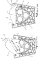
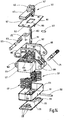
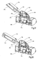
- the Fig. 1 and 2 show a corresponding prior art device for fixing and / or guiding cables or cable bundles a holding body 1 in a single representation without associated support structure.
- the holding body 1 has a trough-like recess 3 as a storage and implementation for strand elements, which tapers like a V-shape at the bottom, wherein in the recess 3, a bundle of three cables 5 is inserted from an upper opening 7 ago ,
- the Fig. 1 shows the opened state of the holding body 1, wherein a cover 9 is pivoted into a position releasing the opening 7.
- the Fig. 1 shows the opened state of the holding body 1, wherein a cover 9 is pivoted into a position releasing the opening 7.
- the cover 9 for applying a holding force on inserted cable 5 a pressing member 17, which is for a clamping movement relative to the main part of the cover 9 according to the prior art by a befindliches inside the cover 9, in Fig. 1 and 2 invisible spring package is biased. It shows Fig. 1 the over the available clamping range fully extended position of the pressing member 7, while Fig. 2 the holding force transmitting tensioned position of the pressing member 17 shows.
- the respective holding body 1 are formed by a frame which has a bent part made of sheet metal in the form of a U-profile body.
- This has as storage for strand elements bearing cheeks 19 and 21, which are formed by mutually parallel, planar profile legs of the U-profile, which are connected by a likewise planar, to the bearing cheeks 19, 21 perpendicular profile web 23 together.
- This serves as a mounting surface for the connection of the respective holding body 1 with the (not shown) support structure, for example by means of mounting holes 25 in the web 23.
- the storage in the bearing cheeks 19, 21 each have a recess 27th on, starting from a located at the free end of the bearing cheeks 19, 21 opening 29 starting the shape of a trough, whose width tapers towards the trough bottom 31 in the manner of a V-shape.
- the trough bottom 31 region of the edge of the recesses 27 contact surfaces 33 and 35 for inserted strand elements, of which in the Fig. 7 to 9 two cables 5 are visible.
- the recesses 27 extended in stages, with mutually parallel and vertically extending in the direction of the profile web 23 step surfaces 37 and 39 are formed.
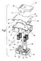
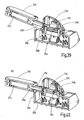
- the cover 9 whose items in Fig. 4 are shown in exploded exploded view, a main part 47 and a pressing member 49 which is movable relative to the main part 47 for a lifting movement over a clamping range.
- the pressing member 49 is biased in the manner mentioned in the relevant prior art by means of a package of four compression springs 51.
- the Fig. 5 shows the pressing member 49 in the fully extended clamping position, while in Fig. 6 the pressing member 49 is retracted against the action of the compression springs 51 and locked in this position.
- the main part 47 has the shape of a generally rectangular shell part, which is open in the direction of the pressing member 49.
- the pressing member 49 also has a main portion 47 adapted shell shape, wherein the shell bottom outside the pusher 53 forms, which exerts the retaining force on strand elements with projecting ribs 55.
- the shell of the pressing member 49 is guided on the inner shell walls of the main part 47 for lifting or clamping movements and forms together with the shell of the main part 47, the spring housing for sitting in the four corner areas on pin 57 compression springs 51.
- Main part 47 and pressing member 49 are respectively formed integrally, for example by injection molding preferably made of a thermoplastic material.
- the pressing member 49 has on its long sides on opposite projections 59, which extend perpendicularly from the bottom 53 forming the pusher surface.
- the lugs 59 form a guide body for the lifting and clamping movements of the pressing member 49 as well as part of the locking device.
- the lugs 59 are guided in guide tracks 61, which are formed on the long sides of the main part 47, which extends in mounted on the storage of the holding body 1 position in the axial direction of the strand elements from bearing cheek 19 to bearing che 21.
- the projections 59 extend beyond the upper side 63 of the main part 47, on which a flat cover plate 65 is made of sheet metal, which is clipped by means of bent tabs 67 located on the front sides of the main part 47 noses 68.
- Main parts of the locking device are in addition to the lugs 59 an eccentric 69 with an eccentric shaft 71.
- the eccentric shaft 71 of the eccentric 69 which is movable between the lugs 59, in the lugs 59 each have a slot 73 is formed. This runs in the direction of the lifting movement of the pressing member 49 over a distance corresponding to the full stroke length or the clamping range of the pressing member 49.
- the eccentric shaft 71 Under the action of the spring bias is the eccentric shaft 71, which engages with their ends in the slots 73, at the upper end of the slots 73 at. If the means of an integrally formed hand lever 75 rotatable, on the cover plate 65 supporting eccentric 69 in the in Fig. 3 .
- Fig. 7 to 10 illustrate the operation of the device according to the invention, wherein Fig. 7 shows the beginning of a mounting operation of the cover 9 for closing the opening 29 of the holding body 1, in which two strand elements in the form of cables 5 are inserted.
- the cover plate 65 of the cover 9 in the corner regions laterally projecting retaining wings 77 on.
- this is, starting from the in Fig. 7 shown position, offset in the axial direction of the cable 5, to the bearing cheeks 19, 21, inserted through the opening 29 between the bearing cheeks 19, 21 until the wings 77 are aligned with the recesses 41 of the bearing cheeks 19, 21.
- the wings 77 are, as most clearly from the Fig. 4 . 7 and 8th is to be seen, stepped and dimensioned in their length so that the outer step can pass through the lower recess 41 of the bearing cheeks 19, 21, but not through the upper recess 43. In with inserted strand elements supported Andrückteil 49 and thereby raised by the spring force main body 47 is therefore the most projecting step of the wings 77, above the bottom of the recesses 43 above, on the outer sides of the bearing cheeks 19, 21 to axially secure the cover 9.
- the procedure is such that the pressing member 49 is locked, so that the cover 9 is moved downward without any effort to align the wings 77 on the recesses 41.
- the axial displacement can take place until, after the passage of the wings 77 through the recesses 41, the covering device 9 is free for removal.
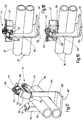
- the Fig. 11 shows an embodiment of the device according to the invention, in which the frame formed by a U-profile for several interconnected holding body, in the example shown for six holding body 1, is extended to a profile strip 81.
- the profile legs connected by the profile web 23 form the bearing-forming recesses 27, which are similarly shaped, as described above.
- a holding body 101 shown by a further embodiment.
- a corresponding number of holding bodies 101 may be provided and attached to the relevant support structure, such as a tower segment.
- the holding bodies 101 may be arranged next to each other in a straight sequence according to the type and shape of the attachment region on the support structure or in an arcuate course.
- the holding bodies 101 are formed by a bent part, which is bent from a rectangular sheet steel plate such that a first plate part 103 is formed, from which a shorter, second plate part 105 is bent at right angles.
- the second plate member 105 forms a flat mounting surface 107 for connection to the respective support structure, for example by screwing means not shown screw holes in the second plate member 105.
- the first plate member 103 forms a strand receiving space in the form of a U-shaped recess 109 for einer strand elements on the the second plate portion 105 opposite upper end has an insertion opening 111 which is bounded by opening edges 113 and 115.
- the bent sheet metal part can be extended to a number of holding body forming angle rail, in which the recesses 109 are formed in the first plate member 103 forming profile leg successively.
- the covering device 117 is in a position closing the opening 111 of the depression 109 (FIG. Fig. 12 ) or in an opening 111 releasing the open position ( Fig. 13 ).
- one of the covering device 117 associated locking device is in each case in its locking position.
- the details of the cover 117 and its locking device are in the Fig. 14 to 16 shown in more detail.
- the cover device is articulated for a pivoting movement by means of a pivot bearing 119 on the opening edge 115 of the plate part 103 of the holding body 101.
- a releasable latch assembly 121 which has a locking bolt 123, which is suitable for movement between a latch position, in the he with a latch hook 125 at the opening edge 113 is in positive engagement, and one of them withdrawn unlocking position is adjustable in position.
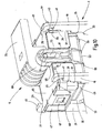
- Fig. 14 to 16 show, the cover 117 as a main part of a shell member 127 which is rectangular and open in the direction of a pressing member which transmits the holding force to be fixed to strand elements.
- This pressing member is formed by a second shell portion 129 which is adapted in shape to the first shell portion 127 and is telescopically movable in this, so that it, as the comparison of FIGS. 15 and 16 shows, a lifting movement between ejected clamping positions or a retracted position can perform in Fig. 15 is shown and in which the pressing part forming the second shell part 129 is securable by means of a locking device.
- the bottom 131 of the second shell part 129 forms the pusher, which cooperates via a voltage applied to the outside of the bottom 131, plate-shaped protective backing 133 with the strand elements to be fixed.
- the protective backing 133 has an outer contouring with projecting nubs 135.
- First shell part 127, second shell part 129 and protective backing 133 are injection-molded plastic parts.
- a spring assembly of six helical compression springs 137 one of which is arranged in each corner of the rectangular shape and one on the longitudinal center line of the rectangular shape, wherein the compression springs 137 are positioned on pins 139 projecting from the protective base 133 and from the inside of the first shell part 127.
- the locking device by means of which the pressing part forming the second shell part 129 against the action of the spring assembly in the inter alia in Fig. 15 shown, retracted position is securable, has an eccentric 141 which is manually rotatable by means of a hand lever 431.
- the eccentric 141 is formed together with the hand lever 143 by a one-piece plastic part, which consists of two circular discs 145 and 147th formed cylinder part, from which the hand lever 143 protruding extends.
- the circular disks 145, 147 are arranged at a distance from each other.
- a crank pin 149 extends, which is positioned at a location radially offset to the cylinder axis and thereby performs a stroke movement upon rotation of the circular disks 145, 147.
- a connecting rod 151 is provided which engages in the intermediate space between the circular discs 145, 147 and a slot 153, in which the crank pin 149 engages.
- the second shell part 129 facing the end of the connecting rod 151 is hinged to a hinge pin 150 on a bearing block 155 which is integrally formed on the bottom part 131 of the second shell part 129.
- the Fig. 16 shows the eccentric 141 in a release position of the pressing member corresponding rotational position in which the crank pin 149 is below the top 157 of the formed by the first shell portion 127 and the pressure lever 143 on the in Fig. 16 Left side located part of the top 157 rests.
- the pressing member forming the second shell part 129 is locked in the retracted position against the spring force by the compression springs 137.
- FIGS. 15 and 16 is at the top 157 of the main part forming the first shell portion 127 .
- a circular arc arched trough 159 is formed, which forms a kind of bearing seat during the rotation of the circular disks 145, 147.
- a cover plate 161 made of sheet metal, in the central region, as shown Fig. 14 can be seen, a rectangular recess 163 is recessed, which surrounds the trough 159.
- the longitudinal side edges 165 and 167 of the recess 163 form a lateral guide for the circular disks 145, 147 engaging in the recess 159, so that the eccentric 141 is secured in a defined position on the upper side 157 in conjunction with the pivot bearing formed by the recess 159.
- arms 169 are integrally formed on two opposite sides of the first shell portion 127, between which a engagement of the end portion of the first plate portion 103 of the holding body 101 enabling space is. This in FIGS. 12 and 13 on the right-most pair of arms 169 is by means of a pivot bearing 119 forming the pivot pin 171 ( Fig. 14 ) is hinged next to the opening edge 115 on the first plate part 103.
- the latch assembly 121 associated pair of arms 169 has a slot 173 in which a latch bolt 173 of the latch assembly 121 between a latch position in which it is latched to the latch hook 125 at the opening edge 113, and a retracted latch position is movable a locking spring biasing the locking bolt 123 into the locking position 175 is provided.
- Fig. 14 shows a fixing part 177, which is fixed to the first shell portion 127 below the cover plate 161, and at the other end a tab 179, which includes the central region of the locking bolt 123.
- the spring 175 forms an actuating device, which on the one hand generates the bias of the locking bolt 123, but on the other hand is accessible between the arms 169 for manual operation, such as Fig. 12 shows, and thereby the retraction of the locking bolt 123 allows in the unlocked position.
- the Fig. 14 shows that the arms 169 are laterally edged and reinforced by sheet metal parts 185, which are connected to each other via webs 187 extending in grooves 189 in the top 157 of the first shell part 127.
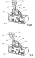
- the 17 to 19 illustrate the sequence of the fixing process for two cables 181.
- the Fig. 17 shows the cover 117 in the pivoted in the open position position, wherein the pressing member is locked in the retracted position.
- the cover 119 is already in the insertion opening 111 occluding position, wherein the pressing member is still locked, so that, since no spring force on the pressing member is effective, the pivoting is done in the closed position without effort.
- the Fig. 19 Finally, shows the final state in which the pressing member is released after unlocking the locking device for the clamping movement and exerts the holding force on the inserted cable 181.
- FIGS. 20 to 40 Another alternative of the locking device 200 of a cover device 202 according to the invention is in the FIGS. 20 to 40 shown.
- a cup-shaped main part 204 is provided, in which a likewise cup-shaped pressing member 206 is arranged to be telescopically displaceable.
- the main part 204 and the pressing part 206 are rectangular and four energy storage 208 are provided, which space the parts 204, 206 from each other.
- a bottom plate 210 is inserted, which has recesses for the energy storage 208 positioning pin 214. Furthermore protrude in the interior 216 of the pressing member 206 two parallel projections 218 with slots 220 in the direction of the main part 204 up and pass through the opening slots 222 of the main body 204th
- a recess 224 is provided on the upper side 226 of the main part 204.
- a strip-shaped bearing plate 228 is arranged in this recess 224.
- the main part 204 between the slots 222 has a thickened center part 230.
- a guide part 232 for an actuating lever 234 is provided on the upper side 226 of the main part 204.
- the guide member 232 is attached via two parallel bolts 236 on the central part 230 of the main part 204, wherein the bolts 236 pass through openings 238 in the bearing plate 228.
- the guide member 232 On its underside 240, the guide member 232 has laterally two recessed recesses 242 for bearing pin 244 described below.
- the guide part 232 On its upper side 246, the guide part 232 is provided with an asymmetrically shaped, rounded guide surface 248 for a latch part 250.
- the guide surface 248 runs along a left side surface 252 in the image plane and merges via a rounding 254 into a curved surface section 256 on the upper side 246 of the guide part 232 and then via a further rounding 258 into a right side surface 260 of the guide part 232.
- the curved central surface portion 256 has a maximum height H232 in the vicinity of the left side surface 252 and then extends with a cross-sectionally approximately circular portion-shaped curve 262 to the right side surface 260th
- the operating lever 234 is provided.
- the actuating lever 234 has two cheek parts 264 which, arranged in parallel, extend laterally of the guide part 232 and are pivotally attached there.
- the cheek parts 264 each have a thickened end portion 266 and provided in the longitudinal axis of the cheek portion 264 bore 268, in which the bearing pin 244 is fixed, which is supported on the bearing plate 228 and can slide on this and in the recess 242 of Guide member 232 is movable.
- Eccentric to the bore 268 for the bearing journal 244 of the respective cheek part 264 is in the end part 266 another Bore 270 is provided, which is located in the axial direction of the cheek part 264 between the bore 268 for the bearing pin 244 and an actuating part 272.
- a lifting pin 274 is fixed, which engages in the slot 220 of the adjacent projection 218 of the pressing member 206 to lift the pressing member 206 against the action of the energy storage 208 and to lock in the raised position AS.
- the actuating part 272 of the actuating lever 234 has two shell parts 276, 278, which are screwed together by bolts 280. Between the shell parts 276, 278 and the cheek parts 264, the latch part 250 is provided in the center of the operating lever 234.
- the latch member 250 is slidably disposed in the longitudinal direction LR of the actuating lever 234 and is acted upon by a further energy storage 282, in particular a gas spring or a helical compression spring which is arranged in the actuating part 272 in the direction of the guide surface 248 of the guide member 232.
- the latch member 252 is piston-shaped and preferably provided with a blind hole 284 for receiving and guiding the further energy storage 282.
- the latch member 250 is guided along the guide surface 248 of the guide member 232. In this case, it is displaced by the guide surface 248 in the operating part 272 against the action of the further energy storage 282. In this case, an additional force must be expended by an operator during pivoting of the actuating lever 234 for a slide-in movement.
- the latch member 250 When the operating lever 234 is pivoted from the unlocked position ES to the locking position VS, the latch member 250 is first displaced along the right side surface 260 of the guide member 232, the latch member 250 being slightly slid into the operating member 272. In this way, a resistance must be overcome to move the operating lever 234 from the unlocked position ES. If this resistance is overcome, the latch member 250 is displaced along the arcuate guide surface 248 of the guide member 232. In this pivoting region, the latch member 250 is held in position relative to the actuating member 272 or slightly shifted with increasing pivot angle in the operating part 272, so that in this pivoting range of the pivoting movement of the actuating lever 234 either no force or only a very small increasing force by the latch member 250th is opposed.
- the cover 202 also in this embodiment, a locking device 200, by means of which the pressing member 206 against the action of an energy storage 208 against movement into the clamping position selectively securable (locking position VS) or for a clamping movement (in the unlocked position ES) is releasable.
Landscapes
- Engineering & Computer Science (AREA)
- General Engineering & Computer Science (AREA)
- Mechanical Engineering (AREA)
- Architecture (AREA)
- Structural Engineering (AREA)
- Civil Engineering (AREA)
- Life Sciences & Earth Sciences (AREA)
- Combustion & Propulsion (AREA)
- Chemical & Material Sciences (AREA)
- Sustainable Energy (AREA)
- Sustainable Development (AREA)
- Clamps And Clips (AREA)
- Installation Of Indoor Wiring (AREA)
- Wind Motors (AREA)
- Supports For Pipes And Cables (AREA)
Claims (20)
- Dispositif d'immobilisation et/ou de guidage d'éléments filiformes, notamment de câbles (5 ; 181) ou de faisceaux de câble dans des éoliennes, comprenant au moins un corps (1 ; 101) de retenue pouvant, pour former un système de fixation modulaire, se combiner à une structure de support et ayant un espace (9, 109) de réception comme logement d'au moins un élément filiforme, qui peut y être inséré par une ouverture (29 ; 111) se trouvant sur son côté extérieur, comprenant un dispositif (9 ; 117 ; 202) de recouvrement, l'ouverture (29 ; 111) pouvant être fermée par le dispositif (9 ; 117 ; 202) de recouvrement, qui a une partie (47 ; 127 ; 204) principale, un accumulateur (51 ; 137 ; 208) d'énergie et une partie (17 ; 129 ; 206) d'application d'une pression, qui, au moyen de l'accumulateur (51 ; 137 ; 208) d'énergie, est mobile par rapport à la partie (47 ; 127 ; 204) principale pour venir dans une position de serrage, afin, lorsque le dispositif (9 ; 117 ; 202) de recouvrement ferme l'ouverture (29 ; 111), d'appliquer, dans une plage de serrage, une force de retenue à des éléments filiformes se trouvant dans l'espace (9 ; 109) de réception, caractérisé en ce que le dispositif (9 ; 117 ; 202) de recouvrement a un dispositif (69 ; 141 ; 200) de verrouillage, au moyen duquel la partie (17 ; 129 ; 206) d'application d'une pression peut, au choix, être empêchée d'effectuer un déplacement vers la position de serrage ou être libre d'effectuer un déplacement de serrage.
- Dispositif suivant la revendication 1, caractérisé en ce que la partie (17 ; 129 ; 206) d'application d'une pression est, par au moins un ressort (51 ; 137 ; 208) de compression servant d'accumulateur d'énergie, qui s'appuie sur la partie (47 ; 127 ; 204) principale pouvant être mise sur le corps (1 ; 101) de retenue du dispositif (9 ; 117 ; 202) de recouvrement, précontrainte pour le déplacement s'effectuant par rapport à la partie (47 ; 127 ; 204) principale, vers la position de serrage.
- Dispositif suivant la revendication 1 ou 2, caractérisé en ce que la partie (47 ; 127 ; 204) principale du dispositif (9 ; 117 ; 202) de recouvrement a une partie (47 ; 127) de cuvette ouverte en direction de la partie (17 ; 129 ; 206) d'application d'une pression et la partie (17 ; 129 ; 206) d'application d'une pression est constituée sous la forme d'une deuxième partie (49 ; 129) de cuvette, qui est mobile télescopiquement dans la première partie (47 ; 127) de cuvette et qui forme, par sa surface de fond, le poussoir (53 ; 131) appliquant la force de retenue aux éléments filiformes.
- Dispositif suivant l'une des revendications précédentes, caractérisé en ce que le logement a deux flasques (19, 21), qui sont à distance dans la direction axiale des éléments filiformes et qui, dans, respectivement, un évidement (27) de type en cuvette partant de l'ouverture (29) du côté extérieur, forment les surfaces (33, 35) de contact pour des éléments filiformes.
- Dispositif suivant la revendication 4, caractérisé en ce que le corps (1) de retenue a un bâti sous la forme d'un profilé en U, dans lequel les flasques (19, 21) sont formés par des branches du profilé s'étendant parallèlement entre elles et reliées entre elles par une âme (23) formant une surface d'application pour la liaison avec la structure de support.
- Dispositif suivant la revendication 4 ou 5, caractérisé en ce que la largeur des évidements (27) des flasques (19, 21), à partir des surfaces (33, 35) de contact au fond (31) des évidements (27), s'élargit par degré en direction de l'ouverture (29), les degrés inférieurs formant des surfaces (35) de guidage du déplacement de serrage de la partie (49) d'application d'une pression et des degrés, venant ensuite en direction de l'ouverture (29), formant des surfaces (37) d'assise du dispositif (9) de recouvrement mis sur le logement.
- Dispositif suivant l'une des revendications 4 à 6, caractérisé en ce que la partie (47) principale du dispositif (9) de recouvrement a une partie de cuvette, qui est ouverte en direction de la partie (49) d'application d'une pression, qui s'étend, dans la position mise sur le logement, dans la direction axiale des éléments filiformes du flasque (19) au flasque (21) et qui forme, sur les côtés s'étendant entre ces flasques, des glissières (61) dans lesquelles- sont guidés des appendices (59) de la partie (49) d'application d'une pression pour ses déplacements s'effectuant par rapport à la partie (47) principale.
- Dispositif suivant la revendication 7, caractérisé en ce que les appendices (59 ; 218) de la partie (49 ; 206) d'application d'une pression forment, avec des régions d'extrémité dépassant de la partie (47 ; 204) principale, des éléments fonctionnels du dispositif (59 ; 69 ; 71 ; 200) de verrouillage.
- Dispositif suivant la revendication 8, caractérisé en ce que le dispositif de verrouillage a un excentrique (69), qui peut être tourné manuellement et qui s'appuie sur le côté (63) supérieur de la partie (47) principale, de sorte que l'arbre (71) de l'excentrique formant l'axe de l'excentrique exécute, lors de la rotation, une ascension par rapport à a partie (47) principale et en ce que l'arbre (71) de l'excentrique pénètre dans une boutonnière (73) des appendices (59) de la partie (49) d'application d'une pression, de manière à ce que, dans la position de verrouillage de l'excentrique (69), la partie (49) d'application d'une pression soit tirée à l'encontre de l'effet de ressort de précontrainte sur la partie (47) principale et de manière à ce qu'elle soit libérée pour le déplacement de serrage dans la position de libération de l'excentrique (69).
- Dispositif suivant la revendication 6 à 9, caractérisé en ce que les flasques (19, 21) ont, à l'ouverture (29) des évidements (27), des parties (45) de crochet faisant saillie l'une vers l'autre et suivent des cavités (41, 43) formées dans les flasques (19, 21), que, lorsque le dispositif de recouvrement est mis, peuvent traverser des ailes (77) de retenue disposées en porte à faux latéralement sur la partie (47) principale et qui, en la position où le dispositif (9) de recouvrement est mis, sont accrochées par les parties (45) de crochets.
- Dispositif suivant la revendication 9 ou 10, caractérisé en ce que les ailes (77) de retenue sont prévues aux extrémités d'un plateau (65) de recouvrement de la partie (47) principale sur lequel l'excentrique (69) du dispositif (59,69, 71) de verrouillage s'appuie.
- Dispositif suivant l'une des revendications 7 à 11, caractérisé en ce qu'aux deux extrémités, associées aux flasques (19, 21), des côtés, ayant les glissières (61), de la partie (47) principale sont prévus des becs (79) d'encliquetage en saillie et cédant élastiquement, qui, en la position, dirigée sur le logement, du dispositif (9) de recouvrement, s'encliquètent sur les côtés intérieurs des flasques (19, 21).
- Dispositif suivant l'une des revendications 1 à 3, caractérisé en ce que le dispositif de verrouillage a un excentrique (141), qui peut être tourné manuellement et qui s'appuie sur le côté (157) supérieur de la partie (127) principale, de manière à ce qu'un tourillon (149) de manivelle associé, formant l'axe de l'excentrique, exécute, lors de la rotation, une ascension par rapport à la partie 127) principale et de manière à ce que le tourillon (149) de manivelle soit couplé à la partie (129) d'application d'une pression par une bielle (151), en de manière à ce que, dans la position de verrouillage de l'excentrique (141), la partie (129) d'application d'une pression soit tirée, à l'encontre de l'effet de ressort de précontrainte sur la partie (127) principale et, dans la position de libération l'excentrique (41) soit libre d'effectuer le déplacement de serrage.
- Dispositif suivant la revendication 13, caractérisé en ce que l'excentrique (141) a une partie (145, 147) cylindrique, qui peut être tournée manuellement au moyen d'un levier (143) à main en porte à faux de celle-ci, qui s'appuie sur le côté (157) supérieur de la partie (127) principale et qui a le tourillon (149) de manivelle se trouvant à distance de l'axe du cylindre.
- Dispositif suivant la revendication 14, caractérisé en ce que la partie cylindrique est formée de deux disques (145, 147) circulaires se trouvant à distance l'un de l'autre et entre lesquels est disposé le tourillon (149) de manivelle pour la bielle (151) pénétrant entre les disques (145, 147) circulaires.
- Dispositif suivant la revendication 15, caractérisé en ce que, du côté (157) supérieur de la partie (127) principale, est formé, comme logement de la partie (145, 147) cylindrique, une cuvette (159), dans laquelle cette partie pénètre en passant par un évidement (163) ménagé dans une plaque (161)de recouvrement s'appliquant au côté (157) supérieur de la partie (127) principale, l'évidement (163) étant délimité par des bords (165) d'ouverture opposés, qui s'étendent dans les plans des disques (145, 147) circulaires pénétrant dans l'évidement (163).
- Dispositif suivant l'une des revendications 13 à 16, caractérisé en ce que le corps (101) de retenu a un espace de réception sous la forme d'une cavité (109) en forme de U ou de V, ayant une ouverture (111) d'introduction à bords (113, 115) opposés mutuellement, sur l'un (115) desquels le dispositif (117) de recouvrement est monté pivotant, de manière à pouvoir se déplacer entre une position d'ouverture et une position fermant l'ouverture (111) d'introduction et en ce qu'il est prévu, sur le dispositif (117) de recouvrement, un agencement (121) de verrou, au moyen duquel il peut être verrouillé avec l'autre bord (113) de l'ouverture, de manière amovible, dans la position de fermeture.
- Dispositif suivant la revendication 17, caractérisé en ce que le corps (101) de retenue est formé d'une partie de tôle pliée ayant une première partie (103) de plaque plane, qui a la cavité (109) de l'espace de réception, et une deuxième partie (105) de plaque coudée par rapport à celle-ci, qui forme une surface d'application opposée à l'ouverture (111) d'insertion, pour la liaison avec une structure de support.
- Dispositif suivant la revendication 18, caractérisé en ce que la partie (127) principale du dispositif (117) de recouvrement a, pour la liaison avec chaque bord (113, 115) de l'ouverture (111) d'insertion de la première partie (103) de plaque, respectivement, une paire de bras (169) en porte à faux en sens opposé de la partie (127) principale, entre lesquels est formé un espace intermédiaire permettant la pénétration de cette partie (103) de plaque.
- Dispositif suivant la revendication 17 à 19, caractérisé en ce que les bras (169) de la paire de bras, associée à l'agencement (121) de verrou, ont chacun une boutonnière (173), dans laquelle un axe (171) de verrouillage peut se déplacer entre une position de verrouillage, dans laquelle il est encliqueté par un crochet (125) de verrouillage au bord (113) de l'ouverture, et une position de déverrouillage en retrait et en ce qu'il y a un ressort (75) d'actionnement, qui précontraint l'axe (171) de verrouillage dans la position de verrouillage et qui, pour libérer l'agencement (121) de verrou, peut être déplacé manuellement pour venir dans une position retirant l'axe (171) du verrou.
Applications Claiming Priority (2)
| Application Number | Priority Date | Filing Date | Title |
|---|---|---|---|
| DE102015013791.3A DE102015013791A1 (de) | 2015-10-22 | 2015-10-22 | Einrichtung zur Fixierung und/oder Führung von strangförmigen Elementen |
| PCT/EP2016/001730 WO2017067658A1 (fr) | 2015-10-22 | 2016-10-19 | Dispositif de fixation et/ou de guidage d'éléments en forme de faisceaux |
Publications (2)
| Publication Number | Publication Date |
|---|---|
| EP3365953A1 EP3365953A1 (fr) | 2018-08-29 |
| EP3365953B1 true EP3365953B1 (fr) | 2019-06-19 |
Family
ID=57206197
Family Applications (1)
| Application Number | Title | Priority Date | Filing Date |
|---|---|---|---|
| EP16787326.4A Active EP3365953B1 (fr) | 2015-10-22 | 2016-10-19 | Dispositif de fixation et/ou de guidage d'éléments en forme de faisceaux |
Country Status (8)
| Country | Link |
|---|---|
| US (1) | US10626854B2 (fr) |
| EP (1) | EP3365953B1 (fr) |
| JP (1) | JP6770065B2 (fr) |
| KR (1) | KR102221202B1 (fr) |
| CN (1) | CN108028524B (fr) |
| DE (1) | DE102015013791A1 (fr) |
| ES (1) | ES2745992T3 (fr) |
| WO (1) | WO2017067658A1 (fr) |
Families Citing this family (8)
| Publication number | Priority date | Publication date | Assignee | Title |
|---|---|---|---|---|
| DE102016015226A1 (de) * | 2016-12-21 | 2018-06-21 | Hydac Accessories Gmbh | Festlegevorrichtung |
| DE102019000055A1 (de) * | 2019-01-08 | 2020-07-09 | Senvion Gmbh | Windenergieanlage und Verfahren zurn Betreiben einer Windenergieanlage |
| CN109707603B (zh) * | 2019-03-18 | 2024-03-22 | 保定申辰泵业有限公司 | 一种开合与装卡软管的联动机构、蠕动泵泵头及蠕动泵 |
| DE102019126475B4 (de) * | 2019-10-01 | 2024-05-16 | Lisa Dräxlmaier GmbH | Kabelaufnahmevorrichtung |
| US11651869B2 (en) | 2020-06-29 | 2023-05-16 | Panduit Corp. | Thermal expansion slide with cable clamp |
| US11985793B2 (en) * | 2021-01-22 | 2024-05-14 | Dell Products L.P. | Cable sealing apparatus and methods |
| BE1029269B1 (de) * | 2021-04-01 | 2022-11-04 | Phoenix Contact Gmbh & Co | Klemmvorrichtung |
| CN117345740A (zh) * | 2022-06-27 | 2024-01-05 | 索斯科锁定技术(上海)有限公司 | 锁定装置 |
Family Cites Families (20)
| Publication number | Priority date | Publication date | Assignee | Title |
|---|---|---|---|---|
| DE821C (de) * | 1877-07-02 | F. quatram in Berlin | Expansionssteuerung für Dampfmaschinen | |
| DE695125C (de) | 1937-07-16 | 1940-08-17 | E H Dr Phil H C Ernst Heinkel | Kabelhalter, insbesondere fuer Luftfahrzeuge |
| US2650948A (en) * | 1951-04-13 | 1953-09-01 | Boeing Co | Wire holder |
| JPH07183670A (ja) | 1993-12-22 | 1995-07-21 | Nikko Kogyo Kk | 電線固定具 |
| US20080185183A1 (en) * | 2007-02-07 | 2008-08-07 | Chien-Chung Chen | Resonance-coordinating device for audio and video |
| US8057139B2 (en) * | 2009-01-21 | 2011-11-15 | Federal Signal Corporation | Tube restraint and methods |
| DE102010032686A1 (de) * | 2010-07-29 | 2012-02-02 | Hydac Accessories Gmbh | Befestigungssystem für Leitungen, insbesondere für Kabel bei Windkraftanlagen |
| US8664544B2 (en) * | 2010-07-29 | 2014-03-04 | Hydac Accessories Gmbh | Attachment system for cables, in particular for wind turbines |
| DE102010032687A1 (de) * | 2010-07-29 | 2012-02-02 | Hydac Accessories Gmbh | Befestigungssystem für Kabel, insbesondere bei Windkraftanlagen |
| DE102011012391A1 (de) * | 2011-02-25 | 2012-08-30 | Hydac Accessories Gmbh | Befestigungssystem für Kabel, insbesondere bei Windkraftanlagen |
| DE102012001407B4 (de) * | 2012-01-25 | 2015-05-28 | Hydac Accessories Gmbh | Befestigungssystem für strangförmige Funktionselemente bei Windkraftanlagen, nebst Einsatzelement |
| DE102012001408A1 (de) * | 2012-01-25 | 2013-07-25 | Hydac Accessories Gmbh | Befestigungssystem |
| DE102012001409A1 (de) * | 2012-01-25 | 2013-07-25 | Hydac Accessories Gmbh | Befestigungssystem für strangförmige Funktionselemente, insbesondere bei Windkraftanlagen |
| DE102012007416B4 (de) * | 2012-04-16 | 2016-08-18 | Hydac Accessoires GmbH | Befestigungssystem |
| DE102012013465A1 (de) * | 2012-07-09 | 2014-05-08 | Eppendorf Ag | Haltevorrichtung |
| DE102012017463A1 (de) | 2012-09-04 | 2014-03-06 | Hydac Accessories Gmbh | Befestigungssystem für Strangelemente, insbesondere bei Windkraftanlagen |
| DE102012019490A1 (de) * | 2012-10-04 | 2014-04-10 | Hydac Accessories Gmbh | System zur Führung und Lagesicherung von Strangelementen |
| DE102013010821A1 (de) | 2013-06-28 | 2014-12-31 | Hydac Accessories Gmbh | Einrichtung zur Fixierung und/oder Führung von strangförmigen Elementen |
| DE102014004931A1 (de) * | 2014-04-05 | 2015-10-08 | Hydac Accessoires GmbH | Abstandshalteeinrichtung |
| DE102014116468B4 (de) * | 2014-11-11 | 2016-08-25 | Lisa Dräxlmaier GmbH | Befestigungselement und Kabelschacht |
-
2015
- 2015-10-22 DE DE102015013791.3A patent/DE102015013791A1/de not_active Withdrawn
-
2016
- 2016-10-19 WO PCT/EP2016/001730 patent/WO2017067658A1/fr active Application Filing
- 2016-10-19 US US15/759,548 patent/US10626854B2/en active Active
- 2016-10-19 ES ES16787326T patent/ES2745992T3/es active Active
- 2016-10-19 CN CN201680055035.2A patent/CN108028524B/zh active Active
- 2016-10-19 KR KR1020187011099A patent/KR102221202B1/ko active IP Right Grant
- 2016-10-19 JP JP2018515074A patent/JP6770065B2/ja active Active
- 2016-10-19 EP EP16787326.4A patent/EP3365953B1/fr active Active
Non-Patent Citations (1)
| Title |
|---|
| None * |
Also Published As
| Publication number | Publication date |
|---|---|
| CN108028524B (zh) | 2020-09-25 |
| US10626854B2 (en) | 2020-04-21 |
| ES2745992T3 (es) | 2020-03-04 |
| DE102015013791A1 (de) | 2017-04-27 |
| JP6770065B2 (ja) | 2020-10-14 |
| KR102221202B1 (ko) | 2021-03-04 |
| JP2019502339A (ja) | 2019-01-24 |
| WO2017067658A1 (fr) | 2017-04-27 |
| CN108028524A (zh) | 2018-05-11 |
| EP3365953A1 (fr) | 2018-08-29 |
| US20190154008A1 (en) | 2019-05-23 |
| KR20180079306A (ko) | 2018-07-10 |
Similar Documents
| Publication | Publication Date | Title |
|---|---|---|
| EP3365953B1 (fr) | Dispositif de fixation et/ou de guidage d'éléments en forme de faisceaux | |
| EP0238848B1 (fr) | Dispositif de fixation ayant une fermeture de serrage pour l'attachement amovible à des profils ayant des contre de pouilles | |
| EP2427401B1 (fr) | Elément de suspension d'un dispositif à câble pendant | |
| EP3020107B1 (fr) | Système de fixation et/ou de guidage d'éléments en forme de boudins | |
| DE102008037956B4 (de) | Betriebsmechanismus für ein bewegliches Verschlusselement | |
| EP1516402B1 (fr) | Attache de cable | |
| DE19936280A1 (de) | Türscharniersystem | |
| EP0504557A1 (fr) | Dispositif de tension et d'amarrage pour sangles d'amarrage | |
| EP2893236B1 (fr) | Système de fixation pour éléments allongés, en particulier pour installations éoliennes | |
| EP2636489B1 (fr) | Pince avec levier d'actionnement | |
| DE2632338C2 (de) | Gehäusehälften-Verschluß für mehrpolige elektrische Steckvorrichtungen | |
| WO2020089031A1 (fr) | Traversée de câble | |
| DE102010014054B4 (de) | Öffnungshilfe für Energieführungsketten | |
| DE102016124619A1 (de) | Mehrfach-Arretiervorrichtung für einen Arretierbeschlag für eine Zarge, Zarge und Schubkasten | |
| DE3601233C2 (fr) | ||
| DE3315335C2 (fr) | ||
| EP2578891B1 (fr) | Adapteur | |
| DE102015116612A1 (de) | Beschlag für eine Schiebetür und Verfahren zur Montage einer Schiebetür | |
| EP0196489A1 (fr) | Dispositif pour emboîter deux tuyaux | |
| DE202020102621U1 (de) | Halterahmen und Steckverbinder mit einem derartigen Halterahmen | |
| DE102015219124A1 (de) | Anbauteil für ein Fahrzeug | |
| DE202006004486U1 (de) | Befestigungseinheit mit einem Befestigungselement | |
| EP2317164B1 (fr) | Crochet, notamment pour dispositifs de sécurité | |
| DE102016015226A1 (de) | Festlegevorrichtung | |
| EP3335592B1 (fr) | Dispositif d'arrêt pour une ferrure d'arrêt pour un châssis et châssis pourvu de ferrure d'arrêt |
Legal Events
| Date | Code | Title | Description |
|---|---|---|---|
| STAA | Information on the status of an ep patent application or granted ep patent |
Free format text: STATUS: UNKNOWN |
|
| STAA | Information on the status of an ep patent application or granted ep patent |
Free format text: STATUS: THE INTERNATIONAL PUBLICATION HAS BEEN MADE |
|
| PUAI | Public reference made under article 153(3) epc to a published international application that has entered the european phase |
Free format text: ORIGINAL CODE: 0009012 |
|
| STAA | Information on the status of an ep patent application or granted ep patent |
Free format text: STATUS: REQUEST FOR EXAMINATION WAS MADE |
|
| 17P | Request for examination filed |
Effective date: 20180522 |
|
| AK | Designated contracting states |
Kind code of ref document: A1 Designated state(s): AL AT BE BG CH CY CZ DE DK EE ES FI FR GB GR HR HU IE IS IT LI LT LU LV MC MK MT NL NO PL PT RO RS SE SI SK SM TR |
|
| AX | Request for extension of the european patent |
Extension state: BA ME |
|
| DAV | Request for validation of the european patent (deleted) | ||
| DAX | Request for extension of the european patent (deleted) | ||
| GRAP | Despatch of communication of intention to grant a patent |
Free format text: ORIGINAL CODE: EPIDOSNIGR1 |
|
| STAA | Information on the status of an ep patent application or granted ep patent |
Free format text: STATUS: GRANT OF PATENT IS INTENDED |
|
| INTG | Intention to grant announced |
Effective date: 20190313 |
|
| GRAS | Grant fee paid |
Free format text: ORIGINAL CODE: EPIDOSNIGR3 |
|
| GRAA | (expected) grant |
Free format text: ORIGINAL CODE: 0009210 |
|
| STAA | Information on the status of an ep patent application or granted ep patent |
Free format text: STATUS: THE PATENT HAS BEEN GRANTED |
|
| AK | Designated contracting states |
Kind code of ref document: B1 Designated state(s): AL AT BE BG CH CY CZ DE DK EE ES FI FR GB GR HR HU IE IS IT LI LT LU LV MC MK MT NL NO PL PT RO RS SE SI SK SM TR |
|
| REG | Reference to a national code |
Ref country code: GB Ref legal event code: FG4D Free format text: NOT ENGLISH |
|
| REG | Reference to a national code |
Ref country code: CH Ref legal event code: EP |
|
| REG | Reference to a national code |
Ref country code: IE Ref legal event code: FG4D Free format text: LANGUAGE OF EP DOCUMENT: GERMAN |
|
| REG | Reference to a national code |
Ref country code: DE Ref legal event code: R096 Ref document number: 502016005190 Country of ref document: DE |
|
| REG | Reference to a national code |
Ref country code: AT Ref legal event code: REF Ref document number: 1146704 Country of ref document: AT Kind code of ref document: T Effective date: 20190715 |
|
| REG | Reference to a national code |
Ref country code: NL Ref legal event code: MP Effective date: 20190619 |
|
| PG25 | Lapsed in a contracting state [announced via postgrant information from national office to epo] |
Ref country code: SE Free format text: LAPSE BECAUSE OF FAILURE TO SUBMIT A TRANSLATION OF THE DESCRIPTION OR TO PAY THE FEE WITHIN THE PRESCRIBED TIME-LIMIT Effective date: 20190619 Ref country code: HR Free format text: LAPSE BECAUSE OF FAILURE TO SUBMIT A TRANSLATION OF THE DESCRIPTION OR TO PAY THE FEE WITHIN THE PRESCRIBED TIME-LIMIT Effective date: 20190619 Ref country code: LT Free format text: LAPSE BECAUSE OF FAILURE TO SUBMIT A TRANSLATION OF THE DESCRIPTION OR TO PAY THE FEE WITHIN THE PRESCRIBED TIME-LIMIT Effective date: 20190619 Ref country code: AL Free format text: LAPSE BECAUSE OF FAILURE TO SUBMIT A TRANSLATION OF THE DESCRIPTION OR TO PAY THE FEE WITHIN THE PRESCRIBED TIME-LIMIT Effective date: 20190619 Ref country code: NO Free format text: LAPSE BECAUSE OF FAILURE TO SUBMIT A TRANSLATION OF THE DESCRIPTION OR TO PAY THE FEE WITHIN THE PRESCRIBED TIME-LIMIT Effective date: 20190919 Ref country code: FI Free format text: LAPSE BECAUSE OF FAILURE TO SUBMIT A TRANSLATION OF THE DESCRIPTION OR TO PAY THE FEE WITHIN THE PRESCRIBED TIME-LIMIT Effective date: 20190619 |
|
| REG | Reference to a national code |
Ref country code: LT Ref legal event code: MG4D |
|
| PG25 | Lapsed in a contracting state [announced via postgrant information from national office to epo] |
Ref country code: BG Free format text: LAPSE BECAUSE OF FAILURE TO SUBMIT A TRANSLATION OF THE DESCRIPTION OR TO PAY THE FEE WITHIN THE PRESCRIBED TIME-LIMIT Effective date: 20190919 Ref country code: LV Free format text: LAPSE BECAUSE OF FAILURE TO SUBMIT A TRANSLATION OF THE DESCRIPTION OR TO PAY THE FEE WITHIN THE PRESCRIBED TIME-LIMIT Effective date: 20190619 Ref country code: RS Free format text: LAPSE BECAUSE OF FAILURE TO SUBMIT A TRANSLATION OF THE DESCRIPTION OR TO PAY THE FEE WITHIN THE PRESCRIBED TIME-LIMIT Effective date: 20190619 Ref country code: GR Free format text: LAPSE BECAUSE OF FAILURE TO SUBMIT A TRANSLATION OF THE DESCRIPTION OR TO PAY THE FEE WITHIN THE PRESCRIBED TIME-LIMIT Effective date: 20190920 |
|
| PG25 | Lapsed in a contracting state [announced via postgrant information from national office to epo] |
Ref country code: NL Free format text: LAPSE BECAUSE OF FAILURE TO SUBMIT A TRANSLATION OF THE DESCRIPTION OR TO PAY THE FEE WITHIN THE PRESCRIBED TIME-LIMIT Effective date: 20190619 Ref country code: CZ Free format text: LAPSE BECAUSE OF FAILURE TO SUBMIT A TRANSLATION OF THE DESCRIPTION OR TO PAY THE FEE WITHIN THE PRESCRIBED TIME-LIMIT Effective date: 20190619 Ref country code: SK Free format text: LAPSE BECAUSE OF FAILURE TO SUBMIT A TRANSLATION OF THE DESCRIPTION OR TO PAY THE FEE WITHIN THE PRESCRIBED TIME-LIMIT Effective date: 20190619 Ref country code: RO Free format text: LAPSE BECAUSE OF FAILURE TO SUBMIT A TRANSLATION OF THE DESCRIPTION OR TO PAY THE FEE WITHIN THE PRESCRIBED TIME-LIMIT Effective date: 20190619 Ref country code: EE Free format text: LAPSE BECAUSE OF FAILURE TO SUBMIT A TRANSLATION OF THE DESCRIPTION OR TO PAY THE FEE WITHIN THE PRESCRIBED TIME-LIMIT Effective date: 20190619 Ref country code: PT Free format text: LAPSE BECAUSE OF FAILURE TO SUBMIT A TRANSLATION OF THE DESCRIPTION OR TO PAY THE FEE WITHIN THE PRESCRIBED TIME-LIMIT Effective date: 20191021 |
|
| PG25 | Lapsed in a contracting state [announced via postgrant information from national office to epo] |
Ref country code: IS Free format text: LAPSE BECAUSE OF FAILURE TO SUBMIT A TRANSLATION OF THE DESCRIPTION OR TO PAY THE FEE WITHIN THE PRESCRIBED TIME-LIMIT Effective date: 20191019 Ref country code: SM Free format text: LAPSE BECAUSE OF FAILURE TO SUBMIT A TRANSLATION OF THE DESCRIPTION OR TO PAY THE FEE WITHIN THE PRESCRIBED TIME-LIMIT Effective date: 20190619 Ref country code: IT Free format text: LAPSE BECAUSE OF FAILURE TO SUBMIT A TRANSLATION OF THE DESCRIPTION OR TO PAY THE FEE WITHIN THE PRESCRIBED TIME-LIMIT Effective date: 20190619 |
|
| REG | Reference to a national code |
Ref country code: ES Ref legal event code: FG2A Ref document number: 2745992 Country of ref document: ES Kind code of ref document: T3 Effective date: 20200304 |
|
| PG25 | Lapsed in a contracting state [announced via postgrant information from national office to epo] |
Ref country code: TR Free format text: LAPSE BECAUSE OF FAILURE TO SUBMIT A TRANSLATION OF THE DESCRIPTION OR TO PAY THE FEE WITHIN THE PRESCRIBED TIME-LIMIT Effective date: 20190619 |
|
| PG25 | Lapsed in a contracting state [announced via postgrant information from national office to epo] |
Ref country code: DK Free format text: LAPSE BECAUSE OF FAILURE TO SUBMIT A TRANSLATION OF THE DESCRIPTION OR TO PAY THE FEE WITHIN THE PRESCRIBED TIME-LIMIT Effective date: 20190619 Ref country code: PL Free format text: LAPSE BECAUSE OF FAILURE TO SUBMIT A TRANSLATION OF THE DESCRIPTION OR TO PAY THE FEE WITHIN THE PRESCRIBED TIME-LIMIT Effective date: 20190619 |
|
| PG25 | Lapsed in a contracting state [announced via postgrant information from national office to epo] |
Ref country code: IS Free format text: LAPSE BECAUSE OF FAILURE TO SUBMIT A TRANSLATION OF THE DESCRIPTION OR TO PAY THE FEE WITHIN THE PRESCRIBED TIME-LIMIT Effective date: 20200224 Ref country code: MC Free format text: LAPSE BECAUSE OF FAILURE TO SUBMIT A TRANSLATION OF THE DESCRIPTION OR TO PAY THE FEE WITHIN THE PRESCRIBED TIME-LIMIT Effective date: 20190619 |
|
| REG | Reference to a national code |
Ref country code: CH Ref legal event code: PL |
|
| REG | Reference to a national code |
Ref country code: DE Ref legal event code: R097 Ref document number: 502016005190 Country of ref document: DE |
|
| PLBE | No opposition filed within time limit |
Free format text: ORIGINAL CODE: 0009261 |
|
| STAA | Information on the status of an ep patent application or granted ep patent |
Free format text: STATUS: NO OPPOSITION FILED WITHIN TIME LIMIT |
|
| PG2D | Information on lapse in contracting state deleted |
Ref country code: IS |
|
| PG25 | Lapsed in a contracting state [announced via postgrant information from national office to epo] |
Ref country code: CH Free format text: LAPSE BECAUSE OF NON-PAYMENT OF DUE FEES Effective date: 20191031 Ref country code: LI Free format text: LAPSE BECAUSE OF NON-PAYMENT OF DUE FEES Effective date: 20191031 Ref country code: LU Free format text: LAPSE BECAUSE OF NON-PAYMENT OF DUE FEES Effective date: 20191019 |
|
| 26N | No opposition filed |
Effective date: 20200603 |
|
| REG | Reference to a national code |
Ref country code: BE Ref legal event code: MM Effective date: 20191031 |
|
| PG25 | Lapsed in a contracting state [announced via postgrant information from national office to epo] |
Ref country code: SI Free format text: LAPSE BECAUSE OF FAILURE TO SUBMIT A TRANSLATION OF THE DESCRIPTION OR TO PAY THE FEE WITHIN THE PRESCRIBED TIME-LIMIT Effective date: 20190619 Ref country code: BE Free format text: LAPSE BECAUSE OF NON-PAYMENT OF DUE FEES Effective date: 20191031 |
|
| PG25 | Lapsed in a contracting state [announced via postgrant information from national office to epo] |
Ref country code: IE Free format text: LAPSE BECAUSE OF NON-PAYMENT OF DUE FEES Effective date: 20191019 |
|
| PG25 | Lapsed in a contracting state [announced via postgrant information from national office to epo] |
Ref country code: CY Free format text: LAPSE BECAUSE OF FAILURE TO SUBMIT A TRANSLATION OF THE DESCRIPTION OR TO PAY THE FEE WITHIN THE PRESCRIBED TIME-LIMIT Effective date: 20190619 |
|
| GBPC | Gb: european patent ceased through non-payment of renewal fee |
Effective date: 20201019 |
|
| PG25 | Lapsed in a contracting state [announced via postgrant information from national office to epo] |
Ref country code: MT Free format text: LAPSE BECAUSE OF FAILURE TO SUBMIT A TRANSLATION OF THE DESCRIPTION OR TO PAY THE FEE WITHIN THE PRESCRIBED TIME-LIMIT Effective date: 20190619 Ref country code: HU Free format text: LAPSE BECAUSE OF FAILURE TO SUBMIT A TRANSLATION OF THE DESCRIPTION OR TO PAY THE FEE WITHIN THE PRESCRIBED TIME-LIMIT; INVALID AB INITIO Effective date: 20161019 |
|
| PG25 | Lapsed in a contracting state [announced via postgrant information from national office to epo] |
Ref country code: GB Free format text: LAPSE BECAUSE OF NON-PAYMENT OF DUE FEES Effective date: 20201019 |
|
| PG25 | Lapsed in a contracting state [announced via postgrant information from national office to epo] |
Ref country code: MK Free format text: LAPSE BECAUSE OF FAILURE TO SUBMIT A TRANSLATION OF THE DESCRIPTION OR TO PAY THE FEE WITHIN THE PRESCRIBED TIME-LIMIT Effective date: 20190619 |
|
| PGFP | Annual fee paid to national office [announced via postgrant information from national office to epo] |
Ref country code: FR Payment date: 20220902 Year of fee payment: 7 |
|
| REG | Reference to a national code |
Ref country code: AT Ref legal event code: MM01 Ref document number: 1146704 Country of ref document: AT Kind code of ref document: T Effective date: 20211019 |
|
| PG25 | Lapsed in a contracting state [announced via postgrant information from national office to epo] |
Ref country code: AT Free format text: LAPSE BECAUSE OF NON-PAYMENT OF DUE FEES Effective date: 20211019 |
|
| PGFP | Annual fee paid to national office [announced via postgrant information from national office to epo] |
Ref country code: ES Payment date: 20221104 Year of fee payment: 7 Ref country code: DE Payment date: 20221031 Year of fee payment: 7 |