JP6770065B2 - 索形状の部材を固定及び/又は案内する装置 - Google Patents
索形状の部材を固定及び/又は案内する装置 Download PDFInfo
- Publication number
- JP6770065B2 JP6770065B2 JP2018515074A JP2018515074A JP6770065B2 JP 6770065 B2 JP6770065 B2 JP 6770065B2 JP 2018515074 A JP2018515074 A JP 2018515074A JP 2018515074 A JP2018515074 A JP 2018515074A JP 6770065 B2 JP6770065 B2 JP 6770065B2
- Authority
- JP
- Japan
- Prior art keywords
- cover device
- bearing
- pressing portion
- main portion
- pressing
- Prior art date
- Legal status (The legal status is an assumption and is not a legal conclusion. Google has not performed a legal analysis and makes no representation as to the accuracy of the status listed.)
- Active
Links
- 238000003825 pressing Methods 0.000 claims description 91
- 238000003780 insertion Methods 0.000 claims description 15
- 230000037431 insertion Effects 0.000 claims description 15
- 230000006835 compression Effects 0.000 claims description 14
- 238000007906 compression Methods 0.000 claims description 14
- 230000008878 coupling Effects 0.000 claims description 8
- 238000010168 coupling process Methods 0.000 claims description 8
- 238000005859 coupling reaction Methods 0.000 claims description 8
- 238000000034 method Methods 0.000 claims description 8
- 238000004146 energy storage Methods 0.000 claims description 2
- 239000002184 metal Substances 0.000 description 5
- 230000001681 protective effect Effects 0.000 description 4
- 230000007704 transition Effects 0.000 description 4
- 229910000831 Steel Inorganic materials 0.000 description 3
- 239000004033 plastic Substances 0.000 description 3
- 239000010959 steel Substances 0.000 description 3
- 238000005452 bending Methods 0.000 description 2
- 238000013459 approach Methods 0.000 description 1
- 238000004891 communication Methods 0.000 description 1
- 230000000295 complement effect Effects 0.000 description 1
- 238000001746 injection moulding Methods 0.000 description 1
- 239000000463 material Substances 0.000 description 1
- 239000002991 molded plastic Substances 0.000 description 1
- 238000012544 monitoring process Methods 0.000 description 1
- 230000000717 retained effect Effects 0.000 description 1
- 239000000243 solution Substances 0.000 description 1
- 229920001169 thermoplastic Polymers 0.000 description 1
- 239000004416 thermosoftening plastic Substances 0.000 description 1
- 238000012546 transfer Methods 0.000 description 1
Images


Classifications
-
- F—MECHANICAL ENGINEERING; LIGHTING; HEATING; WEAPONS; BLASTING
- F03—MACHINES OR ENGINES FOR LIQUIDS; WIND, SPRING, OR WEIGHT MOTORS; PRODUCING MECHANICAL POWER OR A REACTIVE PROPULSIVE THRUST, NOT OTHERWISE PROVIDED FOR
- F03D—WIND MOTORS
- F03D80/00—Details, components or accessories not provided for in groups F03D1/00 - F03D17/00
- F03D80/80—Arrangement of components within nacelles or towers
- F03D80/82—Arrangement of components within nacelles or towers of electrical components
- F03D80/85—Cabling
-
- F—MECHANICAL ENGINEERING; LIGHTING; HEATING; WEAPONS; BLASTING
- F16—ENGINEERING ELEMENTS AND UNITS; GENERAL MEASURES FOR PRODUCING AND MAINTAINING EFFECTIVE FUNCTIONING OF MACHINES OR INSTALLATIONS; THERMAL INSULATION IN GENERAL
- F16L—PIPES; JOINTS OR FITTINGS FOR PIPES; SUPPORTS FOR PIPES, CABLES OR PROTECTIVE TUBING; MEANS FOR THERMAL INSULATION IN GENERAL
- F16L3/00—Supports for pipes, cables or protective tubing, e.g. hangers, holders, clamps, cleats, clips, brackets
- F16L3/08—Supports for pipes, cables or protective tubing, e.g. hangers, holders, clamps, cleats, clips, brackets substantially surrounding the pipe, cable or protective tubing
- F16L3/10—Supports for pipes, cables or protective tubing, e.g. hangers, holders, clamps, cleats, clips, brackets substantially surrounding the pipe, cable or protective tubing divided, i.e. with two or more members engaging the pipe, cable or protective tubing
- F16L3/1008—Supports for pipes, cables or protective tubing, e.g. hangers, holders, clamps, cleats, clips, brackets substantially surrounding the pipe, cable or protective tubing divided, i.e. with two or more members engaging the pipe, cable or protective tubing with two members engaging the pipe, cable or tubing, both being made of thin band material completely surrounding the pipe
- F16L3/1025—Supports for pipes, cables or protective tubing, e.g. hangers, holders, clamps, cleats, clips, brackets substantially surrounding the pipe, cable or protective tubing divided, i.e. with two or more members engaging the pipe, cable or protective tubing with two members engaging the pipe, cable or tubing, both being made of thin band material completely surrounding the pipe the members being joined by quick acting means
-
- F—MECHANICAL ENGINEERING; LIGHTING; HEATING; WEAPONS; BLASTING
- F16—ENGINEERING ELEMENTS AND UNITS; GENERAL MEASURES FOR PRODUCING AND MAINTAINING EFFECTIVE FUNCTIONING OF MACHINES OR INSTALLATIONS; THERMAL INSULATION IN GENERAL
- F16L—PIPES; JOINTS OR FITTINGS FOR PIPES; SUPPORTS FOR PIPES, CABLES OR PROTECTIVE TUBING; MEANS FOR THERMAL INSULATION IN GENERAL
- F16L3/00—Supports for pipes, cables or protective tubing, e.g. hangers, holders, clamps, cleats, clips, brackets
- F16L3/08—Supports for pipes, cables or protective tubing, e.g. hangers, holders, clamps, cleats, clips, brackets substantially surrounding the pipe, cable or protective tubing
- F16L3/10—Supports for pipes, cables or protective tubing, e.g. hangers, holders, clamps, cleats, clips, brackets substantially surrounding the pipe, cable or protective tubing divided, i.e. with two or more members engaging the pipe, cable or protective tubing
- F16L3/105—Supports for pipes, cables or protective tubing, e.g. hangers, holders, clamps, cleats, clips, brackets substantially surrounding the pipe, cable or protective tubing divided, i.e. with two or more members engaging the pipe, cable or protective tubing one member carrying a substantially radial tightening element
-
- F—MECHANICAL ENGINEERING; LIGHTING; HEATING; WEAPONS; BLASTING
- F16—ENGINEERING ELEMENTS AND UNITS; GENERAL MEASURES FOR PRODUCING AND MAINTAINING EFFECTIVE FUNCTIONING OF MACHINES OR INSTALLATIONS; THERMAL INSULATION IN GENERAL
- F16L—PIPES; JOINTS OR FITTINGS FOR PIPES; SUPPORTS FOR PIPES, CABLES OR PROTECTIVE TUBING; MEANS FOR THERMAL INSULATION IN GENERAL
- F16L3/00—Supports for pipes, cables or protective tubing, e.g. hangers, holders, clamps, cleats, clips, brackets
- F16L3/08—Supports for pipes, cables or protective tubing, e.g. hangers, holders, clamps, cleats, clips, brackets substantially surrounding the pipe, cable or protective tubing
- F16L3/10—Supports for pipes, cables or protective tubing, e.g. hangers, holders, clamps, cleats, clips, brackets substantially surrounding the pipe, cable or protective tubing divided, i.e. with two or more members engaging the pipe, cable or protective tubing
- F16L3/1058—Supports for pipes, cables or protective tubing, e.g. hangers, holders, clamps, cleats, clips, brackets substantially surrounding the pipe, cable or protective tubing divided, i.e. with two or more members engaging the pipe, cable or protective tubing one member being flexible or elastic
-
- F—MECHANICAL ENGINEERING; LIGHTING; HEATING; WEAPONS; BLASTING
- F16—ENGINEERING ELEMENTS AND UNITS; GENERAL MEASURES FOR PRODUCING AND MAINTAINING EFFECTIVE FUNCTIONING OF MACHINES OR INSTALLATIONS; THERMAL INSULATION IN GENERAL
- F16L—PIPES; JOINTS OR FITTINGS FOR PIPES; SUPPORTS FOR PIPES, CABLES OR PROTECTIVE TUBING; MEANS FOR THERMAL INSULATION IN GENERAL
- F16L3/00—Supports for pipes, cables or protective tubing, e.g. hangers, holders, clamps, cleats, clips, brackets
- F16L3/22—Supports for pipes, cables or protective tubing, e.g. hangers, holders, clamps, cleats, clips, brackets specially adapted for supporting a number of parallel pipes at intervals
- F16L3/223—Supports for pipes, cables or protective tubing, e.g. hangers, holders, clamps, cleats, clips, brackets specially adapted for supporting a number of parallel pipes at intervals each support having one transverse base for supporting the pipes
- F16L3/227—Supports for pipes, cables or protective tubing, e.g. hangers, holders, clamps, cleats, clips, brackets specially adapted for supporting a number of parallel pipes at intervals each support having one transverse base for supporting the pipes each pipe being supported by a separate element fastened to the base
-
- F—MECHANICAL ENGINEERING; LIGHTING; HEATING; WEAPONS; BLASTING
- F16—ENGINEERING ELEMENTS AND UNITS; GENERAL MEASURES FOR PRODUCING AND MAINTAINING EFFECTIVE FUNCTIONING OF MACHINES OR INSTALLATIONS; THERMAL INSULATION IN GENERAL
- F16L—PIPES; JOINTS OR FITTINGS FOR PIPES; SUPPORTS FOR PIPES, CABLES OR PROTECTIVE TUBING; MEANS FOR THERMAL INSULATION IN GENERAL
- F16L3/00—Supports for pipes, cables or protective tubing, e.g. hangers, holders, clamps, cleats, clips, brackets
- F16L3/22—Supports for pipes, cables or protective tubing, e.g. hangers, holders, clamps, cleats, clips, brackets specially adapted for supporting a number of parallel pipes at intervals
- F16L3/23—Supports for pipes, cables or protective tubing, e.g. hangers, holders, clamps, cleats, clips, brackets specially adapted for supporting a number of parallel pipes at intervals for a bundle of pipes or a plurality of pipes placed side by side in contact with each other
-
- H—ELECTRICITY
- H02—GENERATION; CONVERSION OR DISTRIBUTION OF ELECTRIC POWER
- H02G—INSTALLATION OF ELECTRIC CABLES OR LINES, OR OF COMBINED OPTICAL AND ELECTRIC CABLES OR LINES
- H02G3/00—Installations of electric cables or lines or protective tubing therefor in or on buildings, equivalent structures or vehicles
- H02G3/02—Details
- H02G3/04—Protective tubing or conduits, e.g. cable ladders or cable troughs
- H02G3/0456—Ladders or other supports
-
- H—ELECTRICITY
- H02—GENERATION; CONVERSION OR DISTRIBUTION OF ELECTRIC POWER
- H02G—INSTALLATION OF ELECTRIC CABLES OR LINES, OR OF COMBINED OPTICAL AND ELECTRIC CABLES OR LINES
- H02G3/00—Installations of electric cables or lines or protective tubing therefor in or on buildings, equivalent structures or vehicles
- H02G3/30—Installations of cables or lines on walls, floors or ceilings
- H02G3/32—Installations of cables or lines on walls, floors or ceilings using mounting clamps
-
- Y—GENERAL TAGGING OF NEW TECHNOLOGICAL DEVELOPMENTS; GENERAL TAGGING OF CROSS-SECTIONAL TECHNOLOGIES SPANNING OVER SEVERAL SECTIONS OF THE IPC; TECHNICAL SUBJECTS COVERED BY FORMER USPC CROSS-REFERENCE ART COLLECTIONS [XRACs] AND DIGESTS
- Y02—TECHNOLOGIES OR APPLICATIONS FOR MITIGATION OR ADAPTATION AGAINST CLIMATE CHANGE
- Y02E—REDUCTION OF GREENHOUSE GAS [GHG] EMISSIONS, RELATED TO ENERGY GENERATION, TRANSMISSION OR DISTRIBUTION
- Y02E10/00—Energy generation through renewable energy sources
- Y02E10/70—Wind energy
- Y02E10/72—Wind turbines with rotation axis in wind direction
Landscapes
- Engineering & Computer Science (AREA)
- General Engineering & Computer Science (AREA)
- Mechanical Engineering (AREA)
- Architecture (AREA)
- Civil Engineering (AREA)
- Structural Engineering (AREA)
- Life Sciences & Earth Sciences (AREA)
- Sustainable Development (AREA)
- Sustainable Energy (AREA)
- Chemical & Material Sciences (AREA)
- Combustion & Propulsion (AREA)
- Clamps And Clips (AREA)
- Installation Of Indoor Wiring (AREA)
- Supports For Pipes And Cables (AREA)
- Wind Motors (AREA)
Description
Claims (20)
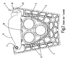
- 索形状の部材、特に風力設備におけるケーブル(5;181)又はケーブル束、を固定かつ/又は案内する装置であって、モジュール式の固定システムを形成するために支持体構造と組み合わせ可能な少なくとも1つの保持ボディ(1;101)を有し、前記保持ボディが少なくとも1つの索部材のための支承部として索収容室(9;109)を有し、前記索部材が前記索収容室内へ、その外側に設けられた開口部(29;111)を通して挿入可能であり、開口部(29;111)がカバー装置(9;117;202)によって閉鎖可能であり、前記カバー装置が押圧部分(17;129;206)を有し、前記押圧部分は、締めつけ領域の内部において索収容室(9;109)内にある索部材上へ保持力を及ぼすために、蓄勢装置(51;137;208)によって締めつけ位置へ移動可能である、索形状の部材、特に風力設備におけるケーブル(5;181)又はケーブル束、を固定かつ/又は案内する装置において、
カバー装置(9;117;202)がロック装置(69;141;200)を有し、前記ロック装置によって押圧部分(17;129;206)が蓄勢装置(51;137;208)の作用に抗して、締めつけ位置への移動に対して選択的に固定可能であり、あるいは締めつけ運動のために解放可能であることを特徴とする、索形状の部材、特に風力設備におけるケーブル(5;181)又はケーブル束、を固定かつ/又は案内する装置。 - 前記押圧部分(17;129;206)が、蓄勢装置として用いられる少なくとも1つの圧縮ばね(51;137;208)によって、メイン部分(47;127;204)に対して行われる運動のために、締めつけ位置へ付勢されており、前記圧縮ばねが保持ボディ(1;101)に取り付け可能な、カバー装置(9;117;202)のメイン部分(47;127;204)に支持される、ことを特徴とする請求項1に記載の装置。
- 前記カバー装置(9;117;202)のメイン部分(47;127;204)が、押圧部分(17;129;206)の方向へ開放したシェル部分(47;127)を有し、かつ押圧部分(17;129;206)が第2のシェル部分(49;129)の形状で形成されており、前記第2のシェル部分が第1のシェル部分(47;127)内でテレスコープ状に移動可能であり、かつ前記第2のシェル部分の底面が、索部材へ保持力を伝達する押圧器(53;131)を形成する、ことを特徴とする請求項1又は2に記載の装置。
- 前記支承部が、索部材の軸方向に離隔した2つの支承側面(19、21)を有し、前記支承側面が、それぞれ外側の開口部(29)から始まる、槽状の切り欠き(27)内で、索部材のための添接面(33、35)を形成する、ことを特徴とする請求項1〜3のいずれか1項に記載の装置。
- 前記少なくとも1つの保持ボディ(1)が、U字プロフィールの形状のフレームを有し、前記U字プロフィールにおいて2つの支承側面(19、21)が互いに対して平行に延びるプロフィール脚によって形成されており、前記プロフィール脚が、支持体構造と結合するための添接面を形成するウェブ(23)によって互いに結合されている、ことを特徴とする請求項1〜4のいずれか1項に記載の装置。
- 前記2つの支承側面(19、21)の切り欠き(27)の幅が、切り欠き(27)の底(31)における添接面(33、35)から始まって、開口部(29)の方向に段階的に拡幅されており、そのうちの下方の段部が押圧部分(49)の締めつけ運動のためのガイド面(35)を形成し、かつ開口部(29)の方向に連続する段部が、支承部に取り付けられたカバー装置(9)のための取り付け面(37)を形成している、ことを特徴とする請求項4又は5に記載の装置。
- 前記カバー装置(9)のメイン部分(47)が、押圧部分(49)の方向に開放したシェル部分を有しており、前記シェル部分が、支承部に取り付けられた位置において、索部材の軸方向に支承側面(19)から支承側面(21)へ延びており、かつそれらの間に延びる側においてガイドトラック(61)を形成し、前記ガイドトラック内で押圧部分(49)の突出部(59)が、メイン部分(47)に対して移動するために案内されている、ことを特徴とする請求項1〜6のいずれか1項に記載の装置。
- 前記押圧部分(49、206)の突出部(59;218)が、メイン部分(47;204)を越えて張り出す終端領域によって、ロック装置(59、69、71;200)の機能部材を形成する、ことを特徴とする請求項1〜7のいずれか1項に記載の装置。
- 前記ロック装置が手動で回動可能な偏心子(69)を有し、前記偏心子がメイン部分(47)の上側(63)上に支持されているので、偏心子軸線を形成する偏心子軸(71)が、回転する際にメイン部分(47)に対する往復運動を実施し、かつ、
偏心子軸(71)が押圧部分(49)の突出部(59)内の長孔(73)内へ次のように、すなわち偏心子(69)のロック位置においては押圧部分(49)が付勢するばね作用に抗してメイン部分(47)へ引きつけられており、偏心子の解放位置においては締めつけ運動のために解放されるように、嵌入する、ことを特徴とする請求項1〜8のいずれか1項に記載の装置。 - 前記2つの支承側面(19、21)が、切り欠き(27)の開口部(29)に、互いに対して張り出すフック部分(45)を有しており、前記フック部分が、支承側面(19、21)内に形成される凹部(41、43)に連続し、前記凹部はカバー装置(9)の取り付け工程において貫通可能であり、フック部分(45)がメイン部分(47)の側方に張り出すように形成されており、かつカバー装置(9)の取り付けられた位置において、保持部分(45)によって把持される、ことを特徴とする請求項4、5及び6のいずれか1項に記載の装置。
- 前記メイン部分(47)のカバープレート(65)の端部に、保持ウィング(77)が設けられており、その上にロック装置(59、69、71)の偏心子(69)が支持される、ことを特徴とする請求項7、9及び10のいずれか1項に記載の装置。
- 前記メイン部分(47)のガイドトラック(61)を有する側の、支承側面(19、21)に対応づけられた2つの端部に、撓むように張り出す係止突片(79)が設けられており、前記係止突片は、カバー装置(9)が支承部へ向けられた位置において、支承側面(19、21)の内側に係止される、ことを特徴とする請求項7、9、10及び11のいずれか1項に記載の装置。
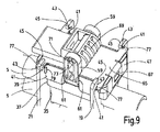
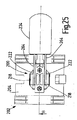
- 前記ロック装置が、手動で回動可能な偏心子(141)を有しており、前記偏心子がメイン部分(127)の上側(57)上に次のように、すなわち偏心子軸線を形成する付属のクランクピン(149)が、回動する際にメイン部分(127)に対する往復運動を実施するように、支持され、かつ、
クランクピン(149)がコネクティングロッド(151)を介して押圧部分(129)と次のように、すなわち偏心子(141)のロック位置において押圧部分(129)が付勢するばね作用に抗してメイン部分(127)に引きつけられており、偏心子(141)の解放位置においては、締めつけ運動のために解放されるように、結合されている、
ことを特徴とする請求項1〜3のいずれか1項に記載の装置。 - 前記偏心子(141)が円筒部分(145、147)を有しており、前記円筒部分がそれから張り出すハンドレバー(143)によって手動で回動可能であり、メイン部分(127)の上側(157)に支持され、かつ円筒軸線から距離を有するクランクピン(149)を有している、ことを特徴とする請求項13に記載の装置。
- 前記円筒部分が、互いに距離を有する2つの円形ディスク(145、147)によって形成されており、前記円形ディスクの間に、2つの円形ディスク(145、147)の間へ嵌入するコネクティングロッド(151)のためのクランクピン(149)が配置されている、ことを特徴とする請求項14に記載の装置。
- 前記メイン部分(127)の上側(157)に、円筒部分(145、147)の支承部としての槽(159)が形成されており、前記円筒部分が切り欠き(163)を通して前記槽内へ嵌入し、前記切り欠きが、メイン部分(127)の上側(157)に添接するカバープレート(161)内に形成されており、切り欠き(163)が互いに対向する開放端縁(165)によって画成されており、前記開放端縁が、切り欠き(163)内へ嵌入する円形ディスク(145、147)の平面に沿って延びている、ことを特徴とする請求項13〜15のいずれか1項に記載の装置。
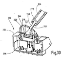
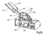
- 前記少なくとも1つの保持ボディ(101)が、互いに対向する開放端縁(113、115)を備えた挿入開口部(111)を有するU字状又はV字状の凹部(109)の形式の索収容室を有しており、前記開放端縁の1つ(115)にカバー装置(117)が次のように、すなわち開放位置と挿入開口部(111)を閉鎖する位置との間で移動可能であるように、揺動可能に取り付けられており、かつ、
カバー装置(117)にロック配置(121)が設けられており、前記ロック配置によってカバー装置が閉鎖位置において他の開放端縁(113)と取り外し可能にロック可能である、ことを特徴とする請求項13〜16のいずれか1項に記載の装置。 - 前記少なくとも1つの保持ボディ(101)が、索収容室の凹部(109)を有する、第1の平坦なプレート部分(103)と、それから屈曲されている第2のプレート部分(105)とを有する薄板曲げ部品によって形成されており、前記第2のプレート部分が、支持体構造と結合するための、挿入開口部(111)に対向する取り付け面を形成している、ことを特徴とする請求項13〜17のいずれか1項に記載の装置。
- 前記カバー装置(117)のメイン部分(127)が、第1のプレート部分(103)の挿入開口部(111)の各開放端縁(113、115)と結合するために、メイン部分(127)から逆方向に張り出すそれぞれ1対のアーム(169)を有しており、前記アームの間に、プレート部分(103)の係合を可能にする間隙が形成されている、ことを特徴とする請求項17に記載の装置。
- ロック配置(121)に対応づけられたアームペアのアーム(169)が、それぞれ長孔(173)を有しており、前記長孔内でロックボルト(171)が、開放端縁(113)に設けられたロックフックと係止されるロック位置と、引き戻されたアンロック位置との間で移動可能であって、かつ、
ロックボルト(171)をロック位置へ付勢する操作ばね(75)が設けられており、前記操作ばねは、ロック配置(121)を外すために手動で、ロックボルト(171)を引き戻す位置へ移動可能である、ことを特徴とする請求項13〜19のいずれか1項に記載の装置。
Applications Claiming Priority (3)
| Application Number | Priority Date | Filing Date | Title |
|---|---|---|---|
| DE102015013791.3A DE102015013791A1 (de) | 2015-10-22 | 2015-10-22 | Einrichtung zur Fixierung und/oder Führung von strangförmigen Elementen |
| DE102015013791.3 | 2015-10-22 | ||
| PCT/EP2016/001730 WO2017067658A1 (de) | 2015-10-22 | 2016-10-19 | Einrichtung zur fixierung und/oder führung von strangförmigen elementen |
Publications (2)
| Publication Number | Publication Date |
|---|---|
| JP2019502339A JP2019502339A (ja) | 2019-01-24 |
| JP6770065B2 true JP6770065B2 (ja) | 2020-10-14 |
Family
ID=57206197
Family Applications (1)
| Application Number | Title | Priority Date | Filing Date |
|---|---|---|---|
| JP2018515074A Active JP6770065B2 (ja) | 2015-10-22 | 2016-10-19 | 索形状の部材を固定及び/又は案内する装置 |
Country Status (8)
| Country | Link |
|---|---|
| US (1) | US10626854B2 (ja) |
| EP (1) | EP3365953B1 (ja) |
| JP (1) | JP6770065B2 (ja) |
| KR (1) | KR102221202B1 (ja) |
| CN (1) | CN108028524B (ja) |
| DE (1) | DE102015013791A1 (ja) |
| ES (1) | ES2745992T3 (ja) |
| WO (1) | WO2017067658A1 (ja) |
Families Citing this family (8)
| Publication number | Priority date | Publication date | Assignee | Title |
|---|---|---|---|---|
| DE102016015226A1 (de) * | 2016-12-21 | 2018-06-21 | Hydac Accessories Gmbh | Festlegevorrichtung |
| DE102019000055A1 (de) * | 2019-01-08 | 2020-07-09 | Senvion Gmbh | Windenergieanlage und Verfahren zurn Betreiben einer Windenergieanlage |
| CN109707603B (zh) * | 2019-03-18 | 2024-03-22 | 保定申辰泵业有限公司 | 一种开合与装卡软管的联动机构、蠕动泵泵头及蠕动泵 |
| DE102019126475B4 (de) * | 2019-10-01 | 2024-05-16 | Lisa Dräxlmaier GmbH | Kabelaufnahmevorrichtung |
| US11651869B2 (en) | 2020-06-29 | 2023-05-16 | Panduit Corp. | Thermal expansion slide with cable clamp |
| US11985793B2 (en) * | 2021-01-22 | 2024-05-14 | Dell Products L.P. | Cable sealing apparatus and methods |
| BE1029269B1 (de) * | 2021-04-01 | 2022-11-04 | Phoenix Contact Gmbh & Co | Klemmvorrichtung |
| CN117345740A (zh) * | 2022-06-27 | 2024-01-05 | 索斯科锁定技术(上海)有限公司 | 锁定装置 |
Family Cites Families (20)
| Publication number | Priority date | Publication date | Assignee | Title |
|---|---|---|---|---|
| DE821C (de) * | 1877-07-02 | F. quatram in Berlin | Expansionssteuerung für Dampfmaschinen | |
| DE695125C (de) * | 1937-07-16 | 1940-08-17 | E H Dr Phil H C Ernst Heinkel | Kabelhalter, insbesondere fuer Luftfahrzeuge |
| US2650948A (en) * | 1951-04-13 | 1953-09-01 | Boeing Co | Wire holder |
| JPH07183670A (ja) * | 1993-12-22 | 1995-07-21 | Nikko Kogyo Kk | 電線固定具 |
| US20080185183A1 (en) * | 2007-02-07 | 2008-08-07 | Chien-Chung Chen | Resonance-coordinating device for audio and video |
| US8057139B2 (en) * | 2009-01-21 | 2011-11-15 | Federal Signal Corporation | Tube restraint and methods |
| DE102010032686A1 (de) | 2010-07-29 | 2012-02-02 | Hydac Accessories Gmbh | Befestigungssystem für Leitungen, insbesondere für Kabel bei Windkraftanlagen |
| US8783629B2 (en) * | 2010-07-29 | 2014-07-22 | Hydac Accessories Gmbh | Attachment system for lines, in particular for cables for wind turbines |
| DE102010032687A1 (de) * | 2010-07-29 | 2012-02-02 | Hydac Accessories Gmbh | Befestigungssystem für Kabel, insbesondere bei Windkraftanlagen |
| DE102011012391A1 (de) * | 2011-02-25 | 2012-08-30 | Hydac Accessories Gmbh | Befestigungssystem für Kabel, insbesondere bei Windkraftanlagen |
| DE102012001407B4 (de) * | 2012-01-25 | 2015-05-28 | Hydac Accessories Gmbh | Befestigungssystem für strangförmige Funktionselemente bei Windkraftanlagen, nebst Einsatzelement |
| DE102012001408A1 (de) * | 2012-01-25 | 2013-07-25 | Hydac Accessories Gmbh | Befestigungssystem |
| DE102012001409A1 (de) * | 2012-01-25 | 2013-07-25 | Hydac Accessories Gmbh | Befestigungssystem für strangförmige Funktionselemente, insbesondere bei Windkraftanlagen |
| DE102012007416B4 (de) * | 2012-04-16 | 2016-08-18 | Hydac Accessoires GmbH | Befestigungssystem |
| DE102012013465A1 (de) * | 2012-07-09 | 2014-05-08 | Eppendorf Ag | Haltevorrichtung |
| DE102012017463A1 (de) | 2012-09-04 | 2014-03-06 | Hydac Accessories Gmbh | Befestigungssystem für Strangelemente, insbesondere bei Windkraftanlagen |
| DE102012019490A1 (de) * | 2012-10-04 | 2014-04-10 | Hydac Accessories Gmbh | System zur Führung und Lagesicherung von Strangelementen |
| DE102013010821A1 (de) * | 2013-06-28 | 2014-12-31 | Hydac Accessories Gmbh | Einrichtung zur Fixierung und/oder Führung von strangförmigen Elementen |
| DE102014004931A1 (de) * | 2014-04-05 | 2015-10-08 | Hydac Accessoires GmbH | Abstandshalteeinrichtung |
| DE102014116468B4 (de) * | 2014-11-11 | 2016-08-25 | Lisa Dräxlmaier GmbH | Befestigungselement und Kabelschacht |
-
2015
- 2015-10-22 DE DE102015013791.3A patent/DE102015013791A1/de not_active Withdrawn
-
2016
- 2016-10-19 EP EP16787326.4A patent/EP3365953B1/de active Active
- 2016-10-19 JP JP2018515074A patent/JP6770065B2/ja active Active
- 2016-10-19 CN CN201680055035.2A patent/CN108028524B/zh active Active
- 2016-10-19 ES ES16787326T patent/ES2745992T3/es active Active
- 2016-10-19 WO PCT/EP2016/001730 patent/WO2017067658A1/de active Application Filing
- 2016-10-19 US US15/759,548 patent/US10626854B2/en active Active
- 2016-10-19 KR KR1020187011099A patent/KR102221202B1/ko active IP Right Grant
Also Published As
| Publication number | Publication date |
|---|---|
| EP3365953B1 (de) | 2019-06-19 |
| US10626854B2 (en) | 2020-04-21 |
| JP2019502339A (ja) | 2019-01-24 |
| KR20180079306A (ko) | 2018-07-10 |
| DE102015013791A1 (de) | 2017-04-27 |
| EP3365953A1 (de) | 2018-08-29 |
| WO2017067658A1 (de) | 2017-04-27 |
| CN108028524B (zh) | 2020-09-25 |
| ES2745992T3 (es) | 2020-03-04 |
| KR102221202B1 (ko) | 2021-03-04 |
| US20190154008A1 (en) | 2019-05-23 |
| CN108028524A (zh) | 2018-05-11 |
Similar Documents
| Publication | Publication Date | Title |
|---|---|---|
| JP6770065B2 (ja) | 索形状の部材を固定及び/又は案内する装置 | |
| EP3245358B1 (en) | Sliding bolt latch and use thereof | |
| US10465426B2 (en) | Locking mechanism | |
| CN106122106B (zh) | 用于空气移动装置的风扇和安装支架 | |
| EP2607747B1 (en) | Cord lock | |
| US8876174B2 (en) | Motorcycle paraphernalia locking system | |
| US20080157543A1 (en) | Locking arrangement with a swivelling locking hook and a movable retaining rod for hooking into position | |
| JP5832577B2 (ja) | 電線布設用グリッパ装置 | |
| US9149117B2 (en) | Tool cabinet drawer and latching mechanism | |
| PL146832B1 (en) | Apparatus for attaching hook-up elements to sausages | |
| TR201507074A1 (tr) | Bir bağlantı elemanının bir parça üstüne veya içine tespit edilmesi için bağlantı aracı ve usul. | |
| KR101070954B1 (ko) | 창호 시스템 및 창호 시스템용 창문개폐모듈 | |
| KR102046665B1 (ko) | 가동체의 어시스트 기구 | |
| KR20140005523U (ko) | 롤 방충망의 핸들바 고정 및 해제장치 | |
| KR101832173B1 (ko) | 피봇홀더를 이용하여 도어 착탈과 도어 슬라이딩이 용이한 다중 슬라이드 도어의 연동장치 | |
| KR101738217B1 (ko) | 행거 | |
| JP6211423B2 (ja) | 打ち込み工具 | |
| KR101095903B1 (ko) | 서랍 설치구조 | |
| US8893632B1 (en) | Thread hooking device for a hemming device of a sewing machine | |
| KR101914764B1 (ko) | 도어락 세트 | |
| CN109098547A (zh) | 一种离合装置 | |
| CN2869244Y (zh) | 支撑杆 | |
| KR101129570B1 (ko) | 측부에 댐퍼가 부착된 자동폐쇄장치 | |
| KR101902476B1 (ko) | 도어용 경첩 | |
| CN109184328A (zh) | 一种锁具 |
Legal Events
| Date | Code | Title | Description |
|---|---|---|---|
| A621 | Written request for application examination |
Free format text: JAPANESE INTERMEDIATE CODE: A621 Effective date: 20190305 |
|
| A131 | Notification of reasons for refusal |
Free format text: JAPANESE INTERMEDIATE CODE: A131 Effective date: 20200512 |
|
| A521 | Request for written amendment filed |
Free format text: JAPANESE INTERMEDIATE CODE: A523 Effective date: 20200731 |
|
| TRDD | Decision of grant or rejection written | ||
| A01 | Written decision to grant a patent or to grant a registration (utility model) |
Free format text: JAPANESE INTERMEDIATE CODE: A01 Effective date: 20200825 |
|
| A61 | First payment of annual fees (during grant procedure) |
Free format text: JAPANESE INTERMEDIATE CODE: A61 Effective date: 20200924 |
|
| R150 | Certificate of patent or registration of utility model |
Ref document number: 6770065 Country of ref document: JP Free format text: JAPANESE INTERMEDIATE CODE: R150 |