EP3365953B1 - Device for fastening and/or guiding strand-shaped elements - Google Patents
Device for fastening and/or guiding strand-shaped elements Download PDFInfo
- Publication number
- EP3365953B1 EP3365953B1 EP16787326.4A EP16787326A EP3365953B1 EP 3365953 B1 EP3365953 B1 EP 3365953B1 EP 16787326 A EP16787326 A EP 16787326A EP 3365953 B1 EP3365953 B1 EP 3365953B1
- Authority
- EP
- European Patent Office
- Prior art keywords
- accordance
- main member
- cover
- strand
- pressure application
- Prior art date
- Legal status (The legal status is an assumption and is not a legal conclusion. Google has not performed a legal analysis and makes no representation as to the accuracy of the status listed.)
- Active
Links
- 238000004146 energy storage Methods 0.000 claims description 17
- 230000006835 compression Effects 0.000 claims description 12
- 238000007906 compression Methods 0.000 claims description 12
- 239000002184 metal Substances 0.000 claims description 10
- 230000004308 accommodation Effects 0.000 claims 4
- 230000036316 preload Effects 0.000 claims 1
- 238000003780 insertion Methods 0.000 description 10
- 230000037431 insertion Effects 0.000 description 10
- 238000000034 method Methods 0.000 description 5
- 230000001681 protective effect Effects 0.000 description 4
- 238000013459 approach Methods 0.000 description 2
- 239000004033 plastic Substances 0.000 description 2
- 229910000831 Steel Inorganic materials 0.000 description 1
- 230000005540 biological transmission Effects 0.000 description 1
- 230000015572 biosynthetic process Effects 0.000 description 1
- 238000004891 communication Methods 0.000 description 1
- 238000006073 displacement reaction Methods 0.000 description 1
- 230000001747 exhibiting effect Effects 0.000 description 1
- 238000001746 injection moulding Methods 0.000 description 1
- 239000002991 molded plastic Substances 0.000 description 1
- 238000012544 monitoring process Methods 0.000 description 1
- 210000001331 nose Anatomy 0.000 description 1
- 239000000243 solution Substances 0.000 description 1
- 239000010959 steel Substances 0.000 description 1
- 239000012815 thermoplastic material Substances 0.000 description 1
- 238000012546 transfer Methods 0.000 description 1
- 230000007704 transition Effects 0.000 description 1
Images


Classifications
-
- H—ELECTRICITY
- H02—GENERATION; CONVERSION OR DISTRIBUTION OF ELECTRIC POWER
- H02G—INSTALLATION OF ELECTRIC CABLES OR LINES, OR OF COMBINED OPTICAL AND ELECTRIC CABLES OR LINES
- H02G3/00—Installations of electric cables or lines or protective tubing therefor in or on buildings, equivalent structures or vehicles
- H02G3/30—Installations of cables or lines on walls, floors or ceilings
- H02G3/32—Installations of cables or lines on walls, floors or ceilings using mounting clamps
-
- F—MECHANICAL ENGINEERING; LIGHTING; HEATING; WEAPONS; BLASTING
- F03—MACHINES OR ENGINES FOR LIQUIDS; WIND, SPRING, OR WEIGHT MOTORS; PRODUCING MECHANICAL POWER OR A REACTIVE PROPULSIVE THRUST, NOT OTHERWISE PROVIDED FOR
- F03D—WIND MOTORS
- F03D80/00—Details, components or accessories not provided for in groups F03D1/00 - F03D17/00
- F03D80/80—Arrangement of components within nacelles or towers
- F03D80/82—Arrangement of components within nacelles or towers of electrical components
- F03D80/85—Cabling
-
- F—MECHANICAL ENGINEERING; LIGHTING; HEATING; WEAPONS; BLASTING
- F16—ENGINEERING ELEMENTS AND UNITS; GENERAL MEASURES FOR PRODUCING AND MAINTAINING EFFECTIVE FUNCTIONING OF MACHINES OR INSTALLATIONS; THERMAL INSULATION IN GENERAL
- F16L—PIPES; JOINTS OR FITTINGS FOR PIPES; SUPPORTS FOR PIPES, CABLES OR PROTECTIVE TUBING; MEANS FOR THERMAL INSULATION IN GENERAL
- F16L3/00—Supports for pipes, cables or protective tubing, e.g. hangers, holders, clamps, cleats, clips, brackets
- F16L3/08—Supports for pipes, cables or protective tubing, e.g. hangers, holders, clamps, cleats, clips, brackets substantially surrounding the pipe, cable or protective tubing
- F16L3/10—Supports for pipes, cables or protective tubing, e.g. hangers, holders, clamps, cleats, clips, brackets substantially surrounding the pipe, cable or protective tubing divided, i.e. with two or more members engaging the pipe, cable or protective tubing
- F16L3/1008—Supports for pipes, cables or protective tubing, e.g. hangers, holders, clamps, cleats, clips, brackets substantially surrounding the pipe, cable or protective tubing divided, i.e. with two or more members engaging the pipe, cable or protective tubing with two members engaging the pipe, cable or tubing, both being made of thin band material completely surrounding the pipe
- F16L3/1025—Supports for pipes, cables or protective tubing, e.g. hangers, holders, clamps, cleats, clips, brackets substantially surrounding the pipe, cable or protective tubing divided, i.e. with two or more members engaging the pipe, cable or protective tubing with two members engaging the pipe, cable or tubing, both being made of thin band material completely surrounding the pipe the members being joined by quick acting means
-
- F—MECHANICAL ENGINEERING; LIGHTING; HEATING; WEAPONS; BLASTING
- F16—ENGINEERING ELEMENTS AND UNITS; GENERAL MEASURES FOR PRODUCING AND MAINTAINING EFFECTIVE FUNCTIONING OF MACHINES OR INSTALLATIONS; THERMAL INSULATION IN GENERAL
- F16L—PIPES; JOINTS OR FITTINGS FOR PIPES; SUPPORTS FOR PIPES, CABLES OR PROTECTIVE TUBING; MEANS FOR THERMAL INSULATION IN GENERAL
- F16L3/00—Supports for pipes, cables or protective tubing, e.g. hangers, holders, clamps, cleats, clips, brackets
- F16L3/08—Supports for pipes, cables or protective tubing, e.g. hangers, holders, clamps, cleats, clips, brackets substantially surrounding the pipe, cable or protective tubing
- F16L3/10—Supports for pipes, cables or protective tubing, e.g. hangers, holders, clamps, cleats, clips, brackets substantially surrounding the pipe, cable or protective tubing divided, i.e. with two or more members engaging the pipe, cable or protective tubing
- F16L3/105—Supports for pipes, cables or protective tubing, e.g. hangers, holders, clamps, cleats, clips, brackets substantially surrounding the pipe, cable or protective tubing divided, i.e. with two or more members engaging the pipe, cable or protective tubing one member carrying a substantially radial tightening element
-
- F—MECHANICAL ENGINEERING; LIGHTING; HEATING; WEAPONS; BLASTING
- F16—ENGINEERING ELEMENTS AND UNITS; GENERAL MEASURES FOR PRODUCING AND MAINTAINING EFFECTIVE FUNCTIONING OF MACHINES OR INSTALLATIONS; THERMAL INSULATION IN GENERAL
- F16L—PIPES; JOINTS OR FITTINGS FOR PIPES; SUPPORTS FOR PIPES, CABLES OR PROTECTIVE TUBING; MEANS FOR THERMAL INSULATION IN GENERAL
- F16L3/00—Supports for pipes, cables or protective tubing, e.g. hangers, holders, clamps, cleats, clips, brackets
- F16L3/08—Supports for pipes, cables or protective tubing, e.g. hangers, holders, clamps, cleats, clips, brackets substantially surrounding the pipe, cable or protective tubing
- F16L3/10—Supports for pipes, cables or protective tubing, e.g. hangers, holders, clamps, cleats, clips, brackets substantially surrounding the pipe, cable or protective tubing divided, i.e. with two or more members engaging the pipe, cable or protective tubing
- F16L3/1058—Supports for pipes, cables or protective tubing, e.g. hangers, holders, clamps, cleats, clips, brackets substantially surrounding the pipe, cable or protective tubing divided, i.e. with two or more members engaging the pipe, cable or protective tubing one member being flexible or elastic
-
- F—MECHANICAL ENGINEERING; LIGHTING; HEATING; WEAPONS; BLASTING
- F16—ENGINEERING ELEMENTS AND UNITS; GENERAL MEASURES FOR PRODUCING AND MAINTAINING EFFECTIVE FUNCTIONING OF MACHINES OR INSTALLATIONS; THERMAL INSULATION IN GENERAL
- F16L—PIPES; JOINTS OR FITTINGS FOR PIPES; SUPPORTS FOR PIPES, CABLES OR PROTECTIVE TUBING; MEANS FOR THERMAL INSULATION IN GENERAL
- F16L3/00—Supports for pipes, cables or protective tubing, e.g. hangers, holders, clamps, cleats, clips, brackets
- F16L3/22—Supports for pipes, cables or protective tubing, e.g. hangers, holders, clamps, cleats, clips, brackets specially adapted for supporting a number of parallel pipes at intervals
- F16L3/223—Supports for pipes, cables or protective tubing, e.g. hangers, holders, clamps, cleats, clips, brackets specially adapted for supporting a number of parallel pipes at intervals each support having one transverse base for supporting the pipes
- F16L3/227—Supports for pipes, cables or protective tubing, e.g. hangers, holders, clamps, cleats, clips, brackets specially adapted for supporting a number of parallel pipes at intervals each support having one transverse base for supporting the pipes each pipe being supported by a separate element fastened to the base
-
- F—MECHANICAL ENGINEERING; LIGHTING; HEATING; WEAPONS; BLASTING
- F16—ENGINEERING ELEMENTS AND UNITS; GENERAL MEASURES FOR PRODUCING AND MAINTAINING EFFECTIVE FUNCTIONING OF MACHINES OR INSTALLATIONS; THERMAL INSULATION IN GENERAL
- F16L—PIPES; JOINTS OR FITTINGS FOR PIPES; SUPPORTS FOR PIPES, CABLES OR PROTECTIVE TUBING; MEANS FOR THERMAL INSULATION IN GENERAL
- F16L3/00—Supports for pipes, cables or protective tubing, e.g. hangers, holders, clamps, cleats, clips, brackets
- F16L3/22—Supports for pipes, cables or protective tubing, e.g. hangers, holders, clamps, cleats, clips, brackets specially adapted for supporting a number of parallel pipes at intervals
- F16L3/23—Supports for pipes, cables or protective tubing, e.g. hangers, holders, clamps, cleats, clips, brackets specially adapted for supporting a number of parallel pipes at intervals for a bundle of pipes or a plurality of pipes placed side by side in contact with each other
-
- H—ELECTRICITY
- H02—GENERATION; CONVERSION OR DISTRIBUTION OF ELECTRIC POWER
- H02G—INSTALLATION OF ELECTRIC CABLES OR LINES, OR OF COMBINED OPTICAL AND ELECTRIC CABLES OR LINES
- H02G3/00—Installations of electric cables or lines or protective tubing therefor in or on buildings, equivalent structures or vehicles
- H02G3/02—Details
- H02G3/04—Protective tubing or conduits, e.g. cable ladders or cable troughs
- H02G3/0456—Ladders or other supports
-
- Y—GENERAL TAGGING OF NEW TECHNOLOGICAL DEVELOPMENTS; GENERAL TAGGING OF CROSS-SECTIONAL TECHNOLOGIES SPANNING OVER SEVERAL SECTIONS OF THE IPC; TECHNICAL SUBJECTS COVERED BY FORMER USPC CROSS-REFERENCE ART COLLECTIONS [XRACs] AND DIGESTS
- Y02—TECHNOLOGIES OR APPLICATIONS FOR MITIGATION OR ADAPTATION AGAINST CLIMATE CHANGE
- Y02E—REDUCTION OF GREENHOUSE GAS [GHG] EMISSIONS, RELATED TO ENERGY GENERATION, TRANSMISSION OR DISTRIBUTION
- Y02E10/00—Energy generation through renewable energy sources
- Y02E10/70—Wind energy
- Y02E10/72—Wind turbines with rotation axis in wind direction
Definitions
- the invention relates to a device for fixing and / or guiding strand-like elements, in particular of cables or cable bundles in wind turbines, with at least one to form a modular fastening system with a support structure combinable holding body having a strand receiving space as storage for at least one strand element, the in this can be inserted through an opening located on the outside thereof, wherein the opening can be closed by a covering device, which has a pressing part, which is movable by means of an energy storage in a clamping position to exert a holding force on stranded in the strand receiving space within a clamping range.
- string elements such as power transmission cables, hoses, pipes and / or conduits for control or communication purposes leading from the nacelle into the tower are attached corresponding support structures, especially on the tower segments, reliably set.
- the holding body can be arranged in a straight line next to each other, as in the case of DE 10 2010 032 686 A1 known solution is the case, or may be arranged in succession along a partial arc or a circular arc, wherein the openings of the storage for strand elements forming holding body are located radially outward.
- the pressing part of the closure means provided for closing the opening of the holding body is loaded by means of a spring assembly in order to exert a holding force on strands located in the storage.
- holding forces of about 200 N to 400 N are required for use in wind power plants, where high cable weights must be manageable. In the process of closing the openings of the holding body therefore correspondingly high closing forces are overcome, so that the operation of the known facilities for the operator relatively cumbersome and time-consuming designed accordingly.
- the invention has the object to provide a device of the type mentioned is available, which is particularly easy and convenient to operate.
- this object is achieved in a device of the type mentioned in that the cover has a locking device by means of which the pressing against the action of the energy storage against movement in the clamping position selectively securable or releasable for a clamping movement is.
- the pressing member is biased by at least one serving as an energy storage compression spring, which is supported on the attachable to the holding body main part of the cover, for the movement relative to the main part movement in the clamping position.
- a spring assembly may be provided from a plurality of compression springs, wherein in a rectangular main body preferably one each supported on the four corner regions.
- the bearing has two bearing cheeks spaced apart in the axial direction of the clamping elements, which in each case form the contact surfaces for strand elements in a trough-like recess which extends from the opening on the outside.
- the contact surfaces formed in the trough-like recesses may be adapted in shape to the relevant different types, shapes and sizes of strand elements or bundles.
- the holding body has a frame in the form of a U-profile, wherein the bearing cheeks are formed by mutually parallel profile legs, which are interconnected by a an attachment surface for the connection to the support structure forming web.
- the U-profile may be a bent part made of sheet metal, wherein the profile legs forming the bearing cheeks may be extended to form a profile strip, which forms a corresponding number of holding bodies in succession.
- the arrangement can be made so that the width of the recesses of the bearing cheeks, starting from the contact surfaces at the bottom of the recesses in the direction of the opening, is extended in stages, of which lower stages guide surfaces for the clamping movement of the Andrückteils and subsequent to the opening stages forming seating surfaces for the mounted on the storage cover.
- the recesses of the bearing cheeks thereby form both a seat for the cover closing the opening and the guide for the movable pressing member.
- the main part of the cover has an open towards the pressing member shell part, which extends at bearing mounted position in the axial direction of the strand elements from bearing cheek to bearing cheek and forms at the extending therefrom sides guideways in which approaches the Andrückteils are guided for its relative to the main body movements.
- the compression springs can be arranged.
- the locking device may particularly advantageously have a manually rotatable eccentric, which is supported on the upper side of the main part, so that the eccentric shaft forming the eccentric shaft performs a lifting movement relative to the main body during rotation, wherein the eccentric shaft engages in a slot in the lugs of the pressing member such in that, in the locking position of the eccentric, the pressing part is pulled against the biasing spring action on the main part and released in the release position of the eccentric for the clamping movement.
- the arrangement can be made so that the bearing cheeks have at the opening of the recesses against each other projecting hook parts which adjoin depressions in the bearing cheeks, which areteurgreifbar in the process of attaching the cover of retaining wings, which laterally projecting on the main body and are overlapped by the hook parts in the attached position.
- the cover can be safely determined by the positive engagement over the hook parts on the respective holding body.
- the retaining wings may be provided at the ends of a cover plate of the main part, on which the eccentric of the locking device is supported.
- a cover plate may be formed, for example, as a sheet metal part, which may be clipped to the existing example of plastic, shell-like body and contribute to the structural strength of the entire body, with the metallic retaining wings secure fixing of the covering is guaranteed at the opening of storage.
- the arrangement can also be made with advantage so that on both sides of the bearing cheeks associated ends of the guideways having sides of the main part resiliently projecting locking lugs are provided which engage in aligned with the storage position of the cover on the inner sides of the bearing cheeks.
- the attachment of the cover at the opening of the respective holding body is characterized particularly simple and convenient, because the lateral insertion of the retaining wings in the recesses under the hook parts of the bearing cheeks by the engagement of the locking lugs, the reaching of the alignment position of the cover is signaled.
- the locking device may particularly advantageously have a manually rotatable eccentric located on top of the main part supported such that an associated, the eccentric axis forming crank pin performs a lifting movement relative to the main body, wherein the crank pin is coupled to the pressing member via a connecting rod such that in the locking position of the eccentric, the pressing member is pulled against the biasing spring action on the main body and is released at the release position of the eccentric for the tensioning movement.
- the eccentric on a cylinder part which is manually rotatable by means of a cantilevered by him hand lever, is supported on the upper side of the main part and having the located at a distance from the cylinder axis crank pin.
- the arrangement can be made with particular advantage so that the cylinder part is formed by two spaced-apart circular disks, between which the crank pin is arranged for engaging between the circular disks connecting rod.
- a recess may be formed as a bearing of the cylinder part at the top of the main part, in which the cylinder part engages through a recess which is recessed in a cover plate, which rests against the top of the main part, wherein the recess by opposing one another Opening edges is limited, which extend along the planes of the engaging in the recess circular discs.
- the holding body has a strand receiving space in the form of a U- or V-shaped recess with an insertion opening with opposite opening edges, at one of which the cover is pivotally mounted such that it can be moved between an open position and a closing position of the insertion is, wherein on the cover means a latch assembly is provided by means of which it is releasably lockable in the closing position with the other opening edge of the insertion opening.
- the holding body is formed by a bent sheet metal part having a first flat plate part, which has the recess of the strand receiving space, and a second plate part angled therefrom, which forms a mounting surface opposite the insertion opening for connection to a respective support structure.
- the bent sheet metal part can be extended to an angle rail, wherein in the first plate member forming profile legs adjacent the recesses forming the strand receiving spaces are recessed side by side.
- the arrangement may be such that the main part of the cover means for connection with each opening edge of the respective insertion opening of the first plate member each having a pair of main body in the opposite direction cantilevered arms, between which formed an engagement of the plate member enabling space is.
- the arms of the arm assembly associated arm pair may each have a slot in which a locking bolt between a latch position in which it is latched with a latch hook at the respective opening edge, and a retracted Entriegel ein is movable, wherein the latch bolt biasing the latch position actuating spring is present, which is manually movable to release the latch assembly in a locking bolt retracting position.
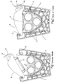
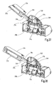
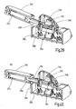
- the Fig. 1 and 2 show a corresponding prior art device for fixing and / or guiding cables or cable bundles a holding body 1 in a single representation without associated support structure.
- the holding body 1 has a trough-like recess 3 as a storage and implementation for strand elements, which tapers like a V-shape at the bottom, wherein in the recess 3, a bundle of three cables 5 is inserted from an upper opening 7 ago ,
- the Fig. 1 shows the opened state of the holding body 1, wherein a cover 9 is pivoted into a position releasing the opening 7.
- the Fig. 1 shows the opened state of the holding body 1, wherein a cover 9 is pivoted into a position releasing the opening 7.
- the cover 9 for applying a holding force on inserted cable 5 a pressing member 17, which is for a clamping movement relative to the main part of the cover 9 according to the prior art by a befindliches inside the cover 9, in Fig. 1 and 2 invisible spring package is biased. It shows Fig. 1 the over the available clamping range fully extended position of the pressing member 7, while Fig. 2 the holding force transmitting tensioned position of the pressing member 17 shows.
- the respective holding body 1 are formed by a frame which has a bent part made of sheet metal in the form of a U-profile body.
- This has as storage for strand elements bearing cheeks 19 and 21, which are formed by mutually parallel, planar profile legs of the U-profile, which are connected by a likewise planar, to the bearing cheeks 19, 21 perpendicular profile web 23 together.
- This serves as a mounting surface for the connection of the respective holding body 1 with the (not shown) support structure, for example by means of mounting holes 25 in the web 23.
- the storage in the bearing cheeks 19, 21 each have a recess 27th on, starting from a located at the free end of the bearing cheeks 19, 21 opening 29 starting the shape of a trough, whose width tapers towards the trough bottom 31 in the manner of a V-shape.
- the trough bottom 31 region of the edge of the recesses 27 contact surfaces 33 and 35 for inserted strand elements, of which in the Fig. 7 to 9 two cables 5 are visible.
- the recesses 27 extended in stages, with mutually parallel and vertically extending in the direction of the profile web 23 step surfaces 37 and 39 are formed.
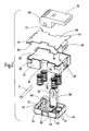
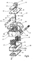
- the cover 9 whose items in Fig. 4 are shown in exploded exploded view, a main part 47 and a pressing member 49 which is movable relative to the main part 47 for a lifting movement over a clamping range.
- the pressing member 49 is biased in the manner mentioned in the relevant prior art by means of a package of four compression springs 51.
- the Fig. 5 shows the pressing member 49 in the fully extended clamping position, while in Fig. 6 the pressing member 49 is retracted against the action of the compression springs 51 and locked in this position.
- the main part 47 has the shape of a generally rectangular shell part, which is open in the direction of the pressing member 49.
- the pressing member 49 also has a main portion 47 adapted shell shape, wherein the shell bottom outside the pusher 53 forms, which exerts the retaining force on strand elements with projecting ribs 55.
- the shell of the pressing member 49 is guided on the inner shell walls of the main part 47 for lifting or clamping movements and forms together with the shell of the main part 47, the spring housing for sitting in the four corner areas on pin 57 compression springs 51.
- Main part 47 and pressing member 49 are respectively formed integrally, for example by injection molding preferably made of a thermoplastic material.
- the pressing member 49 has on its long sides on opposite projections 59, which extend perpendicularly from the bottom 53 forming the pusher surface.
- the lugs 59 form a guide body for the lifting and clamping movements of the pressing member 49 as well as part of the locking device.
- the lugs 59 are guided in guide tracks 61, which are formed on the long sides of the main part 47, which extends in mounted on the storage of the holding body 1 position in the axial direction of the strand elements from bearing cheek 19 to bearing che 21.
- the projections 59 extend beyond the upper side 63 of the main part 47, on which a flat cover plate 65 is made of sheet metal, which is clipped by means of bent tabs 67 located on the front sides of the main part 47 noses 68.
- Main parts of the locking device are in addition to the lugs 59 an eccentric 69 with an eccentric shaft 71.
- the eccentric shaft 71 of the eccentric 69 which is movable between the lugs 59, in the lugs 59 each have a slot 73 is formed. This runs in the direction of the lifting movement of the pressing member 49 over a distance corresponding to the full stroke length or the clamping range of the pressing member 49.
- the eccentric shaft 71 Under the action of the spring bias is the eccentric shaft 71, which engages with their ends in the slots 73, at the upper end of the slots 73 at. If the means of an integrally formed hand lever 75 rotatable, on the cover plate 65 supporting eccentric 69 in the in Fig. 3 .
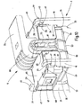
- Fig. 7 to 10 illustrate the operation of the device according to the invention, wherein Fig. 7 shows the beginning of a mounting operation of the cover 9 for closing the opening 29 of the holding body 1, in which two strand elements in the form of cables 5 are inserted.
- the cover plate 65 of the cover 9 in the corner regions laterally projecting retaining wings 77 on.
- this is, starting from the in Fig. 7 shown position, offset in the axial direction of the cable 5, to the bearing cheeks 19, 21, inserted through the opening 29 between the bearing cheeks 19, 21 until the wings 77 are aligned with the recesses 41 of the bearing cheeks 19, 21.
- the wings 77 are, as most clearly from the Fig. 4 . 7 and 8th is to be seen, stepped and dimensioned in their length so that the outer step can pass through the lower recess 41 of the bearing cheeks 19, 21, but not through the upper recess 43. In with inserted strand elements supported Andrückteil 49 and thereby raised by the spring force main body 47 is therefore the most projecting step of the wings 77, above the bottom of the recesses 43 above, on the outer sides of the bearing cheeks 19, 21 to axially secure the cover 9.
- the procedure is such that the pressing member 49 is locked, so that the cover 9 is moved downward without any effort to align the wings 77 on the recesses 41.
- the axial displacement can take place until, after the passage of the wings 77 through the recesses 41, the covering device 9 is free for removal.
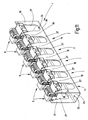
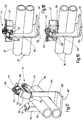
- the Fig. 11 shows an embodiment of the device according to the invention, in which the frame formed by a U-profile for several interconnected holding body, in the example shown for six holding body 1, is extended to a profile strip 81.
- the profile legs connected by the profile web 23 form the bearing-forming recesses 27, which are similarly shaped, as described above.
- a holding body 101 shown by a further embodiment.
- a corresponding number of holding bodies 101 may be provided and attached to the relevant support structure, such as a tower segment.
- the holding bodies 101 may be arranged next to each other in a straight sequence according to the type and shape of the attachment region on the support structure or in an arcuate course.
- the holding bodies 101 are formed by a bent part, which is bent from a rectangular sheet steel plate such that a first plate part 103 is formed, from which a shorter, second plate part 105 is bent at right angles.
- the second plate member 105 forms a flat mounting surface 107 for connection to the respective support structure, for example by screwing means not shown screw holes in the second plate member 105.
- the first plate member 103 forms a strand receiving space in the form of a U-shaped recess 109 for einer strand elements on the the second plate portion 105 opposite upper end has an insertion opening 111 which is bounded by opening edges 113 and 115.
- the bent sheet metal part can be extended to a number of holding body forming angle rail, in which the recesses 109 are formed in the first plate member 103 forming profile leg successively.
- the covering device 117 is in a position closing the opening 111 of the depression 109 (FIG. Fig. 12 ) or in an opening 111 releasing the open position ( Fig. 13 ).
- one of the covering device 117 associated locking device is in each case in its locking position.
- the details of the cover 117 and its locking device are in the Fig. 14 to 16 shown in more detail.
- the cover device is articulated for a pivoting movement by means of a pivot bearing 119 on the opening edge 115 of the plate part 103 of the holding body 101.
- a releasable latch assembly 121 which has a locking bolt 123, which is suitable for movement between a latch position, in the he with a latch hook 125 at the opening edge 113 is in positive engagement, and one of them withdrawn unlocking position is adjustable in position.
- Fig. 14 to 16 show, the cover 117 as a main part of a shell member 127 which is rectangular and open in the direction of a pressing member which transmits the holding force to be fixed to strand elements.
- This pressing member is formed by a second shell portion 129 which is adapted in shape to the first shell portion 127 and is telescopically movable in this, so that it, as the comparison of FIGS. 15 and 16 shows, a lifting movement between ejected clamping positions or a retracted position can perform in Fig. 15 is shown and in which the pressing part forming the second shell part 129 is securable by means of a locking device.
- the bottom 131 of the second shell part 129 forms the pusher, which cooperates via a voltage applied to the outside of the bottom 131, plate-shaped protective backing 133 with the strand elements to be fixed.
- the protective backing 133 has an outer contouring with projecting nubs 135.
- First shell part 127, second shell part 129 and protective backing 133 are injection-molded plastic parts.
- a spring assembly of six helical compression springs 137 one of which is arranged in each corner of the rectangular shape and one on the longitudinal center line of the rectangular shape, wherein the compression springs 137 are positioned on pins 139 projecting from the protective base 133 and from the inside of the first shell part 127.
- the locking device by means of which the pressing part forming the second shell part 129 against the action of the spring assembly in the inter alia in Fig. 15 shown, retracted position is securable, has an eccentric 141 which is manually rotatable by means of a hand lever 431.
- the eccentric 141 is formed together with the hand lever 143 by a one-piece plastic part, which consists of two circular discs 145 and 147th formed cylinder part, from which the hand lever 143 protruding extends.
- the circular disks 145, 147 are arranged at a distance from each other.
- a crank pin 149 extends, which is positioned at a location radially offset to the cylinder axis and thereby performs a stroke movement upon rotation of the circular disks 145, 147.
- a connecting rod 151 is provided which engages in the intermediate space between the circular discs 145, 147 and a slot 153, in which the crank pin 149 engages.
- the second shell part 129 facing the end of the connecting rod 151 is hinged to a hinge pin 150 on a bearing block 155 which is integrally formed on the bottom part 131 of the second shell part 129.
- the Fig. 16 shows the eccentric 141 in a release position of the pressing member corresponding rotational position in which the crank pin 149 is below the top 157 of the formed by the first shell portion 127 and the pressure lever 143 on the in Fig. 16 Left side located part of the top 157 rests.
- the pressing member forming the second shell part 129 is locked in the retracted position against the spring force by the compression springs 137.
- FIGS. 15 and 16 is at the top 157 of the main part forming the first shell portion 127 .
- a circular arc arched trough 159 is formed, which forms a kind of bearing seat during the rotation of the circular disks 145, 147.
- a cover plate 161 made of sheet metal, in the central region, as shown Fig. 14 can be seen, a rectangular recess 163 is recessed, which surrounds the trough 159.
- the longitudinal side edges 165 and 167 of the recess 163 form a lateral guide for the circular disks 145, 147 engaging in the recess 159, so that the eccentric 141 is secured in a defined position on the upper side 157 in conjunction with the pivot bearing formed by the recess 159.
- arms 169 are integrally formed on two opposite sides of the first shell portion 127, between which a engagement of the end portion of the first plate portion 103 of the holding body 101 enabling space is. This in FIGS. 12 and 13 on the right-most pair of arms 169 is by means of a pivot bearing 119 forming the pivot pin 171 ( Fig. 14 ) is hinged next to the opening edge 115 on the first plate part 103.
- the latch assembly 121 associated pair of arms 169 has a slot 173 in which a latch bolt 173 of the latch assembly 121 between a latch position in which it is latched to the latch hook 125 at the opening edge 113, and a retracted latch position is movable a locking spring biasing the locking bolt 123 into the locking position 175 is provided.
- Fig. 14 shows a fixing part 177, which is fixed to the first shell portion 127 below the cover plate 161, and at the other end a tab 179, which includes the central region of the locking bolt 123.
- the spring 175 forms an actuating device, which on the one hand generates the bias of the locking bolt 123, but on the other hand is accessible between the arms 169 for manual operation, such as Fig. 12 shows, and thereby the retraction of the locking bolt 123 allows in the unlocked position.
- the Fig. 14 shows that the arms 169 are laterally edged and reinforced by sheet metal parts 185, which are connected to each other via webs 187 extending in grooves 189 in the top 157 of the first shell part 127.
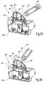
- the 17 to 19 illustrate the sequence of the fixing process for two cables 181.
- the Fig. 17 shows the cover 117 in the pivoted in the open position position, wherein the pressing member is locked in the retracted position.
- the cover 119 is already in the insertion opening 111 occluding position, wherein the pressing member is still locked, so that, since no spring force on the pressing member is effective, the pivoting is done in the closed position without effort.
- the Fig. 19 Finally, shows the final state in which the pressing member is released after unlocking the locking device for the clamping movement and exerts the holding force on the inserted cable 181.
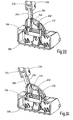
- FIGS. 20 to 40 Another alternative of the locking device 200 of a cover device 202 according to the invention is in the FIGS. 20 to 40 shown.
- a cup-shaped main part 204 is provided, in which a likewise cup-shaped pressing member 206 is arranged to be telescopically displaceable.
- the main part 204 and the pressing part 206 are rectangular and four energy storage 208 are provided, which space the parts 204, 206 from each other.
- a bottom plate 210 is inserted, which has recesses for the energy storage 208 positioning pin 214. Furthermore protrude in the interior 216 of the pressing member 206 two parallel projections 218 with slots 220 in the direction of the main part 204 up and pass through the opening slots 222 of the main body 204th
- a recess 224 is provided on the upper side 226 of the main part 204.
- a strip-shaped bearing plate 228 is arranged in this recess 224.
- the main part 204 between the slots 222 has a thickened center part 230.
- a guide part 232 for an actuating lever 234 is provided on the upper side 226 of the main part 204.
- the guide member 232 is attached via two parallel bolts 236 on the central part 230 of the main part 204, wherein the bolts 236 pass through openings 238 in the bearing plate 228.
- the guide member 232 On its underside 240, the guide member 232 has laterally two recessed recesses 242 for bearing pin 244 described below.
- the guide part 232 On its upper side 246, the guide part 232 is provided with an asymmetrically shaped, rounded guide surface 248 for a latch part 250.
- the guide surface 248 runs along a left side surface 252 in the image plane and merges via a rounding 254 into a curved surface section 256 on the upper side 246 of the guide part 232 and then via a further rounding 258 into a right side surface 260 of the guide part 232.
- the curved central surface portion 256 has a maximum height H232 in the vicinity of the left side surface 252 and then extends with a cross-sectionally approximately circular portion-shaped curve 262 to the right side surface 260th
- the operating lever 234 is provided.
- the actuating lever 234 has two cheek parts 264 which, arranged in parallel, extend laterally of the guide part 232 and are pivotally attached there.
- the cheek parts 264 each have a thickened end portion 266 and provided in the longitudinal axis of the cheek portion 264 bore 268, in which the bearing pin 244 is fixed, which is supported on the bearing plate 228 and can slide on this and in the recess 242 of Guide member 232 is movable.
- Eccentric to the bore 268 for the bearing journal 244 of the respective cheek part 264 is in the end part 266 another Bore 270 is provided, which is located in the axial direction of the cheek part 264 between the bore 268 for the bearing pin 244 and an actuating part 272.
- a lifting pin 274 is fixed, which engages in the slot 220 of the adjacent projection 218 of the pressing member 206 to lift the pressing member 206 against the action of the energy storage 208 and to lock in the raised position AS.
- the actuating part 272 of the actuating lever 234 has two shell parts 276, 278, which are screwed together by bolts 280. Between the shell parts 276, 278 and the cheek parts 264, the latch part 250 is provided in the center of the operating lever 234.
- the latch member 250 is slidably disposed in the longitudinal direction LR of the actuating lever 234 and is acted upon by a further energy storage 282, in particular a gas spring or a helical compression spring which is arranged in the actuating part 272 in the direction of the guide surface 248 of the guide member 232.
- the latch member 252 is piston-shaped and preferably provided with a blind hole 284 for receiving and guiding the further energy storage 282.
- the latch member 250 is guided along the guide surface 248 of the guide member 232. In this case, it is displaced by the guide surface 248 in the operating part 272 against the action of the further energy storage 282. In this case, an additional force must be expended by an operator during pivoting of the actuating lever 234 for a slide-in movement.
- the latch member 250 When the operating lever 234 is pivoted from the unlocked position ES to the locking position VS, the latch member 250 is first displaced along the right side surface 260 of the guide member 232, the latch member 250 being slightly slid into the operating member 272. In this way, a resistance must be overcome to move the operating lever 234 from the unlocked position ES. If this resistance is overcome, the latch member 250 is displaced along the arcuate guide surface 248 of the guide member 232. In this pivoting region, the latch member 250 is held in position relative to the actuating member 272 or slightly shifted with increasing pivot angle in the operating part 272, so that in this pivoting range of the pivoting movement of the actuating lever 234 either no force or only a very small increasing force by the latch member 250th is opposed.
- the cover 202 also in this embodiment, a locking device 200, by means of which the pressing member 206 against the action of an energy storage 208 against movement into the clamping position selectively securable (locking position VS) or for a clamping movement (in the unlocked position ES) is releasable.
Description
Die Erfindung betrifft eine Einrichtung zur Fixierung und/oder Führung von strangförmigen Elementen, insbesondere von Kabeln oder Kabelbündeln bei Windkraftanlagen, mit mindestens einem zur Bildung eines modularen Befestigungssystems mit einer Trägerstruktur kombinierbaren Haltekörper, der einen Strangaufnahmeraum als Lagerung für zumindest ein Strangelement aufweist, das in diesen durch eine an dessen Außenseite befindliche Öffnung einlegbar ist, wobei die Öffnung durch eine Abdeckeinrichtung verschließbar ist, die ein Andrückteil aufweist, das mittels eines Energiespeichers in eine Spannposition bewegbar ist, um innerhalb eines Spannbereichs eine Haltekraft auf im Strangaufnahmeraum befindliche Strangelemente auszuüben.The invention relates to a device for fixing and / or guiding strand-like elements, in particular of cables or cable bundles in wind turbines, with at least one to form a modular fastening system with a support structure combinable holding body having a strand receiving space as storage for at least one strand element, the in this can be inserted through an opening located on the outside thereof, wherein the opening can be closed by a covering device, which has a pressing part, which is movable by means of an energy storage in a clamping position to exert a holding force on stranded in the strand receiving space within a clamping range.
Um die in Windkraftanlagen erzeugten Energien abzuführen sowie für andere betriebliche Zwecke, wie Steuerung, Überwachung und dergleichen, sind Strangelemente, wie Kabel zur Leistungsübertragung, Schläuche, Rohre und/oder Leitungen für Steuerungs- oder Kommunikationszwecke, die vom Maschinenhaus in den Turm führen, an entsprechenden Trägerstrukturen, insbesondere an den Turmsegmenten, zuverlässig festzulegen. Als Beispiele für den diesbezüglichen Stand der Technik sind Einrichtungen der eingangs genannten Gattung in den Dokumenten
Weitere Einrichtungen zur Fixierung und/oder Führung von strangförmigen Elementen gehen aus der
Ausgehend von diesem Stand der Technik stellt sich die Erfindung die Aufgabe, eine Einrichtung der eingangs genannten Gattung zur Verfügung zu stellen, die besonders einfach und bequem betätigbar ist.Based on this prior art, the invention has the object to provide a device of the type mentioned is available, which is particularly easy and convenient to operate.
Entsprechend dem kennzeichnenden Teil des Anspruchs 1 ist diese Aufgabe erfindungsgemäß bei einer Einrichtung der eingangs genannten Gattung dadurch gelöst, dass die Abdeckeinrichtung eine Verriegelungseinrichtung aufweist, mittels der das Andrückteil gegen die Wirkung des Energiespeichers gegen eine Bewegung in die Spannposition wahlweise sicherbar oder für eine Spannbewegung freigebbar ist. Bei verriegeltem Andrückteil und dadurch unwirksam gemachtem Energiespeicher lässt sich die Öffnung der jeweiligen Lagerung der Haltekörper ohne großen Kraftaufwand durch die Abdeckeinrichtung verschließen, so dass die erfindungsgemäße Einrichtung einfach und bequem und dadurch mit geringem Zeitaufwand betätigbar ist. Vorteilhafterweise ist das Andrückteil durch mindestens eine als Energiespeicher dienende Druckfeder, die sich an dem am Haltekörper anbringbaren Hauptteil der Abdeckeinrichtung abstützt, für die relativ zum Hauptteil erfolgende Bewegung in die Spannposition vorgespannt. Dabei kann ein Federpaket aus mehreren Druckfedern vorgesehen sein, wobei sich bei einem rechteckförmigen Hauptteil vorzugsweise je eine an dessen vier Eckbereichen abstützt.According to the characterizing part of
Bei besonders vorteilhaften Ausführungsbeispielen weist die Lagerung zwei in Axialrichtung der Spannelemente beabstandete Lagerwangen auf, die in jeweils einer von der Öffnung an der Außenseite ausgehenden, muldenartigen Ausnehmung die Anlageflächen für Strangelemente bilden. Die in den muldenartigen Ausnehmungen gebildeten Anlageflächen können in ihrer Formgebung an die in Frage kommenden unterschiedlichen Arten, Formen und Größen von Strangelementen oder -bündeln angepasst sein.In particularly advantageous embodiments, the bearing has two bearing cheeks spaced apart in the axial direction of the clamping elements, which in each case form the contact surfaces for strand elements in a trough-like recess which extends from the opening on the outside. The contact surfaces formed in the trough-like recesses may be adapted in shape to the relevant different types, shapes and sizes of strand elements or bundles.
Bei besonders vorteilhaften Ausführungsbeispielen weist der Haltekörper ein Gestell in Form eines U-Profils auf, bei dem die Lagerwangen durch parallel zueinander verlaufende Profilschenkel gebildet sind, die durch einen eine Anbringfläche für die Verbindung mit der Trägerstruktur bildenden Steg miteinander verbunden sind. Dabei kann das U-Profil ein Biegeteil aus Metallblech sein, wobei die die Lagerwangen bildenden Profilschenkel zur Bildung einer Profilleiste verlängert sein können, die eine entsprechende Anzahl von Haltekörpern in Aufeinanderfolge bildet.In particularly advantageous embodiments, the holding body has a frame in the form of a U-profile, wherein the bearing cheeks are formed by mutually parallel profile legs, which are interconnected by a an attachment surface for the connection to the support structure forming web. The U-profile may be a bent part made of sheet metal, wherein the profile legs forming the bearing cheeks may be extended to form a profile strip, which forms a corresponding number of holding bodies in succession.
Mit besonderem Vorteil kann die Anordnung so getroffen sein, dass die Weite der Ausnehmungen der Lagerwangen, ausgehend von den Anlageflächen am Grund der Ausnehmungen in Richtung auf die Öffnung hin, in Stufen erweitert ist, von denen untere Stufen Führungsflächen für die Spannbewegung des Andrückteils und sich in Richtung der Öffnung anschließende Stufen Sitzflächen für die an der Lagerung angebrachte Abdeckeinrichtung bilden. Die Ausnehmungen der Lagerwangen bilden dadurch sowohl einen Sitz für die die Öffnung verschließende Abdeckeinrichtung als auch die Führung für das bewegbare Andrückteil.With particular advantage, the arrangement can be made so that the width of the recesses of the bearing cheeks, starting from the contact surfaces at the bottom of the recesses in the direction of the opening, is extended in stages, of which lower stages guide surfaces for the clamping movement of the Andrückteils and subsequent to the opening stages forming seating surfaces for the mounted on the storage cover. The recesses of the bearing cheeks thereby form both a seat for the cover closing the opening and the guide for the movable pressing member.
Bei vorteilhaften Ausführungsbeispielen weist das Hauptteil der Abdeckeinrichtung ein in Richtung auf das Andrückteil offenes Schalenteil auf, das sich bei an der Lagerung angebrachter Position in Axialrichtung der Strangelemente von Lagerwange zu Lagerwange erstreckt und an den zwischen diesen verlaufenden Seiten Führungsbahnen bildet, in denen Ansätze des Andrückteils für dessen relativ zum Hauptteil erfolgende Bewegungen geführt sind. Mit Vorteil können dabei die Ansätze mit einem über das Hauptteil überstehenden Endbereich Funktionselemente der Verriegelungseinrichtung, also die Wirkverbindung zwischen Andrückteil und Verriegelungseinrichtung, bilden. Im Innenraum des Schalenteiles können die Druckfedern angeordnet sein.In advantageous embodiments, the main part of the cover has an open towards the pressing member shell part, which extends at bearing mounted position in the axial direction of the strand elements from bearing cheek to bearing cheek and forms at the extending therefrom sides guideways in which approaches the Andrückteils are guided for its relative to the main body movements. Advantageously, the approaches with a projecting over the main part end portion functional elements of the locking device, so the operative connection between the pressing and locking device, form. In the interior of the shell part, the compression springs can be arranged.
Die Verriegelungseinrichtung kann mit besonderem Vorteil einen manuell drehbaren Exzenter aufweisen, der sich auf der Oberseite des Hauptteils abstützt, so dass die die Exzenterachse bildende Exzenterwelle bei Drehung eine Hubbewegung relativ zum Hauptteil ausführt, wobei die Exzenterwelle in ein Langloch in den Ansätzen des Andrückteils derart eingreift, dass bei der Verriegelungsstellung des Exzenters das Andrückteil gegen die vorspannende Federwirkung an das Hauptteil gezogen ist und bei der Freigabestellung des Exzenters für die Spannbewegung freigegeben ist. Dadurch, dass dergestalt das den Energiespeicher bildende Federpaket mittels eines Exzenters spannbar ist, lässt sich die Verriegelungseinrichtung mit geringem, für das Drehen des Exzenters erforderlichem Kraftaufwand betätigen.The locking device may particularly advantageously have a manually rotatable eccentric, which is supported on the upper side of the main part, so that the eccentric shaft forming the eccentric shaft performs a lifting movement relative to the main body during rotation, wherein the eccentric shaft engages in a slot in the lugs of the pressing member such in that, in the locking position of the eccentric, the pressing part is pulled against the biasing spring action on the main part and released in the release position of the eccentric for the clamping movement. The fact that in such a way that the energy storage forming spring assembly can be tensioned by means of an eccentric, the locking device can be operated with a small, required for the rotation of the eccentric force.
Mit Vorteil kann die Anordnung so getroffen sein, dass die Lagerwangen an der Öffnung der Ausnehmungen gegeneinander vorspringende Hakenteile aufweisen, die sich an Vertiefungen in den Lagerwangen anschließen, die beim Vorgang des Anbringens der Abdeckeinrichtung von Halteflügeln durchgreifbar sind, die am Hauptteil seitlich auskragend angeordnet und bei der angebrachten Position von den Hakenteilen übergriffen sind. Die Abdeckeinrichtung lässt sich durch das formschlüssige Übergreifen der Hakenteile sicher am betreffenden Haltekörper festlegen.Advantageously, the arrangement can be made so that the bearing cheeks have at the opening of the recesses against each other projecting hook parts which adjoin depressions in the bearing cheeks, which are durchgreifbar in the process of attaching the cover of retaining wings, which laterally projecting on the main body and are overlapped by the hook parts in the attached position. The cover can be safely determined by the positive engagement over the hook parts on the respective holding body.
Die Halteflügel können an den Enden einer Deckplatte des Hauptteils vorgesehen sein, auf der sich der Exzenter der Verriegelungseinrichtung abstützt. Eine derartige Deckplatte kann beispielsweise als Blechteil ausgebildet sein, das mit dem beispielsweise aus Kunststoff bestehenden, schalenartigen Hauptteil verclipst sein und zur Strukturfestigkeit des gesamten Hauptteils beitragen kann, wobei durch die metallischen Halteflügel eine sichere Festlegung der Abdeckeinrichtung an der Öffnung der Lagerung gewährleistet ist.The retaining wings may be provided at the ends of a cover plate of the main part, on which the eccentric of the locking device is supported. Such a cover plate may be formed, for example, as a sheet metal part, which may be clipped to the existing example of plastic, shell-like body and contribute to the structural strength of the entire body, with the metallic retaining wings secure fixing of the covering is guaranteed at the opening of storage.
Die Anordnung kann weiterhin mit Vorteil so getroffen sein, dass an beiden den Lagerwangen zugeordneten Enden der die Führungsbahnen aufweisenden Seiten des Hauptteils nachgiebig vorspringende Rastnasen vorgesehen sind, die bei auf die Lagerung ausgerichteter Position der Abdeckeinrichtung an den Innenseiten der Lagerwangen einrasten. Das Anbringen der Abdeckeinrichtung an der Öffnung des betreffenden Haltekörpers gestaltet sich dadurch besonders einfach und bequem, weil beim seitlichen Einschieben der Halteflügel in die Vertiefungen unter den Hakenteilen der Lagerwangen durch das Einfallen der Rastnasen das Erreichen der Ausrichtposition der Abdeckeinrichtung signalisiert wird.The arrangement can also be made with advantage so that on both sides of the bearing cheeks associated ends of the guideways having sides of the main part resiliently projecting locking lugs are provided which engage in aligned with the storage position of the cover on the inner sides of the bearing cheeks. The attachment of the cover at the opening of the respective holding body is characterized particularly simple and convenient, because the lateral insertion of the retaining wings in the recesses under the hook parts of the bearing cheeks by the engagement of the locking lugs, the reaching of the alignment position of the cover is signaled.
Die Verriegelungseinrichtung kann mit besonderem Vorteil einen manuell drehbaren Exzenter aufweisen, der sich auf der Oberseite des Hauptteils derart abstützt, dass ein zugehöriger, die Exzenterachse bildender Kurbelzapfen bei Drehung eine Hubbewegung relativ zum Hauptteil ausführt, wobei der Kurbelzapfen mit dem Andrückteil über eine Pleuelstange derart gekoppelt ist, dass bei der Verriegelungsstellung des Exzenters das Andrückteil gegen die vorspannende Federwirkung an das Hauptteil gezogen ist und bei der Freigabestellung des Exzenters für die Spannbewegung freigegeben ist. Dadurch, dass dergestalt das den Energiespeicher bildende Federpaket mittels eines Exzenters spannbar ist, lässt sich die Verriegelungseinrichtung mit geringem, für das Drehen des Exzenters erforderlichem Kraftaufwand betätigen.The locking device may particularly advantageously have a manually rotatable eccentric located on top of the main part supported such that an associated, the eccentric axis forming crank pin performs a lifting movement relative to the main body, wherein the crank pin is coupled to the pressing member via a connecting rod such that in the locking position of the eccentric, the pressing member is pulled against the biasing spring action on the main body and is released at the release position of the eccentric for the tensioning movement. The fact that in such a way that the energy storage forming spring assembly can be tensioned by means of an eccentric, the locking device can be operated with a small, required for the rotation of the eccentric force.
Bei besonders vorteilhaften Ausführungsbeispielen weist der Exzenter ein Zylinderteil auf, das mittels eines von ihm auskragenden Handhebels manuell drehbar ist, sich an der Oberseite des Hauptteils abstützt und den in einem Abstand von der Zylinderachse befindlichen Kurbelzapfen aufweist.In particularly advantageous embodiments, the eccentric on a cylinder part which is manually rotatable by means of a cantilevered by him hand lever, is supported on the upper side of the main part and having the located at a distance from the cylinder axis crank pin.
Die Anordnung kann dabei mit besonderem Vorteil so getroffen sein, dass das Zylinderteil durch zwei in einem Abstand voneinander befindliche Kreisscheiben gebildet ist, zwischen denen der Kurbelzapfen für die zwischen die Kreisscheiben eingreifende Pleuelstange angeordnet ist.The arrangement can be made with particular advantage so that the cylinder part is formed by two spaced-apart circular disks, between which the crank pin is arranged for engaging between the circular disks connecting rod.
Mit besonderem Vorteil kann hierbei an der Oberseite des Hauptteils eine Mulde als Lagerung des Zylinderteils gebildet sein, in die das Zylinderteil durch eine Ausnehmung hindurch eingreift, die in einer Deckplatte ausgespart ist, die an der Oberseite des Hauptteils anliegt, wobei die Ausnehmung durch einander gegenüberliegende Öffnungsränder begrenzt ist, die entlang der Ebenen der in die Ausnehmung eingreifenden Kreisscheiben verlaufen. Dadurch ist für den Exzenter eine definierte Position auf der Oberseite des Hauptteils vorgegeben, wobei die Deckplatte mit zwei gegenüberliegenden Öffnungsrändern eine in Axialrichtung der Kreisscheiben wirksame Führung des Exzenters bildet.With particular advantage, in this case, a recess may be formed as a bearing of the cylinder part at the top of the main part, in which the cylinder part engages through a recess which is recessed in a cover plate, which rests against the top of the main part, wherein the recess by opposing one another Opening edges is limited, which extend along the planes of the engaging in the recess circular discs. As a result, a defined position on the upper side of the main part is predetermined for the eccentric, with the cover plate forming an opening in the axial direction of the circular disks effective guide of the eccentric with two opposite opening edges.
Bei besonders vorteilhaften Ausführungsbeispielen weist der Haltekörper einen Strangaufnahmeraum in Form einer U- oder V-förmigen Vertiefung mit einer Einlegeöffnung mit einander gegenüberliegenden Öffnungsrändern auf, an deren einem die Abdeckeinrichtung derart schwenkbar angebracht ist, dass sie zwischen einer Öffnungsstellung und einer die Einlegeöffnung verschließenden Stellung bewegbar ist, wobei an der Abdeckeinrichtung eine Riegelanordnung vorgesehen ist, mittels der sie in der schließenden Stellung lösbar mit dem anderen Öffnungsrand der Einlegeöffnung verriegelbar ist.In particularly advantageous embodiments, the holding body has a strand receiving space in the form of a U- or V-shaped recess with an insertion opening with opposite opening edges, at one of which the cover is pivotally mounted such that it can be moved between an open position and a closing position of the insertion is, wherein on the cover means a latch assembly is provided by means of which it is releasably lockable in the closing position with the other opening edge of the insertion opening.
Bei vorteilhaften Ausführungsbeispielen ist der Haltekörper durch ein Blechbiegeteil mit einem ersten flachen Plattenteil, das die Vertiefung des Strangaufnahmeraums aufweist, und einem davon abgewinkelten zweiten Plattenteil gebildet, das eine der Einlegeöffnung gegenüberliegende Anbringfläche für die Verbindung mit einer betreffenden Trägerstruktur bildet. Wenn es gewünscht ist, mehrere Haltekörper in gerader Aufeinanderfolge nebeneinander anzuordnen, wie dies bei der aus
Bei besonders vorteilhaften Ausführungsbeispielen kann die Anordnung so getroffen sein, dass das Hauptteil der Abdeckeinrichtung für die Verbindung mit jedem Öffnungsrand der jeweiligen Einlegeöffnung des ersten Plattenteils je ein Paar vom Hauptteil in entgegengesetzte Richtung auskragender Arme aufweist, zwischen denen ein den Eingriff des Plattenteils ermöglichender Zwischenraum gebildet ist.In particularly advantageous embodiments, the arrangement may be such that the main part of the cover means for connection with each opening edge of the respective insertion opening of the first plate member each having a pair of main body in the opposite direction cantilevered arms, between which formed an engagement of the plate member enabling space is.
Mit besonderem Vorteil können hierbei die Arme des der Riegelanordnung zugeordneten Armpaares je ein Langloch aufweisen, in dem ein Riegelbolzen zwischen einer Riegelstellung, in der er mit einem Riegelhaken am betreffenden Öffnungsrand verrastet ist, und einer zurückgezogenen Entriegelstellung bewegbar ist, wobei eine den Riegelbolzen in die Riegelstellung vorspannende Betätigungsfeder vorhanden ist, die zum Lösen der Riegelanordnung manuell in eine den Riegelbolzen zurückziehende Stellung bewegbar ist.With particular advantage, in this case the arms of the arm assembly associated arm pair may each have a slot in which a locking bolt between a latch position in which it is latched with a latch hook at the respective opening edge, and a retracted Entriegelstellung is movable, wherein the latch bolt biasing the latch position actuating spring is present, which is manually movable to release the latch assembly in a locking bolt retracting position.
Nachstehend ist die Erfindung anhand von in der Zeichnung dargestellten Ausführungsbeispielen im Einzelnen erläutert. Es zeigen:
- Fig. 1 und 2
- in Seitenansicht einen einzelnen Haltekörper einer dem Stand der Technik entsprechenden Einrichtung zum Fixieren und/oder Führen von Strangelementen, wobei der geöffnete Zustand bzw. der mittels der Abdeckeinrichtung geschlossene Zustand des Haltekörpers dargestellt ist;
- Fig. 3
- in perspektivischer Schrägansicht einen einzelnen Haltekörper gemäß einem Ausführungsbeispiel der Erfindung, wobei der Zustand ohne in die Lagerung eingelegte Strangelemente und bei entriegeltem Andrückteil der Abdeckeinrichtung gezeigt ist;
- Fig. 4
- in explosionsartig auseinandergezogener Darstellung und in perspektivischer Schrägansicht die Abdeckeinrichtung des Ausführungsbeispiels der Erfindung;
- Fig. 5 und 6
- Seitenansichten der Abdeckeinrichtung, wobei der entriegelte bzw. der verriegelte Zustand des Andrückteils gezeigt ist;
- Fig. 7
- eine perspektivische Schrägansicht eines einzelnen Haltekörpers des Ausführungsbeispiels mit zwei eingelegten Strangelementen, wobei der Zustand vor dem Anbringen der Abdeckeinrichtung dargestellt ist;
- Fig. 8 und 9
- abgebrochene, perspektivische Schrägansichten lediglich des Öffnungsbereichs des Haltekörpers, wobei in Aufeinanderfolge zwei Arbeitsschritte beim Anbringvorgang der Abdeckeinrichtung mit verriegeltem Andrückteil dargestellt sind;
- Fig. 10
- eine gegenüber
Fig. 8 und 9 geringfügig vergrößert gezeichnete perspektivische Schrägansicht des Öffnungsbereichs, wobei der geschlossene Zustand der Abdeckeinrichtung mit entriegeltem Andrückteil dargestellt ist; - Fig. 11
- eine perspektivische Schrägansicht eines Ausführungsbeispiels der erfindungsgemäßen Einrichtung mit durch eine Profilleiste gebildetem und mehrere nebeneinanderliegende Haltekörper aufweisendem Gestell;
- Fig. 12
- eine perspektivische Schrägansicht eines weiteren Ausführungsbeispiels, wobei ein einzelner Haltekörper ohne eingelegte Strangelemente gezeigt ist und die Abdeckeinrichtung in Schließstellung und mit verriegeltem Andrückteil gezeigt ist;
- Fig. 13
- eine Vorderansicht des Ausführungsbeispiels, wobei die Abdeckeinrichtung mit verriegeltem Andrückteil in die Offenstellung geschwenkt dargestellt ist;
- Fig. 14
- in perspektivischer Schrägansicht, vergrößert und in auseinandergezogener Explosionsdarstellung die Abdeckeinrichtung des Ausführungsbeispiels;
- Fig. 15
- einen zentralen Längsschnitt der Abdeckeinrichtung mit in Verriegelungsstellung befindlichem Andrückteil;
- Fig. 16
- einen der
Fig. 15 entsprechenden Längsschnitt mit entriegeltem Andrückteil; - Fig. 17
- eine perspektivische Schrägansicht des Ausführungsbeispiels mit eingelegten Strangelementen, wobei die Abdeckeinrichtung bei verriegeltem Andrückteil in die Offenstellung geschwenkt ist;
- Fig. 18
und 19 - der
Fig. 17 entsprechende Schrägansichten mit jeweils in der Schließstellung befindlicher Abdeckeinrichtung, wobei das Andrückteil verriegelt bzw. freigegeben ist; - Fig. 20 bis 26
- Draufsichten und Querschnitte einer weiteren Ausführungsform der Verriegelungseinrichtung; und
- Fig. 27 bis 40
- perspektivische Ansichten der Verriegelungseinrichtung der
Fig. 20 bis 26 , welche den Ablauf einer Bewegung von einer Entriegelungsstellung in eine Verriegelungsstellung zeigen.
- Fig. 1 and 2
- in side view, a single holder body of a prior art device for fixing and / or guiding of strand elements, wherein the open state or the closed state of the holding body by means of the cover is shown;
- Fig. 3
- in a perspective oblique view of a single holder body according to an embodiment of the invention, wherein the state is shown without inserted into the storage strand elements and unlocked Andrückteil the cover;
- Fig. 4
- in exploded exploded view and in perspective oblique view, the covering of the embodiment of the invention;
- FIGS. 5 and 6
- Side views of the cover, wherein the unlocked or the locked state of the pressing member is shown;
- Fig. 7
- a perspective oblique view of a single holder body of the embodiment with two inserted Strand elements, wherein the state before attaching the covering is shown;
- 8 and 9
- broken perspective oblique views only of the opening portion of the holding body, wherein in succession two steps in the attachment process of the cover are shown with locked Andrückteil;
- Fig. 10
- one opposite
8 and 9 slightly enlarged drawn oblique perspective view of the opening portion, wherein the closed state of the cover device is shown with unlocked Andrückteil; - Fig. 11
- a perspective oblique view of an embodiment of the device according to the invention with formed by a profile strip and a plurality of juxtaposed holding body exhibiting frame;
- Fig. 12
- a perspective oblique view of another embodiment, wherein a single holding body is shown without inserted strand elements and the cover is shown in the closed position and locked Andrückteil;
- Fig. 13
- a front view of the embodiment, wherein the cover device is shown pivoted with locked pressing in the open position;
- Fig. 14
- in a perspective oblique view, enlarged and exploded in exploded view, the covering of the embodiment;
- Fig. 15
- a central longitudinal section of the cover with located in the locking position Andrückteil;
- Fig. 16
- one of the
Fig. 15 corresponding longitudinal section with unlocked Andrückteil; - Fig. 17
- an oblique perspective view of the embodiment with inserted strand elements, wherein the cover device is pivoted with locked Andrückteil in the open position;
- FIGS. 18 and 19
- the
Fig. 17 corresponding oblique views, each with cover in the closed position, wherein the pressing member is locked or released; - FIGS. 20 to 26
- Top views and cross sections of another embodiment of the locking device; and
- FIGS. 27 to 40
- perspective views of the locking device of
FIGS. 20 to 26 which show the course of a movement from an unlocked position to a locking position.
Die
Bei der erfindungsgemäßen Einrichtung sind die jeweiligen Haltekörper 1 durch ein Gestell gebildet, das als Biegeteil aus Metallblech die Form eines U-Profilkörpers besitzt. Dieser weist als Lagerung für Strangelemente Lagerwangen 19 und 21 auf, die durch parallel zueinander verlaufende, ebenflächige Profilschenkel des U-Profils gebildet sind, die durch einen ebenfalls ebenflächigen, zu den Lagerwangen 19, 21 senkrecht verlaufenden Profilsteg 23 miteinander verbunden sind. Dieser dient als Anbringfläche für die Verbindung des betreffenden Haltekörpers 1 mit der (nicht dargestellten) Trägerstruktur, beispielsweise mit Hilfe von Befestigungslöchern 25 im Steg 23. Für die Bildung von Anlageflächen für eingelegte Strangelemente weist die Lagerung in den Lagerwangen 19, 21 jeweils eine Ausnehmung 27 auf, die von einer am freien Ende der Lagerwangen 19, 21 befindlichen Öffnung 29 ausgehend die Form einer Mulde besitzen, deren Weite sich zum Muldengrund 31 hin in der Art einer V-Form verjüngt. In dem an dem Muldengrund 31 anschließenden Bereich bildet der Rand der Vertiefungen 27 Anlageflächen 33 und 35 für eingelegte Strangelemente, von denen in den
Wie am deutlichsten den
Das Andrückteil 49 weist an seinen Langseiten einander gegenüberliegende Ansätze 59 auf, die sich senkrecht von der den Drücker 53 bildenden Bodenfläche weg erstrecken. Die Ansätze 59 bilden zum einen Führungskörper für die Hub- und Spannbewegungen des Andrückteils 49 als auch Bestandteil der Verriegelungseinrichtung. Für die Führungsfunktion sind die Ansätze 59 in Führungsbahnen 61 geführt, die an den Langseiten des Hauptteils 47 ausgebildet sind, das sich bei an der Lagerung des Haltekörpers 1 angebrachter Position in Axialrichtung der Strangelemente von Lagerwange 19 zu Lagerwange 21 erstreckt. Als Funktionsteile der Verriegelungseinrichtung erstrecken sich die Ansätze 59 über die Oberseite 63 des Hauptteils 47 hinaus, auf der sich eine ebene Deckplatte 65 aus Metallblech befindet, die mittels abgebogener Laschen 67 mit an den Stirnseiten des Hauptteils 47 befindlichen Nasen 68 verclipst ist.The pressing
Hauptteile der Verriegelungseinrichtung sind neben den Ansätzen 59 ein Exzenter 69 mit einer Exzenterwelle 71. Für die Exzenterwelle 71 des Exzenters 69, der zwischen den Ansätzen 59 bewegbar ist, ist in den Ansätzen 59 jeweils ein Langloch 73 ausgebildet. Dieses verläuft in Richtung der Hubbewegung des Andrückteils 49 über eine Wegstrecke, die der vollen Hublänge oder dem Spannbereich des Andrückteils 49 entspricht. Unter der Wirkung der Federvorspannung liegt die Exzenterwelle 71, die mit ihren Enden in die Langlöcher 73 eingreift, am oberen Ende der Langlöcher 73 an. Wenn der mittels eines angeformten Handhebels 75 drehbare, sich auf der Deckplatte 65 abstützende Exzenter 69 in die in
Die
Bei in der Verriegelungsposition befindlichem Exzenter 69 erfolgt dieses Einführen bei eingezogenem Andrückteil 49 ohne Kraftaufwand in die in
Für die Demontage der Abdeckeinrichtung 9 wird in Entsprechung so vorgegangen, dass das Andrückteil 49 verriegelt wird, so dass die Abdeckeinrichtung 9 ohne Kraftaufwand nach unten bewegbar ist, um die Flügel 77 auf die Vertiefungen 41 auszurichten. Dadurch kann die Axialverschiebung erfolgen, bis nach Durchtritt der Flügel 77 durch die Vertiefungen 41 die Abdeckeinrichtung 9 zum Abnehmen frei ist.For the disassembly of the
Die
In den
In den
Wie
Die Verriegelungseinrichtung, mittels der das das Andrückteil bildende zweite Schalenteil 129 gegen die Wirkung des Federpakets in der unter anderem in
Die
Wie am deutlichsten aus
Für die Verbindung mit den Öffnungsrändern 113 und 115 an der Einlegeöffnung 111 des Haltekörpers 101 sind an zwei entgegengesetzten Seiten des ersten Schalenteils 127 Arme 169 angeformt, zwischen denen sich ein den Eingriff des Endbereichs des ersten Plattenteils 103 des Haltekörpers 101 ermöglichender Zwischenraum befindet. Das in
Die
Eine weitere Alternative der Verriegelungseinrichtung 200 einer erfindungsgemäßen Abdeckeinrichtung 202 ist in den
Zur Aussteifung ist in das Andrückteil 206 eine Bodenplatte 210 eingelegt, welche Ausnehmungen für die die Energiespeicher 208 positionierenden Zapfen 214 aufweist. Weiterhin ragen im Inneren 216 des Andrückteils 206 zwei parallel angeordnete Ansätze 218 mit Langlöchern 220 in Richtung des Hauptteils 204 empor und durchgreifen Öffnungsschlitze 222 des Hauptteils 204.For bracing in the
Zwischen den Schlitzen 222 des Hauptteils 204 ist eine Ausnehmung 224 auf der Oberseite 226 des Hauptteils 204 vorgesehen. In dieser Ausnehmung 224 ist eine streifenförmige Lagerplatte 228 angeordnet. Darüber hinaus weist das Hauptteil 204 zwischen den Schlitzen 222 ein verdicktes Mittelteil 230 auf. Auf der Oberseite 226 des Hauptteils 204 ist ein Führungsteil 232 für einen Betätigungshebel 234 vorgesehen. Das Führungsteil 232 ist über zwei parallel angeordnete Schraubbolzen 236 am Mittelteil 230 des Hauptteils 204 befestigt, wobei die Schraubbolzen 236 Öffnungen 238 in der Lagerplatte 228 durchgreifen. An seiner Unterseite 240 weist das Führungsteil 232 seitlich zwei absatzförmige Ausnehmungen 242 für weiter unten beschriebene Lagerzapfen 244 auf. An seiner Oberseite 246 ist das Führungsteil 232 mit einer asymmetrisch geformten, abgerundeten Führungsfläche 248 für ein Riegelteil 250 versehen. Die Führungsfläche 248 verläuft entlang einer in der Bildebene linken Seitenfläche 252 und geht über eine Rundung 254 in einen gebogenen Flächenabschnitt 256 auf der Oberseite 246 des Führungsteils 232 und anschließend über eine weitere Rundung 258 in eine rechte Seitenfläche 260 des Führungsteils 232 über. Der gebogene mittlere Flächenabschnitt 256 hat eine maximale Höhe H232 in der Nähe der linken Seitenfläche 252 und verläuft dann mit einem im Querschnitt annähernd kreisabschnittsförmigen Verlauf 262 bis zur rechten Seitenfläche 260.Between the
Weiterhin ist der Betätigungshebel 234 vorgesehen. Der Betätigungshebel 234 weist zwei Wangenteile 264 auf, die, parallel angeordnet, seitlich des Führungsteils 232 verlaufen und dort schwenkbar angelagert sind. Dazu weisen die Wangenteile 264 jeweils ein verdicktes Endteil 266 und eine in der Längsachse des Wangenteils 264 vorgesehene Bohrung 268 auf, in der der Lagerzapfen 244 befestigt ist, der sich auf der Lagerplatte 228 abstützt und auf dieser gleiten kann und der in der Ausnehmung 242 des Führungsteils 232 bewegbar ist. Exzentrisch zur Bohrung 268 für den Lagerzapfen 244 des jeweiligen Wangenteils 264 ist im Endteil 266 eine weitere Bohrung 270 vorgesehen, die sich in axialer Richtung des Wangenteils 264 zwischen der Bohrung 268 für den Lagerzapfen 244 und einem Betätigungsteil 272 befindet. In dieser weiteren Bohrung 270 ist ein Hebezapfen 274 befestigt, der in das Langloch 220 des benachbarten Ansatzes 218 des Andrückteils 206 eingreift, um das Andrückteil 206 entgegen der Wirkung der Energiespeicher 208 anzuheben und in der angehobenen Stellung AS zu verriegeln.Furthermore, the operating
Das Betätigungsteil 272 des Betätigungshebels 234 weist zwei Schalenteile 276, 278 auf, die miteinander durch Schraubbolzen 280 verschraubt sind. Zwischen den Schalenteilen 276, 278 und den Wangenteilen 264 ist das Riegelteil 250 im Zentrum des Betätigungshebels 234 vorgesehen. Das Riegelteil 250 ist in Längsrichtung LR des Betätigungshebels 234 verschiebbar angeordnet und wird von einem weiteren Energiespeicher 282, insbesondere einer Gasdruckfeder oder einer Schraubendruckfeder, der im Betätigungsteil 272 angeordnet ist, in Richtung der Führungsfläche 248 des Führungsteils 232 beaufschlagt. Zudem ist das Riegelteil 252 kolbenförmig ausgebildet und bevorzugt mit einem Sackloch 284 zur Aufnahme und Führung des weiteren Energiespeichers 282 versehen.The
Wenn der Betätigungshebel 234 von einer in der Bildebene rechten Entriegelungsstellung ES, in welcher das Andrückteil 206 relativ zum Hauptteil 204 verschiebbar ist, in eine linke Verriegelungsstellung VS verschwenkt wird, in welcher das Andrückteil 206 an das Hauptteil 204 herangezogen und in dieser Stellung AS gehalten ist, wird das Riegelteil 250 entlang der Führungsfläche 248 des Führungsteils 232 geführt. Dabei wird es durch die Führungsfläche 248 in das Betätigungsteil 272 entgegen der Wirkung des weiteren Energiespeichers 282 verschoben. Hierbei muss für eine Einschubbewegung eine zusätzliche Kraft von einer Bedienperson beim Verschwenken des Betätigungshebels 234 aufgewendet werden. Bei einer Ausschubbewegung des Riegelteils 250 aus dem Betätigungsteil 272 wird das Verschwenken des Betätigungshebels 234 zusätzlich zu der von Bedienperson aufgebrachten Kraft unterstützt. Hierbei werden Reibungskräfte, die durch das Schleifen des Riegelteils 250 über die Führungsfläche 248 auftreten, vernachlässigt.When the operating
Wenn der Betätigungshebel 234 von der Entriegelungsstellung ES in die Verriegelungsstellung VS verschwenkt wird, wird das Riegelteil 250 zunächst entlang der rechten Seitenfläche 260 des Führungsteils 232 verschoben, wobei das Riegelteil 250 ein kurzes Stück in das Betätigungsteil 272 hinein verschoben wird. Auf diese Weise muss ein Widerstand überwunden werden, um den Betätigungshebel 234 aus der Entriegelungsstellung ES zu bewegen. Ist dieser Widerstand überwunden, wird das Riegelteil 250 entlang der bogenförmigen Führungsfläche 248 des Führungsteils 232 verschoben. In diesem Verschwenkbereich wird das Riegelteil 250 in seiner Position relativ zum Betätigungsteil 272 gehalten oder mit zunehmendem Schwenkwinkel geringfügig in das Betätigungsteil 272 verschoben, so dass in diesem Verschwenkbereich der Verschwenkbewegung des Betätigungshebels 234 entweder keine Kraft oder nur eine sehr gering ansteigende Kraft durch das Riegelteil 250 entgegengesetzt wird. Sobald die maximale Höhe H232 des Führungsteils 232 überwunden ist, bewirkt der fallende Verlauf der Führungsfläche 248, dass das Riegelteil 250 aufgrund der Wirkung des weiteren Energiespeichers 282 wieder aus dem Betätigungsteil 272 heraus geschoben wird. Dies bewirkt, dass der Betätigungshebel 234 nach Überwinden der maximalen Höhe H232 des Führungsteils 232 allein aufgrund des Ausschubs des Riegelteils 250 weiter in die Verriegelungsstellung VS verschwenkt und schließlich in der Verriegelungsstellung VS satt gehalten wird.When the operating
Um den Betätigungshebel 234 aus der Verriegelungsstellung VS in die Entriegelungsstellung ES zu verschwenken, muss dann eine erheblich größere Kraft seitens der Bedienperson aufgewendet werden, um das Riegelteil 250 entlang der höheren linken Seitenfläche 252 des Führungsteils 232 zu verschieben und in das Betätigungsteil 272 einzuschieben. Das Riegelteil 250 ist am Punkt der maximalen Höhe H232 des Führungsteils 232 dann wieder maximal in das Betätigungsteil 272 eingeschoben. Während das Riegelteil 250 im weiteren Verlauf der Verschwenkbewegung des Betätigungshebels 234 entlang der bogenförmigen Führungsfläche 248 des Führungsteils 232 verschoben wird, findet wiederum keine oder nur eine geringe relative Bewegung des Riegelteils 250 zum Betätigungsteil 272 statt, so dass in diesem Verschwenkbereich eine geringere Kraft von der Bedienperson aufgewendet werden muss. Ab dem Übergang auf die rechte Seitenfläche 260 des Führungsteils 232 wird das Riegelteil 250 dann wieder aus dem Betätigungsteil 272 ein kurzes Stück ausgeschoben. Dies bewirkt, dass sich der Betätigungshebel 234 das letzte Stück bis in die Entriegelungsstellung ES bewegt und dort sicher gehalten wird.In order to pivot the operating
Somit weist die Abdeckeinrichtung 202 auch bei dieser Ausführungsform eine Verriegelungseinrichtung 200 auf, mittels der das Andrückteil 206 gegen die Wirkung eines Energiespeichers 208 gegen eine Bewegung in die Spannposition wahlweise sicherbar (Verriegelungsstellung VS) oder für eine Spannbewegung (in der Entriegelungsstellung ES) freigebbar ist.Thus, the
Claims (20)
- Device for fixing and/or guidance of strand-like elements, in particular of cables (5; 181) or cable bundles for wind turbines, with at least one retaining body (1, 101) which can be combined with a carrier structure to form a modular fastening system which has a strand accommodation space (9; 109) as mounting space for at least one strand element, which can be inserted through an aperture (29, 111) located on its exterior; with a cover device (9; 117; 202), wherein the aperture (29; 111) can be closed by the cover device (9; 117; 202), which comprises a main member (47; 127; 204), an energy storage means (51; 137; 208), and a pressure application member (17; 129; 206), which can be moved by the energy storage means (51; 137; 208) relative to the main member (47; 127; 204) into a clamping position so that, when the cover device (9; 117; 202) closes the aperture (29, 111), a retaining force is exerted within a clamping range on the strand elements within the strand receiving accommodation space (9; 109), characterised in that the cover device (9; 117; 202) has a locking device (69; 141; 200), by means of which the pressure application member (17; 129; 206) can be optionally secured against the action of the energy storage means (51; 137; 208) against a movement into the clamping position or can be released for a clamping movement.
- Device in accordance with claim 1, characterised in that the pressure application member (17; 129; 206), through at least one compression spring (51; 129, 208) acting as energy storage means, support on the main member (47; 127; 204) mountable on the retaining body (1; 101) of the cover device (9; 117; 202), for the subsequent movement relative to the main member (47; 127; 204) into the stressed position.
- Device in accordance with claim 1 or 2, characterised in that the main member (47; 127; 204) of the cover device (9; 117; 202) has a shell component (47;127) open in the direction towards the pressure application member (17; 129; 206) and the pressure application member (17; 129; 206) is configured in the form of a second shell component (49; 129), that can be moved telescopically in the first shell component (47; 127) and forms the pressure device (53;131) transmitting the retaining force to the strand elements with its bottom surface.
- Device in accordance with one of the preceding claims, characterised in that the mounting comprises two lateral support members (19, 21), spaced in the axial direction of the strand elements, which form the support surfaces (33, 35) for strand elements in a trough-like recess (27) respectively extending from the aperture (29) on the outside.
- Device in accordance with claim 4, characterised in that the retaining body (1) has a frame in the form of a U-shaped profile, with which the lateral support members (19, 21) are formed by profile arms extending parallel to one another that are connected by a cross-piece (23) forming a mounting surface for attachment to the supporting structure.
- Device in accordance with claim 4 or 5, characterised in that the width of the apertures (27) of the lateral support members (19, 21), is enlarged in steps, starting from the support surfaces (33, 35) at the base (31) of the apertures (27) in the direction of the aperture (29), from which lower steps (35) form guide surfaces (35) for the clamping movement of the pressure application member (49) and connecting steps in the direction of the aperture (29) seating surfaces (37) for the cover device (9) mounted on the support.
- Device in accordance with one of the claims 4 to 6, characterised in that the main member (47) of the cover device (9) comprises a shell component open in the direction of the pressure application member (49), which extends from lateral support member (19) to lateral support member (21) in the axial direction of the strand elements and forms guide tracks (61) on the sides running between them, in which attachments (59) of the pressure application member (49) are guided for their subsequent movements relative to the main member (47).
- Device in accordance with claim 7, characterised in that the attachments (59; 218) of the pressure application member (49; 206) with end portions projecting over the main member (47; 204) form functional elements of the locking device (59, 69, 71; 200).
- Device in accordance with claim 8, characterised in that the locking device comprises a manually rotatable eccentric cam (69), which is supported on the upper side (63) of the main member (47) so that the eccentric cam shaft (71) forming the eccentric axis executes a reciprocating movement relative to the main part (47) when rotated, and that the eccentric shaft (71) engages in an elongated opening (73) in the attachments (59) of the main member (49), so that, in the locking position of the eccentric cam (69), the pressure application member (49) is pulled against the prestressing spring action to the main member (47) and, in the release position of the eccentric cam (69), is released for the clamping movement.
- Device in accordance with claims 6 to 9, characterised in that the lateral support members (19, 21) have mutually projecting hook members (45) at the opening (29) of the apertures (27), which are connected to die recesses (41, 43) formed in the lateral support members (19, 21), which can be passed through during the operation of attaching the cover device (9), wherein the hook members (45) are located on the main member (47) projecting laterally and in the mounted position of the cover device (9) are engaged by the retaining members (45).
- Device in accordance with claim 9 or 10, characterised in that retaining wings (77) are provided at the ends of a cover plate (65) of the main member (47), on which the eccentric cam (69) of the locking device (59, 69, 71) is supported.
- Device in accordance with one of the claims 7 to 11, characterised in that, at both ends associated with the lateral support members (19, 21) of the sides of the main member (47) containing the guide tracks (61), protruding latching lugs (79) are provided which, with the position of the cover device (9) aligned with the mounting, engage on the insides of the lateral support member (19, 21).
- Device in accordance with one of the claims 1 to 3, characterised in the locking device comprises a manually rotatable eccentric cam (141), which is supported on the upper side (157) of the main member (127), so that an associated crankpin (149) forming the eccentric axis executes a stroke movement relative to the main member (127) when turned and that the crankpin (149) is coupled with the pressure application member (129) by means of a connecting rod (151) so that, when the eccentric cam (141) is in a locked position, the pressure application member (129) is drawn against the spring action to the main member (127) and when the eccentric cam (141) is released for the clamping movement.
- Device in accordance with claim 13, characterised in that the eccentric cam (141) has a cylindrical portion (145, 147), which can be rotated manually by means of a handle (143) projecting from it, which is supported on the upper side (157) of the main member (127) and has the crankpin (149) located at a distance from the cylinder axis.
- Device in accordance with claim 14, characterised in that the cylindrical portion is formed by two circular discs (145, 147), spaced from one another, between which the crankpin (149) is arranged for the connecting rod (151) engaging between the circular discs (145, 147).
- Device in accordance with claim 15, characterised in that a trough (159) is formed on the upper side (157) of the main member (127) as mounting for the cylindrical portion (145, 147), in which this engages through an aperture (163), which is cut out in a cover plate (161), which rests on the upper side (157) of the main member (127), wherein the aperture (163) is defined by opposite edges (165), which extend along the planes of the circular discs (145, 147) engaging in the aperture (163).
- Device in accordance with one of the claims 13 to 16, characterised in that the retaining body (101) has a strand accommodation space in the form of a U-or V-shaped recess (109) with an inlet opening (111) with opposing opening edges (113, 115), on one of which (115) the cover device (117) is mounted pivotably, so that it can be moved between an open position and position closing the inlet opening (111), and that a latching arrangement (121) is provided on the cover device (117), by means of which it can be releasably locked in the closed position with the other opening edge (113).
- Device in accordance with claim 17, characterised in that the retaining body (101) is formed by a bent sheet metal part with a first flat plate portion (103), having the recess (109) of the strand accommodation space, and a second plate portion (105) at an angle to it, forming the mounting surface opposite the inlet opening (111) for attachment to a support structure.
- Device in accordance with claim 18, characterised in that the main member (127) of the cover device (117), has a pair of arms (169) extending from the main member (127) in opposite directions for joining with each opening edge (113, 115) of the inlet opening (111) of the first plate portion (103), between which a space is formed enabling engagement with this plate portion (103).
- Device in accordance with claims 17 to 19, characterised in that the pair of arms (169) associated with the latching arrangement (121) each have an elongated hole (173), in which a latching bolt (171) can be moved between a latching position, in which it is latched with a latching hook (125) at the opening edge (113), and a withdrawn unlatching position, and that an actuating spring (75) preloads the latching bolt (171) in the latching position, and can be moved manually into a position withdrawing the latching bolt (171) to release the latching arrangement (121)..
Applications Claiming Priority (2)
| Application Number | Priority Date | Filing Date | Title |
|---|---|---|---|
| DE102015013791.3A DE102015013791A1 (en) | 2015-10-22 | 2015-10-22 | Device for fixing and / or guiding strand-like elements |
| PCT/EP2016/001730 WO2017067658A1 (en) | 2015-10-22 | 2016-10-19 | Device for fastening and/or guiding strand-shaped elements |
Publications (2)
| Publication Number | Publication Date |
|---|---|
| EP3365953A1 EP3365953A1 (en) | 2018-08-29 |
| EP3365953B1 true EP3365953B1 (en) | 2019-06-19 |
Family
ID=57206197
Family Applications (1)
| Application Number | Title | Priority Date | Filing Date |
|---|---|---|---|
| EP16787326.4A Active EP3365953B1 (en) | 2015-10-22 | 2016-10-19 | Device for fastening and/or guiding strand-shaped elements |
Country Status (8)
| Country | Link |
|---|---|
| US (1) | US10626854B2 (en) |
| EP (1) | EP3365953B1 (en) |
| JP (1) | JP6770065B2 (en) |
| KR (1) | KR102221202B1 (en) |
| CN (1) | CN108028524B (en) |
| DE (1) | DE102015013791A1 (en) |
| ES (1) | ES2745992T3 (en) |
| WO (1) | WO2017067658A1 (en) |
Families Citing this family (7)
| Publication number | Priority date | Publication date | Assignee | Title |
|---|---|---|---|---|
| DE102016015226A1 (en) * | 2016-12-21 | 2018-06-21 | Hydac Accessories Gmbh | The restraint |
| DE102019000055A1 (en) * | 2019-01-08 | 2020-07-09 | Senvion Gmbh | Wind energy installation and method for operating a wind energy installation |
| CN109707603B (en) * | 2019-03-18 | 2024-03-22 | 保定申辰泵业有限公司 | Linkage mechanism for opening and closing and clamping hose, peristaltic pump head and peristaltic pump |
| DE102019126475A1 (en) * | 2019-10-01 | 2021-04-01 | Lisa Dräxlmaier GmbH | Cable take-up device |
| US11651869B2 (en) | 2020-06-29 | 2023-05-16 | Panduit Corp. | Thermal expansion slide with cable clamp |
| US20220240409A1 (en) * | 2021-01-22 | 2022-07-28 | Dell Products L.P. | Cable Sealing Apparatus And Methods |
| BE1029269B1 (en) * | 2021-04-01 | 2022-11-04 | Phoenix Contact Gmbh & Co | clamping device |
Family Cites Families (20)
| Publication number | Priority date | Publication date | Assignee | Title |
|---|---|---|---|---|
| DE821C (en) * | 1877-07-02 | F. quatram in Berlin | Expansion control for steam engines | |
| DE695125C (en) | 1937-07-16 | 1940-08-17 | E H Dr Phil H C Ernst Heinkel | Cable holders, especially for aircraft |
| US2650948A (en) * | 1951-04-13 | 1953-09-01 | Boeing Co | Wire holder |
| JPH07183670A (en) | 1993-12-22 | 1995-07-21 | Nikko Kogyo Kk | Wire clamping tool |
| US20080185183A1 (en) * | 2007-02-07 | 2008-08-07 | Chien-Chung Chen | Resonance-coordinating device for audio and video |
| US8057139B2 (en) * | 2009-01-21 | 2011-11-15 | Federal Signal Corporation | Tube restraint and methods |
| DE102010032686A1 (en) * | 2010-07-29 | 2012-02-02 | Hydac Accessories Gmbh | Fixing system for cables, in particular for cables in wind power plants |
| US8783629B2 (en) * | 2010-07-29 | 2014-07-22 | Hydac Accessories Gmbh | Attachment system for lines, in particular for cables for wind turbines |
| DE102010032687A1 (en) * | 2010-07-29 | 2012-02-02 | Hydac Accessories Gmbh | Fixing system for cables, in particular wind turbines |
| DE102011012391A1 (en) * | 2011-02-25 | 2012-08-30 | Hydac Accessories Gmbh | Fixing system for cables, in particular wind turbines |
| DE102012001409A1 (en) * | 2012-01-25 | 2013-07-25 | Hydac Accessories Gmbh | Mounting system for mounting cables in wind-power plant, has clamping bodies whose cross-sections increase from front part to rear region such that functional elements are inserted by pushing bodies into cavities that are formed in duct |
| DE102012001407B4 (en) * | 2012-01-25 | 2015-05-28 | Hydac Accessories Gmbh | Fixing system for strand-shaped functional elements in wind turbines, together with insert element |
| DE102012001408A1 (en) * | 2012-01-25 | 2013-07-25 | Hydac Accessories Gmbh | fastening system |
| DE102012007416B4 (en) * | 2012-04-16 | 2016-08-18 | Hydac Accessoires GmbH | fastening system |
| DE102012013465A1 (en) * | 2012-07-09 | 2014-05-08 | Eppendorf Ag | holder |
| DE102012017463A1 (en) | 2012-09-04 | 2014-03-06 | Hydac Accessories Gmbh | Fixing system for strand elements, in particular wind turbines |
| DE102012019490A1 (en) | 2012-10-04 | 2014-04-10 | Hydac Accessories Gmbh | System for guiding and securing the position of strand elements |
| DE102013010821A1 (en) | 2013-06-28 | 2014-12-31 | Hydac Accessories Gmbh | Device for fixing and / or guiding strand-like elements |
| DE102014004931A1 (en) * | 2014-04-05 | 2015-10-08 | Hydac Accessoires GmbH | Spacer means |
| DE102014116468B4 (en) * | 2014-11-11 | 2016-08-25 | Lisa Dräxlmaier GmbH | Fastener and cable tray |
-
2015
- 2015-10-22 DE DE102015013791.3A patent/DE102015013791A1/en not_active Withdrawn
-
2016
- 2016-10-19 JP JP2018515074A patent/JP6770065B2/en active Active
- 2016-10-19 KR KR1020187011099A patent/KR102221202B1/en active IP Right Grant
- 2016-10-19 EP EP16787326.4A patent/EP3365953B1/en active Active
- 2016-10-19 US US15/759,548 patent/US10626854B2/en active Active
- 2016-10-19 CN CN201680055035.2A patent/CN108028524B/en active Active
- 2016-10-19 WO PCT/EP2016/001730 patent/WO2017067658A1/en active Application Filing
- 2016-10-19 ES ES16787326T patent/ES2745992T3/en active Active
Non-Patent Citations (1)
| Title |
|---|
| None * |
Also Published As
| Publication number | Publication date |
|---|---|
| DE102015013791A1 (en) | 2017-04-27 |
| US20190154008A1 (en) | 2019-05-23 |
| CN108028524B (en) | 2020-09-25 |
| WO2017067658A1 (en) | 2017-04-27 |
| CN108028524A (en) | 2018-05-11 |
| JP6770065B2 (en) | 2020-10-14 |
| KR102221202B1 (en) | 2021-03-04 |
| JP2019502339A (en) | 2019-01-24 |
| US10626854B2 (en) | 2020-04-21 |
| ES2745992T3 (en) | 2020-03-04 |
| KR20180079306A (en) | 2018-07-10 |
| EP3365953A1 (en) | 2018-08-29 |
Similar Documents
| Publication | Publication Date | Title |
|---|---|---|
| EP3365953B1 (en) | Device for fastening and/or guiding strand-shaped elements | |
| EP0238848B1 (en) | Fixing device with a clamping lock for releasable acting upon profiles with undercuts | |
| EP2427401B1 (en) | Suspension element of a trailing cable assembly | |
| EP2559395A2 (en) | Fermeture pour conteneur stérile | |
| EP3020107B1 (en) | Device for fixing and/or guiding strand-shaped elements | |
| DE102008037956B4 (en) | Operating mechanism for a movable closure element | |
| DE19936280A1 (en) | Door hinge system | |
| EP0504557A1 (en) | Tightening and tensioning device for tensioning lines | |
| EP2893236B1 (en) | Attachment system for elongate members, in particular for wind power installations | |
| EP2636489B1 (en) | Pliers with actating lever | |
| DE2632338C2 (en) | Housing half lock for multi-pole electrical plug-in devices | |
| WO2020089031A1 (en) | Cable feedthrough | |
| DE102010014054B4 (en) | Opening aid for cable drag chains | |
| DE102016124619A1 (en) | Multiple locking device for a locking fitting for a frame, frame and drawer | |
| DE3601233C2 (en) | ||
| DE3315335C2 (en) | ||
| EP2578891B1 (en) | Adapter | |
| DE102015116612A1 (en) | Fitting for a sliding door and method for mounting a sliding door | |
| EP0196489A1 (en) | Device for joining two pipes together | |
| DE202020102621U1 (en) | Holding frame and connector with such a holding frame | |
| DE102015219124A1 (en) | Attachment for a vehicle | |
| DE202006004486U1 (en) | Fastening device for assembling interior paneling in motor vehicle, has two spring arms each with rear grip projection that are positioned away from each other and have larger dimension in slacken/usage position to grip fixing opening sides | |
| EP2317164B1 (en) | Hook, in particular for safety devices | |
| DE102016015226A1 (en) | The restraint | |
| EP3335592B1 (en) | Locking device for a locking fitting for a frame and frame with a locking fitting |
Legal Events
| Date | Code | Title | Description |
|---|---|---|---|
| STAA | Information on the status of an ep patent application or granted ep patent |
Free format text: STATUS: UNKNOWN |
|
| STAA | Information on the status of an ep patent application or granted ep patent |
Free format text: STATUS: THE INTERNATIONAL PUBLICATION HAS BEEN MADE |
|
| PUAI | Public reference made under article 153(3) epc to a published international application that has entered the european phase |
Free format text: ORIGINAL CODE: 0009012 |
|
| STAA | Information on the status of an ep patent application or granted ep patent |
Free format text: STATUS: REQUEST FOR EXAMINATION WAS MADE |
|
| 17P | Request for examination filed |
Effective date: 20180522 |
|
| AK | Designated contracting states |
Kind code of ref document: A1 Designated state(s): AL AT BE BG CH CY CZ DE DK EE ES FI FR GB GR HR HU IE IS IT LI LT LU LV MC MK MT NL NO PL PT RO RS SE SI SK SM TR |
|
| AX | Request for extension of the european patent |
Extension state: BA ME |
|
| DAV | Request for validation of the european patent (deleted) | ||
| DAX | Request for extension of the european patent (deleted) | ||
| GRAP | Despatch of communication of intention to grant a patent |
Free format text: ORIGINAL CODE: EPIDOSNIGR1 |
|
| STAA | Information on the status of an ep patent application or granted ep patent |
Free format text: STATUS: GRANT OF PATENT IS INTENDED |
|
| INTG | Intention to grant announced |
Effective date: 20190313 |
|
| GRAS | Grant fee paid |
Free format text: ORIGINAL CODE: EPIDOSNIGR3 |
|
| GRAA | (expected) grant |
Free format text: ORIGINAL CODE: 0009210 |
|
| STAA | Information on the status of an ep patent application or granted ep patent |
Free format text: STATUS: THE PATENT HAS BEEN GRANTED |
|
| AK | Designated contracting states |
Kind code of ref document: B1 Designated state(s): AL AT BE BG CH CY CZ DE DK EE ES FI FR GB GR HR HU IE IS IT LI LT LU LV MC MK MT NL NO PL PT RO RS SE SI SK SM TR |
|
| REG | Reference to a national code |
Ref country code: GB Ref legal event code: FG4D Free format text: NOT ENGLISH |
|
| REG | Reference to a national code |
Ref country code: CH Ref legal event code: EP |
|
| REG | Reference to a national code |
Ref country code: IE Ref legal event code: FG4D Free format text: LANGUAGE OF EP DOCUMENT: GERMAN |
|
| REG | Reference to a national code |
Ref country code: DE Ref legal event code: R096 Ref document number: 502016005190 Country of ref document: DE |
|
| REG | Reference to a national code |
Ref country code: AT Ref legal event code: REF Ref document number: 1146704 Country of ref document: AT Kind code of ref document: T Effective date: 20190715 |
|
| REG | Reference to a national code |
Ref country code: NL Ref legal event code: MP Effective date: 20190619 |
|
| PG25 | Lapsed in a contracting state [announced via postgrant information from national office to epo] |
Ref country code: SE Free format text: LAPSE BECAUSE OF FAILURE TO SUBMIT A TRANSLATION OF THE DESCRIPTION OR TO PAY THE FEE WITHIN THE PRESCRIBED TIME-LIMIT Effective date: 20190619 Ref country code: HR Free format text: LAPSE BECAUSE OF FAILURE TO SUBMIT A TRANSLATION OF THE DESCRIPTION OR TO PAY THE FEE WITHIN THE PRESCRIBED TIME-LIMIT Effective date: 20190619 Ref country code: LT Free format text: LAPSE BECAUSE OF FAILURE TO SUBMIT A TRANSLATION OF THE DESCRIPTION OR TO PAY THE FEE WITHIN THE PRESCRIBED TIME-LIMIT Effective date: 20190619 Ref country code: AL Free format text: LAPSE BECAUSE OF FAILURE TO SUBMIT A TRANSLATION OF THE DESCRIPTION OR TO PAY THE FEE WITHIN THE PRESCRIBED TIME-LIMIT Effective date: 20190619 Ref country code: NO Free format text: LAPSE BECAUSE OF FAILURE TO SUBMIT A TRANSLATION OF THE DESCRIPTION OR TO PAY THE FEE WITHIN THE PRESCRIBED TIME-LIMIT Effective date: 20190919 Ref country code: FI Free format text: LAPSE BECAUSE OF FAILURE TO SUBMIT A TRANSLATION OF THE DESCRIPTION OR TO PAY THE FEE WITHIN THE PRESCRIBED TIME-LIMIT Effective date: 20190619 |
|
| REG | Reference to a national code |
Ref country code: LT Ref legal event code: MG4D |
|
| PG25 | Lapsed in a contracting state [announced via postgrant information from national office to epo] |
Ref country code: BG Free format text: LAPSE BECAUSE OF FAILURE TO SUBMIT A TRANSLATION OF THE DESCRIPTION OR TO PAY THE FEE WITHIN THE PRESCRIBED TIME-LIMIT Effective date: 20190919 Ref country code: LV Free format text: LAPSE BECAUSE OF FAILURE TO SUBMIT A TRANSLATION OF THE DESCRIPTION OR TO PAY THE FEE WITHIN THE PRESCRIBED TIME-LIMIT Effective date: 20190619 Ref country code: RS Free format text: LAPSE BECAUSE OF FAILURE TO SUBMIT A TRANSLATION OF THE DESCRIPTION OR TO PAY THE FEE WITHIN THE PRESCRIBED TIME-LIMIT Effective date: 20190619 Ref country code: GR Free format text: LAPSE BECAUSE OF FAILURE TO SUBMIT A TRANSLATION OF THE DESCRIPTION OR TO PAY THE FEE WITHIN THE PRESCRIBED TIME-LIMIT Effective date: 20190920 |
|
| PG25 | Lapsed in a contracting state [announced via postgrant information from national office to epo] |
Ref country code: NL Free format text: LAPSE BECAUSE OF FAILURE TO SUBMIT A TRANSLATION OF THE DESCRIPTION OR TO PAY THE FEE WITHIN THE PRESCRIBED TIME-LIMIT Effective date: 20190619 Ref country code: CZ Free format text: LAPSE BECAUSE OF FAILURE TO SUBMIT A TRANSLATION OF THE DESCRIPTION OR TO PAY THE FEE WITHIN THE PRESCRIBED TIME-LIMIT Effective date: 20190619 Ref country code: SK Free format text: LAPSE BECAUSE OF FAILURE TO SUBMIT A TRANSLATION OF THE DESCRIPTION OR TO PAY THE FEE WITHIN THE PRESCRIBED TIME-LIMIT Effective date: 20190619 Ref country code: RO Free format text: LAPSE BECAUSE OF FAILURE TO SUBMIT A TRANSLATION OF THE DESCRIPTION OR TO PAY THE FEE WITHIN THE PRESCRIBED TIME-LIMIT Effective date: 20190619 Ref country code: EE Free format text: LAPSE BECAUSE OF FAILURE TO SUBMIT A TRANSLATION OF THE DESCRIPTION OR TO PAY THE FEE WITHIN THE PRESCRIBED TIME-LIMIT Effective date: 20190619 Ref country code: PT Free format text: LAPSE BECAUSE OF FAILURE TO SUBMIT A TRANSLATION OF THE DESCRIPTION OR TO PAY THE FEE WITHIN THE PRESCRIBED TIME-LIMIT Effective date: 20191021 |
|
| PG25 | Lapsed in a contracting state [announced via postgrant information from national office to epo] |
Ref country code: IS Free format text: LAPSE BECAUSE OF FAILURE TO SUBMIT A TRANSLATION OF THE DESCRIPTION OR TO PAY THE FEE WITHIN THE PRESCRIBED TIME-LIMIT Effective date: 20191019 Ref country code: SM Free format text: LAPSE BECAUSE OF FAILURE TO SUBMIT A TRANSLATION OF THE DESCRIPTION OR TO PAY THE FEE WITHIN THE PRESCRIBED TIME-LIMIT Effective date: 20190619 Ref country code: IT Free format text: LAPSE BECAUSE OF FAILURE TO SUBMIT A TRANSLATION OF THE DESCRIPTION OR TO PAY THE FEE WITHIN THE PRESCRIBED TIME-LIMIT Effective date: 20190619 |
|
| REG | Reference to a national code |
Ref country code: ES Ref legal event code: FG2A Ref document number: 2745992 Country of ref document: ES Kind code of ref document: T3 Effective date: 20200304 |
|
| PG25 | Lapsed in a contracting state [announced via postgrant information from national office to epo] |
Ref country code: TR Free format text: LAPSE BECAUSE OF FAILURE TO SUBMIT A TRANSLATION OF THE DESCRIPTION OR TO PAY THE FEE WITHIN THE PRESCRIBED TIME-LIMIT Effective date: 20190619 |
|
| PG25 | Lapsed in a contracting state [announced via postgrant information from national office to epo] |
Ref country code: DK Free format text: LAPSE BECAUSE OF FAILURE TO SUBMIT A TRANSLATION OF THE DESCRIPTION OR TO PAY THE FEE WITHIN THE PRESCRIBED TIME-LIMIT Effective date: 20190619 Ref country code: PL Free format text: LAPSE BECAUSE OF FAILURE TO SUBMIT A TRANSLATION OF THE DESCRIPTION OR TO PAY THE FEE WITHIN THE PRESCRIBED TIME-LIMIT Effective date: 20190619 |
|
| PG25 | Lapsed in a contracting state [announced via postgrant information from national office to epo] |
Ref country code: IS Free format text: LAPSE BECAUSE OF FAILURE TO SUBMIT A TRANSLATION OF THE DESCRIPTION OR TO PAY THE FEE WITHIN THE PRESCRIBED TIME-LIMIT Effective date: 20200224 Ref country code: MC Free format text: LAPSE BECAUSE OF FAILURE TO SUBMIT A TRANSLATION OF THE DESCRIPTION OR TO PAY THE FEE WITHIN THE PRESCRIBED TIME-LIMIT Effective date: 20190619 |
|
| REG | Reference to a national code |
Ref country code: CH Ref legal event code: PL |
|
| REG | Reference to a national code |
Ref country code: DE Ref legal event code: R097 Ref document number: 502016005190 Country of ref document: DE |
|
| PLBE | No opposition filed within time limit |
Free format text: ORIGINAL CODE: 0009261 |
|
| STAA | Information on the status of an ep patent application or granted ep patent |
Free format text: STATUS: NO OPPOSITION FILED WITHIN TIME LIMIT |
|
| PG2D | Information on lapse in contracting state deleted |
Ref country code: IS |
|
| PG25 | Lapsed in a contracting state [announced via postgrant information from national office to epo] |
Ref country code: CH Free format text: LAPSE BECAUSE OF NON-PAYMENT OF DUE FEES Effective date: 20191031 Ref country code: LI Free format text: LAPSE BECAUSE OF NON-PAYMENT OF DUE FEES Effective date: 20191031 Ref country code: LU Free format text: LAPSE BECAUSE OF NON-PAYMENT OF DUE FEES Effective date: 20191019 |
|
| 26N | No opposition filed |
Effective date: 20200603 |
|
| REG | Reference to a national code |
Ref country code: BE Ref legal event code: MM Effective date: 20191031 |
|
| PG25 | Lapsed in a contracting state [announced via postgrant information from national office to epo] |
Ref country code: SI Free format text: LAPSE BECAUSE OF FAILURE TO SUBMIT A TRANSLATION OF THE DESCRIPTION OR TO PAY THE FEE WITHIN THE PRESCRIBED TIME-LIMIT Effective date: 20190619 Ref country code: BE Free format text: LAPSE BECAUSE OF NON-PAYMENT OF DUE FEES Effective date: 20191031 |
|
| PG25 | Lapsed in a contracting state [announced via postgrant information from national office to epo] |
Ref country code: IE Free format text: LAPSE BECAUSE OF NON-PAYMENT OF DUE FEES Effective date: 20191019 |
|
| PG25 | Lapsed in a contracting state [announced via postgrant information from national office to epo] |
Ref country code: CY Free format text: LAPSE BECAUSE OF FAILURE TO SUBMIT A TRANSLATION OF THE DESCRIPTION OR TO PAY THE FEE WITHIN THE PRESCRIBED TIME-LIMIT Effective date: 20190619 |
|
| GBPC | Gb: european patent ceased through non-payment of renewal fee |
Effective date: 20201019 |
|
| PG25 | Lapsed in a contracting state [announced via postgrant information from national office to epo] |
Ref country code: MT Free format text: LAPSE BECAUSE OF FAILURE TO SUBMIT A TRANSLATION OF THE DESCRIPTION OR TO PAY THE FEE WITHIN THE PRESCRIBED TIME-LIMIT Effective date: 20190619 Ref country code: HU Free format text: LAPSE BECAUSE OF FAILURE TO SUBMIT A TRANSLATION OF THE DESCRIPTION OR TO PAY THE FEE WITHIN THE PRESCRIBED TIME-LIMIT; INVALID AB INITIO Effective date: 20161019 |
|
| PG25 | Lapsed in a contracting state [announced via postgrant information from national office to epo] |
Ref country code: GB Free format text: LAPSE BECAUSE OF NON-PAYMENT OF DUE FEES Effective date: 20201019 |
|
| PG25 | Lapsed in a contracting state [announced via postgrant information from national office to epo] |
Ref country code: MK Free format text: LAPSE BECAUSE OF FAILURE TO SUBMIT A TRANSLATION OF THE DESCRIPTION OR TO PAY THE FEE WITHIN THE PRESCRIBED TIME-LIMIT Effective date: 20190619 |
|
| PGFP | Annual fee paid to national office [announced via postgrant information from national office to epo] |
Ref country code: FR Payment date: 20220902 Year of fee payment: 7 |
|
| REG | Reference to a national code |
Ref country code: AT Ref legal event code: MM01 Ref document number: 1146704 Country of ref document: AT Kind code of ref document: T Effective date: 20211019 |
|
| PG25 | Lapsed in a contracting state [announced via postgrant information from national office to epo] |
Ref country code: AT Free format text: LAPSE BECAUSE OF NON-PAYMENT OF DUE FEES Effective date: 20211019 |
|
| PGFP | Annual fee paid to national office [announced via postgrant information from national office to epo] |
Ref country code: ES Payment date: 20221104 Year of fee payment: 7 Ref country code: DE Payment date: 20221031 Year of fee payment: 7 |