EP3365119B1 - Multi-stand rolling mill for rod-shaped bodies comprising three motorized-rollers stands - Google Patents
Multi-stand rolling mill for rod-shaped bodies comprising three motorized-rollers stands Download PDFInfo
- Publication number
- EP3365119B1 EP3365119B1 EP16810026.1A EP16810026A EP3365119B1 EP 3365119 B1 EP3365119 B1 EP 3365119B1 EP 16810026 A EP16810026 A EP 16810026A EP 3365119 B1 EP3365119 B1 EP 3365119B1
- Authority
- EP
- European Patent Office
- Prior art keywords
- stand
- roller
- section
- rollers
- rolling
- Prior art date
- Legal status (The legal status is an assumption and is not a legal conclusion. Google has not performed a legal analysis and makes no representation as to the accuracy of the status listed.)
- Revoked
Links
- 238000005096 rolling process Methods 0.000 title claims description 141
- 230000005540 biological transmission Effects 0.000 claims description 44
- 230000033001 locomotion Effects 0.000 claims description 12
- 238000010586 diagram Methods 0.000 description 12
- 230000007246 mechanism Effects 0.000 description 11
- 238000004519 manufacturing process Methods 0.000 description 9
- 238000010438 heat treatment Methods 0.000 description 8
- 230000008878 coupling Effects 0.000 description 6
- 238000010168 coupling process Methods 0.000 description 6
- 238000005859 coupling reaction Methods 0.000 description 6
- 238000000605 extraction Methods 0.000 description 6
- 230000009467 reduction Effects 0.000 description 6
- 230000000694 effects Effects 0.000 description 4
- 238000001816 cooling Methods 0.000 description 3
- 238000000034 method Methods 0.000 description 3
- 230000035508 accumulation Effects 0.000 description 2
- 238000009825 accumulation Methods 0.000 description 2
- 230000008901 benefit Effects 0.000 description 2
- 230000015572 biosynthetic process Effects 0.000 description 2
- 238000005261 decarburization Methods 0.000 description 2
- 238000005553 drilling Methods 0.000 description 2
- 238000009434 installation Methods 0.000 description 2
- 230000009347 mechanical transmission Effects 0.000 description 2
- 230000003647 oxidation Effects 0.000 description 2
- 238000007254 oxidation reaction Methods 0.000 description 2
- 230000001360 synchronised effect Effects 0.000 description 2
- 238000011144 upstream manufacturing Methods 0.000 description 2
- 230000002146 bilateral effect Effects 0.000 description 1
- 239000003638 chemical reducing agent Substances 0.000 description 1
- 239000002826 coolant Substances 0.000 description 1
- 230000003247 decreasing effect Effects 0.000 description 1
- 239000012467 final product Substances 0.000 description 1
- 208000020442 loss of weight Diseases 0.000 description 1
- 230000008569 process Effects 0.000 description 1
- 230000002035 prolonged effect Effects 0.000 description 1
Images


Classifications
-
- B—PERFORMING OPERATIONS; TRANSPORTING
- B21—MECHANICAL METAL-WORKING WITHOUT ESSENTIALLY REMOVING MATERIAL; PUNCHING METAL
- B21B—ROLLING OF METAL
- B21B17/00—Tube-rolling by rollers of which the axes are arranged essentially perpendicular to the axis of the work, e.g. "axial" tube-rolling
- B21B17/14—Tube-rolling by rollers of which the axes are arranged essentially perpendicular to the axis of the work, e.g. "axial" tube-rolling without mandrel, e.g. stretch-reducing mills
-
- B—PERFORMING OPERATIONS; TRANSPORTING
- B21—MECHANICAL METAL-WORKING WITHOUT ESSENTIALLY REMOVING MATERIAL; PUNCHING METAL
- B21B—ROLLING OF METAL
- B21B17/00—Tube-rolling by rollers of which the axes are arranged essentially perpendicular to the axis of the work, e.g. "axial" tube-rolling
- B21B17/02—Tube-rolling by rollers of which the axes are arranged essentially perpendicular to the axis of the work, e.g. "axial" tube-rolling with mandrel, i.e. the mandrel rod contacts the rolled tube over the rod length
- B21B17/04—Tube-rolling by rollers of which the axes are arranged essentially perpendicular to the axis of the work, e.g. "axial" tube-rolling with mandrel, i.e. the mandrel rod contacts the rolled tube over the rod length in a continuous process
-
- B—PERFORMING OPERATIONS; TRANSPORTING
- B21—MECHANICAL METAL-WORKING WITHOUT ESSENTIALLY REMOVING MATERIAL; PUNCHING METAL
- B21B—ROLLING OF METAL
- B21B35/00—Drives for metal-rolling mills, e.g. hydraulic drives
- B21B35/02—Drives for metal-rolling mills, e.g. hydraulic drives for continuously-operating mills
- B21B35/025—Drives for metal-rolling mills, e.g. hydraulic drives for continuously-operating mills for stretch-reducing of tubes
Definitions
- the present invention falls within the scope of achieving rolling systems of tubular bodies.
- the invention relates to a multi-stand rolling mill comprising stands having three motorized rollers.
- the rolling mill is configured to perform a rolling on mandrel and a successive rolling without mandrel of the tubular bodies along a same line.
- Plants are known for the production of hollow bodies (or tubular bodies) such as e.g. seamless tubes.
- a production includes three basic deformation steps, the first of which being identified in the longitudinal drilling of the bodies.
- the bodies then undergo a first rolling on mandrel, along a first line, in order to define the thickness of the tube.
- the tubes are processed in a heating furnace in which they are kept at a predetermined temperature before undergoing, on a second line, a further rolling without mandrel, that is in the absence of a mandrel, aimed to calibrate the diameter of the tubes themselves.
- Patent Application EP2008732 An example of this production process is described and disclosed in Patent Application EP2008732 .
- the rolling on mandrel is performed through two-rollers rolling stands, while the rolling without mandrel is performed through three-rollers stands.
- a heating furnace is provided between the two rolling lines.
- EP2008732 shows a rolling mill according to the preamble of claim 1.
- Patent Application EP2878390 instead describes a line in which the rolling on mandrel occurs through three-rollers stands.
- Patent applications PCT/EP2013/071021 and PCT/EP2009/056201 describe and show other rolling mills in which the rolling without mandrel occurs through three-rollers stands.
- the stands in Application PCT/EP2009/056201 have rollers having a position which is adjustable with respect to the rolling axis.
- the calibration rolling typically is performed through three motorized-rollers rolling stands, each rotating about a rotation axis which is inclined by 120° with respect to the axes of the other rollers.
- one of the rollers has a horizontal rotation axis actuated by a horizontal axis drive shaft.
- the other two rollers instead are actuated by corresponding drive shafts, one of which is operatively installed below the support surface of the rolling stands. Examples of such rolling stands are described e.g. in Applications US 2001/0027674 , DE 100 15285 and US7424816 .
- Rolling stands with three rollers are also known in the art, typically one of which rollers having a horizontal rotation axis actuated by a horizontal axis drive shaft, while the other two rollers instead are actuated by means of inner conical gears which connect the horizontal rotation axis of the first roller with each of the two inclined rotation axes of the other two rollers.
- a solution of this type is described in Application EP 1449597 , for example.
- WO 2007/014911 discloses another solution in which a vertical drive shaft is provided.
- the rolling plants described above have various drawbacks, the first one of which being the overall dimensions which are decisively affected by the presence of the heating furnace.
- the presence of the heating furnace is critical for various other reasons, among which the complicated management of tube accumulations, the problem of excessive decarburization and/or oxidation in the event of a prolonged stop inside the furnace, the loss of weight generated by the formation of scale inside the furnace.
- all these aspects affect the manufacturing/management costs of the plant and accordingly the production costs.
- Other drawbacks of the systems described above are associated with the technical solutions currently used for the calibration rolling. In particular, it has been shown that the operation for replacing the stands, also referred to as stand-replacement, is particularly complex due to the configuration of the three-rollers stands typically used.
- the present invention relates to a rolling mill for tubular bodies comprising a first section for rolling on mandrel defined by a first plurality of rolling stands arranged in sequence along a rolling axis.
- the rolling mill according to the invention further comprises a second section for the extraction of the mandrel and the calibration of the tubular bodies.
- Such second section is arranged downstream of the first section whereby the tubular bodies exiting from said first section (10) directly enter said second section (20).
- Such a second section comprises a second plurality of rolling stands without mandrel, arranged in sequence along said rolling axis.
- Each stand of the second section comprises three rollers having rotation axes which are arranged at 120 ° with respect to one another and wherein the rotation axes for each stand are rotated by 180° with respect to corresponding rotation axes of an adjacent stand, said position of said rotation axes being assessed with respect to a vertical reference direction.
- at least one stand of the second section comprises a motorized roller having a vertical rotation axis.
- the rolling mill 1 comprises a first rolling section 10 on tool, or on mandrel, previously inserted inside the hollow body according to a principle which is in itself known.
- the first section 10 serves the function of defining the thickness of the hollow body and comprises a first plurality of rolling stands 15', 15, 15" arranged in sequence according to a rolling axis 100 (or rolling direction 100).
- the first section 10 comprises at least one inlet stand 15' arranged on an inlet side 10' and at least one outlet stand 15" arranged on an outlet side 10" of the first section. Therefore, a feeding direction 200 of the hollow body is defined along the rolling axis 100 so that the inlet stand 15' is the first which intervenes on the hollow body, while the outlet stand 15" is the last which intervenes by completing the definition of the thickness.
- the rolling mill 1 further comprises a second rolling section 20 without mandrel, arranged downstream of the first section 10 with respect to said feeding direction 200.
- a second section 20 serves the function of performing the extraction of the mandrel from the hollow body and of calibrating the diameter of the hollow body.
- the term "without mandrel” means rolling which is performed in the absence of a mandrel, i.e. following the extraction thereof.
- the second section 20 defines a rolling axis which coincides with the rolling direction 100 defined by the first section 10. Therefore, the rolling on mandrel and the rolling without mandrel are performed on the same line (rolling direction 100).
- the hollow bodies exiting from the first section 10 directly enter the second section 20 for the extraction of the mandrel from the hollow body and for the calibration of the diameter.
- This solution advantageously avoids the installation of an intermediate heating furnace, thus obtaining a reduction in the length of the system by at least 70 meters (length of a traditional heating furnace and a outlet roller way before the inlet of the intermediate furnace with a possible intermediate cooling surface) with respect to traditional solutions.
- all the above-described problems associated with installing and managing the furnace itself are eliminated.
- the production process is in fact limited to two deformation steps only: drilling and rolling (thickness/calibration).
- the first section 10 and the second section 20 in fact form a single in line mill which integrates thickness rolling and diameter calibration. Therefore, a drastic simplification is obtained of the tracking of the hollow bodies, since there are no intermediate accumulations caused by the intermediate furnace.
- the second section 20 comprises a second plurality of rolling stands 25, 26, 27, 26' 27' arranged in sequence along said rolling axis 100 starting from an inlet side 20'.
- an inlet stand 25' is identified, which intervenes on the hollow body coming from the first section 10.
- an outlet stand is identified, which is the last stand crossed by the hollow body before leaving the second section 20.
- Said stands 25', 25, 26, 27, 26', 27' are arranged on a substantially horizontal support surface 300.
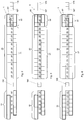
- Each stand 25, 26, 27, 26', 27' of the second section 20 comprises three rolling rollers having rotation axes which are arranged at 120° from one another. Moreover, the rotation axes of the rollers for each stand 25, 26, 27, 26', 27' of the second section 20 are rotated by 180° with respect to the rotation axes of an adjacent stand. More in details, the position of the axes of any one stand with respect to those of an adjacent stand, is assessed with respect to a vertical direction 150 which is orthogonal to the support surface 300. In this regard, figures 1a and 1b are schematized for the purposes of showing such an arrangement.
- figure 1a schematizes the arrangement of the axes of rollers A, B, C in a stand taken as a reference
- figure 1b schematizes the arrangement of rollers A', B', C' of an adjacent stand.
- adjacent means a stand which may be upstream or downstream with respect to the stand taken as a reference with respect to the feeding direction 200.
- At least one rolling stand of the second section 20 comprises a motorized roller having a vertical rotation axis.
- a roller is motorized through a drive shaft, which also has a vertical axis.
- the use of one or more stands with a vertical axis motorized roller advantageously simplifies the replacement of the stands of the second section 20, thus drastically decreasing the times related to this operation.
- the second section 20 of rolling mill 1 comprises at least one fixed rollers stand, this expression meaning a stand in which the position of the rollers (i.e. of their rotation axes) is not adjustable/modifiable with respect to the rolling axis 100.
- Said at least one fixed rollers stand comprises mechanical transmission means configured to transmit the motion from one of said rollers, preferably from the vertical axis motorized roller, to the other two rollers of the stand.
- Figures 9 and 10 commented on below show a possible embodiment of a fixed rollers stand of a rolling mill according to the invention.
- the rolling mill 1 comprises a first series of fixed rollers stands 25', 25 (hereinafter also indicated with the expression first stands 25' 25) arranged in sequence along said rolling axis 100 starting from the inlet side 20' of the second section 20. Therefore, the inlet stand 25' is a fixed rollers stand.
- the rolling stands 15', 15, 15" of the first section 10 of the rolling mill 1 have three rolling rollers having rotation axes which are arranged at 120° from one another.
- the rotation axes of the inlet stand 25' of the second section 20 are rotated by 180° with respect to the rotation axes of the rollers of the outlet stand 15" of the first section 10.
- the position of the axes is always assessed with respect to the vertical reference direction 150.
- the position of the rollers of the outlet stand 15" of the first section 10 with respect to the rollers of the inlet stand 25' of the second section 20 follows what is shown in the schematizations in figures 1a and 1b .
- the rollers of the rolling stands 15', 15, 15" of the first section 10 advantageously are aligned with the rollers of the rolling stands 25', 25, 26, 27, 26', 27' of the second section 20.
- the thickness tolerances may be improved to the benefit of the improved quality of the final product.
- each fixed rollers stand 25', 25 comprises a vertical axis motorized roller 31 and mechanical transmission means configured to transmit the motion from such a motorized roller to the other two rollers of the stand.
- said vertical axis roller is motorized through a vertical axis drive shaft for each fixed rollers stand 25', 25.
- the second section 20 of the rolling mill 1 preferably comprises at least one adjustable rollers stand operatively positioned downstream of the fixed rollers stand or stands 25', 25.
- the expression “adjustable rollers stand” means a stand in which the distance of the rollers from the rolling axis 100 can be adjusted in order to vary the rolling conditions and implement a corresponding variation in diameter.
- said at least one adjustable rollers stand also comprises a vertical axis motorized roller.
- the rolling mill 1 comprises a series of adjustable rollers stands 26, 27, 26', 27' (or second stands 26, 27, 26', 27') arranged in sequence along the rolling axis 100 downstream of the fixed stands 25', 25, again with respect to the feeding direction 200.
- each of the second stands 26, 27, 26', 27' comprises a first motorized vertical axis roller 34, 34'.
- the second section 20 also comprises a dummy stand 28, this expression meaning a stand in which no thickness reduction or deformation of the hollow body is performed, and in which the roller or rollers present have the only function of carrying and guiding the piece along the rolling direction 100.
- a dummy stand 28 can be arranged for example, between a fixed rollers stand and an adjustable rollers stand or alternatively downstream of the adjustable rollers stand according to the plant engineering needs.
- Figures 1 to 4 are diagrams related to the possible configuration of a rolling mill 1 according to the present invention.
- the first section 10 of the rolling mill 1 has the same configuration substantially defined by six rolling stands 15', 15, 15", each having three rollers as indicated above.
- the second section 20 overall defines sixteen positions, each of which is destined to be occupied by a rolling stand (with fixed or adjustable rollers) or alternatively by a dummy stand.
- thirteen of the sixteen positions are configured so as to accommodate a fixed rollers stand or alternatively a dummy stand, while the last three positions are instead configured to accommodate any type of stand (fixed rollers - adjustable rollers - dummy stand).
- the second section 20 comprises a first stretch 21 defining a first series of lodging positions which may be occupied by a fixed stand 25', 25 or alternatively by a dummy stand 28.
- the second section 20 also comprises a second stretch 22 defining a second series of positions which may be occupied by fixed stands, adjustable stands or dummy stands, wherein the adjustable stands also may be operatively connected in a group (60, 62).
- the second section 20 provides an equal number of fixed stands and more in details provides fourteen fixed stands 25', 25 arranged in sequence starting from the inlet side 20'.
- the last two positions of the second section 20 are instead occupied by two adjustable rollers stands 26, 27.
- the latter are connected to each other so as to form a single group 60 of two adjustable rollers stands wherein at least one motorized roller of one of the stands is operatively connected to a roller of the other stand.
- a group 60 is also indicated with the expression "even bi-stand 60" where "even” means that the two stands 26, 27 defining such a bi-stand are used when the overall number of rolling stands is even.
- the second section 20 provides thirteen fixed stands 25', 25 which occupy thirteen positions starting from the inlet side 20'.
- the first two positions of the second stretch 22 (corresponding to the 14 th and 15 th positions of the second section 20) are occupied by another group 62 of adjustable stands 26', 27' indicated hereinbelow with the expression "odd bi-stand 62", where the term “odd” means that the two stands 26' and 27' which define such a bi-stand are used when the overall number of rolling stands is odd.
- the last position of the second stretch 22 instead is occupied by a dummy stand 28.
- the even bi-stand 62 is conceptually and functionally similar to the odd bi-stand 60 because a motorized roller of one of the stands 26' or 27' is operatively connected to a roller of the other stand. Indeed, the same technical solutions in terms of motion definition and transmission between the various parts preferably are provided for the bi-stands (even 60 and odd 62). It can be noted that both the bi-stands (even 60 and odd 62) are actuated through actuation means, typically drive shafts, installed in predetermined positions along the second stretch 22 of the second section 20.
- actuation means typically drive shafts
- the odd bi-stand 62 has a configuration which in fact mirrors that of the even bi-stand 60 with respect to a vertical plane containing the rolling axis 100.
- the configuration of the second section 20 in terms of the number and position of fixed stands 25', 25 and of dummy stands 28 in the first stretch 21 and in terms of the position of the adjustable/fixed/dummy stands in the second stretch 22, may vary according to process needs.
- the selection of the number of stands used and the related arrangement in the rolling mill 1 substantially depend on the reduction of the diameter which occurs in the calibration step (second section 20).
- first stretch 21 of section 20 in fact does not require any foundation below the support surface 300.
- foundations are always limited to the second stretch 22 which defines a significantly lower number of positions than the number of positions defined by the first stretch 21.
- the rolling without mandrel is mainly performed through fixed rollers stands.
- a first speed meter 166 for measuring the feeding speed of the hollow body between the two sections 10, 20 of the rolling mill 1 in order to control the speed along the second section 20.
- the rolling mill 1 further comprises a second speed meter 167 operatively arranged at the outlet of the second section 20.
- the rolling mill 1 further comprises a thickness gauge 178 also arranged at the outlet of the second section 20. It can be noted that the in line configuration of the rolling mill 1 according to the invention advantageously allows at least one of the thickness gauges required in traditional plants comprising two independent rolling lines, one upstream of the heating furnace and the other downstream of the final calibrator, to be eliminated.
- Figure 5 and figure 6 are a side view of the second section 20 of a rolling mill 1 according to the diagram in figure 1 and according to the diagram in figure 2 , respectively.
- the arrangement of the fixed stands 25', 25 and of the even bi-stand 60 forming the second section 20 can be noted in figure 5 .
- the arrangement of the fixed stands 25', 25, the odd bi-stand 62, the dummy stand 28 forming the second section 20 instead can be noted in figure 6 .
- the second stretch 22 of the second section 20 allows the position of the adjustable stands to be varied using an even bi-stand 60 or alternatively an odd bi-stand 62 according to operating needs.
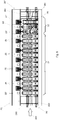
- Figure 7 is a plan view of the second section 20 of the rolling mill shown in figure 5 .
- Figure 7 shows the even bi-stand 60 and the actuation means (drive shafts 30A, 30B, 30C) installed in the second stretch 22.
- the bi-stand 60 is configured to interact with two drive shafts 30A, 30B (hereinafter indicated with “right-hand drive shaft 30A” and “left-hand drive shaft 30B") arranged on opposite sides with respect to the rolling axis 100.
- the right-hand drive shaft is operatively associated with the second-last position of the second stretch 22, while the left-hand drive shaft is associated with the last position of the same stretch.
- the second section 20 comprises first releasing thrust cylinders 290 positioned on the inlet side 20' and second locking thrust cylinders 291 positioned on the outlet side 20" of the second section 20.
- the second cylinders 291 exert an axial thrust on the stands 25', 25, 26, 27, 26', 27' and dummy stands 28 in a direction opposite to direction 200 in order to compact them along the rolling direction and lock them axially.
- the first cylinders 290 exert an axial thrust on the stands 25', 25, 26, 27, 26', 27 and dummy stands 28 in a direction concordant to direction 200 in order to release them once they have been axially locked, in order to allow the stand-replacement operations.
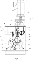
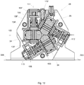
- Figure 8 is a view according to the sectional plane VIII-VIII in figure 5 .
- Figure 8 shows the fixed inlet stand 25' frontally, i.e. from an observation point on the rolling axis 100 downstream of the first section 10.
- stand 25' is accommodated in a first lodging space 81 defined by a fixed structure 8 which extends vertically (vertical direction 150), simultaneously defining a horizontal plane 300 on which the stand itself lies.
- Structure 8 further comprises a support plane 82 which extends parallel to the support surface 300.
- An actuation device 130 of a vertical axis drive shaft 30 is installed above the support plane 82.
- the vertical axis drive shaft is configured to be removably connected to a first vertical axis roller 31 of stand 25'.
- a coupling/releasing device 45 of the vertical control drive shaft 30 which is substantially installed in a second lodging space 83 defined between the first space 81 and the support plane 82.
- the coupling/releasing device is configured to move the vertical drive shaft 30 between a coupled position, in which the drive shaft is operatively connected to the first roller 31, and a released position, in which the drive shaft instead is disconnected from the roller to allow for example, the replacement of stand 25'.
- the actuation device 130 of drive shaft 30 comprises a motor 131 and a mechanical reducer 132.
- the latter is interposed above the support plane 82, between motor 131 and the vertical drive shaft 30.
- motor 131 is installed so as to have a vertical axis, i.e. so as not to emerge laterally from structure 8.
- the space adjacent to the sides 8', 8" of the structure advantageously remains free to be exploited within the scope of the stand-replacement operation, as described below (with reference to figures 17 and 18 ).
- the plan view in figure 7 allows to note how each stand of the section itself is rotated by 180° with respect to an adjacent stand, according to the above-described principle.
- the coupled position 125 of the vertical drive shaft related to the fixed rollers inlet stand 25' which is rotated by 180° with respect to the coupled position 125' of the vertical drive shaft of a second stand 25 immediately adjacent to the inlet one.
- the same principle applies to the coupled position 125" of a third stand adjacent to the second one 25, and so on. It can be noted that such a relationship is kept for all the positions defined by the second section 20, therefore also for the second stretch 22 of the section itself.
- Figures 9 and 10 are views related to the embodiment of a fixed stand 25 according to the invention, which may be positioned in any position of the first stretch 21 of the second section 20 or also in a position of the second stretch 22.
- stand 25 comprises a body 70 which extends between two plates 70' and which carries the rollers 31, 32, 33.
- the latter have a configuration which in itself is known and they keep a fixed position, that is not adjustable with respect to the rolling axis 100. Therefore, stand 25 always achieves the same rolling condition, i.e. the same reduction in diameter.
- body 70 and the two plates 70' are configured so as to define an operating recess 70" in which there are accommodated three rolling rollers 31, 32, 33, the mutual position of which in fact defines the rolling axis 100.
- the first roller 31 has a vertical axis 101 (or first axis 101) defined by a central element 71 onto which the roller itself is keyed.
- the central element 71 is connected on one side to a first lateral element 71', and on the other side to a second lateral element 71", which are opposite to each other with respect to the first roller 31. More in details, the central element 71 is connected to each of the two lateral elements 71', 71" through an axial connection (e.g. axial teeth or grooved profiles) so that the three elements 71, 71', 71" rotate in a synchronous manner.
- the first lateral element 71' comprises a free end 72 which may be connected to a vertical drive shaft 30, as shown in figure 8 , or to another functionally equivalent actuating means.
- the three elements 71, 71', 71" overall define a first set of elements 71-71'-71" which carries and allows the rotation of the first roller 31.
- a connector pin 74 arranged longitudinally inside the three hollow elements 71, 71', 71" to avoid the removal thereof.
- first supports 75 arranged in various positions along the first axis 101 to allow the rotation of the elements of the set of elements 71, 71', 71". It is worth noting that the axial connection between the central element 71 and the two lateral elements 71', 71" is removable in order to allow an easy extraction of the first roller 31 from the operating recess defined by the body 70 of stand 25.
- a second set of elements 76-77 defined by an axially connected central element 76 (again through an axial coupling) and two lateral elements 77 rotating on second supports 75'.
- the second set of elements defines a second rotation axis 102 for the second roller 32, inclined by 120° with respect to the first rotation axis 101.
- a third set of elements (indicated with numerals 76', 77'), which is constructively equivalent to the second set of elements 76-77, carries the third roller 33 thus defining a third rotation axis 103 inclined by 120° with respect to the vertical axis 101 and with respect to the second axis 102.
- the first roller 31 is also operatively connected to the second roller 32 and to the third roller 33 through drive means configured so that all the rollers are actuated by the control drive shaft 30 connected to the first set of elements 71, 71', 71" related to the first roller 31.
- the transmission means comprise two conical driving gears 79, 79', each keyed onto one of the lateral elements 71', 71" of the first set of elements 71-71'-71".
- a first conical driving gear 79 meshes with a first driven gear 78 keyed onto the lateral element 77 of the second set of elements 76-77 closest to the vertical rotation axis 101 of the first roller 31.
- the second conical driving gear 79 meshes with a second driven gear 78' keyed onto the lateral element 77' of the third set of elements 76'-77' closest to the vertical rotation axis 101 of the first roller 31.
- the transmission means are therefore configured to achieve a synchronous rotation of the three rollers 31, 32, 33. Therefore, the conical driving gears 79, 79' mesh with the corresponding driven gears 78, 78' with a transmission ratio equal to 1.
- stand 25 is provided with a cooling system of roller 31, 32, 33 comprising an intake 174, which may be connected to an external circuit, and a cooling circuit 170 comprising three end nozzles 177, each of which being configured to eject coolant close to one of the three rolling rollers 31, 32, 33.
- structure 8 of the second section 20 also comprises a connection device 145 for connecting/disconnecting the above intake 174 of stand 25 to/from an external supply circuit.
- a connection device 145 is installed on the side of the coupling/releasing device 45 of the vertical drive shaft 30.
- Figures 11 to 16 are related to a group of adjustable rollers stands.
- such drawings show an even bi-stand 60 which may be installed in the second stretch 22 of the second section 20, for example in the configuration shown in figures 1 and 3 .
- the technical solutions for the even stand 60 described below are to be considered valid, mutatis mutandis, also for the odd stand 62.
- the technical solutions described below for the first stand 26 and for the second stand 27 of the even bi-stand 60 correspond to that provided for the second stand 27' and for the first stand 26' of the odd bi-stand 62, respectively, from a constructional viewpoint (in terms of components, definition of the motion, position of the rollers, etc.).
- the even bi-stand 60 comprises a first stand 26 and a second stand 27 adjacent to the first stand 26.
- the first stand 26 comprises at least one drive roller, that is a roller which is motorized directly through an actuating means, preferably through a control drive shaft.
- bi-stand 60 comprises a transmission device which operatively connects said at least one drive roller of the first stand 26 with a driven roller 34' of the second stand 27 so that such a driven roller 34' is motorized, even though in an indirect manner, by the same actuating means which motorizes the drive roller.
- bi-stand 60 preferably comprises three transmission devices, each of which operatively connects a motorized roller of one of the two stands 26 or 27, which acts as a "drive roller", to a roller of the other stand 27 or 26 which becomes a "driven roller".
- the actuation of the six rollers of the bi-stand overall is achieved only through three control drive shafts, each of which connected to the rollers of the stands 26, 27 which act as "drive rollers”.
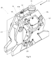
- FIG 11 is a perspective view of bi-stand 60 according to the invention.
- the two stands 26, 27 which form bi-stand 60 are integrated in a single structure defined by a body 60' which is axially closed by two plates 60".
- Body 60' and the plates 60" define an operating recess 61 in which there are arranged the rollers 34, 35, 36 of the first stand 26 and the rollers 34', 35', 36' of the second stand 27.
- Body 60' also defines the seats for the elements which allow the rotation of the rollers and the position adjustment thereof.
- figures 12 and 13 are sectional views which allow the spatial arrangement of the rollers 34, 35, 36, 34', 35', 36' of the two stands 26, 27, respectively, to be noted.
- the first roller 34 in the first stand 26 has a vertical rotation axis 111 (or first axis 111), while the second roller 35 rotates about a second axis 112 inclined by 120° with respect to the first axis 111.
- the second roller 35 is operatively positioned above a reference plane 105 passing through the rolling axis 100 and parallel to the support surface 300.
- the third roller 36 rotates about a third axis 113 inclined by 120° with respect to the first axis 111.
- the third roller 36 is operatively positioned below said reference plane 105.
- the three rollers 34', 35', 36' in the second stand 27 have a position which is rotated by 180° with respect to the position of the rollers 34, 35, 36 of the first stand 26.
- the second roller 35' of the second stand 27 is operatively positioned above the reference plane 105, but the rotation axis 112' thereof is parallel to the rotation axis 113 of the third roller 36 of the first stand 26.
- the third roller 36' of the second stand 27 is operatively positioned below the reference plane 105 and the rotation axis 113' thereof is parallel to the rotation axis 112 of the second roller 35 of the first stand 26.
- the rotation axis 111 of the first roller 34 of the first stand 26 instead has a position which mirrors the rotation axis 111' of the first stand 27 with respect to a vertical plane containing the rolling axis 100.
- the first roller 34' is keyed onto a central bush 134 axially connected (for example, through a cogged coupling) to a first sleeve 135 and to a second sleeve 136.
- a longitudinal pin 137 is arranged inside the central bush 134 and the sleeves 135, 136 to avoid the removal of the set of elements 134-135-136 thus formed, according to a principle already described above.
- the second stand 27 comprises a transmission element 191 which may be connected to an external actuating means such as e.g. a vertical axis drive shaft.
- the transmission element 191 rotates with respect to the body 60' of stand 60 by means of suitable supports 192. It can be noted that the transmission element 191 establishes a fixed connection position of the vertical drive shaft or in any case, of the actuating means used.
- the second stand 27 further comprises a joint 195 configured to transmit the motion from the transmission element 191 to the set of elements 134-135-136 which carry the first roller 34'.
- joint 195 connects an end part 196 of the transmission element 191 with a connection element 197 keyed/screwed onto a portion of the second sleeve 136 of the set of elements 134-135-136.
- the position of the first roller 34' is adjustable through an adjusting device (described below), while the position of the transmission element 191 is fixed with respect to the body 60' of bi-stand 60.
- the rotation axis of the first roller 34' may take on an eccentric position with respect to the rotation axis of the transmission element 191 defined by the supports 192.
- Joint 195 therefore has the specific function of keeping the set of elements 134-135-136, and therefore the first roller 34', connected to the first transmission element 191 also after the variation of the position of the rotation axis 111' of the first roller 34'.
- the even bi-stand 60 comprises a first transmission device 91 which operatively connects the first roller 34 of the first stand 26 to the first roller 34' of the second stand 27.
- One embodiment of the transmission drive device 91 is shown in the sectional view in figure 15 .
- the first device 91 comprises a first cogged wheel 95 and a second cogged wheel 95' having parallel axes, which mutually mesh with each other.
- the first cogged wheel 95 meshes a cogged portion of the transmission element 191 which is connected to the set of elements 134-135-136 by means of the oscillating joint 195, which set of elements is functional to the first roller 34' of the second stand 27.
- the second cogged wheel 95' instead meshes with a cogged portion of a further transmission element 191' related to the first stand 26.
- a further transmission element 191' may be connected to a set of elements 134'-135'-136' through a corresponding joint 195' according to the same principle described above.
- the rotation of the transmission element 191 is transferred through the two cogged wheels 95, 95' to the other transmission element 191', with a transmission ratio preferably equal to 1.
- the two transmission elements 191, 191' and the corresponding set of elements 134-135-136, 134'-135'-136' rotate at the same speed.
- various speeds may be obtained.
- the plan view in figure 14 shows the transmission element 191, to which a first vertical control drive shaft 30' is preferably connected, as also shown in figure 16 .
- structure 8 of the second section 20 comprises a coupling/releasing device 45' of the first drive shaft 30'.
- the latter is actuated through a corresponding actuation device 130' arranged above the support plane 82 of structure 8 according to a similar solution to that described in the comments on the fixed stand 25'.
- the transmission element 191' which is functional to the first roller 34 of the first stand 26 is not connected to any external actuation due to the effect of the transmission device 191.
- the even bi-stand 60 comprises a second transmission device which operatively connects the second roller 35 of the first stand 26 to the third roller 36' of the second stand 27.
- the even bi-stand 60 further comprises a third transmission device which operatively connects the third roller 36 of the first stand 26 to the second roller 35' of the second stand 27.
- the second transmission device and the third drive device have an entirely similar configuration to that of the first device 91 described above.
- the use of the three transmission devices indicated above allows the number of drive shafts to be reduced to three, and accordingly the number of motors required for moving the six rollers of the even bi-stand 60. This results in a reduction of the plant manufacturing and management costs.
- the second transmission device is actuated through a second drive shaft 30" which is connected to a second transmission element 198 (indicated in figures 11 and 12 ) which is functional to the third roller 36 of the first stand 26.
- the third transmission device instead is actuated through a third drive shaft 30''' which is connected to a further transmission element 199 (indicated in figure 13 ) which is functional to the third roller 36' of the second stand 27.
- the term "functional" means that one of the transmission elements 198, 199, 191, 191' mentioned is connected by means of a joint to a corresponding set of elements which supports a corresponding roller, according to the principles described above.
- the second transmission device and the third transmission device are actuated through a corresponding inclined drive shaft 30", 30''' which meshes in the corresponding transmission element 198, 199 in a position which is very close to the support surface 300 and in any case is below the reference plane 105 indicated above.
- This arrangement is clearly visible in the sectional view in figure 18 in which, in addition to the two inclined drive shafts 30", 30''', the configuration is shown of the foundations of the rolling mill 1 obtained for the second stretch 22 of the second section 20.
- the inclined drive shafts 30", 30''' are actuated through actuation means 155 in themselves known.
- the foundations of the second stretch 22 have a more contained height with respect to the foundations of a traditional rolling section with three-rollers stands. It can also be noted that the mutual arrangement of the three drive shafts 30', 30", 30''' advantageously allows a bilateral type stand-replacement plant to be made, as described below.
- bi-stand 60 comprises a first adjusting mechanism of the position of the rollers 34, 35, 36 of the first stand 26 and a second adjusting mechanism of the position of the rollers 34', 35', 36' of the second stand 27.
- the two adjusting mechanisms advantageously have the same configuration. Therefore, only the second adjusting mechanism related to the second stand 27 is hereinbelow described for simplicity, referring to that shown in figure 13 .
- the second adjusting mechanism comprises, for each of the rollers 34', 35', 36', a pair of lateral bushes each of which keyed onto one of the lateral sleeves which define the set of elements carrying the corresponding roller according to the principles disclosed above.
- a first lateral bush 171 and a second lateral bush 172 are mounted on the first sleeve 135' and on the second sleeve 136', respectively, which sleeves define the set of elements 134', 135', 136' which carries the second roller 35'.
- the two lateral bushes 171, 172 are mounted on the corresponding sleeves 136', 135' through suitable bearings 182.
- the second adjusting mechanism comprises a substantially arc-shaped connection element 173, which connects the two lateral bushes 171, 172 so that the latter remain operatively connected.
- Each of the two lateral bushes 171, 172 comprises a cogged portion which meshes a cogged portion of a corresponding lateral bush 171', 172' mounted on a lateral sleeve related to a set of elements which carries another roller of the stand.
- a cogged portion of the first bush 171 meshes with a cogged portion of a corresponding lateral bush 171' mounted on the second lateral sleeve 136 of the set of elements 134-135-136 which carries the first roller 34.
- a cogged portion of the second bush 172 instead meshes with a cogged portion of a further lateral bush 172' mounted on a lateral sleeve 135" of the corresponding set of elements 134"-135"-136" which carries the third roller 36'.
- the adjusting mechanism comprises an adjusting pinion 175 which may be actuated through an external device 166 (indicated in figure 16 ) mounted on the support structure 8 of the second section 20 of the rolling mill.
- the adjusting pinion 175 rotates about a vertical rotation axis (parallel to the axis of the first roller 34') and is operatively connected to the assembly formed by the two lateral bushes 171, 172 and by the connection element 173 so that the rotation of pinion 175 causes a rotation of such an assembly 171-172-173 about an axis which is eccentric to the rotation axis 112' of the second roller 35'.
- the rotation of the assembly of elements 171-172-173 causes a corresponding eccentric rotation of the set of elements 134'-135'-136' and accordingly, of the second roller 35' itself, which varies its position with respect to the rolling axis 100.
- the eccentric rotation of the set of elements 134'-135'-136' is also transferred to the set of elements carrying the other rollers 34', 36' due to the effect of the meshing between the various lateral bushes 171, 172, 171', 172' described above. Therefore, the other rollers 34'. 36' also vary their position with respect to the rolling axis 100 in corresponding manner to the second roller 35'.
- the external mechanism 166 configured for actuating the adjusting pinion 175 is preferably installed in the second space 83 defined by structure 8.
- the external mechanism 166 may be removably connected to the corresponding pinion 175, which emerges with respect to the body 60' of bi-stand 60.
- the first adjusting mechanism of the first stand 26 of bi-stand 60 has a configuration corresponding to that described above for the second adjusting mechanism, as also shown by the comparison between figures 12 and 13 . It can be noted that the two adjustments of the radial positions of the rollers of the stands 26, 27 are independent, since they may be actuated by means of independent pinions 175 and 175'.
- the second section 20 comprises a first platform 51 and a second platform 52 which extend longitudinally on opposite sides 8', 8" of structure 8.
- Each of such platforms 51, 52 is configured to carry a replacement stand 25A, an even replacement bi-stand 60A or an odd replacement bi-stand 62A intended to replace a stand or bi-stand of the second section 20.
- the two platforms 51, 52 are also configured to carry stand 25', 25 or bi-stand (even 60 or odd 62) of the second section 20 which is replaced by the replacement stand or bi-stand.
- the second section 20 comprises a shifting device 299 configured to push at least one replacement stand/bi-stand 25A, 60A, 62A arranged on one of the platforms (e.g.
- first platform 51 against a stand/bi-stand 25, 60, 62 to be replaced up to the latter being completely positioned on the opposite platform (second platform 52). More in details, the shifting device 299 pushes the stands along a direction 109 which is substantially orthogonal to said rolling axis 100.
- Figures 17 and 18 are further sectional views showing the replacement principle of the fixed rollers stands 25', 25 and/or of the adjustable rollers bi-stands 60, 62.
- figure 17 shows the replacement of a fixed rollers stand 25, while figure 18 refers to the replacement of an even bi-stand 60.
- the first platform 51 represents a loading platform in which the replacement stands 25A are loaded
- the second platform 52 represents an unloading platform from which the stands to be replaced are picked once the replacement operation is complete.
- the movement of the fixed stands 25 to and from the platforms 51, 52 is performed through loading cranes or functionally equivalent means.
- This "aerial" movement is mainly allowed by the configuration given to the fixed stands whereby all the rollers are actuated through a vertical axis drive shaft.
- the configuration of the support structure 8, hence the space adjacent to the longitudinal sides 8', 8", is also free and the installation selections described above (for example, “vertical” actuations above the support plane 82 of structure 8) allow the aerial movement of the fixed stands and therefore allow the reduction of the stand replacement times to just a few minutes.
- the replacement of one fixed rollers stand 25 includes a first step in which a replacement stand 25A is keyed onto the first platform 51 (arrow 401) through a crane.
- the replacement stand 25A is pushed by the shifting device 299 against the stand to be replaced 25 up to it occupying the position on the second platform 52.
- the stand 25 to be replaced is raised, always through a crane, and moved away from the second section 20 (arrow 402).
- the replacement principle of the stand replacement combined with the possibility of using a hoisting crane in fact avoids designing and manufacturing traditional replacement carriages and/or traditional movable tables used to replace the stands in traditional rolling mills characterized by having horizontal drive shafts.
- FIG 18 shows how the above-described replacement principle of the fixed stands advantageously also may be used for movable stands and in particular, for replacing the even bi-stand 60 described above. It is understood that the same principle may be applied to an odd bi-stand 62. Indeed, a replacement bi-stand (even 60A or odd 62A) may be easily lowered onto the first platform 51 (arrow 401), pushed by the shifting device 299 against a corresponding bi-stand (even 60 or odd 62) to be replaced positioned in the second section 20. Once the bi-stand (even 60 or odd 62) to be replaced occupies the second platform 52, it may be picked and moved away from the second section (arrow 402).
- the replacement principle may be applied due to the effect of the configuration of the bi-stand itself and due to the fact that the drive shafts 30', 30" inclined with respect to the vertical axis are operatively positioned below the horizontal reference plane 105 (indicated in figure 13 ) and in position close to the support surface 300 of the stands 25, 26, 27 of the second section 20.
- the actuation means 155 of the inclined drive shafts 30", 30''' are configured so as to move the same between an operating position, in which they are operatively connected to the bi-stand, and a withdrawn position in which the drive shafts 30", 30''' are completely below the support surface 300, thus allowing the movement of the stands along the shifting direction 109.
- the rolling mill according to the invention allows the above tasks and objects to be completely achieved.
- the configuration of the rolling mill allows the dimensions and costs of the system to be contained, and also all the problems of traditional systems generated by the presence of intermediate heating furnaces to be eliminated.
- the configuration provided for the second section of the rolling mill and the structure provided for the fixed rollers stands and for the adjustable rollers stands allow the manufacturing costs of the foundations to be minimized while simultaneously greatly reducing the costs related to the actuations of the stands.
Landscapes
- Engineering & Computer Science (AREA)
- Mechanical Engineering (AREA)
- Metal Rolling (AREA)
- Transmission Devices (AREA)
- Crushing And Grinding (AREA)
- Buildings Adapted To Withstand Abnormal External Influences (AREA)
Priority Applications (1)
| Application Number | Priority Date | Filing Date | Title |
|---|---|---|---|
| PL16810026T PL3365119T3 (pl) | 2015-10-23 | 2016-10-21 | Walcownia wielostanowiskowa dla korpusów o kształcie drążkowym, zawierająca trzy stanowiska o zmechanizowanych wałkach |
Applications Claiming Priority (2)
| Application Number | Priority Date | Filing Date | Title |
|---|---|---|---|
| ITUB2015A005314A ITUB20155314A1 (it) | 2015-10-23 | 2015-10-23 | Laminatoio multigabbia per corpi astiformi comprendente gabbie a tre rulli motorizzati |
| PCT/IB2016/056328 WO2017068533A1 (en) | 2015-10-23 | 2016-10-21 | Multi-stand rolling mill for rod-shaped bodies comprising three motorized-rollers stands |
Publications (2)
| Publication Number | Publication Date |
|---|---|
| EP3365119A1 EP3365119A1 (en) | 2018-08-29 |
| EP3365119B1 true EP3365119B1 (en) | 2020-01-01 |
Family
ID=55359651
Family Applications (1)
| Application Number | Title | Priority Date | Filing Date |
|---|---|---|---|
| EP16810026.1A Revoked EP3365119B1 (en) | 2015-10-23 | 2016-10-21 | Multi-stand rolling mill for rod-shaped bodies comprising three motorized-rollers stands |
Country Status (8)
| Country | Link |
|---|---|
| US (1) | US20180304327A1 (ja) |
| EP (1) | EP3365119B1 (ja) |
| JP (1) | JP2018531154A (ja) |
| CN (1) | CN108367322A (ja) |
| IT (1) | ITUB20155314A1 (ja) |
| PL (1) | PL3365119T3 (ja) |
| RU (1) | RU2687522C9 (ja) |
| WO (1) | WO2017068533A1 (ja) |
Families Citing this family (5)
| Publication number | Priority date | Publication date | Assignee | Title |
|---|---|---|---|---|
| DE102018207908A1 (de) * | 2018-05-18 | 2019-11-21 | Sms Group Gmbh | Streckreduzierungswalzwerk mit verbesserter Durchmesser- und Wanddickentoleranz |
| DE102018219874B4 (de) | 2018-11-20 | 2020-08-20 | Sms Group Gmbh | Schnellwechselbares Walzgerüst |
| IT202000028772A1 (it) * | 2020-11-27 | 2022-05-27 | Danieli Off Mecc | Laminatoio calibratore e/o riduttore per corpi astiformi |
| CN114453425A (zh) * | 2021-12-31 | 2022-05-10 | 太原重工股份有限公司 | 一种采用顶部定位的双侧换辊连轧管机装置 |
| KR102642360B1 (ko) * | 2023-09-08 | 2024-02-29 | 주식회사 태오 | 가변형 3롤 기반의 알루미늄 압연 시스템 |
Citations (18)
| Publication number | Priority date | Publication date | Assignee | Title |
|---|---|---|---|---|
| DE3825746A1 (de) | 1988-07-26 | 1990-02-01 | Mannesmann Ag | Walzstrasse zum streckreduzieren von rohren |
| JPH05138210A (ja) | 1991-11-22 | 1993-06-01 | Mitsubishi Heavy Ind Ltd | マンドレルミル |
| JPH0588704U (ja) | 1992-04-30 | 1993-12-03 | 新日本製鐵株式会社 | マンドレルミルにおけるエキストラクター |
| JPH07314013A (ja) | 1994-03-29 | 1995-12-05 | Sumitomo Metal Ind Ltd | 3ロールマンドレルミルの圧延装置列 |
| US6041635A (en) | 1995-11-29 | 2000-03-28 | Demag Italimpianti S.P.A. | Unit for rolling pipes on a mandrel |
| US20010027674A1 (en) | 2000-03-28 | 2001-10-11 | Heinrich Potthoff | Rolling unit for a rolling mill for rolling or sizing metal pipes, bars or wires |
| DE10015285A1 (de) | 2000-03-28 | 2001-10-18 | Kocks Technik | Walzstraße zum Walzen von metallischen Rohren, Stäben oder Drähten |
| EP1449597A2 (de) | 2003-02-20 | 2004-08-25 | SMS Meer GmbH | Walzgerüst zum Walzen von langgestrecktem Gut |
| WO2007014911A1 (en) | 2005-07-29 | 2007-02-08 | Danieli & C. Officine Meccaniche S.P.A. | Rolling mill with stands with three adjustable rolls |
| EP1764167A1 (de) | 2005-09-20 | 2007-03-21 | SMS Meer GmbH | Verfahren und Walzwerk zur Herstellung eines nahtlosen Rohres |
| US7424816B2 (en) | 2002-09-30 | 2008-09-16 | Kocks Technik Gmbh & Co. | Roll stand for rolling bar-shaped or tubular stock |
| WO2009141417A1 (de) | 2008-05-21 | 2009-11-26 | Grillo Zinkoxid Gmbh | Verfahren zur herstellung von alkalimetall-dotiertem nanoskaligem zinkoxid mit variablem dotierungsgehalt |
| JP2010149190A (ja) | 2010-02-05 | 2010-07-08 | Sumitomo Metal Ind Ltd | 継目無管の圧延装置および圧延制御方法 |
| JP2011520617A (ja) | 2008-05-22 | 2011-07-21 | ダニエリ アンド シー.オフィチネ メッカニチェ ソシエタ ペル アチオニ | 圧延機スタンド及び棒状体を長手方向に圧延するための関連した圧延機 |
| DE102010052084B3 (de) | 2010-11-16 | 2012-02-16 | V&M Deutschland Gmbh | Verfahren zur wirtschaftlichen Herstellung von nahtlos warmgewalzten Rohren in Rohrkontiwalzwerken |
| EP2008732B1 (en) | 2006-03-29 | 2013-10-30 | Nippon Steel & Sumitomo Metal Corporation | Cold finish seamless steel pipe for drive shaft and method for producing the same |
| WO2014056969A1 (en) | 2012-10-10 | 2014-04-17 | Danieli & C. Officine Meccaniche S.P.A. | Rolling stand with three working rolls |
| US20150121982A1 (en) | 2012-07-24 | 2015-05-07 | Nippon Steel & Sumitomo Metal Corporation | Manufacturing method of seamless metal pipe, mandrel mill, and auxiliary tool |
Family Cites Families (6)
| Publication number | Priority date | Publication date | Assignee | Title |
|---|---|---|---|---|
| SU997865A1 (ru) * | 1981-09-10 | 1983-02-23 | Всесоюзный ордена Ленина научно-исследовательский и проектно-конструкторский институт металлургического машиностроения | Двухклетевой блок редукционного стана |
| EP0988120B1 (de) * | 1997-06-05 | 2002-08-28 | V & M Deutschland GmbH | Verfahren und einrichtung zur erfassung des ist-zustandes eines heissen rohres |
| IT1298750B1 (it) * | 1998-03-18 | 2000-02-02 | Demag Italimpianti Spa | Laminatoio a bracci oscillanti,destinato in particolare ma non esclusivamente alla laminazione di tubi senza saldatura |
| EP1854561B1 (en) * | 2005-02-22 | 2011-08-24 | Sumitomo Metal Industries, Ltd. | Process for producing seamless pipe |
| IT1392497B1 (it) * | 2008-12-30 | 2012-03-09 | Danieli Off Mecc | Laminatoio multigabbia, di tipo allungatore longitudinale, per corpi astiformi, comprendente gabbie a quattro rulli motorizzati, e procedimento per cambio gabbie |
| RU113182U1 (ru) * | 2011-09-20 | 2012-02-10 | Открытое акционерное общество "Электростальский завод тяжелого машиностроения" | Трехвалковая редукционно-калибровочная клеть |
-
2015
- 2015-10-23 IT ITUB2015A005314A patent/ITUB20155314A1/it unknown
-
2016
- 2016-10-21 RU RU2018118995A patent/RU2687522C9/ru active
- 2016-10-21 US US15/769,704 patent/US20180304327A1/en active Pending
- 2016-10-21 CN CN201680062086.8A patent/CN108367322A/zh active Pending
- 2016-10-21 PL PL16810026T patent/PL3365119T3/pl unknown
- 2016-10-21 EP EP16810026.1A patent/EP3365119B1/en not_active Revoked
- 2016-10-21 JP JP2018519054A patent/JP2018531154A/ja active Pending
- 2016-10-21 WO PCT/IB2016/056328 patent/WO2017068533A1/en active Application Filing
Patent Citations (20)
| Publication number | Priority date | Publication date | Assignee | Title |
|---|---|---|---|---|
| JPH02229603A (ja) | 1988-07-26 | 1990-09-12 | Mannesmann Ag | 管をストレッチレデューシングするための圧延路 |
| DE3825746A1 (de) | 1988-07-26 | 1990-02-01 | Mannesmann Ag | Walzstrasse zum streckreduzieren von rohren |
| JPH05138210A (ja) | 1991-11-22 | 1993-06-01 | Mitsubishi Heavy Ind Ltd | マンドレルミル |
| JPH0588704U (ja) | 1992-04-30 | 1993-12-03 | 新日本製鐵株式会社 | マンドレルミルにおけるエキストラクター |
| JPH07314013A (ja) | 1994-03-29 | 1995-12-05 | Sumitomo Metal Ind Ltd | 3ロールマンドレルミルの圧延装置列 |
| US6041635A (en) | 1995-11-29 | 2000-03-28 | Demag Italimpianti S.P.A. | Unit for rolling pipes on a mandrel |
| US20010027674A1 (en) | 2000-03-28 | 2001-10-11 | Heinrich Potthoff | Rolling unit for a rolling mill for rolling or sizing metal pipes, bars or wires |
| DE10015285A1 (de) | 2000-03-28 | 2001-10-18 | Kocks Technik | Walzstraße zum Walzen von metallischen Rohren, Stäben oder Drähten |
| US7424816B2 (en) | 2002-09-30 | 2008-09-16 | Kocks Technik Gmbh & Co. | Roll stand for rolling bar-shaped or tubular stock |
| EP1449597A2 (de) | 2003-02-20 | 2004-08-25 | SMS Meer GmbH | Walzgerüst zum Walzen von langgestrecktem Gut |
| WO2007014911A1 (en) | 2005-07-29 | 2007-02-08 | Danieli & C. Officine Meccaniche S.P.A. | Rolling mill with stands with three adjustable rolls |
| EP1764167A1 (de) | 2005-09-20 | 2007-03-21 | SMS Meer GmbH | Verfahren und Walzwerk zur Herstellung eines nahtlosen Rohres |
| EP1764167B1 (de) | 2005-09-20 | 2009-09-16 | SMS Meer GmbH | Verfahren und Walzwerk zur Herstellung eines nahtlosen Rohres |
| EP2008732B1 (en) | 2006-03-29 | 2013-10-30 | Nippon Steel & Sumitomo Metal Corporation | Cold finish seamless steel pipe for drive shaft and method for producing the same |
| WO2009141417A1 (de) | 2008-05-21 | 2009-11-26 | Grillo Zinkoxid Gmbh | Verfahren zur herstellung von alkalimetall-dotiertem nanoskaligem zinkoxid mit variablem dotierungsgehalt |
| JP2011520617A (ja) | 2008-05-22 | 2011-07-21 | ダニエリ アンド シー.オフィチネ メッカニチェ ソシエタ ペル アチオニ | 圧延機スタンド及び棒状体を長手方向に圧延するための関連した圧延機 |
| JP2010149190A (ja) | 2010-02-05 | 2010-07-08 | Sumitomo Metal Ind Ltd | 継目無管の圧延装置および圧延制御方法 |
| DE102010052084B3 (de) | 2010-11-16 | 2012-02-16 | V&M Deutschland Gmbh | Verfahren zur wirtschaftlichen Herstellung von nahtlos warmgewalzten Rohren in Rohrkontiwalzwerken |
| US20150121982A1 (en) | 2012-07-24 | 2015-05-07 | Nippon Steel & Sumitomo Metal Corporation | Manufacturing method of seamless metal pipe, mandrel mill, and auxiliary tool |
| WO2014056969A1 (en) | 2012-10-10 | 2014-04-17 | Danieli & C. Officine Meccaniche S.P.A. | Rolling stand with three working rolls |
Non-Patent Citations (1)
| Title |
|---|
| "WYTWARZANIE RUR BEZ SZWU", 2003, article KAZANECKI, JAN, pages: 490 - 490, XP055738483 |
Also Published As
| Publication number | Publication date |
|---|---|
| WO2017068533A1 (en) | 2017-04-27 |
| RU2687522C1 (ru) | 2019-05-14 |
| US20180304327A1 (en) | 2018-10-25 |
| RU2687522C9 (ru) | 2019-07-04 |
| ITUB20155314A1 (it) | 2017-04-23 |
| JP2018531154A (ja) | 2018-10-25 |
| PL3365119T3 (pl) | 2020-07-13 |
| EP3365119A1 (en) | 2018-08-29 |
| CN108367322A (zh) | 2018-08-03 |
Similar Documents
| Publication | Publication Date | Title |
|---|---|---|
| EP3365119B1 (en) | Multi-stand rolling mill for rod-shaped bodies comprising three motorized-rollers stands | |
| JP2018531154A6 (ja) | 3モータローラスタンドを含む棒状体用多スタンド圧延機 | |
| US5331835A (en) | Rolling stand, having three or more driven and adjustable rollers | |
| US20120103048A1 (en) | Rolling mill, roll stand, as well as method for replacing roll stands in a rolling mill | |
| RU2547050C1 (ru) | Устройство для перемещения оправки в трубопрокатном стане | |
| CN103008348B (zh) | 斜轧轧管机组 | |
| JP5194325B2 (ja) | 4つのロールを有するスタンドを備える、ロッド形状体のための長手方向延伸型のマルチスタンド圧延機、およびスタンドを置き換えるための方法。 | |
| ITUD20120178A1 (it) | "stazione e impianto di laminazione" | |
| EP3525946B1 (en) | Multi-stand rolling mill for rod-shaped bodies comprising mill stands with four motorized rolls | |
| CN114054506A (zh) | 一种行星轧管机连续轧制铜管的方法 | |
| CN114289509A (zh) | 用于实心细长型产品的轧机 | |
| CN105188974B (zh) | 用于无缝管的集成横轧机 | |
| CN220479718U (zh) | 用于杆状体的拉伸变径机和/或校准轧机 | |
| RU2710824C1 (ru) | Многоклетьевой прокатный стан для прокатной установки с чистовым прокатным станом с наклонными валками, горячей пилигримовой прокатки или типа автомат-стан | |
| RU2798135C1 (ru) | Направляющее устройство для направления приводного стержня оправки или оправки при прокатке трубных изделий | |
| EP3981520A1 (en) | Rolling mill for solid elongated products | |
| JPH1157813A (ja) | 圧延スタンドの要素及びそれを用いて得られる圧延スタンド | |
| JPH11123410A (ja) | マンドレル引抜装置およびそれを用いるマンドレルミル | |
| WO2006000381A1 (en) | Finishing monoblock for a billet lamination plant for producing high-quality wire rods | |
| ITUD20130042A1 (it) | "sistema di regolazione" |
Legal Events
| Date | Code | Title | Description |
|---|---|---|---|
| STAA | Information on the status of an ep patent application or granted ep patent |
Free format text: STATUS: UNKNOWN |
|
| STAA | Information on the status of an ep patent application or granted ep patent |
Free format text: STATUS: THE INTERNATIONAL PUBLICATION HAS BEEN MADE |
|
| PUAI | Public reference made under article 153(3) epc to a published international application that has entered the european phase |
Free format text: ORIGINAL CODE: 0009012 |
|
| STAA | Information on the status of an ep patent application or granted ep patent |
Free format text: STATUS: REQUEST FOR EXAMINATION WAS MADE |
|
| 17P | Request for examination filed |
Effective date: 20180522 |
|
| AK | Designated contracting states |
Kind code of ref document: A1 Designated state(s): AL AT BE BG CH CY CZ DE DK EE ES FI FR GB GR HR HU IE IS IT LI LT LU LV MC MK MT NL NO PL PT RO RS SE SI SK SM TR |
|
| AX | Request for extension of the european patent |
Extension state: BA ME |
|
| DAV | Request for validation of the european patent (deleted) | ||
| DAX | Request for extension of the european patent (deleted) | ||
| GRAP | Despatch of communication of intention to grant a patent |
Free format text: ORIGINAL CODE: EPIDOSNIGR1 |
|
| STAA | Information on the status of an ep patent application or granted ep patent |
Free format text: STATUS: GRANT OF PATENT IS INTENDED |
|
| INTG | Intention to grant announced |
Effective date: 20190723 |
|
| GRAS | Grant fee paid |
Free format text: ORIGINAL CODE: EPIDOSNIGR3 |
|
| GRAA | (expected) grant |
Free format text: ORIGINAL CODE: 0009210 |
|
| STAA | Information on the status of an ep patent application or granted ep patent |
Free format text: STATUS: THE PATENT HAS BEEN GRANTED |
|
| AK | Designated contracting states |
Kind code of ref document: B1 Designated state(s): AL AT BE BG CH CY CZ DE DK EE ES FI FR GB GR HR HU IE IS IT LI LT LU LV MC MK MT NL NO PL PT RO RS SE SI SK SM TR |
|
| REG | Reference to a national code |
Ref country code: GB Ref legal event code: FG4D |
|
| REG | Reference to a national code |
Ref country code: CH Ref legal event code: EP Ref country code: AT Ref legal event code: REF Ref document number: 1219126 Country of ref document: AT Kind code of ref document: T Effective date: 20200115 |
|
| REG | Reference to a national code |
Ref country code: DE Ref legal event code: R096 Ref document number: 602016027501 Country of ref document: DE |
|
| REG | Reference to a national code |
Ref country code: IE Ref legal event code: FG4D |
|
| REG | Reference to a national code |
Ref country code: RO Ref legal event code: EPE |
|
| REG | Reference to a national code |
Ref country code: NL Ref legal event code: MP Effective date: 20200101 |
|
| REG | Reference to a national code |
Ref country code: LT Ref legal event code: MG4D |
|
| PG25 | Lapsed in a contracting state [announced via postgrant information from national office to epo] |
Ref country code: NO Free format text: LAPSE BECAUSE OF FAILURE TO SUBMIT A TRANSLATION OF THE DESCRIPTION OR TO PAY THE FEE WITHIN THE PRESCRIBED TIME-LIMIT Effective date: 20200401 Ref country code: RS Free format text: LAPSE BECAUSE OF FAILURE TO SUBMIT A TRANSLATION OF THE DESCRIPTION OR TO PAY THE FEE WITHIN THE PRESCRIBED TIME-LIMIT Effective date: 20200101 Ref country code: FI Free format text: LAPSE BECAUSE OF FAILURE TO SUBMIT A TRANSLATION OF THE DESCRIPTION OR TO PAY THE FEE WITHIN THE PRESCRIBED TIME-LIMIT Effective date: 20200101 Ref country code: LT Free format text: LAPSE BECAUSE OF FAILURE TO SUBMIT A TRANSLATION OF THE DESCRIPTION OR TO PAY THE FEE WITHIN THE PRESCRIBED TIME-LIMIT Effective date: 20200101 Ref country code: NL Free format text: LAPSE BECAUSE OF FAILURE TO SUBMIT A TRANSLATION OF THE DESCRIPTION OR TO PAY THE FEE WITHIN THE PRESCRIBED TIME-LIMIT Effective date: 20200101 Ref country code: PT Free format text: LAPSE BECAUSE OF FAILURE TO SUBMIT A TRANSLATION OF THE DESCRIPTION OR TO PAY THE FEE WITHIN THE PRESCRIBED TIME-LIMIT Effective date: 20200527 |
|
| PG25 | Lapsed in a contracting state [announced via postgrant information from national office to epo] |
Ref country code: GR Free format text: LAPSE BECAUSE OF FAILURE TO SUBMIT A TRANSLATION OF THE DESCRIPTION OR TO PAY THE FEE WITHIN THE PRESCRIBED TIME-LIMIT Effective date: 20200402 Ref country code: BG Free format text: LAPSE BECAUSE OF FAILURE TO SUBMIT A TRANSLATION OF THE DESCRIPTION OR TO PAY THE FEE WITHIN THE PRESCRIBED TIME-LIMIT Effective date: 20200401 Ref country code: HR Free format text: LAPSE BECAUSE OF FAILURE TO SUBMIT A TRANSLATION OF THE DESCRIPTION OR TO PAY THE FEE WITHIN THE PRESCRIBED TIME-LIMIT Effective date: 20200101 Ref country code: IS Free format text: LAPSE BECAUSE OF FAILURE TO SUBMIT A TRANSLATION OF THE DESCRIPTION OR TO PAY THE FEE WITHIN THE PRESCRIBED TIME-LIMIT Effective date: 20200501 Ref country code: SE Free format text: LAPSE BECAUSE OF FAILURE TO SUBMIT A TRANSLATION OF THE DESCRIPTION OR TO PAY THE FEE WITHIN THE PRESCRIBED TIME-LIMIT Effective date: 20200101 Ref country code: LV Free format text: LAPSE BECAUSE OF FAILURE TO SUBMIT A TRANSLATION OF THE DESCRIPTION OR TO PAY THE FEE WITHIN THE PRESCRIBED TIME-LIMIT Effective date: 20200101 |
|
| REG | Reference to a national code |
Ref country code: DE Ref legal event code: R026 Ref document number: 602016027501 Country of ref document: DE |
|
| PLBI | Opposition filed |
Free format text: ORIGINAL CODE: 0009260 |
|
| PLAX | Notice of opposition and request to file observation + time limit sent |
Free format text: ORIGINAL CODE: EPIDOSNOBS2 |
|
| PG25 | Lapsed in a contracting state [announced via postgrant information from national office to epo] |
Ref country code: ES Free format text: LAPSE BECAUSE OF FAILURE TO SUBMIT A TRANSLATION OF THE DESCRIPTION OR TO PAY THE FEE WITHIN THE PRESCRIBED TIME-LIMIT Effective date: 20200101 Ref country code: SK Free format text: LAPSE BECAUSE OF FAILURE TO SUBMIT A TRANSLATION OF THE DESCRIPTION OR TO PAY THE FEE WITHIN THE PRESCRIBED TIME-LIMIT Effective date: 20200101 Ref country code: SM Free format text: LAPSE BECAUSE OF FAILURE TO SUBMIT A TRANSLATION OF THE DESCRIPTION OR TO PAY THE FEE WITHIN THE PRESCRIBED TIME-LIMIT Effective date: 20200101 Ref country code: DK Free format text: LAPSE BECAUSE OF FAILURE TO SUBMIT A TRANSLATION OF THE DESCRIPTION OR TO PAY THE FEE WITHIN THE PRESCRIBED TIME-LIMIT Effective date: 20200101 Ref country code: EE Free format text: LAPSE BECAUSE OF FAILURE TO SUBMIT A TRANSLATION OF THE DESCRIPTION OR TO PAY THE FEE WITHIN THE PRESCRIBED TIME-LIMIT Effective date: 20200101 |
|
| 26 | Opposition filed |
Opponent name: SMS GROUP GMBH Effective date: 20201001 |
|
| REG | Reference to a national code |
Ref country code: AT Ref legal event code: MK05 Ref document number: 1219126 Country of ref document: AT Kind code of ref document: T Effective date: 20200101 |
|
| PG25 | Lapsed in a contracting state [announced via postgrant information from national office to epo] |
Ref country code: AT Free format text: LAPSE BECAUSE OF FAILURE TO SUBMIT A TRANSLATION OF THE DESCRIPTION OR TO PAY THE FEE WITHIN THE PRESCRIBED TIME-LIMIT Effective date: 20200101 |
|
| PG25 | Lapsed in a contracting state [announced via postgrant information from national office to epo] |
Ref country code: SI Free format text: LAPSE BECAUSE OF FAILURE TO SUBMIT A TRANSLATION OF THE DESCRIPTION OR TO PAY THE FEE WITHIN THE PRESCRIBED TIME-LIMIT Effective date: 20200101 |
|
| PLBB | Reply of patent proprietor to notice(s) of opposition received |
Free format text: ORIGINAL CODE: EPIDOSNOBS3 |
|
| REG | Reference to a national code |
Ref country code: CH Ref legal event code: PL |
|
| GBPC | Gb: european patent ceased through non-payment of renewal fee |
Effective date: 20201021 |
|
| PG25 | Lapsed in a contracting state [announced via postgrant information from national office to epo] |
Ref country code: LU Free format text: LAPSE BECAUSE OF NON-PAYMENT OF DUE FEES Effective date: 20201021 Ref country code: MC Free format text: LAPSE BECAUSE OF FAILURE TO SUBMIT A TRANSLATION OF THE DESCRIPTION OR TO PAY THE FEE WITHIN THE PRESCRIBED TIME-LIMIT Effective date: 20200101 |
|
| REG | Reference to a national code |
Ref country code: BE Ref legal event code: MM Effective date: 20201031 |
|
| PG25 | Lapsed in a contracting state [announced via postgrant information from national office to epo] |
Ref country code: GB Free format text: LAPSE BECAUSE OF NON-PAYMENT OF DUE FEES Effective date: 20201021 Ref country code: LI Free format text: LAPSE BECAUSE OF NON-PAYMENT OF DUE FEES Effective date: 20201031 Ref country code: CH Free format text: LAPSE BECAUSE OF NON-PAYMENT OF DUE FEES Effective date: 20201031 Ref country code: BE Free format text: LAPSE BECAUSE OF NON-PAYMENT OF DUE FEES Effective date: 20201031 |
|
| PG25 | Lapsed in a contracting state [announced via postgrant information from national office to epo] |
Ref country code: IE Free format text: LAPSE BECAUSE OF NON-PAYMENT OF DUE FEES Effective date: 20201021 |
|
| RDAF | Communication despatched that patent is revoked |
Free format text: ORIGINAL CODE: EPIDOSNREV1 |
|
| APBM | Appeal reference recorded |
Free format text: ORIGINAL CODE: EPIDOSNREFNO |
|
| APBP | Date of receipt of notice of appeal recorded |
Free format text: ORIGINAL CODE: EPIDOSNNOA2O |
|
| APAH | Appeal reference modified |
Free format text: ORIGINAL CODE: EPIDOSCREFNO |
|
| PG25 | Lapsed in a contracting state [announced via postgrant information from national office to epo] |
Ref country code: MT Free format text: LAPSE BECAUSE OF FAILURE TO SUBMIT A TRANSLATION OF THE DESCRIPTION OR TO PAY THE FEE WITHIN THE PRESCRIBED TIME-LIMIT Effective date: 20200101 Ref country code: CY Free format text: LAPSE BECAUSE OF FAILURE TO SUBMIT A TRANSLATION OF THE DESCRIPTION OR TO PAY THE FEE WITHIN THE PRESCRIBED TIME-LIMIT Effective date: 20200101 |
|
| PG25 | Lapsed in a contracting state [announced via postgrant information from national office to epo] |
Ref country code: MK Free format text: LAPSE BECAUSE OF FAILURE TO SUBMIT A TRANSLATION OF THE DESCRIPTION OR TO PAY THE FEE WITHIN THE PRESCRIBED TIME-LIMIT Effective date: 20200101 Ref country code: AL Free format text: LAPSE BECAUSE OF FAILURE TO SUBMIT A TRANSLATION OF THE DESCRIPTION OR TO PAY THE FEE WITHIN THE PRESCRIBED TIME-LIMIT Effective date: 20200101 |
|
| APBQ | Date of receipt of statement of grounds of appeal recorded |
Free format text: ORIGINAL CODE: EPIDOSNNOA3O |
|
| APAH | Appeal reference modified |
Free format text: ORIGINAL CODE: EPIDOSCREFNO |
|
| REG | Reference to a national code |
Ref country code: DE Ref legal event code: R103 Ref document number: 602016027501 Country of ref document: DE Ref country code: DE Ref legal event code: R064 Ref document number: 602016027501 Country of ref document: DE |
|
| APBU | Appeal procedure closed |
Free format text: ORIGINAL CODE: EPIDOSNNOA9O |
|
| PGFP | Annual fee paid to national office [announced via postgrant information from national office to epo] |
Ref country code: TR Payment date: 20231005 Year of fee payment: 8 Ref country code: RO Payment date: 20231006 Year of fee payment: 8 Ref country code: IT Payment date: 20231023 Year of fee payment: 8 Ref country code: FR Payment date: 20231025 Year of fee payment: 8 Ref country code: DE Payment date: 20231027 Year of fee payment: 8 Ref country code: CZ Payment date: 20231011 Year of fee payment: 8 |
|
| PGFP | Annual fee paid to national office [announced via postgrant information from national office to epo] |
Ref country code: PL Payment date: 20231004 Year of fee payment: 8 |
|
| RDAG | Patent revoked |
Free format text: ORIGINAL CODE: 0009271 |
|
| STAA | Information on the status of an ep patent application or granted ep patent |
Free format text: STATUS: PATENT REVOKED |
|
| REG | Reference to a national code |
Ref country code: CH Ref legal event code: PL |
|
| 27W | Patent revoked |
Effective date: 20240116 |