EP3364930B1 - Handhabungssystem und verfahren zur erleichterung der wartung einer schlafeinheit, insbesondere eines pflegebettes - Google Patents
Handhabungssystem und verfahren zur erleichterung der wartung einer schlafeinheit, insbesondere eines pflegebettes Download PDFInfo
- Publication number
- EP3364930B1 EP3364930B1 EP16809459.7A EP16809459A EP3364930B1 EP 3364930 B1 EP3364930 B1 EP 3364930B1 EP 16809459 A EP16809459 A EP 16809459A EP 3364930 B1 EP3364930 B1 EP 3364930B1
- Authority
- EP
- European Patent Office
- Prior art keywords
- lifting
- support device
- bed unit
- handling system
- lifting portion
- Prior art date
- Legal status (The legal status is an assumption and is not a legal conclusion. Google has not performed a legal analysis and makes no representation as to the accuracy of the status listed.)
- Active
Links
Images


Classifications
-
- A—HUMAN NECESSITIES
- A61—MEDICAL OR VETERINARY SCIENCE; HYGIENE
- A61G—TRANSPORT, PERSONAL CONVEYANCES, OR ACCOMMODATION SPECIALLY ADAPTED FOR PATIENTS OR DISABLED PERSONS; OPERATING TABLES OR CHAIRS; CHAIRS FOR DENTISTRY; FUNERAL DEVICES
- A61G7/00—Beds specially adapted for nursing; Devices for lifting patients or disabled persons
- A61G7/08—Apparatus for transporting beds
-
- B—PERFORMING OPERATIONS; TRANSPORTING
- B66—HOISTING; LIFTING; HAULING
- B66F—HOISTING, LIFTING, HAULING OR PUSHING, NOT OTHERWISE PROVIDED FOR, e.g. DEVICES WHICH APPLY A LIFTING OR PUSHING FORCE DIRECTLY TO THE SURFACE OF A LOAD
- B66F7/00—Lifting frames, e.g. for lifting vehicles; Platform lifts
- B66F7/22—Lifting frames, e.g. for lifting vehicles; Platform lifts with tiltable platforms
-
- A—HUMAN NECESSITIES
- A61—MEDICAL OR VETERINARY SCIENCE; HYGIENE
- A61G—TRANSPORT, PERSONAL CONVEYANCES, OR ACCOMMODATION SPECIALLY ADAPTED FOR PATIENTS OR DISABLED PERSONS; OPERATING TABLES OR CHAIRS; CHAIRS FOR DENTISTRY; FUNERAL DEVICES
- A61G5/00—Chairs or personal conveyances specially adapted for patients or disabled persons, e.g. wheelchairs
- A61G5/006—Chairs or personal conveyances specially adapted for patients or disabled persons, e.g. wheelchairs convertible to stretchers or beds
Definitions
- the present invention relates, in particular in the hospital field, to handling installations which make it possible to facilitate an intervention on the underside of a piece of furniture such as a bed or a stretcher.
- the invention relates more particularly to a system for handling rolling sleeping units and a method for positioning a rolling sleeping unit.
- the method of fixing can also cause damage to the elements of the bed engaged with the arms and the attachment members, due to the rotational movement (with torsional forces).
- Such solutions require the use of two motorized elements, distributed over two guide columns, to actuate the lifting of a pair of arms. This can result in torsion problems for the bed structure.
- the aim of the present invention is therefore to alleviate all or part of the aforementioned drawbacks by proposing a system for handling objects which easily makes it possible to lift and modify the orientation of a rolling sleeping unit, such as for example a bed. hospital or stretcher.
- the rolling sleeping unit is permitted. It is sufficient to engage a longitudinal edge of this unit against the stop surface when positioning in the lifting area.
- the lift portion is then placed under the sleeping unit, typically between the wheels, so that the technician does not need to adjust ties at opposite ends of the bed.
- the retaining element typically located above the level of the sleeping unit, makes it possible to lock the relative position of the sleeping unit with respect to the receiving assembly.
- the downward movement of the retaining element can optionally be actuated by a positioning control and the final contact position can be obtained by using one or more sensors. It is understood that this retaining element makes it possible, in association with the lifting part, to sandwich the sleeping unit (in the manner of a vice).
- the receiver assembly is thus robust and can have a swing format which facilitates the approach and reception phase of the sleeping unit, with correct positioning. above the lifting part; this configuration allows adaptation to a very wide range of medical beds with high weights that can exceed 400 kg with a safety margin.
- the system comprises second drive means for rotating the receiver assembly around the axis of rotation which passes through the two sliding ends, after lifting of the support device loaded with the sleeping unit, so as to orient the determined longitudinal edge downwards in the maintenance configuration of the sleeping unit.
- these second drive means are configured to rotate the receiver assembly by a maximum of a quarter turn, the angle of rotation being configurable by a man-machine interface.
- the lifting part can be designed and arranged to position itself under a central area of the sleeping unit (thus typically positioning itself under the center of gravity of the sleeping unit, so that the lifting part can be positioned). only part of the lifting provided in the system).
- the support device is mounted so as to slide on the guide column by a sliding portion fixed to the guide column and guided vertically along the guide column.
- This sliding portion is moved linearly by first drive means which allow the lifting of the support device.
- the receiver assembly is thus mounted to pivot about a substantially horizontal axis of rotation defined by an articulated connection between the sliding portion and the receiver assembly (connection which is located further forward with respect to the guide column to allow the rearward displacement of the top of the receiver assembly), whereby the sleeping unit can also be lifted and held in an orientation changed by the support device.
- the support device attached to the single guide column, is suitable to support the sleeping unit on its own, by engaging under a central area of the sleeping unit, typically through a long side of the sleeping unit.
- the lifting part of the support device is designed and arranged to distribute rollers of a sleeping unit on either side of the lifting part.
- the receiver assembly is made to be movable in rotation around the axis of rotation by second drive means which may optionally include at least one cylinder oriented transversely with respect to the guide column, knowing that the axis rotation is maintained at a constant spacing from the guide column which is typically fixed, regardless of the height level of the support device.
- the method advantageously allows the medical beds and stretchers to be raised without performing physical efforts or making critical manual adjustments to the lifting.
- the receiving assembly may have a bottom (lifting part), a holding element from above, and retaining means which form for example both a back (typically delimited by a rear frame and forming the stop surface) and a pair of sidewalls, so as to define a receiving housing for the sleeping unit. Access to this housing is from the front of the receiver assembly, without obstruction since the roller feet of the sleeping unit allow the bed base to be positioned above the lifting part. After having engaged the sleeping unit between the sidewalls and against the stop surface, all that remains is to adjust the retaining element (operation which can be automated), so that the technician no longer needs to move the sleeping unit.
- the receiver assembly 10 has a lifting part 6, here formed by a fork, the length L of which is typically sufficient to allow engagement under the sleeping unit. This length is for example greater than or equal to 120 cm, and preferably at least equal to 140 cm or 160 cm.
- the support device 3 In the loading configuration, the support device 3 is in a lowest position, the sliding ends EC1 and EC2 being placed near a base of the parallel / vertical columns forming the guide parts 4, 5. This configuration allows the sleeping unit 2 to be engaged against a stop surface 7 defined by the receiver assembly 10 and which extends transversely above a rear end of the lifting part 6.
- the sleeping unit 2 here in the form of a medical bed ( figure 2 ), can be transported, by simply rolling it, to the lifting zone Z, and by orienting it so as to first engage a determined longitudinal edge 2a against the stop surface 7 formed by the receiver assembly 10
- the abutment surface 7 is defined in particular by a frame 8 and by support elements 9 which support members spaced from the part of lifting 6, here the teeth of a fork.
- the abutment surface 7 can thus be formed on a substantially planar framework delimited by the frame 8 and which extends perpendicularly to the lifting part 6.
- any retaining means 8, 9 suitable for define such a stop surface 7 an opaque plate can thus be used for example).
- the retaining means 8, 9 extend on the side opposite to the access for the sleeping unit 2.
- the lifting part 6 which extends as close as possible to the floor of the workshop or plinth S of the system 1 is connected on one side to the retaining means 8, 9.
- the support elements 9 can be mounted so as to be able to slide along at least one hooking rail 11. which forms part of the receiver assembly 10.
- the desired position of these support elements 9 is for example locked by removable fixing elements, typically with a clamping.
- the distance E in length between the feet 22 or similar base elements is typically greater than 100 cm, so that the lifting part may have a width L6 typically less than but close to this distance, this width L6 being able for example to be at less equal to half of the total length of the sleeping unit 2.
- the lifting part 6 stays away from the end panels 14a (foot side) and 14b (head side) and these ends can therefore differ widely from one sleeping unit 2 to another, without this hindering the movements allowed by the handling system 1.
- the mobility of the support elements 9 makes it possible to adjust the width L6 of the lifting part 6, while preserving an overall rigidity of the receiver assembly 10. It can be observed on the figure 1 that the width L6 is less than the length L of the lifting part 6, so that this part 6 of the receiver assembly 10 is longer than it is wide.
- the lifting part 6 has two spaced rigid members 6a, 6b, for example two teeth to form a fork, each provided on the top with a less rigid coating.
- contact surfaces 12 made of flexible and / or deformable material (for example made of elastomer, natural rubber or suitable polymer) are defined to engage the underside of sleeping unit 2. This is to avoid damaging the lower surfaces of sleeping unit 2.
- the frame of the handling system 1 can be secured to the ground, in particular by screws in the ground. This makes it possible to support heavy loads.
- the system can also be optionally secured in part (at least) to any other substrate of the building which has a resistance comparable to that of a floor.
- the base S here in a substantially rectangular tray format, may have long sides, at least one of which is provided with a ramp 29 allowing a sleeping unit 2 to slide or roll in the vicinity of the lifting zone Z, to from the ground to the upper surface of the plinth S.
- the BD base or tread is horizontal at least in the lifting zone Z.
- the lifting part 6 is slightly raised, and extends for example to a height H6 less than or equal to 25 cm, and preferably less than 20 cm relative to this flat base.
- the base S constitutes an option which has in particular the advantage of allowing fine adjustment of the positioning of the two guide parts 4, 5.
- variants are provided which possibly make it possible to eliminate this base S. in the case of figure 5 , the S base can be deleted.
- the fact of using a guide column 4 'which is unique makes it easier to dispense with a base S.
- the handling system 1 can be made mobile, for example by having roller feet 1c, as illustrated in figure 6 in the case with a guide column 4 'which is unique.
- a stationary position can be maintained by a DS stabilizer device with complementary legs 52, which is adjustable in height and allows a vertical pushing force to be exerted against the ground or any suitable support surface. Threaded rods or rods provided with locking elements can make it possible to adjust in height the position of the complementary feet 52, which terminate here in a shoe 54 with a flat surface in contact with the ground.
- the complementary feet 52 are mounted vertically movable in a generally horizontal structure, here a "U" structure, which at least partially delimits a lifting zone Z.
- the lowering of the pads 54 can be carried out manually by cranks 53 or other gripping members.
- the structure equipped with casters 1c can equip a handling system 1 which has several guide columns 4, 5 preferably distributed on either side of the lifting zone Z, which allows this system 1 to be moved more easily (with a high position of the complementary feet 52).
- the extension length D50 of the stabilizer device DS can be greater than 2 meters and, here greater than the distance E in length between the feet 22 of the sleeping unit 2.
- the elongated teeth forming the rigid members 6a, 6b of the fork each extend from a proximal end 60 (near the abutment surface 7) to an end 6c which is distal with respect to the abutment surface 7.
- These rigid members 6a, 6b thus pass through the passage defined between the two guide parts 4, 5 and can be distributed on either side of a vertical median plane of the lifting zone Z (this virtual median plane extending to equal distance of the two guide parts 4, 5).
- the ramp 29 can extend upstream of this lifting zone Z, for example more than 50 cm upstream with respect to the ends 6c of the lifting part 6. It is understood that the stop surface 7 delimits the end rear of the Z lift zone on these figures 1 and 3 .
- the support device 3 is movable by lifting to lift a rolling unit 2, and guidance of the lift is enabled by enveloping surfaces formed around the guide parts 4, 5 by the sliding portions or ends EC1, EC2.
- the mechanical drive to achieve this lifting is for example allowed by a motorized element 30 which is associated with one of the two sliding ends EC1, EC2.
- a motorized element 30 which is associated with one of the two sliding ends EC1, EC2.
- another lifting member of a type known per se is used, for example a chain of a lifting mechanism associated with the guide part 5, so as to define a motor drive with guidance along this part of guide 5.
- the motorized element 30 can drive a chain (not shown) which is housed in a housing defined by the guide part 5.
- the vertical sliding movement is then a free movement (slave guide zone).
- a rotating drive motor M in conjunction with a control panel, a remote control or other man-machine interface, may also be provided on the side of one of the two sliding ends EC1, EC2, in order to rotate the receiver assembly 10 in a controlled manner. After lifting the support device 3 loaded with the sleeping unit 2, the receiver assembly 10 can be moved so that the determined longitudinal edge 2a faces downwards and thus obtains a maintenance configuration of the sleeping unit 2.
- each of the sliding ends EC1, EC2 can have a pivot with a common axis of rotation X which is horizontal.
- the receiver assembly 10 thus makes the connection between the end parts of the support device 3, by means of two aligned and opposite pivots (located on either side of the sleeping unit 2 when the latter is positioned in the lifting zone Z).
- a connecting shaft is typically provided in each of the sliding ends EC1, EC2 to carry the receiver assembly 10 and its load.
- a link shaft 40 can if necessary simply be a follower, while the other link shaft is a motor.
- the axis of rotation X here passes through the two sliding ends EC1, EC2.
- Two feet 22 of the sleeping unit 2 are typically placed between the abutment surface 7 and the axis of rotation X, so that this axis of rotation X is closer to a median plane P of the sleeping unit. 2.
- the axis of rotation X can be optionally shifted rearwardly relative to the passage delimited between the two guide parts 4, 5, with the motor M placed just behind a column forming the guide part 4. This limits the risk of direct impact against drive parts of the system 1 when placing the sleeping unit 2.
- the axis of rotation X can be located lower than the median plane P.
- the drive connection of the motor M makes it possible to rotate the receiver assembly 10 by a maximum of a quarter of a turn, the angle of rotation being for example configurable by a man-machine interface of the control unit 15.
- the lifting cylinder in particular electric, may advantageously be housed in a casing of the column or guide part 4.
- Such a cylinder may be screw-type, irreversible, in particular driven by an electric motor. With such an actuator, it is possible to easily control and block the position of the sliding ends EC1, EC2, whatever the inclination of the receiver assembly 10, without requiring the compulsory presence of a brake. Whatever the rotational torque exerted on the pivots of the support device 3, the irreversibility of the screw makes it possible to prohibit the rotation of the receiver assembly around the axis of rotation X. For safety reasons, a brake additional is not excluded and can be expected.
- the detection of a correct positioning of the sleeping unit 2, in the loading configuration is for example enabled by one or more sensors to detect an engaged position of the sleeping unit 2 against the stop surface 7. It may be a contact sensor 16 provided to deliver corresponding detection information.
- the technician can lower the retaining element 18.
- the sleeping unit 2 is locked in position by compared to the receiver assembly 10, it is allowed to actuate the displacement of the receiver assembly 10 then its rotation by 90 ° relative to its initial position, in a stable position with the sleeping unit 2 in axial bearing against the abutment surface 7 or else at any angular position intermediate between its initial position and the position tilted at 90 °.
- control unit 15 can also block the descent to the bottom as long as the receiver assembly 10 is not oriented as in the initial loading configuration. This descent is for example authorized only after a return to a substantially horizontal position of the lifting part 6.
- the height H3 of the receiver assembly 10 may be greater than the height H2 of the barrier 2b of the medical bed to be loaded or similar height formed on the determined longitudinal side 2a.
- a height H3, measured vertically in the loading configuration is for example greater than 50 cm.
- the receiver assembly 10 also incorporates at least one holding element 18 adjustable in position to move closer to or away from the lifting part 6, provided to wedge and lock an initial horizontal position of the sleeping unit 2 before lifting. .
- the position of the sleeping unit 2 can be locked by lowering the retaining element 18 in the direction of the lifting part 6.
- the retaining element 18 comprises for example a member clamp which, in the loading configuration, is connected from above to the retaining means 8, 9.
- This clamping member is movable in a direction perpendicular to the lifting part 6 and kept at a distance from the lifting part 6 , which allows a box spring 23 or equivalent frame of the sleeping unit 2 to be inserted from a side opposite to the retaining means 8, 9 in a gripping zone delimited between the lifting part 6 and the flange of retaining element 18.
- a threaded rod 24 and an adjustment handle 25, associated with an articulated drive rod 26 here make it possible to move the clamping member.
- figures1 and 3-4 show a bracket 19 mounted at the rear of the frame 8 in order to place the clamping member in a position spaced apart and parallel to the lifting part 6, other configurations are of course possible for producing the holding element 18.
- the movement of the retaining element 18 can be automated, by using an actuator associated with a contact sensor or equivalent sensor system.
- the holding element 18 defines a lower contact surface which engages on an upper surface S2 of the sleeping unit 2. This holding allows, in particular during a phase of return to the loading configuration (rotation which takes place after maintenance / repair), to avoid that the return to the horizontal position of the sleeping unit 2 is accompanied by a relative displacement of all or part of the sleeping unit 2 in an opposite direction of the stop surface 7. More generally, it will be understood that the sleeping unit 2 can be made integral with the movement of the receiver assembly 10, both in upward / downward translation and in pivoting about the axis of rotation X.
- an angled profile receiver assembly 10 allows restraint of the sleeping unit 2 with a stop surface 7 which can be extended and / or distributed continuously over more than half of the length of the sleeping unit 2.
- the lifting of the sleeping unit 2 results from the linear movement of the support device 3, guiding vertically by the two guide parts 4, 5 the two sliding ends EC1, EC2 of the support device 3.
- the control unit 15 does not make it possible to rotate the receiver assembly. Indeed, when the axis of rotation X is not located further back than the stop surface 7, sufficient clearance is necessary below the lifting part 6 to lower the proximal end 60. This threshold can be understood.
- the handling system 1 allows the receiver assembly 10 and the sleeping unit 2 to be pivoted, held in its locked position, around the axis of rotation X.
- the guide column 4 'shown on figure 5 is here motorized to allow lifting by itself of the support device 3.
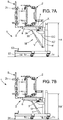
- the guide column 4 'illustrated on figure 6 is similar to that of figure 5 , with two uprights distributed on either side of a lifting jack 51. It is understood that the guide column 4 ', as clearly visible on the figure 5 and on figures 6 , 7A, and 7B , is close to the rear of the support device 3, being located on the same side (long side) of the lifting zone Z as the stop surface 7 in the loading configuration.
- the support device 3 comprises a receiver assembly 10 which may be the same or similar to that illustrated in figure 1 .
- Column 4 ' makes it possible to lift a sliding portion EC which has for example two opposite sides G connected to the lifting mechanism.
- a motorization element 30 ' placed here at the top or near the upper end of the guide column 4'.
- the sliding portion EC slides vertically between an extreme low position and an extreme high position.
- the extreme low position may correspond to pressing on an axial stop, so that the sliding portion EC is located further from the ground as the lifting part 6 (in the loading configuration).
- the lifting cylinder 51 makes it possible to move the sliding portion EC which moves along two parallel uprights of the column 4 '.
- the EC sliding portion defines an attachment zone for at least one connecting member 40 '.
- This connecting member 40 ′ which extends horizontally, delimiting a half-perimeter of the lifting zone, has two arms, optionally connected to the same base.
- the receiver assembly 10 is placed between these two arms (only one of the arms visible on the figure 5 ) and these arms can define respective bearings for a pair of rotary shafts formed on the receiver assembly 10.
- the axis of rotation X is thus defined horizontally by these shafts of an articulated connection, with a substantially constant spacing of this X axis with respect to the guide column 4 '.
- each arm of the connecting member 40 ' has a sufficient length so that the axis of rotation X is maintained at a distance (for example between 50 and 120cm) from the guide column 4' which allows a clearance for the 'Receiver assembly 10.
- a distance for example between 50 and 120cm
- the term “column” does not exclude grouping at least two uprights spaced a short distance apart (much less than the length of the receiver assembly 10) and which form a holding and guiding support for a single sliding portion EC sufficiently wide. More generally, it will be understood that the structure of the guide column 4 ′ can take different forms.
- a jack V which preferably extends parallel to one of the arms, is connected by a pivot link 36 to a frame 8 or another element (distinct from the lifting part 6) of the receiver assembly 10.
- the pivot link 36 can be positioned lower than the axis of rotation X when the rod 35 of the cylinder V is in an initial retracted position. In this initial retracted position (position not shown), the rod 35 of the cylinder V maintains the receiver assembly 10 in a starting orientation of the type shown on the drawings. figures 1 and 3 .
- the lifting part 6 is then substantially horizontal.
- the V cylinder can be electric or hydraulic.
- the jack V has an inclination. This can make it possible to bring the X axis closer to the column 4 'and thus reduce the overall size of the handling system 1.
- the man-machine interface makes it possible to modify the position of this rod 35.
- the rod 35 of the cylinder V pushes a lower part of the receiver assembly 10, which has the effect of rotating the cylinder. receiving assembly around the axis of rotation X.
- the lifting part 6 is then moved by an angle which may be greater than 45 or 70 °, the maximum rotation possibly corresponding to approximately 85 ° or 90 °.
- This is advantageously permitted by using a single jack V, here directly placed between the corresponding sliding portion EC and the receiver assembly 10.
- the way of driving the receiver assembly 10 in rotation can be adapted as needed and it is understood that this type of connection with a jack is applicable to the case illustrated on the figure 1 .
- a geared motor or the like can be used in an embodiment similar to that of the figure 5 .
- the support device 3 can carry second drive means M 'to rotate the receiver assembly 10 about the axis of rotation X.
- a sleeping unit 2 When a sleeping unit 2 is engaged with the The receiving assembly 10 coming against the stop surface 7, it is then allowed to orient the determined longitudinal side 2a (on the side of the stop surface 7) downwards in a maintenance configuration.
- the lifting can be controlled independently of the rotational movement.
- a jack (not shown) can also be used. This avoids handling and prevents a technician from intervening from the rear (access which may be less easy due to the presence of the guide column 4 ').
- the retaining element 18 may have a clamping member driven by a rhombus articulated at these vertices.
- the spacing between the pivoting connections 41 located between the lower segments and the upper segments 42 of this rhombus can be adjusted by a jack placed diagonally (horizontally) in this rhombus.
- any other adjustment member can be used, for example of the sliding rod type.
- One of the strengths of the handling system 1 with a receiving assembly 10 in one piece is that it facilitates the maintenance of heavy sleeping units 2, in particular medical beds. Thus, the technician no longer needs to move by himself (by calling on other workers) such a sleeping unit for changing wheels, jacks, motors allowing the mattress to be lifted from the bed or all the mechanical or electrical parts contributing to the operation of the bed.
- the handling system 1 is particularly robust and makes it possible to lift and turn a bed which weighs several hundred kilograms.
- the rotated positioning avoids having to perform maintenance by standing under the bed (which makes the procedure more painful, knowing that you have to lift your arms and head to repair the defective parts of the bed).
- the figures 7A and 7B successively illustrate two height levels of the sleeping unit 2, obtained for the maintenance configuration.
- the height level is obtained by the direct tilting, from the loading configuration to the maintenance configuration, of the support device 3.
- the height H4 of the lower rollers 2c can then be still high, for example greater than 150 cm from the level of the support (ground) on which the handling system 1 rests.
- the height H4 ′ is thus obtained for these same lowest rollers 2c, which is less than the height H4 and may be between 80 and 110 cm for example. .
- the underside of the sleeping unit 2 can then be perfectly in front of the operator, the height H4 'being low enough so that the other higher wheels are also accessible (for example at much less than 2 meters from the ground knowing that the width of the sleeping unit 2, close to the distance between the low casters and the high casters, typically does not exceed 90 cm).
- the flexibility of the handling system 1 is such that the receiver assembly 10 can be sized according to the needs and the space available to install the system 1. The latter can be fixed and installed in a workshop of a hospital.
- the different parts of the handling system 1 are typically removable. Provision can for example be made for receiving assemblies 10 of different size and / or capacity to be assembled on the same lifting and rotating installation.
- the guide parts 4, 5 can thus be positioned on rails R to adjust the width of the lifting zone Z, as illustrated in the figure. figure 1 .
- the receiver assembly 10 has a length of between 150 (for example for children's beds) and 230 cm.
- the handling system 1 is advantageous in that it offers a mode of adjustment of the receiver assembly 10 which allows the technician to work in very favorable ergonomic conditions, by being able to adapt the working height to his size in real time ( height adjustment possible after tilting of the receiver assembly 10 as illustrated on figure 4 or the figure 5 ).
- sliding end should not be interpreted restrictively and does not necessarily mean that the support device 3 ends laterally in such a sliding portion or end.
- end is simply used to signify that a lifting zone Z associated with the device 3 is delimited between two such sliding ends of the support device 3.
- the handling system 1 may present the case. possibly a single support device 3 common to two lifting zones Z separated from each other by an intermediate column. In this case, there are two receiving assemblies 10 formed by the same support device 3 and it can still be considered that the part which slides along the intermediate column corresponds and is functionally identical to a sliding end.
Landscapes
- Health & Medical Sciences (AREA)
- Life Sciences & Earth Sciences (AREA)
- Veterinary Medicine (AREA)
- Animal Behavior & Ethology (AREA)
- General Health & Medical Sciences (AREA)
- Public Health (AREA)
- Nursing (AREA)
- Engineering & Computer Science (AREA)
- Geology (AREA)
- Mechanical Engineering (AREA)
- Structural Engineering (AREA)
- Invalid Beds And Related Equipment (AREA)
- Accommodation For Nursing Or Treatment Tables (AREA)
Claims (14)
- Handhabungssystem (1) für rollende Schlafeinheiten (2), insbesondere Betten oder Tragen, wobei das System umfasst:- eine Stützvorrichtung (3), die durch Anheben beweglich ist, um eine Schlafeinheit (2) anzuheben, wobei die Stützvorrichtung zwei Gleitabschnitte oder Gleitenden (EC1, EC2) umfasst,- zwei Führungsteile (4, 5), die durch eine Hubzone (Z) voneinander getrennt sind und eine Bewegung der beiden Gleitenden der Stützvorrichtung vertikal führen, und- erste Antriebsmittel (30), um mindestens einen Gleitabschnitt oder ein Gleitende (EC1) der Stützvorrichtung linear zu bewegen und das Anheben der Stützvorrichtung (3) zu ermöglichen;dadurch gekennzeichnet, dass die Rückhaltemittel (8, 9) und das Hubteil (6) eine Aufnahmeanordnung (10) definieren, die abgewinkelt ist und eine zusammenhängende Einheit darstellt, wobei die Rückhaltemittel (8, 9) eine Anschlagfläche (7) bilden, die dazu bestimmt ist, mit einer bestimmten longitudinalen Seite oder Kante (2a) der Schlafeinheit (2) in Eingriff gebracht zu werden, wobei sich das Hubteil (6) in einem zentralen Unterbereich der Hubzone (Z) erstreckt, um die Rollen (2c) einer Schlafeinheit (2) auf beiden Seiten des Hubteils (6) zu verteilen,
wobei die Stützvorrichtung (3) umfasst:- ein Hubteil (6), das sich in einer Ladekonfiguration für eine Schlafeinheit (2) quer zu den beiden Führungsteilen (4, 5) erstreckt, wobei sich das Hubteil in der Ladekonfiguration in einem Abstand von den zwei Führungsteilen (4, 5) erstreckt,- Rückhaltemittel (8, 9), die mit dem Hubteil (6) fest verbunden sind, und- mindestens ein Halteelement (18), dessen Position einstellbar ist, um sich dem Hubteil (6) zu nähern oder von diesem zu entfernen;
und dass die als zusammenhängende Einheit ausgebildete Aufnahmeanordnung (10) zwischen den beiden Gleitenden (EC1, EC2) um eine im Wesentlichen horizontale Drehachse (X) schwenkbar montiert ist, wodurch das System (1) eine Haltekonfiguration für eine Schlafeinheit (2) aufweist, in der die Schlafeinheit von der Stützvorrichtung (3) angehoben und mit einer in Bezug auf die Ladekonfiguration modifizierten Orientierung gehalten wird. - Handhabungssystem nach Anspruch 1, umfassend zweite Antriebsmittel (M, 40) , um die Aufnahmeanordnung (10) um die Drehachse (X), die durch die zwei Gleitenden (EC1, C2) verläuft, nach einem Anheben der mit der Schlafeinheit (2) beladenen Stützvorrichtung (3) zu drehen, um die bestimmte longitudinale Seite (2a) in der Haltekonfiguration der Schlafeinheit nach unten zu orientieren.
- Handhabungssystem nach Anspruch 2, wobei die zweiten Antriebsmittel (M, 40) dazu konfiguriert sind, die Aufnahmeanordnung (10) um maximal eine viertel Umdrehung zu drehen, wobei der Drehwinkel über eine Mensch-Maschine-Schnittstelle einstellbar ist.
- Handhabungssystem nach Anspruch 2 oder 3, wobei die Aufnahmeanordnung (10) durch zwei Verbindungswellen mit dem einen bzw. dem anderen der beiden Gleitenden (EC1, EC2) der Stützvorrichtung (3) schwenkbar gemacht wird, wobei die zweiten Antriebsmittel (M, 40) ein einzelnes Rotationsantriebselement umfassen, um unter den zwei Verbindungswellen eine erste Antriebswelle zu definieren, wobei die zweite Welle (40) der beiden Verbindungswellen eine nachlaufende Welle ist.
- Handhabungssystem nach einem der vorhergehenden Ansprüche, wobei das Hubteil (6) durch eine Gabel gebildet ist.
- Handhabungssystem nach Anspruch 5, wobei das Hubteil (6), das einseitig mit den Rückhaltemitteln (8, 9) verbunden ist, zwei voneinander beabstandete, starre Elemente (6a, 6b) umfasst, deren Abstand eingestellt werden kann, und die jeweils oben mit einer Kontaktfläche (12) aus einem flexiblen oder/und verformbaren Material versehen sind.
- Handhabungssystem nach Anspruch 5 oder 6, wobei das Hubteil (6) eine Gabel umfasst, die mit mindestens zwei Zähnen versehen ist, die sich jeweils in Bezug zu der Anschlagfläche (7) von einem proximalen Ende (60) zu einem distalen Ende (6c) ausstrecken, und die sich vorzugsweise in einer Richtung senkrecht zur Drehachse (X) erstrecken.
- Handhabungssystem nach einem der vorhergehenden Ansprüche, umfassend eine im Wesentlichen flache Basis, die zwischen den beiden Führungsteilen (4, 5) ausgebildet ist, wobei sich das Hubteil (6) bis zu einer Höhe (H6) erstreckt, die kleiner oder gleich 25 cm und vorzugsweise kleiner als 20 cm ist, in Bezug zu der flachen Basis, in einem abgesenkten Zustand der Stützvorrichtung (3), was der Ladekonfiguration entspricht.
- Handhabungssystem nach einem der vorhergehenden Ansprüche, wobei die als zusammenhängende Einheit ausgebildete Aufnahmeanordnung (10) mit zwei Flanken ausgestattet ist, die jeweils drehbar mit den Gleitenden (EC1, EC2) verbunden sind.
- Handhabungssystem nach einem der vorhergehenden Ansprüche, wobei das Hubteil (6) im Wesentlichen flach ist und das Halteelement (18) ein Klemmelement umfasst, das in der Ladekonfiguration von oben mit den Rückhaltemitteln (8, 9) verbunden ist, wobei das Klemmelement in einer Richtung senkrecht zum Hubteil (6) beweglich ist und in einem Abstand vom Hubteil gehalten wird, was es einem Außenrahmen der Schlafeinheit (2) ermöglicht von einer den Rückhaltemitteln (8, 9) gegenüberliegenden Seite her in einen Einspannbereich eingesetzt zu werden, der zwischen dem Hubteil (6) und dem Klemmelement begrenzt ist.
- Handhabungssystem nach einem der vorhergehenden Ansprüche, ferner umfassend:- mindestens einen Sensor (16) zum Erfassen einer Eingriffsposition einer Schlafeinheit (2) an der Anschlagfläche (7), der angepasst ist, um entsprechende Erfassungsinformationen zu liefern; und- eine Steuer-/Regeleinheit (15), die konfiguriert ist, um ein Anheben der Stützvorrichtung (3) gemäß den von dem Sensor (16) gelieferten Erfassungsinformationen zu starten.
- Handhabungssystem (1) für rollende Schlafeinheiten (2), insbesondere Betten oder Tragen, wobei das System umfasst:- eine Führungssäule (4') neben einer Hubzone (Z), die entlang einer bestimmten Seite der Hubzone angeordnet ist;- eine Stützvorrichtung (3), die durch Anheben beweglich ist, um eine Schlafeinheit (2) anzuheben, wobei die Stützvorrichtung einen Gleitabschnitt (EC) umfasst, der an der Führungssäule (4') befestigt und entlang der Führungssäule vertikal geführt ist, und- erste Antriebsmittel (30'), um den Gleitabschnitt (EC) der Stützvorrichtung linear zu bewegen und das Anheben der Stützvorrichtung (3) zu ermöglichen;wobei die Aufnahmeanordnung (10) um eine im Wesentlichen horizontale Drehachse (X) schwenkbar montiert ist, die durch eine Gelenkverbindung zwischen dem Gleitabschnitt (EC) und der Aufnahmeanordnung (10) definiert ist, wodurch das System (1) eine Haltekonfiguration für eine Schlafeinheit (2) aufweist, in der die Schlafeinheit von der Stützvorrichtung (3) angehoben und in einer in Bezug auf die Ladekonfiguration modifizierten Orientierung gehalten wird.
dadurch gekennzeichnet, dass die Stützvorrichtung (3) umfasst:- ein vorzugsweise durch eine Gabel gebildetes Hubteil (6), das sich in einer Ladekonfiguration für eine Schlafeinheit (2) quer zur Führungssäule (4') erstreckt;- Rückhaltemittel (8), die fest mit dem Hubteil (6) verbunden sind und eine Anschlagfläche (7) bilden, die dazu bestimmt ist, mit einer bestimmten longitudinalen Seite oder Kante (2a) der Schlafeinheit (2) in Eingriff gebracht zu werden; wobei die Rückhaltemittel und das Hubteil eine Aufnahmeanordnung (10) definieren, wobei sich die Rückhaltemittel (8) in der Ladekonfiguration auf der bestimmten Seite der Hubzone (Z) erstrecken, und- mindestens ein Halteelement (18), dessen Position einstellbar ist, um sich dem Hubteil (6) anzunähern oder von diesem zu entfernen, - Handhabungssystem nach Anspruch 12, umfassend zweite Antriebsmittel (M'), um die Aufnahmeanordnung (10) um die Drehachse (X) zu drehen, um die bestimmte longitudinale Seite (2a) in der Haltekonfiguration für die Schlafeinheit (2) nach unten zu orientieren, wobei die Drehachse (X) unabhängig vom Höhenniveau der Stützvorrichtung (3) in einem konstanten Abstand von der Führungssäule (4') gehalten wird.
- Verfahren zum Positionieren einer rollenden Schlafeinheit (2), insbesondere eines Bettes oder einer Trage, für einen Wartungs-/Reparaturvorgang, umfassend die Schritte, die im Wesentlichen bestehen aus:- Positionieren einer Schlafeinheit (2) in einer Hubzone (Z) über einem Hubteil (6), das Teil einer Stützvorrichtung (3) ist, wobei sich die Hubzone entlang einer Führungssäule (4') oder zwischen zwei Führungsteilen (4, 5) befindet;- In-Eingriff-Bringen einer bestimmten longitudinalen Seite (2a) der Schlafeinheit (2) mit einer Anschlagfläche (7), die fest mit dem Hubteil (6) verbunden ist und sich quer zum Hubteil erstreckt, so dass die Schlafeinheit (2) in einer Aufnahmeanordnung (10) in einer Ladekonfiguration aufgenommen wird;- Einstellen der Position von mindestens einem Halteelement (18) der Schlafeinheit (2), von oben, um eine verriegelte relative Position zwischen der Schlafeinheit (2) und der Aufnahmeanordnung (10) zu erhalten;- Anheben der Schlafeinheit (2) durch eine lineare Bewegung der Stützvorrichtung (3), mit Führung entlang der Führungssäule (4') oder der beiden Führungsteile (4, 5); und- jenseits eines vorbestimmten Grenzwerts für die Höhe, Drehen der Aufnahmeanordnung (10) und der Schlafeinheit (2), die in der verriegelten Position gehalten werden, um eine im Wesentlichen horizontale Drehachse (X), wobei die Anschlagfläche (7) nach unten bewegt wird, bis eine Haltekonfiguration für die Schlafeinheit (2) erhalten wird, in der die Schlafeinheit von der Stützvorrichtung (3) angehoben und gehalten wird, wobei sie eine gegenüber der Ladekonfiguration modifizierte Orientierung aufweist.
Applications Claiming Priority (2)
| Application Number | Priority Date | Filing Date | Title |
|---|---|---|---|
| FR1560160A FR3042786B1 (fr) | 2015-10-23 | 2015-10-23 | Systeme et methode de manutention pour faciliter la maintenance d'une unite de couchage, en particulier un lit medicalise |
| PCT/FR2016/052697 WO2017068280A1 (fr) | 2015-10-23 | 2016-10-19 | Système et méthode de manutention pour faciliter la maintenance d'une unité de couchage, en particulier un lit médicalisé |
Publications (2)
| Publication Number | Publication Date |
|---|---|
| EP3364930A1 EP3364930A1 (de) | 2018-08-29 |
| EP3364930B1 true EP3364930B1 (de) | 2020-09-23 |
Family
ID=54783896
Family Applications (1)
| Application Number | Title | Priority Date | Filing Date |
|---|---|---|---|
| EP16809459.7A Active EP3364930B1 (de) | 2015-10-23 | 2016-10-19 | Handhabungssystem und verfahren zur erleichterung der wartung einer schlafeinheit, insbesondere eines pflegebettes |
Country Status (6)
| Country | Link |
|---|---|
| US (1) | US10828215B2 (de) |
| EP (1) | EP3364930B1 (de) |
| CA (1) | CA3002784C (de) |
| ES (1) | ES2826409T3 (de) |
| FR (1) | FR3042786B1 (de) |
| WO (1) | WO2017068280A1 (de) |
Families Citing this family (9)
| Publication number | Priority date | Publication date | Assignee | Title |
|---|---|---|---|---|
| FR3042786B1 (fr) * | 2015-10-23 | 2021-01-29 | Univ De Caen | Systeme et methode de manutention pour faciliter la maintenance d'une unite de couchage, en particulier un lit medicalise |
| DE102016115982B4 (de) * | 2016-08-26 | 2019-01-17 | ReActive Robotics GmbH | Vorrichtung zur Überführung eines Bettes aus einer bezüglich seiner Längsseiten horizontalen in eine geneigte Position |
| DE102018129370A1 (de) * | 2018-11-21 | 2020-05-28 | ReActive Robotics GmbH | Vorrichtung und Verfahren zur reversiblen Verbindung eines Rehabilitationsmechanismus mit einem Bett, sowie Verfahren zum Betreiben eines mit einem Bett verbundenen Rehabilitationsmechanismus |
| CN110884823B (zh) * | 2019-11-07 | 2025-01-14 | 机械工业第四设计研究院有限公司 | 一种电动端挡机构 |
| CN113548603A (zh) * | 2020-04-24 | 2021-10-26 | 上海微电子装备(集团)股份有限公司 | 一种光栅组件集成装置及方法 |
| WO2023114490A2 (en) * | 2021-12-17 | 2023-06-22 | Fast-Sexing Technologies Ulc | Devices, methods and systems for restraining, transporting and manipulating animals |
| CN114886265B (zh) * | 2022-06-30 | 2023-11-03 | 慕思健康睡眠股份有限公司 | 一种床单夹持装置及床架 |
| CN115317643B (zh) * | 2022-08-09 | 2023-08-04 | 中国人民解放军总医院第四医学中心 | 一种病床底部消毒装置 |
| CN118125292B (zh) * | 2024-05-10 | 2024-07-09 | 山西三建集团有限公司 | 一种装配式钢结构建筑用吊装装置 |
Family Cites Families (10)
| Publication number | Priority date | Publication date | Assignee | Title |
|---|---|---|---|---|
| GB786302A (en) | 1955-07-06 | 1957-11-13 | Lewis Frederick Alexander | Improvements in or relating to bed-lifting jacks |
| US3876024A (en) * | 1972-12-07 | 1975-04-08 | Said Charles S Mitchell To Sai | Motorized vehicle for moving hospital beds and the like |
| US4239196A (en) * | 1979-05-09 | 1980-12-16 | Hanger James E | Engine stand |
| SE428091B (sv) * | 1979-07-16 | 1983-06-06 | Hans Arne Valentin Johansson | Anordning for att hantera ett objekt som skall rengoras |
| US7448606B1 (en) * | 2003-12-04 | 2008-11-11 | Innovative Tools & Technologies, Inc. | Large automotive panel paint rack |
| GB2428661A (en) | 2005-07-27 | 2007-02-07 | Huntleigh Technology Plc | Bed lifting and tilting frames |
| US8596627B2 (en) * | 2009-11-02 | 2013-12-03 | Wurk Metal Products, Inc. | Automobile rotisserie |
| FR2956653B1 (fr) * | 2010-02-19 | 2012-02-10 | Solhymeca Solution Hygiene Mecanique | Dispositif de manutention d'objets pour au moins retourner un meuble, tel que par exemple un lit. |
| US9038218B1 (en) * | 2014-01-15 | 2015-05-26 | Hill-Rom Services, Inc. | Person support apparatuses with selectively coupled foot sections |
| FR3042786B1 (fr) * | 2015-10-23 | 2021-01-29 | Univ De Caen | Systeme et methode de manutention pour faciliter la maintenance d'une unite de couchage, en particulier un lit medicalise |
-
2015
- 2015-10-23 FR FR1560160A patent/FR3042786B1/fr active Active
-
2016
- 2016-10-19 CA CA3002784A patent/CA3002784C/fr active Active
- 2016-10-19 US US15/770,406 patent/US10828215B2/en active Active
- 2016-10-19 WO PCT/FR2016/052697 patent/WO2017068280A1/fr not_active Ceased
- 2016-10-19 ES ES16809459T patent/ES2826409T3/es active Active
- 2016-10-19 EP EP16809459.7A patent/EP3364930B1/de active Active
Non-Patent Citations (1)
| Title |
|---|
| None * |
Also Published As
| Publication number | Publication date |
|---|---|
| WO2017068280A1 (fr) | 2017-04-27 |
| EP3364930A1 (de) | 2018-08-29 |
| FR3042786A1 (fr) | 2017-04-28 |
| US10828215B2 (en) | 2020-11-10 |
| CA3002784C (fr) | 2023-08-22 |
| US20180311096A1 (en) | 2018-11-01 |
| FR3042786B1 (fr) | 2021-01-29 |
| CA3002784A1 (fr) | 2017-04-27 |
| ES2826409T3 (es) | 2021-05-18 |
Similar Documents
| Publication | Publication Date | Title |
|---|---|---|
| CA3002784C (fr) | Systeme et methode de manutention pour faciliter la maintenance d'une unite de couchage, en particulier un lit medicalise | |
| FR2587784A1 (fr) | Structure extensible et retractable a plan orientable | |
| FR3064619A1 (fr) | Procede et dispositif de soutien d'une roue | |
| FR2518515A1 (fr) | Dispositif d'alimentation a centrage automatique pour objets allonges | |
| FR3071209A1 (fr) | Systeme de manutention d’element de construction longitudinal, vehicule de manutation equipe d’un tel systeme | |
| FR3068026A1 (fr) | Dispositif pour la manutention d'objet | |
| FR2956653A1 (fr) | Dispositif de manutention d'objets pour au moins retourner un meuble, tes que par exemple un lit. | |
| EP3215692B1 (de) | Rollwagen für einen teleskopmast einer plattenhebevorrichtung, mit diesem wagen ausgestattete vorrichtung und implementierungsverfahren | |
| EP1418151B1 (de) | Gestell mit Gelenkvorrichtungen für Stützarme | |
| WO2010103214A1 (fr) | Banderoleuse mobile a bras tournant | |
| FR2689073A1 (fr) | Appareillage de manutention de charges allongées sur le toit d'un véhicule. | |
| EP3320802B1 (de) | Spieltisch, der mit rollen und einziehbaren beinen ausgestattet ist | |
| EP3217842A1 (de) | Möbelstück mit einem körper mit stützbeinen | |
| EP0330556B1 (de) | Drehscheibe zum Ausstellen eines Kraftfahrzeuges | |
| EP0185826B1 (de) | Hebevorrichtung für Lader an Landwirtschaftstraktoren | |
| FR3125807A1 (fr) | Dispositif de déplacement-basculement d’une pile d’objets | |
| FR2607535A1 (fr) | Echafaudage a plate-forme mobile | |
| FR2872475A1 (fr) | Plateau porte charge roulant elevateur | |
| FR2625883A1 (fr) | Dispositif pour le reglage en inclinaison et/ou en hauteur d'un plan de travail ou de table d'un meuble | |
| FR3149317A1 (fr) | Dispositif de levage suspendu d’éléments allongés permettant differentes inclinaisons | |
| FR3079119A1 (fr) | Dispositif d’aide au passage de la position assise a la position debout, et inversement, plateforme de mobilite pour siege comprenant un tel dispositif, et siege roulant | |
| FR2877656A1 (fr) | Systeme de plate-forme elevatrice | |
| WO2022167989A1 (fr) | Dispositif motorisé destiné à se fixer à une roue de véhicule pour le déplacer | |
| FR3077064A1 (fr) | Engin de levage a fleche articulee | |
| FR3007010A1 (fr) | Plateforme elevatrice de personnel integrant une liaison avec un double embiellage optimisee |
Legal Events
| Date | Code | Title | Description |
|---|---|---|---|
| STAA | Information on the status of an ep patent application or granted ep patent |
Free format text: STATUS: UNKNOWN |
|
| STAA | Information on the status of an ep patent application or granted ep patent |
Free format text: STATUS: THE INTERNATIONAL PUBLICATION HAS BEEN MADE |
|
| PUAI | Public reference made under article 153(3) epc to a published international application that has entered the european phase |
Free format text: ORIGINAL CODE: 0009012 |
|
| STAA | Information on the status of an ep patent application or granted ep patent |
Free format text: STATUS: REQUEST FOR EXAMINATION WAS MADE |
|
| 17P | Request for examination filed |
Effective date: 20180423 |
|
| AK | Designated contracting states |
Kind code of ref document: A1 Designated state(s): AL AT BE BG CH CY CZ DE DK EE ES FI FR GB GR HR HU IE IS IT LI LT LU LV MC MK MT NL NO PL PT RO RS SE SI SK SM TR |
|
| AX | Request for extension of the european patent |
Extension state: BA ME |
|
| DAV | Request for validation of the european patent (deleted) | ||
| DAX | Request for extension of the european patent (deleted) | ||
| GRAP | Despatch of communication of intention to grant a patent |
Free format text: ORIGINAL CODE: EPIDOSNIGR1 |
|
| STAA | Information on the status of an ep patent application or granted ep patent |
Free format text: STATUS: GRANT OF PATENT IS INTENDED |
|
| INTG | Intention to grant announced |
Effective date: 20200428 |
|
| GRAS | Grant fee paid |
Free format text: ORIGINAL CODE: EPIDOSNIGR3 |
|
| GRAA | (expected) grant |
Free format text: ORIGINAL CODE: 0009210 |
|
| STAA | Information on the status of an ep patent application or granted ep patent |
Free format text: STATUS: THE PATENT HAS BEEN GRANTED |
|
| AK | Designated contracting states |
Kind code of ref document: B1 Designated state(s): AL AT BE BG CH CY CZ DE DK EE ES FI FR GB GR HR HU IE IS IT LI LT LU LV MC MK MT NL NO PL PT RO RS SE SI SK SM TR |
|
| REG | Reference to a national code |
Ref country code: GB Ref legal event code: FG4D Free format text: NOT ENGLISH |
|
| REG | Reference to a national code |
Ref country code: CH Ref legal event code: EP |
|
| REG | Reference to a national code |
Ref country code: IE Ref legal event code: FG4D Free format text: LANGUAGE OF EP DOCUMENT: FRENCH |
|
| REG | Reference to a national code |
Ref country code: DE Ref legal event code: R096 Ref document number: 602016044634 Country of ref document: DE Ref country code: AT Ref legal event code: REF Ref document number: 1315636 Country of ref document: AT Kind code of ref document: T Effective date: 20201015 |
|
| PG25 | Lapsed in a contracting state [announced via postgrant information from national office to epo] |
Ref country code: BG Free format text: LAPSE BECAUSE OF FAILURE TO SUBMIT A TRANSLATION OF THE DESCRIPTION OR TO PAY THE FEE WITHIN THE PRESCRIBED TIME-LIMIT Effective date: 20201223 Ref country code: HR Free format text: LAPSE BECAUSE OF FAILURE TO SUBMIT A TRANSLATION OF THE DESCRIPTION OR TO PAY THE FEE WITHIN THE PRESCRIBED TIME-LIMIT Effective date: 20200923 Ref country code: SE Free format text: LAPSE BECAUSE OF FAILURE TO SUBMIT A TRANSLATION OF THE DESCRIPTION OR TO PAY THE FEE WITHIN THE PRESCRIBED TIME-LIMIT Effective date: 20200923 Ref country code: NO Free format text: LAPSE BECAUSE OF FAILURE TO SUBMIT A TRANSLATION OF THE DESCRIPTION OR TO PAY THE FEE WITHIN THE PRESCRIBED TIME-LIMIT Effective date: 20201223 Ref country code: FI Free format text: LAPSE BECAUSE OF FAILURE TO SUBMIT A TRANSLATION OF THE DESCRIPTION OR TO PAY THE FEE WITHIN THE PRESCRIBED TIME-LIMIT Effective date: 20200923 Ref country code: GR Free format text: LAPSE BECAUSE OF FAILURE TO SUBMIT A TRANSLATION OF THE DESCRIPTION OR TO PAY THE FEE WITHIN THE PRESCRIBED TIME-LIMIT Effective date: 20201224 |
|
| PG25 | Lapsed in a contracting state [announced via postgrant information from national office to epo] |
Ref country code: RS Free format text: LAPSE BECAUSE OF FAILURE TO SUBMIT A TRANSLATION OF THE DESCRIPTION OR TO PAY THE FEE WITHIN THE PRESCRIBED TIME-LIMIT Effective date: 20200923 Ref country code: LV Free format text: LAPSE BECAUSE OF FAILURE TO SUBMIT A TRANSLATION OF THE DESCRIPTION OR TO PAY THE FEE WITHIN THE PRESCRIBED TIME-LIMIT Effective date: 20200923 |
|
| REG | Reference to a national code |
Ref country code: NL Ref legal event code: MP Effective date: 20200923 |
|
| REG | Reference to a national code |
Ref country code: LT Ref legal event code: MG4D |
|
| REG | Reference to a national code |
Ref country code: AT Ref legal event code: UEP Ref document number: 1315636 Country of ref document: AT Kind code of ref document: T Effective date: 20200923 |
|
| PG25 | Lapsed in a contracting state [announced via postgrant information from national office to epo] |
Ref country code: EE Free format text: LAPSE BECAUSE OF FAILURE TO SUBMIT A TRANSLATION OF THE DESCRIPTION OR TO PAY THE FEE WITHIN THE PRESCRIBED TIME-LIMIT Effective date: 20200923 Ref country code: SM Free format text: LAPSE BECAUSE OF FAILURE TO SUBMIT A TRANSLATION OF THE DESCRIPTION OR TO PAY THE FEE WITHIN THE PRESCRIBED TIME-LIMIT Effective date: 20200923 Ref country code: CZ Free format text: LAPSE BECAUSE OF FAILURE TO SUBMIT A TRANSLATION OF THE DESCRIPTION OR TO PAY THE FEE WITHIN THE PRESCRIBED TIME-LIMIT Effective date: 20200923 Ref country code: PT Free format text: LAPSE BECAUSE OF FAILURE TO SUBMIT A TRANSLATION OF THE DESCRIPTION OR TO PAY THE FEE WITHIN THE PRESCRIBED TIME-LIMIT Effective date: 20210125 Ref country code: RO Free format text: LAPSE BECAUSE OF FAILURE TO SUBMIT A TRANSLATION OF THE DESCRIPTION OR TO PAY THE FEE WITHIN THE PRESCRIBED TIME-LIMIT Effective date: 20200923 Ref country code: LT Free format text: LAPSE BECAUSE OF FAILURE TO SUBMIT A TRANSLATION OF THE DESCRIPTION OR TO PAY THE FEE WITHIN THE PRESCRIBED TIME-LIMIT Effective date: 20200923 |
|
| REG | Reference to a national code |
Ref country code: ES Ref legal event code: FG2A Ref document number: 2826409 Country of ref document: ES Kind code of ref document: T3 Effective date: 20210518 |
|
| PG25 | Lapsed in a contracting state [announced via postgrant information from national office to epo] |
Ref country code: PL Free format text: LAPSE BECAUSE OF FAILURE TO SUBMIT A TRANSLATION OF THE DESCRIPTION OR TO PAY THE FEE WITHIN THE PRESCRIBED TIME-LIMIT Effective date: 20200923 Ref country code: IS Free format text: LAPSE BECAUSE OF FAILURE TO SUBMIT A TRANSLATION OF THE DESCRIPTION OR TO PAY THE FEE WITHIN THE PRESCRIBED TIME-LIMIT Effective date: 20210123 Ref country code: AL Free format text: LAPSE BECAUSE OF FAILURE TO SUBMIT A TRANSLATION OF THE DESCRIPTION OR TO PAY THE FEE WITHIN THE PRESCRIBED TIME-LIMIT Effective date: 20200923 |
|
| REG | Reference to a national code |
Ref country code: CH Ref legal event code: PL |
|
| REG | Reference to a national code |
Ref country code: DE Ref legal event code: R097 Ref document number: 602016044634 Country of ref document: DE |
|
| PG25 | Lapsed in a contracting state [announced via postgrant information from national office to epo] |
Ref country code: SK Free format text: LAPSE BECAUSE OF FAILURE TO SUBMIT A TRANSLATION OF THE DESCRIPTION OR TO PAY THE FEE WITHIN THE PRESCRIBED TIME-LIMIT Effective date: 20200923 Ref country code: MC Free format text: LAPSE BECAUSE OF FAILURE TO SUBMIT A TRANSLATION OF THE DESCRIPTION OR TO PAY THE FEE WITHIN THE PRESCRIBED TIME-LIMIT Effective date: 20200923 Ref country code: LU Free format text: LAPSE BECAUSE OF NON-PAYMENT OF DUE FEES Effective date: 20201019 |
|
| PLBE | No opposition filed within time limit |
Free format text: ORIGINAL CODE: 0009261 |
|
| STAA | Information on the status of an ep patent application or granted ep patent |
Free format text: STATUS: NO OPPOSITION FILED WITHIN TIME LIMIT |
|
| PG25 | Lapsed in a contracting state [announced via postgrant information from national office to epo] |
Ref country code: LI Free format text: LAPSE BECAUSE OF NON-PAYMENT OF DUE FEES Effective date: 20201031 Ref country code: SI Free format text: LAPSE BECAUSE OF FAILURE TO SUBMIT A TRANSLATION OF THE DESCRIPTION OR TO PAY THE FEE WITHIN THE PRESCRIBED TIME-LIMIT Effective date: 20200923 Ref country code: CH Free format text: LAPSE BECAUSE OF NON-PAYMENT OF DUE FEES Effective date: 20201031 Ref country code: DK Free format text: LAPSE BECAUSE OF FAILURE TO SUBMIT A TRANSLATION OF THE DESCRIPTION OR TO PAY THE FEE WITHIN THE PRESCRIBED TIME-LIMIT Effective date: 20200923 |
|
| 26N | No opposition filed |
Effective date: 20210624 |
|
| PG25 | Lapsed in a contracting state [announced via postgrant information from national office to epo] |
Ref country code: IE Free format text: LAPSE BECAUSE OF NON-PAYMENT OF DUE FEES Effective date: 20201019 |
|
| PG25 | Lapsed in a contracting state [announced via postgrant information from national office to epo] |
Ref country code: TR Free format text: LAPSE BECAUSE OF FAILURE TO SUBMIT A TRANSLATION OF THE DESCRIPTION OR TO PAY THE FEE WITHIN THE PRESCRIBED TIME-LIMIT Effective date: 20200923 Ref country code: MT Free format text: LAPSE BECAUSE OF FAILURE TO SUBMIT A TRANSLATION OF THE DESCRIPTION OR TO PAY THE FEE WITHIN THE PRESCRIBED TIME-LIMIT Effective date: 20200923 Ref country code: CY Free format text: LAPSE BECAUSE OF FAILURE TO SUBMIT A TRANSLATION OF THE DESCRIPTION OR TO PAY THE FEE WITHIN THE PRESCRIBED TIME-LIMIT Effective date: 20200923 |
|
| PG25 | Lapsed in a contracting state [announced via postgrant information from national office to epo] |
Ref country code: MK Free format text: LAPSE BECAUSE OF FAILURE TO SUBMIT A TRANSLATION OF THE DESCRIPTION OR TO PAY THE FEE WITHIN THE PRESCRIBED TIME-LIMIT Effective date: 20200923 |
|
| PG25 | Lapsed in a contracting state [announced via postgrant information from national office to epo] |
Ref country code: NL Free format text: LAPSE BECAUSE OF NON-PAYMENT OF DUE FEES Effective date: 20200923 |
|
| PGFP | Annual fee paid to national office [announced via postgrant information from national office to epo] |
Ref country code: DE Payment date: 20251021 Year of fee payment: 10 |
|
| PGFP | Annual fee paid to national office [announced via postgrant information from national office to epo] |
Ref country code: GB Payment date: 20251022 Year of fee payment: 10 |
|
| PGFP | Annual fee paid to national office [announced via postgrant information from national office to epo] |
Ref country code: AT Payment date: 20251022 Year of fee payment: 10 |
|
| PGFP | Annual fee paid to national office [announced via postgrant information from national office to epo] |
Ref country code: IT Payment date: 20251024 Year of fee payment: 10 |
|
| PGFP | Annual fee paid to national office [announced via postgrant information from national office to epo] |
Ref country code: FR Payment date: 20251030 Year of fee payment: 10 |
|
| PGFP | Annual fee paid to national office [announced via postgrant information from national office to epo] |
Ref country code: BE Payment date: 20251021 Year of fee payment: 10 |
|
| PGFP | Annual fee paid to national office [announced via postgrant information from national office to epo] |
Ref country code: ES Payment date: 20251216 Year of fee payment: 10 |