EP3364573A1 - Procédé de communication et transmetteur radio - Google Patents
Procédé de communication et transmetteur radio Download PDFInfo
- Publication number
- EP3364573A1 EP3364573A1 EP18165377.5A EP18165377A EP3364573A1 EP 3364573 A1 EP3364573 A1 EP 3364573A1 EP 18165377 A EP18165377 A EP 18165377A EP 3364573 A1 EP3364573 A1 EP 3364573A1
- Authority
- EP
- European Patent Office
- Prior art keywords
- subcarriers
- channels
- subcarrier
- frequency
- data
- Prior art date
- Legal status (The legal status is an assumption and is not a legal conclusion. Google has not performed a legal analysis and makes no representation as to the accuracy of the status listed.)
- Granted
Links
- 238000004891 communication Methods 0.000 title claims abstract description 170
- 238000000034 method Methods 0.000 title claims description 39
- 230000005540 biological transmission Effects 0.000 claims abstract description 105
- 238000012545 processing Methods 0.000 claims description 36
- 238000013507 mapping Methods 0.000 abstract description 26
- 238000006243 chemical reaction Methods 0.000 description 56
- 230000006866 deterioration Effects 0.000 description 27
- 238000010586 diagram Methods 0.000 description 20
- 230000015556 catabolic process Effects 0.000 description 19
- 238000006731 degradation reaction Methods 0.000 description 19
- 238000012937 correction Methods 0.000 description 15
- 238000005516 engineering process Methods 0.000 description 7
- 238000003780 insertion Methods 0.000 description 7
- 230000037431 insertion Effects 0.000 description 7
- 238000001228 spectrum Methods 0.000 description 5
- 239000000969 carrier Substances 0.000 description 2
- 238000007796 conventional method Methods 0.000 description 2
- 238000005070 sampling Methods 0.000 description 2
- 229930091051 Arenine Natural products 0.000 description 1
- 230000003247 decreasing effect Effects 0.000 description 1
- 238000005562 fading Methods 0.000 description 1
- 238000001914 filtration Methods 0.000 description 1
- 230000010363 phase shift Effects 0.000 description 1
- 230000008685 targeting Effects 0.000 description 1
Images


Classifications
-
- H—ELECTRICITY
- H04—ELECTRIC COMMUNICATION TECHNIQUE
- H04L—TRANSMISSION OF DIGITAL INFORMATION, e.g. TELEGRAPHIC COMMUNICATION
- H04L27/00—Modulated-carrier systems
- H04L27/26—Systems using multi-frequency codes
- H04L27/2601—Multicarrier modulation systems
- H04L27/2647—Arrangements specific to the receiver only
- H04L27/2649—Demodulators
- H04L27/26524—Fast Fourier transform [FFT] or discrete Fourier transform [DFT] demodulators in combination with other circuits for demodulation
-
- H—ELECTRICITY
- H04—ELECTRIC COMMUNICATION TECHNIQUE
- H04L—TRANSMISSION OF DIGITAL INFORMATION, e.g. TELEGRAPHIC COMMUNICATION
- H04L27/00—Modulated-carrier systems
- H04L27/26—Systems using multi-frequency codes
- H04L27/2601—Multicarrier modulation systems
- H04L27/2626—Arrangements specific to the transmitter only
- H04L27/2627—Modulators
-
- H—ELECTRICITY
- H04—ELECTRIC COMMUNICATION TECHNIQUE
- H04L—TRANSMISSION OF DIGITAL INFORMATION, e.g. TELEGRAPHIC COMMUNICATION
- H04L27/00—Modulated-carrier systems
- H04L27/26—Systems using multi-frequency codes
- H04L27/2601—Multicarrier modulation systems
- H04L27/2647—Arrangements specific to the receiver only
-
- H—ELECTRICITY
- H04—ELECTRIC COMMUNICATION TECHNIQUE
- H04L—TRANSMISSION OF DIGITAL INFORMATION, e.g. TELEGRAPHIC COMMUNICATION
- H04L5/00—Arrangements affording multiple use of the transmission path
- H04L5/0001—Arrangements for dividing the transmission path
- H04L5/0003—Two-dimensional division
- H04L5/0005—Time-frequency
- H04L5/0007—Time-frequency the frequencies being orthogonal, e.g. OFDM(A), DMT
- H04L5/001—Time-frequency the frequencies being orthogonal, e.g. OFDM(A), DMT the frequencies being arranged in component carriers
-
- H—ELECTRICITY
- H04—ELECTRIC COMMUNICATION TECHNIQUE
- H04L—TRANSMISSION OF DIGITAL INFORMATION, e.g. TELEGRAPHIC COMMUNICATION
- H04L5/00—Arrangements affording multiple use of the transmission path
- H04L5/003—Arrangements for allocating sub-channels of the transmission path
- H04L5/0037—Inter-user or inter-terminal allocation
- H04L5/0039—Frequency-contiguous, i.e. with no allocation of frequencies for one user or terminal between the frequencies allocated to another
-
- H—ELECTRICITY
- H04—ELECTRIC COMMUNICATION TECHNIQUE
- H04L—TRANSMISSION OF DIGITAL INFORMATION, e.g. TELEGRAPHIC COMMUNICATION
- H04L5/00—Arrangements affording multiple use of the transmission path
- H04L5/003—Arrangements for allocating sub-channels of the transmission path
- H04L5/0044—Arrangements for allocating sub-channels of the transmission path allocation of payload
-
- H—ELECTRICITY
- H04—ELECTRIC COMMUNICATION TECHNIQUE
- H04L—TRANSMISSION OF DIGITAL INFORMATION, e.g. TELEGRAPHIC COMMUNICATION
- H04L5/00—Arrangements affording multiple use of the transmission path
- H04L5/003—Arrangements for allocating sub-channels of the transmission path
- H04L5/0053—Allocation of signaling, i.e. of overhead other than pilot signals
-
- H—ELECTRICITY
- H04—ELECTRIC COMMUNICATION TECHNIQUE
- H04L—TRANSMISSION OF DIGITAL INFORMATION, e.g. TELEGRAPHIC COMMUNICATION
- H04L5/00—Arrangements affording multiple use of the transmission path
- H04L5/02—Channels characterised by the type of signal
- H04L5/023—Multiplexing of multicarrier modulation signals
-
- H—ELECTRICITY
- H04—ELECTRIC COMMUNICATION TECHNIQUE
- H04W—WIRELESS COMMUNICATION NETWORKS
- H04W72/00—Local resource management
- H04W72/04—Wireless resource allocation
-
- H—ELECTRICITY
- H04—ELECTRIC COMMUNICATION TECHNIQUE
- H04W—WIRELESS COMMUNICATION NETWORKS
- H04W72/00—Local resource management
- H04W72/04—Wireless resource allocation
- H04W72/044—Wireless resource allocation based on the type of the allocated resource
- H04W72/0453—Resources in frequency domain, e.g. a carrier in FDMA
-
- H—ELECTRICITY
- H04—ELECTRIC COMMUNICATION TECHNIQUE
- H04W—WIRELESS COMMUNICATION NETWORKS
- H04W72/00—Local resource management
- H04W72/04—Wireless resource allocation
- H04W72/044—Wireless resource allocation based on the type of the allocated resource
- H04W72/0473—Wireless resource allocation based on the type of the allocated resource the resource being transmission power
-
- H—ELECTRICITY
- H04—ELECTRIC COMMUNICATION TECHNIQUE
- H04W—WIRELESS COMMUNICATION NETWORKS
- H04W72/00—Local resource management
- H04W72/20—Control channels or signalling for resource management
-
- H—ELECTRICITY
- H04—ELECTRIC COMMUNICATION TECHNIQUE
- H04W—WIRELESS COMMUNICATION NETWORKS
- H04W84/00—Network topologies
- H04W84/02—Hierarchically pre-organised networks, e.g. paging networks, cellular networks, WLAN [Wireless Local Area Network] or WLL [Wireless Local Loop]
- H04W84/10—Small scale networks; Flat hierarchical networks
- H04W84/12—WLAN [Wireless Local Area Networks]
Definitions
- the present invention relates to a communication method and a radio transmitter that perform radio transmission with a multi-carrier transmission system using communication slots.
- a requirement needed for realizing high speed transmission rate radio communication is to increase frequency utilization efficiency. Since the transmission rate and a bandwidth used are in a direct proportional relationship, a simple solution to increase the transmission rate is to broaden the frequency bandwidth to be used. However, frequency bands that can be used are becoming scarcer and it is therefore unlikely that sufficient bandwidth be assigned for constructing a new radio communication system. Consequently, it becomes necessary to increase frequency utilization efficiency.
- another requirement is to seamlessly provide services in a private area (isolated cell) such as a wireless LAN while realizing services in a communication area composed of cells such as mobile phones.
- a technology that has a potential for meeting these requirements includes one-cell repetition OFDMA (Orthogonal Frequency Division Multiple Access).
- OFDMA Orthogonal Frequency Division Multiple Access
- communication is performed by using the same frequency band in all cells in a communication area composed of these cells, and a modulation system for performing communication is OFDM.
- This communication method can realize faster data communication while isolated cells have a radio interface common to that of a cell area as a matter of course.
- the OFDM system is used in IEEE802.11a, which is a 5GHz-band radio system, and Digital Terrestrial Broadcasting.
- the OFDM system arranges several tens to several thousands of carriers at theoretically minimum frequency intervals with no interference for simultaneous communications.
- these carriers are usually called subcarriers and each subcarrier is modulated by a digital system such as PSK (phase shift modulation) and QAM (quadrature amplitude modulation) for communication.
- the OFDM is said to be a frequency-selective fading resistant modulation system in combination with an error correction system.
- Fig. 6 is a block diagram illustrating a schematic configuration of a modulation circuit of the OFDM.
- the modulation circuit shown in Fig. 6 includes an error correction coding part 501, a serial to parallel conversion part (S/P conversion part) 502, a mapping part 503, an IFFT part 504, a parallel to serial part (P/S conversion part) 505, a guard interval insertion part 506, a digital to analog conversion part (D/A conversion part) 507, a radio transmission part 508, and an antenna 509.
- Error correction encoding of information data to be transmitted is performed by the error correction coding part 501.
- a modulation scheme of each carrier is QPSK (four-phase modulation)
- 2 X 768 1536 bits are output from an error correction coding circuit to generate one OFDM symbol.
- 2 bits are input into the mapping part 503 at a time from the S/P conversion part 502 as 768-system data, and modulation is performed by the mapping part 503 for each carrier.
- the IFFT part 504 performs IFFT (Inverse Fast Fourier Transform).
- the number of points of the IFFT usually used for generating a 768-subcarrier OFDM signal is 1024.
- Data is allocated to f(n) (n is an integer between 0 and 1023) by the mapping part and thus the IFET part 504 will output data t(n). Since only 768 pieces of data are input for 1024-point IFFT input in the present example, zero (both real and imaginary parts) is input as other pieces of data. Normally, f(0) and f (385) to f(639) correspond to input of zero. Then, after the data is converted to serial data by the P/S conversion part 505, guard intervals are inserted by the guard interval insertion part 506. Guard intervals are inserted for reducing interference between symbols when receiving an OFDM signal.
- IFFT output t(n) is output in order of t(0), t(1),...., t(1023) and these form symbols of the OFDM.
- guard intervals a latter half part of IFFT output will be output in accordance with a guard interval length. If the guard interval length is 1/8 of a normal OFDM symbol, t(n) will be output in order of t(896), t(897),...., t(1023), t(0), t(1),....t(1023). Then, after the data is converted to an analog signal by the D/A conversion part 507, the analog signal is converted to a frequency to be used for transmission, and then the data is transmitted from the antenna 509.
- Fig. 7 illustrates a schematic view of spectrum of an OFDM signal after D/A conversion, a schematic view of time waveforms after D/A conversion, and a schematic view after frequency conversion of the spectrum to a transmission band.
- f(n) and t(n) in Fig. 7 are the same as those shown in the above description.
- Japanese Patent Application Laid-Open No. Hei 10-276165 and Japanese Patent Application Laid-Open No. Hei 11-154925 describe an influence of the DC offset and how to eliminate the DC offset.
- Fig. 8 is a block diagram illustrating the schematic configuration of an OFDM demodulator circuit. Basically, an operation that is opposite to that performed by a transmission part is performed by a reception part.
- the demodulator circuit shown in Fig. 8 includes an error correction decoding part 701, a parallel to serial conversion part (P/S conversion part) 702, a propagation path estimation demapping part 703, an FFT part 704, a serial to parallel (S/P conversion part) 705, a guard interval (GI) removal part 706, an OFDM symbol synchronization part 707, an analog to digital conversion part (A/D conversion part) 708, a radio reception part 709, and an antenna 710. Frequencies of radio waves received by the antenna part 710 are converted down to frequency bands where A/D conversion can be performed by the radio reception part 709.
- OFDM symbol synchronization of data converted to a digital signal by the A/D conversion part 708 is carried out by the OFDM symbol synchronization part 707.
- Symbol synchronization is to determine boundaries of OFDM symbols from continuously incoming data.
- Guard intervals are removed by the guard interval removal part 706. Therefore, after guard intervals are removed, t'(m) (m is an integer between 0 and 1023) will be extracted. Then, parallel conversion of the data into 1024 pieces of data is performed by the S/P conversion part 705.
- 1024-point FFT Fast Fourier Transform
- FFT part 704 1024-point FFT (Fast Fourier Transform) is performed by the FFT part 704 before f'(m) is output to the propagation path estimation demapping part 703.
- f'(m) corresponding to such m are not input into the demapping part.
- Demodulation of subcarriers including propagation path estimation of 768 subcarriers is performed by the propagation path estimation demapping part 703.
- the data is converted to serial data by the P/S conversion part 702 and error corrections are carried out by the error correction decoding part 701 before demodulation of transmission data is completed.
- the OFDMA system forms two-dimensional channels on frequency and time axes, arranges slots for communication two-dimensionally in a frame, and allows a mobile station to access a base station using the slots.
- Fig. 9 is a diagram illustrating a two-dimensional frame configuration of the OFDMA.
- the vertical axis is the frequency axis and the horizontal axis is the time axis.
- One rectangle is a slot used for data transmission and a rectangle with oblique lines is a control slot used by the base station to transmit broadcast information to all mobile stations.
- This diagram indicates that one frame has nine slots in a time direction and twelve slots in a frequency direction, and 108 slots (among 108 slots, twelve slots are control slots) exist in total.
- a slot is represented by (Ta, Fb), with a time axis direction slot Ta (a is a natural number between 1 and 9) and a frequency axis direction slot Fb (b is a natural number between 1 and 12).
- a shaded slot in Fig. 9 for example, is represented by (T4, F7).
- twelve slots configured in the frequency direction are called time channels and nine slots configured in the time direction are called frequency channels or sub-channels.
- Subcarriers of the OFDM will be divided and allocated to the frequency channels. Since it is assumed that the OFDM has 768 subcarriers, 64 subcarriers are allocated to each channel if divided equally among twelve slots. Here, it is assumed that subcarriers are allocated in increasing order of spectrum in bands used for actual communication for convenience and thus subcarriers f640 to f703 are allocated to F1, subcarriers f704 to f767 to F2,..., subcarriers f960 to f1023 to F6, subcarriers f1 to f64 to F7, subcarriers f65 to f128 to F8,..., and subcarriers f321 to f384 to F12.
- Communication from a base station (AP) to a mobile station (MT) will be considered. Many cases can be considered when the AP allocates data for 15 slots to the MT and it is assumed here that data is allocated to slots with vertical lines in Fig. 9 . That is, data to be received by the MT will be allocated to (T2 to T4, F1), (T5 to T8, F4), and (T2 to T9, F11). It is also necessary to embed data indicating allocation of data in a control slot corresponding to the frequency to be used to indicate that the AP has allocated data to the MT. For the present example, (T1, F1), (T1, F4), and (T1, F11) correspond to such control slots.
- Fig. 9 illustrates a gap between slots for convenience, but whether or not there is a gap is not so important.
- Fig. 10 is a block diagram illustrating a schematic configuration of a radio transmitter used for the OFDMA
- Fig. 11 is a block diagram illustrating the schematic configuration of a receiving circuit used for the OFDMA.
- a transmitting circuit shown in Fig. 10 has a data multiplexing part 901, and is divided into an error correction coding part 902, an S/P conversion part 903, and a mapping part 904 for the number of channels (one to twelve) .
- An IFFT part 905, a P/S conversion part 906, a GI insertion part 907, a D/A conversion part 908, a radio transmission part 909, and an antenna 910 fulfill functions similar to those of the IFFT part 504, parallel to serial conversion part (P/S conversion part) 505, guard interval insertion part 506, digital to analog conversion part (D/A conversion part) 507, radio transmission part 508, and antenna 509 shown in Fig. 6 respectively.
- the data multiplexing part 901 demultiplexes information data to be transmitted into twelve series in units of packets. That is, the multiplexer 901 physically specifies slots of the OFDMA specified by modules such as CPU (not shown) . Then, error correction encoding is performed by the as many error correction coding parts 902 as the channels, the data is demultiplexed into 64-system data by the as many S/P conversion parts 903 as the channels, and modulation is performed by the as many mapping parts 904 as the channels for each carrier before IFFT processing is performed by the IFFT part 905. Operations thereafter are the same as those described with reference to Fig. 6 .
- a receiving circuit shown in Fig. 11 has a data multiplexing part 101, and is divided into an error correction coding part 102, a parallel to serial conversion part (P/S conversion part) 103, and a propagation path estimation demapping part 104 for the number of channels (one to twelve) .
- An FFT part 106, a GI removal part 107, a synchronization part 108, an A/D conversion part 109, a radio receiving part 110, and an antenna part 111 fulfill functions similar to those of the FFT part 704, serial to parallel conversion part (S/P conversion part) 705, guard interval (GI) removal part 706, OFDM symbol synchronization part 707, analog to digital conversion part (A/D conversion part) 708, radio reception part 709, and antenna 710.
- FFT processing is performed for received radio waves, and each of the twelve series of data undergoes propagation path estimation, demapping, and error correction processing before being input into the data multiplexing part 101.
- Information data is processed by the data multiplexing part 101 before being output.
- Modulation and demodulation processing shown here is only an example. Particularly, as many blocks as the number of channels, that is, twelve blocks are shown, but the present invention is not limited to this number.
- Japanese Patent Application Laid-Open No. Hei 11-346203 described a basic configuration of an OFDMA transmission apparatus.
- terminals with various capabilities may be connected as a mobile station.
- One of such terminals is a low power consumption terminal.
- This type of terminal is constructed so as to reduce power consumption to be more suitable for portability even at the expense of a certain amount of transmission and reception capabilities.
- a method that may reduce power consumption of an OFDMA terminal is to narrow bandwidths that are capable of transmitting and receiving radio waves to limit accessible frequency channels.
- Limiting accessible frequency channels has disadvantages such as a reduced transmission rate and not being able to select channels in good propagation condition, but also has advantages such as being able to lessen a processing speed, for example, a sampling frequency of an A/D converter and the processing speed of logic, and as a result, lower power consumption can be achieved.
- a transmitter adopts a system in which a subcarrier of a DC component (f(0)), being a center of all bands, is not used.
- a terminal capable of receiving only one band in a state described above makes access will be discussed.
- Such a terminal filters a band to be received using an analog filter. If, for example, only the slot of F2 (subcarrier numbers f(704) to f (767)) in Fig. 9 should be received, F2 is extracted by filtering and the center of this band, f(735) or f(736), will be handled as a center frequency.
- selection of f (735) and f(736) shown here has no special meaning.
- a receiving terminal Since modulation has conventionally been performed for such subcarriers like other subcarriers in a transmitter, a receiving terminal must demodulate such subcarriers despite bad characteristics. Thus, there have been problems such as degraded characteristics, an occurrence of errors in receiving slots, and an occurrence of retransmission, leading to reduced throughput of an overall system. Such problems are not limited to the terminal capable of receiving only one band, as described above, and concern various terminals, for example, those terminals capable of receiving only two bands.
- the present invention has been made in view of circumstances described above and an object thereof is to provide a radio transmitter capable of performing radio transmission without having an influence of an offset of a DC component even to a communication party whose bandwidth that can be used for transmission and reception is limited.
- the subcarrier frequency to be selected is updated each time a communication party with which communication is performed changes, and therefore, processing in accordance with the communication party can be performed. Radio transmission can thereby be performed without causing any influence of offset by a DC component regardless of which bandwidth a communication party uses. Accordingly, it becomes possible to prevent deterioration of communication characteristics and occurrence of errors in receiving slots to avoid degradation of throughput because the DC component will not exert any influence upon transmission and reception processing even if communication is performed with a terminal whose bandwidth in use is limited in order to reduce power consumption.
- the present invention it becomes possible to prevent deterioration of communication characteristics and occurrence of errors in receiving slots to avoid degradation of throughput because the DC component will not exert any influence upon transmission and reception processing even if communication is performed with a terminal whose bandwidth in use is limited in order to reduce power consumption.
- Radio communication systems will be described below.
- the present embodiments assume a communication system based on the above OFDMA.
- the present embodiments only exemplify circuit configurations and control methods, and purposes thereof are not to modulate a subcarrier corresponding to a DC component in a radio transmitter to avoid any influence of noise of the DC component in a transmitting circuit and similarly not to demodulate the subcarrier corresponding to the DC component in a receiving circuit.
- a terminal in which, regardless of which bandwidth a terminal connected is capable of processing, no modulated data is provided to a subcarrier selected as a center frequency by the terminal.
- relationships between sub-channels and subcarriers are: subcarriers f(640) to f(703) allocated to F1, subcarriers f(704) to f(767) to F2, ..., subcarriers f(960) to f(1023) to F6, subcarriers f(1) to f(64) to F7, subcarriers f(65) to f(128) to F8,..., and subcarriers f(321) to f(384) to F12, but here subcarriers whose subcarrier number exceeds 512 are represented by subtracting 1024.
- Fig. 1 is a block diagram illustrating a schematic configuration of a transmitting circuit according to the first embodiment.
- the transmitting circuit shown in Fig. 1 has a data multiplexing part 1, and is divided into an error correction coding part 2, an S/P conversion part 3, and a mapping part for the number of channels (one to twelve) .
- An IFFT part 5, a P/S conversion part 6, a GI insertion part 7, a D/A conversion part 8, a radio transmission part 9, and an antenna part 10 fulfill functions similar to those of the IFFT part 504, parallel/serial conversion part (P/S conversion part) 505, guard interval insertion part 506, digital/analog conversion part (D/A conversion part) 507, radio transmission part 508, and antenna 509 shown in Fig. 6 respectively.
- the mapping part 4 allocates transmission power to each subcarrier and also selects a subcarrier to which minimum power (for example, zero) of the transmission power to be allocated should be allocated. Then, transmission data is modulated in units of communication slots and the modulated data is output.
- each corresponding sub-channel number has been added and marking of f (m) has been changed to m - -512 to 511.
- modulation of subcarriers corresponding to the subcarrier numbers zero, 385 to 511, and -385 to -512 is not performed.
- modulation of subcarriers corresponding to the subcarrier numbers 32 X p (p is an integer between -12 and 12) is not performed. Viewed from slot allocation, this means that the number of subcarriers used by each sub-channel is 62 and subcarriers in the center of each sub-channel and between sub-channels are not modulated.
- a terminal that can receive only one sub-channel filters the one sub-channel to perform reception processing. Since in this case no modulation of subcarrier in the center of each sub-channel has been performed, data can be demodulated without deterioration of characteristics by ignoring the center for demodulation like a conventional OFDM receiver. Similarly, since the center frequency of a terminal that can access only x (x is an odd number equal to 12 or smaller) sub-channels will be the center of a sub-channel under the current assumption and the subcarrier thereof is not used for modulation, data can be demodulated without deterioration of characteristics by ignoring the center for demodulation like the conventional OFDM receiver.
- the center of a terminal that can access only y (y is an even number equal to 12 or smaller) sub-channels will be between sub-channels. Since also a subcarrier between sub-channels is not used for modulation, similar to the conventional OFDM receiver, data can be demodulated without deterioration of characteristics by ignoring the center for demodulation.
- receivers suitable for various bands can be connected without deterioration of characteristics.
- the transmission rate of a highly capable terminal that can use all bands for transmission and reception may be lower than that of a conventional method.
- Subcarriers that cannot be used are set in the first embodiment while all 768 subcarriers can be used in the conventional method, and therefore, the number of available subcarriers is 744 and, if an identical modulation is applied to all subcarriers, the rate thereof will drop to 744/768.
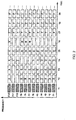
- Fig. 2 is a diagram illustrating allocation of communication slots in some frame. Similar to the conventional technology, slots with oblique lines are broadcast slots received by all terminals and the terminals A to F perform communication using indicated slots respectively.
- processing is performed by assuming that the number of subcarriers used is odd so that the processing can be made easier to understand. However, there is no inevitability for this assumption and, if an even number of subcarriers are used for processing, the center frequency will be a frequency at which no subcarrier exists and no problem will be caused by arranging in advance which subcarrier to use as the center subcarrier between the transmitting and receiving apparatuses.
- subcarriers not used for modulation are arranged. More specifically, the subcarrier numbers not used for modulation are zero, 385 to 511, -385 to -512, and 32 X p (p is an integer between -12 and 12).
- slots to be used are five slots of (T2 to T6, F12) and the frequency channel is F12 only.
- f(321) to f (384) are allocated to F12 and it is assumed that the subcarrier with the maximum number f(384) and the subcarrier f(352) positioned in the center after excluding f(384) are not to be used.
- slots to be used are nine slots of (T2, F7 to F9) and (T5 to T6, F7 to F9).
- Subcarriers to be used for F7 to F9 are f(1) to f(192) and it is assumed that the subcarrier with the maximum number f(192) and the subcarrier f(96) positioned in the center after excluding f(192) are not to be used.
- C uses 10 slots of (T3, F1 to F10).
- Subcarriers to be used are f(-384) to f(256). If subcarriers to be accessed sandwich f(0), processing not to use a subcarrier with the maximum number is not performed. Thus, only the subcarrier f(-64) positioned in the center is not to be used. f(0) is naturally not used.
- D uses 18 slots of (T2, F1 to F6) and (T4 to T5, F1 to F6).
- Subcarriers to be used are f(-384) to F(-1).
- the subcarrier f(-1) with the maximum number and the subcarrier f(-193) positioned in the center are not to be used.
- E uses 4 slots of (T4 to T5, F10 to F11).
- Subcarriers to be used are f(193) to F(320).
- the subcarrier f(320) with the maximum number and the subcarrier f(256) positioned in the center are not to be used.
- F uses 36 slots of (T7 to T9, F1 to F12).
- Subcarriers to be used are f(-384) to F(384). Only the subcarrier f(0) positioned in the center is not to be used.
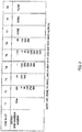
- Fig. 3 summarizes unused subcarriers in units of time slots. As is evident from Fig. 3 , the number of unused subcarriers has decreased in comparison with the first embodiment and terminals capable of accessing all bands can use exactly as many subcarriers as before. Continuous bands are allocated to slots in Fig. 2 and even if an unused slot is present therebetween, no problem will be caused by performing processing under the assumption that a band thereof is being used.
- Fig. 4 is a block diagram illustrating the schematic configuration of a transmitting circuit according to the second embodiment.
- the transmitting circuit according to the second embodiment additionally has the unused subcarrier operation part 11.
- the unused subcarrier operation part 11 carries out a function to operate unused subcarriers described above.
- the slot number, the terminal ID using the slot, and the maximum number and minimum number of the sub-channel number to be used are input into the unused subcarrier operation part 11.
- Fig. 5 is a flow chart illustrating operations of the unused subcarrier operation part 11. Parameters used in Fig. 5 are the same as those described above. However, fdc is an index value showing whether or not a channel used contains a DC component, TS is a variable value of the slot number, and m_max and m_min are the maximum value and minimum value of the sub-channel to be input into the unused subcarrier operation part 11 for use respectively.
- TS 0 are set.
- S102 TS is incremented by one.
- TS is equal to or greater than 2
- proceed to S105 whether in applicable TS there is a terminal to which a slot should be allocated is determined. If there is such a terminal, proceed to S106, and if there is no such terminal, proceed to S110.
- an fdc operation is performed. fdc is an operation based on the subcarrier number.
- whether sub-channels are allocated by sandwiching f(0) is determined based on the value of fdc. If fdc is negative, proceed to S109 because sub-channels are allocated by sandwiching f(0). If fdc is positive, proceed to S108.
- S108 is a process to determine unused subcarriers when f (0) is not sandwiched and the subcarrier f (m_max) with the maximum value and the center subcarrier f((m_max + m_min -1)/2) in the band excluding f(m_max) are set to zero respectively.
- S109 is a process to determine unused subcarriers when f(0) is sandwiched and the subcarrier f((m_max + m_min -1)/2) to be the center in the band is set to zero.
- Unused subcarriers are determined in the first and second embodiments under the assumption that an influence of DC noise of a reception apparatus is always considerable, but existence of a terminal with very good characteristics can also be considered.
- the introduction of a function to determine unused subcarriers to eliminate an influence of the DC noise in the reception apparatus can also be considered when a request is made from a terminal.
- base station equipment can be configured by a transmitting circuit according to the present embodiments. With this base station equipment, it becomes possible to prevent deterioration of communication characteristics and occurrence of errors in receiving slots to avoid degradation of throughput because the DC component will not exert any influence upon transmission and reception processing even if communication is performed with a terminal whose bandwidth in use is limited in order to reduce power consumption.
Applications Claiming Priority (4)
| Application Number | Priority Date | Filing Date | Title |
|---|---|---|---|
| JP2004317364 | 2004-10-29 | ||
| EP14161791.0A EP2750312B1 (fr) | 2004-10-29 | 2005-10-28 | Procédé de communication et transmetteur radio |
| PCT/JP2005/019898 WO2006046696A1 (fr) | 2004-10-29 | 2005-10-28 | Méthode de communication et émetteur radio |
| EP05799403A EP1814251A4 (fr) | 2004-10-29 | 2005-10-28 | Méthode de communication et émetteur radio |
Related Parent Applications (2)
| Application Number | Title | Priority Date | Filing Date |
|---|---|---|---|
| EP14161791.0A Division EP2750312B1 (fr) | 2004-10-29 | 2005-10-28 | Procédé de communication et transmetteur radio |
| EP05799403A Division EP1814251A4 (fr) | 2004-10-29 | 2005-10-28 | Méthode de communication et émetteur radio |
Publications (2)
| Publication Number | Publication Date |
|---|---|
| EP3364573A1 true EP3364573A1 (fr) | 2018-08-22 |
| EP3364573B1 EP3364573B1 (fr) | 2024-03-20 |
Family
ID=36227936
Family Applications (3)
| Application Number | Title | Priority Date | Filing Date |
|---|---|---|---|
| EP05799403A Withdrawn EP1814251A4 (fr) | 2004-10-29 | 2005-10-28 | Méthode de communication et émetteur radio |
| EP18165377.5A Active EP3364573B1 (fr) | 2004-10-29 | 2005-10-28 | Procédé de communication et transmetteur radio |
| EP14161791.0A Active EP2750312B1 (fr) | 2004-10-29 | 2005-10-28 | Procédé de communication et transmetteur radio |
Family Applications Before (1)
| Application Number | Title | Priority Date | Filing Date |
|---|---|---|---|
| EP05799403A Withdrawn EP1814251A4 (fr) | 2004-10-29 | 2005-10-28 | Méthode de communication et émetteur radio |
Family Applications After (1)
| Application Number | Title | Priority Date | Filing Date |
|---|---|---|---|
| EP14161791.0A Active EP2750312B1 (fr) | 2004-10-29 | 2005-10-28 | Procédé de communication et transmetteur radio |
Country Status (6)
| Country | Link |
|---|---|
| US (9) | US8488688B2 (fr) |
| EP (3) | EP1814251A4 (fr) |
| JP (5) | JP4658959B2 (fr) |
| CN (3) | CN102868510B (fr) |
| DE (1) | DE202005022046U1 (fr) |
| WO (1) | WO2006046696A1 (fr) |
Families Citing this family (24)
| Publication number | Priority date | Publication date | Assignee | Title |
|---|---|---|---|---|
| EP1814251A4 (fr) | 2004-10-29 | 2012-06-27 | Sharp Kk | Méthode de communication et émetteur radio |
| US8150442B2 (en) | 2005-01-18 | 2012-04-03 | Sharp Kabushiki Kaisha | Method and apparatus for controlling power of subcarriers in a wireless communication system |
| JP4533833B2 (ja) * | 2005-10-31 | 2010-09-01 | 株式会社東芝 | 無線通信装置及び同期用シンボルにおける信号−サブキャリア割り当て方法 |
| JP4845644B2 (ja) * | 2006-08-29 | 2011-12-28 | 三洋電機株式会社 | 通信方法およびそれを利用した無線装置 |
| CN101136894B (zh) * | 2007-03-23 | 2012-11-28 | 中兴通讯股份有限公司 | 可扩展的ofdm及ofdma带宽分配的方法和系统 |
| CN104660389B (zh) | 2007-08-13 | 2018-04-03 | 夏普株式会社 | 基站装置、通信装置、通信方法和通信系统 |
| JP4548487B2 (ja) * | 2008-01-11 | 2010-09-22 | ソニー株式会社 | 送信装置、通信システム、送信方法及びプログラム |
| EP2249498A1 (fr) | 2008-03-05 | 2010-11-10 | Sharp Kabushiki Kaisha | Système de communication, dispositif de communication, et procédé de communication |
| US8687726B2 (en) * | 2009-11-09 | 2014-04-01 | Time Reversal Communications | Method for transmitting digital data, and transmitter base implementing such a method |
| JP2012060484A (ja) * | 2010-09-10 | 2012-03-22 | Fujitsu Ltd | Ofdm送信データチェック方法及びofdm通信装置 |
| WO2014167927A1 (fr) * | 2013-04-12 | 2014-10-16 | 三菱電機株式会社 | Appareil de communication et procédé de réception |
| EP3036874A4 (fr) * | 2013-08-24 | 2017-01-04 | Indian Institute of Technology Delhi | Multiplexage par répartition en fréquence de rapport de puissance maximale sur puissance moyenne pouvant être réglé |
| EP3044885A1 (fr) * | 2013-09-13 | 2016-07-20 | Hewlett Packard Enterprise Development LP | Réaffectation de puissance de sous-porteuses |
| US9825678B2 (en) | 2013-11-26 | 2017-11-21 | Marvell World Trade Ltd. | Uplink multi-user multiple input multiple output for wireless local area network |
| WO2015081269A1 (fr) * | 2013-11-27 | 2015-06-04 | Marvell Semiconductor, Inc. | Sondage et allocation de blocs de tonalité pour un accès multiple par répartition orthogonale de fréquence (ofdma) dans des réseaux locaux sans fil |
| US9166660B2 (en) | 2013-11-27 | 2015-10-20 | Marvell World Trade Ltd. | Uplink multi-user multiple input multiple output beamforming |
| KR20160148687A (ko) | 2014-05-02 | 2016-12-26 | 마벨 월드 트레이드 리미티드 | 무선 통신 네트워크에서의 다중 사용자 할당 시그널링 |
| CN106162906B (zh) | 2015-03-31 | 2019-01-15 | 中兴通讯股份有限公司 | 调度信息发送、接收方法及装置 |
| CN105072066B (zh) * | 2015-07-21 | 2018-06-15 | 南方科技大学 | 一种带有保护间隔信号的无线信能同传方法及系统 |
| WO2017056796A1 (fr) * | 2015-10-01 | 2017-04-06 | ソニー株式会社 | Dispositif, procédé et programme |
| WO2017135799A1 (fr) * | 2016-02-05 | 2017-08-10 | Samsung Electronics Co., Ltd. | Procédé d'accès multiple, et procédé de transmission, récepteur et émetteur correspondants |
| US10893477B2 (en) * | 2018-06-20 | 2021-01-12 | Silicon Laboratories Inc. | Same-channel interference detection and early receiver powerdown for OFDM signal processor |
| KR102528624B1 (ko) | 2019-04-12 | 2023-05-04 | 삼성전자 주식회사 | 무선 통신 시스템에서 로컬 주파수를 결정하는 방법 및 장치 |
| CN111404561B (zh) * | 2020-03-10 | 2022-03-29 | Oppo广东移动通信有限公司 | 基于资源块分推的信号发射方法及相关产品 |
Citations (4)
| Publication number | Priority date | Publication date | Assignee | Title |
|---|---|---|---|---|
| JPH10276165A (ja) | 1997-03-27 | 1998-10-13 | Sanyo Electric Co Ltd | Ofdm信号受信機 |
| JPH11154925A (ja) | 1997-11-21 | 1999-06-08 | Hitachi Denshi Ltd | ディジタル伝送装置 |
| JPH11346203A (ja) | 1998-06-02 | 1999-12-14 | Matsushita Electric Ind Co Ltd | Ofdma信号伝送装置及び方法 |
| US20030224731A1 (en) * | 2002-02-21 | 2003-12-04 | Sony Corporation | Radio communication method, radio communication system, radio communication base station, radio communication terminal station, and radio communication program |
Family Cites Families (148)
| Publication number | Priority date | Publication date | Assignee | Title |
|---|---|---|---|---|
| US4122415A (en) * | 1977-03-21 | 1978-10-24 | Rca Corporation | AM transmitter with an offset voltage to the RF stage to compensate for switching time of the modulators |
| JPH01127231A (ja) | 1987-11-11 | 1989-05-19 | Hoden Seimitsu Kako Kenkyusho Ltd | ワイヤ放電加工機のワイヤ廃棄処理装置 |
| US6334219B1 (en) * | 1994-09-26 | 2001-12-25 | Adc Telecommunications Inc. | Channel selection for a hybrid fiber coax network |
| US5621723A (en) | 1994-09-27 | 1997-04-15 | Gte Laboratories Incorporated | Power control in a CDMA network |
| US20010055320A1 (en) | 1994-12-15 | 2001-12-27 | Pierzga Wayne Francis | Multiplex communication |
| US5857153A (en) | 1995-10-13 | 1999-01-05 | Telefonaktiebolaget Lm Ericsson (Publ) | Cellular telecommunications network having seamless interoperability between exchanges while providing voice, asynchronous data and facsimile services in multiple frequency hyperbands |
| JP3780551B2 (ja) | 1996-01-29 | 2006-05-31 | ソニー株式会社 | 多元接続による信号送信方法及び装置 |
| US6035000A (en) | 1996-04-19 | 2000-03-07 | Amati Communications Corporation | Mitigating radio frequency interference in multi-carrier transmission systems |
| US5995567A (en) | 1996-04-19 | 1999-11-30 | Texas Instruments Incorporated | Radio frequency noise canceller |
| US6014412A (en) | 1996-04-19 | 2000-01-11 | Amati Communications Corporation | Digital radio frequency interference canceller |
| JPH1066039A (ja) | 1996-08-23 | 1998-03-06 | Sony Corp | 通信方法、送信装置、送信方法、受信装置及び受信方法 |
| JP2001359152A (ja) | 2000-06-14 | 2001-12-26 | Sony Corp | 無線通信システム、無線基地局装置、無線移動局装置、無線ゾーン割当て方法及び無線通信方法 |
| JP4040125B2 (ja) | 1996-09-18 | 2008-01-30 | ソニー株式会社 | 音声信号記録装置 |
| US6061568A (en) | 1996-10-01 | 2000-05-09 | Ericsson Inc. | Method and apparatus for mitigating intermodulation effects in multiple-signal transmission systems |
| JPH10190612A (ja) | 1996-12-26 | 1998-07-21 | Sony Corp | 通信方法及び受信装置 |
| JPH10191431A (ja) * | 1996-12-26 | 1998-07-21 | Sony Corp | 通信方法、基地局及び端末装置 |
| JP3565537B2 (ja) | 1997-06-18 | 2004-09-15 | 株式会社日立国際電気 | 直交周波数分割多重変調信号の伝送方式 |
| JP3670445B2 (ja) * | 1997-06-30 | 2005-07-13 | 株式会社東芝 | 無線通信システム |
| JP3615909B2 (ja) | 1997-06-30 | 2005-02-02 | 三菱重工業株式会社 | 移動物体検出装置 |
| EP0899923A1 (fr) | 1997-08-29 | 1999-03-03 | Sony International (Europe) GmbH | Transmission de signaux de réglage de puissance dans un système à modulation multiporteuse |
| DE69733313T2 (de) | 1997-11-07 | 2006-01-19 | Sony International (Europe) Gmbh | Mehrträgerübertragung, kompatibel zum existierenden GSM-System |
| JP3778397B2 (ja) | 1997-12-27 | 2006-05-24 | ソニー株式会社 | 送信方法、送信電力制御方法及び基地局装置 |
| JPH11205276A (ja) * | 1998-01-20 | 1999-07-30 | Nippon Telegr & Teleph Corp <Ntt> | マルチキャリア変調装置 |
| EP1072136B1 (fr) | 1998-04-14 | 2002-01-16 | Fraunhofer-Gesellschaft zur Förderung der angewandten Forschung e.V. | Correction d'erreur de phase d'echo dans un systeme a porteuses multiples |
| JP3957882B2 (ja) | 1998-06-17 | 2007-08-15 | 株式会社日立コミュニケーションテクノロジー | 電力制御方法及び電力制御装置 |
| JP4287536B2 (ja) | 1998-11-06 | 2009-07-01 | パナソニック株式会社 | Ofdm送受信装置及びofdm送受信方法 |
| US6741551B1 (en) | 1999-01-11 | 2004-05-25 | International Business Machines Corporation | Hybrid TDMA/CDMA system based on filtered multitone modulation |
| JP2000354266A (ja) | 1999-06-11 | 2000-12-19 | Sony Corp | 無線通信端末装置 |
| JP4315530B2 (ja) * | 1999-07-29 | 2009-08-19 | 富士通株式会社 | 非接触icカードデバイスのための検波回路 |
| JP2001238251A (ja) | 2000-02-23 | 2001-08-31 | Nec Corp | セルラシステムの隣接キャリア周波数干渉回避方法、移動局、及び基地局制御装置 |
| JP4323669B2 (ja) | 2000-03-15 | 2009-09-02 | パナソニック株式会社 | データ伝送装置及びデータ伝送方法 |
| JP2001313628A (ja) * | 2000-04-28 | 2001-11-09 | Sony Corp | Ofdm受信装置及び方法 |
| US7013145B1 (en) | 2000-08-22 | 2006-03-14 | Cellco Partnership | Methods and apparatus for utilizing radio frequency spectrum simultaneously and concurrently in the presence of co-channel and/or adjacent channel television signals by adjusting transmitter power or receiver sensitivity |
| US7009931B2 (en) | 2000-09-01 | 2006-03-07 | Nortel Networks Limited | Synchronization in a multiple-input/multiple-output (MIMO) orthogonal frequency division multiplexing (OFDM) system for wireless applications |
| US6834079B1 (en) | 2000-10-20 | 2004-12-21 | 3Com Corporation | Efficient implementation for equalization of multicarrier channels |
| JP3550085B2 (ja) | 2000-11-01 | 2004-08-04 | 松下電器産業株式会社 | 無線送信装置および無線送信方法 |
| US6947748B2 (en) | 2000-12-15 | 2005-09-20 | Adaptix, Inc. | OFDMA with adaptive subcarrier-cluster configuration and selective loading |
| US7054375B2 (en) | 2000-12-22 | 2006-05-30 | Nokia Corporation | Method and apparatus for error reduction in an orthogonal modulation system |
| JP4242553B2 (ja) * | 2000-12-28 | 2009-03-25 | ヤマハ株式会社 | ディジタルオーディオ信号録音装置 |
| US20020085641A1 (en) | 2000-12-29 | 2002-07-04 | Motorola, Inc | Method and system for interference averaging in a wireless communication system |
| US7002934B2 (en) | 2001-01-22 | 2006-02-21 | Unique Broadband Systems, Inc. | OFDM multiple upstream receiver network |
| JP3800503B2 (ja) * | 2001-04-24 | 2006-07-26 | 日本ビクター株式会社 | マルチキャリア信号の生成方法 |
| JP4496673B2 (ja) | 2001-06-07 | 2010-07-07 | 株式会社デンソー | Ofdm方式の送受信機 |
| US7206350B2 (en) | 2001-06-11 | 2007-04-17 | Unique Broadband Systems, Inc. | OFDM multiple sub-channel communication system |
| US7594010B2 (en) | 2001-06-28 | 2009-09-22 | King's London College | Virtual antenna array |
| JP2004357339A (ja) * | 2001-06-29 | 2004-12-16 | Matsushita Electric Ind Co Ltd | マルチキャリア送信装置、マルチキャリア受信装置およびマルチキャリア無線通信方法 |
| JP2003087218A (ja) * | 2001-06-29 | 2003-03-20 | Matsushita Electric Ind Co Ltd | マルチキャリア送信装置、マルチキャリア受信装置およびマルチキャリア無線通信方法 |
| JP3607643B2 (ja) | 2001-07-13 | 2005-01-05 | 松下電器産業株式会社 | マルチキャリア送信装置、マルチキャリア受信装置、およびマルチキャリア無線通信方法 |
| US7272175B2 (en) | 2001-08-16 | 2007-09-18 | Dsp Group Inc. | Digital phase locked loop |
| US20030039226A1 (en) | 2001-08-24 | 2003-02-27 | Kwak Joseph A. | Physical layer automatic repeat request (ARQ) |
| TWI261984B (en) | 2001-08-24 | 2006-09-11 | Interdigital Tech Corp | Implementing a physical layer automatic repeat request for a subscriber unit |
| JPWO2003021809A1 (ja) | 2001-09-03 | 2004-12-24 | 三菱電機株式会社 | 無線移動機における送信電力制御方法 |
| JP2003101499A (ja) | 2001-09-25 | 2003-04-04 | Victor Co Of Japan Ltd | マルチキャリア信号の生成方法、マルチキャリア信号の復号方法、マルチキャリア信号生成装置、及びマルチキャリア信号復号装置 |
| US7289476B2 (en) | 2001-10-16 | 2007-10-30 | Nokia Corporation | Method and system to increase QoS and range in a multicarrier system |
| US6563885B1 (en) | 2001-10-24 | 2003-05-13 | Texas Instruments Incorporated | Decimated noise estimation and/or beamforming for wireless communications |
| US20030093526A1 (en) | 2001-11-13 | 2003-05-15 | Koninklijke Philips Electronics N. V. | Apparatus and method for providing quality of service signaling for wireless mac layer |
| JP3875079B2 (ja) * | 2001-11-16 | 2007-01-31 | ソフトバンクテレコム株式会社 | 直交周波数分割多重システムおよび送受信装置 |
| JP3727283B2 (ja) * | 2001-11-26 | 2005-12-14 | 松下電器産業株式会社 | 無線送信装置、無線受信装置及び無線送信方法 |
| JP3875086B2 (ja) | 2001-11-30 | 2007-01-31 | ソフトバンクテレコム株式会社 | 直交周波数分割多重システムおよび送受信装置 |
| US7304939B2 (en) * | 2001-12-03 | 2007-12-04 | Nortel Networks Limited | Communication using simultaneous orthogonal signals |
| JP2003259448A (ja) | 2002-02-28 | 2003-09-12 | Sony Corp | 無線通信方法、無線通信システム、無線基地局、無線通信端末、プログラム及び媒体 |
| US7630403B2 (en) | 2002-03-08 | 2009-12-08 | Texas Instruments Incorporated | MAC aggregation frame with MSDU and fragment of MSDU |
| KR100790114B1 (ko) * | 2002-03-16 | 2007-12-31 | 삼성전자주식회사 | 직교주파수 분할다중 접속 시스템에서 적응적 파일럿반송파 할당 방법 및 장치 |
| US7224704B2 (en) | 2002-04-01 | 2007-05-29 | Texas Instruments Incorporated | Wireless network scheduling data frames including physical layer configuration |
| AU2003226934A1 (en) | 2002-04-10 | 2003-10-27 | Disop-Nordic Holding Aps | Tube with self-closing mechanism for liquid container |
| US20030193889A1 (en) | 2002-04-11 | 2003-10-16 | Intel Corporation | Wireless device and method for interference and channel adaptation in an OFDM communication system |
| JP2003309533A (ja) | 2002-04-17 | 2003-10-31 | Matsushita Electric Ind Co Ltd | 無線送信装置、無線受信装置及びその方法 |
| JP3893078B2 (ja) * | 2002-05-08 | 2007-03-14 | 三星電子株式会社 | マルチチャンネル受信機 |
| JP2003333008A (ja) | 2002-05-10 | 2003-11-21 | Sony Corp | 通信システムおよびその方法、受信装置およびその方法、通信装置およびその方法、ならびにプログラム |
| US7200178B2 (en) | 2002-06-12 | 2007-04-03 | Texas Instruments Incorporated | Methods for optimizing time variant communication channels |
| US7095709B2 (en) | 2002-06-24 | 2006-08-22 | Qualcomm, Incorporated | Diversity transmission modes for MIMO OFDM communication systems |
| GB0215727D0 (en) * | 2002-07-06 | 2002-08-14 | Lucas Industries Ltd | No-back device |
| EP1542384A4 (fr) | 2002-08-28 | 2007-06-20 | Fujitsu Ltd | Appareil de transmission/reception et procede de transmission/reception |
| DE10239810A1 (de) | 2002-08-29 | 2004-03-11 | Siemens Ag | Verfahren und Sendeeinrichtung zum Übertragen von Daten in einem Mehrträgersystem |
| JP4115784B2 (ja) * | 2002-09-11 | 2008-07-09 | 三菱電機株式会社 | 再送制御方法および通信装置 |
| US20050105593A1 (en) | 2002-10-07 | 2005-05-19 | Takashi Dateki | Transmission power control method and transmission power control apparatus in OFDM-CDMA |
| JP3732830B2 (ja) | 2002-10-10 | 2006-01-11 | 松下電器産業株式会社 | マルチキャリア送信装置及びマルチキャリア送信方法 |
| US7324429B2 (en) | 2002-10-25 | 2008-01-29 | Qualcomm, Incorporated | Multi-mode terminal in a wireless MIMO system |
| US6928062B2 (en) | 2002-10-29 | 2005-08-09 | Qualcomm, Incorporated | Uplink pilot and signaling transmission in wireless communication systems |
| US7039001B2 (en) | 2002-10-29 | 2006-05-02 | Qualcomm, Incorporated | Channel estimation for OFDM communication systems |
| WO2004047348A1 (fr) | 2002-11-20 | 2004-06-03 | Ntt Docomo, Inc. | Systeme et procede de communication, dispositif d'emission, dispositif de reception et programme de commande |
| KR100511559B1 (ko) | 2002-11-28 | 2005-08-31 | 한국전자통신연구원 | 시변 채널 왜곡 제거 기능을 가지는 주파수 분할 다중시스템에서의 송수신 방법 |
| US7027527B2 (en) | 2002-12-04 | 2006-04-11 | Motorola, Inc. | Excess delay spread detection method for multi-carrier communication systems |
| JP4154229B2 (ja) | 2002-12-27 | 2008-09-24 | 富士通株式会社 | 適応アレーアンテナ制御装置 |
| CN101997589B (zh) * | 2003-01-23 | 2013-05-29 | 高通股份有限公司 | 在多址无线通信系统中提供发射分集的方法和装置 |
| US7277493B2 (en) | 2003-01-28 | 2007-10-02 | Agere Systems Inc. | Equalization in orthogonal frequency domain multiplexing |
| US7756002B2 (en) * | 2003-01-30 | 2010-07-13 | Texas Instruments Incorporated | Time-frequency interleaved orthogonal frequency division multiplexing ultra wide band physical layer |
| JP4163018B2 (ja) | 2003-02-03 | 2008-10-08 | Kddi株式会社 | 伝送路特性推定装置および伝送路特性推定方法、無線復調装置、コンピュータプログラム |
| US8422434B2 (en) | 2003-02-18 | 2013-04-16 | Qualcomm Incorporated | Peak-to-average power ratio management for multi-carrier modulation in wireless communication systems |
| JP4131177B2 (ja) | 2003-02-27 | 2008-08-13 | 株式会社デンソー | 無線通信システムおよび通信局 |
| US7983355B2 (en) * | 2003-07-09 | 2011-07-19 | Broadcom Corporation | System and method for RF signal combining and adaptive bit loading for data rate maximization in multi-antenna communication systems |
| US7142864B2 (en) | 2003-04-23 | 2006-11-28 | Qualcomm, Incorporated | Methods and apparatus of enhancing performance in wireless communication systems |
| US7640373B2 (en) | 2003-04-25 | 2009-12-29 | Motorola, Inc. | Method and apparatus for channel quality feedback within a communication system |
| US20040213185A1 (en) | 2003-04-25 | 2004-10-28 | Seong-Jun Oh | System and method of controlling forward link transmit power |
| US8477592B2 (en) * | 2003-05-14 | 2013-07-02 | Qualcomm Incorporated | Interference and noise estimation in an OFDM system |
| JP3847733B2 (ja) | 2003-06-12 | 2006-11-22 | 松下電器産業株式会社 | マルチキャリア通信方法及びその通信装置 |
| KR20050000709A (ko) | 2003-06-24 | 2005-01-06 | 삼성전자주식회사 | 다중 접속 방식을 사용하는 통신 시스템의 데이터 송수신장치 및 방법 |
| DE10336312B4 (de) | 2003-08-07 | 2007-08-30 | Siemens Ag | Verfahren zur Synchronisation eines in Funkzellen aufgeteilten Funkkommunikationssystems, sowie eine Basis- und Mobilstation in einem derartigen System |
| EP1653646B1 (fr) | 2003-08-20 | 2019-03-06 | Panasonic Corporation | Dispositif de communication radio et procédé d'attribution de sous-porteuses |
| US7702037B2 (en) * | 2003-08-26 | 2010-04-20 | Agere Systems Inc. | Method and apparatus for estimating DC offset in an orthogonal frequency division multiplexing system |
| US7230942B2 (en) | 2003-10-03 | 2007-06-12 | Qualcomm, Incorporated | Method of downlink resource allocation in a sectorized environment |
| KR100561472B1 (ko) | 2003-10-21 | 2006-03-16 | 삼성전자주식회사 | 다중 신호를 포괄하여 송수신하는 장치 및 방법 |
| KR101015736B1 (ko) | 2003-11-19 | 2011-02-22 | 삼성전자주식회사 | 직교 주파수 분할 다중 방식의 이동통신 시스템에서선택적 전력 제어 장치 및 방법 |
| KR100566274B1 (ko) | 2003-11-20 | 2006-03-30 | 삼성전자주식회사 | 직교주파수분할다중 시스템에서 부반송파 할당 장치 및방법 |
| KR100507541B1 (ko) | 2003-12-19 | 2005-08-09 | 삼성전자주식회사 | 직교주파수분할다중접속 시스템에서의 데이터 및 파일롯할당 방법 과 그를 이용한 송신 방법 및 그 장치, 수신방법과 그 장치 |
| KR100534594B1 (ko) | 2003-12-27 | 2005-12-07 | 한국전자통신연구원 | 다중반송파 코드분할다중접속 시스템에서 적응형 하향링크패킷 전송방법 |
| JP4043442B2 (ja) | 2004-01-09 | 2008-02-06 | 株式会社東芝 | 無線送信装置、無線受信装置、無線送信方法及び無線受信方法、無線通信システム |
| TWI305092B (en) | 2004-01-13 | 2009-01-01 | Interdigital Tech Corp | Orthogonal frequency division multiplexing (ofdm) method and apparatus for protecting and authenticating wirelessly transmitted digital information |
| KR20050075477A (ko) | 2004-01-15 | 2005-07-21 | 삼성전자주식회사 | Mimo 스테이션 간에 통신하는 방법 |
| US7519035B2 (en) | 2004-02-23 | 2009-04-14 | Sharp Laboratories Of America, Inc. | Method to negotiate consumed power versus medium occupancy time in MIMO based WLAN systems using admission control |
| KR100922950B1 (ko) * | 2004-03-05 | 2009-10-22 | 삼성전자주식회사 | 직교주파수분할다중접속 방식을 기반으로 하는 이동통신시스템에서 데이터 프레임 처리 결과 송/수신장치 및 방법 |
| US7826435B1 (en) | 2004-03-05 | 2010-11-02 | Zte (Usa) Inc. | Power control in OFDM and OFDMA wireless communication networks |
| JP2005260337A (ja) * | 2004-03-09 | 2005-09-22 | Renesas Technology Corp | 復調回路および無線通信システム |
| US7509047B2 (en) * | 2004-03-12 | 2009-03-24 | Futurewei Technologies, Inc. | System and method for subcarrier modulation in ISM band as supervisory channel |
| KR100946923B1 (ko) * | 2004-03-12 | 2010-03-09 | 삼성전자주식회사 | 직교 주파수 분할 다중 방식을 사용하는 통신 시스템에서 채널 품질 정보의 송수신 장치 및 방법, 그리고 그에 따른 시스템 |
| US7447268B2 (en) | 2004-03-31 | 2008-11-04 | Intel Corporation | OFDM system with per subcarrier phase rotation |
| JP2004254335A (ja) * | 2004-04-02 | 2004-09-09 | Toshiba Corp | 無線基地局、無線端末 |
| US7417974B2 (en) * | 2004-04-14 | 2008-08-26 | Broadcom Corporation | Transmitting high rate data within a MIMO WLAN |
| KR100663489B1 (ko) | 2004-04-16 | 2007-01-02 | 삼성전자주식회사 | 직교 분할 다중 접속 시스템에서 셀 검출 방법 및 장치 |
| US7047006B2 (en) | 2004-04-28 | 2006-05-16 | Motorola, Inc. | Method and apparatus for transmission and reception of narrowband signals within a wideband communication system |
| JP4515155B2 (ja) | 2004-05-25 | 2010-07-28 | 株式会社エヌ・ティ・ティ・ドコモ | 送信装置 |
| US7580630B2 (en) | 2004-06-07 | 2009-08-25 | Nortel Networks Limited | Spectral shaping for optical OFDM transmission |
| US8014781B2 (en) | 2004-06-08 | 2011-09-06 | Qualcomm Incorporated | Intra-cell common reuse for a wireless communications system |
| EP3537681B1 (fr) | 2004-06-24 | 2020-10-07 | Apple Inc. | Préambules dans un système ofdma |
| JP2008505567A (ja) | 2004-07-01 | 2008-02-21 | テキサス インスツルメンツ インコーポレイテッド | スペクトル・スカルプティングを可能にする多帯域ofdmシステムの時間領域ウィンドイング |
| US8891349B2 (en) | 2004-07-23 | 2014-11-18 | Qualcomm Incorporated | Method of optimizing portions of a frame |
| US7333456B2 (en) | 2004-08-02 | 2008-02-19 | Beceem Communications Inc. | Training information transmission method in a block transmission system |
| US8484272B2 (en) * | 2004-08-20 | 2013-07-09 | Qualcomm Incorporated | Unified pulse shaping for multi-carrier and single-carrier waveforms |
| US20060045192A1 (en) | 2004-08-25 | 2006-03-02 | Hiroshi Hayashi | Method and apparatus for pilot channel transmission and reception within a multi-carrier communication system |
| US7593472B2 (en) * | 2004-10-22 | 2009-09-22 | Integrated System Solution Corp. | Methods and apparatus for circulation transmissions for OFDM-based MIMO systems |
| KR100974326B1 (ko) * | 2004-10-28 | 2010-08-05 | 삼성전자주식회사 | 직교 주파수 분할 다중 접속 방식을 사용하는 통신시스템에서 동적 자원 할당 장치 및 방법 |
| EP1814251A4 (fr) | 2004-10-29 | 2012-06-27 | Sharp Kk | Méthode de communication et émetteur radio |
| WO2006062428A1 (fr) | 2004-11-29 | 2006-06-15 | Intel Corporation | Procede et systeme pour la communication par ondes porteuses multiples entre une station de base et des abonnes de differentes bandes passantes |
| US7573851B2 (en) | 2004-12-07 | 2009-08-11 | Adaptix, Inc. | Method and system for switching antenna and channel assignments in broadband wireless networks |
| US7519845B2 (en) | 2005-01-05 | 2009-04-14 | Microsoft Corporation | Software-based audio rendering |
| US8150442B2 (en) | 2005-01-18 | 2012-04-03 | Sharp Kabushiki Kaisha | Method and apparatus for controlling power of subcarriers in a wireless communication system |
| US7809342B2 (en) * | 2005-02-08 | 2010-10-05 | E-Radio Usa, Inc. | Systems and methods for providing product information over a carrier wave |
| JPWO2006107037A1 (ja) | 2005-04-04 | 2008-09-25 | 日本電気株式会社 | Ofdm通信システム、そのフィードバック情報生成方法、および通信装置 |
| US7860174B2 (en) | 2005-05-31 | 2010-12-28 | Agere Systems Inc. | Method and apparatus for frequency domain compensation of DC offset in an orthogonal frequency division multiplexing system |
| US20070004465A1 (en) | 2005-06-29 | 2007-01-04 | Aris Papasakellariou | Pilot Channel Design for Communication Systems |
| US7983350B1 (en) | 2005-10-25 | 2011-07-19 | Altera Corporation | Downlink subchannelization module |
| EP1950900A4 (fr) | 2005-10-28 | 2010-01-20 | Sharp Kk | Emetteur, systeme de communication et procede d emission |
| KR100877750B1 (ko) | 2006-12-27 | 2009-01-12 | 포스데이타 주식회사 | 직교주파수 분할 다중 접속 시스템의 파일럿 톤 생성 방법및 장치와 이를 이용한 채널추정 방법 및 장치 |
| US8131218B2 (en) * | 2007-04-13 | 2012-03-06 | General Dynamics C4 Systems, Inc. | Methods and apparatus for wirelessly communicating signals that include embedded synchronization/pilot sequences |
| US8086250B2 (en) | 2009-02-03 | 2011-12-27 | Integrity Tracking, Llc | Communications method |
| US8447265B2 (en) | 2009-02-03 | 2013-05-21 | Integrity Tracking, Llc | Proximity based emergency communication system |
| US20100309046A1 (en) | 2009-02-03 | 2010-12-09 | Integrity Tracking, Llc | Communications method |
| US8270938B2 (en) | 2009-02-03 | 2012-09-18 | Integrity Tracking, Llc | Managing battery power for mobile emergency communication device |
-
2005
- 2005-10-28 EP EP05799403A patent/EP1814251A4/fr not_active Withdrawn
- 2005-10-28 CN CN201210359307.1A patent/CN102868510B/zh not_active Ceased
- 2005-10-28 CN CN2005800371710A patent/CN101048960B/zh active Active
- 2005-10-28 CN CN201210359331.5A patent/CN102868511B/zh not_active Ceased
- 2005-10-28 DE DE202005022046U patent/DE202005022046U1/de not_active Expired - Lifetime
- 2005-10-28 US US11/666,239 patent/US8488688B2/en active Active
- 2005-10-28 WO PCT/JP2005/019898 patent/WO2006046696A1/fr active Application Filing
- 2005-10-28 JP JP2006542341A patent/JP4658959B2/ja active Active
- 2005-10-28 EP EP18165377.5A patent/EP3364573B1/fr active Active
- 2005-10-28 EP EP14161791.0A patent/EP2750312B1/fr active Active
-
2009
- 2009-10-09 JP JP2009235592A patent/JP4701300B2/ja active Active
-
2010
- 2010-11-22 JP JP2010260647A patent/JP5123368B2/ja active Active
-
2011
- 2011-10-12 US US13/271,936 patent/US8325838B2/en active Active
- 2011-10-21 US US13/278,437 patent/US8391386B2/en active Active
-
2012
- 2012-04-27 JP JP2012103546A patent/JP5063825B2/ja active Active
- 2012-06-21 JP JP2012139719A patent/JP5379269B2/ja active Active
-
2013
- 2013-06-12 US US13/915,792 patent/US8855077B2/en active Active
-
2014
- 2014-08-13 US US14/459,061 patent/US9148874B2/en active Active
-
2015
- 2015-08-27 US US14/837,056 patent/US9485064B2/en active Active
-
2016
- 2016-09-29 US US15/280,561 patent/US20170019901A1/en not_active Abandoned
-
2018
- 2018-01-17 US US15/873,109 patent/US10285178B2/en active Active
-
2019
- 2019-05-01 US US16/400,509 patent/US11147067B2/en active Active
Patent Citations (4)
| Publication number | Priority date | Publication date | Assignee | Title |
|---|---|---|---|---|
| JPH10276165A (ja) | 1997-03-27 | 1998-10-13 | Sanyo Electric Co Ltd | Ofdm信号受信機 |
| JPH11154925A (ja) | 1997-11-21 | 1999-06-08 | Hitachi Denshi Ltd | ディジタル伝送装置 |
| JPH11346203A (ja) | 1998-06-02 | 1999-12-14 | Matsushita Electric Ind Co Ltd | Ofdma信号伝送装置及び方法 |
| US20030224731A1 (en) * | 2002-02-21 | 2003-12-04 | Sony Corporation | Radio communication method, radio communication system, radio communication base station, radio communication terminal station, and radio communication program |
Also Published As
Similar Documents
| Publication | Publication Date | Title |
|---|---|---|
| US11147067B2 (en) | Communication radio transmitter | |
| RU2470472C2 (ru) | Множество совместимых ofdm-систем с различными полосами пропускания | |
| RU2444132C2 (ru) | Базовая станция и способ передачи сигнала | |
| CN1863181B (zh) | 在无线通信系统中多路复用数据和控制信息的方法和系统 | |
| EP1587268A1 (fr) | Appareil et procédé pour le contrôle de la puissance d'émission dans des systèmes de communications ofdma utilisant plusieurs facteurs de réutilisation de fréquence | |
| WO2006073258A1 (fr) | Systeme et procede fournisseurs de services avec utilisation de la meme frequence dans un systeme de communication sans fil | |
| EP1766789A1 (fr) | Techniques et systèmes permettant le retour d'information dans des r seaux de communication sans fil | |
| CN101507222A (zh) | 在无线通信系统中包括dc子载波的资源分配 | |
| JP2003309533A (ja) | 無線送信装置、無線受信装置及びその方法 | |
| JP2002330467A (ja) | 無線送信装置及び無線通信方法 | |
| JP4490999B2 (ja) | 無線送信装置及び無線送信方法 |
Legal Events
| Date | Code | Title | Description |
|---|---|---|---|
| PUAI | Public reference made under article 153(3) epc to a published international application that has entered the european phase |
Free format text: ORIGINAL CODE: 0009012 |
|
| STAA | Information on the status of an ep patent application or granted ep patent |
Free format text: STATUS: THE APPLICATION HAS BEEN PUBLISHED |
|
| AC | Divisional application: reference to earlier application |
Ref document number: 2750312 Country of ref document: EP Kind code of ref document: P Ref document number: 1814251 Country of ref document: EP Kind code of ref document: P |
|
| AK | Designated contracting states |
Kind code of ref document: A1 Designated state(s): DE FR GB |
|
| STAA | Information on the status of an ep patent application or granted ep patent |
Free format text: STATUS: REQUEST FOR EXAMINATION WAS MADE |
|
| STAA | Information on the status of an ep patent application or granted ep patent |
Free format text: STATUS: EXAMINATION IS IN PROGRESS |
|
| 17P | Request for examination filed |
Effective date: 20190221 |
|
| RBV | Designated contracting states (corrected) |
Designated state(s): DE FR GB |
|
| 17Q | First examination report despatched |
Effective date: 20190322 |
|
| STAA | Information on the status of an ep patent application or granted ep patent |
Free format text: STATUS: EXAMINATION IS IN PROGRESS |
|
| STAA | Information on the status of an ep patent application or granted ep patent |
Free format text: STATUS: EXAMINATION IS IN PROGRESS |
|
| GRAP | Despatch of communication of intention to grant a patent |
Free format text: ORIGINAL CODE: EPIDOSNIGR1 |
|
| STAA | Information on the status of an ep patent application or granted ep patent |
Free format text: STATUS: GRANT OF PATENT IS INTENDED |
|
| INTG | Intention to grant announced |
Effective date: 20230417 |
|
| GRAJ | Information related to disapproval of communication of intention to grant by the applicant or resumption of examination proceedings by the epo deleted |
Free format text: ORIGINAL CODE: EPIDOSDIGR1 |
|
| STAA | Information on the status of an ep patent application or granted ep patent |
Free format text: STATUS: EXAMINATION IS IN PROGRESS |
|
| INTC | Intention to grant announced (deleted) | ||
| GRAP | Despatch of communication of intention to grant a patent |
Free format text: ORIGINAL CODE: EPIDOSNIGR1 |
|
| STAA | Information on the status of an ep patent application or granted ep patent |
Free format text: STATUS: GRANT OF PATENT IS INTENDED |
|
| INTG | Intention to grant announced |
Effective date: 20231005 |
|
| GRAS | Grant fee paid |
Free format text: ORIGINAL CODE: EPIDOSNIGR3 |
|
| GRAA | (expected) grant |
Free format text: ORIGINAL CODE: 0009210 |
|
| STAA | Information on the status of an ep patent application or granted ep patent |
Free format text: STATUS: THE PATENT HAS BEEN GRANTED |
|
| AC | Divisional application: reference to earlier application |
Ref document number: 1814251 Country of ref document: EP Kind code of ref document: P Ref document number: 2750312 Country of ref document: EP Kind code of ref document: P |
|
| AK | Designated contracting states |
Kind code of ref document: B1 Designated state(s): DE FR GB |
|
| REG | Reference to a national code |
Ref country code: GB Ref legal event code: FG4D |
|
| REG | Reference to a national code |
Ref country code: DE Ref legal event code: R096 Ref document number: 602005057572 Country of ref document: DE |