EP3362224B1 - Method and apparatus for forming advanced polishing pads using an additive manufacturing process - Google Patents
Method and apparatus for forming advanced polishing pads using an additive manufacturing process Download PDFInfo
- Publication number
- EP3362224B1 EP3362224B1 EP16855985.4A EP16855985A EP3362224B1 EP 3362224 B1 EP3362224 B1 EP 3362224B1 EP 16855985 A EP16855985 A EP 16855985A EP 3362224 B1 EP3362224 B1 EP 3362224B1
- Authority
- EP
- European Patent Office
- Prior art keywords
- polishing
- layer
- pad
- polishing pad
- forming
- Prior art date
- Legal status (The legal status is an assumption and is not a legal conclusion. Google has not performed a legal analysis and makes no representation as to the accuracy of the status listed.)
- Active
Links
Images


Classifications
-
- B—PERFORMING OPERATIONS; TRANSPORTING
- B24—GRINDING; POLISHING
- B24D—TOOLS FOR GRINDING, BUFFING OR SHARPENING
- B24D18/00—Manufacture of grinding tools or other grinding devices, e.g. wheels, not otherwise provided for
- B24D18/0045—Manufacture of grinding tools or other grinding devices, e.g. wheels, not otherwise provided for by stacking sheets of abrasive material
-
- B—PERFORMING OPERATIONS; TRANSPORTING
- B24—GRINDING; POLISHING
- B24B—MACHINES, DEVICES, OR PROCESSES FOR GRINDING OR POLISHING; DRESSING OR CONDITIONING OF ABRADING SURFACES; FEEDING OF GRINDING, POLISHING, OR LAPPING AGENTS
- B24B37/00—Lapping machines or devices; Accessories
- B24B37/11—Lapping tools
- B24B37/20—Lapping pads for working plane surfaces
- B24B37/22—Lapping pads for working plane surfaces characterised by a multi-layered structure
-
- B—PERFORMING OPERATIONS; TRANSPORTING
- B24—GRINDING; POLISHING
- B24B—MACHINES, DEVICES, OR PROCESSES FOR GRINDING OR POLISHING; DRESSING OR CONDITIONING OF ABRADING SURFACES; FEEDING OF GRINDING, POLISHING, OR LAPPING AGENTS
- B24B37/00—Lapping machines or devices; Accessories
- B24B37/11—Lapping tools
- B24B37/20—Lapping pads for working plane surfaces
- B24B37/24—Lapping pads for working plane surfaces characterised by the composition or properties of the pad materials
-
- B—PERFORMING OPERATIONS; TRANSPORTING
- B24—GRINDING; POLISHING
- B24B—MACHINES, DEVICES, OR PROCESSES FOR GRINDING OR POLISHING; DRESSING OR CONDITIONING OF ABRADING SURFACES; FEEDING OF GRINDING, POLISHING, OR LAPPING AGENTS
- B24B37/00—Lapping machines or devices; Accessories
- B24B37/11—Lapping tools
- B24B37/20—Lapping pads for working plane surfaces
- B24B37/26—Lapping pads for working plane surfaces characterised by the shape of the lapping pad surface, e.g. grooved
-
- B—PERFORMING OPERATIONS; TRANSPORTING
- B24—GRINDING; POLISHING
- B24D—TOOLS FOR GRINDING, BUFFING OR SHARPENING
- B24D11/00—Constructional features of flexible abrasive materials; Special features in the manufacture of such materials
- B24D11/001—Manufacture of flexible abrasive materials
-
- B—PERFORMING OPERATIONS; TRANSPORTING
- B24—GRINDING; POLISHING
- B24D—TOOLS FOR GRINDING, BUFFING OR SHARPENING
- B24D11/00—Constructional features of flexible abrasive materials; Special features in the manufacture of such materials
- B24D11/04—Zonally-graded surfaces
-
- B—PERFORMING OPERATIONS; TRANSPORTING
- B24—GRINDING; POLISHING
- B24D—TOOLS FOR GRINDING, BUFFING OR SHARPENING
- B24D18/00—Manufacture of grinding tools or other grinding devices, e.g. wheels, not otherwise provided for
-
- B—PERFORMING OPERATIONS; TRANSPORTING
- B24—GRINDING; POLISHING
- B24D—TOOLS FOR GRINDING, BUFFING OR SHARPENING
- B24D18/00—Manufacture of grinding tools or other grinding devices, e.g. wheels, not otherwise provided for
- B24D18/009—Tools not otherwise provided for
-
- B—PERFORMING OPERATIONS; TRANSPORTING
- B24—GRINDING; POLISHING
- B24D—TOOLS FOR GRINDING, BUFFING OR SHARPENING
- B24D3/00—Physical features of abrasive bodies, or sheets, e.g. abrasive surfaces of special nature; Abrasive bodies or sheets characterised by their constituents
- B24D3/02—Physical features of abrasive bodies, or sheets, e.g. abrasive surfaces of special nature; Abrasive bodies or sheets characterised by their constituents the constituent being used as bonding agent
- B24D3/20—Physical features of abrasive bodies, or sheets, e.g. abrasive surfaces of special nature; Abrasive bodies or sheets characterised by their constituents the constituent being used as bonding agent and being essentially organic
- B24D3/28—Resins or natural or synthetic macromolecular compounds
-
- B—PERFORMING OPERATIONS; TRANSPORTING
- B33—ADDITIVE MANUFACTURING TECHNOLOGY
- B33Y—ADDITIVE MANUFACTURING, i.e. MANUFACTURING OF THREE-DIMENSIONAL [3D] OBJECTS BY ADDITIVE DEPOSITION, ADDITIVE AGGLOMERATION OR ADDITIVE LAYERING, e.g. BY 3D PRINTING, STEREOLITHOGRAPHY OR SELECTIVE LASER SINTERING
- B33Y10/00—Processes of additive manufacturing
-
- B—PERFORMING OPERATIONS; TRANSPORTING
- B33—ADDITIVE MANUFACTURING TECHNOLOGY
- B33Y—ADDITIVE MANUFACTURING, i.e. MANUFACTURING OF THREE-DIMENSIONAL [3D] OBJECTS BY ADDITIVE DEPOSITION, ADDITIVE AGGLOMERATION OR ADDITIVE LAYERING, e.g. BY 3D PRINTING, STEREOLITHOGRAPHY OR SELECTIVE LASER SINTERING
- B33Y80/00—Products made by additive manufacturing
-
- B—PERFORMING OPERATIONS; TRANSPORTING
- B29—WORKING OF PLASTICS; WORKING OF SUBSTANCES IN A PLASTIC STATE IN GENERAL
- B29C—SHAPING OR JOINING OF PLASTICS; SHAPING OF MATERIAL IN A PLASTIC STATE, NOT OTHERWISE PROVIDED FOR; AFTER-TREATMENT OF THE SHAPED PRODUCTS, e.g. REPAIRING
- B29C64/00—Additive manufacturing, i.e. manufacturing of three-dimensional [3D] objects by additive deposition, additive agglomeration or additive layering, e.g. by 3D printing, stereolithography or selective laser sintering
- B29C64/10—Processes of additive manufacturing
- B29C64/106—Processes of additive manufacturing using only liquids or viscous materials, e.g. depositing a continuous bead of viscous material
- B29C64/112—Processes of additive manufacturing using only liquids or viscous materials, e.g. depositing a continuous bead of viscous material using individual droplets, e.g. from jetting heads
Definitions
- the present invention relates to polishing articles and methods for manufacturing polishing articles used in polishing processes. More specifically, the present invention relates to polishing pads produced by processes that yield improved polishing pad properties and performance, including tunable performance.
- CMP Chemical mechanical polishing
- a substrate such as a silicon wafer
- the carrier head provides a controllable load on the substrate to push the device surface against the polishing pad.
- a polishing liquid such as slurry with abrasive particles, is typically supplied to the surface of the moving polishing pad and polishing head.
- polishing pad and polishing head apply mechanical energy to the substrate, while the pad also helps to control the transport of slurry which interacts with the substrate during the polishing process.
- polishing pads are typically made from viscoelastic polymeric materials
- the mechanical properties of a polishing pad e.g., elasticity, rebound, hardness, and stiffness
- CMP processing conditions have a significant impact on the CMP polishing performance on both an IC die level (microscopic/nanoscopic) and wafer or global level (macroscopic).
- CMP process forces and conditions such as pad compression, pad rebound, friction, and changes in temperature during processing, and abrasive aqueous slurry chemistries will impact polishing pad properties and thus CMP performance.
- Chemical mechanical polishing processes performed in a polishing system will typically include multiple polishing pads that perform different parts of the full polishing process.
- the polishing system typically includes a first polishing pad that is disposed on a first platen, which produces a first material removal rate and a first surface finish and a first flatness on the surface of the substrate.
- the first polishing step is typically known as a rough polish step, and is generally performed at a high polishing rate.
- the system will also typically include at least one additional polishing pad that is disposed on at least an additional platen, which produces a second material removal rate and a second surface finish and flatness on the surface of the substrate.
- the second polishing step is typically known as a fine polish step, which is generally performed at a slower rate than the rough polishing step.
- the system may also include a third polishing pad that is disposed on a third platen, which produces a third removal rate and a third surface finish and flatness on the surface of the substrate.
- the third polishing step is typically known as a material clearing or buffing step.
- the multiple pad polishing process can be used in a multi-step process in which the pads have different polishing characteristics and the substrates are subjected to progressively finer polishing or the polishing characteristics are adjusted to compensate for different layers that are encountered during polishing, for example, metal lines underlying an oxide surface.
- US 2013/012108 A1 describes a polishing article, comprising a first polishing element that comprises:a plurality of of virtual layers, wherein the plurality of layers comprise:a first layer, comprising:a first pattern of porous regions that are disposed on a surface on which the first layer is formed; and a first structural material containing region, wherein the first structural material containing region is disposed on the surface and between adjacently positioned porosity-forming agent containing regions of the first pattern; anda second layer that is disposed on a surface of the first layer, wherein the second layer comprises:a second pattern of porous regions that are disposed on the surface of the first layer; and a second structural material containing region, wherein the second structural material containing region is disposed on the surface of the first layer and between adjacently positioned porous regions of the second pattern.
- US 2006/0185256 A1 describes a method of forming a polishing article, comprising sequentially forming a plurality of polymer layers, wherein forming the plurality of polymer layers comprises: forming a first layer of a plurality of first polishing elements of the polishing article, and forming a first pattern of porous regions on a surface on which the first layer is formed; and forming a first structural material containing region; and forming a second layer of the plurality of first polishing elements, forming a second pattern of porous regions on the surface of the first layer; and forming a second structural material containing region.
- US 2005/086869 A1 describes polishing pads that include a substrate for a polishing pad and a plurality of spaced apart members on the substrate and protruding from the substrate where the plurality of members include at least one abrasive layer and at least one chemical additive layer.
- a polishing pad is exposed to compression and rebound cycles, heating and cooling cycles, and abrasive slurry chemistries. Eventually the polishing pad becomes worn or "glazed” after polishing a certain number of substrates, and then needs to be replaced or reconditioned.
- a conventional polishing pad is typically made by molding, casting or sintering polymeric materials that include polyurethane materials.
- polishing pads can be made one at a time, e.g., by injection molding.
- the liquid precursor is cast and cured into a cake, which is subsequently sliced into individual pad pieces. These pad pieces can then be machined to a final thickness.
- Pad surface features including grooves which aid in slurry transport, can be machined into the polishing surface, or be formed as part of the injection molding process.
- phase separated macromolecular domains that are subject to intramolecular repulsive and attractive forces and variable polymer chain entanglement.
- the presence of phase separated micro and macroscopic structural domains in the bulk pad may yield an additive combination of non-linear material responses, such as a hysteresis in the storage modulus E' over multiple heating and cooling cycles that typically occur during the CMP processing of batches of substrates, which may result polishing non-uniformities and unpredictable performance across the batch of substrates.
- the invention provides a polishing article and a method of manufacturing a polishing article as defined by the appended claims.
- the plurality of first polishing elements can comprise a plurality of first polymer layers, wherein at least one of the plurality of first polymer layers forms the polishing surface, and the one or more second polishing elements that each comprise a plurality of second polymer layers, wherein at least a region of each of the one or more second polishing elements is disposed between at least one of the plurality of first polishing elements and a supporting surface of the polishing pad.
- the plurality of first polymer layers comprise a first polymer composition and the plurality of second polymer layers comprise a second polymer composition.
- the first polymer composition may be formed from a first droplet composition and the second polymer composition may be formed from a second droplet composition.
- the second droplet composition may comprise a greater amount of a resin precursor composition material than the first droplet composition, and the resin precursor composition material may have a glass transition temperature of less than or equal to about 40 °C, such as less than or equal to 30 °C.
- the first droplet comprises a greater amount of oligomers and resin precursor composition materials than the second droplet composition, wherein the oligomers and resin precursor composition materials have a functionality greater than or equal to two.
- the first droplet composition comprises oligomers and resin precursor composition materials that have a functionality greater than or equal to two and the second droplet composition comprises resin precursor composition materials that have a functionality less than or equal to two.
- the plurality of first polishing elements are provided that each comprise a plurality of first polymer layers, wherein at least one of the plurality of first polymer layers forms the polishing surface, and the one or more second polishing elements are provided that each comprise a plurality of second polymer layers, wherein at least a region of each of the one or more second polishing elements is disposed between at least one of the plurality of first polishing elements and a supporting surface of the polishing article, wherein the plurality of first polymer layers can comprise a first polymer composition and the plurality of second polymer layers comprise a second polymer composition, wherein the plurality of first polishing elements each have an exposed portion and an unexposed portion, the unexposed portion of the first polishing elements is disposed within a portion of the one or more second polishing elements, the exposed portion can have an exposed surface area that includes the polishing surface and an exposed surface area to volume ratio, and the exposed surface area to volume ratio can be less about 20 mm -1 . In some configurations, the exposed surface area to volume ratio is less
- the plurality of first polymer layers can comprise a first polymer composition and the plurality of second polymer layers can comprise a second polymer composition, wherein the at least one first polymer layers at the polishing surface has a dynamic contact angle that is less than about 60°.
- the plurality of first polymer layers can comprise a first polymer composition and the plurality of second polymer layers can comprise a second polymer composition; wherein the second polymer layers have a Shore A hardness of less than 90.
- the plurality of first polymer layers can comprise a first polymer composition and the plurality of second polymer layers can comprise a second polymer composition, wherein a thermal diffusivity of the first polymer layers is less than about 6E-6 m 2 /s.
- the plurality of first polymer layers can comprise a first polymer composition and the plurality of second polymer layers can comprise a second polymer composition; wherein the one or more of the second polymer layers has a tan delta of at least 0.25 within a temperature range of 25 °C and 90 °C.
- the present invention relates to advanced polishing articles, or advanced polishing pads, with tunable chemical, material and structural properties, and new methods of manufacturing the same.
- a polishing pad with improved properties may be produced by an additive manufacturing process, such as a three-dimensional (3D) printing process.
- Embodiments of the present disclosure provide an advanced polishing pad that has discrete features and geometries, formed from at least two different materials that are formed from precursors, or resin precursor compositions, that contain "resin precursor components" that include, but are not restricted to functional polymers, functional oligomers, monomers, reactive diluents, flow additives, curing agents, photoinitiators, and cure synergists.
- the resin precursor components may also include chemically active materials and/or compounds such as functional polymers, functional oligomers, monomers, and reactive diluents that may be at least monofunctional, and may undergo polymerization when exposed to free radicals, Lewis acids, and/or electromagnetic radiation.
- an advanced polishing pad may be formed from a plurality of polymeric layers, by the automated sequential deposition of at least one resin precursor composition followed by at least one curing step, wherein each layer may represent at least one polymer composition, and/or regions of different compositions.
- the layers and/or regions of the advanced polishing pad may include a composite material structure, such as a radiation cured polymer that contains at least one filler, such as metals, semimetal oxides, carbides, nitrides and/or polymer particles.
- the fillers may be used to increase abrasion resistance, reduce friction, resist wear, enhance crosslinking and/or thermal conductivity of the entire pad, or certain regions of the pad. Therefore, the advanced polishing pad, including the pad body and discrete features produced over, upon, and within the pad body, may be formed simultaneously from a plurality of different materials and/or compositions of materials, thus enabling micron scale control of the pad architecture and properties.
- a polishing pad that includes desirable pad polishing properties over the complete polishing process range.
- Typical polishing pad properties include both static and dynamic properties of the polishing pad, which are affected by the individual materials within the polishing pad and the composite properties of the complete polishing pad structure.
- An advanced polishing pad may include regions that contain a plurality of discrete materials and regions that contain gradients in material composition in one or more directions within the formed polishing pad.
- Examples of some of the mechanical properties that can be adjusted to form an advance polishing pad that has desirable polishing performance over the polishing process range include, but are not limited to storage modulus E', loss modulus E", hardness, yield strength, ultimate tensile strength, elongation, thermal conductivity, zeta potential, mass density, surface tension, Poison's ratio, fracture toughness, surface roughness (R a ) and other related properties.
- Examples of some of the dynamic properties that can be adjusted within an advanced polishing pad may include, but are not limited to tan delta (tan ⁇ ), storage modulus ratio (or E'30/E'90 ratio) and other related parameters, such as the energy loss factor (KEL).
- KEL The energy loss factor
- the energy loss factor (KEL) is related to the elastic rebound and dampening effect of a pad material.
- the KEL is typically measured using the method of Dynamic Mechanical Analysis (DMA) at a temperature of 40° C, and frequency of 1 or 1.6 hertz (Hz).
- DMA Dynamic Mechanical Analysis
- the storage modulus E', the E'30/E'90 ratio and the percent recovery measurements provided herein were performed using a DMA testing process that was performed at a frequency of about 1 hertz (Hz) and a temperature ramp rate of about 5 °C/min.
- storage modulus E' is an important factor in assuring that the polishing results are uniform across a substrate, and thus is a useful metric for polishing pad performance.
- Storage modulus E' is typically calculated by dividing an applied tensile stress by the extensional strain in the elastic linear portion of the stress-strain curve (e.g., slope, or ⁇ y/ ⁇ x). Similarly, the ratio of viscous stress to viscous strain is used to define the loss modulus E". It is noted that both storage modulus E' and loss modulus E" are intrinsic material properties, that result from the chemical bonding within a material, both intermolecular and intramolecular.
- Storage modulus may be measured at a desired temperature using a material testing technique, such as dynamic mechanical analysis (DMA) (e.g., ASTM D4065, D4440, and D5279).
- DMA dynamic mechanical analysis
- ASTM D4065, D4440, and D5279 e.g., ASTM D4065, D4440, and D5279.
- Another relevant metric in polishing pad performance and uniformity is the measure of the dampening ability of a material, such as the compression and rebound dampening properties of a polishing pad.
- tan ⁇ loss modulus/storage modulus
- Tan ⁇ is generally a measure of how "viscous" chemical structures in a material respond (e.g., bond rotation, polymer chain slippage and movement) to an applied cyclic strain in comparison to spring-like elastic chemical structures in the material, such as flexible and coiled aliphatic polymer chains that revert to a preferred low energy conformation and structure when a force is released.
- spring-like elastic chemical structures in the material such as flexible and coiled aliphatic polymer chains that revert to a preferred low energy conformation and structure when a force is released.
- the less elastic a material is when a cyclic load is applied, the response of the viscous molecular segments of the material will lag behind the elastic molecular segments of the material (phase shift) and heat is generated.
- the heat generated in a polishing pad during processing of substrates may have an effect on the polishing process results (e.g., polishing uniformity), and thus should be controlled and/or compensated for by judicious choice of pad materials.
- the hardness of the materials in a polishing pad plays a role in the polishing uniformity results found on a substrate after polishing and the rate of material removal.
- Hardness of a material also often measured using a Rockwell, Ball or Shore hardness scale, measures a materials resistance toward indentation and provides an empirical hardness value, and may track or increase with increasing storage modulus E'.
- Pad materials are typically measured using a Shore hardness scale, which is typically measured using the ASTM D2240 technique.
- pad material hardness properties are measured on either a Shore A or Shore D scale, which is commonly used for softer or low storage modulus E' polymeric materials, such as polyolefins.
- Rockwell hardness (e.g., ASTM D785) testing may also be used to test the hardness of "hard" rigid engineering polymeric materials, such as a thermoplastic and thermoset materials.
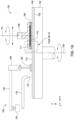
- Figure 1A is a schematic sectional view of a polishing station 100 that may be positioned within a larger chemical mechanical polishing (CMP) system that contains multiple polishing stations 100.
- the polishing station 100 includes a platen 102.
- the platen 102 may rotate about a central axis 104.
- a polishing pad 106 may be placed on the platen 102.
- the polishing pad 106 covers an upper surface of the platen 102 which is at least one to two times larger than the size of the substrate 110 (e.g., substrate diameter) that is to be processed in the polishing station 100.
- the polishing pad 106 and platen 102 are between about 6 inches (150mm) and about 40 inches (1,016mm) in diameter.
- the polishing pad 106 includes a polishing surface 112 configured to contact and process one or more substrates 110 and a supporting surface 103 that is positioned over a surface of the platen 102.
- the platen 102 supports the polishing pad 106 and rotates the polishing pad 106 during polishing.
- a carrier head 108 holds a substrate 110 against the polishing surface 112 of the polishing pad 106.
- the carrier head 108 typically includes a flexible diaphragm 111 that is used to urge the substrate 110 against the polishing pad 106 and a retaining ring 109 that is used to correct for an inherently non-uniform pressure distribution found across the substrate's surface during the polishing process.
- the carrier head 108 may rotate about a central axis 114 and/or move in a sweeping motion to generate relative motions between the substrate 110 and the polishing pad 106.
- a delivery arm 118 delivers a polishing fluid 116, such as an abrasive slurry, is supplied to the polishing surface 112 during polishing.
- the polishing fluid 116 may contain abrasive particles, a pH adjuster and/or chemically active components to enable chemical mechanical polishing of the substrate.
- the slurry chemistry of the polishing fluid 116 is designed to polish wafer surfaces and/or features that may include metals, metal oxides, and semimetal oxides.
- the polishing station 100 also typically includes a pad conditioning assembly 120 that includes a conditioning arm 122 and actuators 124 and 126 that are configured to cause a pad conditioning disk 128 (e.g., diamond impregnated disk) to be urged against and sweep across the polishing surface 112 at different times during the polishing process cycle to abrade and rejuvenate the surface 112 of the polishing pad 106.
- a pad conditioning disk 128 e.g., diamond impregnated disk
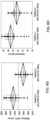
- Figures 1B-1C are schematic sectional views of a portion of the carrier head 108 and a conventional "hard" or high storage modulus E' modulus polishing pad 106A that are positioned in the polishing station 100.
- Figures 1D-1E are schematic sectional views of a portion of the carrier head 108 and a conventional soft or low storage modulus E' polishing pad 106B that are positioned in the polishing station 100.
- Figures 1F-1G are schematic sectional views of a portion of the carrier head 108 and one embodiment of an advanced polishing pad 200, which is described further below, that are positioned in the polishing station 100.
- the flexible diaphragm 111 and upper part of the carrier head 108 have been left out of Figures 1B-1G .
- the flexible diaphragm 111 ( Figure 1A ) is positioned to urge the substrate 110 against the polishing pad 106A, 106B or an advanced polishing pad 200, and a carrier head actuator (not shown) that is coupled to a mounting portion (not shown) of the carrier head 108 is configured to separately urge the carrier head 108 and the retaining ring 109 against the surface of the polishing pad 106A, 106B or advanced polishing pad 200.
- the flexible diaphragm 111 is configured to apply a pressure to the backside of the substrate 110, which is illustrated by the applied force F 2
- the carrier head actuator is configured to apply a force F 1 to the retaining ring 109.
- Figure 1B illustrates a portion of an edge of a substrate 110 that is positioned within the carrier head 108 and over a portion of a conventional "hard” or high storage modulus E' polishing pad 106A before the polishing process is performed on the substrate 110.
- the substrate 110 includes a layer 110A that has one or more device features 110B ( Figure 1H ) that are to be removed and/or planarized during the subsequent CMP process.
- Figure 1C illustrates the substrate 110 during a polishing process using the conventional "hard" polishing pad 106A illustrated in Figure 1B .
- CMP processes that use "hard” polishing pads tend to have non-uniform planarization results due to edge effects found at the edge of substrate 110 that specifically relate to the need to apply a force F 1 to the retaining ring 109 to compensate for a larger inherent polishing non-uniformity found at the edge of the substrate 110 during a CMP process.
- the high storage modulus E', rigid or hard nature of the material used to form the "hard” polishing pad causes a pad rebound or ridge 107A to be formed when the force F 1 is applied by the retaining ring 109 to the "hard” polishing pad 106A.
- the formation of the ridge 107A is generally related to the deformation 107B of the "hard" polishing pad 106A due to the applied force F 1 , which causes the edge of the substrate 110 to polish faster than the center of the substrate 110.
- the higher polishing rate at the edge of the substrate 110 leads to a "global" CMP planarization non-uniformity (e.g., across the substrate non-uniformity).
- Figure 1H is a schematic sectional view of a portion of the substrate 110 that is being polished using the conventional "hard” polishing pad 106A.
- the substrate 110 includes a plurality of features 110B that are formed within the layer 110A, and are removed and/or planarized during the CMP process.
- the high storage modulus E', rigid and/or hard nature of the material used to form the "hard” polishing pad 106A will not allow it to significantly deform on a microscopic scale (e.g., 10 nm-1000 nm feature pitch) when the force F 2 is applied by the flexible diaphragm 111 to the substrate 110.
- the "hard" polishing pad 106A will generally deliver an acceptable amount of planarization and planarization efficiency on a microscopic scale, but achieve poor global planarization results for the reasons discussed above.
- Figure 1D illustrates a portion of an edge of a substrate 110 that is positioned within the carrier head 108 and over a portion of a conventional soft or low storage modulus E' polishing pad 106B before the polishing process is performed on the substrate 110.
- the substrate 110 includes a layer 110A that has one or more device features 110B ( Figure 1I ) that are to be removed and planarized during the subsequent CMP process.
- Figure 1E illustrates the substrate 110 during a polishing process using the conventional soft or low storage modulus E' polishing pad 106B illustrated in Figure 1D .
- Figure 1I is a schematic sectional view of a portion of a substrate that is being polished using the conventional soft or low storage modulus E' polishing pad 106B.
- the flexible or soft or low storage modulus E' nature of the material used to form the soft or low storage modulus E' polishing pad 106B allows the material to deform on a microscopic scale (e.g., 10 nm-1000 nm feature pitch) when the force F 2 is applied by the flexible diaphragm 111 to the substrate 110.
- the material in the soft or low storage modulus E' polishing pad 106B is able to deform and subsequently contact and polish regions of the layer 110A between the device features 110B.
- the act of simultaneously polishing the tops of the features 110B and portions of the regions between the features 110B will create planarization non-uniformities and other planarization problems.
- the soft or low storage modulus E' polishing pad 106B will generally deliver an acceptable amount of global planarization, but achieve a poor planarization efficiency and provide poor dishing results.
- Low storage modulus containing polishing pads provide the benefit on the microscopic scale of improved scratch performance as they allow hard defects, which can be disposed between the pad surface and the surface of the substrate, to be compressed and/or received within the pad matrix rather than forced against the substrate surface by a higher storage modulus material.
- the present invention provides advanced polishing pads 200 that are formed by use of an additive manufacturing process.
- the advanced polishing pads have a pad body that typically includes discrete features or regions that are formed from at least two different material compositions.
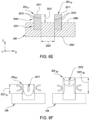
- Figures 1F-1G are schematic sectional views of a portion of the carrier head 108 and a pad body 202 of an advanced polishing pad 200 that are positioned in the polishing station 100.
- it is desirable to form an advanced polishing pad 200 that is configured such that the load applied during the polishing process is distributed through regions of the polishing body 202 that include two or more material compositions to improve the advanced pad's mechanical, structural, and/or dynamic properties.
- the pad body 202 may include a least a first polishing element 204 that is formed from a first storage modulus E' material (e.g., high storage modulus E' material), and a second polishing element 206 that may be formed from a second storage modulus E' material (e.g., medium or low storage modulus E' material).
- a height 150 of the first polishing element(s) 204 from the supporting surface 203 is higher than a height 151 of the second polishing element(s) 206 so that upper surfaces 208 of the first polishing element 204 protrude above the second polishing element(s) 206.
- the force F 2 is delivered by the flexible diaphragm 111 through the first polishing elements 204 to the second polishing element 206 that is supported by a supporting member, such as the platen 102 shown in Figure 1A , so as to form an advanced polishing pad that has desired mechanical and dynamic properties that are a combination of materials in each of the polishing elements.
- a supporting member such as the platen 102 shown in Figure 1A
- the advanced polishing pad offers the benefit of improved global planarity, while maintaining the benefit of improved die and array level planarity offered by a higher storage modulus top pad.
- Figure 1J is a schematic sectional view of a portion of a substrate 110 that is being polished using an advanced polishing pad 200, according to an embodiment of the present disclosure.
- a first polishing element 204 within the polishing body 202 is formed such that it is large enough to span the distance of at least two or more device features 110B (e.g., integrated circuit devices) that are formed on a surface of the substrate 110.
- one or more of the first polishing elements 204 are sized such that they are smaller than the major dimension of the substrate (e.g., radius of a circular substrate), but larger than the smallest device feature size found on a substrate 110.
- a plurality of the first polishing elements 204 each have a lateral dimension 208L, which is parallel to the polishing surface, that is between about 250 micrometers and about 3mm in size.
- the lateral dimension e.g., length 208L
- the lateral dimension can be the diameter or leg of the square, rectangle, or triangle, respectively, of the first polishing element 204.
- the lateral dimension (e.g., width 214) can be the thickness of the toroid or arc when measured along its radius, or even the outer diameter of the toroid in some cases.
- the combination of the first polishing elements 204 and the one or more second polishing elements 206 can thus be used to adjust the advanced polishing pad properties and performance to improve the results of a polishing process performed on a substrate using the advanced polishing pad, as further discussed below.
- the advanced polishing pad 200 may contain at least one high storage modulus E', medium storage modulus E', and/or low storage modulus E' polishing element, and/or chemical structural feature.
- a high storage modulus E' material composition may be at least one, or a mixture of, chemical groups and/or structural features including aromatic ring(s) and some aliphatic chains.
- the high storage modulus E' materials have a crosslinking density greater than 2 %.
- the high storage modulus E' compositions may be the most rigid element in an advanced polishing pad and have a high hardness value, and display the least elongation.
- Medium storage modulus E' compositions may contain a mixture of aromatic rings, crosslinking, but may contain a greater content of aliphatic chains, ether segments, and/or polyurethane segments, than high storage modulus E' compositions.
- the medium storage modulus E' compositions may have intermediate rigidity, hardness, and display a larger amount of elongation than the high storage modulus E' materials.
- Low storage modulus E' compositions may contain aliphatic chains, ether segments, and/or polyurethane segments, with minimal or no contribution from aromatic rings or crosslinking.
- the low storage modulus E' compositions may be flexible, soft, and/or rubber-like.
- the polishing pad body 202 may be formed from at least one viscoelastic materials having different storage moduli E' and/or loss moduli E".
- the pad body may include a first material or a first composition of materials that have a first storage modulus E' and loss modulus E", and a second material or a second composition of materials that have a second storage modulus E' and loss modulus E" that is different than the first storage modulus E' and loss modulus E".
- polishing pad surface features may include a plurality of features with one or more form factors or dimensions, and be a mixture of features that have different mechanical, thermal, interfacial and chemical properties.
- the pad surface features such as channels, grooves and/or proturbances, disposed over, upon, and within the pad body, may include both higher storage modulus E' properties derived from a first material or a first composition of materials and some lower storage modulus E' properties derived from a second material or a second composition of materials that are more elastic than the first material or the first composition of materials.
- advanced polishing pad 200 as used herein is intended to broadly describe an advanced polishing pad that contains one or more of the attributes, materials, features and/or properties that are discussed above and further below. Specific configurations of advanced polishing pads are discussed in conjunction with the examples illustrated in Figures 2A-2K . Unless otherwise specified, the terms first polishing element(s) 204 and the second polishing element(s) 206 are intended to broadly describe portions, regions and/or features within the polishing body of the advanced polishing pad 200. The specific examples of different advanced polishing pad configurations, shown in Figures 2A-2K , are not intended to be limiting as to the scope of the invention, which is defined by the claims, since other similar configurations may be formed by use of the one or more of the additive manufacturing processes described herein.
- the advanced polishing pads are formed by a layer by layer automated sequential deposition of at least one resin precursor composition followed by at least one curing step, wherein each layer may represent at least one polymer composition, and/or regions of different compositions.
- the compositions may include functional polymers, functional oligomers, reactive diluents, and curing agents.
- the functional polymers may include multifunctional acrylate precursor components.
- one or more curing steps may be used, such as exposure of one or more compositions to UV radiation and/or thermal energy. In this fashion, an entire polishing pad may be formed from a plurality of polymeric layers by 3D printing.
- a thickness of the cured layer may be from about 0.1 micron to about 1 mm, such as 5 micron to about 100 microns, and such as 25 microns to about 30 microns.
- Polishing pads according to the present invention may have differing mechanical properties, such as storage modulus E' and loss modulus E", across the pad body 202, as reflected by at least one compositional gradient from polishing element to polishing element.
- Mechanical properties across the polishing pad 200 may be symmetric or non-symmetric, uniform or non-uniform to achieve target polishing pad properties, which may include static mechanical properties, dynamic mechanical properties and wear properties.
- the patterns of either of the polishing elements 204, 206 across the pad body 202 may be radial, concentric, rectangular, spiral, fractal or random according to achieve target properties including storage modulus E' and loss modulus E", across the polishing pad.
- the 3D printing process enables specific placement of material compositions with desired properties in specific pad areas of the pad, or over larger areas of the pad so the properties are combined and represent a greater average of properties or a "composite" of the properties.
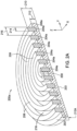
- Figure 2A is a schematic perspective sectional view of an advanced polishing pad 200a according to one embodiment of the present disclosure.
- One or more first polishing elements 204a may formed in alternating concentric rings that are coupled to one or more second polishing elements 206a to form a circular pad body 202.
- a height 210 of the first polishing element(s) 204a from the supporting surface 203 is higher than a height 212 of the second polishing element(s) 206a so that the upper surfaces 208 of the first polishing element(s) 204a protrude above the second polishing element(s) 206a.
- the first polishing element 204 is disposed over a portion 212A of the second polishing element(s) 206a.
- Grooves 218 or channels are formed between the first polishing element(s) 204a, and at least include a portion of the second polishing element(s) 206a.
- the upper surfaces 208 of the first polishing elements 204a form a polishing surface that contacts the substrate, while the grooves 218 retain and channel the polishing fluid.
- the first polishing element(s) 204a are thicker than the second polishing element(s) 206a in a direction normal to a plane parallel to the polishing surface, or upper surface 208, of the pad body 202 (i.e., Z-direction in Figure 2A ) so that the channels or grooves 218 are formed on the top surface of the pad body 202.
- a width 214 of the first polishing elements 204a may be between about 250 microns and about 5 millimeters.
- the pitch 216 between the hard first polishing element(s) 204a may be between about 0.5 millimeters and about 5 millimeters.
- Each first polishing element 204a may have a width within a range between about 250 microns and about 2 millimeters.
- the width 214 and/or the pitch 216 may vary across a radius of the advanced polishing pad 200 to define zones of varied hardness.
- Figure 2B is a schematic partial top view of an advanced polishing pad 200b according to an embodiment of the present disclosure.
- the advanced polishing pad 200b is similar to the advanced polishing pad 200 of Figure 2A except that the advanced polishing pad 200b includes interlocking first polishing elements 204b and second polishing elements 206b.
- the first polishing elements 204b and the second polishing elements 206b form a plurality of concentric rings.
- the first polishing elements 204b may include protruding vertical ridges 220 and the second polishing elements 206b may include vertical recesses 222 for receiving the vertical ridges 220.
- the second polishing elements 206b may include protruding ridges while the first polishing elements 204b include recesses.
- the advanced polishing pad 200b will be mechanically stronger in relation to applied shear forces, which may be generated during the CMP process and/or material handling.
- the first polishing elements and the second polishing elements may be interlocked to improve the strength of the polishing pad and improve physical integrity of the polishing pads.
- the interlocking of the features may be due to physical and/or chemical forces.
- FIG. 2C is a schematic perspective sectional view of an advanced polishing pad 200c according to an embodiment of the present disclosure.
- the polishing pad 200c includes a plurality of first polishing elements 204c extending from a base material layer, such as the second polishing element 206c. Upper surfaces 208 of the first polishing elements 204c form a polishing surface for contacting the substrate during polishing.
- the first polishing elements 204c and the second polishing elements 206c have different material and structural properties.
- the first polishing elements 204c may be formed from a hard material
- the second polishing elements 206c may be formed from an soft or low storage modulus E' material.
- the polishing pad 200c may be formed by 3D printing, similar to the advanced polishing pad 200.
- the first polishing elements 204c may be substantially the same size, or may vary in size to create varied mechanical properties, such as varied storage modulus E' and/or varied loss modulus E", across the polishing pad 200c.
- the first polishing elements 204c may be uniformly distributed across the polishing pad 200c, or may be arranged in a non-uniform pattern to achieve target properties in the advanced polishing pad 200c.
- the first polishing elements 204c are shown to be circular columns extending from the second polishing elements 206c.
- the first polishing elements 204c may be of any suitable cross-sectional shape, for example columns with toroidal, partial toroidal (e.g., arc), oval, square, rectangular, triangular, polygonal, or other irregular section shapes, or combinations thereof.
- the first polishing elements 204c may be of different cross-sectional shapes to tune hardness, mechanical strength or other desirable properties of the advanced polishing pad 200c.
- Figure 2D is a schematic partial side cross-sectional view of a polishing body 202 of an advanced polishing pad 200c according to an embodiment of the present disclosure.
- the advanced polishing pad 200d is similar to the advanced polishing pad 200a, 200b or 200c of Figures 2A-2C except that the advanced polishing pad 200d includes interlocking first polishing elements 204d and second polishing elements 206d.
- the first polishing elements 204d and the second polishing elements 206d may include a plurality of concentric rings and/or discrete elements that form part of the pad body 202, which are, for example, illustrated in Figures 2A , 2B or 2C .
- the first polishing elements 204d may include protruding sidewalls 224 while the second polishing elements 206d may include regions 225 to receive the protruding sidewalls 224 of the first polishing elements 204d.
- the second polishing elements 206d may include protruding sidewalls while the first polishing elements 204d include regions that are configured to receive the protruding sidewalls.
- the boundaries between the first polishing elements 204d and second polishing elements 206d include a cohesive transition from at least one composition of material to another, such as a compositional gradient from a first composition used to form the first polishing element 204d and a second composition used to form the second polishing element 206d.
- the cohesiveness of the materials is a direct result of the additive manufacturing process described herein, which enables micron scale control and intimate mixing of the two or more chemical compositions in a layer by layer additively formed structure.
- Figure 2E is a schematic partial sectional view of a polishing pad according to an embodiment of the present disclosure.
- the advanced polishing pad 200e is similar to the advanced polishing pad 200d of Figure 2D except that the advanced polishing pad 200e includes differently configured interlocking features.
- the advanced polishing pad 200e may include first polishing elements 204e and second polishing elements 206e having a plurality of concentric rings and/or discrete elements.
- the first polishing elements 204e may include horizontal ridges 226 while the second polishing elements 206e may include horizontal recesses 227 to receive the horizontal ridges 226 of the first polishing elements 204e.
- the second polishing elements 206e may include horizontal ridges while the first polishing elements 204e include horizontal recesses.
- vertical interlocking features such as the interlocking features of Figure 2B and horizontal interlocking features, such as the interlocking features of Figures 2D and 2E , may be combined to form an advanced polishing pad.
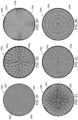
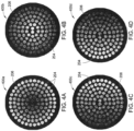
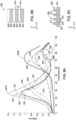
- Figures 2F-2K are schematic plan views of various polishing pad designs according to embodiments of the present disclosure.
- Each of the Figures 2F-2K include pixel charts having white regions (regions in white pixels) that represent the first polishing elements 204f-204k, respectively, for contacting and polishing a substrate, and black regions (regions in black pixels) that represent the second polishing element(s) 206f-206k.
- the white regions generally protrude over the black regions so that channels are formed in the black regions between the white regions.
- the pixels in a pixel chart are arranged in a rectangular pattern, such as an X and Y oriented array, that are used to define the position of the various materials within a layer, or a portion of layer, of an advanced polishing pad.
- the pixels in a pixel chart are arranged in a hexagonal close pack array type of pattern (e.g., one pixel surrounded by six nearest neighbors) that are used to define the position of the various materials within a layer, or a portion of layer of a polishing pad. Polishing slurry may flow through and be retained in the channels during polishing.
- the polishing pads shown in Figures 2F-2K may be formed by depositing a plurality of layers of materials using an additive manufacturing process.
- Each of the plurality of layers may include two or more materials to form the first polishing elements 204f-204k and second polishing element(s) 206f-206k.
- the first polishing elements 204f-204k may be thicker than the second polishing element(s) 206f-206k in a direction normal to a plane that is parallel to the plurality of layers of materials so that grooves and/or channels are formed on a top surface of the polishing pad.
- Figure 2F is a schematic pixel chart of an advanced polishing pad design 200f having a plurality of concentric polishing features 204f.
- the polishing features 204f may be concentric circles of equal width.
- the second polishing element(s) 206f may also have equal width so that the pitch of the first polishing element(s) 204f is constant along the radial direction.
- channels between the first polishing element(s) 204f retain the polishing slurry and prevent rapid loss of the polishing slurry due to a centrifugal force generated by rotation of the polishing pad about its central axis (i.e., center of concentric circles).
- Figure 2G is a schematic pixel chart of a polishing pad design 200g having a plurality of segmented first polishing elements 204g arranged in concentric circles.
- the segmented first polishing elements 204g may have substantially equal length.
- the segmented first polishing elements 204g may form a plurality of concentric circles. In each circle, the segmented first polishing elements 204g may be equally distributed within each concentric circle.
- the segmented first polishing elements 204g may have an equal width in the radial direction.
- the segmented first polishing elements 204g have a substantially equal length irrespective of the radius of the concentric circle (e.g., equal arc length except for the center region of the polishing pad).
- the second polishing element(s) 206g are disposed between the plurality of concentric circles and have an equal width so that the pitch of the concentric circles is constant.
- gaps between the segmented first polishing elements 204g may be staggered from circle to circle to prevent polishing slurry from directly flowing out of the polishing pad under the centrifugal force generated by rotation of the polishing pad about its central axis.
- Figure 2H is a schematic pixel chart of a polishing pad design 200h having spiral first polishing elements 204h disposed over second polishing element(s) 206h.
- the polishing pad 200h has four spiral first polishing elements 204h extending from a center of the polishing pad to an edge of the polishing pad. Even though four spiral polishing features are shown, less or more numbers of spiral first polishing elements 204h may be arranged in similar manner.
- the spiral first polishing elements 204h define spiral channels 218h.
- each of the spiral first polishing elements 204h has a constant width.
- the spiral channels 218h also have a constant width.
- the polishing pad may rotate about a central axis in a direction opposite to the direction of the spiral first polishing elements 204h to retain polishing slurry in the spiral channels.
- the spiral first polishing elements 204h and the spiral channels are formed in a counter-clockwise direction, and thus during polishing the polishing pad may be rotated clockwise to retain polishing slurry in the spiral channels and on the polishing pad.
- each of the spiral channels is continuous from the center of the polishing pad to the edge of the polishing pad. This continuous spiral channels allow polishing slurry along with any polishing waste to flow from the center of the polishing pad to the edge of the polishing pad.
- the polishing pad may be cleaned by rotating the polishing pad in the same direction as the spiral first polishing elements 204h (e.g., counter-clockwise in Figure 2H ).
- Figure 2I is a schematic pixel chart of a polishing pad design 200i having segmented first polishing elements 204i arranged in a spiral pattern on second polishing element(s) 206i.
- the advanced polishing pad illustrated in Figure 2I is similar to the polishing pad in Figure 2H except that the first polishing elements 204i are segmented and the radial pitch of the first polishing elements 204i varies.
- the radial pitch of the segmented first polishing elements 204i decreases from a center of the polishing pad to an edge region of the polishing pad to adjust and/or control the retention of the slurry on different regions of the surface of the polishing pad during processing.
- Figure 2J is a schematic pixel chart of a polishing pad design 200j having a plurality of discrete first polishing elements 204j formed in a second polishing element(s) 206j.
- each of the plurality of first polishing elements 204j may be a cylindrical post type structure, similar to the configuration illustrated in Figure 2C .
- the plurality of first polishing elements 204j may have the same dimension in the plane of the polishing surface.
- the plurality of cylindrical first polishing elements 204j may be arranged in concentric circles.
- the plurality of cylindrical first polishing elements 204j may be arranged in a regular 2D pattern relative to the plane of the polishing surface.
- Figure 2K is a schematic pixel chart of a polishing pad design 200k having a plurality of discrete first polishing elements 204k formed over a second polishing element(s) 206k.
- the polishing pad of Figure 2K is similar to the polishing pad of Figure 2J except that some first polishing elements 204k in Figure 2K may be connected to form one or more closed circles.
- the one or more closed circles may create one or more dams to retain polishing slurry during polishing.
- the first polishing elements 204a-204k in the designs of Figures 2A-2K may be formed from an identical material or identical compositions of materials.
- the material composition and/or material properties of the first polishing elements 204a-204k in the designs of Figure 2A-2K may vary from polishing feature to polishing feature. Individualized material composition and/or material properties allows polishing pads to be tailored for specific needs.
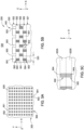
- Figure 3A is a schematic sectional view of an additive manufacturing system 350 that is used to form an advanced polishing pad using an additive manufacturing process according to one or more embodiments of the present invention.
- An additive manufacturing process may include, but are not limited to a process, such as a polyjet deposition process, inkjet printing process, fused deposition modeling process, binder jetting process, powder bed fusion process, selective laser sintering process, stereolithography process, vat photopolymerization digital light processing, sheet lamination process, directed energy deposition process, or other similar 3D deposition process.
- the additive manufacturing system 350 generally includes a precursor delivery section 353, a precursor formulation section 354 and a deposition section 355.
- the deposition section 355 will generally include an additive manufacturing device, or hereafter printing station 300.
- the advanced polishing pad 200 may be printed on a support 302 within the printing station 300.
- the advanced polishing pad 200 is formed layer by layer using one or more droplet ejecting printers 306, such as printer 306A and printer 306B illustrated in Figure 3A , from a CAD (computer-aided design) program.
- the printers 306A, 306B and the support 302 may move relative to each other during the printing process.
- the droplet ejecting printer 306 may include one or more print heads 308 having one or more nozzles (e.g. nozzles 309-312) for dispensing liquid precursors.
- the droplet ejecting printer 306A includes print head 308A that has a nozzle 309 and a print head 308B having a nozzle 310.
- the nozzle 309 may be configured to dispense a first liquid precursor composition to form a first polymer material, such as a soft or low storage modulus E' polymer, while the nozzle 310 may be used to dispense a second liquid precursor to form a second polymer material, such as a hard polymer, or a polymer exhibiting a high storage modulus E'.
- the liquid precursor compositions may be dispensed at selected locations or regions to form an advanced polishing pad that has desirable properties. These selected locations collectively form the target printing pattern that can be stored as a CAD-compatible file that is then read by an electronic controller 305, which controls the delivery of the droplets from the nozzles of the droplet ejecting printer 306.
- the controller 305 is generally used to facilitate the control and automation of the components within the additive manufacturing system 350, including the printing station 300.
- the controller 305 can be, for example, a computer, a programmable logic controller, or an embedded controller.
- the controller 305 typically includes a central processing unit (CPU) (not shown), memory (not shown), and support circuits for inputs and outputs (I/O) (not shown).
- the CPU may be one of any form of computer processors that are used in industrial settings for controlling various system functions, substrate movement, chamber processes, and control support hardware (e.g., sensors, motors, heaters, etc.), and monitor the processes performed in the system.
- the memory is connected to the CPU, and may be one or more of a readily available non-volatile memory, such as random access memory (RAM), flash memory, read only memory (ROM), floppy disk, hard disk, or any other form of digital storage, local or remote.
- Software instructions and data can be coded and stored within the memory for instructing the CPU.
- the support circuits are also connected to the CPU for supporting the processor in a conventional manner.
- the support circuits may include cache, power supplies, clock circuits, input/output circuitry, subsystems, and the like.
- a program (or computer instructions) readable by the controller 305 determines which tasks are performable by the components in the additive manufacturing system 350.
- the program is software readable by the controller 305 that includes code to perform tasks relating to monitoring, execution and control of the delivery and positioning of droplets delivered from the printer 306, and the movement, support, and/or positioning of the components within the printing station 300 along with the various process tasks and various sequences being performed in the controller 305.
- the advanced polishing pad 200 may be solidified by use of a curing device 320 that is disposed within the deposition section 355 of the additive manufacturing system 350.
- the curing process performed by the curing device 320 may be performed by heating the printed polishing pad to a curing temperature or exposing the pad to one or more forms of electromagnetic radiation or electron beam curing.
- the curing process may be performed by exposing the printed polishing pad to radiation 321 generated by an electromagnetic radiation source, such as a visible light source, an ultraviolet light source, and x-ray source, or other type of electromagnetic wave source that is disposed within the curing device 320.
- the additive manufacturing process offers a convenient and highly controllable process for producing advanced polishing pads with discrete features formed from different materials and/or different compositions of materials.
- soft or low storage modulus E' features and/or hard or high storage modulus E' features may be formed using the additive manufacturing process.
- the soft or low storage modulus E' features of a polishing pad may be formed from the first composition containing polyurethane segments dispensed from the nozzle 312 of the printer 306B, and hard or high storage modulus E' features of the polishing pad may be formed from droplets of the second composition dispensed from the nozzle 310 of the printer 306A.
- first polishing elements 204 and/or the second polishing element(s) 206 may each be formed from a mixture of two or more compositions.
- a first composition may be dispensed in the form of droplets by a first print head, such as the print head 308A
- the second composition may be dispensed in the form of droplets by a second print head, such as the print head 308B of the printer 306A.
- first polishing elements 204 with a mixture of the droplets delivered from multiple print heads requires/includes the alignment of the pixels corresponding to the first polishing elements 204 on predetermined pixels within a deposition map found in the controller 305.
- the print head 308A may then align with the pixels corresponding to where the first polishing elements 204 are to be formed and then dispense droplets on the predetermined pixels.
- the advanced polishing pad may thus be formed from a first composition of materials that is formed by depositing droplets of a first droplet composition and a second material that comprises a second composition of materials that is formed by depositing droplets of a second droplet composition.
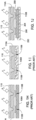
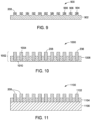
- Figure 3B is a schematic cross-sectional view of a portion of the printing station 300 and advanced polishing pad 200 during the pad manufacturing process.
- the printing station 300 includes two printers 306A and 306B that are used to sequentially form a portion of the advanced polishing pad 200.
- the portion of the advanced polishing pad 200 shown in Figure 3B may, for example, include part of either the first polishing element 204 or the second polishing elements 206 in the finally formed advanced polishing pad 200.
- the printers 306A and 306B are configured to deliver droplets "A" or "B,” respectively, to a first surface of the support 302 and then successively to a surface of the growing polishing pad that is disposed on the support 302 in a layer by layer process.
- a second layer 348 is deposited over a first layer 346 which has been formed on the support 302.
- the second layer 348 is formed over the first layer 346 which has been processed by the curing device 320 that is disposed downstream from the printers 306A and 306B in the pad manufacturing process.
- portions of the second layer 348 may be simultaneously processed by the curing device 320 while one or more of the printers 306A and 306B are depositing droplets "A" and/or "B" onto the surface 346A of the previously formed layer 346.
- the layer that is currently being formed may include a processed portion 348A and an unprocessed portion 348B that are disposed on either side of a curing zone 349A.
- the unprocessed portion 348B generally includes a pattern, such as an array, of dispensed droplets, such as dispensed droplets 343 and 347, which are deposited on the surface 346A of the previously formed layer 346 by use of the printers 306B and 306A, respectively.
- Figure 3C is a close up cross-sectional view of a dispensed droplet 343 that is disposed on a surface 346A of the previously formed layer 346. Based on the properties of the materials within the dispensed droplet 343, and due to surface energy of the surface 346A the dispensed droplet will spread across the surface an amount that is larger than the size of the original dispensed droplet (e.g., droplets "A" or "B"), due to surface tension. The amount of spread of the dispensed droplet will vary as a function of time from the instant that it is deposited on the surface 346A.
- the spread of the droplet will reach an equilibrium size, and have an equilibrium contact angle ⁇ .
- the spread of the dispensed droplet across the surface affects the resolution of the placement of the droplets on the surface of the growing polishing pad, and thus the resolution of the features and material compositions found within various regions of the final polishing pad.
- each droplet at a desired size before the droplet has a chance to spread to its uncured equilibrium size on the surface of the substrate.
- the energy supplied to the dispensed droplet, and surface that it is placed on, by the curing device 320 and the droplet's material composition are adjusted to control the resolution of each of the dispensed droplets. Therefore, one important parameter to control or tune during a 3D printing process is the control of the dispensed droplet's surface tension relative to the surface that it is disposed on.
- the curing enhancement components will generally include materials that are able to adjust: 1) the amount of bulk curing that occurs in the material in the dispensed droplet during the initial exposure to a desired amount of electromagnetic radiation, 2) the amount of surface curing that occurs in the material in the dispensed droplet during the initial exposure to a desired amount of electromagnetic radiation, and 3) the amount of surface property modification (e.g., additives) to the surface cured region of the dispensed droplet.
- the amount of surface property modification to the surface cured region of the dispensed droplet generally includes the adjustment of the surface energy of the cured or partially cured polymer found at the surface of the dispensed and at least partially cured droplet.
- each dispensed droplet it is desirable to partially cure to "fix" its surface properties and dimensional size during the printing process.
- the ability to "fix" the droplet at a desirable size can be accomplished by adding a desired amount of at least one curing enhancement components to the droplet's material composition and delivering a sufficient amount of electromagnetic energy from the curing device 320 during the additive manufacturing process.
- mJ/cm 2 milli-joule per centimeter squared
- UV ultraviolet
- the UV radiation may be provided by any UV source, such as mercury microwave arc lamps (e.g., H bulb, H+ bulb, D bulb, Q bulb, and V bulb type lamps), pulsed xenon flash lamps, high-efficiency UV light emitting diode arrays, and UV lasers.
- the UV radiation may have a wavelength between about 170 nm and about 500 nm.
- the size of dispensed droplets "A", “B” may be from about 10 to about 200 microns, such as about 50 to about 70 microns.
- the uncured droplet may spread on and across the surface to a size 343A of between about 10 and about 500 microns, such as between about 50 and about 200 microns.
- the height of such a droplet may be from about 5 to about 100 microns, depending on such factors as surface energy, wetting, and/or resin precursor composition which may include other additives, such as flow agents, thickening agents, and surfactants.
- One source for the additives is BYK-Gardner GmbH of Geretsried, Germany.
- the actual time it takes to partially cure the dispensed droplet, due to the exposure to delivered curing energy may be longer or shorter than the time that the droplet resides on the surface before it is exposed to the delivered radiation, since the curing time of the dispensed droplet will depend on the amount of radiant energy and wavelength of the energy provide from the curing source 320.
- an exposure time used to partially cure a 120 micrometer ( ⁇ m) dispensed droplet is about 0.4 microseconds ( ⁇ s) for a radiant exposure level of about 10-15 mJ/cm 2 of UV radiation.
- ⁇ m micrometer
- ⁇ s microseconds
- a radiant exposure level of about 10-15 mJ/cm 2 of UV radiation In an effort to "fix" the droplet in this short timeframe one must position the dispense nozzle of the droplet ejecting printer 306 a short distance from the surface of the surface of the polishing pad, such as between 0.1 and 10 millimeters (mm), or even 0.5 and 1 mm, while the surface 346A of the advanced polishing pad are exposed to the radiation 321 delivered from the curing device 320.
- the contact angle ⁇ of the droplet can be controlled to control the fixed droplet size, and thus the resolution of the printing process.
- the underlying layer cure may be a cure of about 70 % acrylate conversion.
- a droplet that has been fixed, or at least partially cured, is also referred to herein as a cured droplet.
- the fixed droplet size 343A is between about 10 and about 200 microns.
- the contact angle also referred to herein as the dynamic contact angle (e.g., non-equilibrium contact angle) for a "fixed" droplet can be desirably controlled to a value of at least 50°, such as greater than 55°, or even greater than 60°, or even greater than 70°.
- the resolution of the pixels within a pixel chart that is used to form a layer, or a portion of a layer, by an additive manufacturing process can be defined by the average "fixed" size of a dispensed droplet.
- the material composition of a layer, or portion of a layer can thus be defined by a "dispensed droplet composition", which a percentage of the total number of pixels within the layer, or portion of the layer, that include droplets of a certain droplet composition.
- a region of a layer of a formed advanced polishing pad is defined as having a dispensed droplet composition of a first dispensed droplet composition of 60%, then 60% percent of the pixels within the region will include a fixed droplet that includes the first material composition.
- the material composition ratio is a ratio of the number of pixels that have a first material composition disposed thereon to the number of pixels that have a second material composition disposed thereon. In one example, if a region was defined as containing 1,000 pixels, which are disposed across an area of a surface, and 600 of the pixels contain a fixed droplet of a first droplet composition and 400 of the pixels contain a fixed droplet of a second droplet composition then the material composition ratio would include a 3:2 ratio of the first droplet composition to the second droplet composition.
- each pixel may contain greater than one fixed droplet (e.g., 1.2 droplets per pixel) then the material composition ratio would be defined by the ratio of the number of fixed droplets of a first material to the number of fixed droplets of a second material that are found within a defined region. In one example, if a region was defined as containing 1,000 pixels, and there were 800 fixed droplet of a first droplet composition and 400 fixed droplets of a second droplet composition within the region, then the material composition ratio would be 2:1 for this region of the advanced polishing pad.
- the amount of curing of the surface of the dispensed droplet that forms the next underlying layer is an important polishing pad formation process parameter, since the amount of curing in this "initial dose" affects the surface energy that the subsequent layer of dispensed droplets will be exposed to during the additive manufacturing process.
- the amount of the initial cure dose is also important since it will also affect the amount of curing that each deposited layer will finally achieve in the formed polishing pad, due to repetitive exposure of each deposited layer to additional transmitted curing radiation supplied through the subsequently deposited layers as they are grown thereon.
- to effect polymerization of a 10-30 micron thick layer of dispensed droplets may be performed by dispensing each droplet on a surface and then exposing the dispensed droplet to UV radiation at a radiant exposure level of between about 10 and about 15 mJ/cm 2 after a period of time of between about 0.1 seconds and about 1 second has elapsed.
- the radiation level delivered during the initial cure dose may be varied layer by layer. For example, due to differing dispensed droplet compositions in different layers, the amount of UV radiation exposure in each initial dose may be adjusted to provide a desirable level of cure in the currently exposed layer, and also to one or more of the underlying layers.
- the droplet composition and the amount of energy delivered from the curing device 320 during the initial curing step which is a step in which the deposited layer of dispensed droplets are directly exposed to the energy provided by the curing device 320, to cause the layer to only partially cure a desired amount.
- the initial curing process it is desirable for the initial curing process to predominantly surface cure the dispensed droplet versus bulk cure the dispensed droplet, since controlling the surface energy of the formed layer is important for controlling the dispensed droplet size.
- the amount that a dispensed droplet is partially cured can be defined by the amount of chemical conversion of the materials in the dispensed droplet.
- the amount that a layer is initially cured may be equal to or greater than about 70% of the dispensed droplet.
- the process of partially curing a dispensed droplet during the initial layer formation step can also be important to assure that there will be some chemical bonding/adhesion between subsequently deposited layers, due to the presence of residual unbonded groups, such as residual acrylic groups. Since the residual unbonded groups have not been polymerized, they can be involved in forming chemical bonds with a subsequently deposited layer.
- the formation of chemical bonds between layers can thus increase the mechanical strength of the formed advanced polishing pad in the direction of the layer by layer growth during the pad formation process (e.g., Z-direction in Figure 3B ). As noted above, the bonding between layers may thus be formed by both physical and/or chemical forces.
- a mixture of dispensed droplets includes a 50:50 ratio of the dispensed droplets 343 and 347 (or a material composition ratio of 1:1), wherein the dispensed droplet 343 includes at least one different material from the material found in the dispensed droplet 347.
- Properties of portions of the polishing body 202 may be adjusted or tuned according to the ratio and/or distribution of a first composition and a second composition that are formed from the positioning of the dispensed droplets during the deposition process.
- the weight % of the first composition may be from about 1 % by weight based on total composition weight to about 100 % based on total composition weight.
- the second composition may be from about 1 % by weight based on total composition weight to about 100 % based on total composition weight.
- compositions of two or more materials can be mixed in different ratios to achieve a desired effect.
- the composition of the first polishing elements 204 and/or second polishing elements 206 is controlled by selecting at least one composition or a mixture of compositions, and size, location, and/or density of the droplets dispensed by one or more printers. Therefore, the controller 305 is generally adapted to position the nozzles 309-310, 311-312 to form a layer that has interdigitated droplets that have been positioned in a desired density and pattern on the surface of the polishing pad that is being formed. In some configurations, dispensed droplets may be deposited in such a way as to ensure that each drop is placed in a location where it does not blend with other drops, and thus each remains a discrete material "island" prior to being cured.
- the dispensed droplets may also be placed on top of prior dispensed droplets within the same layer to increase the build rate or blend material properties. Placement of droplets relative to each other on a surface may also be adjusted to allow partial mixing behavior of each of the dispensed droplets in the layer. In some cases, it may be desirable to place the droplets closer together or farther apart to provide more or less mixing of the components in the neighboring droplets, respectively. It has been found that controlling droplet placement relative to other dispensed droplets and the composition of each droplet can have an effect on the mechanical and polishing properties of the formed advanced polishing pad.
- compositions of the first polishing elements 204 and/or second polishing elements 206 encompass forming features on a polishing pad with a plurality of materials that are interconnected via compositional gradients.
- the composition of the first polishing elements 204 and/or second polishing elements 206 in a polishing pad are adjusted within a plane parallel to the polishing surface and/or through the thickness of the polishing pad, as discussed further below.
- compositional gradients and the ability to tune the chemical content locally, within, and across an advanced polishing pad are enabled by "ink jettable” low viscosity compositions, or low viscosity "inks” in the 3D printing arts that are used to form the droplets "A” and/or "B” illustrated in Figure 3B .
- the low viscosity inks are "pre-polymer” compositions and are the “precursors” to the formed first polishing elements 204 and second polishing elements 206 found in the pad body 202.
- the low viscosity inks enable the delivery of a wide variety of chemistries and discrete compositions that are not available by conventional techniques (e.g., molding and casting), and thus enable controlled compositional transitions or gradients to be formed within different regions of the pad body 202.
- This is achieved by the addition and mixing of viscosity thinning reactive diluents to high viscosity functional oligomers to achieve the appropriate viscosity formulation, followed by copolymerization of the diluent(s) with the higher viscosity functional oligomers when exposed to a curing energy delivered by the curing device 320.
- the reactive diluents may also serve as a solvent, thus eliminating the use of inert nonreactive solvents or thinners that must be removed at each step.
- a first precursor 356 is mixed with a second precursor 357 and a diluent 358 to form a first printable ink composition 359, which is delivered to reservoir 304B of the printer 306B, and used to form portions of the polishing body 202.
- a third precursor 366 can be mixed with a fourth precursor 367 and a diluent 368 to form a second new printable ink composition 369, which is delivered to reservoir 304A of the printer 306A, and used to form another portion of the polishing body 202.
- the first precursor 356 and the third precursor 366 each comprise an oligomer, such as multifunctional oligomer
- the second precursor 357 and the fourth precursor 367 each comprise a multifunctional monomer
- diluent 358 and the diluent 368 each comprise a reactive diluent (e.g., monomer) and/or initiator (e.g., photoinitiator).
- first printable ink composition 359 may include a first precursor 356 which includes a reactive difunctional oligomer, comprising aliphatic chain segments, which may have a viscosity from about 1000 centipoise (cP) at 25 °C, to about 12,000 cP at 25 °C, is then mixed with and thus diluted by a 10 cP at 25 °C reactive diluent (e.g., diluent 358), such as monoacrylate, to create a new composition that has new viscosity.
- a reactive difunctional oligomer comprising aliphatic chain segments, which may have a viscosity from about 1000 centipoise (cP) at 25 °C, to about 12,000 cP at 25 °C, is then mixed with and thus diluted by a 10 cP at 25 °C reactive diluent (e.g., diluent 358), such as monoacrylate, to create a new composition that has new vis
- the printable composition thus obtained may exhibit a viscosity from about 80 cP to about 110 cP at 25 °C, and a viscosity from about 15 cP to about 30 cP at 70 °C, which may be effectively dispensed from a 3D printer ink jet nozzle.
- Figures 4A-4F provide examples of an advanced polishing pads that include a compositional gradient across one or more regions of the polishing body.
- the white pixel marks are intended to schematically illustrate where a dispensed droplet of a first material is dispensed while the black pixel marks illustrate where no material is dispensed within one or more layers used to form the polishing pad.
- compositional gradients in the cured material, or material formed by a plurality of cured droplets can be formed in the printed layers used to form at least part of a complete polishing pad.
- the tailored composition of the printed layers within a polishing pad can be used to adjust and tailor the overall mechanical properties of the polishing pad.
- composition of polishing features may vary in any suitable pattern. Although polishing pads described herein are shown to be formed from two kinds of materials, this configuration is not intended to be limiting of the scope of the invention, which is defined by the claims, since polishing pads including three or more kinds of materials is within the scope of the present disclosure. It should be noted that the compositions of the polishing features in any designs of the polishing pad, such as the polishing pads in Figures 2A-2K , may be varied in similar manner as the polishing pads in Figures 4A-4F .
- Figures 4A and 4B are black and white bitmap images reflecting pixel charts of a printed layer within an advanced polishing pad that includes portions of first polishing elements 204 and second polishing element(s) 206.
- the white pixel marks are where a droplet of a first material is dispensed while the black pixel marks are where no material is dispensed and cured.
- Figure 4A is the pixel chart 400a of a first portion of a layer within an advanced polishing pad 200 and
- Figure 4B is the pixel chart 400b of a second portion of the same advanced polishing pad.
- the first portion may be dispensed by a first print head according to the pixel chart 400a and the second portion may be dispensed by a second print head according to the pixel chart 400b.
- the two print heads superimpose the pixel charts 400a, 400b together to form one or more layers that contain discrete polishing features.
- the polishing features near an edge region of the polishing pad include more of the first material than the second material.
- the polishing features near a center region of the polishing pad include more of the second material than the first material.
- each polishing feature has a unique combination of the first material and the second material.
- the first polishing elements 204 include a first combination of the first material and the second material and the second polishing elements 206 include a different second combination of the first material and the second material. Therefore, by use of pixel charts, the polishing body can be sequentially formed so that a desired gradient in material composition is achieved in different parts of the polishing body to achieve a desired polishing performance of the advanced polishing pad.
- Figures 4C and 4D are schematic pixel charts 400c, 400d of a polishing pad having features.
- Figure 4C is the pixel chart 400c of a first portion of a polishing pad and
- Figure 4D is the pixel chart 400d of a second portion of the same polishing pad.
- the polishing pad according to Figures 4C, 4D is similar to the polishing pad of Figures 4A, 4B except the gradient in the material composition of the polishing body varies from left to right across the polishing pad.
- Figure 4E is a schematic view of a web based polishing pad 400e that is formed using an additive manufacturing process to form a polishing surface 208 that has a gradient in material composition across the polishing surface 208 (e.g., Y-direction).
- the polishing material may be disposed over a platen 102 between a first roll 481 and a second roll 482.
- One example may involve a substrate having an initial surface texture removed rapidly using a planarizing portion of the polishing pad 400e that has a high elastic modulus and then moving the substrate to a second portion of the polishing pad 400e that has a lower elastic modulus to buff the substrate surface and reduce scratch defects.
- Figure 4F is schematic side cross-sectional view of an advanced polishing pad 400f that is formed using an additive manufacturing process to form a polishing base layer 491 that has a gradient in material composition in the Z-direction. Gradients in the material composition and/or material properties of the stacked printed layers of the polishing base layer 491 can vary from a high concentration to a low concentration of a first material to a second material in one direction, or vice versa. In some cases, one or more regions within the polishing pad may include more complex concentration gradients, such as a high/low/high or low/high/low concentration gradient of at least two materials that have differing material properties.
- the advanced polishing pad 400f may include a polishing element region 494 that may include discrete regions that include at least a first polishing element 204 and a second polishing element 206.
- the polishing element region 494 may include a portion of a polishing body 202 that contains one or more of the structures shown in Figures 2A-2K .
- the base layer 491 includes a homogeneous mixture of two or more different materials in each layer formed within the base layer 491.
- the homogeneous mixture may include a mixture of the materials used to form the first polishing element 204 and the second polishing element 206 in each layer formed within the base layer 491.
- the phrase homogeneous mixture is intended to generally describe a material that has been formed by dispensing and curing printed droplets that have at least two different compositions within each layer, and thus may contain a mixture of small regions of the at least two different compositions that are each sized at a desired resolution.
- the interface between the polishing base layer 491 and the polishing element region 494 may include a homogeneous blend of the materials found at the upper surface of the polishing base layer 491 and the lower surface of the polishing element region 494, or include a discrete transition where the differing material composition in the first deposited layer of the polishing element region 494 is directly deposited on the surface of the polishing base layer 491.
- polishing element region 494 it is desirable to form a gradient in the material composition in the first polishing elements 204 and/or second polishing elements 206 in a direction normal to the polishing surface of the polishing pad.
- Surface features use low storage modulus E' can be used for defect removal and scratch reduction, and high storage modulus E' features can be used to enhance die and array scale planarization.
- a first layer may have a material composition ratio of the first printed composition to the second printed composition of 1:1, a material composition ratio of the first printed composition to the second printed composition of 2:1 in a second layer and a material composition ratio of the first printed composition to the second printed composition of 3:1 in a third layer.
- the first printed composition has a higher storage modulus E' containing material than the second printed composition, and the direction of sequential growth of the first, second and third layers is away from a supporting surface of the advanced polishing pad.
- a gradient can also be formed within different parts of a single layer by adjusting the placement of the printed droplets within the plane of the deposited layer.
- the construction of an advanced polishing pad 200 begins by creating a CAD model of the polishing pad design. This can be done through the use of existing CAD design software, such as Unigraphics or other similar software. An output file, which is generated by the modelling software, is then loaded to an analysis program to ensure that the advanced polishing pad design meets the design requirements (e.g., water tight, mass density). The output file is then rendered, and the 3D model is then "sliced" into a series of 2D data bitmaps, or pixel charts. As noted above, the 2D bitmaps, or pixel charts, are used to define the locations across an X and Y plane where the layers in the advanced polishing pad will be built. In some additive manufacturing process applications these locations will define where a laser will pulse, and in other applications the location where a nozzle will eject a droplet of a material.
- the coordinates found in the pixel charts are used to define the location at which a specific droplet of uncured polymer will be placed using, for example, a poly jet print head. Every coordinate for an X and Y location and a given pad supporting Z stage position will be defined based on the pixel charts. Each X, Y and Z location will include either a droplet dispense or droplet non-dispense condition.
- Print heads may be assembled in an array in the X and/or Y directions to increase build rate or to deposit additional types of materials. In the examples shown in Figures 4A-4D , the black pixels indicate locations where nozzles will not deposit materials and the white pixels indicate where nozzles will deposit materials.
- An additive manufacturing device such as a 3D printer can be used to form an advanced polishing pad by depositing thermoplastic polymers, depositing and curing of a photosensitive resin precursor compositions, and/or laser pulse type sintering and fusing of a dispensed powder layer.
- the advanced polishing pad formation process may include a method of polyjet printing of UV sensitive materials.
- droplets of a precursor formulation e.g., first printable ink composition 359
- resin precursor composition is deposited onto the build stage.
- the material may be leveled with the use of a roller or other means to smooth drops into a flat film layer or transfer away excess material.
- a UV lamp or LED radiation source passes over the deposited layer to cure or partially cure the dispensed droplets into a solid polymer network.
- a monochromatic light source e.g., LED light source
- has a narrow emitted wavelength range and/or a narrow spot size that is specifically tailored to substantially or partially cure one or more dispensed droplets, and thus not adversely affect other surrounding regions or prior formed layers of the formed advanced polishing pad.
- the monochromatic light source is configured to deliver wavelengths of light within a range between 100nm and 500nm, such as between about 170 nm and 400 nm.
- a UV LED source is configured to deliver UV light within a band of +/-10 nm at a central wavelength of 240 nm, 254 nm, 365 nm, 385 nm, 395 nm or 405 nm wavelengths. This process is built layer on top of layer with adequate cohesion within the layer and between layers to ensure the final embodiment of the pad model is mechanically sound.
- heat may be added during the formation of one or more of the layers.
- the delivery of heat allows the polymer network formed in each cured or partially cured layer to relax and thereby reduce stress and remove stress history in the film. Stress in the film can result in unwanted deformation of the polishing pad during or after the polishing pad formation process. Heating the partially formed polishing pad while it is on the printer's build tray ensures that the final pad properties are set through the layer by layer process and a predictable pad composition and polishing result can be achieved.
- the area surrounding the growing polishing pad may be modified to reduce the oxygen exposure to the uncured resin.
- the advanced polishing pad 200 includes pores that are formed within the unitary pad body 202 in a desirable distribution or pattern so that the properties of a formed layer within, for example, the first or the second polishing elements or overall pad structure will have desirable thermal and/or mechanical properties.
- the properties of one or more regions of the advanced polishing pad can be controlled.
- porosity in at least the surface of the formed pad will help to increase pad surface interaction with slurry and slurry nanoparticle (e.g., ceria oxide and silicon dioxide) loading on the pad, which can enhance the polishing removal rate and reduce the common wafer-to-wafer removal rate deviations typically found in CMP processes.
- slurry and slurry nanoparticle e.g., ceria oxide and silicon dioxide
- Figure 5A illustrates a schematic plan view of a pixel chart that is used to form a region 500 of a layer 522 ( Figure 5B ) of a first or a second polishing element of a polishing pad that contains pore-forming regions according to one or more implementations of the present disclosure.
- the pixel chart includes a rectangular pattern of pore-forming regions 502 that are formed by dispensing one or more droplets of a porosity-forming agent 504 ( Figure 5B ) from a first print head onto a surface and then at least partially surrounding the pore-forming regions 502 with one or more structural material containing regions 501 that include a material that is formed by dispensing droplets of one or more resin precursor compositions from at least a second print head.
- the porosity-forming agent 504 can then later be removed in a post processing step or during a polishing process to form pores in one or more layers of the polishing pad.
- the porosity-forming agent material is removed from a formed advanced polishing pad 200 when the polishing pad is used in a CMP polishing process.
- the porosity-forming agent material may be removed due to the interaction of the porosity-forming agent disposed at a surface 520 of the first or second polishing elements in the advanced polishing pad with one or more components found within a slurry that is disposed between the first and/or second polishing elements and a substrate that is being polished.
- the pore-forming regions 502 are surrounded by a structural material containing region 501 that is formed by dispensing droplets of a resin-precursor formulation across a surface on which the layer 522 is formed.
- compositional gradients in the cured structural material found within the structural material containing region 501 and/or gradients in the size and density of the pore-forming regions 502 can be used to form at least part of a complete polishing pad that has desirable mechanical and thermal properties.
- composition of the pore-forming material disposed within the pore-forming regions 502 and distribution and size of the pore-forming regions 502 across of the polishing pad 200 (i.e., X-Y plane) or through the thickness of the polishing element (i.e., Z direction) may vary in any suitable pattern.
- polishing pads described herein are shown to be formed from two kinds of materials, this configuration is not intended to be limiting of the scope of the invention, which is defined by the appended claims, since polishing pads including three or more kinds of materials is within the scope of the present disclosure.
- compositions of the structural material found within a polishing pad may be varied in a similar manner as discussed above in conjunction with Figures 4A-4F .
- the material found within a formed structural material containing region 501 may include a mixture of two or more different materials that varies in one or more directions across (e.g., X and/or Y direction) or through (e.g., Z direction) the formed layer.
- Figure 5B is a side cross-sectional view of a portion of the region 500 illustrated in Figure 5A according to one or more aspects of the present disclosure.
- the portion shown in Figure 5B includes a plurality of layers 522 that are formed on an optional base layer 521 by use of an additive manufacturing process as described herein.
- the layers are shown in Figure 5B as being disposed between two dashed lines, however, due to the processes described herein at least the structural material containing region 501 parts of adjacent layers may be formed such that there is no distinct physical division between layers in a formed polishing pad 200.
- the layers 522 each include pore-forming regions 502 that are interspersed between regions of the structural material containing region 501.
- the porosity-forming agent 504 may be easily removed leaving an unfilled void within the pore-forming regions 502, and thus forming a pore 503.
- the pixel charts used to form each layer 522 includes pattern that includes an array of porosity-forming agent 504 containing pore-forming regions 502 that are formed in a desired pattern across the surface of the formed layer.
- the pattern of porosity-forming agent 504 containing pore-forming regions 502 can be formed in a rectangular array that has a desirable pitch in both the X and Y directions.
- the pattern of porosity-forming agent 504 containing pore-forming regions 502 may be formed in any desirable pattern including a hexagonal array of pore-forming regions 502, a directionally varying pattern of pore-forming regions 502, a random pattern of pore-forming regions 502 or other useful pattern of pore-forming regions 502.
- the pixel charts used to form adjacent layers 522 are shifted a desired distance 525 in one or more directions (e.g., X, Y or X and Y directions) relative to each other, or formed in differing relative X-Y patterns, so that the pore-forming regions 502 are not placed on top of each other in adjacently positioned layers as the polishing pad is formed.
- similarly configured patterns of pore-forming regions 502 in adjacent layers may be staggered a desired distance in one or more directions relative to each other so that the pore-forming regions 502 are not placed on top of each other in the adjacently positioned layers.
- Figure 5C illustrates is a side cross-sectional view of a portion of the region 500 illustrated in Figure 5A according to another aspect of the present disclosure.
- two or more of the deposited layers may be aligned with each other so that the layers are formed directly on top of each other.
- two layers 522A and 522B are formed so that the 522A layer is directly on top of the layer 522B so that the pore-forming regions 502 are placed one on top of the other.
- the next or subsequent layers may then be shifted a desired distance 525 relative to the layers 522A-B, so that the pore-forming regions 502 in the subsequent layers are not placed on top of the layers 522A-B.
- This configuration in which two or more layers, within a larger stack of layers, are formed directly on top of each other may be useful in cases where the fixed droplet size resolution in the X and Y directions may be greater than the thickness of the layer in the Z direction.
- the fixed droplet size in the X and Y directions is twice as large as the thickness in the Z direction, thus allowing a regular pattern of printed material to be formed in the X, Y and Z directions when two layers are placed on top of each other.
- the pixel charts used to form the pore-forming regions 502 and the surrounding structural material containing region 501 within a layer can be used to create portions of the polishing features that have a consistent or varying porosity in one or more directions X, Y, or Z.
- the polishing features near an edge region of the advanced polishing pad may include more of the resin precursor formulation used to form the structural material within the structural material containing region 501 than the porosity-forming agent 504 containing pore-forming regions 502.
- the polishing features near a center region of the polishing pad may also include a higher percentage of pore-forming regions 502 per layer (e.g., higher density) than the polishing features near the edge region.
- each polishing feature of the same type e.g., first polishing elements 204
- first and second polishing elements 204, 206 has a unique combination of the resin precursor formulation, the porosity-forming agent and the density of the pore-forming regions 502 per layer and/or per polishing element.
- the first polishing elements 204 include a first combination of the resin precursor formulation and the porosity-forming agent
- the second polishing elements 206 include a different second combination of the resin precursor formulation and the porosity-forming agent. Therefore, by use of pixel charts, the polishing body can be sequentially formed so that a desired porosity gradient is achieved in different parts of the polishing body to achieve a desired polishing performance of the advanced polishing pad.
- a method of forming a layer of a porous advanced polishing pad according to the invention is defined by the claims. Among others it comprises the following steps: First, one or more droplets of a resin composition, such as described herein, are dispensed in a desired X and Y pattern to form the structural material portion of a formed layer. In one implementation, the one or more droplets of a resin composition are dispensed on a support if the one or more droplets constitute a first layer. In some implementations, the one or more droplets of a resin composition are dispensed on a previously deposited layer (e.g., second layer, etc.).
- one or more droplets of a porosity forming composition containing a porosity-forming agent 504 are dispensed in a desired X and Y pattern to form the pore-forming regions 502 within the formed layer.
- the one or more droplets of the porosity forming composition are dispensed on a support if the one or more droplets constitute a first layer.
- the one or more droplets of the porosity forming composition are dispensed on a previously deposited layer.
- the dispensing processes of the first and second operations are typically performed separately in time and at different X-Y coordinates.
- the dispensed one or more droplets of the curable resin precursor and the dispensed one or more droplets of the porosity forming composition are at least partially cured.
- the dispensed one or more droplets of the curable resin precursor and the dispensed one or more droplets of the porosity forming composition are exposed to at least one of an annealing process, a rinsing process, or both to remove the porosity-forming agent.
- the rinsing process may include rinsing with water, another solvent such as alcohol (e.g., isopropanol) or both.
- the annealing process may include heating the deposited pad structure to a low temperature (e.g., about 100 degrees Celsius) under a low pressure to vaporize the porosity-forming agent.
- a low temperature e.g., about 100 degrees Celsius
- an optional second curing process is performed on the formed layer or final pad to form the final porous pad structure.
- the first, second, third and fifth processing steps may also be sequentially repeated in any desired order to form a number of stacked layers before the fourth step is completed.
- the porosity-forming agent 504 may include materials that have hydrophilic and/or have hydro-degradable behaviors, such as hydrogels, poly(lactic-co-glycolic acid) (PLGA), and Polyethylene glycol (PEG), which degrade in the presence of an aqueous solutions.
- hydrogels poly(lactic-co-glycolic acid) (PLGA)
- PLGA poly(lactic-co-glycolic acid)
- PEG Polyethylene glycol
- the porosity-forming agent 504 disposed within a formed polishing pad is configured to degrade, such as dissolve into an aqueous slurry (e.g., porosity-forming agent is soluble in the slurry) or break down in the presence of slurry, and leave a pore (e.g., 100 nm - 1 ⁇ m opening or void) in the exposed surface of the advanced polishing pad.
- the porosity-forming agent 504 may include an oligomeric and/or polymeric material that is mixed with an inert soluble component.
- the inert soluble components may include ethylene glycol, polyethylene glycol, propylene glycol, diethylene glycol, dipropylene glycol, triethylene glycol, tetraethylene glycol and glycerol.
- the inert soluble components may also include corresponding mono alkyl or dialky ethers and alkyl groups that may include methyl, ethyl, propyl, isopropyl, butyl or isobutyl groups.
- the porosity-forming agent 504 includes PEG and about 5% to 15% of an oligomeric and/or polymeric material, such as an acrylate material.
- a hydrogel material may be used that is based on polyethylene glycol acrylates or methacrylates.
- hydrogel materials can be made from polar materials that are not soluble in most resin precursor formulations.
- the hydrogel materials can be made into pore-forming materials by cross-linking with diacrylates and dimethacrylates in a ratio of about 1 to 10%. The hydrogel materials are formed in this way will still have solubility in water and can be washed away with water to generate pores.
- the structural material containing region 501 may include a material that is formed from one or more of the resin precursor components disclosed herein.
- the structural material containing region 501 may include a material that is formed by use of a resin precursor component that is selected from, but not restricted to, at least one of the materials listed in Table 3 or families of materials in which the materials listed in Table 3 are from.
- Other useful resin precursor components that may be used alone or in combination with one or more of the resin precursor components disclosed herein may also include the thiol-ene and thiol-yne type, epoxy, Michael addition type, ring-opening polymerization (ROP), and ring forming or Diels-Alder polymerization (DAP) type components described herein.
- the pores formed with a pad body 202 may be formed by causing the porosity-forming agent 504 change phase, such as vaporize, during a subsequent advanced polishing pad formation process.
- the porosity within the formed pad may be generated by delivering electromagnetic radiation to a portion of the polishing pad to induce the generation change in phase of the porosity-forming agent material.
- an advanced polishing pad pre-polymer composition may contain compounds, polymers, or oligomers that are thermally labile and that may contain of thermally labile groups. These porogen and thermally labile groups may be cyclic groups, such as unsaturated cyclic organic groups.
- the porogen may comprise a cyclic hydrocarbon compound.
- porogens include, but are not restricted to: norbornadiene (BCHD, bicycle(2.2.1)hepta-2,5-diene), alpha-terpinene (ATP), vinylcyclohexane (VCH), phenylacetate, butadiene, isoprene, and cyclohexadiene.
- BCHD norbornadiene
- ATP alpha-terpinene
- VCH vinylcyclohexane
- phenylacetate butadiene
- isoprene and cyclohexadiene.
- a pre-polymer layer is deposited that contains a radiation curable oligomer with a covalently bound porogen group. After exposure to UV radiation and heat, a porous polymer layer may be formed by the effusion of the porogen group.
- an advanced polishing pad pre-polymer composition may contain compounds, polymers, or oligomers that are mixed with a water containing compound.
- a plurality of porous layers may be formed by sequential layer deposition and then driving out the water containing compound to form a pore.
- pores may be generated by thermally induced decomposition of compounds that form a gas by-product, such as azo compounds, which decompose to form nitrogen gas.
- the resin precursor composition may include polymer spheres, such as 100 nm - 1 ⁇ m of diameter sized polymer nanospheres or micro-spheres that are disposed within the droplets that are used to form the advanced polishing pad.
- the polymer sphere is between 100 nm and 20 ⁇ m in size, such as between 100 nm and 5 ⁇ m in size.
- the polymer spheres are configured to degrade, such as dissolve into the aqueous slurry or break down in the presence of slurry, and leave a pore (e.g., 100 nm - 1 ⁇ m pore feature) in the exposed surface of the advanced polishing pad.
- the polymer spheres may comprise one or more solid polymer materials that have desirable mechanical properties, thermal properties, wear properties, degradation properties, or other useful property for use within the formed advanced polishing pad.
- the polymer spheres may comprise a solid polymer shell that encloses a liquid (e.g., water) or gas material so that the polymer sphere will provide desirable mechanical, thermal, wear, or other useful property to the formed advanced polishing pad.
- the polymer spheres may also be used to form pores within regions of a fixed droplet that is used to form one or more regions within portions of a formed polishing element (e.g., polishing elements 204 and/or 206) to provide desirable mechanical, thermal, wear, or other useful property to these portions of a formed advanced polishing pad.
- the polymer spheres may include materials that have hydrophilic and/or have hydro-degradable behaviors, such as hydrogels and poly(lactic-co-glycolic acid), PLGA, which degrade in the presence of an aqueous solutions.
- the polymer spheres are typically uniformly dispersed in the droplet formulations and in the cured materials after performing the additive manufacturing process (e.g., 3D printing).
- hydrogel particles may be used that are based on polyethylene glycol acrylates or methacrylates. These types of particles are made from polar materials and are not soluble in most formulations.
- the hydrogel particles can be made into particle form by cross-linking with diacrylates and dimethacrylates in a ratio of about 1 to 15%. The hydrogel particles formed in this way will still have solubility in water and can be washed away with water to generate pores.
- the materials used to form portions of the pad body 202 may each be formed from at least one ink jettable pre-polymer composition that may be a mixture of functional polymers, functional oligomers, reactive diluents, and curing agents to achieve the desired properties of an advanced polishing pad.
- the pre-polymer inks or compositions may be processed after being deposited by use of any number of means including exposure or contact with radiation or thermal energy, with or without a curing agent or chemical initiator.
- the deposited material can be exposed to electromagnetic radiation, which may include ultraviolet radiation (UV), gamma radiation, X-ray radiation, visible radiation, IR radiation, and microwave radiation and also accelerated electrons and ion beams may be used to initiate polymerization reactions.
- electromagnetic radiation may include ultraviolet radiation (UV), gamma radiation, X-ray radiation, visible radiation, IR radiation, and microwave radiation and also accelerated electrons and ion beams may be used to initiate polymerization reactions.
- electromagnetic radiation may include ultraviolet radiation (UV), gamma radiation, X-ray radiation, visible radiation, IR radiation, and microwave radiation and also accelerated electrons and ion beams may be used to initiate polymerization reactions.
- electromagnetic radiation may include ultraviolet radiation (UV), gamma radiation, X-ray radiation, visible radiation, IR radiation, and microwave radiation and also accelerated electrons and ion beams may be used to initiate polymerization reactions.
- additives to aid the polymerization such as sensitizers, initiators, and/or curing agents
- two or more polishing elements within a unitary pad body 202, may be formed from the sequential deposition and post deposition processing of at least one radiation curable resin precursor composition, wherein the compositions contain functional polymers, functional oligomers, monomers, and/or reactive diluents that have unsaturated chemical moieties or groups, including but not restricted to: vinyl groups, acrylic groups, methacrylic groups, allyl groups, and acetylene groups.
- the unsaturated groups may undergo free radical polymerization when exposed to radiation, such as UV radiation, in the presence of a curing agent, such as a free radical generating photoinitiator, such as an Irgacure ® product manufactured by BASF of Ludwigshafen, Germany.
- a curing agent such as a free radical generating photoinitiator, such as an Irgacure ® product manufactured by BASF of Ludwigshafen, Germany.
- the first type of photoinitiator which is also referred to herein as a bulk cure photoinitiator, is an initiator which cleaves upon exposure to UV radiation, yielding a free radical immediately, which may initiate a polymerization.
- the first type of photoinitiator can be useful for both surface and through or bulk cure of the dispensed droplets.
- the first type of photoinitiator may be selected from the group including, but not restricted to: benzoin ethers, benzyl ketals, acetyl phenones, alkyl phenones, and phosphine oxides.
- the second type of photoinitiator which is also referred to herein as a surface cure photoinitiator, is a photoinitiator that is activated by UV radiation and forms free radicals by hydrogen abstraction from a second compound, which becomes the actual initiating free radical.
- This second compound is often called a co-initiator or polymerization synergist, and may be an amine synergist. Amine synergists are used to diminish oxygen inhibition, and therefore, the second type of photoinitiator may be useful for fast surface cure.
- the second type of photoinitiator may be selected from the group including but not restricted to benzophenone compounds and thioxanthone compounds.
- An amine synergist may be an amine with an active hydrogen
- an amine synergist such as an amine containing acrylate may be combined with a benzophenone photoinitiator in a resin precursor composition formulation to: a) limit oxygen inhibition, b) fast cure a droplet or layer surface so as to fix the dimensions of the droplet or layer surface, and c), increase layer stability through the curing process.
- a curing atmosphere or environment that is oxygen limited or free of oxygen, such as an inert gas atmosphere, and chemical reagents that are dry, degassed and mostly free of oxygen.
- controlling the amount of the chemical initiator in the printed formulation is an important factor in controlling the properties of a formed advanced polishing pad, since the repeated exposure of underlying layers to the curing energy as the advanced polishing pad is formed will affect the properties of these underlying layers.
- the repeated exposure of the deposited layers to some amount of the curing energy e.g., UV light, heat, etc.
- the surface cure kinetics are not faster than through-cure (bulk-cure), as the surface will cure first and block additional UV light from reaching the material below the surface cured region; thus causing the overall partially cured structure to be "under-cured.”
- the resin precursor composition includes a polymeric photoinitiator and/or an oligomer photoinitiator that has a moderate to high molecular weight that is selected so that it is relatively immobile within bulk region of a dispensed droplet prior to, during and/or after performing a curing process on the droplet.
- the moderate to high molecular weight type of photoinitiator is typically selected such that it will not, or at least minimally, migrate within a partially cured droplet.
- the polymeric and oligomeric photoinitiators will tend to be immobilized within the bulk region of cured material and not migrate to or vaporize from the surface or interfacial region of the cured material, due to the photoinitiator's relatively high molecular weight.
- the moderate to high molecular weight type of photoinitiator is relative immobile within the formed droplet, the curing, composition and mechanical properties of the bulk region and the curing, composition, mechanical properties and surface properties (e.g., hydrophilicity) of the surface of the dispensed droplet will remain relatively uniform and stable.
- the moderate to high molecular weight type of photoinitiator may be a material that has a molecular weight that is greater than 600, such as greater than 1000.
- the moderate to high molecular weight type of photoinitiator may be a material that is selected from the group of PL Industries PL-150 and IGM Resins Omnipol 1001, 2702, 2712, 682, 910, 9210, 9220, BP, and TX.
- the immobile feature of the polymeric and oligomeric photoinitiators, in comparison to small molecular photoinitiators, will also enhance the health, safety, and environmental impact of the additive manufacturing process used to form an advanced polishing pad.
- a moderate to high molecular weight type of photoinitiator is selected for use in a droplet formulation such that it will not significantly alter the viscosity of the final formulation used to form the droplet that is dispensed on the surface of the growing polishing pad.
- lower molecular weight photoinitiator undesirably alter the viscosity of the formulation used to form the droplet. Therefore, by selecting a desirable moderate to high molecular weight type of photoinitiator the viscosity of the final droplet formulation can be adjusted or maintained at a level that can be easily dispensed by the deposition hardware, such as a print head, during an additive manufacturing process (e.g., 3D printing process).
- Some of the desirable formulations have a very low viscosity (10-12 cP at 70°C). However, in some cases the printing hardware, such as the Connex500 printing tool, the viscosity has to be 13-17 cP at 70°C.
- oligomeric content in the formulation has to be increased. Increasing the oligomeric content will have an impact on the mechanical properties of the formed layers. Thus, if one adds a polymeric photoinitiator, it will increase viscosity automatically and will have smaller impact on the mechanical properties on the formed layer.
- the photoinitiator is styrene based, which is available from Synasia, IGM Resins, and PL Industries.
- PI chemical structure
- the first and second polishing elements 204 and 206 may contain at least one oligomeric and/or polymeric segments, compounds, or materials selected from: polyamides, polycarbonates, polyesters, polyether ketones, polyethers, polyoxymethylenes, polyether sulfone, polyetherimides, polyimides, polyolefins, polysiloxanes, polysulfones, polyphenylenes, polyphenylene sulfides, polyurethanes, polystyrene, polyacrylonitriles, polyacrylates, polymethylmethacrylates, polyurethane acrylates, polyester acrylates, polyether acrylates, epoxy acrylates, polycarbonates, polyesters, melamines, polysulfones, polyvinyl materials, acrylonitrile butadiene styrene (ABS), copolymers derived from styrene, copolymers derived from butadiene, halogenated polymers, block copo
- ABS
- compositions used to form the first polishing element 204 and second polishing element 206 may be achieved using at least one UV radiation curable functional and reactive oligomer with at least one of the aforementioned polymeric and/or molecular segments, such as that shown in chemical structure (A):
- the difunctional oligomer as represented in chemical structure A contains segments that may contribute to the low, medium, and high storage modulus E' character of materials found in the first polishing element 204 and second polishing element 206 in the pad body 202.
- the aromatic groups may impart added stiffness to pad body 202 because of some local rigidity imparted by the phenyl rings.
- a rubber-like reactive oligomer, polybutadiene diacrylate may be used to create a softer and more elastic composition with some rubber-like elastic elongation as shown in chemical structure (B):
- Polybutadiene diacrylate includes pendant allylic functionality (shown), which may undergo a crosslinking reaction with other unreacted sites of unsaturation.
- the residual double bonds in the polybutadiene segment "m" are reacted to create crosslinks which may lead to reversible elastomeric properties.
- an advanced polishing pad containing compositional crosslinks may have a percent elongation from about 5 % to about 40 %, and a E'30:E'90 ratio of about 6 to about 15.
- crosslinking chemistries include sulfur vulcanization and peroxide, such as tert-butyl perbenzoate, dicumyl peroxide, benzoyl peroxide, di-tert-butyl peroxide and the like.
- sulfur vulcanization and peroxide such as tert-butyl perbenzoate, dicumyl peroxide, benzoyl peroxide, di-tert-butyl peroxide and the like.
- 3 % benzoyl peroxide by total formulation weight, is reacted with polybutadiene diacrylate to form crosslinks such that the crosslink density is at least about 2 %.
- Chemical structure (C) represents another type of reactive oligomer, a polyurethane acrylate, a material that may impart flexibility and elongation to the advanced polishing pad.
- An acrylate that contains urethane groups may be an aliphatic or an aromatic polyurethane acrylate, and the R or R' groups shown in the structure may be aliphatic, aromatic, oligomeric, and may contain heteroatoms such as oxygen.
- Reactive oligomers may contain at least one reactive site, such as an acrylic site, and may be monofunctional, difunctional, trifunctional, tetrafunctional, pentafunctional and/or hexafunctional and therefore serve as foci for crosslinking.
- Figure 7B is a plot of stress vs. strain for some cured reactive oligomers that may be useful for creating 3D printable ink compositions.
- the oligomers may represent "soft" or a low storage modulus E' materials, “medium soft” or medium storage modulus E' materials, or “hard” or high storage modulus E' materials (e.g., Table 1).
- the storage modulus E' (e.g., slope, or ⁇ yl ⁇ x) increases from a soft and flexible and stretchable polyurethane acrylate to an acrylic acrylate, then to a polyester acrylate, and then to the hardest in the series, a hard and high storage modulus E" epoxy acrylate.
- Figure 7B illustrates how one may choose a storage modulus E' material, or a range or mixture of storage modulus E' materials, that may be useful for production of an advanced polishing pad.
- Functional oligomers may be obtained from a variety of sources including Sartomer USA of Exton, PA, Dymax Corporation of Torrington, CT, USA, and Allnex Corporation of Alpharetta, GA, USA.
- multifunctional acrylates including di, tri, tetra, and higher functionality acrylates, may be used to create crosslinks within the material used to form, and/or between the materials found in, the first polishing element 204 and second polishing element 206, and thus adjust polishing pad properties including storage modulus E', viscous dampening, rebound, compression, elasticity, elongation, and the glass transition temperature. It has been found that by controlling the degree of crosslinking within the various materials used to form the first polishing element 204 and second polishing element 206 desirable pad properties can be formed.
- multifunctional acrylates may be advantageously used in lieu of rigid aromatics in a polishing pad formulation, because the low viscosity family of materials provides a greater variety of molecular architectures, such as linear, branched, and/or cyclic, as well as a broader range of molecular weights, which in turn widens the formulation and process window.
- Some examples of multifunctional acrylates are shown in chemical structures (D) (1,3,5-triacryloylhexahydro-1 ,3,5-triazine), and (E) (trimethylolpropane triacrylate):
- crosslinking agent may undergo a Michael addition type reaction with acrylic moiety to form a covalent crosslink, or an amine group may react with an epoxide group to create a covalent crosslink.
- the crosslinks may be formed by ionic or hydrogen bonding.
- the crosslinking agent may contain linear, branched, or cyclic molecular segments, and may further contain oligomeric and/or polymeric segments, and may contain heteroatoms such as nitrogen and oxygen.
- Crosslinking chemical compounds that may be useful for polishing pad compositions are available from a variety of sources including: Sigma-Aldrich of St. Louis, MO, USA, Sartomer USA of Exton, PA, Dymax Corporation of Torrington, CT, USA, and Allnex Corporation of Alpharetta, GA, USA.
- reactive diluents can be used as viscosity thinning solvents that are mixed with high viscosity functional oligomers to achieve the appropriate viscosity formulation, followed by copolymerization of the diluent(s) with the higher viscosity functional oligomers when exposed to a curing energy.
- the viscosity of bisphenol-A ethoxylate diacrylate may be about 1350 centipoise (cP) at 25 °C, a viscosity which may be too high to effect dispense of a such a material in a 3D printing process.
- bisphenol-A ethoxylate diacrylate with a lower viscosity reactive diluents, such as low molecular weight acrylates, to lower the viscosity to about 1 cP to about 100 cP at 25 °C, such as about 1 cP to about 20 cP at 25 °C.
- the amount of reactive diluent used depends on the viscosity of the formulation components and the diluent(s) themselves. For example, a reactive oligomer of 1000 cP may require at least 40 % dilution by weight of formulation to achieve a target viscosity.
- Examples of reactive diluents are shown in chemical structures (F) (isobornyl acrylate), (G) (decyl acrylate), and (H) (glycidyl methacrylate):
- the respective viscosities of F-G at 25 °C are 9.5 cP, 2.5 cP, and 2.7 cP, respectively.
- Reactive diluents may also be multifunctional, and therefore may undergo crosslinking reactions or other chemical reactions that create polymer networks.
- glycidyl methacrylate (H) serves as a reactive diluent, and is mixed with a difunctional aliphatic urethane acrylates, so that the viscosity of the mixture is about 15 cP.
- the approximate dilution factor may be from about 2:1 to about 10:1, such as about 5:1.
- An amine acrylate may be added to this mixture, such as dimethylaminoethyl methacrylate, so that it is about 10 % by weight of the formulation. Heating the mixture from about 25 °C to about 75 °C causes the reaction of the amine with the epoxide, and formation of the adduct of the acrylated amine and the acrylated epoxide.
- a suitable free radical photoinitiator such as Irgacure ® 651
- the mixture may be dispensed by a suitable 3D printer so that a 20 micron thick layer is formed on a substrate.
- the layer may then be cured by exposing the droplet or layer for between about 0.1 ⁇ s to about 10 seconds, such as about 0.5 seconds, to UV light from about 200 nm to about 400 nm using a scanning UV diode laser at an intensity of about 10 to about 50 mJ/cm 2 to create a thin polymer film.
- Reactive diluent chemical compounds that may be useful for 3D printed polishing pad compositions are available from a variety of sources including Sigma-Aldrich of St. Louis, MO, USA, Sartomer USA of Exton, PA, Dymax Corporation of Torrington, CT, USA, and Allnex Corporation of Alpharetta, GA, USA.
- Epoxy group containing materials may be cationically curable, wherein the ring opening polymerization (ROP) of epoxy groups may be initiated by cations such as protons and Lewis acids.
- the epoxy materials may be monomers, oligomers or polymers, and may have aliphatic, aromatic, cycloaliphatic, arylaliphatic or heterocyclic structures; and they can also include epoxide groups as side groups or groups that form part of an alicyclic or heterocyclic ring system.
- UV-initiated cationic photopolymerization exhibits several advantages compared to the free-radical photopolymerization including lower shrinkage, better clarity, better through cure via living polymerization, and the lack of oxygen inhibition.
- UV cationic polymerization involves an acid catalyst which causes the ring opening of a cyclic group, such as an epoxide group.
- a cyclic group such as an epoxide group.
- CROP cationic ring opening polymerization
- the technique may polymerize important classes of monomers which cannot be polymerized by free radical means, such as epoxides, vinyl ethers, propenyl ethers, siloxanes, oxetanes, cyclic acetals and formals, cyclic sulfides, lactones and lactams.
- These cationically polymerizable monomers include both unsaturated monomers, such as glycidyl methacrylate (chemical structure H) that may also undergo free-radical polymerization through the carbon-carbon double bonds as described herein.
- Photoinitiators that generate a photoacid when irradiated with UV light ( ⁇ 225 to 300 nm) or electron beams include, but are not limited to aryl onium salts, such as iodonium and sulfonium salts, such as triarylsulfonium hexafluorophosphate salts, which may be obtained from BASF of Ludwigshafen, Germany (Irgacure ® product).
- the material(s) used to form the first polishing element 204 and the second polishing element 206, and thus the unitary pad body 202 may be formed from the sequential deposition and cationic cure of at least one radiation curable resin precursor composition, wherein the compositions contain functional polymers, functional oligomers, monomers, and/or reactive diluents that have epoxy groups.
- Mixed free radical and cationic cure systems may be used to save cost and balance physical properties.
- the first polishing element 204 and the second polishing element 206 may be formed from the sequential deposition and cationic and free radical cure of at least one radiation curable resin precursor composition, wherein the compositions contain functional polymers, functional oligomers, monomers, reactive diluents that have acrylic groups and epoxy groups.
- an observation window or CMP end-point detection window may be formed from a composition cured by the cationic method.
- some of the layers in the formed advanced polishing pad may be formed by use of a cationic curing method and some of the layers may be formed from a free radical curing method.
- addition type polymerization reactions and compounds may be useful for preparing printed polishing articles, such as CMP pads, that have a pad body 202, a first polishing element 204 and a second polishing element 206.
- CMP pads printed polishing articles
- a condensation polymerization reaction may produce at least one by-product, such as water or other compounds, and thus is not a desirable synthetic pathway to form a printed polishing article.
- Useful and alternative addition type polymerizations, in addition to the aforementioned acrylic free radical and cationic epoxy polymerizations include, but are not restricted to, thiol-ene and thiol-yne type, epoxy reactions with amines and/or alcohols, Michael addition type, ring-opening polymerization (ROP), and ring forming or Diels-Alder polymerization (DAP) type.
- addition type polymerization reactions may involve the reaction of at least one compound with another compound and/or the use of electromagnetic radiation to form a polymeric material with desirable properties, but without the generation of by-product(s).
- a compound that undergoes an addition polymerization reaction with another compound may be also be described herein as an “addition polymer precursor component,” and may also be referred to as “part A” and/or “part B” in a synthetic material formation process involving at least one addition polymer precursor component.
- addition polymerizations such as thiol-ene and ROP types, may enable the tuning and manipulation of physical properties that are important in the production of printed polymer layers and polishing articles, including, but not restricted to: storage modulus (E'), loss modulus (E"), viscous dampening, rebound, compression, elasticity, elongation, and the glass transition temperature.
- E' storage modulus
- E loss modulus
- viscous dampening rebound
- compression compression
- elasticity elongation
- glass transition temperature glass transition temperature
- the alternate addition polymers may contain segments that may contribute to the low, medium, and high storage modulus E' character of materials found in the first polishing element 204 and second polishing element 206 in the pad body 202.
- aromatic groups may impart added stiffness to the pad body 202 because of some local rigidity imparted by the phenyl rings. It is also believed that increasing the length of alkyl and/or ether chain segments of the alternate addition polymers described herein will lower the storage modulus E' and thus produce a softer material with increased flexibility.
- the alternate addition polymers may also contain R groups that may be aliphatic, aromatic, oligomeric, and may contain heteroatoms such as oxygen.
- the alternate addition polymers may also have R groups that are monofunctional, difunctional, trifunctional, tetrafunctional, pentafunctional and/or hexafunctional, and therefore serve as foci for crosslinking, the manipulation of which may produce "soft” or a low storage modulus E' materials, “medium soft” or medium storage modulus E' materials, or “hard” or high storage modulus E' materials.
- addition polymers and R groups may have water soluble groups that may contain negative and/or positive charges, or may be neutrally charged, including, but not restricted to: amides, imidazoles, ethylene and propylene glycol derivatives, carboxylates, sulfonates, sulfates, phosphates, hydroxyl and quaternary ammonium compounds.
- Some water soluble compounds that may be polymerized include, but are not restricted to: 1-vinyl-2-pyrrolidone, vinylimidazole, polyethylene glycol diacrylate, acrylic acid, sodium styrenesulfonate, Hitenol BC10 ® , Maxemul 6106 ® , hydroxyethyl acrylate and [2-(methacryloyloxy)ethyltrimethylammonium chloride, 3-allyloxy-2-hydroxy-1-propanesulfonic acid sodium, sodium 4-vinylbenzenesulfonate, [2-(methacryloyloxy)ethyl]dimethyl-(3-sulfopropyl)ammonium hydroxide, 2-acrylamido-2-methyl-1-propanesulfonic acid, vinylphosphonic acid, allyltriphenylphosphonium chloride, (vinylbenzyl)trimethylammonium chloride, allyltriphenylphosphonium chloride, (vinylbenzyl
- the addition polymers may include one or more linear polymers.
- these types of polymers may include, but are not limited to poly(methyl methacrylate), poly(styrene-co-methyl methacrylate), poly(styrene-co-methacrylic acid), poly(styrene-co-acrylonitrile), poly(methyl methacrylate-co-ethyl acrylate) and poly(benzyl methacrylate).
- a thiol-ene type addition reaction may be used to produce printed polymer layers and polishing articles such as CMP pads.
- Thiol-ene/thiol-yne reactions involve the addition of an S-H bond across a double or triple bond by either a free radical or ionic mechanism.
- Thiol-ene reactions may be thought of as the sulfur version of the hydrosilylation reaction, and may also be used produce sulfur centered radical species that undergo polymerization reactions with compounds containing unsaturated carbon-carbon bonds.
- thiol-ene addition polymerizations include: no oxygen inhibition, polymerization efficiency approaching 100%, reaction with allylic groups (in addition to acrylic), and a high degree macromolecular structural control which in turn provides the ability to tune the storage or loss modulus and tan delta properties of the formed polishing article, in contrast to conventional acrylic free radical polymerization formed polishing article materials. Additionally, mixed polymerizations involving a mixture of at least one compound with acrylic and allylic groups, may be performed to broaden a material's tan delta and to adjust its mechanical properties, such as flexibility, elongation, and hardness, and to save cost and balance physical properties, such as storage modulus.
- an aliphatic allyl ether may be mixed in a 25:75 mole ratio to an acrylic ester, prior to deposition, in a single reservoir.
- the acrylic compounds may be used to increase modulus and crosslinking after curing, and to achieve a lower cost/mole of monomer(s), in certain regions of a polishing article.
- Figure 3D is a schematic view of a nozzle assembly that can be used to mix and dispense one or more of the resin precursor components that may contain the addition polymer precursors or compounds, such as a part A and a part B for a thiol-ene polymerization, according to an embodiment of this disclosure.
- the droplet ejecting printer 306A may contain a nozzle 314, and a reservoir 315 and a reservoir 316 that each deliver at least one resin precursor component to a mixing region 318.
- the resin precursor components delivered to the mixing region 318 are mixed at the point of use by turbulence inducing elements 318a to form one or more droplets 319 that contains a mixture of the mixed resin precursor composition.
- the turbulence inducing elements 318a may also include a spiral tortuous path through which the resin precursor components are mixed. In another embodiment the mixture may be premixed and contained in a single reservoir. After mixing, the droplets 319 are delivered to a surface of a substrate, such as a polishing article, as illustrated in Figures 3A-3B and 3D . After dispense of the mixed resin precursor components, the droplets are cured. It is noted that the containment, mixing and dispense schemes illustrated in Figure 3D may be suitable for any of the following chemistries described herein, as for example, such as a thiol-ene polymerization used for the printing of a polishing article.
- Thiol-ene addition polymerization reactions typically require UV irradiation to cure the dispensed droplet, such as UV radiation with a wavelength from between about 150 nm to about 350 nm, such as 254 nm, and with or without a photoinitiator, such as Irgacure TPO-L ® , benzophenone or dimethoxyphenyl acetophenone.
- UV radiation with a wavelength from between about 150 nm to about 350 nm, such as 254 nm
- a photoinitiator such as Irgacure TPO-L ®
- benzophenone or dimethoxyphenyl acetophenone such as benzophenone or dimethoxyphenyl acetophenone.
- thiols examples include: (I.) 1,3-propanedithiol, (J.) 2,2'-(ethylenedioxy)diethanethiol, and (K.) trimethylolpropane tris(3-mercaptopropionate).
- Examples of unsaturated compounds that may be useful in producing printed polymer layers by use of a thiol-ene chemistry include: (L.) 1,4-butanediol divinyl ether, (M.) 1,4-cyclohexanedimethanol divinyl ether, and (N.) 1,3,5-triallyl-1,3,5-triazine-2,4,6(1H,3H,5H)-trione.
- Reactions of amines and alcohols (nucleophiles) with electron deficient carbon centers, such as those found in epoxide groups, is another type of an addition polymerization (e.g., thermoset) that may be useful for the production of printed polymer layers and polishing articles such as CMP pads.
- an addition polymerization e.g., thermoset
- the control of crosslinking and the nature of the interchain bonds give cured epoxies many desirable characteristics. These characteristics include excellent adhesion to many substrates, high strength (tensile, compressive and flexural), chemical resistance, fatigue resistance, and corrosion resistance.
- properties of the uncured epoxy resins such as viscosity, which are important in processing, as well as final properties of cured epoxies such as strength or chemical resistance, can be optimized by appropriate selection of the epoxy monomer and the curing agent or catalyst.
- the chemical structures of both amine and alcohol curing agents and epoxides may be varied to obtain the desired physical property such as storage modulus (E'), hardness, adhesion, flexibility and elongation.
- E' storage modulus
- one may also choose different degrees of functionality to achieve a desired crosslink density, and thus tune the physical properties of the formed material, such as the storage modulus (E').
- an amine-epoxy type addition polymerization reaction may be used to produce printed polymer layers and polishing articles by co-mixing a part A (e.g. diamine hardener) with a part B (e.g. diepoxide). This may be achieved as previously described and shown in Figure 3D .
- a part A e.g. diamine hardener
- a part B e.g. diepoxide
- one or more amine-epoxy addition polymer layers may then be formed by rapidly curing the dispensed droplets to a solid state using a heat source, such as a flash xenon lamp or an IR laser.
- thermal curing accelerants may also be used for curing epoxy thermoset polymer layers to form a printed polishing article, and include, but are not restricted to: phenyl ureas, boron trichloride amine complexes, imidazoles, aliphatic bis ureas, phenols, and resorcinol.
- a one-pack thermoset formulation may be used to produce printed polymer layers and CMP pads, which are dispensed from a single reservoir.
- At least one diepoxide or multifunctional epoxide may be contained in a single reservoir at a certain temperature, such as 25 °C, with a thermal latent initiator such as dicyanodiamide (DICY), with or without an accelerant, such as 4,4' methylene bis (phenyl dimethyl urea).
- a thermal latent initiator such as dicyanodiamide (DICY)
- an accelerant such as 4,4' methylene bis (phenyl dimethyl urea
- Such a mixture may be stable for some period of time, such as hours (depending on the reactivity of the components), until heat is applied.
- heat can be applied by use of a flash xenon lamp or an IR laser, which causes the activation of the DICY compound and cure to a solid state.
- the epoxy compounds or resins may include bisphenol-F diglycidyl ether, bisphenol-A diglycidyl ether, epoxidized phenol novolac resins, epoxidized cresol novolac resins, epoxidized rubbers, epoxidized oils, epoxidized urethanes, epoxy ethers, polycyclic aliphatic epoxies, polycyclic aromatic epoxies, and combinations thereof.
- the epoxies may be monomeric, oligomeric, or polymeric.
- an epoxy modified polyurethane or rubber may be mixed with a low viscosity aromatic epoxide, resorcinol diglycidyl ether, to achieve a desired modulus upon amine curing at a temperature from about 25 °C to about 200 °C, such as 75 °C.
- epoxides that may be useful in producing printed polymer layers are: (O.) resorcinol diglycidyl ether, (P.) polypropylene glycol) diglycidyl ether, and (Q.) 4,4'-methylenebis(N,N-diglycidylaniline).
- amine compounds are available for the production of printed polymer layers and CMP pads.
- the amines may be monomeric, oligomeric, and polymeric in form, and contain at least one amine group per molecule, with at least one amine active hydrogen.
- Suitable amines include, but not restricted to: aliphatic amines, cycloaliphatic amines, polyetheramines, polyethylenimine, dendritic amines, and aromatic amines.
- Some examples of amines that may be useful in producing printed polymer layers are: (R.) 1,3-cyclohexanediamine, (S.) m-xylylenediamine, and (T.) Jeffamine D ® .
- epoxy and amine chemical compounds that may undergo epoxy addition polymerization reactions serve as non-limiting illustrative examples, and do not restrict the invention, which is defined by the claims.
- Chemical compounds that may undergo epoxy addition polymerization reactions may be obtained from suppliers such as BASF of Ludwigshafen, Germany, Sigma-Aldrich of St. Louis, MO, USA, CVC Thermoset Specialties of Emerald Performance Materials, Moorestown, NJ, USA, and Huntsman Advanced Materials, The Woodlands, Texas, USA.
- Multifunctional amines such as diamines, are useful in other addition polymerization reactions.
- One such reaction is known as a Michael addition reaction (a 1,4-conjugate addition), in which a primary or secondary amine reacts with an electron deficient double bond.
- the Michael addition is a reaction between nucleophiles and activated olefin and alkyne functionalities, wherein the nucleophile adds across a carbon-carbon multiple bond that is adjacent to an electron withdrawing and resonance stabilizing activating group, such as a carbonyl group.
- Michael addition nucleophile is known as the "Michael donor”
- the activated electrophilic olefin is known as the “Michael acceptor”
- reaction product of the two components is known as the “Michael adduct”.
- Michael donors include, but are not restricted to: amines, thiols, phosphines, carbanions, and alkoxides.
- Michael acceptors include, but are not restricted to: acrylate esters, alkyl methacrylates, acrylonitrile, acrylamides, maleimides, cyanoacrylates and vinyl sulfones, vinyl ketones, nitro ethylenes, a,b-unsaturated aldehydes, vinyl phosphonates, acrylonitrile, vinyl pyridines, azo compounds, beta-keto acetylenes and acetylene esters. It is further noted that any number of different Michael acceptors and/or mixtures may be used to obtain or tune a desired physical property, such as flexibility, elongation, hardness, toughness, modulus, and the hydrophobic or hydrophilic nature of the article.
- the Michael acceptor may be mono, di, tri, and tetra functional, and each group R may have different molecular weights, chain lengths, and molecular structures.
- the Michael donor may be chosen or identified based on the aforementioned characteristics.
- a printed polishing article may be produced using a diacrylate, 1,4-butanediol diacrylate (10.1 mmol), and a diamine, piperazine (10 mmol), as illustrated by reaction example 1.
- the diacrylate and diamine may reside in two separate reservoirs 315, 316, and then may be mixed within the mixing region 318 of a tortuous path dispense nozzle 314, and dispensed as droplets, and then thermally cured with a Xenon flash lamp to form a polymer layer.
- acrylates that can be used to produce a Michael addition polymer
- amines that contain at least two primary or secondary amine groups may include, but are not restricted to, the previously described amines R-T.
- Sources for these compounds include Sigma-Aldrich of St. Louis, MO, USA, Sartomer USA of Exton, PA, Dymax Corporation of Torrington, CT, USA, Allnex Corporation of Alpharetta, GA, USA, BASF of Ludwigshafen, Germany, and Huntsman Advanced Materials, The Woodlands, Texas, USA.
- a printed polishing article may be produced using a ring opening polymerization (ROP).
- ROP involves the ring opening of cyclic monomers to create linear, branched and network polymer materials.
- Cyclic monomers that may be useful for ROP include, but are not restricted to olefins, ethers, thioethers, amines (e.g. aziridine and oxazoline), thiolactones, disulfides, sulfides, anhydrides, carbonates, silicones, phosphazenes and phosphonites epoxides, acetals and formals, lactones and lactams.
- the cyclic ROP starting materials, or reagents may be multifunctional, monomeric, oligomeric, polymeric, and branched, and may ring open by any number of mechanisms including: radical ROP (RROP), cationic ROP (CROP), anionic ROP (AROP) and ring-opening metathesis polymerization (ROMP).
- RROP radical ROP
- CROP cationic ROP
- AROP anionic ROP
- ROMP ring-opening metathesis polymerization
- ROP polymerizations do not create undesirable by-products such as water, and may provide "dry" pathways to polymers that normally produce water by-product, such as a conventional condensation polymerization that may be produce a polycarbonate.
- a ROP of ketene acetals may produce a useful polyester that is free of water by-product.
- ROP that involves a positively charged or cationic intermediate (cationic ROP or CROP), which may produce polymers including polyacetals, copolymers of 1,3,5-trioxaneand oxirane or 1,3,5-trioxane and 1,3-dioxolane, polytetrahydrofurans, copolymers of tetrahydrofuran and oxirane, poly (3,3-bis(chloro-methyl)oxetanes), polysiloxanes, polymers of ethyleneimine and polyphosphazenes.
- cationic ROP or CROP may produce polymers including polyacetals, copolymers of 1,3,5-trioxaneand oxirane or 1,3,5-trioxane and 1,3-dioxolane, polytetrahydrofurans, copolymers of tetrahydrofuran and oxirane, poly (3,3-bis(chloro-methyl)oxetanes),
- ROP precursor chemical structure such as ring size, side group substitution, and the degree of functionalization
- ROP cyclic monomers that may be useful in producing a printed polishing article include: (U.) ⁇ -valerolactone which produces a polyester, (V.) ⁇ -caprolactam which produces a polyamide, and (W.) 2-ethyl-2-oxazoline, which produces a polyoxazoline.
- a Diels-Alder (DA) reaction may be used to produce a printed polishing article.
- the classical DA reaction is a [4+2] cycloaddition reaction between a conjugated diene and a second component ("dienophile") to give a stable cyclohexene derivative ("adduct").
- diene and dienophile can include cyclic, heterocyclic and highly substituted materials containing complex functional groups and/or protected or latent functional groups.
- Dienes may be understood to be any conjugated diene in which the two double bonds are separated by a single bond and the dienophiles may be compounds with a double bond that is preferably adjacent to an electron withdrawing group.
- the diene precursor may consist of any 5 to 8 membered ring containing a conjugated diene wherein all of the ring members are either carbon atoms or a mixture of carbon atoms with hetero atoms selected from nitrogen, oxygen, sulfur and mixtures thereof in the conjugated diene system.
- the ring atoms may be unsubstituted or contain electron donating substituents (e.g., alkyl, aryl, arylalkyl, alkoxy, aryloxy, alkylthio, arylthio, amino, alkyl-substituted amino, arylsubstituted amino, alkoxy-substituted amino groups and the like).
- the dienophile may consist of any unsaturated group capable of undergoing a DA reaction.
- the dienophile may be unsubstituted or substituted with electron withdrawing groups such as cyano, amido, carboxy, carboxy ester, nitro or aromatic rings containing electron withdrawing groups.
- the dienophile may be a double bond within a ring structure that is conjugated with one or more electron withdrawing groups.
- the DA reaction may also display a thermally reversible character, which allows decoupling of the adduct to occur by increasing the temperature.
- suitable dienes and dienophiles may be any such materials capable of participating in a DA reaction that are not likely to undergo a reverse or "retro" DA reaction at temperatures likely to be encountered in a typical user's environment, such as those temperatures found during a polishing process.
- a polishing article may recycled back to the monomers at temperatures well above those found during a polishing process.
- the Diels-Alder reaction may be used to produce printed polymer layers and polishing articles such as a CMP pad.
- a bismaleimide compound may be reacted with a bisfuran compound to form a polymer:
- the diene and dienophile molecules For polymerization, a requirement of the diene and dienophile molecules is that they contain at least two diene or dienophile reactive sites, respectively, separated by one or more connecting groups. Moreover, the DA polymerization reaction products could encompass linear co-polymers, branched chain polymers or co-polymers, block co-polymers, and star or dendritic polymers.
- a source for diene and dieneophile compounds is Sigma-Aldrich of St. Louis, MO, USA.
- aromatic compounds containing photoresponsive groups may be used to produce polymer layers and printed polishing articles.
- the photoresponsive groups may engage in a polymerization and/or the bonding of portions of a polymer and/or a greater polymer network when exposed to UV light. Reactions of this type may proceed by either a [4 ⁇ + 4 ⁇ ] or [2 ⁇ + 2 ⁇ ] cycloaddition mechanism that can be reversed upon application of an appropriate wavelength of light, if so desired.
- a photodimerisation may occur between two alkenes to form a cyclobutane dimer.
- Useful photoresponsive monomers, oligomers and polymers may contain photoresponsive groups including not restricted to: anthracene, cinnamic acid, coumarin, thymine, and stilbene groups, which may react by either a [4 ⁇ + 4 ⁇ ] or [2 ⁇ + 2 ⁇ ] cycloaddition mechanism.
- photoresponsive groups including not restricted to: anthracene, cinnamic acid, coumarin, thymine, and stilbene groups, which may react by either a [4 ⁇ + 4 ⁇ ] or [2 ⁇ + 2 ⁇ ] cycloaddition mechanism.
- reaction example 3 wherein cinnamic acid undergoes a [2 ⁇ +2 ⁇ ] cycloaddition reaction to produce a cyclobutane group.
- Such a bond forming reaction may be used to create polymeric materials when exposed to a UV light source or other forms of radiation of the appropriate wavelength, using multifunctional monomers and oligomers that undergo the [4 ⁇ + 4 ⁇ ] or [2 ⁇ + 2 ⁇ ] cycloaddition reactions.
- One example of a [4 ⁇ + 4 ⁇ ] or [2 ⁇ + 2 ⁇ ] cycloaddition reaction may include reaction example 3:
- a [4 ⁇ + 4 ⁇ ] or [2 ⁇ + 2 ⁇ ] cycloaddition reaction or polymerization will initiate at a UV radiation wavelength at a radiant exposure level of between about 0.1 J/cm 2 and about 500 J/cm 2 for a period of time of between about 0.1 seconds and about 100 seconds.
- the UV radiation dosage and intensity may be adjusted to achieve a desired level of conversion, which may depend of film thickness and other factors.
- the UV radiation may be provided by any UV source, such as mercury microwave arc lamps (e.g., H bulb, H+ bulb, D bulb, Q bulb, and V bulb type lamps), pulsed xenon flash lamps, high-efficiency UV light emitting diode arrays, and UV lasers.
- Suitable optics may be employed, if desired, to pattern the radiation or confine exposure only to desired areas.
- the UV radiation may have a wavelength between about 170 nm and about 500 nm.
- a useful range of temperatures for the photoreactions may be from about -25 °C to about 25 °C. Sources for these compounds include Sigma-Aldrich of St. Louis, MO, USA.
- benzocyclobutene (BCB) compounds are may be used to produce printed polishing article, such as a CMP pad.
- BCB benzocyclobutene
- Benzocyclobutene compounds are thermally polymerizable monomers which contain at least one BCB group per molecule.
- the first equilibrium step involves the thermally activated ring opening of the BCB fourmembered ring, to afford the highly reactive o-xylylene (k 1 /k 2 ). This reactive intermediate then readily undergoes a [2 ⁇ +4 ⁇ ] DA reaction (k 3 ) to form a polymer.
- BCBs can be polymerized to yield either thermoset or thermoplastic materials, and may be cured using any suitable method after droplet dispense, such as an xenon flash lamp or an IR laser.
- the polymers typically exhibit good thermal stability and retention of mechanical properties at temperatures found in a polishing process.
- Those skilled in the art will appreciate that the chemical structures of BCBs may be varied to obtain the desired physical property such as storage modulus (E'), hardness, adhesion, flexibility and elongation which are most suited to a polishing article.
- Sources for BCB compounds include Sigma-Aldrich of St. Louis, MO, USA and Dow Chemical Company of Midland, MI, USA (Cyclotene ® ).
- formulations that are used to form the more rigid materials within an advanced polishing pad form materials that often do not possess a desired level of elongation when a load is applied during the normal use of the advanced polishing pad.
- these improved materials can be achieved by use of polyurethane oligomeric methacrylate based materials in combination with acrylic monomers.
- Exothene type of materials may be used.
- the additive manufacturing processes described herein enable specific placement of material compositions with desired properties in specific pad areas of the advanced polishing pad, so that the properties of the deposited compositions can be combined to create a polishing pad that has properties that are an average of the properties, or a "composite" of the properties, of the individual materials.
- the average of the properties, or a "composite” of the properties may be uniquely tuned or adjusted within a layer, and/or layer by layer, by the creation or a production of an "interpenetrating polymer network" of materials within a layer, or layer by layer, by judicious choice of resin precursor components selected from, but not restricted to those materials in Table 3 or other related resin precursor components described herein.
- An interpenetrating polymer network may be defined as a blend of two or more polymers in a network with at least one of the polymers synthesized in the presence of another. This may produce a "physically crosslinked" network wherein polymer chains of one polymer are entangled with and/or penetrate the network formed by another polymer. Each individual network retains its individual properties, so that synergistic improvements in properties including E'30, E'90, E'30/E'90, strength, toughness, compression and elongation may be realized.
- An IPN may be distinguished from a polymer blend in the way that an IPN may swell but may not dissolve in solvents, and wherein material creep and flow are suppressed.
- IPNs may be known as "polymer alloys", by which polymer blends can be made chemically compatible and/or well mixed to achieve the desired phase morphology and associated properties.
- An IPN can be distinguished from the other multiple systems or networks through their multi-continuous structure ideally formed by the physical entanglement or interlacement of at least two polymers that are in intimate physical contact, but may or may not be chemically bounded to one another.
- IPNs are used to tune and adjust the properties of polishing pads to create a desired composite of properties within a layer and/or layer by layer, such as those properties including E'30, E'90, E'30/E'90, strength, toughness, compression, and elongation.
- a polymer may be added to the formulation mixture or mixture of resin precursor components from between about 1 % by weight to about 50 % by weight, such as between about 5 % by weight to about 25 % by weight, and about 10 % by weight.
- the molecular weight, chain length and branching of the polymer may play a role in the weight percent of polymer due to such factors that include polymer miscibility and mixture viscosity.
- a linear polymer may create a more viscous mixture than a branched polymer.
- the polymer in the pre-cured mixture may be inert to UV light and may not participate in a polymerization with other functional resin precursor components such as monomers or oligomers.
- the added polymer may contain chemical functionality or groups, such as acrylic groups and epoxy groups that may engage in a polymerization with resin precursor components such as monomers or oligomers.
- an IPN may be created in which a linear polymer may be trapped within a growing crosslinked network that may be produced from the UV photopolymerization of resin precursor components such as monomers or oligomers.
- the properties of a linear polymer e.g. elongation
- an IPN may be maintained within an IPN that also contains a hard crosslinked material that may have low elongation, thereby creating a "composite" or average of the overall properties.
- IPNs may exhibit a wide range of properties, such as reinforced rubber-like properties to hard high impact plastic properties.
- polishing pads containing IPNs may be produced with high flexibility, elongation (e.g. 100 % to 400 %), and toughness ( ⁇ 2 Mpa).
- IPNs are produced that contain a polymer such as poly(butyl methacrylate-co-methyl methacrylate) (A3 of Table 3), that may be used to increase the elongation of a polishing pad while maintaining the appropriate tensile strength.
- A3 of Table 3 poly(butyl methacrylate-co-methyl methacrylate)
- IPNs may be formed using two or more polymer materials that form parts of the pad body 202, such as a blended material that includes urethane, ester, thiol-ene, and epoxy polymers. It is believed that mixtures of urethane acrylates and epoxy polymers that contain less than 5% epoxy will produce a material in which the epoxy polymer acts as a plasticizer for the urethane acrylate network. However, it is believed that mixtures of urethane and epoxy polymers that contain more than 5% epoxy will produce a material, where the epoxy polymer will interlace with the urethane acrylate networks which will affect the formed material's mechanical properties, such as % elongation, hardness and ultimate tensile strength.
- IPNs materials that can be used to form IPNs include poly(methyl methacrylate), poly(butyl methacrylate), poly(isobutyl methacrylate), poly(butyl methacrylate-co-methyl methacrylate), polystyrene, poly(styrene-co- ⁇ -methylstyrene), poly(tert-butyl acrylate-co-ethyl acrylate-co-methacrylic acid), poly(benzyl methacrylate).
- the formulation mixture or mixture of resin precursor components may contain from between about 5% and about 50% of a thermoplastic polymer that is fully dissolved into the formulation that is dispensed by the deposition hardware, such as a print head, during an additive manufacturing process (e.g., 3D printing process). It is believed that a thermoplastic polymer containing formulation, after photo curing, will tend to form polymers that are interlaced with thermoplastic polymers to form an interpenetrating polymer network.
- the thermoplastic polymers used to form the IPNs include linear chained polymers, such as polyurethane, polyester, polyether, polystyrene, polyacrylate, polymethacrylates, polyethylene, polypropylene, PEEK, PEKK.
- thermoplastic polymers to form IPNs will tend to improve the mechanical performance of cured materials including storage modulus, loss modulus, tensile strength, elongation, and flexibility. Since the incorporation of methacrylate polymer chains during UV curing with methacrylate monomers is very difficult, a pre-polymerized methacrylate monomer can be easily introduced into the droplet formulation by dissolution of this linear polymer.
- the additive manufacturing process may alternatively or also include the use of an inkjetable resin precursor composition that includes 20-70% oligomers/monomers that are photo-curable and 30-80% of oligomers/monomers that are thermally curable (e.g., annealed) post printing.
- an inkjetable resin precursor composition that includes 20-70% oligomers/monomers that are photo-curable and 30-80% of oligomers/monomers that are thermally curable (e.g., annealed) post printing.
- the photo curable part is mostly acrylate (polyester/polyether) based formulations and the thermal curable part includes blocked isocyanates with diols that allow the deblocking of the group at the elevated annealing temperatures resulting in the reaction of isocyanate with diol to form a urethane, such as in the reaction example:
- deblocking groups include phenols, oximes and caprolactams that have a de-blocking temperature of 170°C, 140°C and 170°C, respectively.
- blocked isocyanates include isocyanatoethyl (meth)acrylate blocked with phenol or diethyl oxime, which are prepared from isocyanatoethyl (meth)acrylate with either the addition of phenol or diethyl oxime. It is believed that these types of resin precursor compositions will allow a highly selective network to be formed unlike most current photocurable inks that have selectivity based on the energy budget provide by the delivery of the electromagnetic radiation (e.g., UV light). Therefore, the mechanical properties of the formed material using these resin precursor compositions can be better controlled or tailored by controlling the desired formulation composition to meet the desired needs of the components within the advanced polishing pad.
- electromagnetic radiation e.g., UV light
- the printed polymer layers may contain inorganic and/or organic particles that are used to enhance one or more pad properties of selected material layers found in the formed advanced polishing pad 200. Because the 3D printing process involves layer by layer sequential deposition of at least one composition per layer, it may also be desirable to additionally deposit inorganic or organic particles disposed upon or within a pad layer to obtain a certain pad property and/or to perform a certain function.
- the inorganic or organic particles may be in the 1 nanometer (nm) to 100 micrometer ( ⁇ m) range in size and may be added to the precursor materials prior to being dispensed by the droplet ejecting printer 306 or added to an uncured printed layer in a ratio of between 1 and about 50 weight percent (wt%).
- the inorganic or organic particles may be added during the advanced polishing pad formation process to improve the ultimate tensile strength, improve yield strength, improve the stability of the storage modulus over a temperature range, improve heat transfer, adjust a surfaces zeta potential, and/or adjust a surface's surface energy.
- the particle type, chemical composition, or size, and the added particles may vary by application or desired effect that is to be achieved.
- the particles may include intermetallics, ceramics, metals, polymers and/or metal oxides, such as ceria, alumina, silica, zirconia, nitrides, carbides, or a combination thereof.
- the inorganic or organic particles disposed upon, over or within a pad may include particles of high performance polymers, such PEEK, PEK, PPS, and other similar materials to improve the mechanical properties and/or thermal conductivity of the advanced polishing pad.
- the particles that are integrated in a 3D printed polishing pad may also serve as foci for crosslinking, which may lead to a higher storage modulus E' depending on a percent by weight loading.
- a polymer composition containing polar particles, such as ceria may have a further affinity for polar materials and liquids at the pad surface, such as CMP slurries.
- An advantage of forming an advanced polishing pad 200 that has a pad body 202 that includes at least a first polishing element 204 and a second polishing element 206 is the ability to form a structure that has mechanical, structural and dynamic properties that are not found in a pad body that is formed from a single material composition.
- the combination of the properties of the two materials and structural configuration can be used to form an advanced polishing pad that has desirable mechanical, structural and dynamic properties, and improved polishing performance over conventional polishing pad designs.
- Materials and chemical structure of the materials in the first polishing element(s) 204 and/or the second polishing element(s) 206 may be selected to achieve a "tuned" bulk material by use of the aforementioned chemistries.
- An advanced polishing pad 200 formed with this "tuned" bulk material has various advantages, such as improved polishing results, reduced cost of manufacturing, and elongated pad life.
- an advanced polishing pad 200 when measured as a whole, may have a hardness between about 25 shore A to about 75 shore D, a tensile strength of between 5 MPa and about 75 MPa, an elongation at break of between about 5 % and about 350 %, a shear strength of above about 10 MPa, and a storage modulus E' modulus between about 5 MPa and about 3000 MPa.
- materials having different mechanical properties may be selected for use in the first polishing element 204 and/or second polishing element 206 to achieve an improved polishing result on a polished substrate.
- the mechanical properties such as storage modulus E' of the material(s) found in the formed first polishing element 204 and/or second polishing element 206, may be created by selecting different materials, material compositions and/or choosing different post deposition processing steps (e.g., curing processes) used during the polishing element forming process.
- the second polishing element 206 may have a lower hardness value and a lower value of storage modulus E', while the first polishing element 204 may have a higher hardness value and a higher value of storage modulus E'.
- storage modulus E' may be adjusted within each polishing element 204, 206 and/or at various different locations across the polishing surface of the polishing pad.
- the first polishing elements 204 may have a hardness of about 40 Shore D scale to about 90 Shore D scale.
- the second polishing element 206 may have a hardness value between about 26 Shore A scale to about 95 Shore A scale.
- the first polishing element 204 and second polishing element 206 may each include different chemical compositions that are co-mingled and chemically bounded together at multiple boundaries within the unitary pad body 202.
- the hardness, storage modulus E' and/or loss modulus E" of the material(s) used to form the first polishing elements 204 and the second polishing elements 206 are each configured to improve one or more polishing process parameters and/or the lifetime of the polishing pad.
- the hardness, storage modulus E' and/or loss modulus E" of the material(s) used to form the first polishing elements 204 and the second polishing elements 206 within the advanced polishing pad are configured to provide an improved polishing rate and polishing uniformity (e.g., WiW uniformity, WtW uniformity).
- Figures 6A-6B generally illustrate the effect of varying material hardness of a polishing element within an advanced polishing pad (i.e., Samples 1, 2 and 3) that has a structure that is similar to the advanced polishing pad construction illustrated in Figure 2A .
- Figure 6A illustrates a plot of polishing rate versus the effect of varying the material hardness of similarly configured second polishing elements of an advanced polishing pad (e.g., Samples 1, 2 and 3).
- the advanced polishing pad structure used to collect the illustrated data included a similarly configured first polishing element 204 (e.g., materials and structural shape) in each sample, while the material properties (e.g., hardness) of the second polishing elements 206 were varied by adjusting the material composition ratio of the droplets of a hard material formulation to droplets of a soft material formulation within the second polishing elements 206.
- the first polishing elements 204 used in each sample were formed such that they had a hardness that was greater than the hardness of the second polishing elements 206, and had a Shore D hardness of about 80 and storage modulus of between about 1700 and 2000 MPa.
- Samples 2 and 3 which had an 80 Shore A hardness and a 70 Shore A hardness and a 13 MPa storage modulus and a 5 MPa storage modulus, respectively, had relative high average material removal rates compared to Sample 1, which had a 90 Shore A hardness and 43 MPa storage modulus.
- Sample 3 had the highest polishing rate uniformity versus Samples 1 and 2. Advanced polishing pads that exhibit high polishing rate non-uniformities, such as Samples 1 and 2 versus Sample 3, will cause the final polishing results on the substrate to be non-uniform.
- the material composition ratio in one or more layers within the second polishing elements 206 is adjusted to achieve a hardness that is less than a 90 Shore A hardness.
- the material composition ratio in one or more layers within the second polishing elements 206 are adjusted to achieve a hardness that is less than an 80 Shore A hardness, such as less than a 70 Shore A hardness, or less than a 60 Shore A hardness, or less than a 50 Shore A hardness, or even less than a 40 Shore A hardness.
- the material composition ratio in one or more layers within the second polishing elements 206 are adjusted to achieve a hardness that is between a 10 Shore A hardness and a 80 Shore A hardness, such as between a 10 Shore A hardness and a 70 Shore A hardness, or even between a 20 Shore A hardness and a 60 Shore A hardness.
- a plurality of first polishing elements 204 are configured to protrude above one or more second polishing elements 206, so that during a polishing process the surface of a substrate 110 is polished using the polishing surface 208 of the first polishing elements 204.
- the first polishing elements 204 may be desirable to form the first polishing elements 204, which contact the surface of the substrate during the polishing process, with a material that has a low or medium storage modulus E'.
- the material(s) used to form the first polishing elements 204 it is also desirable for the material(s) used to form the first polishing elements 204 to have desirable tensile strength and percent elongation at fracture.
- the ultimate tensile strength (UTS) of the material used to form the first polishing elements 204 is between about 17.2 bar (250 psi) and 620.5 bar (9,000 psi). It is believed that the higher the UTS of the material used to form the first polishing elements 204 the more durable and less particulate formation prone the polishing pad material will be before, during or after performing the pad conditioning process.
- the UTS of the material used to form the first polishing elements 204 is between about 344.7 bar (5,000 psi) and about 620.5 bar (9,000 psi). In some embodiments, the elongation at fracture of the material used to form the first polishing elements 204 is between about 5% and 200%. It is believed that the lower the elongation at fracture of the material used to form the first polishing elements 204 the less deformable the material will be, and thus the easier to maintain the surface micro-texture or asperities which allow for abrasive capture and slurry transport. In one embodiment, the elongation at fracture of the material used to form the first polishing elements 204 that is configured to touch the polished surface of a substrate is adjusted to be between about 5% and about 40%.
- the second polishing element 206 which is positioned to support the first polishing element 204, is formed from a material that has lower storage modulus E'.
- an advanced polishing pad 200 may include the tan ⁇ properties illustrated in Figure 7A.
- Figure 7A includes tan ⁇ data (1 Hz, ramp rate 5 °C/min) for a first polishing pad material (e.g., curve 791), a second polishing pad material (e.g., curve 792), and an advanced polishing pad configuration (e.g., curve 793) that contains regions that include either the first polishing pad material (e.g., soft material) or the second polishing pad material (e.g., hard material).
- the tan ⁇ data contains separate and discrete tan ⁇ peaks for the first and second materials, as shown by curves 791 and 792.
- tan ⁇ peaks for the advanced polishing pad material, curve 793 are broadened and coalesced, which is indicative of molecular scale mixing, chain entanglement, chemical bonding and/or a compositional gradient between the first polishing pad material, such as found in a second polishing element 206, and the second polishing pad material, such as found in a first polishing element 204. It has been found that a tan ⁇ maximum of between about 0.1 and about 3 between a temperature of 30 °C and 90 °C is useful to minimize the amount of dishing, planarization efficiency and other related polishing non-uniformity.
- Figure 7C illustrates a plot of storage modulus E' as a function of temperature taken over a number of simulated polishing cycles for a material that may form part of the first polishing elements 204 or the second polishing element 206.
- the plot 780 includes a plurality of curves that measure the drop in storage modulus E' from an initial starting storage modulus value 776 as the polishing pad heats up from a starting temperature of about 30 °C to a final steady state polishing temperature about 90 °C (e.g., storage modulus value 788), and as the pad cools down from about 90 °C to a final temperature about 30 °C during each polishing cycle.
- the plot in Figure 7C illustrates data for three polishing cycles, which includes a first polishing cycle that includes curves 782 and 783, a second polishing cycle that includes curves 784 and 785 and a third polishing cycle that includes curves 786 and 787.
- each cycle 777-779 there is a drop in the measured storage modulus due to relaxation of the stress found in the polishing pad material and/or at least partial reconfiguration of bonding structure of the polymeric materials that likely occurs at the higher polishing temperatures when a higher load is applied during the polishing process.
- a material's ability to "recover.” Recovery is typically measured as a percentage of the drop in the magnitude of a property of a material (e.g., storage modulus) from the starting point 776 to a stable equilibrium point 779 that is measured at the same point in a polishing cycle.
- Recovery can be calculated by measuring the ratio of the ending value 789 to the starting value 790 times a hundred.
- the DMA test is between about 5-10 minutes long, such as about 8 minutes long, and the maximum temperature ramp rate is about 5 °C/min, which is intended to simulate a standard CMP process.
- the DMA test is used to emulate pad heating which takes place on the polisher due to friction between the substrate, slurry, retaining ring, and polishing pad.
- Heat tends to build up through the polishing run and is then rapidly quenched between substrate processing steps, due to normal fluid convection or conduction of heat away from the pad.
- it is desirable to adjust the composition of the precursor formulation and/or curing process parameters to control the stress in the formed layer and/or degree of cross linking.
- it may also be desirable to thermally treat, plasma treat, chemically treat and/or expose the surface of the advanced polishing pad to electromagnetic radiation to improve a surface and/or a bulk material property prior to use in a polishing process.
- the structural configuration of the first polishing elements 204 relative to the second polishing elements 206 can also be used to control polishing process repeatability and improve the polishing rate of a polishing process.
- One such structural configuration relates to the relative physical layout of the first polishing elements 204 to the second polishing elements 206 in a formed advanced polishing pad, and is known herein as the total exposed surface area to volume ratio (SAVR) of the first polishing elements 204 within a formed advanced polishing pad.
- SAVR total exposed surface area to volume ratio
- the polishing process repeatability and substrate polishing rate can, along with other polishing parameter, be greatly improved.
- the mechanical properties of the material(s) within the first polishing elements 204 include a thermal diffusivity (m 2 /s) that is less than about 6.0 E-6, such as between about 1.0E-7 and 6.0E-6 m 2 /s.
- Figure 6E illustrates two first polishing elements 204 A1 and 204 A2 that are supported by a second polishing element 206, such that a portion of the each of the first polishing elements 204 A1 and 204 A2 is embedded within a portion of the second polishing element 206.
- the second polishing element 206 has a base surface 2061 which is supported by components in a polishing tool (not shown).
- the embedded region of the first polishing element is generally described herein as being an unexposed portion 2041 and the portion of the first polishing elements that is not embedded within the second polishing element 206 is referred to herein as the exposed portion 2040.
- Each of the first polishing elements 204 A1 and 204 A2 have a feature height 2021 that extends from the surface 2060 of the second polishing element 206 to the top surface 2011 of each first polishing element 204.
- the first polishing elements 204 A1 and 204 A2 which are formed within an array of first polishing elements, have a spacing 2020 that may be constant or vary within the X-Y plane depending on the configuration of the advanced polishing pad. In some embodiments, as illustrated in Figures 2A and 2F-2K the spacing 2020 within the array may be oriented in a radial direction (e.g., X-Y plane) and an arc direction (e.g., X-Y plane), and may be constant or vary in one or more of these directions, as discussed above.
- first polishing elements 204 A1 , 204 A2 each have an exposed surface that includes a portion of the sides 2010 that is above the surface 2060 of the second polishing element 206 and a top surface 2011, on which a substrate is placed during polishing.
- first polishing elements which are configured similarly to the first polishing elements illustrated in Figure 2A , have a total surface area that varies depending on the radial position of each of the first polishing elements (e.g., concentric rings of differing diameters).
- the total exposed surface area of each first polishing element may not vary from one first polishing element to the next.
- the total exposed surface area (TESA) of each first polishing element 204 includes the substrate contact area (SCA), which is the area of the top surface 2011, and the total exposed side-wall area of the first polishing element, which is the sum of the areas of the exposed portions of each of the sides 2010.
- SCA substrate contact area
- SCA total exposed side-wall area of the first polishing element
- the percent contact area is the total contact area of the first polishing elements 204 divided by the total pad surface area of the polishing pad (e.g., ⁇ D 2 /4, where D is the outer diameter of the pad).
- the volume (V) of a first polishing element is generally the total internal volume of a first polishing element 204, such as, for example, the volume of a cylinder for the first polishing elements 204 illustrated in Figure 2C .
- Figure 6F illustrates two first polishing elements 204 B1 and 204 B2 that are each supported by separate second polishing elements 206, and have differing feature heights 2021 B1 , 2021 B2 .
- the friction created between the top surface of each of the first polishing elements 204 B1 and 204 B2 and the respective substrates generates a heat flux 2071 or a heat flux 2072 that are conducted away from the top surface of each of the first polishing elements 204 B1 and 204 B2 .
- the heat fluxes 2071, 2072 will be similar if the surface properties of the top surface 2011 and polishing parameters used to polish the substrate remain the same for each of these configurations.
- the exposed surface area and volume of the first polishing elements 204 B1 and 204 B2 has an effect on the polishing process results, due in part to a difference in temperature that is achieved in differently configured first polishing elements 204 B1 and 204 B2 during normal polishing.
- An increase in process temperature will generally cause degradation in the mechanical properties of the polymer containing material(s) used to form each of the differently configured first polishing elements 204 B1 and 204 B2 .
- higher polishing temperatures generally increase the polishing rate of the polishing process, and variations in the polishing process conditions from one substrate to the next is generally undesirable for most polishing processes.
- convective heat transfer created by the movement of the polishing slurry relative to the exposed surfaces of the first polishing elements 204 B1 and 204 B2 will remove at least a portion of the heat generated during the polishing process.
- the polishing slurry is at a temperature below the normal temperature of the top surface (e.g., contact surface) of the first polishing elements 204 B1 and 204 B2 during polishing.
- the polishing process results will be different for the first polishing element 204 B1 and the first polishing element 204 B2 .
- Figure 6C illustrates the effect of feature height 2021 on the removal rate for a first polishing element during a standard polishing process. As illustrated in Figure 6F , material removal rate will increase as the feature height is reduced.
- Figure 6D illustrates the effect of feature height 2021 on the total exposed surface area to volume ratio.
- the act of abrading the top surface 2011 of the first polishing elements will decrease the feature height 2021 over the lifetime of the polishing pad.
- the variation in feature height 2021 will cause the total exposed surface area to volume ratio, and thus cause the polishing process results, to vary as the advanced pad is abraded by the pad conditioning process. Therefore, it has been found that it is desirable to configure the first polishing elements 204 in an advanced polishing pad, such that the total exposed surface area to volume ratio remains stable over the life of the polishing pad.
- the total exposed surface area to volume ratio of the first polishing elements 204, which are partially embedded within a second polishing element 206, are designed to have a total exposed surface area to volume ratio of less than 20 per millimeter (mm -1 ). In another example, the total exposed surface area to volume ratio of less than 15 mm -1 , such as less than 10 mm -1 , or even less than 8 mm -1 .
- the first polishing elements 204 in an advanced polishing pad are designed such that the total exposed surface area to volume ratio is within a stable region, for example the SAVR is less than 20 mm -1 , and a porosity of the first polishing element 204 is added and/or controlled so that the slurry retention at the top surface 2011 is desirably maintained. It has been found that the addition of porous features to the surface of the first polishing elements 204 can also be used to stabilize the temperature variation in the formed first polishing elements 204 from wafer to wafer, as similarly found by adjusting the total exposed surface area to volume ratio.
- the porosity of the formed first polishing element is formed such that the thermal diffusivity (m 2 /s) of the material is between about 1.0E-7 and 6.0E-6 m 2 /s.
- the pores within the first polishing element 204 can have an average pore size of about 50 nm or more, such as about 1 ⁇ m to about 150 ⁇ m, and have a void volume fraction of about 1% to about 50%.
- substrate contact area is area that a substrate contacts as it is being polished, is the sum of all of the areas of the top surfaces 2011 of all of the first polishing elements 204 in an advanced polishing pad.
- the percent contact area is the total surface contact area of the first polishing elements 204 divided by the total pad surface area of the polishing pad (e.g., ⁇ D 2 /4, where D is the outer diameter of the pad).
- Figure 6G illustrates a plot of the polished material removal rate versus percent contact area of the first polishing elements (Samples 4 and 5) formed in an advanced polishing pad.
- Figure 6H illustrates a plot of the average polishing process temperature versus percent contact area of the first polishing elements (Samples 4 and 5) formed in an advanced polishing pad.
- by changing the contact area percentage of an advanced polishing pad from 50% to 40% can change the median material removal rate from about 3000 angstroms per minute to about 3300 angstroms per minute, or a 10% increase in material removal rate.
- the percent contact area of the first polishing elements 204 are adjusted to achieve a percent contact area that is less than an 40%, such as less than 35%, or less than 30%, or less than 25%, or even less than a 20%. In some configurations, the percent contact area of the first polishing elements 204 is adjusted so that it is between 1% and 40%, such as between 10% and 40%, or between 10% and 30%, or between 10% and 20%.
- the E'30:E'90 ratio of the pad materials should be controlled and adjusted as needed.
- the E'30:E'90 ratio of the one or more of the formed pad materials e.g., material used to form first polishing element 204
- the overall advanced polishing pad 200 may be greater than or equal to 6, such as between about 6 and about 15.
- the polishing pad may have a stable storage modulus E' over a temperature range of about 25 °C to about 90 °C such that storage modulus E' ratio at E'30/E'90 falls within the range between about 6 to about 30, wherein E'30 is the storage modulus E' at 30 °C and E'90 is the storage modulus E' at 90°C.
- Polishing pads that have an E'30:E'90 ratio that is 6 or higher are useful to reduce scratch type defects often created when using high storage modulus E' materials at temperatures that are below steady state processing temperatures seen during normal processing.
- the materials will tend to soften a larger extent than materials having a lower E'30:E'90 ratio, which will thus tend to reduce the possibility of scratching the surface of the substrate.
- the material softening through the polish process can impact the substrate-to-substrate stability of the process in unfavorable ways.
- high E'30:E'90 ratio materials may be useful where the initial portion (e.g., 10-40 seconds) of a polish process needs a high storage modulus in the polishing surface materials, and then as the temperature continues to increase to levels in which the polishing surface materials become compliant, the polishing surface materials finish the polishing process in a buff or scratch reducing mode.
- the increased thermal conductivity in the Z-direction allows the polishing pad surface temperature to be maintained at a lower temperature, due the ability to more easily conduct the heat generated at the polishing pad surface during processing to the large thermal mass and/or often cooled polishing platen on which the advanced polishing pad is positioned.
- the reduced polishing process temperature will reduce the polishing process variability often seen when polishing a first substrate in a batch of substrates versus the last substrate in the batch (e.g., 25 th substrate), and reduce the degradation of material properties often found in polymeric materials (e.g., storage modulus E', E' ratio, etc.) over the batch of substrates.
- the reduced thermal conductivity in the Z-direction allows the polishing pad surface temperature to rapidly rise to an equilibrium processing temperature during polishing, due the reduced ability of the polishing pad to conduct the heat generated at the polishing pad surface during processing to the polishing platen on which the advanced polishing pad is positioned.
- the often higher, but more stable, polishing process temperatures can also be used to reduce the polishing process variability often seen when polishing a first substrate in a batch of substrates versus the last substrate in the batch (e.g., 25 th substrate).
- thermal conductivity of polymers has been traditionally enhanced by the addition of thermally conductive fillers, including graphite, carbon black, carbon fibers, and nitrides, so a polishing pad formulation and composition may contain thermally conductive particles and compounds such as a metal nitride material, such as boron nitride (BN) or aluminum nitride (AIN), to increase the thermal conductivity of a polishing pad.
- a conventional polishing pad without a thermally conductive filler may have a thermal conductivity of about 0.1 W/m•K to about 0.5 W/m•K at 25°C.
- boron nitride with a thermal conductivity of about 250 W/m•K is added to a polishing pad, at about 10 wt % based on formulation.
- the layers containing boron nitride may be deposited at and/or near the pad surface that contacts the substrate being polished, and that may be subjected to the most heating due to frictional polishing forces generated during polishing.
- the additional boron nitride particles increased the thermal conductivity of the polishing pad from about 10 % to about 25 %, and thus increased the life of the polishing pad by about two times.
- polymer layers at or near the polishing surface, such as first polishing element 204 may contain particles that aid in the removal of substrate metals and/or metal oxides.
- a percent by weight of silica particles in the surface layers may be from about 0.1 % to about 30 % by weight of formulation, such as 10 % by weight, and by which may increase the Shore hardness and modulus of such a coating from about 10 % to about 50 %.
- the particle surface may be chemically modified so that the particles may be well mixed and/or suspended in a 3D polishing pad ink, and thus more easily dispensed, without phase separation. Chemical modifications include the chemical binding of surfactant like molecules to the polar surface of a particle by a "coupling agent, such as a silane coupling agent. Other coupling agents that may be useful include titanates and zirconates.
- the chemical binding, coupling, or attachment of a coupling agent to a particle may occur by chemical reactions such as hydrolysis and condensation.
- Coupling agents and related chemical compounds described herein are available from a number of sources, including Gelest Incorporated of Morrisville, PA, USA, and Sigma-Aldrich Chemical Company, of St. Louis, MO, USA.
- the process of controlling and/or tuning the formed advanced polishing pad material's mechanical performance will also depend on the additive manufacturing process's photo-curing kinetic control and manipulation, including governing oligomer/monomer steric hindrance and oxygen concentration.
- the kinetics of photo-curing (photo-polymerization) is of significance for additive manufacturing of an advanced polishing pad. Polymerization kinetics can be strongly influenced by 1) the molecular steric hindrance of ink oligomers and monomers and 2) the oxygen inhibition wakening free radical activity.
- the resin precursor composition contain oligomers and monomers that are designed to increase steric hindrance to improve a formed material's mechanical performance, such as by blending methacrylate based oligomers and/or monomers with acrylate based oligomers and/or monomers.
- the elongation of materials formed by an additive manufacturing process can be controlled by managing ratios of methacrylate based oligomers and/or monomers to acrylate based oligomers and/or monomers.
- methacrylate based oligomers examples include difunctional oligomer methacrylates (X1) and trifunctional oligomer methacrylates (X2).
- acrylate based oligomers examples include difunctional oligomer acrylates (Y1) and trifunctional oligomer acrylates (Y2).
- acrylate based and methacrylate based oligomers and monomers may include methacrylate based materials SR203 and SR423A and acrylate based materials SR285 and SR506A available from Sartomer.
- Typical examples of methacrylate oligomers include CN1963 and CN1964, which are also available from Sartomer.
- the enhanced material mechanical properties provide a benefit to an advanced polishing pad's mechanical performance during a polishing process. For instance, the enhanced elongation may facilitate an advanced polishing pad's removing rate, wafer-to-wafer polishing non-uniformity (WTWNU), with-in-wafer non-uniformity (WIWNU), and polarization efficiency.
- WTWNU wafer-to-wafer polishing non-uniformity
- WIWNU wafer-in-wafer non-uniformity
- the manipulation of reactive gas concentration (e.g., oxygen) in the additive manufacturing environment can also help to tune the formed material's surface properties (e.g., hydrophilicity, droplet's formed dynamic contact angle) and mechanical properties.
- the processes performed within the additive manufacturing tool can be controlled to improve process repeatability, process yield and improve the properties of the formed layers.
- the gas composition in the environment surrounding the print heads 308A-B and surface of the formed layer is controlled by flowing an inert gas therethrough.
- inert gases may include nitrogen (N 2 ) and argon (Ar) that is provided at a flow rate that forms a substantially laminar flow through the processing environment.
- N 2 nitrogen
- Ar argon
- the oxygen concentration can be controlled so to control the curability of the deposited materials.
- FT-IR Fourier transform infrared spectroscopy
- the percentage of surface curing that occurs when using a standard UV irradiation source in a standard atmospheric environment was found to be about 52%, while when purging the same environment with nitrogen provided a surface curing level of about 96%.
- the dynamic contact angle under UV and UV LED changes from 30 - 50° under no nitrogen purging to 60 - 80° under a nitrogen purged environment.
- one or more of the materials that are used to form at least one of the two or more polishing elements is formed by sequentially depositing and post deposition processing of at least one curable resin precursor composition.
- the curable resin precursor compositions which are mixed during the precursor formulation process performed in the precursor delivery section 353 of the additive manufacturing system 350, will include the formulation of resin precursor compositions that contain functional oligomers, reactive diluents and curing components, such as initiators. Examples of some of these components are listed in Table 3.
- Examples of functional reactive diluents and other additives can be found in items M1-M11 in Table 3.
- Examples of curing components are found in items P1-P5 and A1 in Table 3.
- Items 01-03, 07-09, M1-M3, M5-M6 and M8-M10 found in Table 3 are available from Sartomer USA
- item M11 is available from IGM Resins, USA
- item O4 is available from Miwon Specialty Chemicals Corporation of Korea
- items O5-O6 is available from Allnex Corporation of Alpharetta, GA, USA
- item M4 is available from BYK-Gardner GmbH of Germany
- item M7 is available from Rahn USA Corporation
- items P1-P5 and A1 are available from Ciba Specialty Chemicals Inc. and Rahn USA Corporation.
- A2 is available from Montello, Inc. of Tulsa, Oklahoma.
- Copolymer A3 is available from Sigma-Aldrich Chemical Company, of St. Louis, MO, USA.
- One advantage of the additive manufacturing processes described herein includes the ability to form an advance polishing pad that has properties that can be adjusted based on the composition of the materials and structural configuration of the various materials used within the pad body structure.
- the information below provides some examples of some material formulations and the affect that varying various components in these formulations and/or processing techniques have on some of the properties needed to form an advanced polishing pad that will achieve improved polishing results over conventional polishing pad designs.
- the information provided in these examples can be used to form at least a portion of the advanced polishing pad 200, such as part of the first polishing element 204, the second polishing element 206, or both the first and second polishing elements 204 and 206.
- curable resin precursor composition components which are described above and below, are intended to be comparative examples and one skilled in the art can find other suitable monomers/oligomers from various sources to achieve the desired properties.
- reactive diluents are 2-ethylhexyl acrylate, octyldecyl acrylate, cyclic trimethylolpropane formal acrylate, caprolactone acrylate, isobornyl acrylate (IBOA), and alkoxylated lauryl methacrylate.
- the aforementioned materials are available from Sigma-Aldrich, and also may be obtained from Sartomer USA and/or Rahn AG USA (SR series 203, 217, 238, 242, 306, 339, 355, 368, 420, 484, 502, 506A, 508, SR 531, 550, 585, 495B, 256, 257, 285, 611, 506, 833S, and 9003B, CD series 421A, 535, 545, 553, 590, 730, and 9075, Genomer series 1116, 1117, 1119, 1121, 1122, 5142, 5161, 5275, 6058, 7151, and 7210, Genocure series, BP, PBZ, PMP, DETX, ITX, LBC, LBP, TPO, and TPO-L, and Miramer series, M120, M130, M140, M164, M166, and M170).
- Photomer 4184 may be obtained from IGM Resins, USA.
- difunctional cross-linkers are bisphenol A glycerolate dimethacrylate, ethylene glycol dimethacrylate, diethylene glycol dimethacrylate, tetraethylene glycol dimethacrylate, 1,6-hexanediol diacrylate and 1,4-butanediol diacrylate, which may be obtained from Sigma-Aldrich.
- oligomers could include aliphatic oligomers (CN series 131, 131B, 132, 152, 508, 549, 2910, 3100 and 3105 from Sartomer USA), polyester acrylate oligomers (CN series 292, 293, 294E, 299, 704, 2200, 2203, 2207, 2261, 2261LV, 2262, 2264, 2267, 2270, 2271E, 2273, 2279, 2282, 2283, 2285 and 2303 from Sartomer USA) and aliphatic urethane oligomers (CN series 929, 959, 961H81, 962, 969, 964A85, 965, 968, 980, 986, 989, 991, 992, 996, 2921, 9001, 9007, 9013, 9178 and 9783 from Sartomer USA).
- aliphatic oligomers CN series 131, 131B, 132, 152, 508, 549, 2910, 3100 and 3105 from Sarto
- Ebecryl series 40, 53, 80, 81, 83, 110, 114, 130, 140, 150, 152, 154, 168, 170, 180, 220, 230, 242, 246, 264, 265, 270, 271, 284, 303, 350, 411, 436, 438, 450, 452, 524, 571, 600, 605, 608, 657, 745, 809, 810, 811, 812, 830, 860, 870, 871, 885, 888, 889, 893, 1258, 1290, 1291, 1300, 1360, 1710, 3200, 3201, 3411, 3415, 3418, 3500, 3600, 3700, 3701, 3720, 4265, 4827, 4833, 4849, 4858, 4883, 5129, 7100, 8100, 8296, 8301, 8311, 8402,
- EB Ebecryl series
- Free and non-migratory (polymerizable) surfactants such as triethanol amine (TEA) and Hitenol and Maxemul branded materials are available from Sigma-Aldrich, Montello, Inc., of Tulsa, Oklahoma USA and Croda, Inc., of New Castle, Delaware, USA.
- TAA triethanol amine
- Hitenol and Maxemul branded materials are available from Sigma-Aldrich, Montello, Inc., of Tulsa, Oklahoma USA and Croda, Inc., of New Castle, Delaware, USA.
- storage modulus E' is an intrinsic material property of a formed material, which results from the chemical bonding within a cured polymeric material. Storage modulus may be measured at a desired temperature, such as 30 °C and 90 °C using a dynamic mechanical analysis (DMA) technique. Examples of formulations that contain different storage moduli are illustrated below in Table 4. Table 4 Item No. Material Composition (See Table 3 Ref.
- precursor components that have a functionality of two or greater are used in the formulations used to form the harder material regions (e.g., first polishing elements 204) in the advanced polishing pad 200.
- softer regions of the advanced polishing pad 200 may be formed by use of formulations that have a lesser functionality than the harder regions in the polishing pad. Therefore, in some embodiments of the disclosure, precursor components that have a functionality of two or less are used in the formulations used to form the softer material regions (e.g., second polishing elements 206) in the advanced polishing pad 200.
- high modulus formulations in larger 40 kg batches may be produced, such as those exemplified by items 7 and 8 in Table 4.
- the amount of a multifunctional resin precursor component may be increased so that a high degree of crosslinking is achieved, while also assuring that the formulation has a viscosity that will allow it to be dispensed using an additive manufacturing process as described herein (e.g., 5 to 30 cP at 70 °C).
- the material derived from item 7 contains a hexafunctional urethane acrylate O1 and displays a high modulus and a stable E'30:E'90 modulus ratio.
- a similar rigid high modulus polishing pad materials may be produced from the item 8 formulation, which contains a tetrafunctional acrylate diluent (item M9).
- a polishing pad produced with the item 8 formulation displayed an advantageously high oxide removal rate (using a cerium based polishing slurry) from between about 2500 to about 3500 angstroms/min, with a median removal rate of about 3000 angstroms/min.
- the item 8 formulation also displayed a range of "thermal stability" over the course of multiple polishing experiments, wherein the pad temperature varied only from between about 27 °C to about 31 °C with a median temperature of about 30 °C.
- formulations including, but not restricted to item 7 of Table 4 may be tuned or modified to produce a new hydrophilic or "water loving" polishing pad material and/or pad surface that has enhanced pad polishing properties, such as high substrate removal rates at typical polishing process temperatures.
- new hydrophilic polishing pads with high removal rates may be produced by the addition of polymerizable surfactants in a formulation, such as the formulation illustrated in item 9 of Table 4.
- an appropriate amount of polymerizable surfactant may be added to a formulation to produce a new polishing pad material by use of the additive manufacturing processes described herein that is hydrophilic instead of hydrophobic.
- the polymerizable surfactants may also be known as non-migratory surfactants (NMS) or "surfamers".
- NMS non-migratory surfactants
- the NMS materials do not migrate or diffuse through or out of a material because they are covalently bonded to and/or copolymerized with the other polymerized resin precursor components in the formulation, such as oligomers and monomers.
- the NMS functionality and/or copolymerization mechanism is not restricted in this invention, which is defined by the claims, and therefore the NMS may contain any suitable functional group to cause such a copolymerization, such as a double bond or other site of unsaturation, that may be copolymerized by a free radical mechanism, such as a free radical reaction with an acrylate, and/or any suitable resin precursor component, such as those disclosed herein.
- the NMS may contain chemical functionality that may engage in any chemical reactions, transformations, or interactions, including, but not restricted to: synthesis, decomposition, single replacement and double replacement, oxidation/reduction, acid/base, nucleophilic, electrophilic and radical substitutions, and addition/elimination reactions.
- the NMS materials and surfactants are generally useful in the production of active surface coatings and material dispersions or sols because they may form stable micelles in which a hydrophilic portion of the surfactant interacts with an aqueous solvent or medium and a hydrophobic portion of the molecule may stabile a particle or sol within the micelle.
- Conventional and NMS surfactants may include, but are not restricted to: anionic and/or nonionic compounds or portions thereof such as alkali metal or ammonium salts of alkyl, aryl, or alkylaryl sulphates, sulphonates, phosphates or phosphate esters, alkyl sulphonic acids, sulphosuccinate salts, fatty acids and ethoxylated alcohols or phenols.
- the amount of NMS or surfactant that is typically used in a typical process may be from between about 0.1% to 6% by weight, based on the weight of particles, fluids, monomers and/or resin precursor components.
- Polishing slurries also typically use surfactants to stabilize and suspend abrasive particles and other components. It is believed that some aqueous slurry emulsions will not interact with a conventional polishing pad surface because the pad surface has a repulsive or hydrophobic character.
- embodiments of this disclosure provide herein, utilize the NMS materials to form a hydrophilic polishing pad formulation, which thereby produces a polishing pad that has a surface that has a surface energy that will allow it to interact with most conventional polishing slurries, such as aqueous based polishing slurries.
- the new polishing pads and/or new polishing pad surfaces that contain the covalently bound NMS materials provide a surfactant-like pad surface (e.g., dynamic contact angle of less than 60°) that chemically interacts with and thus stabilizes a polishing slurry at the polishing pad-slurry-substrate interface. It is believed that a pad surface that has been formed using a NMS containing formulation provides an increased substrate material removal rate due to the slurry being favorably maintained between the pad surface and the substrate by the hydrophilic nature of the exposed pad surface.
- a surfactant-like pad surface e.g., dynamic contact angle of less than 60°
- Non-migratory surfactants that may be useful include Hitenol, Maxemul, and E-Sperse branded materials that are respectively available from Montello, Inc., of Tulsa, Oklahoma USA and Croda, Inc., of New Castle, Delaware, USA, and Ethox Chemicals, LLC Greenville, SC USA.
- Polishing pads modified by NMS materials are expected to display increased surface wettability and decreased contact angles when contacted with an aqueous polishing slurry. This is because the hydrophilic pad surface energy (Dyne) is more closely matched to that of the slurry or slurry droplet, causing the droplet to interact with the pad surface and spread out versus a hydrophobic surface.
- hydrophilic pad materials may exhibit increased slurry interaction and slurry transport across a pad surface which is believed to be due to the interaction of the NMS modified surface with the slurry.
- Such materials may display a water on pad surface dynamic contact angle of about 60 degrees, such as between about 10 degrees to about 60 degrees, and between about 20 degrees to about 60 degrees, and between about 30 degrees to about 60 degrees, and between about 40 degrees to about 60 degrees, and between about 50 degrees to about 60 degrees.
- item 7 which is a hydrophobic formulation
- item 7 may be modified by the addition of a polymerizable surfactant and other appropriate materials to produce a new hydrophilic formulation represented by item 9 of Table 4.
- Hydrophilic polishing pads formed using the item 9 formulation display an increased rate of removal of silicon oxide during polishing in comparison to a hydrophobic control sample formed using the item 7 formulation.
- a pad derived from the item 9 hydrophilic formulation exhibited a removal rate that was about 1.5 times greater than the item 7 hydrophobic pad material.
- the pad material formed by the item 9 formulation exhibited a removal rate from between about 2200 angstroms/min to about 2400 angstroms/min, with a median rate of about 2350 angstroms/min.
- a polishing pad derived from the hydrophobic item 7 formulation exhibited a removal rate from between about 1470 angstroms/min to about 1685 angstroms/min, with a median rate of about 1590 angstroms/min.
- the removal rate of a material generally tends to track with increased polishing process temperature due to the friction produced by abrasion of the substrate surface. This is reflected in one embodiment of a polishing process in which the hydrophilic pad of item 9 exhibited a process temperature from between about 26 °C to about 29 °C, with a median temperature of about 28 °C. In contrast, the temperature of a hydrophobic pad derived from the hydrophobic item 7 formulation exhibited a significantly lower process temperature from between about 20 °C to about 23 °C, with a median temperature of about 22 °C.
- Table 5 Item No. Material Composition (See Table 3 Ref. Name) Formulation Composition (wt %) E'30 (MPa) UTS (MPa) E'30/E'90 % EL @ break % Recovery 1 O1:O2:M3:M1: M2 40:5:10:10:35 347 9.8 19 38.5 40 2 O1:O2:M3:M1: M2 25:5:10:50:10 1930 19.5 11 1.9 86
- precursor components that have a high glass transition temperature can be increased in a formulation to form a material that has higher storage modulus E', greater hardness, a greater percentage of recovery during processing and a smaller elongation at break.
- precursor components that have a low glass transition temperature may be increased in a formulation to form a material that has lower storage modulus E', lower hardness and a greater elongation at break.
- one or more resin precursor component materials in a droplet formulation used to form a low storage modulus E' material in an advanced polishing pad have a glass transition temperature (Tg) of less than or equal to 40 °C, such as less than or equal to 30 °C, and one or more resin precursor component materials used form a droplet formulation used to form a higher storage modulus E' material in the same advanced polishing pad have a glass transition temperature (Tg) of greater than or equal to 40 °C.
- a formed low storage modulus E' material in an advanced polishing pad has a glass transition temperature (Tg) such that the formed material's tan delta is greater than 0.25 over a temperature range of between 25 and 90 °C.
- Tg glass transition temperature
- one or more resin precursor component materials in a droplet formulation are used to form the low storage modulus E' material in the advanced polishing pad.
- the contact angle of a droplet formulation can be improved through the use of: 1) through or bulk cure photoinitiators (e.g., first type of photoinitiator) that ensure that the mechanical properties of the at least partially cured droplets can be achieved, 2) through the use of a second type of photo-initiator such as benzophenones and an amine synergist, which enable a fast surface cure by reducing the ability of O 2 in the environment to quench the free radicals generated through UV exposure (e.g., second type of photoinitiator), and 3) through surface modifiers that tend to make the surface of the dispensed droplet more or less polar.
- first type of photoinitiator e.g., first type of photoinitiator
- a second type of photo-initiator such as benzophenones and an amine synergist
- the surface modifiers may be used such that when a drop of a hydrophilic uncured resin is deposited on a hydrophobic surface, the surface energy of the dispensed droplet can be altered. This will result in a large contact angle, and thereby ensure that the droplet does not "wet" the surface.
- the prevention of wetting of the surface will allow the subsequently deposited droplets to be built vertically (e.g., Z-direction).
- droplet after droplet are positioned horizontally next to each other, it is desirable to prevent horizontal wetting of the surface, so that the side walls of the vertically formed features will be formed vertically as opposed to a slopping shape.
- This improvement in contact angle ensures that the side walls of the printed features are vertical, or have gradual slopes when deposited one on top of one another. This resolution is important in an advanced polishing pad as the substrate contact area of the polishing features needs to be maintained at a consistent contact area throughout each polish process and/or as the pad polishing material is removed by abrasion or pad conditioning throughout the life of the pad.
- Formulation Composition (wt %) E'30 (MPa) E'90 (MPa) E'30/E'90 1 O1:O5:M3:M5:M6:P1 25:25:21.4:14.3:14.3: ⁇ 1 88 20 4.4 2 O8:M8:O9:O3:M4:P5 27:40:33:0.3:0.1:2 25.2 5.2 4.8 3 O1:M3:M2 45:27.5:27.5: ⁇ 1 17.9 3.1 5.9
- precursor components and functional oligomer that have a functionality of two or less are used in the formulations used to form the softer material regions (e.g., second polishing elements 206) in the advanced polishing pad 200.
- the adjustment of the ratios and identities of the resin precursor components may advantageously produce a high elongation material at a desired E'30:E'90 ratio, as exemplified by item 2 in Table 7, wherein a material exhibited an elongation from about 82 % to about 114 % and an E'30:E'90 of about 4.8.
- a high elongation material was produced that exhibited an elongation from about 80 to about 195 %, wherein the wt % ratios of the resin precursor components O7:M10:M11 :P5 may be about 15:10:75:2.
- one may produce a stable E'30:E'90 material by combining the resin precursor components in the following ratios: O1:M7:M8:O3:M4:P1, and wherein a 40 kg batch may be produced when the relative wt % ratios (kg) are about 16.537:8.949:13.424:0.233:0.078:0.778.
- controlling the oligomer-monomer ratio in a resin precursor composition the properties (e.g., mechanical, dynamic, polishing performance, etc.) of the formed material can be further controlled.
- monomers have a molecular weight of less than 600.
- oligomers have a molecular weight of 600 or more, such as a molecular weight of >1000.
- the oligomer-monomer ratio is defined as a weight ratio of the oligomer component to the monomer component, and is typically selected to achieve the desired strength and modulus. In some implementations, the oligomer-monomer ratio is from about 3:1 to about 1:19. In some implementations the oligomer-monomer ratio is in a range from about 3:1 to about 1:3 (e.g., ratio 2:1 to 1:2; ratio 1:1 to 1:3; ratio 3:1 to 1:1). In one example, an oligomer-monomer ratio of 1:1 can be used to achieve desirable toughness properties such as elongation and storage modulus E' while maintaining printability of the formed formulation.
- an oligomer-monomer ratio that is greater than a 1:1 ratio it is desirable to select an oligomer-monomer ratio that is greater than a 1:1 ratio, and thus contains a greater amount by weight of oligomers to monomers.
- a resin precursor composition that has an oligomer-monomer ratio that is greater than a 1:1 may be used to form the tougher or more elastomeric material regions (e.g., first polishing elements 204) in the advanced polishing pad 200.
- a resin precursor composition that has an oligomer-monomer ratio that is less than 1:1 may be used to form less elastomeric material regions (e.g., second polishing elements 206) in the advanced polishing pad 200.
- an advanced polishing pad may be formed so that it has desirable average tan delta (tan ⁇ ) properties over a desired temperature range.
- Curves 821-823, curves 831-833 and curve 841 in Figure 8A illustrate the average tan delta properties as a function of temperature for differently configured and/or loaded advanced polishing pads.
- Figures 8B and 8C are side cross-sectional views of two basic configurations of advanced polishing pads that were used to generate the tan delta versus temperature data, shown in Figure 8A .
- the tan delta versus temperature data found in curves 821-823 in Figure 8A were collected using a DMA technique that causes the advanced polishing pad samples of the type shown in Figure 8B to be cycled in a test fixture that loads the cantilevered samples in the Z-direction.
- the tan delta versus temperature data found in curves 831-833 in Figure 8A were collected using a DMA technique that causes the advanced polishing pad samples of the type shown in Figure 8B to be cycled in a test fixture that loads the cantilevered samples in the X-direction (e.g., parallel to the formed layers).
- the tan delta versus temperature data found in curve 841 in Figure 8A was collected using a DMA technique that causes the advanced polishing pad samples of the type shown in Figure 8C to be cycled in a test fixture that loads a cantilevered test sample in the Z-direction.
- the advanced polishing pad samples were heated from a temperature of -81 °C to a temperature of 95 °C at a ramp rate of 5 °C/minute.
- Figure 8B illustrates a portion of an advanced polishing pad 200 that contains discrete layers of a first polishing pad material 801 and a second polishing pad material 802 that are formed using an additive manufacturing process described herein so that the formed layers are aligned parallel to the X-Y plane and are stacked in the Z-direction.
- the first polishing pad material 801 includes a low storage modulus urethane acrylate material that has a low glass transition temperature (Tg) and the second polishing pad material 802 includes a high storage modulus urethane acrylate material that has a high glass transition temperature (Tg).
- the layers of the first polishing pad material 801 and the second polishing pad material 802 each have a thickness 810 and 811 in the Z-direction, respectively.
- the plotted data contains separate and discrete tan delta peaks for the first polishing pad material 801 and second polishing pad material 802, as shown by curves 801C and 802C.
- the tan delta data for the DMA testing performed on the advanced polishing pad configuration shown in Figure 8B are illustrated by curves 821-823 and curves 831-833, and the tan delta data for the DMA testing performed on the advanced polishing pad configuration shown in Figure 8C is illustrated by curve 841.
- Curves 821, 822 and 823 illustrate the effect of altering the thickness and relative spacing of each of the layers shown in Figure 8B when loaded in the Z-direction during testing.
- Curve 821 illustrates a plot of the tan delta as a function of temperature for the advanced polishing pad structure shown in Figure 8B , which has a 50:50 composition of the first polishing pad material 801 to the second polishing pad material 802, and thus has equivalent thicknesses 810 and 811 in the Z-direction for each of the layers.
- the thicknesses 810 and 811 in the first sample were both about 0.16mm (0.006 inches).
- Curve 822 illustrates a plot of the tan delta as a function of temperature for the same general advanced polishing pad structure used to generate curve 821, except that the thicknesses 810 and 811 of the layers of the first and second materials 801 and 802 were both twice as large.
- curve 823 illustrates a plot of the tan delta as a function of temperature for the same advanced polishing pad structure used to generate curve 821, except that thicknesses 810 and 811 of the layers of the first and second polishing pad materials 801 and 802 were both three times as large.
- curves 821, 822 and 823 all show a blending or averaging of the properties found in the individual materials 801 and 802, as seen by the two clear peaks (e.g., peaks 825 and 826) and the drop in magnitude of each of the peaks in the tan delta data.
- the two peaks found in curves 821, 822 and 823 may be indicative of molecular scale mixing, chain entanglement, and/or chemical bonding formed between the first polishing pad material and the second polishing pad material.
- molecular scale mixing, chain entanglement, and/or chemical bonding may be desirably formed between a first material composition in the first polishing elements and a second material composition in the second polishing elements with an advanced polishing pad, which can help improve a property of the formed advanced polishing pad (e.g., tan delta, E'30:E'90 ratio, E'30, etc.).
- a property of the formed advanced polishing pad e.g., tan delta, E'30:E'90 ratio, E'30, etc.
- Curves 831, 832 and 833 illustrate the effect of altering the thickness and relative spacing of each of the layers shown in Figure 8B when loaded in the X-direction during testing.
- Curve 831 illustrates a plot of the tan delta as a function of temperature for the advanced polishing pad structure shown in Figure 8B , which has a 50:50 composition of the first polishing pad material 801 to the second polishing pad material 802, and thus has equivalent thicknesses 810 and 811 in the Z-direction for each of the layers.
- the thicknesses 810 and 811 in the first sample were both about 0.16mm (0.006 inches).
- Curve 832 illustrates a plot of the tan delta as a function of temperature for the same general advanced polishing pad structure used to generate curve 831, except that the thicknesses 810 and 811 of the layers of the first and second materials 801 and 802 were both twice as large.
- curve 833 illustrates a plot of the tan delta as a function of temperature for the same advanced polishing pad structure used to generate curve 831, except that thicknesses 810 and 811 of the layers of the first and second polishing pad materials 801 and 802 were three times as large.
- curve 831 shows a blending or averaging of the properties found in the individual materials 801 and 802, as seen by the two clear peaks (e.g., peaks 835 and 836) and the drop in magnitude of each of the peaks in the tan delta data. While curves 832 and 833 show only a little blending or averaging of in the properties found in the individual materials 801 and 802, as seen by the lack of the two clear peaks.
- Figure 8C illustrates a portion of an advanced polishing pad 200 that contains a first polishing pad feature 815 and a base layer 816 that were also formed using an additive manufacturing process so that the first polishing pad features 815 are supported by the base layer 816 and are aligned in the Z-direction (e.g., items 204a in Figure 2A ).
- the base layer 816 in this configuration, includes a 50:50 "blend" (i.e., 1:1 material composition ratio) of fixed droplets of the first polishing pad material 801 and fixed droplets of the second polishing pad material 802.
- the thickness of the first polishing pad features 815 and the base layer 816 each have a width 818 and 819 that is aligned in the X-direction, respectively.
- Curve 841 illustrates the effect of forming a compositionally "blended" polishing pad element on the average or "composite" properties of an advanced polishing pad 200.
- curve 841 shows a blending or averaging of the properties found in the individual materials 801 and 802 found in the base layer 816, as seen by the two clear peaks (e.g., peaks 845 and 846) and the drop in magnitude of each of the peaks in the tan delta data.
- the two peaks found in curve 841 may be indicative of molecular scale mixing, chain entanglement, and/or chemical bonding formed between the first polishing pad material and the second polishing pad material within the base layer 816.
- the tan delta versus temperature data found in Figure 8A illustrates that the structural spacing or thickness of the layers relative to the loading direction (e.g., curves 821 and 841) can have a dramatic effect on the tan delta property averaging within an advanced polishing pad.
- curves 831, 832 and 833 one will note that as the spacing between the layers of the harder and softer materials increase the more the properties of the harder materials tend to dominate the properties of a formed polishing pad when loaded in a direction that is parallel to the formed layer orientation (e.g., X-direction).
- FIG. 9 is a schematic perspective sectional view of a polishing pad 900 according to one embodiment of the present disclosure.
- the polishing pad 900 includes a second polishing element 902 that is a soft or low storage modulus E' material similar to the second polishing elements 206 of the printed polishing pad. Similar to the second polishing elements 206, the second polishing element 902 may be formed from one or more elastomeric polymer compositions that may include polyurethane and aliphatic segments.
- the polishing pad 900 includes a plurality of surface features 906 extending from the second polishing element 902. Outer surfaces 908 of the surface features 906 may be formed from a soft or low E' material or a composition of soft or low storage modulus E' materials.
- the outer surface 908 of the surface features 906 may be formed from the same material or the same composition of materials as the second polishing element 902.
- the surface features 906 may also include a hard feature 904 embedded therein.
- the hard or high storage modulus E' features 904 may be formed from a material or a composition of materials that is harder than the surface features 906.
- the hard or high storage modulus E' features 904 may be formed from materials similar to the material or materials of the hard or high storage modulus E' features 204 of the advanced polishing pad, including crosslinked polymer compositions and compositions containing aromatic groups.
- the embedded hard features 904 alter the effective hardness of the surface features 906, and thus provide a desired target pad hardness for polishing.
- the soft or low storage modulus E' polymeric layer of the outer surface 908 can be used to reduce defects and improve planarization on the substrate being polished.
- a soft or low storage modulus E' polymer material may be printed on surfaces of other polishing pads of the present disclosure to provide the same benefit.
- Figure 10 is a schematic perspective sectional view of a polishing pad 1000 having one or more observation windows 1010.
- the polishing pad 1000 may have a pad body 1002.
- the pad body 1002 may include one or more soft or low storage modulus E' features 1006 and a plurality of first polishing elements 1004 extending from the second polishing elements 1006 for polishing.
- the second polishing elements 1006 and the first polishing elements 1004 may be formed from materials similar to those for the second polishing element(s) 206 and first polishing elements 204 of the advanced polishing pad 200.
- the first polishing elements 1004 may be arranged in any suitable patterns according to the present disclosure.
- the one or more observation windows 1010 may be formed from a transparent material or compositions to allow observation of the substrate being polished.
- the observation windows 1010 may be formed through, and/or about portions of, the second polishing elements 1006 or the first polishing elements 1004.
- the observation window 1010 may be formed from a material that is substantially transparent, and thus is able to transmit light emitted from a laser and/or white light source for use in a CMP optical endpoint detection system.
- the optical clarity should be high enough to provide at least about 25 % (e.g., at least about 50 %, at least about 80 %, at least about 90 %, at least about 95 %) light transmission over the wavelength range of the light beam used by the end point detection system's optical detector.
- Typical optical end point detection wavelength ranges include the visible spectrum (e.g., from about 400 nm to about 800 nm), the ultraviolet (UV) spectrum (e.g., from about 300 nm to about 400 nm), and/or the infrared spectrum (e.g., from about 800 nm to about 1550 nm).
- observation window 1010 is formed from a material that has a transmittance of >35 % at wavelengths between 280-800 nm. In one embodiment, observation window 1010 is formed from a material that has a transmittance of >35 % at wavelengths between 280-399 nm, and a transmittance of >70 % at wavelengths between 400-800 nm.
- the observation window 1010 is formed from a material that has a low refractive index that is about the same as that of the polishing slurry and has a high optical clarity to reduce reflections from the air/window/water interface and improve transmission of the light through the observation window 1010 to and from the substrate.
- the observation window 1010 may be formed from a transparent printed material, including polymethylmethacrylate (PMMA).
- PMMA polymethylmethacrylate
- the window is formed using transparent polymeric compositions that contain epoxide groups, wherein the compositions may be cured using a cationic cure, and may provide additional clarity and less shrinkage.
- the window may be formed from a mixture of compositions that undergo both cationic and free radical cure.
- the window may be produced by another process, and may be mechanically inserted into a preformed opening in the polishing pad that is formed by a 3D process.
- Figure 11 is a schematic perspective sectional view of a polishing pad 1100 including a backing layer 1106.
- the polishing pad 1100 includes a second polishing element 1104 and a plurality of first polishing elements 1102 protruding from the second polishing element 1104.
- the polishing pad 1100 may be similar to any of the polishing pads 200, 900, 1000 described above, with the exception that the backing layer 1106 attached to the second polishing element 1104.
- the backing layer 1106 may provide a desired compressibility to the polishing pad 1100.
- the backing layer 1106 may also be used to alter the overall mechanical properties of the polishing pad 1100 to achieve a desired hardness and/or have desired storage modulus E' and loss modulus E".
- the backing layer 1106 may have a hardness value of less than 80 Shore A scale.
- the backing layer 1106 may be formed from an open-cell or a closed-cell foam, such as polyurethane or polysiloxane (silicone), so that under pressure the cells collapse and the backing layer 1106 compresses.
- the backing layer 1106 may be formed from natural rubber, EPDM rubber (ethylene propylene diene monomer), nitrile, or neoprene (polychloroprene).
- the materials of the first polishing element 204 and second polishing element 206 are chemically resistant to attack from the polishing slurry.
- the materials of first polishing element 204 and second polishing element 206 are hydrophilic. The hydrophilic and hydrophobic nature of the polishing pad may be adjusted by judicious choice of formulation chemistries by those skilled in the art.
- polishing particles described herein are circular in shape
- polishing particles according to the present disclosure may include any suitable shape, such as polishing webs configured to move linearly during polishing.
- the advanced polishing pad disclosed herein has several manufacturing and cost related advantages.
- traditional polishing pads generally include a machined and textured polishing surface that is supported by a subpad formed from a soft or low storage modulus E' material, such as a foam, to obtain target hardness and/or a storage modulus E' for polishing substrates.
- a soft or low storage modulus E' material such as a foam
- the advanced polishing pad reduces a user's cost of ownership by eliminating the need for a subpad.
- polishing pad designs that will be required to polish the next generation IC devices greatly increases the manufacturing complexity of these polishing pads.
- processes may include multi-material injection molding and/or sequential step UV casting to form material layers from single discrete materials. These forming steps are then typically followed by machining and post processing using milling, grinding or laser ablation operations or other subtractive techniques.
Landscapes
- Engineering & Computer Science (AREA)
- Mechanical Engineering (AREA)
- Manufacturing & Machinery (AREA)
- Chemical & Material Sciences (AREA)
- Materials Engineering (AREA)
- Finish Polishing, Edge Sharpening, And Grinding By Specific Grinding Devices (AREA)
- Mechanical Treatment Of Semiconductor (AREA)
- Macromonomer-Based Addition Polymer (AREA)
- Polishing Bodies And Polishing Tools (AREA)
Applications Claiming Priority (12)
| Application Number | Priority Date | Filing Date | Title |
|---|---|---|---|
| US14/885,950 US10384330B2 (en) | 2014-10-17 | 2015-10-16 | Polishing pads produced by an additive manufacturing process |
| US14/887,240 US10821573B2 (en) | 2014-10-17 | 2015-10-19 | Polishing pads produced by an additive manufacturing process |
| US14/920,801 US10875145B2 (en) | 2014-10-17 | 2015-10-22 | Polishing pads produced by an additive manufacturing process |
| US201662280537P | 2016-01-19 | 2016-01-19 | |
| US15/002,384 US10875153B2 (en) | 2014-10-17 | 2016-01-20 | Advanced polishing pad materials and formulations |
| US201662304134P | 2016-03-04 | 2016-03-04 | |
| US201662323599P | 2016-04-15 | 2016-04-15 | |
| US201662331234P | 2016-05-03 | 2016-05-03 | |
| US201662339807P | 2016-05-21 | 2016-05-21 | |
| US201662380015P | 2016-08-26 | 2016-08-26 | |
| US201662380334P | 2016-08-26 | 2016-08-26 | |
| PCT/US2016/055793 WO2017066077A1 (en) | 2015-10-16 | 2016-10-06 | Method and apparatus for forming advanced polishing pads using an additive manufacturing process |
Publications (3)
| Publication Number | Publication Date |
|---|---|
| EP3362224A1 EP3362224A1 (en) | 2018-08-22 |
| EP3362224A4 EP3362224A4 (en) | 2019-04-17 |
| EP3362224B1 true EP3362224B1 (en) | 2024-08-14 |
Family
ID=58517785
Family Applications (1)
| Application Number | Title | Priority Date | Filing Date |
|---|---|---|---|
| EP16855985.4A Active EP3362224B1 (en) | 2015-10-16 | 2016-10-06 | Method and apparatus for forming advanced polishing pads using an additive manufacturing process |
Country Status (7)
| Country | Link |
|---|---|
| EP (1) | EP3362224B1 (enExample) |
| JP (3) | JP6685392B2 (enExample) |
| KR (2) | KR20230145211A (enExample) |
| CN (6) | CN112045557B (enExample) |
| SG (1) | SG10202106436WA (enExample) |
| TW (4) | TWI754275B (enExample) |
| WO (1) | WO2017066077A1 (enExample) |
Families Citing this family (63)
| Publication number | Priority date | Publication date | Assignee | Title |
|---|---|---|---|---|
| US9873180B2 (en) | 2014-10-17 | 2018-01-23 | Applied Materials, Inc. | CMP pad construction with composite material properties using additive manufacturing processes |
| US10399201B2 (en) | 2014-10-17 | 2019-09-03 | Applied Materials, Inc. | Advanced polishing pads having compositional gradients by use of an additive manufacturing process |
| KR20240015167A (ko) | 2014-10-17 | 2024-02-02 | 어플라이드 머티어리얼스, 인코포레이티드 | 애디티브 제조 프로세스들을 이용한 복합 재료 특성들을 갖는 cmp 패드 구성 |
| US10821573B2 (en) | 2014-10-17 | 2020-11-03 | Applied Materials, Inc. | Polishing pads produced by an additive manufacturing process |
| US10875145B2 (en) | 2014-10-17 | 2020-12-29 | Applied Materials, Inc. | Polishing pads produced by an additive manufacturing process |
| US11745302B2 (en) | 2014-10-17 | 2023-09-05 | Applied Materials, Inc. | Methods and precursor formulations for forming advanced polishing pads by use of an additive manufacturing process |
| US10875153B2 (en) | 2014-10-17 | 2020-12-29 | Applied Materials, Inc. | Advanced polishing pad materials and formulations |
| US10593574B2 (en) | 2015-11-06 | 2020-03-17 | Applied Materials, Inc. | Techniques for combining CMP process tracking data with 3D printed CMP consumables |
| US10391605B2 (en) | 2016-01-19 | 2019-08-27 | Applied Materials, Inc. | Method and apparatus for forming porous advanced polishing pads using an additive manufacturing process |
| CN115043974A (zh) * | 2017-06-30 | 2022-09-13 | 阿莱恩技术有限公司 | 通过图案化曝光而用单一树脂制成的3d打印复合物 |
| EP3431832A1 (en) * | 2017-07-19 | 2019-01-23 | Ratier-Figeac SAS | Bellows |
| US11072050B2 (en) * | 2017-08-04 | 2021-07-27 | Applied Materials, Inc. | Polishing pad with window and manufacturing methods thereof |
| WO2019032286A1 (en) | 2017-08-07 | 2019-02-14 | Applied Materials, Inc. | ABRASIVE DISTRIBUTION POLISHING PADS AND METHODS OF MAKING SAME |
| CN108081534A (zh) * | 2017-11-15 | 2018-05-29 | 东莞万德电子制品有限公司 | 塑胶材料3d打印工艺及其成品 |
| JP6971839B2 (ja) * | 2017-12-27 | 2021-11-24 | ニッタ・デュポン株式会社 | 研磨パッド |
| WO2019131886A1 (ja) * | 2017-12-27 | 2019-07-04 | ニッタ・ハース株式会社 | 研磨パッド |
| CA3105242C (en) * | 2018-03-16 | 2023-12-12 | Nano-Dimension Technologies, Ltd. | Inkjet printing of three-dimensional ceramic pattern |
| KR102667943B1 (ko) * | 2018-03-30 | 2024-05-21 | 미쓰이 가가쿠 가부시키가이샤 | 광조형용 경화성 조성물, 소실 모형 및 입체 조형물의 제조 방법 |
| DE102018205761B4 (de) | 2018-04-16 | 2025-07-10 | LF GmbH & Co. KG | Verfahren zur Herstellung eines Reibmaterials, hierdurch hergestelltes Reibmaterial und dessen Verwendung |
| JP7067228B2 (ja) * | 2018-04-17 | 2022-05-16 | Dic株式会社 | 構造体の製造方法 |
| EP3790706A4 (en) | 2018-05-07 | 2022-02-16 | Applied Materials, Inc. | CHEMICAL MECHANICAL POLISHING PADS WITH ADJUSTABLE HYDROPHIL AND ZETA POTENTIAL |
| JP7068921B2 (ja) * | 2018-05-15 | 2022-05-17 | 東京エレクトロン株式会社 | 部品の形成方法及びプラズマ処理装置 |
| JP6887618B2 (ja) * | 2018-05-30 | 2021-06-16 | 日本電気硝子株式会社 | 調光機能付き積層体 |
| WO2020050932A1 (en) | 2018-09-04 | 2020-03-12 | Applied Materials, Inc. | Formulations for advanced polishing pads |
| CA3116716A1 (en) | 2018-10-19 | 2020-07-09 | Inkbit, LLC | High-speed metrology |
| US11354466B1 (en) | 2018-11-02 | 2022-06-07 | Inkbit, LLC | Machine learning for additive manufacturing |
| CN109133917B (zh) * | 2018-11-02 | 2022-03-25 | 华南农业大学 | 一种dlp增材制造用的陶瓷浆料及其制备方法和采用该浆料制备成品的方法 |
| CA3118328A1 (en) | 2018-11-02 | 2020-05-07 | Inkbit, LLC | Intelligent additive manufacturing |
| US11667071B2 (en) | 2018-11-16 | 2023-06-06 | Inkbit, LLC | Inkjet 3D printing of multi-component resins |
| US20220001604A1 (en) * | 2018-12-18 | 2022-01-06 | 3M Innovative Properties Company | Abrasive wheel maker and method for forming an abrasive wheel |
| CN111378383B (zh) * | 2018-12-28 | 2022-05-13 | 安集微电子(上海)有限公司 | 一种聚醚胺化合物在pi介电材料抛光中的用途 |
| EP3884237A1 (en) | 2019-01-08 | 2021-09-29 | Inkbit, LLC | Depth reconstruction in additive fabrication |
| US10974460B2 (en) | 2019-01-08 | 2021-04-13 | Inkbit, LLC | Reconstruction of surfaces for additive manufacturing |
| US20200230781A1 (en) * | 2019-01-23 | 2020-07-23 | Applied Materials, Inc. | Polishing pads formed using an additive manufacturing process and methods related thereto |
| US11851570B2 (en) * | 2019-04-12 | 2023-12-26 | Applied Materials, Inc. | Anionic polishing pads formed by printing processes |
| US20200384601A1 (en) * | 2019-06-10 | 2020-12-10 | Rohm And Haas Electronic Materials Cmp Holdings, Inc | Thin film fluoropolymer composite cmp polishing pad |
| WO2021034849A1 (en) | 2019-08-21 | 2021-02-25 | Applied Materials, Inc. | Additive manufacturing of polishing pads |
| KR102228152B1 (ko) * | 2019-08-26 | 2021-03-17 | 임재영 | 연마장치 |
| KR102182309B1 (ko) * | 2019-09-06 | 2020-11-24 | 임재영 | 연마장치 |
| US20210069860A1 (en) * | 2019-09-11 | 2021-03-11 | Applied Materials, Inc. | Compositions and Methods of Additive Manufacturing of Polishing Pads |
| US12006442B2 (en) * | 2019-09-11 | 2024-06-11 | Applied Materials, Inc. | Additive manufacturing of polishing pads |
| US10994477B1 (en) | 2019-11-01 | 2021-05-04 | Inkbit, LLC | Optical scanning for industrial metrology |
| US11712837B2 (en) | 2019-11-01 | 2023-08-01 | Inkbit, LLC | Optical scanning for industrial metrology |
| DE102020102282B3 (de) * | 2020-01-30 | 2021-04-08 | Infineon Technologies Ag | Halbleitervorrichtung mit ausrichtungspads und verfahren zu deren herstellung |
| US10926473B1 (en) | 2020-02-20 | 2021-02-23 | Inkbit, LLC | Multi-material scanning for additive fabrication |
| WO2021222086A1 (en) * | 2020-04-28 | 2021-11-04 | Carbon, Inc. | Methods of making a three-dimensional object |
| US11806829B2 (en) * | 2020-06-19 | 2023-11-07 | Applied Materials, Inc. | Advanced polishing pads and related polishing pad manufacturing methods |
| US10994490B1 (en) | 2020-07-31 | 2021-05-04 | Inkbit, LLC | Calibration for additive manufacturing by compensating for geometric misalignments and distortions between components of a 3D printer |
| WO2022034443A1 (en) * | 2020-08-10 | 2022-02-17 | 3M Innovative Properties Company | Abrasive articles and method of making the same |
| CN116368161A (zh) * | 2020-10-19 | 2023-06-30 | Cmc材料股份有限公司 | 用于化学机械抛光垫的能够uv固化的树脂 |
| CN113478336B (zh) * | 2021-06-29 | 2022-08-19 | 中国科学院长春光学精密机械与物理研究所 | 一种沥青抛光垫的制作装置及制作方法 |
| TWI843009B (zh) | 2021-08-17 | 2024-05-21 | 財團法人工業技術研究院 | 光固化樹脂組成物、含其之三維物件及該三維物件之製造方法 |
| TWI823509B (zh) * | 2022-08-04 | 2023-11-21 | 磐采股份有限公司 | 可發泡樹脂組成物 |
| JP2024022331A (ja) * | 2022-08-05 | 2024-02-16 | 株式会社ディスコ | 研磨パッド及び研磨方法 |
| EP4590461A1 (en) * | 2022-09-22 | 2025-07-30 | CMC Materials LLC | Chemical mechanical polishing pads with a disulfide bridge |
| DE102022126743A1 (de) * | 2022-10-13 | 2024-04-18 | Ernst-Abbe-Hochschule Jena Körperschaft des öffentlichen Rechts | Werkzeug zum Materialabtrag und Verfahren zu seiner Herstellung |
| CN120051353A (zh) * | 2022-10-17 | 2025-05-27 | 萨特隆有限公司 | 分级自适应的抛光工具及其制造方法 |
| US20240227120A1 (en) * | 2022-12-22 | 2024-07-11 | Applied Materials, Inc. | Uv curable printable formulations for high performance 3d printed cmp pads |
| CN116038551B (zh) * | 2023-01-10 | 2023-12-29 | 燕山大学 | 光化学机械研磨方法及光敏活性研磨液 |
| US20240342856A1 (en) * | 2023-04-17 | 2024-10-17 | Taiwan Semiconductor Manufacturing Co., Ltd. | Methods of Forming an Abrasive Slurry and Methods for Chemical-Mechanical Polishing |
| US12508685B2 (en) * | 2023-04-27 | 2025-12-30 | Taiwan Semiconductor Manufacturing Company, Ltd. | Semiconductor device fabrication methods and devices for forming the same |
| WO2024248137A1 (ja) * | 2023-06-02 | 2024-12-05 | 株式会社クレハ | 研磨パッド及び被研磨物の研磨方法 |
| JP7739510B1 (ja) | 2024-03-28 | 2025-09-16 | ノリタケ株式会社 | 樹脂組成物、および、該樹脂組成物を用いたシートの製造方法 |
Family Cites Families (50)
| Publication number | Priority date | Publication date | Assignee | Title |
|---|---|---|---|---|
| US4985340A (en) * | 1988-06-01 | 1991-01-15 | Minnesota Mining And Manufacturing Company | Energy curable compositions: two component curing agents |
| US5453312A (en) * | 1993-10-29 | 1995-09-26 | Minnesota Mining And Manufacturing Company | Abrasive article, a process for its manufacture, and a method of using it to reduce a workpiece surface |
| US5795218A (en) * | 1996-09-30 | 1998-08-18 | Micron Technology, Inc. | Polishing pad with elongated microcolumns |
| WO1998028108A1 (en) * | 1996-12-20 | 1998-07-02 | Unique Technology International Private Limited | Manufacture of porous polishing pad |
| US5919082A (en) * | 1997-08-22 | 1999-07-06 | Micron Technology, Inc. | Fixed abrasive polishing pad |
| US6183346B1 (en) * | 1998-08-05 | 2001-02-06 | 3M Innovative Properties Company | Abrasive article with embossed isolation layer and methods of making and using |
| US6319108B1 (en) * | 1999-07-09 | 2001-11-20 | 3M Innovative Properties Company | Metal bond abrasive article comprising porous ceramic abrasive composites and method of using same to abrade a workpiece |
| US6592443B1 (en) * | 2000-08-30 | 2003-07-15 | Micron Technology, Inc. | Method and apparatus for forming and using planarizing pads for mechanical and chemical-mechanical planarization of microelectronic substrates |
| US6838149B2 (en) * | 2001-12-13 | 2005-01-04 | 3M Innovative Properties Company | Abrasive article for the deposition and polishing of a conductive material |
| US20040058623A1 (en) * | 2002-09-20 | 2004-03-25 | Lam Research Corporation | Polishing media for chemical mechanical planarization (CMP) |
| US20070010169A1 (en) * | 2002-09-25 | 2007-01-11 | Ppg Industries Ohio, Inc. | Polishing pad with window for planarization |
| US20040209066A1 (en) * | 2003-04-17 | 2004-10-21 | Swisher Robert G. | Polishing pad with window for planarization |
| US6884156B2 (en) * | 2003-06-17 | 2005-04-26 | Cabot Microelectronics Corporation | Multi-layer polishing pad material for CMP |
| KR100590202B1 (ko) * | 2003-08-29 | 2006-06-15 | 삼성전자주식회사 | 연마 패드 및 그 형성방법 |
| US20050060941A1 (en) * | 2003-09-23 | 2005-03-24 | 3M Innovative Properties Company | Abrasive article and methods of making the same |
| US20050227590A1 (en) * | 2004-04-09 | 2005-10-13 | Chien-Min Sung | Fixed abrasive tools and associated methods |
| US20050260929A1 (en) * | 2004-05-20 | 2005-11-24 | Jsr Corporation | Chemical mechanical polishing pad and chemical mechanical polishing method |
| TWI385050B (zh) * | 2005-02-18 | 2013-02-11 | Nexplanar Corp | 用於cmp之特製拋光墊及其製造方法及其用途 |
| KR20070108546A (ko) * | 2005-02-18 | 2007-11-12 | 네오패드 테크놀로지즈 코포레이션 | 화학적 기계적인 평탄화를 위해 적합화된 연마 패드와 그연마 패드의 제조 및 사용 방법 |
| WO2006089293A1 (en) * | 2005-02-18 | 2006-08-24 | Neopad Technologies Corporation | Customized polishing pads for cmp and methods of fabrication and use thereof |
| US7524345B2 (en) * | 2005-02-22 | 2009-04-28 | Saint-Gobain Abrasives, Inc. | Rapid tooling system and methods for manufacturing abrasive articles |
| US20070049164A1 (en) * | 2005-08-26 | 2007-03-01 | Thomson Clifford O | Polishing pad and method for manufacturing polishing pads |
| JP4884726B2 (ja) * | 2005-08-30 | 2012-02-29 | 東洋ゴム工業株式会社 | 積層研磨パッドの製造方法 |
| US7594845B2 (en) * | 2005-10-20 | 2009-09-29 | 3M Innovative Properties Company | Abrasive article and method of modifying the surface of a workpiece |
| US20070117393A1 (en) * | 2005-11-21 | 2007-05-24 | Alexander Tregub | Hardened porous polymer chemical mechanical polishing (CMP) pad |
| CN101500756A (zh) * | 2005-11-30 | 2009-08-05 | 应用材料公司 | 具有表面粗糙度的抛光垫 |
| US7357703B2 (en) * | 2005-12-28 | 2008-04-15 | Jsr Corporation | Chemical mechanical polishing pad and chemical mechanical polishing method |
| US7410413B2 (en) * | 2006-04-27 | 2008-08-12 | 3M Innovative Properties Company | Structured abrasive article and method of making and using the same |
| TWI409136B (zh) * | 2006-07-19 | 2013-09-21 | Innopad Inc | 表面具微溝槽之化學機械平坦化墊 |
| US8314192B2 (en) * | 2006-07-28 | 2012-11-20 | Toray Industries, Inc. | Interpenetrating polymer network structure and polishing pad, and process for producing the same |
| US7635290B2 (en) * | 2007-08-15 | 2009-12-22 | Rohm And Haas Electronic Materials Cmp Holdings, Inc. | Interpenetrating network for chemical mechanical polishing |
| KR20100082770A (ko) * | 2007-09-03 | 2010-07-19 | 세미퀘스트, 인코포레이티드 | 폴리싱 패드 |
| WO2009088945A1 (en) | 2007-12-31 | 2009-07-16 | Innopad, Inc. | Chemical-mechanical planarization pad |
| JP2010077288A (ja) * | 2008-09-26 | 2010-04-08 | Toray Ind Inc | 相互侵入高分子網目構造体、研磨パッドおよび相互侵入高分子網目構造体の製造方法 |
| CN101428404A (zh) * | 2008-12-22 | 2009-05-13 | 南京航空航天大学 | 固结磨料研磨抛光垫及其制备方法 |
| EP2398577A2 (en) * | 2009-02-19 | 2011-12-28 | Bonner, Alex Garfield | Porous interpenetrating polymer network |
| WO2011087737A2 (en) | 2009-12-22 | 2011-07-21 | 3M Innovative Properties Company | Polishing pad and method of making the same |
| US20130102231A1 (en) * | 2009-12-30 | 2013-04-25 | 3M Innovative Properties Company | Organic particulate loaded polishing pads and method of making and using the same |
| CN102686362A (zh) * | 2009-12-30 | 2012-09-19 | 3M创新有限公司 | 包括分相共混聚合物的抛光垫及其制备和使用方法 |
| US9017140B2 (en) * | 2010-01-13 | 2015-04-28 | Nexplanar Corporation | CMP pad with local area transparency |
| CN102959018B (zh) * | 2010-06-25 | 2015-11-25 | 3M创新有限公司 | 半互穿聚合物网络 |
| CN103261291B (zh) * | 2010-12-16 | 2015-01-28 | 3M创新有限公司 | 互穿聚合物层 |
| US8968058B2 (en) * | 2011-05-05 | 2015-03-03 | Nexplanar Corporation | Polishing pad with alignment feature |
| US20120302148A1 (en) * | 2011-05-23 | 2012-11-29 | Rajeev Bajaj | Polishing pad with homogeneous body having discrete protrusions thereon |
| SG10201508090WA (en) * | 2011-11-29 | 2015-10-29 | Nexplanar Corp | Polishing pad with foundation layer and polishing surface layer |
| US9067299B2 (en) * | 2012-04-25 | 2015-06-30 | Applied Materials, Inc. | Printed chemical mechanical polishing pad |
| WO2015023442A1 (en) * | 2013-08-10 | 2015-02-19 | Applied Materials, Inc. | Cmp pads having material composition that facilitates controlled conditioning |
| US9421666B2 (en) * | 2013-11-04 | 2016-08-23 | Applied Materials, Inc. | Printed chemical mechanical polishing pad having abrasives therein |
| US9993907B2 (en) * | 2013-12-20 | 2018-06-12 | Applied Materials, Inc. | Printed chemical mechanical polishing pad having printed window |
| KR20240015167A (ko) * | 2014-10-17 | 2024-02-02 | 어플라이드 머티어리얼스, 인코포레이티드 | 애디티브 제조 프로세스들을 이용한 복합 재료 특성들을 갖는 cmp 패드 구성 |
-
2016
- 2016-10-06 TW TW109114978A patent/TWI754275B/zh active
- 2016-10-06 CN CN202010963904.XA patent/CN112045557B/zh active Active
- 2016-10-06 CN CN202010961583.XA patent/CN112059937B/zh active Active
- 2016-10-06 SG SG10202106436WA patent/SG10202106436WA/en unknown
- 2016-10-06 CN CN201680060117.6A patent/CN108136568B/zh active Active
- 2016-10-06 TW TW112132508A patent/TW202400363A/zh unknown
- 2016-10-06 CN CN202010961929.6A patent/CN112045555B/zh active Active
- 2016-10-06 KR KR1020237033070A patent/KR20230145211A/ko active Pending
- 2016-10-06 KR KR1020187013466A patent/KR102584551B1/ko active Active
- 2016-10-06 JP JP2018519328A patent/JP6685392B2/ja active Active
- 2016-10-06 EP EP16855985.4A patent/EP3362224B1/en active Active
- 2016-10-06 CN CN202010962949.5A patent/CN112045556B/zh active Active
- 2016-10-06 TW TW110148859A patent/TWI816269B/zh active
- 2016-10-06 TW TW105132308A patent/TWI695752B/zh active
- 2016-10-06 CN CN202010963900.1A patent/CN112025544B/zh active Active
- 2016-10-06 WO PCT/US2016/055793 patent/WO2017066077A1/en not_active Ceased
-
2020
- 2020-03-31 JP JP2020063448A patent/JP7009542B2/ja active Active
-
2022
- 2022-01-11 JP JP2022002501A patent/JP7434378B2/ja active Active
Also Published As
| Publication number | Publication date |
|---|---|
| KR20180056786A (ko) | 2018-05-29 |
| CN112045555A (zh) | 2020-12-08 |
| TWI816269B (zh) | 2023-09-21 |
| EP3362224A1 (en) | 2018-08-22 |
| JP6685392B2 (ja) | 2020-04-22 |
| CN112045557A (zh) | 2020-12-08 |
| CN112025544B (zh) | 2022-11-01 |
| KR20230145211A (ko) | 2023-10-17 |
| CN112045556B (zh) | 2022-06-28 |
| TW202400363A (zh) | 2024-01-01 |
| TW202214751A (zh) | 2022-04-16 |
| JP2022064894A (ja) | 2022-04-26 |
| EP3362224A4 (en) | 2019-04-17 |
| WO2017066077A1 (en) | 2017-04-20 |
| JP7009542B2 (ja) | 2022-01-25 |
| TWI754275B (zh) | 2022-02-01 |
| TWI695752B (zh) | 2020-06-11 |
| CN108136568B (zh) | 2020-10-09 |
| KR102584551B1 (ko) | 2023-10-05 |
| SG10202106436WA (en) | 2021-07-29 |
| CN112025544A (zh) | 2020-12-04 |
| JP2020124801A (ja) | 2020-08-20 |
| JP2018533487A (ja) | 2018-11-15 |
| CN108136568A (zh) | 2018-06-08 |
| CN112059937A (zh) | 2020-12-11 |
| JP7434378B2 (ja) | 2024-02-20 |
| TW202110579A (zh) | 2021-03-16 |
| CN112045556A (zh) | 2020-12-08 |
| CN112045557B (zh) | 2022-11-01 |
| CN112059937B (zh) | 2022-11-01 |
| TW201725091A (zh) | 2017-07-16 |
| CN112045555B (zh) | 2022-12-30 |
Similar Documents
| Publication | Publication Date | Title |
|---|---|---|
| US20240123568A1 (en) | Methods and precursor formulations for forming advanced polishing pads by use of an additive manufacturing process | |
| US20220402091A1 (en) | Method and apparatus for forming porous advanced polishing pads using an additive manufacturing process | |
| EP3362224B1 (en) | Method and apparatus for forming advanced polishing pads using an additive manufacturing process | |
| US11745302B2 (en) | Methods and precursor formulations for forming advanced polishing pads by use of an additive manufacturing process | |
| EP3207560B1 (en) | Polishing pads produced by an additive manufacturing process | |
| US10384330B2 (en) | Polishing pads produced by an additive manufacturing process | |
| US20160114458A1 (en) | Polishing pads produced by an additive manufacturing process | |
| WO2016061585A1 (en) | Polishing pads produced by an additive manufacturing process |
Legal Events
| Date | Code | Title | Description |
|---|---|---|---|
| STAA | Information on the status of an ep patent application or granted ep patent |
Free format text: STATUS: THE INTERNATIONAL PUBLICATION HAS BEEN MADE |
|
| PUAI | Public reference made under article 153(3) epc to a published international application that has entered the european phase |
Free format text: ORIGINAL CODE: 0009012 |
|
| STAA | Information on the status of an ep patent application or granted ep patent |
Free format text: STATUS: REQUEST FOR EXAMINATION WAS MADE |
|
| 17P | Request for examination filed |
Effective date: 20180425 |
|
| AK | Designated contracting states |
Kind code of ref document: A1 Designated state(s): AL AT BE BG CH CY CZ DE DK EE ES FI FR GB GR HR HU IE IS IT LI LT LU LV MC MK MT NL NO PL PT RO RS SE SI SK SM TR |
|
| AX | Request for extension of the european patent |
Extension state: BA ME |
|
| DAV | Request for validation of the european patent (deleted) | ||
| DAX | Request for extension of the european patent (deleted) | ||
| A4 | Supplementary search report drawn up and despatched |
Effective date: 20190319 |
|
| RIC1 | Information provided on ipc code assigned before grant |
Ipc: B33Y 10/00 20150101ALI20190313BHEP Ipc: B24B 37/22 20120101ALI20190313BHEP Ipc: B33Y 80/00 20150101ALI20190313BHEP Ipc: B24B 37/26 20120101ALI20190313BHEP Ipc: B24D 18/00 20060101ALI20190313BHEP Ipc: B24D 11/04 20060101ALI20190313BHEP Ipc: B24B 37/24 20120101ALI20190313BHEP Ipc: B29C 64/112 20170101ALI20190313BHEP Ipc: B24D 11/00 20060101AFI20190313BHEP Ipc: B24D 3/28 20060101ALI20190313BHEP |
|
| STAA | Information on the status of an ep patent application or granted ep patent |
Free format text: STATUS: EXAMINATION IS IN PROGRESS |
|
| 17Q | First examination report despatched |
Effective date: 20220512 |
|
| 17Q | First examination report despatched |
Effective date: 20221018 |
|
| GRAP | Despatch of communication of intention to grant a patent |
Free format text: ORIGINAL CODE: EPIDOSNIGR1 |
|
| STAA | Information on the status of an ep patent application or granted ep patent |
Free format text: STATUS: GRANT OF PATENT IS INTENDED |
|
| INTG | Intention to grant announced |
Effective date: 20240311 |
|
| GRAS | Grant fee paid |
Free format text: ORIGINAL CODE: EPIDOSNIGR3 |
|
| GRAA | (expected) grant |
Free format text: ORIGINAL CODE: 0009210 |
|
| STAA | Information on the status of an ep patent application or granted ep patent |
Free format text: STATUS: THE PATENT HAS BEEN GRANTED |
|
| AK | Designated contracting states |
Kind code of ref document: B1 Designated state(s): AL AT BE BG CH CY CZ DE DK EE ES FI FR GB GR HR HU IE IS IT LI LT LU LV MC MK MT NL NO PL PT RO RS SE SI SK SM TR |
|
| REG | Reference to a national code |
Ref country code: GB Ref legal event code: FG4D |
|
| REG | Reference to a national code |
Ref country code: CH Ref legal event code: EP |
|
| REG | Reference to a national code |
Ref country code: DE Ref legal event code: R096 Ref document number: 602016088930 Country of ref document: DE |
|
| REG | Reference to a national code |
Ref country code: IE Ref legal event code: FG4D |
|
| REG | Reference to a national code |
Ref country code: LT Ref legal event code: MG9D |
|
| REG | Reference to a national code |
Ref country code: NL Ref legal event code: MP Effective date: 20240814 |
|
| PG25 | Lapsed in a contracting state [announced via postgrant information from national office to epo] |
Ref country code: NO Free format text: LAPSE BECAUSE OF FAILURE TO SUBMIT A TRANSLATION OF THE DESCRIPTION OR TO PAY THE FEE WITHIN THE PRESCRIBED TIME-LIMIT Effective date: 20241114 |
|
| REG | Reference to a national code |
Ref country code: AT Ref legal event code: MK05 Ref document number: 1712854 Country of ref document: AT Kind code of ref document: T Effective date: 20240814 |
|
| PG25 | Lapsed in a contracting state [announced via postgrant information from national office to epo] |
Ref country code: GR Free format text: LAPSE BECAUSE OF FAILURE TO SUBMIT A TRANSLATION OF THE DESCRIPTION OR TO PAY THE FEE WITHIN THE PRESCRIBED TIME-LIMIT Effective date: 20241115 Ref country code: FI Free format text: LAPSE BECAUSE OF FAILURE TO SUBMIT A TRANSLATION OF THE DESCRIPTION OR TO PAY THE FEE WITHIN THE PRESCRIBED TIME-LIMIT Effective date: 20240814 Ref country code: NL Free format text: LAPSE BECAUSE OF FAILURE TO SUBMIT A TRANSLATION OF THE DESCRIPTION OR TO PAY THE FEE WITHIN THE PRESCRIBED TIME-LIMIT Effective date: 20240814 Ref country code: PT Free format text: LAPSE BECAUSE OF FAILURE TO SUBMIT A TRANSLATION OF THE DESCRIPTION OR TO PAY THE FEE WITHIN THE PRESCRIBED TIME-LIMIT Effective date: 20241216 Ref country code: PL Free format text: LAPSE BECAUSE OF FAILURE TO SUBMIT A TRANSLATION OF THE DESCRIPTION OR TO PAY THE FEE WITHIN THE PRESCRIBED TIME-LIMIT Effective date: 20240814 |
|
| PG25 | Lapsed in a contracting state [announced via postgrant information from national office to epo] |
Ref country code: BG Free format text: LAPSE BECAUSE OF FAILURE TO SUBMIT A TRANSLATION OF THE DESCRIPTION OR TO PAY THE FEE WITHIN THE PRESCRIBED TIME-LIMIT Effective date: 20240814 |
|
| PG25 | Lapsed in a contracting state [announced via postgrant information from national office to epo] |
Ref country code: LV Free format text: LAPSE BECAUSE OF FAILURE TO SUBMIT A TRANSLATION OF THE DESCRIPTION OR TO PAY THE FEE WITHIN THE PRESCRIBED TIME-LIMIT Effective date: 20240814 |
|
| PG25 | Lapsed in a contracting state [announced via postgrant information from national office to epo] |
Ref country code: AT Free format text: LAPSE BECAUSE OF FAILURE TO SUBMIT A TRANSLATION OF THE DESCRIPTION OR TO PAY THE FEE WITHIN THE PRESCRIBED TIME-LIMIT Effective date: 20240814 Ref country code: IS Free format text: LAPSE BECAUSE OF FAILURE TO SUBMIT A TRANSLATION OF THE DESCRIPTION OR TO PAY THE FEE WITHIN THE PRESCRIBED TIME-LIMIT Effective date: 20241214 |
|
| PG25 | Lapsed in a contracting state [announced via postgrant information from national office to epo] |
Ref country code: HR Free format text: LAPSE BECAUSE OF FAILURE TO SUBMIT A TRANSLATION OF THE DESCRIPTION OR TO PAY THE FEE WITHIN THE PRESCRIBED TIME-LIMIT Effective date: 20240814 |
|
| PG25 | Lapsed in a contracting state [announced via postgrant information from national office to epo] |
Ref country code: RS Free format text: LAPSE BECAUSE OF FAILURE TO SUBMIT A TRANSLATION OF THE DESCRIPTION OR TO PAY THE FEE WITHIN THE PRESCRIBED TIME-LIMIT Effective date: 20241114 Ref country code: ES Free format text: LAPSE BECAUSE OF FAILURE TO SUBMIT A TRANSLATION OF THE DESCRIPTION OR TO PAY THE FEE WITHIN THE PRESCRIBED TIME-LIMIT Effective date: 20240814 |
|
| PG25 | Lapsed in a contracting state [announced via postgrant information from national office to epo] |
Ref country code: RS Free format text: LAPSE BECAUSE OF FAILURE TO SUBMIT A TRANSLATION OF THE DESCRIPTION OR TO PAY THE FEE WITHIN THE PRESCRIBED TIME-LIMIT Effective date: 20241114 Ref country code: PT Free format text: LAPSE BECAUSE OF FAILURE TO SUBMIT A TRANSLATION OF THE DESCRIPTION OR TO PAY THE FEE WITHIN THE PRESCRIBED TIME-LIMIT Effective date: 20241216 Ref country code: PL Free format text: LAPSE BECAUSE OF FAILURE TO SUBMIT A TRANSLATION OF THE DESCRIPTION OR TO PAY THE FEE WITHIN THE PRESCRIBED TIME-LIMIT Effective date: 20240814 Ref country code: NO Free format text: LAPSE BECAUSE OF FAILURE TO SUBMIT A TRANSLATION OF THE DESCRIPTION OR TO PAY THE FEE WITHIN THE PRESCRIBED TIME-LIMIT Effective date: 20241114 Ref country code: NL Free format text: LAPSE BECAUSE OF FAILURE TO SUBMIT A TRANSLATION OF THE DESCRIPTION OR TO PAY THE FEE WITHIN THE PRESCRIBED TIME-LIMIT Effective date: 20240814 Ref country code: LV Free format text: LAPSE BECAUSE OF FAILURE TO SUBMIT A TRANSLATION OF THE DESCRIPTION OR TO PAY THE FEE WITHIN THE PRESCRIBED TIME-LIMIT Effective date: 20240814 Ref country code: IS Free format text: LAPSE BECAUSE OF FAILURE TO SUBMIT A TRANSLATION OF THE DESCRIPTION OR TO PAY THE FEE WITHIN THE PRESCRIBED TIME-LIMIT Effective date: 20241214 Ref country code: HR Free format text: LAPSE BECAUSE OF FAILURE TO SUBMIT A TRANSLATION OF THE DESCRIPTION OR TO PAY THE FEE WITHIN THE PRESCRIBED TIME-LIMIT Effective date: 20240814 Ref country code: GR Free format text: LAPSE BECAUSE OF FAILURE TO SUBMIT A TRANSLATION OF THE DESCRIPTION OR TO PAY THE FEE WITHIN THE PRESCRIBED TIME-LIMIT Effective date: 20241115 Ref country code: FI Free format text: LAPSE BECAUSE OF FAILURE TO SUBMIT A TRANSLATION OF THE DESCRIPTION OR TO PAY THE FEE WITHIN THE PRESCRIBED TIME-LIMIT Effective date: 20240814 Ref country code: ES Free format text: LAPSE BECAUSE OF FAILURE TO SUBMIT A TRANSLATION OF THE DESCRIPTION OR TO PAY THE FEE WITHIN THE PRESCRIBED TIME-LIMIT Effective date: 20240814 Ref country code: BG Free format text: LAPSE BECAUSE OF FAILURE TO SUBMIT A TRANSLATION OF THE DESCRIPTION OR TO PAY THE FEE WITHIN THE PRESCRIBED TIME-LIMIT Effective date: 20240814 Ref country code: AT Free format text: LAPSE BECAUSE OF FAILURE TO SUBMIT A TRANSLATION OF THE DESCRIPTION OR TO PAY THE FEE WITHIN THE PRESCRIBED TIME-LIMIT Effective date: 20240814 |
|
| PG25 | Lapsed in a contracting state [announced via postgrant information from national office to epo] |
Ref country code: DK Free format text: LAPSE BECAUSE OF FAILURE TO SUBMIT A TRANSLATION OF THE DESCRIPTION OR TO PAY THE FEE WITHIN THE PRESCRIBED TIME-LIMIT Effective date: 20240814 Ref country code: SM Free format text: LAPSE BECAUSE OF FAILURE TO SUBMIT A TRANSLATION OF THE DESCRIPTION OR TO PAY THE FEE WITHIN THE PRESCRIBED TIME-LIMIT Effective date: 20240814 Ref country code: RO Free format text: LAPSE BECAUSE OF FAILURE TO SUBMIT A TRANSLATION OF THE DESCRIPTION OR TO PAY THE FEE WITHIN THE PRESCRIBED TIME-LIMIT Effective date: 20240814 |
|
| PG25 | Lapsed in a contracting state [announced via postgrant information from national office to epo] |
Ref country code: EE Free format text: LAPSE BECAUSE OF FAILURE TO SUBMIT A TRANSLATION OF THE DESCRIPTION OR TO PAY THE FEE WITHIN THE PRESCRIBED TIME-LIMIT Effective date: 20240814 |
|
| PG25 | Lapsed in a contracting state [announced via postgrant information from national office to epo] |
Ref country code: CZ Free format text: LAPSE BECAUSE OF FAILURE TO SUBMIT A TRANSLATION OF THE DESCRIPTION OR TO PAY THE FEE WITHIN THE PRESCRIBED TIME-LIMIT Effective date: 20240814 |
|
| PG25 | Lapsed in a contracting state [announced via postgrant information from national office to epo] |
Ref country code: IT Free format text: LAPSE BECAUSE OF FAILURE TO SUBMIT A TRANSLATION OF THE DESCRIPTION OR TO PAY THE FEE WITHIN THE PRESCRIBED TIME-LIMIT Effective date: 20240814 Ref country code: SK Free format text: LAPSE BECAUSE OF FAILURE TO SUBMIT A TRANSLATION OF THE DESCRIPTION OR TO PAY THE FEE WITHIN THE PRESCRIBED TIME-LIMIT Effective date: 20240814 |
|
| REG | Reference to a national code |
Ref country code: DE Ref legal event code: R097 Ref document number: 602016088930 Country of ref document: DE |
|
| REG | Reference to a national code |
Ref country code: CH Ref legal event code: PL |
|
| PLBE | No opposition filed within time limit |
Free format text: ORIGINAL CODE: 0009261 |
|
| STAA | Information on the status of an ep patent application or granted ep patent |
Free format text: STATUS: NO OPPOSITION FILED WITHIN TIME LIMIT |
|
| PG25 | Lapsed in a contracting state [announced via postgrant information from national office to epo] |
Ref country code: MC Free format text: LAPSE BECAUSE OF FAILURE TO SUBMIT A TRANSLATION OF THE DESCRIPTION OR TO PAY THE FEE WITHIN THE PRESCRIBED TIME-LIMIT Effective date: 20240814 |
|
| PG25 | Lapsed in a contracting state [announced via postgrant information from national office to epo] |
Ref country code: LU Free format text: LAPSE BECAUSE OF NON-PAYMENT OF DUE FEES Effective date: 20241006 Ref country code: BE Free format text: LAPSE BECAUSE OF NON-PAYMENT OF DUE FEES Effective date: 20241031 |
|
| 26N | No opposition filed |
Effective date: 20250515 |
|
| GBPC | Gb: european patent ceased through non-payment of renewal fee |
Effective date: 20241114 |
|
| PG25 | Lapsed in a contracting state [announced via postgrant information from national office to epo] |
Ref country code: CH Free format text: LAPSE BECAUSE OF NON-PAYMENT OF DUE FEES Effective date: 20241031 |
|
| REG | Reference to a national code |
Ref country code: BE Ref legal event code: MM Effective date: 20241031 |
|
| PG25 | Lapsed in a contracting state [announced via postgrant information from national office to epo] |
Ref country code: SE Free format text: LAPSE BECAUSE OF FAILURE TO SUBMIT A TRANSLATION OF THE DESCRIPTION OR TO PAY THE FEE WITHIN THE PRESCRIBED TIME-LIMIT Effective date: 20240814 |
|
| PG25 | Lapsed in a contracting state [announced via postgrant information from national office to epo] |
Ref country code: GB Free format text: LAPSE BECAUSE OF NON-PAYMENT OF DUE FEES Effective date: 20241114 |
|
| PGFP | Annual fee paid to national office [announced via postgrant information from national office to epo] |
Ref country code: FR Payment date: 20250923 Year of fee payment: 10 |
|
| PG25 | Lapsed in a contracting state [announced via postgrant information from national office to epo] |
Ref country code: IE Free format text: LAPSE BECAUSE OF NON-PAYMENT OF DUE FEES Effective date: 20241006 |
|
| PGFP | Annual fee paid to national office [announced via postgrant information from national office to epo] |
Ref country code: DE Payment date: 20250923 Year of fee payment: 10 |
|
| PG25 | Lapsed in a contracting state [announced via postgrant information from national office to epo] |
Ref country code: CY Free format text: LAPSE BECAUSE OF FAILURE TO SUBMIT A TRANSLATION OF THE DESCRIPTION OR TO PAY THE FEE WITHIN THE PRESCRIBED TIME-LIMIT; INVALID AB INITIO Effective date: 20161006 |
|
| PG25 | Lapsed in a contracting state [announced via postgrant information from national office to epo] |
Ref country code: HU Free format text: LAPSE BECAUSE OF FAILURE TO SUBMIT A TRANSLATION OF THE DESCRIPTION OR TO PAY THE FEE WITHIN THE PRESCRIBED TIME-LIMIT; INVALID AB INITIO Effective date: 20161006 |