EP3359862B1 - Raccord emmanchable pour le raccordement de conduites de matières liquides ou gazeuses - Google Patents
Raccord emmanchable pour le raccordement de conduites de matières liquides ou gazeuses Download PDFInfo
- Publication number
- EP3359862B1 EP3359862B1 EP16777971.9A EP16777971A EP3359862B1 EP 3359862 B1 EP3359862 B1 EP 3359862B1 EP 16777971 A EP16777971 A EP 16777971A EP 3359862 B1 EP3359862 B1 EP 3359862B1
- Authority
- EP
- European Patent Office
- Prior art keywords
- reinforcing element
- connector
- connector body
- section
- plug connector
- Prior art date
- Legal status (The legal status is an assumption and is not a legal conclusion. Google has not performed a legal analysis and makes no representation as to the accuracy of the status listed.)
- Active
Links
- 239000007788 liquid Substances 0.000 title claims description 4
- 230000003014 reinforcing effect Effects 0.000 claims description 70
- 238000000034 method Methods 0.000 claims description 25
- 239000000463 material Substances 0.000 claims description 15
- 238000004519 manufacturing process Methods 0.000 claims description 5
- 230000013011 mating Effects 0.000 description 15
- 239000011324 bead Substances 0.000 description 7
- 238000003780 insertion Methods 0.000 description 6
- 230000037431 insertion Effects 0.000 description 6
- 238000002485 combustion reaction Methods 0.000 description 3
- 230000002787 reinforcement Effects 0.000 description 2
- 238000007789 sealing Methods 0.000 description 2
- 238000007493 shaping process Methods 0.000 description 2
- 230000015556 catabolic process Effects 0.000 description 1
- 238000010276 construction Methods 0.000 description 1
- 238000006073 displacement reaction Methods 0.000 description 1
- 230000003993 interaction Effects 0.000 description 1
- 239000002184 metal Substances 0.000 description 1
- 239000007769 metal material Substances 0.000 description 1
- 238000004080 punching Methods 0.000 description 1
- 229910001220 stainless steel Inorganic materials 0.000 description 1
- 239000010935 stainless steel Substances 0.000 description 1
Images


Classifications
-
- F—MECHANICAL ENGINEERING; LIGHTING; HEATING; WEAPONS; BLASTING
- F16—ENGINEERING ELEMENTS AND UNITS; GENERAL MEASURES FOR PRODUCING AND MAINTAINING EFFECTIVE FUNCTIONING OF MACHINES OR INSTALLATIONS; THERMAL INSULATION IN GENERAL
- F16L—PIPES; JOINTS OR FITTINGS FOR PIPES; SUPPORTS FOR PIPES, CABLES OR PROTECTIVE TUBING; MEANS FOR THERMAL INSULATION IN GENERAL
- F16L37/00—Couplings of the quick-acting type
- F16L37/08—Couplings of the quick-acting type in which the connection between abutting or axially overlapping ends is maintained by locking members
- F16L37/084—Couplings of the quick-acting type in which the connection between abutting or axially overlapping ends is maintained by locking members combined with automatic locking
- F16L37/088—Couplings of the quick-acting type in which the connection between abutting or axially overlapping ends is maintained by locking members combined with automatic locking by means of a split elastic ring
- F16L37/0885—Couplings of the quick-acting type in which the connection between abutting or axially overlapping ends is maintained by locking members combined with automatic locking by means of a split elastic ring with access to the split elastic ring from a radial or tangential opening in the coupling
-
- F—MECHANICAL ENGINEERING; LIGHTING; HEATING; WEAPONS; BLASTING
- F16—ENGINEERING ELEMENTS AND UNITS; GENERAL MEASURES FOR PRODUCING AND MAINTAINING EFFECTIVE FUNCTIONING OF MACHINES OR INSTALLATIONS; THERMAL INSULATION IN GENERAL
- F16L—PIPES; JOINTS OR FITTINGS FOR PIPES; SUPPORTS FOR PIPES, CABLES OR PROTECTIVE TUBING; MEANS FOR THERMAL INSULATION IN GENERAL
- F16L37/00—Couplings of the quick-acting type
- F16L37/08—Couplings of the quick-acting type in which the connection between abutting or axially overlapping ends is maintained by locking members
- F16L37/084—Couplings of the quick-acting type in which the connection between abutting or axially overlapping ends is maintained by locking members combined with automatic locking
- F16L37/088—Couplings of the quick-acting type in which the connection between abutting or axially overlapping ends is maintained by locking members combined with automatic locking by means of a split elastic ring
-
- F—MECHANICAL ENGINEERING; LIGHTING; HEATING; WEAPONS; BLASTING
- F02—COMBUSTION ENGINES; HOT-GAS OR COMBUSTION-PRODUCT ENGINE PLANTS
- F02M—SUPPLYING COMBUSTION ENGINES IN GENERAL WITH COMBUSTIBLE MIXTURES OR CONSTITUENTS THEREOF
- F02M35/00—Combustion-air cleaners, air intakes, intake silencers, or induction systems specially adapted for, or arranged on, internal-combustion engines
- F02M35/10—Air intakes; Induction systems
-
- F—MECHANICAL ENGINEERING; LIGHTING; HEATING; WEAPONS; BLASTING
- F16—ENGINEERING ELEMENTS AND UNITS; GENERAL MEASURES FOR PRODUCING AND MAINTAINING EFFECTIVE FUNCTIONING OF MACHINES OR INSTALLATIONS; THERMAL INSULATION IN GENERAL
- F16L—PIPES; JOINTS OR FITTINGS FOR PIPES; SUPPORTS FOR PIPES, CABLES OR PROTECTIVE TUBING; MEANS FOR THERMAL INSULATION IN GENERAL
- F16L2201/00—Special arrangements for pipe couplings
- F16L2201/10—Indicators for correct coupling
Definitions
- the invention relates to a connector for connecting lines for liquid or gaseous media, and a method for producing such a connector.
- the connector for connecting lines for liquid or gaseous media comprises a sleeve which has an insertion opening.
- a nozzle can be inserted into the insertion opening.
- the plug connector and a detent spring surrounding the sleeve at least over part of its circumference, which spring between a detent position for latching the connector plugged together with the connector and a release position locked relative to the sleeve, in which the connector is released and the connector plug out the insertion opening of the sleeve can be pulled out, is adjustable.
- the detent spring projects at least in its detent position over at least a portion of its longitudinal extent, in which it can be locked with the connecting piece, through a passage opening of the sleeve into the interior space surrounded by the sleeve. Furthermore, the detent spring is latched in its latched release position at at least one detent point of the detent spring behind a holding projection of the sleeve in a holding recess of the sleeve. The holding projection protrudes relative to the holding recess in the axial direction of the sleeve.
- the connector of the EP 2 360 411 A1 can easily be damaged if force is applied in the area of the detent spring.
- the object of the present invention was to overcome the disadvantages of the prior art and to provide a device which has increased security against component breakdown, and to provide a method for producing such a device.
- the device according to the invention is a connector for a motor vehicle, with a connector body, the connector body has an annular space which lies between a sleeve-shaped first jacket section, surrounding a central longitudinal axis of the connector in cross section, and a sleeve-shaped second jacket section of the connector, surrounding the central longitudinal axis in cross section .
- the first jacket section is surrounded by the second jacket section and the first jacket section of the connector body is connected to the second jacket section at a first end section by a first end wall section.
- the jacket sections are open to one another at a second end section.
- At least two through openings are formed, which are provided for receiving a locking element, which locking element is provided for securing the connector relative to a mating connector.
- a reinforcing element is inserted in the connector body between the first jacket section and the second jacket section, the reinforcing element being arranged at least in the region of one of the passage openings.
- An advantage of the design of the connector according to the invention is that the connector body is reinforced by the reinforcing element, in particular in the area of the passage openings for receiving the locking element.
- the reinforcing element can thus prevent undesired widening of the passage openings. In particular, this can ensure that the connection between the connector and mating connector has the highest possible strength and tightness over the life of the motor vehicle.
- the reinforcing element can have at least one recess which at least partially corresponds to one of the passage openings.
- the advantage here is that the recess of the reinforcing element can reinforce the passage opening in the connector body.
- the connector body has four through openings, which are designed to be penetrated by the locking element, the at least one recess of the reinforcing element being congruent with at least one of the through openings, and thereby a common through opening is formed.
- the advantage here is that the common passage opening in one punching process can be generated, wherein the reinforcing element and the connector body are punched together. This ensures that the recess in the reinforcing element and the passage opening in the connector body are congruent.
- it can be achieved through the common stamping process that the reinforcing element and the connector body wedge in one another in a form-fitting manner, since a stamping degree is generated during the stamping process.
- the at least one recess of the reinforcing element is made smaller than the passage opening corresponding therewith.
- the advantage here is that a support surface can be created and the locking element can rest on this support surface in the release position.
- the reinforcing element is designed as a sleeve segment.
- the advantage here is that the reinforcing element can be punched out of a sheet metal strip and then formed into the sleeve segment.
- a sleeve segment is a sleeve that is not circumferential, but that only extends over parts of the circumference.
- a closed sleeve can also be used.
- an outside diameter of the first jacket section is the same size as an inside diameter of the reinforcing element.
- the advantage here is that the reinforcing element rests on the first jacket section and can thus stiffen it.
- a bead is formed in the second jacket section, by means of which the reinforcing element is fixed in the radial direction.
- the reinforcing element can be clamped between the first jacket section and the second jacket section by means of the bead.
- the connector body is made of a first material and the reinforcing element is made of a second material, the second material having a higher strength than the first material. It is advantageous that a material can be used for the reinforcing element which has a high strength and which may have a low deformability. A material can be used for the connector body, which has a high formability in order to be able to produce the complex geometry of the connector body.
- the connector body In the method for producing the plug connector, provision is made for the connector body to be shaped in a first method step and for the through openings to be optionally introduced into the connector body; in a further method, a reinforcing element is preformed; in a further method step, the reinforcing element is pushed axially into the connector body and positioned in the connector body.
- An advantage of the method according to the invention is that the reinforcing element can be preformed in a separate method step and thus the reinforcing element can be shaped independently of the connector body.
- the connector body and the reinforcing element are punched together, thereby producing a common passage opening. This ensures that the recess in the reinforcing element and the passage opening in the connector body are congruent.
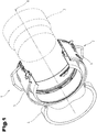
- Fig. 1 shows a perspective view of a connector assembly 1 with a connector 2, these being shown in a quarter section. Furthermore is in Fig. 1 schematically shown a mating connector 3, which can be connected to the connector assembly 1. The interaction between connector assembly 1 and a mating connector 3 is shown in FIG AT 509 196 B1 sufficiently described.
- a tube 4 is shown schematically, to which the connector 2 can be coupled.
- the tube 4 can, for example, be a rigid element, such as a plastic tube be.
- the tube 4 can be designed as a flexible line made of a rubber material.
- the connector 2 comprises a connector body 5, which is preferably formed as a one-piece formed part, for example as a deep-drawn part, in particular from a stainless steel sheet.
- the plug assembly 1 is preferably used in a motor vehicle, in particular in a road-bound motor vehicle with an internal combustion engine, such as a car or a truck.
- the connector assembly 1 is used in another application with an internal combustion engine. This can be, for example, the use of the plug assembly 1 in a stationary unit, in a ship's engine, in an aircraft engine, in a construction machine, etc.
- the plug assembly 1 can be used to connect various components of the fresh air supply to the internal combustion engine.
- the connector 2 is provided with the corresponding mating connector 3 for connecting two parts in the intake area of a turbocharger.
- such a plug assembly 1 is used in the pressure side leading from the turbocharger to connect two components.
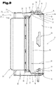
- Fig. 2 shows a cross section of the connector 2, the cut being chosen so that a locking element 6 installed in the connector 2 for securing the connector 2 and the mating connector 3 to one another can be seen.
- the locking element 6 is constructed in such a way that it can be easily activated and deactivated, so that the connector 2 and the mating connector 3 can be separated or connected to one another as required.
- the locking element 6 can be brought into a latching position in which the connector 2 and the mating connector 3 are secured to one another. Furthermore, the locking element 6 can be brought into a release position in which the mating connector 3 can be inserted into the connector 2 or removed from it.
- a reinforcing element 7 is used in the connector body 5, which serves to improve the rigidity of the connector body 5.
- the reinforcing element 7 can as in Fig. 2 clearly be designed as a sleeve segment, and therefore have an intermediate piece that is open over the circumference.
- the reinforcing element 7 can be designed as a sleeve and therefore have a closed circumference.
- Fig. 3 shows a section through the connector assembly 1 along a central longitudinal axis 8 of the connector 2.
- the plug connector 2 can comprise, in addition to the connector body 5, a plug seal 9 which is accommodated in the connector body 5.
- the plug seal 9 serves to be able to adequately seal the plug connector with the mating plug connector 3 in the plugged-together state.
- a first jacket section 10 is formed on the connector body 5, which surrounds the central longitudinal axis 8 of the connector 2 in a sleeve shape.
- the first jacket section 10 is a rotationally symmetrical hollow cylinder.
- the first jacket section 10 has an inside jacket surface 11 and an outside jacket surface 12.
- the first jacket section 10 is surrounded by a second jacket section 13, which is also rotationally symmetrical with respect to the central longitudinal axis 8.
- the first jacket section 10 is connected to the second jacket section 13 at a first end section 14 by means of a first end wall section 15.
- the first end wall section 15 can be designed in various ways. In particular, it can be provided that the first end wall section 15 is in the form of a fold, the second jacket section 13 being turned over by approximately 180 ° with respect to the first jacket section 10, as a result of which the second jacket section 13 is arranged to surround the first jacket section 10.
- the second jacket section 13 also has an inside jacket surface 16 and an outside jacket surface 17.
- the first jacket section 10 is delimited by its inside jacket surface 11 and the outside jacket surface 12, which results in a wall thickness 18 of the first jacket section 10.
- the second jacket section 13 is likewise delimited by an inside jacket surface 16 and an outside jacket surface 17, which results in a wall thickness 19 of the second jacket section 13.
- the first jacket section 10 is designed graduated in the illustrated embodiment. It can be provided that a seal receptacle 20, which is likewise formed in the connector body 5, adjoins the first jacket section 10 on the opposite side of the first end section 14 of the plug connector 2. A plug seal 9 can be accommodated in such a seal receptacle 20. It can further be provided that a third jacket section 21 adjoins the seal receptacle 20, which together with the second jacket section 13 forms an annular space 22 for receiving the tube 4.
- the second jacket section 13 and the third jacket section 21 are open to one another at a second end section 23 of the plug connector 2, which results in a pipe receiving side 24 of the connector body 5.
- the third jacket section 21 has a bevel 25 in the region of the second end section 23, which bevel is formed on the pipe receiving side 24.
- a bevel 25 has the advantage that the tube 4 or a sealing element used for sealing the tube 4 can be easily inserted into the annular space 22 in the insertion direction 26.
- the second jacket section 13 has such a bevel 27, so that the tube 4 can also be easily inserted into the annular space 22.
- the tube 4 can then be pressed with the connector body 5, so that the two components form a unit.
- the bevels 25, 27 can be realized, for example, by flanging with corresponding radii or by widening and are preferably formed during the deep-drawing process.
- the connector body 5 is preferably produced in a deep-drawing process, all wall thicknesses of the jacket sections of the connector body 5 being approximately the same size.
- the seal receptacle 20 has an end wall 28 which adjoins the third jacket section 21.
- a receptacle for the plug seal 9 can in particular be formed by the end wall 28.
- the first jacket section 10 has an outer diameter 30 and an axial extension 29.
- An inner diameter 31 of the reinforcing element 7 is preferably selected to be approximately the same size as the outer diameter 30 of the first jacket section 10.
- the connector 2 In the area of the first jacket section 10, the connector 2 has a receiving space 32.
- the receiving space 32 is surrounded by the first jacket section 10 and serves to receive part of the mating connector 3.
- the connector body 5 has a plurality of passage openings 33 which are spaced apart from one another in the circumferential direction and are likewise arranged in the region of the first jacket section 10. In the locked position of the locking element 6, which it takes up in the inserted and locked state, the locking element 6 projects through the respective passage opening 33 into the receiving space 32. In these sections, the locking element 6 interacts with a locking surface of a locking shoulder of the mating connector 3.
- the reinforcing element 7 has a recess 34 which corresponds to one of the through openings 33 and thus the locking element 6 can be carried out by the reinforcing element 7.
- a first type of passage openings 33 'and a second type of passage openings 33 are formed.
- a first type of recesses 34' and a second type of recesses 34" can be formed.
- the recess 34 ′′ of the reinforcing element 7 and the passage opening 33 ′′ of the connector body 5 have at least partially the same outer contour or are arranged congruently with one another.
- the passage opening 33 'and the recess 34' can be designed to be completely congruent, which results in a common passage opening 35.
- one or more beads 36 are introduced in the second jacket section 13 of the connector body 5, by means of which the reinforcing element 7 can be clamped in the space between the first jacket section 10 and the second jacket section 13.
- the reinforcing element 7 can be fixed in the radial direction by the beads 36 or, if necessary, can also be held in position in the axial direction by a radial clamping.
- the beads 36 can additionally contribute to increasing the stability of the second jacket section 13.
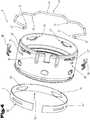
- Fig. 4 shows an exploded view of the individual components of the connector 2, again using the same reference numerals or component names for the same parts as in the previous ones Figures 1 to 3 be used. To avoid unnecessary repetition, refer to the detailed description in the previous Figures 1 to 3 pointed out or referred.
- the locking element 6 can have, for example, four latching areas 37 which are designed to protrude through the passage openings 33 of the connector body 5.
- the locking areas 37 are therefore designed as inwardly standing V-shaped elements.
- the connector 2 also includes holding elements 38, which are inserted into a holding element receptacle 39 and serve to secure the locking element 6.
- the reinforcing element 7 is in the Fig. 4 already shown prefabricated, it being pre-bent and the recesses 34 already being made in the reinforcing element 7.
- the reinforcing element 7 is designed as a sleeve segment can.
- the two recesses 34 ′′ are slot-shaped.
- the two recesses 34 ′ can have the exact same outer contour as the corresponding passage openings 33 ′.
- the recesses 34 are not or only partially introduced into the prefabricated reinforcing element 7 and that they are only formed when the reinforcing element 7 is inserted into the connector body 5.
- the reinforcing element 7 can be punched together with the connector body 5 in the inserted state.
- the reinforcing element 7 has a higher strength than the connector body 5. Since the reinforcing element 7 does not have to be deformed as much as the connector body 5, that the connector body 5 is made of a first material and the reinforcing element 7 is made of a second material, the second material having a lower deformability than the first material.
- the connector body 5 is manufactured from a flat sheet metal material by shaping, in particular by deep drawing.
- the recesses 34 and 39 arranged in the circumference of the connector body 5 can be punched in during the deep-drawing process.
- the reinforcing element 7 can also be brought into its shape by shaping.
- the passage openings 33 or the corresponding recess 34 is only produced in a subsequent stamping process when the reinforcing element 7 is already inserted in the connector body 5.
- the recess 34 and the passage opening 33 can be produced in the form of a common passage opening 35, the reinforcing element 7 and the connector body 5 wedging one another in a form-fitting manner as a result of the stamping process, and the axial positioning of the reinforcing element 7 is thereby improved.
- the recesses 34 are introduced into the reinforcing element 7 before they are inserted into the connector body 5.
- the reinforcing element 7 can be pushed into the connector body 5 in the insertion direction 26 and inserted therein. It is conceivable here that the reinforcing element 7 is inserted into a rebate area 40 which is formed in the connector body 5 in the area of the end wall section 15. A narrow slot can be formed radially through this fold area 40, into which the reinforcing element 7 can be inserted. In particular, it can be provided that the reinforcing element 7 is clamped in the fold area 40.
- the beads 36 can be used for the axial and radial positioning and fixing of the reinforcing element 7. These can be introduced into the connector body 5 in advance. In an alternative production variant, the beads 36 can also be introduced into the connector body 5 after the reinforcement element 7 has been inserted, in order to be able to clamp the reinforcement element 7.
- the locking element 6 can be inserted into the connector body 5 and then the holding elements 38 can be inserted into the connector body 5 to secure the locking element 6.
- the locking element 6 has a holding area 41, on which it can be gripped in order to be able to be inserted into the connector body 5 and to be able to be moved between the detent position and the release position.
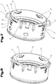
- Fig. 5 shows a perspective view of the connector 2, wherein the locking element 6 is in the locking position.
- Fig. 6 shows a detailed view of the locking element 6 which is in the locked position.
- Fig. 7 shows a perspective view of the connector 2, wherein the locking element 6 is in the release position.
- Fig. 8 shows a detailed view of the locking element 6 which is in the release position.
- the latching position of the locking element 6 is particularly good when viewed together Fig. 5 and 6 and the release position of the locking element 6 in a synopsis of Fig. 7 and 8th evident.
- the locking areas 37 protrude into the receiving space 32 and the mating connector 3 is axially secured relative to the connector 2.
- the latching areas 37 do not protrude into the receiving space 32 and the mating connector 3 is axially displaceable relative to the connector 2.
- the recess 34 in the reinforcing element 7 is slit-shaped, the slit having approximately a width which corresponds to the diameter of the locking element 6.
- the locking element 6 can be axially fixed.
- a guide pin 42 of the locking element 6 hits the holding element 38 and is thereby deflected axially, so that the locking element 6 moves into the release position.
- a bevel 43 is formed in the holding element 38, through which an axial movement into the locking element 6 is initiated when the holding area 41 is pulled radially.
- the locking element 6 can be released, the guide pin 42 on the connector body 5 or, as in FIG Fig. 8 particularly well visible, rests on the reinforcing element 7 and thus remains in the release position, the locking element 6 being prestressed.
- the locking element 6 In order to move the locking element 6 out of the release position back into the locking position, the locking element 6 can be shifted slightly axially, and due to the prestressing of the locking element 6, the locking element moves automatically back into the locking position as soon as it plunges into the recesses 34 ′ of the locking element 6 can.
Landscapes
- Engineering & Computer Science (AREA)
- General Engineering & Computer Science (AREA)
- Mechanical Engineering (AREA)
- Chemical & Material Sciences (AREA)
- Combustion & Propulsion (AREA)
- Quick-Acting Or Multi-Walled Pipe Joints (AREA)
Claims (9)
- Connecteur (2) pour la liaison de conduites pour des milieux liquides ou gazeux, avec un corps de connecteur (5), ce corps de connecteur (5) comprenant un espace annulaire (22) qui se trouve entre une première portion d'enveloppe (10) en forme de manchon, entourant en coupe transversale un axe longitudinal central (8) du connecteur (2), et une deuxième portion d'enveloppe (13) du connecteur (2), en forme de manchon, entourant en coupe transversale l'axe longitudinal central (8), dans lequel la première portion d'enveloppe (10) est entourée par la deuxième portion d'enveloppe (13) et la première portion d'enveloppe (10) du corps de connecteur (5) est reliée avec la deuxième portion d'enveloppe (13) au niveau d'une première portion d'extrémité (14) par une première portion de paroi frontale (15) et les portions d'enveloppe (10, 13) sont ouvertes l'une par rapport à l'autre au niveau d'une deuxième portion d'extrémité (23), dans lequel, dans la première portion d'enveloppe (10) et dans la deuxième portion d'enveloppe (13) sont réalisées au moins deux ouvertures de passage (33) qui sont prévues pour le logement d'un élément d'arrêt (6), cet élément d'arrêt (6) étant prévu pour la sécurisation du connecteur (2) par rapport à un contre-connecteur (3), dans lequel, dans le corps de connecteur (5), entre la première portion d'enveloppe (10) et la deuxième portion d'enveloppe (13), est inséré un élément de renfort (7), caractérisé en ce que l'élément de renfort (7) comprend au moins un évidement (34) qui correspond au moins partiellement à une des ouvertures de passage (33).
- Connecteur selon la revendication 1, caractérisé en ce que l'élément de renfort (7) est disposé au moins au niveau d'une des ouvertures de passage (33).
- Connecteur selon l'une des revendications précédentes, caractérisé en ce que le corps de connecteur (5) comprend quatre ouvertures de passage (33) qui sont conçues pour être traversées par l'élément d'arrêt (6), dans lequel l'au moins un évidement (34') de l'élément de renfort (7) est coextensif avec au moins une des ouvertures de passage (33') et constitue ainsi une ouverture de passage commune (35).
- Connecteur selon l'une des revendications précédentes, caractérisé en ce que l'au moins un évidement (34) de l'élément de renfort (7) est plus petit que l'ouverture de passage (33) correspondante.
- Connecteur selon l'une des revendications précédentes, caractérisé en ce que l'élément de renfort (7) est conçu comme un segment de manchon.
- Connecteur selon l'une des revendications précédentes, caractérisé en ce qu'un diamètre extérieur (30) de la première portion d'enveloppe (10) est égal à un diamètre intérieur (31) de l'élément de renfort (7).
- Connecteur selon l'une des revendications précédentes, caractérisé en ce que, dans la deuxième portion d'enveloppe (13) est réalisée au moins une moulure (36) au moyen de laquelle l'élément de renfort (7) est fixé dans la direction radiale.
- Connecteur selon l'une des revendications précédentes, caractérisé en ce que le corps de connecteur (5) est constitué d'un premier matériau et l'élément de renfort (7) est constitué d'un deuxième matériau, dans lequel le deuxième matériau présente une résistance supérieure à celle du premier matériau.
- Procédé de fabrication d'un connecteur selon l'une des revendications précédentes, dans lequel
dans une première étape, le corps de connecteur (5) est moulé et en option les ouvertures de passage (33) sont réalisées dans le corps de connecteur (5) ;
dans une autre étape, un élément de renfort (7) est pré-moulé ;
dans une autre étape, l'élément de renfort (7) est inséré axialement dans le corps de connecteur (5) et est positionné dans le corps de connecteur (5), caractérisé en ce que, dans une autre étape, le corps de connecteur (5) et l'élément de renfort (7) sont emboutis ensemble et une ouverture de passage commune (35) est ainsi réalisée.
Applications Claiming Priority (2)
| Application Number | Priority Date | Filing Date | Title |
|---|---|---|---|
| ATA50855/2015A AT516939B1 (de) | 2015-10-07 | 2015-10-07 | Steckverbinder zum Verbinden von Leitungen für flüssige oder gasförmige Medien |
| PCT/EP2016/073540 WO2017060184A1 (fr) | 2015-10-07 | 2016-10-03 | Raccord emmanchable pour le raccordement de conduites de matières liquides ou gazeuses |
Publications (2)
| Publication Number | Publication Date |
|---|---|
| EP3359862A1 EP3359862A1 (fr) | 2018-08-15 |
| EP3359862B1 true EP3359862B1 (fr) | 2020-05-06 |
Family
ID=57104002
Family Applications (1)
| Application Number | Title | Priority Date | Filing Date |
|---|---|---|---|
| EP16777971.9A Active EP3359862B1 (fr) | 2015-10-07 | 2016-10-03 | Raccord emmanchable pour le raccordement de conduites de matières liquides ou gazeuses |
Country Status (11)
| Country | Link |
|---|---|
| US (1) | US10927990B2 (fr) |
| EP (1) | EP3359862B1 (fr) |
| JP (1) | JP6823058B2 (fr) |
| KR (1) | KR102628363B1 (fr) |
| CN (1) | CN108139004B (fr) |
| AT (1) | AT516939B1 (fr) |
| BR (1) | BR112018005514B1 (fr) |
| ES (1) | ES2805648T3 (fr) |
| MX (1) | MX2018002810A (fr) |
| RU (1) | RU2718840C2 (fr) |
| WO (1) | WO2017060184A1 (fr) |
Families Citing this family (6)
| Publication number | Priority date | Publication date | Assignee | Title |
|---|---|---|---|---|
| AT517085B1 (de) * | 2015-10-07 | 2016-11-15 | Henn Gmbh & Co Kg | Steckverbinder zum Verbinden von Leitungen für flüssige oder gasförmige Medien |
| AT518865B1 (de) | 2017-02-13 | 2018-02-15 | Henn Gmbh & Co Kg | Steckerbaugruppe zur Verwendung in einem Fahrzeug |
| CN107289215A (zh) * | 2017-08-24 | 2017-10-24 | 潍柴动力股份有限公司 | 一种管路接口连接装置及发动机 |
| EP3584489B1 (fr) * | 2018-06-19 | 2023-07-26 | MANN+HUMMEL GmbH | Agencement de couplage et connecteur pour un agencement de couplage |
| AT522804B1 (de) * | 2019-09-03 | 2021-02-15 | Henn Gmbh & Co Kg | Steckverbinder zum Verbinden von Leitungen für flüssige oder gasförmige Medien |
| CN112338075B (zh) * | 2020-11-25 | 2022-09-02 | 重庆工程职业技术学院 | 一种卡紧模块及其消防风管咬口机 |
Citations (1)
| Publication number | Priority date | Publication date | Assignee | Title |
|---|---|---|---|---|
| WO2005045299A1 (fr) * | 2003-10-08 | 2005-05-19 | Henn Gmbh & Co. Kg | Raccord a emboitement pour conduites tubulaires ou en tuyaux souples, a guidage a ressort d'arret |
Family Cites Families (20)
| Publication number | Priority date | Publication date | Assignee | Title |
|---|---|---|---|---|
| US4423891A (en) * | 1981-09-28 | 1984-01-03 | Menges William H | Corrugated hose coupling |
| JPH0624631Y2 (ja) | 1990-09-11 | 1994-06-29 | 信越ポリマー株式会社 | 捻り管継手 |
| ATE119981T1 (de) * | 1991-04-29 | 1995-04-15 | Caillau Ets | Verbindungselement zur schnellkupplung eines rohres. |
| JP2565714Y2 (ja) | 1992-04-16 | 1998-03-18 | 日本鋼管株式会社 | 配管用継手 |
| DE19522690A1 (de) * | 1995-06-22 | 1997-01-02 | Henn Gmbh & Co Kg | Steckverbindung für den Anschluß von Rohr- und Schlauchleitungen |
| DE10347929A1 (de) | 2003-10-15 | 2005-05-19 | Henn Gmbh & Co. Kg | Steckverbindung für Rohr- und Schlauchleitungen mit verstärktem Materialquerschnitt |
| JP4428625B2 (ja) | 2003-12-26 | 2010-03-10 | 株式会社オンダ製作所 | 樹脂製ヘッダーの接続部における補強構造 |
| DE102004016599B3 (de) | 2004-04-03 | 2005-09-08 | Henn Gmbh & Co. Kg | Steckverbindung mit Winkelarretierung |
| DE102004019800A1 (de) | 2004-04-23 | 2005-11-24 | Henn Gmbh & Co. Kg | Steckverbindung mit einem Formdichtring |
| DE102004019799A1 (de) | 2004-04-23 | 2005-11-17 | Henn Gmbh & Co. Kg | Verfahren zur Herstellung einer Steckverbindung und Steckverbindung |
| US20080191481A1 (en) * | 2005-04-13 | 2008-08-14 | Henn Gmbh & Co. Kg | Method for Production of a Plug Connection and a Plug Connection |
| DE102006019257B4 (de) | 2006-04-26 | 2010-08-05 | A. Raymond Et Cie | Fluidleitungskupplung |
| WO2009094679A1 (fr) | 2008-01-28 | 2009-08-06 | Henn Gmbh & Co Kg. | Accouplement par emboîtement pour raccordement de conduites d'eau de refroidissement de moteurs à combustion interne |
| DE102008027204B4 (de) | 2008-06-06 | 2017-04-13 | Bayerische Motoren Werke Aktiengesellschaft | Schlauchkupplung |
| AT508669B1 (de) * | 2010-02-12 | 2011-03-15 | Henn Gmbh & Co Kg | Steckverbinder |
| AT509561B1 (de) | 2010-03-04 | 2012-07-15 | Henn Gmbh & Co Kg | Verfahren bei dem ein leitungsverbinder, insbesondere steckverbinder, von einer befestigungsvorrichtung an einer leitung für flüssige und/oder gasförmige medien befestigt wird |
| AT509196B1 (de) | 2010-03-12 | 2011-07-15 | Henn Gmbh & Co Kg | Verfahren zum verbinden eines endabschnitts einer leitung für flüssige oder gasförmige medien mit einem steckverbinder |
| SE534794C2 (sv) | 2010-04-01 | 2011-12-27 | Atlas Copco Rock Drills Ab | Hydraulisk slående anordning, kolvstyrning, samt borrigg |
| AT512397B1 (de) | 2012-05-07 | 2013-08-15 | Henn Gmbh & Co Kg | Steckverbindung zum Verbinden von Leitungen für unter Druck gesetzte Flüssigkeiten oder Gase |
| JP6147210B2 (ja) | 2014-03-17 | 2017-06-14 | 株式会社ニフコ | 管状体のロック機構 |
-
2015
- 2015-10-07 AT ATA50855/2015A patent/AT516939B1/de active
-
2016
- 2016-10-03 EP EP16777971.9A patent/EP3359862B1/fr active Active
- 2016-10-03 JP JP2018518461A patent/JP6823058B2/ja active Active
- 2016-10-03 BR BR112018005514-0A patent/BR112018005514B1/pt active IP Right Grant
- 2016-10-03 WO PCT/EP2016/073540 patent/WO2017060184A1/fr active Application Filing
- 2016-10-03 CN CN201680056382.7A patent/CN108139004B/zh active Active
- 2016-10-03 KR KR1020187012888A patent/KR102628363B1/ko active IP Right Grant
- 2016-10-03 RU RU2018115903A patent/RU2718840C2/ru active
- 2016-10-03 MX MX2018002810A patent/MX2018002810A/es unknown
- 2016-10-03 US US15/766,502 patent/US10927990B2/en active Active
- 2016-10-03 ES ES16777971T patent/ES2805648T3/es active Active
Patent Citations (1)
| Publication number | Priority date | Publication date | Assignee | Title |
|---|---|---|---|---|
| WO2005045299A1 (fr) * | 2003-10-08 | 2005-05-19 | Henn Gmbh & Co. Kg | Raccord a emboitement pour conduites tubulaires ou en tuyaux souples, a guidage a ressort d'arret |
Also Published As
| Publication number | Publication date |
|---|---|
| CN108139004A (zh) | 2018-06-08 |
| CN108139004B (zh) | 2019-11-05 |
| US20180299050A1 (en) | 2018-10-18 |
| RU2718840C2 (ru) | 2020-04-14 |
| BR112018005514A2 (pt) | 2018-12-11 |
| ES2805648T3 (es) | 2021-02-15 |
| KR102628363B1 (ko) | 2024-01-24 |
| JP2018529908A (ja) | 2018-10-11 |
| RU2018115903A (ru) | 2019-11-07 |
| MX2018002810A (es) | 2018-07-03 |
| RU2018115903A3 (fr) | 2020-02-04 |
| US10927990B2 (en) | 2021-02-23 |
| WO2017060184A1 (fr) | 2017-04-13 |
| KR20180099630A (ko) | 2018-09-05 |
| JP6823058B2 (ja) | 2021-01-27 |
| EP3359862A1 (fr) | 2018-08-15 |
| AT516939B1 (de) | 2016-10-15 |
| BR112018005514B1 (pt) | 2021-10-19 |
| AT516939A4 (de) | 2016-10-15 |
Similar Documents
| Publication | Publication Date | Title |
|---|---|---|
| EP3359862B1 (fr) | Raccord emmanchable pour le raccordement de conduites de matières liquides ou gazeuses | |
| EP3359863B1 (fr) | Raccord emmanchable pour le raccordement de conduites de matières liquides ou gazeuses | |
| EP3580487B1 (fr) | Module connecteur destiné à être utilisé dans un véhicule | |
| WO2012175438A1 (fr) | Élément filtrant en plaque | |
| EP3265713B1 (fr) | Ensemble de raccord enfichable servant à raccorder des conduits | |
| DE102019122989A1 (de) | Deflektor für einen Diffusor eines Gasgenerators, Diffusor-Deflektor Baugruppe mit einem solchen Deflektor, Gasgenerator mit einer solchen Diffusor-Deflektor Baugruppe, Herstellungsverfahren und Montageverfahren | |
| EP3107794B1 (fr) | Direction de véhicule automobile et procédé de montage d'une direction de véhicule automobile | |
| DE102011076369A1 (de) | Untere Abdeckung eines Kühlkanals eines Kolbens | |
| EP4025817B1 (fr) | Pièce de raccord enfichable et pièce de raccord enfichable conjuguée pour relier des conduites pour substances liquides ou gazeuses | |
| DE102015105091A1 (de) | Überrollschutzsystem für ein Kraftfahrzeug | |
| DE202021100271U1 (de) | Gegensteckverbinder zum Verbinden von Bauteilen für flüssige oder gasförmige Medien, sowie eine Steckerbaugruppe | |
| DE102016214206A1 (de) | Vorrichtung zur Tilgung von Schwingungsresonanzen | |
| DE102009028999A1 (de) | Hydraulische Komponente mit mindestens zwei Bereichen unterschiedlichen Drucks und mindestens einem Funktionselement | |
| DE102019219008A1 (de) | Verstellbare Lenksäule für ein Kraftfahrzeug | |
| AT522335B1 (de) | Steckerbaugruppe zur Verwendung in einem Verbrennungsmotor | |
| DE102015205429A1 (de) | Gasleitelement und Verfahren zum Herstellen einer Gasgeneratoranordnung | |
| EP1321202B1 (fr) | Procédé de fabrication et dispositif de formage à haute pression interne pour la mise en oeuvre du procédé de fabrication | |
| DE102015116961A1 (de) | Rohrkappensatz und Anordnung mit einem solchen | |
| DE102015223190A1 (de) | Rohbaustruktur eines Kraftfahrzeugs mit einem Stoßfänger | |
| DE202005016777U1 (de) | Befestigungsanordnung und Kraftfahrzeug | |
| DE102015100928B4 (de) | Karosserieanordnung für ein Kraftfahrzeug sowie Verfahren zum Herstellen einer solchen Karosserieanordnung | |
| DE102020201086A1 (de) | Belüftungseinrichtung für ein Kraftfahrzeug, Helmholtzresonator und Vorrichtung zum Herstellen | |
| DE102014109724A1 (de) | Kraftfahrzeugkarosserieteil | |
| DE102019205257A1 (de) | Robuster Steckverbinder für medienführende Leitungen, Steckverbindungsanordnung und Kraftstoffinjektor | |
| WO2017214654A1 (fr) | Tuyau à collet et bride tournante |
Legal Events
| Date | Code | Title | Description |
|---|---|---|---|
| STAA | Information on the status of an ep patent application or granted ep patent |
Free format text: STATUS: THE INTERNATIONAL PUBLICATION HAS BEEN MADE |
|
| PUAI | Public reference made under article 153(3) epc to a published international application that has entered the european phase |
Free format text: ORIGINAL CODE: 0009012 |
|
| STAA | Information on the status of an ep patent application or granted ep patent |
Free format text: STATUS: REQUEST FOR EXAMINATION WAS MADE |
|
| 17P | Request for examination filed |
Effective date: 20180504 |
|
| AK | Designated contracting states |
Kind code of ref document: A1 Designated state(s): AL AT BE BG CH CY CZ DE DK EE ES FI FR GB GR HR HU IE IS IT LI LT LU LV MC MK MT NL NO PL PT RO RS SE SI SK SM TR |
|
| AX | Request for extension of the european patent |
Extension state: BA ME |
|
| DAV | Request for validation of the european patent (deleted) | ||
| DAX | Request for extension of the european patent (deleted) | ||
| STAA | Information on the status of an ep patent application or granted ep patent |
Free format text: STATUS: EXAMINATION IS IN PROGRESS |
|
| 17Q | First examination report despatched |
Effective date: 20190326 |
|
| GRAP | Despatch of communication of intention to grant a patent |
Free format text: ORIGINAL CODE: EPIDOSNIGR1 |
|
| STAA | Information on the status of an ep patent application or granted ep patent |
Free format text: STATUS: GRANT OF PATENT IS INTENDED |
|
| INTG | Intention to grant announced |
Effective date: 20191213 |
|
| GRAS | Grant fee paid |
Free format text: ORIGINAL CODE: EPIDOSNIGR3 |
|
| GRAA | (expected) grant |
Free format text: ORIGINAL CODE: 0009210 |
|
| STAA | Information on the status of an ep patent application or granted ep patent |
Free format text: STATUS: THE PATENT HAS BEEN GRANTED |
|
| AK | Designated contracting states |
Kind code of ref document: B1 Designated state(s): AL AT BE BG CH CY CZ DE DK EE ES FI FR GB GR HR HU IE IS IT LI LT LU LV MC MK MT NL NO PL PT RO RS SE SI SK SM TR |
|
| REG | Reference to a national code |
Ref country code: GB Ref legal event code: FG4D Free format text: NOT ENGLISH |
|
| REG | Reference to a national code |
Ref country code: CH Ref legal event code: EP Ref country code: AT Ref legal event code: REF Ref document number: 1267301 Country of ref document: AT Kind code of ref document: T Effective date: 20200515 |
|
| REG | Reference to a national code |
Ref country code: DE Ref legal event code: R096 Ref document number: 502016009887 Country of ref document: DE |
|
| REG | Reference to a national code |
Ref country code: IE Ref legal event code: FG4D Free format text: LANGUAGE OF EP DOCUMENT: GERMAN |
|
| REG | Reference to a national code |
Ref country code: LT Ref legal event code: MG4D |
|
| REG | Reference to a national code |
Ref country code: NL Ref legal event code: MP Effective date: 20200506 |
|
| PG25 | Lapsed in a contracting state [announced via postgrant information from national office to epo] |
Ref country code: LT Free format text: LAPSE BECAUSE OF FAILURE TO SUBMIT A TRANSLATION OF THE DESCRIPTION OR TO PAY THE FEE WITHIN THE PRESCRIBED TIME-LIMIT Effective date: 20200506 Ref country code: NO Free format text: LAPSE BECAUSE OF FAILURE TO SUBMIT A TRANSLATION OF THE DESCRIPTION OR TO PAY THE FEE WITHIN THE PRESCRIBED TIME-LIMIT Effective date: 20200806 Ref country code: SE Free format text: LAPSE BECAUSE OF FAILURE TO SUBMIT A TRANSLATION OF THE DESCRIPTION OR TO PAY THE FEE WITHIN THE PRESCRIBED TIME-LIMIT Effective date: 20200506 Ref country code: GR Free format text: LAPSE BECAUSE OF FAILURE TO SUBMIT A TRANSLATION OF THE DESCRIPTION OR TO PAY THE FEE WITHIN THE PRESCRIBED TIME-LIMIT Effective date: 20200807 Ref country code: IS Free format text: LAPSE BECAUSE OF FAILURE TO SUBMIT A TRANSLATION OF THE DESCRIPTION OR TO PAY THE FEE WITHIN THE PRESCRIBED TIME-LIMIT Effective date: 20200906 Ref country code: FI Free format text: LAPSE BECAUSE OF FAILURE TO SUBMIT A TRANSLATION OF THE DESCRIPTION OR TO PAY THE FEE WITHIN THE PRESCRIBED TIME-LIMIT Effective date: 20200506 Ref country code: PT Free format text: LAPSE BECAUSE OF FAILURE TO SUBMIT A TRANSLATION OF THE DESCRIPTION OR TO PAY THE FEE WITHIN THE PRESCRIBED TIME-LIMIT Effective date: 20200907 |
|
| PG25 | Lapsed in a contracting state [announced via postgrant information from national office to epo] |
Ref country code: RS Free format text: LAPSE BECAUSE OF FAILURE TO SUBMIT A TRANSLATION OF THE DESCRIPTION OR TO PAY THE FEE WITHIN THE PRESCRIBED TIME-LIMIT Effective date: 20200506 Ref country code: HR Free format text: LAPSE BECAUSE OF FAILURE TO SUBMIT A TRANSLATION OF THE DESCRIPTION OR TO PAY THE FEE WITHIN THE PRESCRIBED TIME-LIMIT Effective date: 20200506 Ref country code: LV Free format text: LAPSE BECAUSE OF FAILURE TO SUBMIT A TRANSLATION OF THE DESCRIPTION OR TO PAY THE FEE WITHIN THE PRESCRIBED TIME-LIMIT Effective date: 20200506 Ref country code: BG Free format text: LAPSE BECAUSE OF FAILURE TO SUBMIT A TRANSLATION OF THE DESCRIPTION OR TO PAY THE FEE WITHIN THE PRESCRIBED TIME-LIMIT Effective date: 20200806 |
|
| PG25 | Lapsed in a contracting state [announced via postgrant information from national office to epo] |
Ref country code: AL Free format text: LAPSE BECAUSE OF FAILURE TO SUBMIT A TRANSLATION OF THE DESCRIPTION OR TO PAY THE FEE WITHIN THE PRESCRIBED TIME-LIMIT Effective date: 20200506 Ref country code: NL Free format text: LAPSE BECAUSE OF FAILURE TO SUBMIT A TRANSLATION OF THE DESCRIPTION OR TO PAY THE FEE WITHIN THE PRESCRIBED TIME-LIMIT Effective date: 20200506 |
|
| PG25 | Lapsed in a contracting state [announced via postgrant information from national office to epo] |
Ref country code: EE Free format text: LAPSE BECAUSE OF FAILURE TO SUBMIT A TRANSLATION OF THE DESCRIPTION OR TO PAY THE FEE WITHIN THE PRESCRIBED TIME-LIMIT Effective date: 20200506 Ref country code: RO Free format text: LAPSE BECAUSE OF FAILURE TO SUBMIT A TRANSLATION OF THE DESCRIPTION OR TO PAY THE FEE WITHIN THE PRESCRIBED TIME-LIMIT Effective date: 20200506 Ref country code: DK Free format text: LAPSE BECAUSE OF FAILURE TO SUBMIT A TRANSLATION OF THE DESCRIPTION OR TO PAY THE FEE WITHIN THE PRESCRIBED TIME-LIMIT Effective date: 20200506 Ref country code: SM Free format text: LAPSE BECAUSE OF FAILURE TO SUBMIT A TRANSLATION OF THE DESCRIPTION OR TO PAY THE FEE WITHIN THE PRESCRIBED TIME-LIMIT Effective date: 20200506 |
|
| REG | Reference to a national code |
Ref country code: DE Ref legal event code: R097 Ref document number: 502016009887 Country of ref document: DE |
|
| REG | Reference to a national code |
Ref country code: ES Ref legal event code: FG2A Ref document number: 2805648 Country of ref document: ES Kind code of ref document: T3 Effective date: 20210215 |
|
| PG25 | Lapsed in a contracting state [announced via postgrant information from national office to epo] |
Ref country code: PL Free format text: LAPSE BECAUSE OF FAILURE TO SUBMIT A TRANSLATION OF THE DESCRIPTION OR TO PAY THE FEE WITHIN THE PRESCRIBED TIME-LIMIT Effective date: 20200506 Ref country code: SK Free format text: LAPSE BECAUSE OF FAILURE TO SUBMIT A TRANSLATION OF THE DESCRIPTION OR TO PAY THE FEE WITHIN THE PRESCRIBED TIME-LIMIT Effective date: 20200506 |
|
| PLBE | No opposition filed within time limit |
Free format text: ORIGINAL CODE: 0009261 |
|
| STAA | Information on the status of an ep patent application or granted ep patent |
Free format text: STATUS: NO OPPOSITION FILED WITHIN TIME LIMIT |
|
| 26N | No opposition filed |
Effective date: 20210209 |
|
| PG25 | Lapsed in a contracting state [announced via postgrant information from national office to epo] |
Ref country code: SI Free format text: LAPSE BECAUSE OF FAILURE TO SUBMIT A TRANSLATION OF THE DESCRIPTION OR TO PAY THE FEE WITHIN THE PRESCRIBED TIME-LIMIT Effective date: 20200506 |
|
| REG | Reference to a national code |
Ref country code: CH Ref legal event code: PL |
|
| PG25 | Lapsed in a contracting state [announced via postgrant information from national office to epo] |
Ref country code: MC Free format text: LAPSE BECAUSE OF FAILURE TO SUBMIT A TRANSLATION OF THE DESCRIPTION OR TO PAY THE FEE WITHIN THE PRESCRIBED TIME-LIMIT Effective date: 20200506 Ref country code: LU Free format text: LAPSE BECAUSE OF NON-PAYMENT OF DUE FEES Effective date: 20201003 |
|
| REG | Reference to a national code |
Ref country code: BE Ref legal event code: MM Effective date: 20201031 |
|
| PG25 | Lapsed in a contracting state [announced via postgrant information from national office to epo] |
Ref country code: CH Free format text: LAPSE BECAUSE OF NON-PAYMENT OF DUE FEES Effective date: 20201031 Ref country code: BE Free format text: LAPSE BECAUSE OF NON-PAYMENT OF DUE FEES Effective date: 20201031 Ref country code: LI Free format text: LAPSE BECAUSE OF NON-PAYMENT OF DUE FEES Effective date: 20201031 |
|
| PG25 | Lapsed in a contracting state [announced via postgrant information from national office to epo] |
Ref country code: IE Free format text: LAPSE BECAUSE OF NON-PAYMENT OF DUE FEES Effective date: 20201003 |
|
| PG25 | Lapsed in a contracting state [announced via postgrant information from national office to epo] |
Ref country code: TR Free format text: LAPSE BECAUSE OF FAILURE TO SUBMIT A TRANSLATION OF THE DESCRIPTION OR TO PAY THE FEE WITHIN THE PRESCRIBED TIME-LIMIT Effective date: 20200506 Ref country code: MT Free format text: LAPSE BECAUSE OF FAILURE TO SUBMIT A TRANSLATION OF THE DESCRIPTION OR TO PAY THE FEE WITHIN THE PRESCRIBED TIME-LIMIT Effective date: 20200506 Ref country code: CY Free format text: LAPSE BECAUSE OF FAILURE TO SUBMIT A TRANSLATION OF THE DESCRIPTION OR TO PAY THE FEE WITHIN THE PRESCRIBED TIME-LIMIT Effective date: 20200506 |
|
| PG25 | Lapsed in a contracting state [announced via postgrant information from national office to epo] |
Ref country code: MK Free format text: LAPSE BECAUSE OF FAILURE TO SUBMIT A TRANSLATION OF THE DESCRIPTION OR TO PAY THE FEE WITHIN THE PRESCRIBED TIME-LIMIT Effective date: 20200506 |
|
| REG | Reference to a national code |
Ref country code: AT Ref legal event code: MM01 Ref document number: 1267301 Country of ref document: AT Kind code of ref document: T Effective date: 20211003 |
|
| PG25 | Lapsed in a contracting state [announced via postgrant information from national office to epo] |
Ref country code: AT Free format text: LAPSE BECAUSE OF NON-PAYMENT OF DUE FEES Effective date: 20211003 |
|
| P01 | Opt-out of the competence of the unified patent court (upc) registered |
Effective date: 20230530 |
|
| PGFP | Annual fee paid to national office [announced via postgrant information from national office to epo] |
Ref country code: GB Payment date: 20230907 Year of fee payment: 8 Ref country code: CZ Payment date: 20230823 Year of fee payment: 8 |
|
| PGFP | Annual fee paid to national office [announced via postgrant information from national office to epo] |
Ref country code: FR Payment date: 20230907 Year of fee payment: 8 |
|
| PGFP | Annual fee paid to national office [announced via postgrant information from national office to epo] |
Ref country code: ES Payment date: 20231108 Year of fee payment: 8 |
|
| PGFP | Annual fee paid to national office [announced via postgrant information from national office to epo] |
Ref country code: IT Payment date: 20231023 Year of fee payment: 8 Ref country code: DE Payment date: 20230904 Year of fee payment: 8 |