EP3359048B1 - Système acoustique de suivi orthopédique et méthodes associées - Google Patents
Système acoustique de suivi orthopédique et méthodes associées Download PDFInfo
- Publication number
- EP3359048B1 EP3359048B1 EP16854507.7A EP16854507A EP3359048B1 EP 3359048 B1 EP3359048 B1 EP 3359048B1 EP 16854507 A EP16854507 A EP 16854507A EP 3359048 B1 EP3359048 B1 EP 3359048B1
- Authority
- EP
- European Patent Office
- Prior art keywords
- acoustic
- waveforms
- array
- bone
- transducer elements
- Prior art date
- Legal status (The legal status is an assumption and is not a legal conclusion. Google has not performed a legal analysis and makes no representation as to the accuracy of the status listed.)
- Active
Links
- 230000000399 orthopedic effect Effects 0.000 title claims description 84
- 238000000034 method Methods 0.000 title claims description 75
- 210000000988 bone and bone Anatomy 0.000 claims description 170
- 230000005540 biological transmission Effects 0.000 claims description 122
- 238000012545 processing Methods 0.000 claims description 111
- 238000002592 echocardiography Methods 0.000 claims description 81
- 239000000523 sample Substances 0.000 claims description 45
- 230000008878 coupling Effects 0.000 claims description 44
- 238000010168 coupling process Methods 0.000 claims description 44
- 238000005859 coupling reaction Methods 0.000 claims description 44
- 238000004891 communication Methods 0.000 claims description 42
- 230000033001 locomotion Effects 0.000 claims description 36
- 239000000463 material Substances 0.000 claims description 29
- 230000007274 generation of a signal involved in cell-cell signaling Effects 0.000 claims description 25
- 230000008569 process Effects 0.000 claims description 24
- 239000000017 hydrogel Substances 0.000 claims description 23
- 210000004872 soft tissue Anatomy 0.000 claims description 23
- 210000001519 tissue Anatomy 0.000 claims description 20
- 230000003287 optical effect Effects 0.000 claims description 13
- 239000002131 composite material Substances 0.000 claims description 9
- 238000012546 transfer Methods 0.000 claims description 9
- 239000013598 vector Substances 0.000 claims description 7
- 230000002463 transducing effect Effects 0.000 claims description 6
- 238000012876 topography Methods 0.000 claims description 5
- 239000012530 fluid Substances 0.000 claims description 3
- 238000004519 manufacturing process Methods 0.000 claims description 2
- 238000002604 ultrasonography Methods 0.000 description 56
- 210000000689 upper leg Anatomy 0.000 description 41
- 238000005516 engineering process Methods 0.000 description 32
- 230000006870 function Effects 0.000 description 30
- 210000002303 tibia Anatomy 0.000 description 27
- 238000003384 imaging method Methods 0.000 description 26
- 238000003491 array Methods 0.000 description 24
- 238000010586 diagram Methods 0.000 description 23
- 238000005259 measurement Methods 0.000 description 21
- 230000000875 corresponding effect Effects 0.000 description 19
- 210000002414 leg Anatomy 0.000 description 17
- 238000001228 spectrum Methods 0.000 description 14
- 238000001356 surgical procedure Methods 0.000 description 14
- 238000004422 calculation algorithm Methods 0.000 description 13
- 239000007787 solid Substances 0.000 description 11
- 238000012360 testing method Methods 0.000 description 11
- 244000309466 calf Species 0.000 description 10
- 238000012285 ultrasound imaging Methods 0.000 description 10
- 238000004590 computer program Methods 0.000 description 9
- 230000001934 delay Effects 0.000 description 9
- 230000001427 coherent effect Effects 0.000 description 8
- 238000013461 design Methods 0.000 description 8
- 238000005070 sampling Methods 0.000 description 8
- 230000001133 acceleration Effects 0.000 description 7
- 238000002591 computed tomography Methods 0.000 description 7
- 229920001971 elastomer Polymers 0.000 description 7
- 210000003127 knee Anatomy 0.000 description 7
- 238000003860 storage Methods 0.000 description 7
- 230000001419 dependent effect Effects 0.000 description 6
- 239000005060 rubber Substances 0.000 description 6
- 230000008054 signal transmission Effects 0.000 description 6
- 238000011883 total knee arthroplasty Methods 0.000 description 6
- XLYOFNOQVPJJNP-UHFFFAOYSA-N water Substances O XLYOFNOQVPJJNP-UHFFFAOYSA-N 0.000 description 6
- 230000015572 biosynthetic process Effects 0.000 description 5
- 239000000835 fiber Substances 0.000 description 5
- 239000000499 gel Substances 0.000 description 5
- 238000012544 monitoring process Methods 0.000 description 5
- 229920000642 polymer Polymers 0.000 description 5
- 230000009466 transformation Effects 0.000 description 5
- 238000000844 transformation Methods 0.000 description 5
- 210000003484 anatomy Anatomy 0.000 description 4
- 210000003423 ankle Anatomy 0.000 description 4
- 238000013459 approach Methods 0.000 description 4
- 230000010365 information processing Effects 0.000 description 4
- 210000000629 knee joint Anatomy 0.000 description 4
- 210000003205 muscle Anatomy 0.000 description 4
- 238000013439 planning Methods 0.000 description 4
- 230000001225 therapeutic effect Effects 0.000 description 4
- 230000000007 visual effect Effects 0.000 description 4
- QTBSBXVTEAMEQO-UHFFFAOYSA-N Acetic acid Chemical compound CC(O)=O QTBSBXVTEAMEQO-UHFFFAOYSA-N 0.000 description 3
- IAZDPXIOMUYVGZ-UHFFFAOYSA-N Dimethylsulphoxide Chemical compound CS(C)=O IAZDPXIOMUYVGZ-UHFFFAOYSA-N 0.000 description 3
- 241001465754 Metazoa Species 0.000 description 3
- DNIAPMSPPWPWGF-UHFFFAOYSA-N Propylene glycol Chemical compound CC(O)CO DNIAPMSPPWPWGF-UHFFFAOYSA-N 0.000 description 3
- 230000008901 benefit Effects 0.000 description 3
- 210000000481 breast Anatomy 0.000 description 3
- 150000001875 compounds Chemical class 0.000 description 3
- 230000001054 cortical effect Effects 0.000 description 3
- 230000006378 damage Effects 0.000 description 3
- 230000003111 delayed effect Effects 0.000 description 3
- 230000002939 deleterious effect Effects 0.000 description 3
- 210000001624 hip Anatomy 0.000 description 3
- 208000015181 infectious disease Diseases 0.000 description 3
- 230000003993 interaction Effects 0.000 description 3
- 229910052451 lead zirconate titanate Inorganic materials 0.000 description 3
- 239000007788 liquid Substances 0.000 description 3
- 239000011159 matrix material Substances 0.000 description 3
- 229910052751 metal Inorganic materials 0.000 description 3
- 239000002184 metal Substances 0.000 description 3
- 238000005457 optimization Methods 0.000 description 3
- 239000002245 particle Substances 0.000 description 3
- 239000004033 plastic Substances 0.000 description 3
- 229920003023 plastic Polymers 0.000 description 3
- 229920002635 polyurethane Polymers 0.000 description 3
- 239000004814 polyurethane Substances 0.000 description 3
- 230000002829 reductive effect Effects 0.000 description 3
- 238000000926 separation method Methods 0.000 description 3
- 230000003595 spectral effect Effects 0.000 description 3
- 230000001954 sterilising effect Effects 0.000 description 3
- 238000004659 sterilization and disinfection Methods 0.000 description 3
- 230000002123 temporal effect Effects 0.000 description 3
- QGZKDVFQNNGYKY-UHFFFAOYSA-N Ammonia Chemical compound N QGZKDVFQNNGYKY-UHFFFAOYSA-N 0.000 description 2
- 208000034656 Contusions Diseases 0.000 description 2
- LFQSCWFLJHTTHZ-UHFFFAOYSA-N Ethanol Chemical compound CCO LFQSCWFLJHTTHZ-UHFFFAOYSA-N 0.000 description 2
- SXRSQZLOMIGNAQ-UHFFFAOYSA-N Glutaraldehyde Chemical compound O=CCCCC=O SXRSQZLOMIGNAQ-UHFFFAOYSA-N 0.000 description 2
- 230000005355 Hall effect Effects 0.000 description 2
- CSNNHWWHGAXBCP-UHFFFAOYSA-L Magnesium sulfate Chemical compound [Mg+2].[O-][S+2]([O-])([O-])[O-] CSNNHWWHGAXBCP-UHFFFAOYSA-L 0.000 description 2
- KWYHDKDOAIKMQN-UHFFFAOYSA-N N,N,N',N'-tetramethylethylenediamine Chemical compound CN(C)CCN(C)C KWYHDKDOAIKMQN-UHFFFAOYSA-N 0.000 description 2
- 206010028980 Neoplasm Diseases 0.000 description 2
- 239000002033 PVDF binder Substances 0.000 description 2
- 244000286916 Ratibida columnifera Species 0.000 description 2
- 235000009413 Ratibida columnifera Nutrition 0.000 description 2
- FAPWRFPIFSIZLT-UHFFFAOYSA-M Sodium chloride Chemical compound [Na+].[Cl-] FAPWRFPIFSIZLT-UHFFFAOYSA-M 0.000 description 2
- 208000010040 Sprains and Strains Diseases 0.000 description 2
- 239000000853 adhesive Substances 0.000 description 2
- 230000001070 adhesive effect Effects 0.000 description 2
- 230000009286 beneficial effect Effects 0.000 description 2
- 239000000872 buffer Substances 0.000 description 2
- OSGAYBCDTDRGGQ-UHFFFAOYSA-L calcium sulfate Chemical compound [Ca+2].[O-]S([O-])(=O)=O OSGAYBCDTDRGGQ-UHFFFAOYSA-L 0.000 description 2
- 239000000919 ceramic Substances 0.000 description 2
- 230000008859 change Effects 0.000 description 2
- 239000011538 cleaning material Substances 0.000 description 2
- 230000000295 complement effect Effects 0.000 description 2
- 239000000356 contaminant Substances 0.000 description 2
- 239000013078 crystal Substances 0.000 description 2
- 238000013500 data storage Methods 0.000 description 2
- 238000000354 decomposition reaction Methods 0.000 description 2
- 230000001627 detrimental effect Effects 0.000 description 2
- 230000004069 differentiation Effects 0.000 description 2
- NKZSPGSOXYXWQA-UHFFFAOYSA-N dioxido(oxo)titanium;lead(2+) Chemical compound [Pb+2].[O-][Ti]([O-])=O NKZSPGSOXYXWQA-UHFFFAOYSA-N 0.000 description 2
- 235000019800 disodium phosphate Nutrition 0.000 description 2
- 238000006073 displacement reaction Methods 0.000 description 2
- 239000011521 glass Substances 0.000 description 2
- 230000003862 health status Effects 0.000 description 2
- 210000001981 hip bone Anatomy 0.000 description 2
- 239000007943 implant Substances 0.000 description 2
- 230000010354 integration Effects 0.000 description 2
- 238000013150 knee replacement Methods 0.000 description 2
- 229920000126 latex Polymers 0.000 description 2
- 238000012417 linear regression Methods 0.000 description 2
- 238000012423 maintenance Methods 0.000 description 2
- 210000003739 neck Anatomy 0.000 description 2
- 229920001084 poly(chloroprene) Polymers 0.000 description 2
- 229920002981 polyvinylidene fluoride Polymers 0.000 description 2
- 238000003672 processing method Methods 0.000 description 2
- 230000009467 reduction Effects 0.000 description 2
- 229920005989 resin Polymers 0.000 description 2
- 239000011347 resin Substances 0.000 description 2
- 230000004044 response Effects 0.000 description 2
- 230000037390 scarring Effects 0.000 description 2
- 238000013515 script Methods 0.000 description 2
- 239000000126 substance Substances 0.000 description 2
- 238000003786 synthesis reaction Methods 0.000 description 2
- 238000002560 therapeutic procedure Methods 0.000 description 2
- 230000036962 time dependent Effects 0.000 description 2
- 238000010361 transduction Methods 0.000 description 2
- 230000026683 transduction Effects 0.000 description 2
- 238000013519 translation Methods 0.000 description 2
- IXPNQXFRVYWDDI-UHFFFAOYSA-N 1-methyl-2,4-dioxo-1,3-diazinane-5-carboximidamide Chemical compound CN1CC(C(N)=N)C(=O)NC1=O IXPNQXFRVYWDDI-UHFFFAOYSA-N 0.000 description 1
- 238000010146 3D printing Methods 0.000 description 1
- HRPVXLWXLXDGHG-UHFFFAOYSA-N Acrylamide Chemical compound NC(=O)C=C HRPVXLWXLXDGHG-UHFFFAOYSA-N 0.000 description 1
- 235000002961 Aloe barbadensis Nutrition 0.000 description 1
- 244000186892 Aloe vera Species 0.000 description 1
- 238000012935 Averaging Methods 0.000 description 1
- 241000282465 Canis Species 0.000 description 1
- 229920001661 Chitosan Polymers 0.000 description 1
- 229920000742 Cotton Polymers 0.000 description 1
- FBPFZTCFMRRESA-FSIIMWSLSA-N D-Glucitol Natural products OC[C@H](O)[C@H](O)[C@@H](O)[C@H](O)CO FBPFZTCFMRRESA-FSIIMWSLSA-N 0.000 description 1
- FBPFZTCFMRRESA-JGWLITMVSA-N D-glucitol Chemical compound OC[C@H](O)[C@@H](O)[C@H](O)[C@H](O)CO FBPFZTCFMRRESA-JGWLITMVSA-N 0.000 description 1
- 239000004593 Epoxy Substances 0.000 description 1
- WQZGKKKJIJFFOK-GASJEMHNSA-N Glucose Natural products OC[C@H]1OC(O)[C@H](O)[C@@H](O)[C@@H]1O WQZGKKKJIJFFOK-GASJEMHNSA-N 0.000 description 1
- 208000032843 Hemorrhage Diseases 0.000 description 1
- 244000043261 Hevea brasiliensis Species 0.000 description 1
- 241000282412 Homo Species 0.000 description 1
- 206010024453 Ligament sprain Diseases 0.000 description 1
- WHNWPMSKXPGLAX-UHFFFAOYSA-N N-Vinyl-2-pyrrolidone Chemical compound C=CN1CCCC1=O WHNWPMSKXPGLAX-UHFFFAOYSA-N 0.000 description 1
- 229920000459 Nitrile rubber Polymers 0.000 description 1
- 239000004677 Nylon Substances 0.000 description 1
- CYTYCFOTNPOANT-UHFFFAOYSA-N Perchloroethylene Chemical compound ClC(Cl)=C(Cl)Cl CYTYCFOTNPOANT-UHFFFAOYSA-N 0.000 description 1
- 239000002202 Polyethylene glycol Substances 0.000 description 1
- 208000007536 Thrombosis Diseases 0.000 description 1
- RTAQQCXQSZGOHL-UHFFFAOYSA-N Titanium Chemical compound [Ti] RTAQQCXQSZGOHL-UHFFFAOYSA-N 0.000 description 1
- 210000001015 abdomen Anatomy 0.000 description 1
- 239000011358 absorbing material Substances 0.000 description 1
- 230000006978 adaptation Effects 0.000 description 1
- 235000011399 aloe vera Nutrition 0.000 description 1
- 229910052782 aluminium Inorganic materials 0.000 description 1
- XAGFODPZIPBFFR-UHFFFAOYSA-N aluminium Chemical compound [Al] XAGFODPZIPBFFR-UHFFFAOYSA-N 0.000 description 1
- 229910021529 ammonia Inorganic materials 0.000 description 1
- 230000003466 anti-cipated effect Effects 0.000 description 1
- 238000013528 artificial neural network Methods 0.000 description 1
- 230000002238 attenuated effect Effects 0.000 description 1
- 230000003385 bacteriostatic effect Effects 0.000 description 1
- DUPIXUINLCPYLU-UHFFFAOYSA-N barium lead Chemical compound [Ba].[Pb] DUPIXUINLCPYLU-UHFFFAOYSA-N 0.000 description 1
- JRPBQTZRNDNNOP-UHFFFAOYSA-N barium titanate Chemical compound [Ba+2].[Ba+2].[O-][Ti]([O-])([O-])[O-] JRPBQTZRNDNNOP-UHFFFAOYSA-N 0.000 description 1
- 229910002113 barium titanate Inorganic materials 0.000 description 1
- WQZGKKKJIJFFOK-VFUOTHLCSA-N beta-D-glucose Chemical compound OC[C@H]1O[C@@H](O)[C@H](O)[C@@H](O)[C@@H]1O WQZGKKKJIJFFOK-VFUOTHLCSA-N 0.000 description 1
- 230000002457 bidirectional effect Effects 0.000 description 1
- 230000004071 biological effect Effects 0.000 description 1
- 208000034158 bleeding Diseases 0.000 description 1
- 230000000740 bleeding effect Effects 0.000 description 1
- 210000000746 body region Anatomy 0.000 description 1
- 230000036760 body temperature Effects 0.000 description 1
- 229910021538 borax Inorganic materials 0.000 description 1
- 230000010267 cellular communication Effects 0.000 description 1
- 210000000038 chest Anatomy 0.000 description 1
- 239000011248 coating agent Substances 0.000 description 1
- 238000000576 coating method Methods 0.000 description 1
- 230000003750 conditioning effect Effects 0.000 description 1
- 210000002808 connective tissue Anatomy 0.000 description 1
- 230000009519 contusion Effects 0.000 description 1
- 238000007796 conventional method Methods 0.000 description 1
- 230000002596 correlated effect Effects 0.000 description 1
- 230000001351 cycling effect Effects 0.000 description 1
- 238000001514 detection method Methods 0.000 description 1
- 239000008121 dextrose Substances 0.000 description 1
- 238000002405 diagnostic procedure Methods 0.000 description 1
- 230000003467 diminishing effect Effects 0.000 description 1
- 238000005553 drilling Methods 0.000 description 1
- 230000000694 effects Effects 0.000 description 1
- 239000013013 elastic material Substances 0.000 description 1
- 239000000806 elastomer Substances 0.000 description 1
- 239000000284 extract Substances 0.000 description 1
- 238000000605 extraction Methods 0.000 description 1
- 210000003414 extremity Anatomy 0.000 description 1
- 239000004744 fabric Substances 0.000 description 1
- 239000011152 fibreglass Substances 0.000 description 1
- 238000001914 filtration Methods 0.000 description 1
- 210000002683 foot Anatomy 0.000 description 1
- 210000004392 genitalia Anatomy 0.000 description 1
- PCHJSUWPFVWCPO-UHFFFAOYSA-N gold Chemical compound [Au] PCHJSUWPFVWCPO-UHFFFAOYSA-N 0.000 description 1
- 239000010931 gold Substances 0.000 description 1
- 229910052737 gold Inorganic materials 0.000 description 1
- 210000003128 head Anatomy 0.000 description 1
- 230000036541 health Effects 0.000 description 1
- 238000010438 heat treatment Methods 0.000 description 1
- 210000004394 hip joint Anatomy 0.000 description 1
- 239000007924 injection Substances 0.000 description 1
- 238000002347 injection Methods 0.000 description 1
- 230000002452 interceptive effect Effects 0.000 description 1
- 210000001503 joint Anatomy 0.000 description 1
- 230000037231 joint health Effects 0.000 description 1
- 210000003734 kidney Anatomy 0.000 description 1
- 239000004816 latex Substances 0.000 description 1
- JQJCSZOEVBFDKO-UHFFFAOYSA-N lead zinc Chemical compound [Zn].[Pb] JQJCSZOEVBFDKO-UHFFFAOYSA-N 0.000 description 1
- HFGPZNIAWCZYJU-UHFFFAOYSA-N lead zirconate titanate Chemical compound [O-2].[O-2].[O-2].[O-2].[O-2].[Ti+4].[Zr+4].[Pb+2] HFGPZNIAWCZYJU-UHFFFAOYSA-N 0.000 description 1
- GQYHUHYESMUTHG-UHFFFAOYSA-N lithium niobate Chemical compound [Li+].[O-][Nb](=O)=O GQYHUHYESMUTHG-UHFFFAOYSA-N 0.000 description 1
- 210000001699 lower leg Anatomy 0.000 description 1
- 229910052943 magnesium sulfate Inorganic materials 0.000 description 1
- 235000019341 magnesium sulphate Nutrition 0.000 description 1
- 239000002122 magnetic nanoparticle Substances 0.000 description 1
- 239000006249 magnetic particle Substances 0.000 description 1
- 238000007726 management method Methods 0.000 description 1
- 239000000203 mixture Substances 0.000 description 1
- ZIUHHBKFKCYYJD-UHFFFAOYSA-N n,n'-methylenebisacrylamide Chemical compound C=CC(=O)NCNC(=O)C=C ZIUHHBKFKCYYJD-UHFFFAOYSA-N 0.000 description 1
- 239000002105 nanoparticle Substances 0.000 description 1
- 229920003052 natural elastomer Polymers 0.000 description 1
- 229920001194 natural rubber Polymers 0.000 description 1
- 229920001778 nylon Polymers 0.000 description 1
- 229940094067 omnicide Drugs 0.000 description 1
- 238000012634 optical imaging Methods 0.000 description 1
- 210000000056 organ Anatomy 0.000 description 1
- 239000003960 organic solvent Substances 0.000 description 1
- ZBSCCQXBYNSKPV-UHFFFAOYSA-N oxolead;oxomagnesium;2,4,5-trioxa-1$l^{5},3$l^{5}-diniobabicyclo[1.1.1]pentane 1,3-dioxide Chemical compound [Mg]=O.[Pb]=O.[Pb]=O.[Pb]=O.O1[Nb]2(=O)O[Nb]1(=O)O2 ZBSCCQXBYNSKPV-UHFFFAOYSA-N 0.000 description 1
- 210000004417 patella Anatomy 0.000 description 1
- 230000035515 penetration Effects 0.000 description 1
- 230000000737 periodic effect Effects 0.000 description 1
- JRKICGRDRMAZLK-UHFFFAOYSA-L peroxydisulfate Chemical compound [O-]S(=O)(=O)OOS([O-])(=O)=O JRKICGRDRMAZLK-UHFFFAOYSA-L 0.000 description 1
- 210000003800 pharynx Anatomy 0.000 description 1
- 125000000914 phenoxymethylpenicillanyl group Chemical group CC1(S[C@H]2N([C@H]1C(=O)*)C([C@H]2NC(COC2=CC=CC=C2)=O)=O)C 0.000 description 1
- 229920001223 polyethylene glycol Polymers 0.000 description 1
- 229920001296 polysiloxane Polymers 0.000 description 1
- 239000011527 polyurethane coating Substances 0.000 description 1
- 230000000644 propagated effect Effects 0.000 description 1
- 235000013772 propylene glycol Nutrition 0.000 description 1
- 238000013139 quantization Methods 0.000 description 1
- 239000002096 quantum dot Substances 0.000 description 1
- 229910052704 radon Inorganic materials 0.000 description 1
- SYUHGPGVQRZVTB-UHFFFAOYSA-N radon atom Chemical compound [Rn] SYUHGPGVQRZVTB-UHFFFAOYSA-N 0.000 description 1
- 238000007670 refining Methods 0.000 description 1
- 238000009877 rendering Methods 0.000 description 1
- 231100000241 scar Toxicity 0.000 description 1
- 239000004065 semiconductor Substances 0.000 description 1
- 210000002832 shoulder Anatomy 0.000 description 1
- 229920002379 silicone rubber Polymers 0.000 description 1
- 239000004945 silicone rubber Substances 0.000 description 1
- -1 silk Polymers 0.000 description 1
- 239000000661 sodium alginate Substances 0.000 description 1
- 235000010413 sodium alginate Nutrition 0.000 description 1
- 229940005550 sodium alginate Drugs 0.000 description 1
- WXMKPNITSTVMEF-UHFFFAOYSA-M sodium benzoate Chemical compound [Na+].[O-]C(=O)C1=CC=CC=C1 WXMKPNITSTVMEF-UHFFFAOYSA-M 0.000 description 1
- 235000010234 sodium benzoate Nutrition 0.000 description 1
- 239000004299 sodium benzoate Substances 0.000 description 1
- 239000011780 sodium chloride Substances 0.000 description 1
- 235000002639 sodium chloride Nutrition 0.000 description 1
- 235000010339 sodium tetraborate Nutrition 0.000 description 1
- 239000000243 solution Substances 0.000 description 1
- 239000000600 sorbitol Substances 0.000 description 1
- 230000003393 splenic effect Effects 0.000 description 1
- 230000007480 spreading Effects 0.000 description 1
- 238000003892 spreading Methods 0.000 description 1
- 229910001220 stainless steel Inorganic materials 0.000 description 1
- 239000010935 stainless steel Substances 0.000 description 1
- 230000003068 static effect Effects 0.000 description 1
- 239000000758 substrate Substances 0.000 description 1
- 238000012706 support-vector machine Methods 0.000 description 1
- 239000003826 tablet Substances 0.000 description 1
- 238000009210 therapy by ultrasound Methods 0.000 description 1
- 239000010936 titanium Substances 0.000 description 1
- 229910052719 titanium Inorganic materials 0.000 description 1
- 238000003325 tomography Methods 0.000 description 1
- 210000005010 torso Anatomy 0.000 description 1
- 230000007704 transition Effects 0.000 description 1
- BSVBQGMMJUBVOD-UHFFFAOYSA-N trisodium borate Chemical compound [Na+].[Na+].[Na+].[O-]B([O-])[O-] BSVBQGMMJUBVOD-UHFFFAOYSA-N 0.000 description 1
- 238000013024 troubleshooting Methods 0.000 description 1
- 239000011800 void material Substances 0.000 description 1
- 210000000707 wrist Anatomy 0.000 description 1
Images


Classifications
-
- A—HUMAN NECESSITIES
- A61—MEDICAL OR VETERINARY SCIENCE; HYGIENE
- A61B—DIAGNOSIS; SURGERY; IDENTIFICATION
- A61B8/00—Diagnosis using ultrasonic, sonic or infrasonic waves
- A61B8/08—Detecting organic movements or changes, e.g. tumours, cysts, swellings
- A61B8/0875—Detecting organic movements or changes, e.g. tumours, cysts, swellings for diagnosis of bone
-
- A—HUMAN NECESSITIES
- A61—MEDICAL OR VETERINARY SCIENCE; HYGIENE
- A61B—DIAGNOSIS; SURGERY; IDENTIFICATION
- A61B34/00—Computer-aided surgery; Manipulators or robots specially adapted for use in surgery
- A61B34/10—Computer-aided planning, simulation or modelling of surgical operations
-
- A—HUMAN NECESSITIES
- A61—MEDICAL OR VETERINARY SCIENCE; HYGIENE
- A61B—DIAGNOSIS; SURGERY; IDENTIFICATION
- A61B34/00—Computer-aided surgery; Manipulators or robots specially adapted for use in surgery
- A61B34/20—Surgical navigation systems; Devices for tracking or guiding surgical instruments, e.g. for frameless stereotaxis
-
- A—HUMAN NECESSITIES
- A61—MEDICAL OR VETERINARY SCIENCE; HYGIENE
- A61B—DIAGNOSIS; SURGERY; IDENTIFICATION
- A61B8/00—Diagnosis using ultrasonic, sonic or infrasonic waves
- A61B8/08—Detecting organic movements or changes, e.g. tumours, cysts, swellings
- A61B8/0833—Detecting organic movements or changes, e.g. tumours, cysts, swellings involving detecting or locating foreign bodies or organic structures
- A61B8/085—Detecting organic movements or changes, e.g. tumours, cysts, swellings involving detecting or locating foreign bodies or organic structures for locating body or organic structures, e.g. tumours, calculi, blood vessels, nodules
-
- A—HUMAN NECESSITIES
- A61—MEDICAL OR VETERINARY SCIENCE; HYGIENE
- A61B—DIAGNOSIS; SURGERY; IDENTIFICATION
- A61B8/00—Diagnosis using ultrasonic, sonic or infrasonic waves
- A61B8/13—Tomography
- A61B8/14—Echo-tomography
- A61B8/145—Echo-tomography characterised by scanning multiple planes
-
- A—HUMAN NECESSITIES
- A61—MEDICAL OR VETERINARY SCIENCE; HYGIENE
- A61B—DIAGNOSIS; SURGERY; IDENTIFICATION
- A61B8/00—Diagnosis using ultrasonic, sonic or infrasonic waves
- A61B8/42—Details of probe positioning or probe attachment to the patient
- A61B8/4209—Details of probe positioning or probe attachment to the patient by using holders, e.g. positioning frames
- A61B8/4227—Details of probe positioning or probe attachment to the patient by using holders, e.g. positioning frames characterised by straps, belts, cuffs or braces
-
- A—HUMAN NECESSITIES
- A61—MEDICAL OR VETERINARY SCIENCE; HYGIENE
- A61B—DIAGNOSIS; SURGERY; IDENTIFICATION
- A61B8/00—Diagnosis using ultrasonic, sonic or infrasonic waves
- A61B8/44—Constructional features of the ultrasonic, sonic or infrasonic diagnostic device
- A61B8/4477—Constructional features of the ultrasonic, sonic or infrasonic diagnostic device using several separate ultrasound transducers or probes
-
- A—HUMAN NECESSITIES
- A61—MEDICAL OR VETERINARY SCIENCE; HYGIENE
- A61B—DIAGNOSIS; SURGERY; IDENTIFICATION
- A61B8/00—Diagnosis using ultrasonic, sonic or infrasonic waves
- A61B8/52—Devices using data or image processing specially adapted for diagnosis using ultrasonic, sonic or infrasonic waves
- A61B8/5215—Devices using data or image processing specially adapted for diagnosis using ultrasonic, sonic or infrasonic waves involving processing of medical diagnostic data
- A61B8/5223—Devices using data or image processing specially adapted for diagnosis using ultrasonic, sonic or infrasonic waves involving processing of medical diagnostic data for extracting a diagnostic or physiological parameter from medical diagnostic data
-
- G—PHYSICS
- G01—MEASURING; TESTING
- G01S—RADIO DIRECTION-FINDING; RADIO NAVIGATION; DETERMINING DISTANCE OR VELOCITY BY USE OF RADIO WAVES; LOCATING OR PRESENCE-DETECTING BY USE OF THE REFLECTION OR RERADIATION OF RADIO WAVES; ANALOGOUS ARRANGEMENTS USING OTHER WAVES
- G01S15/00—Systems using the reflection or reradiation of acoustic waves, e.g. sonar systems
- G01S15/88—Sonar systems specially adapted for specific applications
- G01S15/89—Sonar systems specially adapted for specific applications for mapping or imaging
- G01S15/8906—Short-range imaging systems; Acoustic microscope systems using pulse-echo techniques
- G01S15/8909—Short-range imaging systems; Acoustic microscope systems using pulse-echo techniques using a static transducer configuration
- G01S15/8915—Short-range imaging systems; Acoustic microscope systems using pulse-echo techniques using a static transducer configuration using a transducer array
- G01S15/8922—Short-range imaging systems; Acoustic microscope systems using pulse-echo techniques using a static transducer configuration using a transducer array the array being concentric or annular
-
- G—PHYSICS
- G01—MEASURING; TESTING
- G01S—RADIO DIRECTION-FINDING; RADIO NAVIGATION; DETERMINING DISTANCE OR VELOCITY BY USE OF RADIO WAVES; LOCATING OR PRESENCE-DETECTING BY USE OF THE REFLECTION OR RERADIATION OF RADIO WAVES; ANALOGOUS ARRANGEMENTS USING OTHER WAVES
- G01S15/00—Systems using the reflection or reradiation of acoustic waves, e.g. sonar systems
- G01S15/88—Sonar systems specially adapted for specific applications
- G01S15/89—Sonar systems specially adapted for specific applications for mapping or imaging
- G01S15/8906—Short-range imaging systems; Acoustic microscope systems using pulse-echo techniques
- G01S15/899—Combination of imaging systems with ancillary equipment
-
- G—PHYSICS
- G01—MEASURING; TESTING
- G01S—RADIO DIRECTION-FINDING; RADIO NAVIGATION; DETERMINING DISTANCE OR VELOCITY BY USE OF RADIO WAVES; LOCATING OR PRESENCE-DETECTING BY USE OF THE REFLECTION OR RERADIATION OF RADIO WAVES; ANALOGOUS ARRANGEMENTS USING OTHER WAVES
- G01S15/00—Systems using the reflection or reradiation of acoustic waves, e.g. sonar systems
- G01S15/88—Sonar systems specially adapted for specific applications
- G01S15/89—Sonar systems specially adapted for specific applications for mapping or imaging
- G01S15/8906—Short-range imaging systems; Acoustic microscope systems using pulse-echo techniques
- G01S15/8997—Short-range imaging systems; Acoustic microscope systems using pulse-echo techniques using synthetic aperture techniques
-
- G—PHYSICS
- G01—MEASURING; TESTING
- G01S—RADIO DIRECTION-FINDING; RADIO NAVIGATION; DETERMINING DISTANCE OR VELOCITY BY USE OF RADIO WAVES; LOCATING OR PRESENCE-DETECTING BY USE OF THE REFLECTION OR RERADIATION OF RADIO WAVES; ANALOGOUS ARRANGEMENTS USING OTHER WAVES
- G01S7/00—Details of systems according to groups G01S13/00, G01S15/00, G01S17/00
- G01S7/52—Details of systems according to groups G01S13/00, G01S15/00, G01S17/00 of systems according to group G01S15/00
- G01S7/52017—Details of systems according to groups G01S13/00, G01S15/00, G01S17/00 of systems according to group G01S15/00 particularly adapted to short-range imaging
- G01S7/52019—Details of transmitters
- G01S7/5202—Details of transmitters for pulse systems
-
- G—PHYSICS
- G16—INFORMATION AND COMMUNICATION TECHNOLOGY [ICT] SPECIALLY ADAPTED FOR SPECIFIC APPLICATION FIELDS
- G16H—HEALTHCARE INFORMATICS, i.e. INFORMATION AND COMMUNICATION TECHNOLOGY [ICT] SPECIALLY ADAPTED FOR THE HANDLING OR PROCESSING OF MEDICAL OR HEALTHCARE DATA
- G16H50/00—ICT specially adapted for medical diagnosis, medical simulation or medical data mining; ICT specially adapted for detecting, monitoring or modelling epidemics or pandemics
- G16H50/30—ICT specially adapted for medical diagnosis, medical simulation or medical data mining; ICT specially adapted for detecting, monitoring or modelling epidemics or pandemics for calculating health indices; for individual health risk assessment
-
- A—HUMAN NECESSITIES
- A61—MEDICAL OR VETERINARY SCIENCE; HYGIENE
- A61B—DIAGNOSIS; SURGERY; IDENTIFICATION
- A61B34/00—Computer-aided surgery; Manipulators or robots specially adapted for use in surgery
- A61B34/10—Computer-aided planning, simulation or modelling of surgical operations
- A61B2034/101—Computer-aided simulation of surgical operations
- A61B2034/105—Modelling of the patient, e.g. for ligaments or bones
-
- A—HUMAN NECESSITIES
- A61—MEDICAL OR VETERINARY SCIENCE; HYGIENE
- A61B—DIAGNOSIS; SURGERY; IDENTIFICATION
- A61B34/00—Computer-aided surgery; Manipulators or robots specially adapted for use in surgery
- A61B34/20—Surgical navigation systems; Devices for tracking or guiding surgical instruments, e.g. for frameless stereotaxis
- A61B2034/2046—Tracking techniques
- A61B2034/2048—Tracking techniques using an accelerometer or inertia sensor
-
- A—HUMAN NECESSITIES
- A61—MEDICAL OR VETERINARY SCIENCE; HYGIENE
- A61B—DIAGNOSIS; SURGERY; IDENTIFICATION
- A61B34/00—Computer-aided surgery; Manipulators or robots specially adapted for use in surgery
- A61B34/20—Surgical navigation systems; Devices for tracking or guiding surgical instruments, e.g. for frameless stereotaxis
- A61B2034/2046—Tracking techniques
- A61B2034/2051—Electromagnetic tracking systems
-
- A—HUMAN NECESSITIES
- A61—MEDICAL OR VETERINARY SCIENCE; HYGIENE
- A61B—DIAGNOSIS; SURGERY; IDENTIFICATION
- A61B90/00—Instruments, implements or accessories specially adapted for surgery or diagnosis and not covered by any of the groups A61B1/00 - A61B50/00, e.g. for luxation treatment or for protecting wound edges
- A61B90/36—Image-producing devices or illumination devices not otherwise provided for
- A61B90/37—Surgical systems with images on a monitor during operation
- A61B2090/378—Surgical systems with images on a monitor during operation using ultrasound
-
- A—HUMAN NECESSITIES
- A61—MEDICAL OR VETERINARY SCIENCE; HYGIENE
- A61B—DIAGNOSIS; SURGERY; IDENTIFICATION
- A61B8/00—Diagnosis using ultrasonic, sonic or infrasonic waves
- A61B8/13—Tomography
- A61B8/14—Echo-tomography
-
- A—HUMAN NECESSITIES
- A61—MEDICAL OR VETERINARY SCIENCE; HYGIENE
- A61B—DIAGNOSIS; SURGERY; IDENTIFICATION
- A61B8/00—Diagnosis using ultrasonic, sonic or infrasonic waves
- A61B8/13—Tomography
- A61B8/15—Transmission-tomography
-
- A—HUMAN NECESSITIES
- A61—MEDICAL OR VETERINARY SCIENCE; HYGIENE
- A61B—DIAGNOSIS; SURGERY; IDENTIFICATION
- A61B8/00—Diagnosis using ultrasonic, sonic or infrasonic waves
- A61B8/42—Details of probe positioning or probe attachment to the patient
- A61B8/4245—Details of probe positioning or probe attachment to the patient involving determining the position of the probe, e.g. with respect to an external reference frame or to the patient
- A61B8/4263—Details of probe positioning or probe attachment to the patient involving determining the position of the probe, e.g. with respect to an external reference frame or to the patient using sensors not mounted on the probe, e.g. mounted on an external reference frame
-
- A—HUMAN NECESSITIES
- A61—MEDICAL OR VETERINARY SCIENCE; HYGIENE
- A61B—DIAGNOSIS; SURGERY; IDENTIFICATION
- A61B8/00—Diagnosis using ultrasonic, sonic or infrasonic waves
- A61B8/42—Details of probe positioning or probe attachment to the patient
- A61B8/4272—Details of probe positioning or probe attachment to the patient involving the acoustic interface between the transducer and the tissue
- A61B8/4281—Details of probe positioning or probe attachment to the patient involving the acoustic interface between the transducer and the tissue characterised by sound-transmitting media or devices for coupling the transducer to the tissue
-
- A—HUMAN NECESSITIES
- A61—MEDICAL OR VETERINARY SCIENCE; HYGIENE
- A61B—DIAGNOSIS; SURGERY; IDENTIFICATION
- A61B8/00—Diagnosis using ultrasonic, sonic or infrasonic waves
- A61B8/44—Constructional features of the ultrasonic, sonic or infrasonic diagnostic device
- A61B8/4422—Constructional features of the ultrasonic, sonic or infrasonic diagnostic device related to hygiene or sterilisation
-
- A—HUMAN NECESSITIES
- A61—MEDICAL OR VETERINARY SCIENCE; HYGIENE
- A61B—DIAGNOSIS; SURGERY; IDENTIFICATION
- A61B8/00—Diagnosis using ultrasonic, sonic or infrasonic waves
- A61B8/44—Constructional features of the ultrasonic, sonic or infrasonic diagnostic device
- A61B8/4444—Constructional features of the ultrasonic, sonic or infrasonic diagnostic device related to the probe
- A61B8/4455—Features of the external shape of the probe, e.g. ergonomic aspects
-
- A—HUMAN NECESSITIES
- A61—MEDICAL OR VETERINARY SCIENCE; HYGIENE
- A61B—DIAGNOSIS; SURGERY; IDENTIFICATION
- A61B8/00—Diagnosis using ultrasonic, sonic or infrasonic waves
- A61B8/44—Constructional features of the ultrasonic, sonic or infrasonic diagnostic device
- A61B8/4444—Constructional features of the ultrasonic, sonic or infrasonic diagnostic device related to the probe
- A61B8/4472—Wireless probes
-
- A—HUMAN NECESSITIES
- A61—MEDICAL OR VETERINARY SCIENCE; HYGIENE
- A61B—DIAGNOSIS; SURGERY; IDENTIFICATION
- A61B8/00—Diagnosis using ultrasonic, sonic or infrasonic waves
- A61B8/44—Constructional features of the ultrasonic, sonic or infrasonic diagnostic device
- A61B8/4483—Constructional features of the ultrasonic, sonic or infrasonic diagnostic device characterised by features of the ultrasound transducer
- A61B8/4494—Constructional features of the ultrasonic, sonic or infrasonic diagnostic device characterised by features of the ultrasound transducer characterised by the arrangement of the transducer elements
-
- G—PHYSICS
- G01—MEASURING; TESTING
- G01S—RADIO DIRECTION-FINDING; RADIO NAVIGATION; DETERMINING DISTANCE OR VELOCITY BY USE OF RADIO WAVES; LOCATING OR PRESENCE-DETECTING BY USE OF THE REFLECTION OR RERADIATION OF RADIO WAVES; ANALOGOUS ARRANGEMENTS USING OTHER WAVES
- G01S15/00—Systems using the reflection or reradiation of acoustic waves, e.g. sonar systems
- G01S15/88—Sonar systems specially adapted for specific applications
- G01S15/89—Sonar systems specially adapted for specific applications for mapping or imaging
- G01S15/8906—Short-range imaging systems; Acoustic microscope systems using pulse-echo techniques
- G01S15/8959—Short-range imaging systems; Acoustic microscope systems using pulse-echo techniques using coded signals for correlation purposes
Definitions
- This patent document relates to systems, devices, and processes that use acoustic energy for diagnostics and therapy.
- Acoustic imaging is an imaging modality that employs the properties of sound waves traveling through a medium to render a visual image.
- High frequency acoustic imaging has been used as an imaging modality for decades in a variety of biomedical fields to view internal structures and functions of animals and humans.
- High frequency acoustic waves used in biomedical imaging may operate in different frequencies, e.g., between 1 and 20 MHz, or even higher frequencies, and are often termed ultrasound waves.
- ultrasound imaging operates the same principle as sound navigation and ranging (SONAR) in which a transmission of one or more acoustic waves results in one or more echoes from structures that are received and processed to form an image.
- SONAR sound navigation and ranging
- WO 2014/150780 A2 discloses methods and a system of determining a condition of a joint.
- a first signal indicative of a vibration generated by motion of the joint is received in a processor.
- the processor generates a vibroarthrogram from the first signal and extract a first signal feature from the vibroarthrogram based on a first statistical parameter of the vibroarthrogram.
- the first signal feature is then compared to a plurality of signal features in a database, each of the plurality of signal features in the database being associated with at least one joint condition.
- a condition of the joint may then be determined based at least in part on a correspondence between the first signal feature and a signal feature of the plurality of signal features in the database.
- Multiple signal features may also be combined into one or more functions that provide separation between vibrations from healthy joints and vibrations from injured joints.
- WO 2014/150961 A1 discloses systems, an apparatus, and a method of monitoring a position of a joint.
- An inertial monitoring unit is configured to be coupled to a portion of a patient, such as a thigh.
- Another inertial monitoring unit is configured to be attached to another portion of the patient, such as a shank, that is connected to the other portion by a joint, such as a joint.
- the inertial monitoring units detect motion of their respective portions of the patient and transmit data indicative of this motion. These transmissions may be received by a computer and used to determine an orientation of the joint.
- the inertial monitoring units may also be coupled to vibration detection modules and/or ultrasound modules that provide additional data regarding a condition of the joint.
- an acoustic orthopedic tracking system includes portable acoustic transducers to obtain orthopedic position information for feeding the information to an orthopedic surgical system for surgical operations.
- an acoustic orthopedic tracking system includes an engineered acoustic array and supporting structure, in which the acoustic array provides an acoustic coupling medium as it relates to the transducer structure and the body part of interest.
- a plurality of ultrasound transducers of the acoustic array structure transmit and receive ultrasound waves that are used to track the shape, location, and movement of bone in real-time.
- the received ultrasound echoes are processed to estimate the six degrees of freedom (6DoF) location coordinates of the bone, which in some implementations may be combined with 3D tomographic imaging information.
- Information provided by the acoustic OTS may be used in medical treatment planning, medical procedures, surgical procedures, fully automated surgery, surgery assisted by robots, and biometrics.
- a method for orthopedic tracking includes transmitting ultrasound pulses from a plurality of ultrasound transducers, e.g., sequentially one-at-a-time, simultaneously, or in a time-staggered or time-delayed pattern. Each transmission is accompanied by receptions of acoustic echoes on one or more transducer elements corresponding to a single transmission. The received echoes are amplified, filtered, and temporally sampled sufficiently to retain all relevant spectral information corresponding to the echoes from soft tissue and bone as is dictated by the Nyquist sampling theorem. Received echoes are digitally sampled and stored for processing.
- the waveforms used include spread-spectrum waveforms, which are highly robust waveforms to deleterious factors such as frequency and depth-dependent attenuation, electronic noise, cross-talk between adjacent channels, and acoustic reverberation. Due to the specular nature of bone reflections, echoes from the tissue-bone interface will present a different and identifiable echo signature compared to echoes from soft tissue and from within the bone itself. All bones, for example, the femur and tibia, have unique cross-sectional patterns over the length of the bone.
- the specular acoustic echo pattern from bone sampled at one or more points on the bone are matched to a library of patterns sampled according to the array geometry to determine the topography of the bone, and thus, estimate the orientation of the bone in 6DoF coordinate space according to the location of the transducers relative to a fixed point in space.
- Signal processing is applied to the amplitude and phase information present in the received radio-frequency (RF) echoes to determine a pattern match and identify 6DoF coordinates of the bone being tracked, estimates of the tissue and bone velocity and acceleration along the axis of each transducer, as well parameters associated with the pattern match, and estimates of the uncertainty in the identified 6DoF coordinates.
- RF radio-frequency
- the present technology can be used to track the tibia and femur bones in the leg during computer assisted surgery (CAS) of the knee, including, but not limited to, total knee arthroplasty (TKA) and total knee replacement (TKR).
- TKA and TKR procedures require surgical placement of an alignment rod into both the tibia and femur for rigidly tracking both bones using external optical trackers.
- TKA and TKR procedures require surgical placement of an alignment rod into both the tibia and femur for rigidly tracking both bones using external optical trackers.
- TKA and TKR procedures require surgical placement of an alignment rod into both the tibia and femur for rigidly tracking both bones using external optical trackers.
- a small incision is made in the skin, a hole is drilled into the bone, and the rod is screwed into the hole.
- the procedure is invasive, resulting in unsightly scarring on the skin. It potentially compromises the integrity of the bone, particularly for elderly patients. It is a site of potential
- Acoustic imaging can be performed by emitting an acoustic waveform (e.g., pulse) within a physical elastic medium, such as a biological medium, including tissue.
- the acoustic waveform is transmitted from a transducer element (e.g., of an array of transducer elements) toward a target volume of interest (VOI).
- VOI target volume of interest
- Propagation of the acoustic waveform in the medium toward the target volume can encounter structures that cause the acoustic waveform to become partly reflected from a boundary between two mediums (e.g., differing biological tissue structures) and partially transmitted.
- the reflection of the transmitted acoustic waveform can depend on the acoustic impedance difference between the two mediums (e.g., at the interface between two different biological tissue types).
- some of the acoustic energy of the transmitted acoustic waveform can be scattered back to the transducer at the interface to be received, and processed to extract information, while the remainder may travel on and to the next medium.
- scattering of the reflection may occur as the result of two or more impedances contained in the reflective medium acting as a scattering center.
- the acoustic energy can be refracted, diffracted, delayed, and/or attenuated based on the properties of the medium and/or the nature of the acoustic wave.
- Acoustic imaging system transducers may employ an array of piezoelectric elements to transmit an acoustic pulse toward the target VOI (e.g., target biological tissue) and receive the returned acoustic signals (echoes) that return from scattering structures within.
- the transducer array functions as the aperture of the imaging system.
- the acoustic waveforms e.g., ultrasound pulses
- Beamforming can occur both in transmit and receive.
- beamforming can include the utilization of phase differences between channels to form, focus and steer the beam.
- the ultrasound pulse and the returned echoes transmitted and received at the transducer array can be individually delayed in time at each transducer of the array to act as a phased array.
- acoustic wave speed and acoustic impedance differences can exist at the interface between the transducer and the medium to receive the acoustic waveform, e.g., referred to as the receiving medium, for propagation of the acoustic waveform toward the target volume.
- the receiving medium e.g., referred to as the receiving medium.
- Acoustic impedance differences are caused by differing material properties (e.g., material density) of the two mediums and the acoustic wave velocity, such that a substantial amount of the emitted acoustic energy will be reflected at the interface, rather than transmitted in full across the interface.
- material properties e.g., material density
- the quality of images directly depends on the acoustic field generated by the transducer of the ultrasound system, and the image is typically acquired sequentially, one axial image line at a time (i.e., scan of the target area range slice by slice). This sets limits on the frame rate during imaging that may be detrimental in a variety of real-time ultrasound imaging applications, e.g., including the imaging of moving targets.
- synthetic aperture ultrasound imaging can be used to improve the quality of ultrasound images.
- a "synthetic aperture” is the concept in which the successive use of one or more smaller, real apertures (sub-apertures) to examine a VOI, whose phase centers are moved along a known one-dimensional (1D), two-dimensional (2D), and/or three-dimensional (3D) path of a particular or arbitrary shape, to realize a larger effective (non-real) aperture for acquiring an image.
- the synthetic aperture can be formed by mechanically altering the spatial position of the electro-acoustic transducer (e.g., transducer array) to the successive beam transmission and/or receiving locations, by electronically altering the phase center of the successive beam transmission and/or receiving locations on the electro-acoustic transducer array, or by a combination of any of above.
- Synthetic aperture-based imaging was originally used in radar systems to image large areas on the ground from aircraft scanning the area of interest from above. Synthetic aperture focusing in ultrasound imaging is based on the geometric distance from the ultrasound transmitting elements to the VOI location and the distance from that location back to the ultrasound receiving element.
- the use of the synthetic aperture enables the focusing on a point in the target region by analyzing the received amplitude and phase data of the returned echoes (e.g., mono-static and bi-static echoes), recorded at each of a plurality of transmitter and receiver positions from all directions, to provide information about the entire area. Since the direction of the returned echoes cannot be determined from one receiver channel alone, many receiver channels are used to determine the information contained in the returning echoes, which are processed across some or all of the channels to ultimately render information used to produce the image of the target region.
- the returned echoes e.g., mono-static and bi-static echoes
- the disclosed systems, devices, and methods for acoustic orthopedic tracking may also include techniques for synthetic aperture acoustic imaging and/or range-Doppler measurements.
- the disclosed technology includes an architecture designed for generating, transmitting, receiving, and processing coherent, spread-spectrum, instantaneous-wideband, coded waveforms in synthetic aperture ultrasound (SAU) applications. Examples of such pertaining to the generation, transmission and data processing of coherent, spread-spectrum, instantaneous-wideband, coded waveforms and synthetic aperture ultrasound are described in the U.S. Patent No. 8,939,909 and U.S. Patent Application Publication No. 2015/0080725 .
- the use of coherent waveforms in implementations of the SAU systems can permit the complex correlation of a portion of, or the entire, echo return with a selected reference signal, such as, for example, the transmitted waveform.
- coherent complex correlations permit the reduction of image and signal artifacts and the extraction of data at lower signal-to-noise ratios and in the presence of interference.
- spread-spectrum signals in implementations of the SAU systems can allow the definitive design of acoustic waveforms that have deliberate and explicit amplitude and phase frequency content. For example, by explicitly defining the amplitude and/or phase of each frequency component of the spread-spectrum composite acoustic waveforms can be constructed such that signal and information processing techniques can be employed to extract the maximal amount of information from the echo returns, e.g., approaching mathematical limits.
- instantaneous coherent, wideband, spread-spectrum, coded waveforms in implementations of the SAU systems can enable the capture of all available information during each transmit-receive interval, e.g., thereby minimizing the corruption of the returned signal by the inhomogeneous, dynamic nature of living biological specimens, and by motion induced artifacts of the collection process.
- fundamental physical parameters e.g., such as bulk modulus, density, attenuation, acoustic impedance, amplitude reflections, group delay, or other
- signal and information processing methods of the disclosed technology can be extracted by using signal and information processing methods of the disclosed technology to enable differentiation and classification of the tissue in the VOI.
- some signal and information processing methods of the disclosed SAU technology may include inverse mathematical techniques operating on the received frequency and angular dependent wideband, spread-spectrum, synthetic aperture received signal echoes for differentiating and/or classifying tissue in the VOI, as well as expert system techniques, e.g., deterministic, support vector network and neural network techniques.
- Explicit amplitude and/or phase coding of each frequency component of waveforms in implementations of the disclosed SAU systems can provide multiple benefits.
- amplitude coding allows for the explicit compensation of the frequency-dispersive properties of the transducer array and of the acoustic propagation channel.
- the amplitude and/or phase coding of each frequency component permits deterministic beamforming and steering of wide-instantaneous waveforms.
- Explicit amplitude and phase coding of each frequency component of an exemplary transmitted signal permits the minimization of the peak-to-average power ratio (PAPR), and the spreading of the acoustic power over a wide band, e.g., to minimize deleterious biological effects.
- PAPR peak-to-average power ratio
- waveforms can be constructed that may be transmitted simultaneously, which exhibit minimal interference with each other, such that signal and information processing techniques can be employed to recover the received signal associated with each individual transmitted waveform.
- the coded, spread-spectrum acoustic waveforms of the disclosed SAU technology can allow for motion compensation due to particular ambiguity properties of these waveforms.
- an acoustic orthopedic tracking system includes portable device including an acoustic transducer array that conforms to the subject's body part to obtain orthopedic position information and a signal and data processing unit to produce a data set identifying shape, location, and movement information of bone, e.g., for feeding the information in real-time to an external device for a diagnostic or therapeutic application, e.g., such as an orthopedic surgical system for surgical operations.
- the disclosed embodiments are described herein primarily pertaining to tracking orthopedic anatomical structures using the acoustic tracking systems of the present technology to facilitate understanding of the underlying concepts, it is understood that the disclosed embodiments can also include tracking of other anatomical or non-anatomical structures from which specular information can be obtained, which may include, but are not limited to, pliable regions of a body, a body wall, or organs (e.g., kidneys, bladder, etc.).
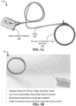
- FIGS. 1A and 1B show a diagram and an image of an exemplary acoustic orthopedic tracking system (OTS) 100, respectively.
- the acoustic OTS 100 includes an acoustic transducer array and supporting structure 110, also referred to as the "structure", configured to conform to a user's body, including an arm or leg extremity, head, neck, breast, torso or other body part, and used by the acoustic OTS 100 for acquiring acoustic imaging data, e.g., for producing an acoustic image, range-Doppler measurements, and/or feed into a therapeutic systems such as an orthopedic surgical system for affecting surgical operations.
- acoustic imaging data e.g., for producing an acoustic image, range-Doppler measurements, and/or feed into a therapeutic systems such as an orthopedic surgical system for affecting surgical operations.
- the acoustic OTS 100 includes a signal interface module 120 to provide an interface between the acoustic transducer array structure 110 and a signal generator and processing device 140 (shown in FIG. 1C ).
- the signal interface module 120 can include a signal processing circuitry and components to amplify, multiplex, convert analog-to-digital (A/D) and/or convert digital-to-analog (D/A), or otherwise condition the electrical signals to be transmitted by and received from the acoustic transducer elements of the array for signal transmission and reception with the signal generator and processing device 140.
- the signal generator and processing device 140 includes a transmit and receive electronics unit 142, and a data processing unit 144, as shown in the block diagram of FIG. 1C .
- Some examples of the transmit and receive electronics unit 142 (of the generator and processing device 140) of the present technology are described in International (PCT) Application Publication No. WO 2016/149427 .
- One example includes a synthetic aperture ultrasound/acoustic (SAU) system 100 shown in FIG. 1 of the above PCT Publication (reproduced as FIG. 1E in this document), in which the SAU system 100 includes a transmit/receive electronics module (TREM) 110E in electrical communication with an acoustic probe device 120E and with a data processing unit resident on the TREM 110E or an external computer device 130E.
- SAU synthetic aperture ultrasound/acoustic
- TREM transmit/receive electronics module
- the TREM 110E is configured to generate the individual coded waveforms on multiple channels transferred to the probe device for transmitting and receiving one or more composite waveforms (e.g., coherent, spread-spectrum, instantaneous-wideband, coded waveforms) based on the individual generated coded waveforms.
- the probe device can include the acoustic transducer array structure 110.
- the TREM 110E includes a waveform generator unit that includes a function generator and an arbitrary waveform generator (AWG).
- AMG arbitrary waveform generator
- the TREM 110E includes a system control unit to control the waveform generator unit for the synthesis of individual coded waveforms.
- the TREM includes signal conditioning and processing circuitry to amplify, select, and/or convert analog and digital signals, e.g., which can include analog/digital converters, multiplexers, amplifiers, etc.
- the TREM 110E includes a data processing unit (e.g., processor or microcontroller, and memory) is configured to transfer data with a central processing unit (CPU) of the computer 130E, e.g., such as executable instructions on waveform synthesis or probe control, and/or acquired or processed data.
- CPU central processing unit
- the acoustic OTS 100 includes a connector 130 (e.g., cable) in communication with the acoustic transducer array structure 110 and the signal interface module 120 to provide data communications (e.g., transfer the electrical signals) between the structure 110 and module 120.
- the connector 130 is strain relieved and includes attachable and detachable termini to be coupled to the structure 110 with one or more seals to prevent contaminants from intruding.
- the outer covering material of the connector 130 can be configured of autoclavable material to allow for sterilization.
- the connector 130 can be permanently attached to the structure 110, e.g., which may include the autoclavable material on the outer covering, or be configured of materials compatible with being disposed (e.g., for one-time use).
- FIG. 1C shows a block diagram of an example embodiment of a system of the present technology that may be implemented in conjunction with an external device or system 150, e.g., such as an orthopedic surgical system for surgical operations.
- the system includes the acoustic OTS 100 and the signal generator and processing device 140.
- the acoustic transducer array structure 110 is connected (e.g., via the signal interface module 120) to the transmit and receive electronics unit 142 of the signal generator and processing device 140, e.g., through a bidirectional analogic and/or digital signal lines.
- the transmit and receive electronics unit 142 can include circuitry and electronic components including, but not limited to, power amplifiers, RF amplifiers, variable gain amplifiers, diplexers, multiplexers, digital to analog converters, analog to digital converters, ASICs, FPGAs, DSPs, RF transformers, analog filters, digital filters, Ethernet circuitry, PCI circuitry, digital buffers, RAM, nonvolatile memory, communication components, and power supply electronics.
- the transmit and receive electronics unit 142 is in communication with a data processing unit 144 of the signal generator and processing device 140 to process and store data of the device 140.
- the data processing unit 144 may be resident on one or more computers (e.g., desktop computer, laptop computer, a network of computer devices in data communication with each other via the Internet (e.g., in the ⁇ cloud'), or other computing device including, but not limited to, a smartphone, tablet, or wearable computing/communications device).
- the data processing unit 144 may be resident in a device structure (e.g., housing) that includes the transmit and receive electronics unit 142.
- the transmit and receive electronics unit 142 is in communication with a data processing unit 144 via a digital interface, e.g., which may be any interface or collection of interfaces including but not limited to USB, FireWire, Ethernet, PCI, IEEE 1394 Serial, Wi-Fi, Fiber Channel, fiber optics, a wireless bus, a serial bus, or a parallel bus.
- a digital interface e.g., which may be any interface or collection of interfaces including but not limited to USB, FireWire, Ethernet, PCI, IEEE 1394 Serial, Wi-Fi, Fiber Channel, fiber optics, a wireless bus, a serial bus, or a parallel bus.
- the data processing unit 144 may include a programmable processing unit and storage device that may include, but is not limited to, the following components, e.g., one or more processors, serial processors, parallel processors, math co-processors, general purpose graphical processing units (GPUs), FPGAs, ASICSs, DSPs, nonvolatile memory, RAM, digital buffers, storage devices, hard drives, USB, FireWire, Ethernet, PCI, IEEE 1394 Serial, Wi-Fi, Fiber Channel, fiber optics, a wireless bus, a serial bus, external display adaptor, external display driver, a parallel bus, communications components, and power supply electronics.
- processors e.g., one or more processors, serial processors, parallel processors, math co-processors, general purpose graphical processing units (GPUs), FPGAs, ASICSs, DSPs, nonvolatile memory, RAM, digital buffers, storage devices, hard drives, USB, FireWire, Ethernet, PCI, IEEE 1394 Serial, Wi-Fi, Fiber Channel,
- the device 140 may also include a display device 148, e.g., such as a monitor, speaker, or other device to produce a combination of visual, audio or haptic output.
- a display device 148 e.g., such as a monitor, speaker, or other device to produce a combination of visual, audio or haptic output.
- the display device 148 may be incorporated together with the data processing unit 144 when the data processing unit 144 is resident on a computer, e.g., such as in a single unit or separately through cabling to an external display.
- the data processing unit 144 is configured to process the acquired acoustic data from the acoustic OTS 100 to produce a data set of the orthopedic structure (e.g., bone) or feature of the subject including biological and positional information, e.g., such as bone shape, density, location, orientation, and/or structural movement of features and the overall bone.
- the data processing unit 144 can provide the produced data set to the external device 150.
- the system produces the data set for providing the information in real-time to the external device 150 for a diagnostic or therapeutic application.
- FIG. 1D shows a block diagram of an example embodiment of the data processing unit 144.
- the data processing unit 144 include a processor 182 to process data and a memory 184 in communication with the processor 182 to store data.
- the processor 182 can include a central processing unit (CPU) or a microcontroller unit (MCU).
- the memory 184 can include processor-executable code, which when executed by the processor 182, configures the data processing unit 144 to perform various operations, such as receiving information, commands, and/or data, processing information and data, and transmitting or providing information/data to another entity (e.g., external device 150).
- the memory 184 can store other information and data, such as instructions, software, values, images, and other data processed or referenced by the processor 182.
- RAM Random Access Memory
- ROM Read Only Memory
- Flash Memory devices Flash Memory devices
- the memory 184 can store data and information of the data processing unit 144 and other units of the device 140.
- the memory 184 can store device unit parameters, and hardware constraints, as well as software parameters and programs for operation on the device 140.
- the data processing unit 144 includes an I/O unit 186 that can allow communicative connectability of the data processing unit 144 to other units of the device 140.
- I/O unit 186 can provide the data processing unit 144 to be in communications with other devices or systems, e.g., using various types of wired or wireless interfaces compatible with typical data communication standards, for example, including, but not limited to, Universal Serial Bus (USB), IEEE 1394 (FireWire), Bluetooth, IEEE 802.111, Wireless Local Area Network (WLAN), Wireless Personal Area Network (WPAN), Wireless Wide Area Network (WWAN), WiMAX, IEEE 802.16 (Worldwide Interoperability for Microwave Access (WiMAX)), 3G/4G/LTE cellular communication methods, and parallel interfaces.
- USB Universal Serial Bus
- IEEE 1394 WireWire
- Bluetooth IEEE 802.111
- WLAN Wireless Local Area Network
- WLAN Wireless Personal Area Network
- WWAN Wireless Wide Area Network
- WiMAX Worldwide Interoperability for Microwave Access
- WiMAX Worldwide Interoperability for Microwave Access
- the I/O unit 186 can also provide communicative connectability of the data processing unit 144 to an external interface (e.g., the external device 150), source of data storage, or display device (e.g., the display device 148).
- the I/O unit 182 of the data processing unit 144 can also interface with other external interfaces, sources of data storage, and/or visual or audio display devices, etc., to retrieve and transfer data and information that can be processed by the processor 182, stored in the memory 184, or exhibited on an output unit of the device 140 (e.g., display device 148).
- the system includes a position tracking device 146 to provide data to the data processing unit 144 used to determine the location coordinates, orientation, and other position and motion information of orthopedic structures of the body part with 6DoF.
- the data processing unit 144 is in communication with the position tracking device 146, e.g., which can be configured through a digital interface.
- the position tracking device 146 is operable to track the position of the acoustic transducer array structure 110 of the acoustic OTS 100, e.g., including the position data of individual array elements 111 disposed in the structure 110.
- the position tracking device 146 can measure the position of the acoustic transducer array structure 110 by employing a noncontact sensor of the device 146 to obtain data of the structure 110 and/or body part to which the structure 110 is attached.
- a noncontact sensor of the device 146 can include, but is not limited to, an optical sensor (e.g., video camera, CCD, LED, etc.), a magnetic sensor (e.g., magnetometer, Hall effect sensor, MEMs-based magnetic field sensor, etc.), rate sensor (e.g., gyro sensor, accelerometer, etc.), and/or electromagnetic, radio-frequency, and/or microwave sensors, or other detectors.
- the position tracking device 146 is configured to provide the data processing unit 144 with processed coordinate information or with the raw sensor data for the data processing unit 144 to process to produce the coordinate information of the structure 111 and/or body part.
- the data processing unit 144 is operable to process the coordinate information with the received acoustic echoes obtained from the acoustic OTS 100 to generate 6DoF coordinate estimates of the bone location, error estimates, acoustic images, and other relevant parameters of the orthopedic feature of the subject, e.g., with an update rate of 1 kHz or higher.
- the data-processed 6DoF bone coordinates, orientation and/or other information may be communicated by the data processing unit 144 of the device 140 to the external device 150 for use by the external device 150.
- the position tracking device 146 can include the Stryker Surgical Navigation System (SNS), e.g., such as the Stryker NAV3i Platform.
- the Stryker NAV3i Platform includes digital camera technology, positional data processing devices, and multiple visual display monitors for tracking in real time.
- the Stryker NAV3i Platform includes a navigation camera arm with one or more cameras (e.g., Built-in LiveCam) for imaging over a large range of motion, e.g., to accommodate various procedures and approaches.
- the data processing devices of the Stryker NAV3i Platform include an industrial computer (e.g., with high-end processing speed and RAM) and IO Tablet user interface with touch capability, e.g., with wireless integration (e.g., DICOM query/retrieve and DICOM client functionality for smooth integration into a hospital network) and various I/O outputs (e.g., HDMI, etc.) to other data processing devices, e.g., such as the data processing unit 144 of the device 140.
- industrial computer e.g., with high-end processing speed and RAM
- IO Tablet user interface with touch capability e.g., with wireless integration (e.g., DICOM query/retrieve and DICOM client functionality for smooth integration into a hospital network) and various I/O outputs (e.g., HDMI, etc.) to other data processing devices, e.g., such as the data processing unit 144 of the device 140.
- I/O outputs e.g., HDMI, etc.
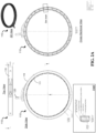
- FIG. 2A shows a schematic of an exemplary acoustic transducer array structure 110, showing top, side and cross-sectional views of the structure.
- the acoustic transducer array structure 110 includes an array of transducer elements and a housing body 119 to contain and position the transducer elements 111 for transmitting and receiving acoustic signals to/from a mass to which the acoustic transducer array structure 110 is applied.
- the housing body 119 includes a curved section where the transducer elements 111 of the acoustic transmit and/or receive transducer array are positioned, where the curved section of the housing body 119 can be configured to various sizes and/or curvatures tailored to a particular body region or part where the structure 110 is to be applied in acoustic imaging, measurement, or other implementations.
- the length, depth, and arc of the curved housing body 119 can be configured to make complete contact with a region of interest on an anatomical structure, e.g., such as a breast, arm, leg, neck, throat, knee joint, hip joint, ankle, waist, shoulder, or other anatomical structure of a human or animal (e.g., canine) subject to image or apply ultrasonic treatment to target volumes within such structures, such as splenic masses, cancerous or noncancerous tumors, legions, sprains, tears, bone outlines and other signs of damage or maladies.
- an anatomical structure e.g., such as a breast, arm, leg, neck, throat, knee joint, hip joint, ankle, waist, shoulder, or other anatomical structure of a human or animal (e.g., canine) subject to image or apply ultrasonic treatment to target volumes within such structures, such as splenic masses, cancerous or noncancerous tumors, legions, sprains, tears, bone outlines
- FIG. 2B shows a diagram of the acoustic transducer array structure 110 coupled to the acoustic coupler 112 to interface with a receiving body for acoustic signal transmission and reception.
- the acoustic coupler 112 is coupled to the transducer elements 111 of the acoustic transducer array structure 110 creating an acoustic signal transmission interface between the structure 110 and the receiving body (e.g., subject's body part).
- the transducer elements 111 are attached to the housing body 119 via a flexible bracket 118.
- the acoustic coupler 112 is able to conform directly onto the face of the transducer element 111, as illustrated in the diagram.
- the acoustic coupler 112 is attached to clip components of the flexible bracket 118 by an adhesive 113 on the external surface of the clips, e.g., to align in contact with the ⁇ tacky regions' of the hydrogel and/or outer lining of the acoustic coupler 112.
- the clips are configured to attach around the lip of the housing body 119 to provide direct contact between the acoustic coupler 112 and the face 111B of the transducer element 111.
- the transducer element 111 can include a transducer acoustic backing portion 111A that interfaces with electrical communication elements for transduction of electrical to/from acoustic energy.
- FIGS. 3A-3D show diagrams illustrating the exemplary acoustic OTS or multiple acoustic OTSes donned around a patient's leg to determine the topography of the bone, orientation of the bone in space, or other anatomical parameters of the patient's leg extremity.
- FIGS. 3A and 3B show various three dimensional views of the acoustic OTS 100 attached to the femur of a subject, which could be during a diagnostic and/or therapeutic procedure.
- FIG. 3C shows 3D view of a portion of the disclosed system employing two arrays of transducers per leg, including attaching two acoustic transducer array structures 110 on the leg: one for tracking the tibia and one for tracking the femur.
- FIG. 3D shows a 3D view of a break-out diagram depicting the example acoustic OTS 100 and the acoustic coupler 112 with respect to the subject.
- Example features of the disclosed system including the acoustic transducer array structure 110, the signal generator and processing device 140, and/or the position tracking device 146, are further described for various embodiments and implementations of the present technology.
- the acoustic transducer array structure 110 includes ultrasound transducers that are affixed to a frame or housing body 119 (shown in FIG. 2B , for example), and is configured to fully or partially surround a body part containing one or more bones.
- the structure 110 can be configured to be curved or approximately curved, for example, as in the shape of a circle or ellipsoid.
- the curved structure may be open, for example, to cover 120 or 270 degrees around the body part. The opening may provide utility for accessing specific regions of the body, for example, for accessing a hip bone.
- the structure 110 is circular and covers 360 degrees around the bone.
- the structure 110 may be flexible or semi-flexible but according to the invention it is rigid.
- the structure 110 conforms arbitrarily to the body part, for example, like a sleeve.
- Transducers attached to a flexible material enable this embodiment.
- the flexible materials may include, but are not limited to rubbers such as, latex rubber, nitrile rubber, neoprene rubber, silicone rubber, and combinations thereof. Flexible materials may also include polymers, plastics, and resins. Flexible circuits and flexible coaxial cables enable flexible electrical connections to the transducers.
- the structure 110 may contain hinges or pivot points between rigid sections that contain transducers, similar to chain links in a chain.
- the degrees of freedom provided by the semi-flexible design allow the structure 110 to conform to a variety of shapes.
- Position encoders located on each pivot point enable measurement of relative or absolute angle between adjacent sections.
- 6DoF refers to a Cartesian coordinate system with three dimensional spatial coordinates according to 3 orthogonal axes, e.g., commonly referred to x, y, and z axes, plus a rotation angle about each respective axis, commonly referred to as roll, pitch, and yaw, respectively.
- the structure 110 may be a fixed shape, such as a circular or elliptical ring or an approximately circular or elliptical polygon.
- the rigid embodiment of the structure 110 is structurally inflexible in all dimensions.
- the structure 110 supports ultrasound transducers such that the 6DoF position of all transducers are either a known, measured, or calibrated quantity relative to one or more designated points on the support structure.
- the 6DoF location of each transducer is measured dynamically with respect to one or more external spatial reference points.
- the distance from an external reference point to points on the transducers 111 or the housing body 119 of the structure 110 can be measured dynamically, for example, using one or more, but not limited to, optical imaging cameras (e.g., CCD), optical sensors (e.g., photodiodes), optical patterns (e.g., QR codes), light emitting diodes, fiber optics, quantum dots, florescent particles, magnetic sensors (e.g., magnetometers, Hall effect sensors, MEMS-based magnetic sensors, etc.), magnetic particles, magnets, electromagnets, magnetic nanoparticles, gold nanoparticles, MEMS sensors, capacitive sensors, electromagnetic sensors, microwave sensors, and combinations thereof.
- optical imaging cameras e.g., CCD
- optical sensors e.g., photodiodes
- optical patterns e.g., QR codes
- light emitting diodes fiber optics
- quantum dots e.g., quantum dots, florescent particles
- magnetic sensors e.g., magnetometers, Hall
- distances are measured to the structure from one or more common spatial reference points with known 6DoF coordinates.
- the 6DoF coordinates corresponding to each measurement point on the structure are triangulated from three or more distance measurements. For example, measurement uncertainties for each transducer or structure are approximately reduced in proportion to the square root of the total number independent measurements made per transducer or structure, if for example, each transducer has multiple sensors or measurement points in order to enable triangulation of the 6DoF coordinates.
- Coordinate transformations from one or more spatial reference points to one or more measurement points on the structure to each individual transducer are computed in real-time and stored for determining the position of the bone relative to one or more spatial reference points. The order of the coordinate transformations may follow several methods or formalisms to reach the same result, e.g., using direction cosines, Euler angles, or quaternions.
- the shape of the structure 110 may be optimized to accommodate specific body parts.
- the structure 110 may embody ergonomic shapes and sizes specific to various populations, e.g., females or males.
- the body part slips through the inner diameter region of the structure 110 up to the point where the bone will be tracked.
- an acoustic transducer array structure to measure the tibia slips over the foot, ankle, past the calf muscle to a region approximately 3-6 inches below the knee joint.
- the structure may be sized to accommodate specific size ranges of certain body parts, for example (e.g., calf muscles ranging from 6 to 10 inches in diameter).
- the structure 110 may be fabricated from a variety of materials, e.g., including but not limited to combinations or composites of aluminum, titanium, stainless steel, polymers, fiberglass, plastics, rubbers, glass, or resins.
- the structure 110 is designed to move with the body part as the body part is moved. For example, when the structure 110 is positioned around the thigh and hamstring region containing a femur bone, and as the leg is manipulated, the structure 110 is able to move with the leg such that angular excursions will not cause a detrimental effect on the acoustic data acquisition.
- the structure 110 can be configured to be of lightweight in order to minimize mechanical momentum as the body part containing the bone is moved.
- the structure 110 has freedom of motion with respect to the bone contained within the body part.
- the range of motion of the structure 110 with respect to the bone may be limited by the method of attachment of the structure 110 to the body part.
- the structure 110 is taped to the body part, the structure 110 approximately follows the body part as it is moved, but the flexibility in the tape and flexibility of the skin and underlying soft tissue allows for motion of the structure 110, although limited motion.
- the structure 110 is designed to have at least a limited freedom of motion with respect to the bone (contained within the body part), but the structure 110 is not rigidly coupled to the motion of the body part or bone contained within the body part.
- the time dependent 6DoF coordinates of the bone can be estimated relative to the structure 110, and the 6DoF coordinates of the structure 110 transform the 6DoF coordinates of the bone to a fixed point in space at each instant in time.
- Such operations can be implemented, which are in contrast to obtaining through static or time-independent transformations applied to the time dependent 6DoF coordinates of the structure 110.
- the motion of the structure 110 relative to the bone can be operated such that such motions are limited, e.g., to prevent the structure 110 from detaching from of the body part.
- the structure 110 may be attached to a body part in a specific region where the bone contains features that are more easily tracked compared to another region.
- the non-rigid coupling of the structure 110 relative to the bone has advantages over other means of rigid coupling. Most importantly, for example, the coupling is non-invasive. Also, for example, the non-rigid coupling of the structure 110 does not require methods associated with surgery, such as incisions, drilling, injections, metal screws, metal rods, temporary implants, permanent implants, and sutures. Non-rigid coupling of the structure 110 also protects the body from damage, e.g., such as bruising, infections, bleeding, blood clots, contusions, and scar tissue.
- the non-rigid coupling of the structure 110 is also naturally ergonomic and is configured to automatically find the lowest mechanical stress to both the structure 110 and the body part to which it is to be attached, where a mechanical system referred to here includes the structure 110, the acoustic coupler 112, the body part, the bone, and the component of the structure 110 used to affix the structure 110 to the body part and allow limited movement.
- a mechanical system referred to here includes the structure 110, the acoustic coupler 112, the body part, the bone, and the component of the structure 110 used to affix the structure 110 to the body part and allow limited movement.
- coupling acoustic energy from the structure 110 into an irregularly-shaped body part uses an acoustic coupling material, for example, such as a hydrogel that is flexible, elastic, and deformable.
- the structure 110 may be cylindrical, with a variable or fixed height so as to accommodate different body parts and for affixing the structure 110 containing the transducer to the body part.
- the structure 110 may be temporarily affixed to the body part.
- the acoustic transducer array structure 110 can include a securement component to affix the structure 110 to the body part, in which the securement component can include, but is not limited to, tape, adhesives, straps, buckles, snaps, buttons, Velcro, and cuffs, and combinations thereof.
- Flexible cylindrical extensions from a circular ring structure may be used to hold the structure 110 to the body part.
- the inner diameter of the cuffs may be slightly smaller than the circumference of the body part so as to slip over the body part and hold it firmly around the entire circumference.
- the rubber cuff may form a seal around the entire body part so that the void between the patient and the structure containing the transducers may be filled with a liquid or semi-liquid acoustic coupling medium.
- the cuff may be made from pure or composite elastic materials, including, but not limited to rubber elastomers, silicone, polyurethane, latex, neoprene, natural rubber, fabrics, nylon, silk, or cotton. Said cuff may be autoclavable for reuse or disposable for one use only. Materials compatible with autoclaving and chemical sterilization are well known in the field of medical devices.
- the acoustic coupling medium 112 of the disclosed technology may include several materials, e.g., including, but not limited to water, polymers, organic solvents, organic chemical compounds, inorganic chemical compounds, and combinations thereof.
- the acoustic coupling medium 112 may specifically contain water, acrylamide, bisacrylamide, PVA, PVP, DMSO, propylene glycol, sodium benzoate, sodium alginate, sodium borate, sodium chloride, ammonia persulfate, calcium sulfate, magnesium sulfate, tetramethylethylenediamine (TMED), chitosan, acetic acid, ethanol, polyethylene glycol, sorbitol, dextrose, and aloe vera, and combinations thereof.
- the acoustic coupling medium 112 may contain organic or inorganic chemical compounds or particles to render it bacteriostatic.
- the acoustic coupling medium 112 may be liquid or a gel with a sound speed and acoustic impedance similar to that of soft tissue.
- the sound speed provided by the acoustic coupling medium 112 ranges from 1450 to 1590 m/s to accommodate soft tissues, e.g., ranging from fat to muscle, respectively.
- the acoustic impedance ranges from 1.3 to 1.7 MRayl (kg/(sec ⁇ m 2 ) ⁇ 10 6 ) to accommodate soft tissues ranging from fat to muscle, respectively.
- the acoustic coupling medium 112 may include a pre-formed gel material, for example, a cylinder of hydrogel.
- the hydrogel may primarily include PVA and water subjected to several freeze thaw temperature cycles in order to crosslink the polymer and form a gel.
- the PVA solution Prior to temperature cycling, the PVA solution is poured into a mold.
- the shape of the exemplary hydrogel acoustic coupling medium 112 may be tailored to individual body parts and specific transducer structures.
- the tibia presents a variable thickness of soft tissue around the leg where the tissue is thin at the shin and thick at the calf.
- a variable-thickness cylindrical hydrogel pad may be formed to provide a variable standoff path around the tibia so as to be thick at the shin and thin at the calf in order to place the acoustic focal region at the bone surface.
- Three-dimensional tomographic imaging information may be utilized to ergonomically tailor a gel pad to each patient.
- the hydrogel adheres to the skin such that it may be removed with force, but not enough force to injure the skin or cause discomfort.
- the hydrogel has sufficient water and ionic content to keep the skin hydrated and flexible for long periods of time so as to minimize discomfort and acoustic artifacts at the gel-skin interface.
- the hydrogel has a groove or slot that accepts the ultrasound transducers and supporting structure with acoustic gel applied to the transducers.
- the structure is affixed to the body part by aforementioned temporary securement component.
- the acoustic transducer array structure is an integrated device including ultrasound transducers and a rigid supporting structure or frame and is enclosed in a casing portion that protects the electronics and transducer elements from mechanical damage.
- An acoustically compatible polyurethane or similar material may be employed as the outermost coating and to seal the enclosure up to where the cabling enters the device.
- the thickness, acoustic impedance, attenuation, and sound speed of the polyurethane coating on the transducers is controlled to optimize sound transmission as part of one or more acoustic matching layers present on each transducer.
- the connector 120 (e.g., cabling) can be configured to be strain relieved and captured into the device with one or more seals to prevent contaminants from intruding.
- the entire acoustic transducer array 110 up to the cabling may be autoclaved or chemically sterilized to allow for its reuse on multiple patients. Materials compatible with autoclaving and chemical sterilization are well known in the field of medical devices.
- the transducers 111 convert electrical energy to acoustic pressure waves and acoustic pressure waves into electrical energy.
- piezoelectric materials may be used in the transducers 111, and are efficient electroacoustic transducers, e.g., including, but not limited to lead zirconate titanate (PZT), lead zinc niobate and lead titanate (PZN-PT), lead magnesium niobate and lead titanate (PMN-PT), lithium niobate, barium titanate, and lead metaniobate.
- PZT lead zirconate titanate
- PZN-PT lead zinc niobate and lead titanate
- PMN-PT lead magnesium niobate and lead titanate
- lithium niobate barium titanate
- lead metaniobate lead metaniobate.
- PVDF polymer polyvinylidene fluoride
- piezoelectric materials are formed as ceramics with a prescribed grain size, e.g., containing small crystals of the specific materials (e.g., PZT) that are sintered together.
- Other piezoelectric materials are formed from a single crystal of a piezoelectric material (e.g., PZN-PT, PMN-PT, etc.).
- the transducers may be formed from one or more composites of the aforementioned materials combined with materials known to absorb or dampen acoustic energy (e.g., polyurethane, epoxy, etc.).
- Such composites may be formed by dicing and sub-dicing the transducers elements with cuts of various widths, lengths, and depths, which are filled with one or more attenuating materials, in order to isolate and/or attenuate specific vibrational modes.
- Transducers may be fabricated in multiple layers or stacks in order to increase bandwidth and efficiency.
- each transducer 111 includes a circular element with a resonant frequency ranging from 1 to 10 MHz, and a -6 dB, half-amplitude fractional bandwidth ranging from 10 to 120% of the resonant frequency.
- the circular elements have a fixed focal depth and produce an acoustic beam with radial symmetry about the central axis perpendicular to the plane of the circular element.
- the circular elements have a preferred combination of center frequency of transmission, element diameter, and geometric focal depth, such that the range over which the acoustic field is focused, also known as the depth-of-focus or depth-of-field, includes the tissue-bone interface.
- the focal depth also known as the Fresnel distance, and depth-of-focus also limit the center frequency and bandwidth due to expected frequency and depth-dependent attenuation, which may range from about 0.2 to over 1 dB/cm/MHz.
- a bone located in shallow tissue is ideally located using a high center frequency such as 8 MHz, compared to a bone located deeply in tissue, which may be ideally located using a 2 MHz center frequency.
- the attenuation at the maximum expected depth of the bone is not greater than 60 dB so as to accommodate a reasonable receiver gain.
- the circular elements are preferably matched to the impedance of the acoustic coupling medium 112 with one or more matching layers in order to maximize power transmission.
- the circular elements may be geometrically focused by either forming them into a concave shape or with the addition of a lens with a sound speed less than or greater than the acoustic coupling medium 112.
- the purpose of lowering the side lobes of the spatial response of the circular element to below the standard first side lobe level of -17.5 dB it is preferable, but not necessary, to include an apodization property to the acoustic lens or within one or more matching layers so as to reduce the side lobe level.
- the apodization is accomplished by including a material that has a variable attenuation as function of radius across the circular area of the transducer. Variable attenuation is accomplished by incorporating acoustic absorbing material with varying amounts as a function of radius.
- Such materials include, but are not limited to, micron-sized air bubbles, micron-sized microballoons of air, micron-sized particles of, but not limited to, rubber, plastic, glass, metal, and ceramic.
- the number of circular transducer elements arranged on a circular ring structure is at least 16 (e.g., and in some embodiments, 32 or greater), as the standard error in determining the position of the bone is proportional to the square root of the number of independent measurements - thus 0.25 times the standard error for 16 elements and 0.125 times the standard error for 64 elements.
- the number of elements is largely dictated by the element diameters, as dictated by several relevant design parameters as discussed previously, and the circumference of the inner lumen of the ring. Using equations for circular ultrasonic transducer design, trade studies can be formulated to explore element diameters and center frequencies that can be used for a particular set of constraints.
- the approximate element diameters and center frequency combinations that satisfy the aforementioned design constraints include, but are not limited to, 6 mm diameter at 8 MHz, 6-7 mm diameter at 7 MHz, 7 mm diameter at 6 MHz, 5 mm diameter at 5 MHz, 8-9 mm diameter at 4 MHz, 10-11 mm diameter at 3 MHz, 12-13 mm diameter at 2 MHz, 16-19 mm diameter at 1 MHz.
- FIG. 4 shows a diagram illustrating an example of the trade study.
- the goal of the bone tracking approach is to maximize the potential for specular reflection from the bone and minimize the potential for Rayleigh scattering or Rayleigh-like scattering from within the bone itself.
- the acoustic transmission coefficient for bone is greater than zero, and may be approximately 0.5, a substantial amount of acoustic energy enters the bone and can be scattered throughout the structure.
- bone is a living tissue, albeit with much greater sound speed and acoustic impedance compared to soft tissue, scattering from within the bone is similar to Rayleigh scattering in soft tissue; however, bone has much greater frequency and depth-dependent attenuation ranging from 4-8 dB/cm/MHz.
- higher center frequencies are preferred to minimize the potential for Rayleigh scattering from within the bone.
- the potential for specular scattering is maximized for larger beam diameters, which cover a larger area over the bone surface, which increases the possibility of finding a flat or approximately flat region from which a specular reflection is received.
- the -6 dB beam diameter is approximately given by the f-number of the aperture times the wavelength, where f-number is approximately given by the Rayleigh distance or focal depth divided by the element diameter.
- the aforementioned transducer diameter and center frequency combinations have beam widths ranging from approximately 4-4.7 mm for the 1 MHz designs to approximately 1.6 mm for the 8 MHz design.
- a preferable design based on aforementioned constraints would fall somewhere between the extremes, for example, a 5 mm diameter element at 5 MHz with a beam diameter of approximately 1.9 mm.
- the transducer elements 111 and configuration of the elements 111 are not limited to a single ring element placement within a single plane.
- the elements may be placed along two or more rings such that the elements occupy two or more planes in a cylindrical arrangement, e.g., so as to track bone echoes along two or more planes along the length of a femur.
- the individual rings of elements occupying each plane may also be staggered with respect to the neighboring ring so as to distribute spatial samples more uniformly around the bone, for example, in a helical pattern or helical-like pattern such as a spiral.
- the elements may be placed to achieve a periodic spatial sampling such that the angle between the elements is constant, for example, with 11.25 degrees separating 32 elements to span a full 360 degrees around the bone.
- a constant sampling arrangement would be applicable to tracking a femur bone, which is roughly circular.
- Applications where the optimal spatial sampling of the transducers is aperiodic or non-uniform or spatially diverse in three dimensions may be envisioned for tracking specific bones such as the hip bone, which does not conform to a circular geometry.
- the transducer elements 111 are arranged in the same plane with each other such that all are pointing at the same point in space. In other embodiments, for example, the transducer elements 111 are fixed to point at angles determined to maximize specular reflections in the acoustic echoes from a particular bone.
- the cross-section of the tibia is not round, but rather, approximately triangular. Transducer elements may be arranged to point along 3D vectors required to maximize the specular reflection from the surface of the tibia.
- the location of the bone is maintained within the depth-of-focus with use of an acoustic coupling medium, e.g., a hydrogel.
- the elastic hydrogel coupling medium 112 may conform to irregularities in the body part and soft tissue surrounding the bone.
- the example hydrogel coupling medium 112 may be ergonomically designed and molded to fit a particular application.
- Arrays may include hundreds or thousands of elements arranged in a circular or ellipsoidal or curved aperture that is either open or closed. For example, instead of using a single element to focus an acoustic beam, focusing may be achieved using suitably delayed transmissions from several small transducers elements arranged in one or more 1D, 1.25D, 1.5D, 1.75D, 2D, or 3D linear or phased arrays, as consistent with the current state-of-the-art in clinical ultrasound scanners.
- Linear arrays typically have a pitch or spacing between element centers of one wavelength or more, and phased arrays have a pitch of less than one wavelength, and preferably one-half wavelength or less to allow for steering the acoustic beam.
- the operating of linear or phased arrays can be either in full or partially synthetic aperture mode as commonly implemented in clinical ultrasound scanners.
- the disclosed system is not limited to a specific means or aperture dimension for transmitting or receiving acoustic energy.
- the disclosed system is not limited to a particular diameter, shape, or size for the transducer array.
- the disclosed system is directly applicable to partially or fully beamformed ultrasound images from one or more aspects or views or angles or directions, tomographic ultrasound over angles ranging from 0 to 360 degrees, synthetic aperture ultrasound, and three dimensional ultrasounds data sets.
- Specific embodiments utilizing an array or plurality of arrays of transducer elements apply specifically to high resolution and high speed orthopedic tracking with circumferential or tomographic coverage of a bone, e.g., a femur.
- a 1D array of transducer elements with pitch ranging from 1 ⁇ 2 wavelength to several wavelengths are arranged in a full circle to form a tomographic array .
- FIG. 5A shows a top view example of such a tomographic array.
- the target application of the array dictates the required spatial sampling around the circumference of the array. For example, in some cases it may be beneficial to utilize large elements with a narrow directivity so as to focus acoustic energy both on transmission and reception along specific directions or radial vectors defined by the vectors pointing from the center of the element to the geometric center of the circular array. In other cases, for example, it may be beneficial to utilize small elements with a wide directivity such that the array may operate with, for example, dynamic focusing and apodization on both transmission and reception.
- an example array can contain 1024 transducer elements arranged side-by-side with azimuthal pitch ranging from 1 ⁇ 2 wavelength to 2 wavelengths that comprise a tomographic aperture with radius equal to approximately 1024 times the element pitch divided by 2 ⁇ .
- FIG 5B shows a top view examples of such an array
- FIGS. 5C and 5D show a side view and an isometric view of such an array. Accordingly, element widths range from 1 ⁇ 2 wavelength to 2 wavelengths minus the space between elements, i.e., the kerf.
- Element heights in the elevation dimension may span several wavelengths in order to provide both passive and geometric focusing ability in elevation, depending on the typical depth and depth-of-focus requirement for a particular application.
- the described tomographic aperture is provided for the purpose of illustrating specific transmission and reception patterns.
- the transmission and reception patterns are equally applicable to arrays that contain arbitrary element sizes and numbers of elements arranged in a tomographic configuration.
- transmission is enabled on one or more transducer elements, preferably, in the case of more than one element, a contiguous group of elements, with electronic delays assigned to each to form a single focused acoustic beam, i.e., a real beam.
- FIG. 5E illustrates an example of such a configuration in which transmission is enabled on a contiguous group of elements.
- the case of transmission on one element is handled separately as further described below.
- the process of beam formation is well known in the art of ultrasound imaging, radar imaging, and signal processing.
- the real transmit beam may result from transmission on 64 contiguous elements, e.g., elements 1 through 64, where the focal point of the beam falls somewhere within the sector subtended by the arc length and angle spanned by elements 1 through 64, as depicted in the exemplary diagram of FIG. 5F .
- transmission on elements 1 through 64 can be followed by transmission on elements 2 through 65, as shown in the exemplary diagram of FIG. 5G .
- the transmit beam may step arbitrary increments in element index, for example, transmission on elements 1 through 64 followed by transmission on elements 257 through 320.
- the real transmit beam may be steered arbitrarily in space by applying suitable delays to each participating transmit element.
- stationarily e.g., 1 1 1
- incrementally e.g., 1 2 3
- sequentially e.g., 1 3 5
- periodically e.g., 1 513 1 513
- randomly e.g., 254 46 884 3
- the real transmit beam is fired according to a sequence that repeats periodically with a defined cycle time.
- the receive aperture includes one or more elements centered or approximately centered with the transmit aperture, as depicted in FIG. 5H .
- the receive aperture follows the transmit aperture as it changes location between transmissions.
- Parameters affecting the real beam may be pre-determined according to a priori information, e.g., an MRI or CT image that gives measurements of distance from the expected location of the transducer elements to the surface of the bone.
- a priori information e.g., an MRI or CT image that gives measurements of distance from the expected location of the transducer elements to the surface of the bone.
- the a priori information may be used in determining the location of the beam relative to features on the bone, e.g., normal to a flat region or normal to the local apex of a curved region.
- an optimization process can determine the number of elements involved in a transmission, the transmission delays for each element, the transmission amplitudes for each element (e.g., a normalized per-element transmit apodization ranging from 0 to 1).
- the real beam may be manually or automatically tuned to place the focal point at the surface of a bone according to focusing metrics derived from coherently beamforming echoes received from the vicinity of the bone, e.g., echo intensity, echo power and image contrast in the vicinity of the bone.
- transducer elements utilized for reception may also be optimized to determine the optimal number of elements involved in reception, the received delays for each element, and the weightings of each received echo (e.g., a normalized per-element receive apodization ranging from 0 to 1).
- the f-number e.g., the focal depth divided by the aperture size of the transmit and receive aperture is held approximately constant for each beam relative to the focal point aligned with the surface of the bone for a plurality of points insonified on the bone.
- the aperture sizes must be approximately 1 cm and 3 cm, respectively. This can be seen with from the example diagram in FIG. 5I , where f-number of 1 is maintained for two focal points that are at 1 cm and 3 cm, respectively, from the transmit/receive apertures on two sides of the array.
- aperture size is defined by the linear distance measured to points on the most distant elements comprising the aperture, e.g., the chord length.
- synthetic aperture beamforming may be employed.
- synthetic aperture embodiments many possibilities exist for beam formation.
- a synthetic transmit aperture may utilized with a non-synthetic receive aperture.
- a non-synthetic transmit aperture may be used with a synthetic receive aperture.
- a synthetic transmit aperture may be used with a synthetic receive aperture.
- transmission from the previously described example array is enabled on one transducer element at a time, e.g., in a synthetic transmit aperture format, followed by reception on one or more elements simultaneously that include the transmit element and elements to either side of the transmit element.
- This embodiment differs from the above described embodiment in that one transmit element is utilized instead of a group of transmit elements.
- transmission on element 1 is followed by reception on a contiguous group of 64 elements ranging from 993 to 32.
- transmission on element 2 is followed by reception on 64 elements ranging from 994 to 33.
- transmission on element 3 is followed by reception on 64 elements ranging from 995 to 34. This pattern is continued sequentially until all elements are used for transmission one time to complete a single cycle.
- this embodiment also applies to smaller or larger receive apertures (e.g., 32 or 128 elements), where the transmit element is approximately centered within the receive aperture, and the receive aperture steps with the transmit element.
- a special case of synthetic aperture is implemented for transmission on one element and reception on the same element.
- This embodiment differs from the above described embodiment in that one transmit element is utilized instead of a group of transmit elements.
- transmission and reception may proceed out of sequential order, for example, in sequential quadrants.
- the cycle may start with transmission on element 1 followed by reception on element 1.
- transmission on element 257 is followed by reception on element 257.
- transmission on element 513 is followed by reception on elements 513.
- transmission on element 769 is followed by reception on element 769.
- transmission on element 2 is followed by reception on elements 2.
- transmission on element 258 is followed by reception on elements 258.
- transmission on element 514 is followed by reception on elements 514.
- transmission on element 770 is followed by reception on elements 770.
- the pattern continues by increasing the element index for transmission and reception by one.
- the pattern ends with transmission on element 1024 followed by reception on element 1024. Each iteration is incremented by one element until all elements are used for transmission once to complete one cycle before it is repeated.
- transmission and reception may proceed out of sequential order in other divided manners, including, but not limited to sequentially in haves, quadrants and octants.
- transmission may proceed according to a random or pseudorandom permutation of the elements, e.g., 328; 82; 119; 829; 130; 91; 848; 485; 4; 238 and so forth until all elements are used for transmission one time to complete a transmission cycle.
- reception occurs on the transmit element. For example, after transmission on element 328, a reception occurs on element 328.
- An important feature of this embodiment is that only 1 transmit channel and 1 receiver channel is required per transmission event, thus dramatically reducing the hardware complexity and volume of data for this operating mode compared to full synthetic aperture modes that utilize many more elements on reception.
- a reduced data rate in turn reduces the time required to transfer echo samples and the time required to process the samples, and ultimately, reduces the time lag between the true physical location of a target, e.g., a bone, and the estimated location of the target.
- a high rate of position feedback with low lag is of critical importance in assisted surgery in order to prevent controller feedback errors due to inaccuracies, undersampling, and hysteresis.
- a second special case of synthetic aperture is implemented for transmission on one element and reception on two elements, specifically, reception on the transmit element and on one immediately adjacent element.
- transmission on element 1 is followed by reception on elements 1 and 2.
- transmission on element 2 is followed by reception on elements 2 and 3.
- transmission on element 3 is followed by reception on elements 3 and 4.
- the pattern ends with transmission on element 1024 and reception on elements 1024 and 1 to complete one cycle, after which it is repeated.
- the cycle may start with transmission one element 1 followed by reception on elements 1024 and 1.
- transmission and reception may proceed out of sequential order, for example, in sequential quadrants with transmission on element 1 followed by reception on elements 1 and 2.
- transmission on element 257 is followed by reception on elements 257 and 258.
- transmission on element 513 is followed by reception on elements 513 and 514.
- transmission on element 769 is followed by reception on elements 769 and 770.
- transmission on element 2 is followed by reception on elements 2 and 3.
- transmission on element 258 is followed by reception on elements 258 and 259.
- transmission on element 514 is followed by reception on elements 514 and 515.
- transmission on element 770 is followed by reception on elements 770 and 771. Each iteration in incremented by one element until all elements are used for transmission once to complete one cycle before it is repeated.
- transmission and reception may proceed out of sequential order in other divided manners, including, but not limited sequentially in haves, quadrants and octants.
- transmission may proceed according to a random or pseudorandom permutation of the elements, e.g., 72; 987; 63; 231; 546; 771; 9; 1021; 393; 20 and so forth until all elements are used for transmission one time to complete a transmission cycle.
- reception occurs on the transmit element, and on the preceding element or on the following element, e.g., for transmission on element 72, a reception occurs on elements 71 and 72 or on elements 72 and 73. Simultaneous reception on elements 71, 72 and 73 is also possible; however, the information contained in echoes recorded for elements 71 and 73 are largely redundant.
- An important feature of this embodiment is that only 1 transmit channel and 2 receiver channels are required per transmission event, thus dramatically reducing the hardware complexity and volume of data required for this operating mode compared to full synthetic aperture modes that utilize many more elements on reception.
- a reduced data rate in turn reduces the time required to transfer echo samples and the time required to process the samples, and ultimately, reduces the time lag between the true physical location of a target, e.g., a bone, and the estimated location of the target.
- a high rate of position feedback with low lag is of critical importance in assisted surgery in order to prevent controller feedback errors due to inaccuracies, undersampling, and hysteresis.
- a range window of 3 cm is first insonified by a transmission on aperture 1 followed by a coherent transmission on aperture 2 after a prescribed delay, e.g., 20 microseconds or 3.08 cm in space at sound speed equal 1540 m/s, followed by reception on aperture 1, followed by reception on aperture 2.
- FIG. 5K illustrates an example sequence of transmit and receive signals as a function of time.
- a high speed multiplexer may be used to switch reception from apertures 1 and 2. Using this technique, the resulting cycle time required to cover all elements on transmission is divided by approximately a factor of 2. Likewise, additional reductions in cycle time are allowed for each additional staggered transmission. For example, 3 staggered transmissions reduces the cycle time by approximately a factor of 3. As an alternative to multiplexing, additional receive channels may be utilized.
- the transmission delays utilized to stagger transmissions may be varied randomly in order to temporally decorrelate coherent echoes from previous transmissions, thus producing what is sometimes referred to as temporal dithering in fields such as ultrawideband communications.
- simultaneous transmissions are enabled using coded waveforms, specifically, waveforms that are orthogonal, e.g., their mutual cross correlations are zero or approximately zero for all delays.
- simultaneous transmissions are enabled using coded waveforms, specifically, waveforms that are partially orthogonal, e.g., their mutual cross correlations are zero or approximately zero for a range of delays.
- one or more receptions occur on array elements that are between 90 degrees and -90 degrees away from the phase center of the transmitting aperture, e.g., in a pitch-catch transmit-receive fashion, for the purpose of measuring the time of flight and attenuation for a given propagation path.
- array elements that are between 90 degrees and -90 degrees away from the phase center of the transmitting aperture, e.g., in a pitch-catch transmit-receive fashion, for the purpose of measuring the time of flight and attenuation for a given propagation path.
- FIG. 5L using the above described example array, for a transmission on element 1, there are one or more receptions on elements 257 through 769.
- a complete cycle of such transmissions and receptions comprises a transmission tomographic dataset from which sound speed and attenuation may be estimated and used for refining beamformer delays on both transmission and reception.
- the disclosed technology includes methods for processing the data, e.g., using the data processing unit 144 (shown in FIG. 1C ), to produce a data set identifying shape, location, and movement information of an orthopedic structure of a body part from which the acoustic signal data is acquired.
- Example features of the disclosed method are further described for various embodiments and implementations of the present technology.
- Acoustic (e.g., ultrasound) pulses are transmitted from the plurality of acoustic transducer elements 111 of the structure 110, e.g., including sequentially one-at-a-time, simultaneously, or in a time-staggered or time-delayed pattern.
- Each transmission is accompanied by receptions of acoustic echoes on one or more of the transducer elements 111 corresponding to a single transmission.
- the echoes are received only on the same transducer.
- reception occurs on one or more transducers simultaneously.
- the received echoes are amplified, filtered, and temporally sampled sufficiently, e.g., by the device 140, to retain all relevant spectral information corresponding to the echoes from soft tissue and bone as is dictated by the Nyquist sampling theorem.
- Received echoes are digitally sampled and stored for processing.
- the transmitted pulse contains the widest bandwidth possible, e.g., around 100% fractional bandwidth, which approximately corresponds to an impulse response of a single acoustic cycle.
- the reason for the high bandwidth being that the location of specular echoes from the bone will have a range uncertainly that is approximately inversely proportional to wavelength divided by fractional bandwidth.
- an 80% fractional bandwidth system operating at 5 MHz has a wavelength of 0.308 mm.
- the range measurement uncertainty for this example pulse is approximately 0.308 mm divided by 0.8, which equals 0.385 mm.
- Other sources of measurement uncertainty may include, but are not limited to, spatial averaging caused by the finite beam size, electronic noise, temporal sampling, quantization noise, side lobes, grating lobes, attenuation, sound speed, and motion. Except in the case of very high velocities of motion of the array or patient, greater than 1 m/s, the bandwidth, wavelength, and sound speed are typically the largest sources of measurement uncertainty.
- transmitted waveforms with a large time-bandwidth (e.g., spread-spectrum waveforms) product enable deeper penetration at a higher transmitted frequency in order to compensate for loss in signal-to-noise ratio (SNR) due to frequency and depth-dependent attenuation.
- SNR signal-to-noise ratio
- the waveforms used belong to a class of waveforms known as spread-spectrum waveforms.
- Such waveforms are robust to deleterious factors including, but not limited to, frequency and depth-dependent attenuation, electronic noise, cross-talk between adjacent channels, and acoustic reverberation.
- waveforms can be transmitted with a pulse-repetition-frequency (PRF) ranging arbitrarily up to about 100 kHz, with the upper end dictated by the sound speed, attenuation, the maximum depth from which the echoes contain useful information, degree of spatial and temporal overlap between neighboring transmitted beams (e.g., staggered transmissions), speed of transmit and receive multiplexer circuitry, electronic crosstalk, and potential tissue heating.
- PRF pulse-repetition-frequency
- the PRF and the number of transmissions per cycle to adequately insonify independent locations on the bone dictate the rate at which the OTS provides position feedback on the 6DoF coordinates of the bone.
- FIG. 6A The specular echo signature from a human femur bone suspended in water is shown in FIG. 6A , in which these example results were measured and processed in example implementations of the disclosed system.
- echoes were recorded using a Philips L7-4 linear array operating at 5 MHz and approximately 80% FBW. The transmission occurred on a single element and echoes were received on the same element. Except for lensing in elevation, there was no focusing in azimuth. Echoes were recorded every 0.5 degree around the circumference of the bone.
- FIGS. 7A and 7B show example radial patterns for a human femur
- FIG. 7C shows an example radial pattern for a human tibia, e.g., as obtained from CT volumes of both bones.
- the radii measured to the centroid of the cross-sectional slice through bone along its length was quantified for 64 angles spanning 360 degrees.
- the corresponding circumference (denoted perimeter in the original figures internally) of the bones as a function of length were quantified, as shown in FIG. 7D for the femur and FIG. 7E for the tibia. It was observed that some regions have more rapidly changing circumference than others, particularly close to the knee j oint. It is in these regions that the cross-sectional patterns are the most sensitive and feature rich for bone tracking.
- the pattern may be matched to a library of patterns determined from any means of tomographically imaging the bone, for example, as determined from a high resolution computed tomography (CT) image of the bone.
- CT computed tomography
- the disclosed method includes a process for matching the specular acoustic echo pattern from bone sampled at one or more points on the bone to a library of patterns sampled according to the array geometry, e.g., in which the process can employ matching the pattern in order to match the topography of the bone, and thus, estimate the orientation of the bone in 6DoF coordinate space according to the location of the transducers relative to a fixed point in space.
- the method is not "speckle tracking", as ultrasound speckle is due to random scattering, which is tracked using correlation between ultrasound images. "Specular” and “speckle” refer to different echo properties.
- Signal processing is applied to the amplitude and phase information present in the received radio-frequency (RF) echoes to determine a pattern match against patterns automatically generated from a three dimensional library containing rigid bone information.
- Pattern matching can be achieved by statistically correlating information in the echo samples to patterns generated from the library. Penalty terms can be placed on each pattern sample to make the pattern matching robust to variable sound speed.
- Information about tissue types between the transducer and the bone surface can be used to inform the pattern matching algorithm for a more precise match, for example, sound speed information obtained from ultrasound tomography or inferred from MRI relaxation time information or CT Hounsfield unit information.
- Example algorithms may include, but are not limited to, linear cross correlation, circular cross correlation, sum-absolute-difference (SAD), linear regression, non-linear regression, first order statistics, second order statistics, higher-order statistics, Fourier transform, Mellin transform, Fourier-Mellin transform, Radon transform, Hankel transform, Eigenvalue decomposition, radial symmetry transform, singular value decomposition, pseudoinverse (e.g., generalized inverse, Moore-Penrose inverse, etc.), matrix inverse, pivot transformations, orthogonal transformations, wavelets, wavelet transform, matched filters, Hilbert transform, FIR filters, IIR filters, nonlinear filters, interpolators, and combinations thereof.
- the algorithms may operate on the amplitude, phase, or both amplitude and phase information contained within the echoes.
- the inputs to the algorithm include, but are not limited to, a library of three dimensional information about the bone being tracked that is searchable through geometric projections (e.g., ray tracing), 6DoF coordinate information about the transducer locations, a priori information about the sound speed of the coupling medium and expected sound speed through soft tissue, timing information about the acoustic echoes, amplitude scaling information about the acoustic echoes, and transmitted waveform information corresponding to each acoustic echo.
- geometric projections e.g., ray tracing
- 6DoF coordinate information about the transducer locations e.g., 6DoF coordinate information about the transducer locations
- a priori information about the sound speed of the coupling medium and expected sound speed through soft tissue e.g., ray tracing
- 6DoF coordinate information about the transducer locations e.g., a priori information about the sound speed of the coupling medium and expected sound speed through soft tissue
- the outputs from the algorithm include, but are not limited to, the estimated 6DoF coordinates of the bone being tracker, one or more confidence indicators of the pattern match, one or more estimates of the uncertainty in the estimated 6DoF coordinates, and estimates of the tissue and bone velocity and acceleration along the axis of each transducer.
- the algorithm may also contain a Kalman filter that models the physics of the array and bone movements. Inputs and outputs required of the Kalman filter will also be included, in addition to the aforementioned parameters.
- the algorithm may also contain an optimizer that efficiently searches through potentially millions of patterns using a gradient decent or similar optimization approach.
- FIG. 8A is an illustration depicting a simple arrangement of two transducers 800A and 800B transmitting and receiving echoes though soft tissue that contains a bone.
- the transducers 800A and 800B are arranged at 180 degrees with respect to each other; however, the concept is easily extended to multiple pairs of transducers at arbitrary multiple angles.
- the distance between the centers of the radiating apertures of the transducers given by d 1 , which is the only known quantity.
- the distance d 2 is the measured thickness of the bone as determined by the echo pattern match to the 3D bone model.
- d 1 -d 2 is therefore a rigid distance
- d 3 +d 4 though not rigidly known, are taken together as a rigid quantity.
- deviations in the estimated sum of d 3 +d 4 from the rigid quantity d 1 -d 2 may be assigned a penalty in an optimization cost function such that increasing deviations are assigned a linearly or nonlinearly increasing penalty.
- d 3 +d 4 are also functions of c 3 and c 4 , respectively, linear or nonlinear penalties maybe assessed on c 3 and c 4 and included in the overall cost function.
- the disclosed method where the array surrounds the bone by at least 180 degrees, is especially robust to independent movement of the array with respect to the bone.
- the disclosed algorithm may be extended to an arbitrary number of pairs of transducers or acoustic beams, with each transducer or beam or collection of transducers of collections of beams having its own objective function as shown in FIG. 8B .
- the goal is to minimize f n over N pairs.
- f n is a function of the 6DoF coordinate of the bone as estimated from the pattern matching algorithm.
- the robustness increases as the number of transducers or beams increases.
- the method is not strictly limited to pairs of transducers or beams; however, the preferred embodiment consists of a collection of opposite pairs where the angle between each pair is 180 degrees.
- the disclosed algorithm is as follows. Recorded echoes are processed and one or more pattern matching algorithms roughly matches the specular echo patterns to a 3D model of the bone of interest to initialize a set of obj ective functions. During this initial match, the sound speed of the tissue is assumed to be some value, for example, 1540 m/s.
- a multivariate optimizer determines the best fit to the 3D model by varying all parameters except for the known distance between each pair of transducer elements. At each iteration, the optimizer refines the search of the 3D model over a constrained set of 6DoF coordinates according in order to minimize the set of objective functions that may include one or more penalty terms (not shown in FIG.
- the optimizer may also incorporate additional inputs such as velocity and acceleration measured from the acoustic echoes near the estimated location of the tissue-bone interface.
- the optimizer may also incorporate inputs from the real-time estimated velocity and acceleration of the acoustic structure as tracked externally.
- the optimizer may also incorporate outputs from a Kalman filter that filters multiple velocity and acceleration inputs to produce a filtered respective velocities and accelerations.
- the algorithm outputs parameters including, but not limited to, estimated 6DoF coordinates of the bone, pattern match metrics, objective function values, penalty estimates, and estimated velocities and accelerations.
- TKA total knee arthroplasty
- TKR total knee replacement
- FIG. 3C shows an example embodiment employing two arrays of transducers per leg, including attaching two acoustic transducer array structures 110 on the leg: one for tracking the tibia and one for tracking the femur.
- the maximum calf circumference is roughly 48 cm or 15 cm in diameter across all ages and races, and the maximum mid-thigh circumference is roughly 70 cm or 22 cm in diameter across all ages and races.
- a fixed, 15 cm diameter array accommodates the leg just above the knee for most of the population, and is large enough to slide over the calf and knee of the majority of the population.
- Such an array would operate preferably with a center frequency in the vicinity of 5 MHz.
- the acoustic echoes are displayed on monitor similar to ultrasound echoes are displayed on a clinical ultrasound scanner.
- the echoes may be displayed in raw format as RF echoes or in grayscale as log compressed amplitude or B-mode images.
- the pattern match may be overlaid on the echoes so the user can observe positioning and pattern matching.
- a three dimensional rendering of the bone being tracked can also be displayed in real-time as the user manipulates the body part.
- coordination of acoustic transmission, reception, echo processing, and output communication takes place on a non-transitory computer readable medium that includes a processor, a display, a means of digital communication, and electronics for acoustic transmission, electronics for reception of acoustic echoes, and electronics for recording and storing acoustic echoes.
- an acoustic orthopedic tracking system includes an acoustic probe device structured to include a support frame having a curved shape to interface a body part of a biological subject, and an array of transducer elements arranged on the curved support frame and operable to transmit acoustic waveforms toward a target volume of an orthopedic structure in the body part and to receive returned acoustic waveforms that return from at least part of the target volume of the orthopedic structure; an acoustic coupling component coupled to the array of transducer elements and operable to conduct the acoustic waveforms between the transducer elements and the body part of the biological subject when in contact with the acoustic coupling component; a signal generation and processing device in communication with the acoustic probe device and structured to include (i) a transmit and receive electronics (TRE) unit, and (ii) a data processing unit including a memory to store data and a processor coupled to the memory to process data, in which the TRE
- a transmit and receive electronics (TRE) unit
- Example 2 includes the system of example 1, in which the data processing unit is in communication with a surgical system and operable to transfer the produced data set to the surgical system such that the surgical system can perform an operation or procedure on the orthopedic structure based on the information contained in the data set.
- Example 3 includes the system of example 1, in which the position tracking device includes an optical sensor including one or more of a camera, an image sensor including a charge-coupled device (CCD), or a light emitting diode (LED).
- the position tracking device includes an optical sensor including one or more of a camera, an image sensor including a charge-coupled device (CCD), or a light emitting diode (LED).
- CCD charge-coupled device
- LED light emitting diode
- Example 4 includes the system of example 1, in which the acoustic coupling component includes a hydrogel including one or more polymerizable materials that form a network structured to entrap an aqueous fluid inside the hydrogel, in which the hydrogel is structured to conform to an outer surface of the body part and the transducer elements, in which, when the acoustic coupling component is in contact with the outer surface of the body part, the acoustic coupling component provides an acoustic impedance matching between the receiving medium and the acoustic signal transducer elements.
- the acoustic coupling component includes a hydrogel including one or more polymerizable materials that form a network structured to entrap an aqueous fluid inside the hydrogel, in which the hydrogel is structured to conform to an outer surface of the body part and the transducer elements, in which, when the acoustic coupling component is in contact with the outer surface of the body part, the acoustic coupling component provides an acoustic impedance
- Example 5 includes the system of example 4, in which the hydrogel is structured to conform to the body part in complete contact with the surface, without packets of air or voids formed between acoustic coupling component and the body part.
- Example 6 includes the system of example 1, in which the TRE unit includes an array of analog to digital (A/D) converters to convert the received returned acoustic waveforms received by the array of transducer elements of the acoustic probe device from analog format to digital format as a received waveform that includes information of at least part of the target volume, one or more amplifiers in communication with the one or more waveform synthesizers to modify the waveforms provided to the acoustic probe device for transmission, and one or more pre-amplifiers in communication with the acoustic probe device and the array of A/D converters to modify the received returned acoustic waveforms provided to the A/D converters.
- A/D analog to digital
- Example 7 includes the system of example 1, in which the acoustic probe device includes a signal interface module connectable to the TRE unit of the signal generation and processing device, the signal interface module including a multiplexing unit in communication with the array of transducer elements to select one or more transducing elements of the array to transduce the waveforms into the corresponding acoustic waveforms, and to select one or more transducing elements of the array to receive the returned acoustic waveforms.
- the acoustic probe device includes a signal interface module connectable to the TRE unit of the signal generation and processing device, the signal interface module including a multiplexing unit in communication with the array of transducer elements to select one or more transducing elements of the array to transduce the waveforms into the corresponding acoustic waveforms, and to select one or more transducing elements of the array to receive the returned acoustic waveforms.
- Example 8 includes the system of example 1, in which the signal generation and processing device is operable to generate arbitrary waveforms, in which the arbitrary waveforms include an arbitrary waveform describable mathematically.
- Example 9 includes the system of example 8, in which the arbitrary waveforms include one or more of rectangular pulses, triangular pulses, impulse pulses, Gaussian pulses, sinusoidal pulses, sinc pulses, Mexican hat wavelet pulses, Haar wavelet pulses, linear FM chirped pulses, hyperbolic FM chirped pulses, coded pulses, binary coded pulses, ternary coded pulses, phase coded pulses, complementary binary coded pulses, amplitude coded pulses, phase and amplitude coded pulses, frequency coded pulses, stepped sine wave pulses, shaped spectrum pulses, or combinations thereof.
- the arbitrary waveforms include one or more of rectangular pulses, triangular pulses, impulse pulses, Gaussian pulses, sinusoidal pulses, sinc pulses, Mexican hat wavelet pulses, Haar wavelet pulses, linear FM chirped pulses, hyperbolic FM chirped pulses, coded pulses, binary coded pulses, ternary coded pulses, phase coded pulse
- Example 10 includes the system of example 8, in which the signal generation and processing device is operable to arbitrarily delay, apodize, steer and beamform the arbitrary waveforms.
- Example 11 includes the system of example 1, in which the signal generation and processing device is operable to generate a composite waveform including two or more of individual orthogonal coded waveforms corresponding to one or more frequency bands that are generated by the one or more waveform synthesizers according to the waveform information, in which the individual orthogonal coded waveforms are mutually orthogonal to each other and correspond to different frequency bands, such that each of the individual orthogonal coded waveforms includes a unique frequency with a corresponding phase.
- Example 12 includes the system of example 11, in which each of the individual orthogonal coded waveforms includes a plurality of amplitudes and a plurality of phases that are individually amplitude weighted and individually phase weighted, respectively.
- Example 13 includes the system of example 11, in which the signal generation and processing device is operable to determine a frequency band, an amplitude, a time-bandwidth product parameter, and a phase parameter of each individual orthogonal coded waveform.
- Example 14 includes the system of example 13, in which the phase parameter is determined from a set of a pseudo-random numbers or from a set of deterministic numbers.
- Example 15 includes the system of example 1, in which the target volume includes a tissue structure of the biological subject, and the shaped section of the probe device is in contact with the body part of the biological subject.
- Example 16 includes the system of example 15, in which the body part includes an abdomen, a thorax, a neck including the throat, an arm, a leg, a knee j oint, a hip j oint, an ankle j oint, an elbow j oint, a shoulder j oint, a wrist j oint, a breast, a genital, or a head including the cranium.
- the body part includes an abdomen, a thorax, a neck including the throat, an arm, a leg, a knee j oint, a hip j oint, an ankle j oint, an elbow j oint, a shoulder j oint, a wrist j oint, a breast, a genital, or a head including the cranium.
- Example 17 includes the system of example 15, in which the biological structure includes a cancerous or noncancerous tumor, an internal legion, a connective tissue sprain, a tissue tear, or a bone.
- a method for producing orthopedic data using acoustic waveforms includes transmitting acoustic signals from a plurality of acoustic transducer elements in an array of an acoustic probe device toward a target volume of an orthopedic structure of a body part of a biological subject to which the acoustic probe device is in contact; receiving acoustic echoes that return from at least part of the target volume at one or more of the transducer elements, in which the received acoustic echoes include at least some waveform components corresponding to the transmitted acoustic signals; determining positions of the acoustic transducer elements of the acoustic probe device during the transmitting of the acoustic signals and the receiving of the acoustic echoes; processing the received acoustic echoes to produce spatial information corresponding to returned acoustic echoes from the orthopedic structure including one or both of soft tissue and bone, in which the processing includes
- Example 19 includes the method of example 18, including determining topography of the bone of the orthopedic structure in a 6DoF coordinate space based on the spatial information from the orthopedic structure by quantitatively comparing to sample patterns using the determined positions of the acoustic transducer elements.
- Example 20 includes the method of example 18, in which the determining the positions of the acoustic transducer elements includes determining location of the transducer elements relative to a fixed point in three dimensional space.
- Example 21 includes the method of example 18, in which the transmitting the acoustic signals includes transmitting sequentially one-at-a-time, simultaneously, or in a time-staggered or time-delayed pattern.
- Example 22 includes the method of example 18, in which the processing the received returned acoustic waveforms includes amplifying, filtering, and digitally sampling the acoustic echoes corresponding to the spatial information from the soft tissue and the bone of the orthopedic structure; and storing the spatial information as data.
- Example 23 includes the method of example 18, in which the unique specular pattern data includes cross-sectional patterns over a length of the bone for the sampled spatial information.
- Example 24 includes the method of example 18, in which the produced spatial information includes spectral information corresponding to the acoustic echoes from the orthopedic structure.
- Example 25 includes the method of example 18, further including providing the location and/or orientation of the orthopedic structure in a data set to a surgical system operable to perform an operation or procedure on the orthopedic structure based on the information contained in the data set.
- Example 26 includes the method of example 25, in which the providing the data set to the surgical system includes transferring the data set to the surgical procedure in real time during implementations of the method include the transmitting of the acoustic signals and the receiving of the acoustic echoes into and out of the biological subject during the operation or procedure by the surgical system.
- Example 28 includes the device of example 27, in which the signal generation and processing unit is operable to receive the positional data from a position tracking device in communication with the signal generation and processing unit to track the position of the transducer elements of the acoustic probe device during the transmit and receive operations of the acoustic probe.
- Example 29 includes the device of example 27, in which the data processing unit is operable to generate a data set including the determined location, orientation, or location and orientation of the orthopedic structure of the body part in the 6DoF coordinate space.
- Example 30 includes the device of example 29, in which the data processing unit is in communication with a surgical system and operable to transfer the produced data set to the surgical system such that the surgical system can perform an operation or procedure on the orthopedic structure based on the information contained in the data set.
- Example 31 includes the device of example 27, in which the acoustic coupling medium includes a hydrogel including one or more polymerizable materials that form a network structured to entrap an aqueous fluid inside the hydrogel, in which the hydrogel is structured to conform to an outer surface of the body part and the transducer elements, in which, when the acoustic coupling medium is in contact with the outer surface of the body part, the acoustic coupling medium provides an acoustic impedance matching between the body part and the acoustic signal transducer elements.
- the acoustic coupling medium includes a hydrogel including one or more polymerizable materials that form a network structured to entrap an aqueous fluid inside the hydrogel, in which the hydrogel is structured to conform to an outer surface of the body part and the transducer elements, in which, when the acoustic coupling medium is in contact with the outer surface of the body part, the acoustic coupling medium provides an acoustic impedance
- Example 32 includes the device of example 27, in which the TRE unit includes an array of analog to digital (A/D) converters to convert the returned acoustic echoes received by the array of transducer elements from analog format to digital format as a received waveform that includes information of at least part of the target volume, one or more amplifiers in communication with the one or more waveform synthesizers to modify the waveforms provided to the acoustic probe for transmission, and one or more pre-amplifiers in communication with the acoustic probe and the array of A/D converters to modify the returned acoustic echoes provided to the A/D converters.
- A/D analog to digital
- Example 33 includes the device of example 27, in which the acoustic probe includes a signal interface module connectable to the TRE unit of the signal generation and processing unit, the signal interface module including a multiplexing unit in communication with the array of transducer elements to select one or more transducing elements of the array to transduce the waveforms into the corresponding acoustic waveforms, and to select one or more transducing elements of the array to receive the returned acoustic echoes.
- the acoustic probe includes a signal interface module connectable to the TRE unit of the signal generation and processing unit, the signal interface module including a multiplexing unit in communication with the array of transducer elements to select one or more transducing elements of the array to transduce the waveforms into the corresponding acoustic waveforms, and to select one or more transducing elements of the array to receive the returned acoustic echoes.
- Example 34 includes the device of example 27, in which the signal generation and processing unit is operable to generate arbitrary waveforms, in which the arbitrary waveforms include an arbitrary waveform describable mathematically.
- Example 35 includes the device of example 34, in which the arbitrary waveforms include one or more of rectangular pulses, triangular pulses, impulse pulses, Gaussian pulses, sinusoidal pulses, sinc pulses, Mexican hat wavelet pulses, Haar wavelet pulses, linear FM chirped pulses, hyperbolic FM chirped pulses, coded pulses, binary coded pulses, ternary coded pulses, phase coded pulses, complementary binary coded pulses, amplitude coded pulses, phase and amplitude coded pulses, frequency coded pulses, stepped sine wave pulses, shaped spectrum pulses, or combinations thereof.
- the arbitrary waveforms include one or more of rectangular pulses, triangular pulses, impulse pulses, Gaussian pulses, sinusoidal pulses, sinc pulses, Mexican hat wavelet pulses, Haar wavelet pulses, linear FM chirped pulses, hyperbolic FM chirped pulses, coded pulses, binary coded pulses, ternary coded pulses, phase coded
- Example 36 includes the device of example 34, in which the signal generation and processing unit is operable to beamform and steer the arbitrary waveforms.
- Example 37 includes the device of example 27, in which the signal generation and processing unit is operable to generate a composite waveform including two or more of individual orthogonal coded waveforms corresponding to one or more frequency bands that are generated by the one or more waveform synthesizers according to the waveform information, in which the individual orthogonal coded waveforms are mutually orthogonal to each other and correspond to different frequency bands, such that each of the individual orthogonal coded waveforms includes a unique frequency with a corresponding phase.
- Example 38 includes the device of example 37, in which each of the individual orthogonal coded waveforms includes a plurality of amplitudes and a plurality of phases that are individually amplitude weighted and individually phase weighted, respectively.
- Example 39 includes the device of example 37, in which the signal generation and processing unit is operable to determine a frequency band, an amplitude, a time-bandwidth product parameter, and a phase parameter of each individual orthogonal coded waveform.
- Example 40 includes the device of example 39, in which the phase parameter is determined from a set of a pseudo-random numbers or from a set of deterministic numbers.
- Example 41 relates a tomographic array for use in an acoustic orthopedic tracking system that includes a plurality of transducer elements arranged to form a curved array configurable to be positioned around a subject of interest that includes both soft tissue and a target bone, each transducer element capable of both transmitting and receiving an acoustic wave, each transducer element having a height, a width and being positioned at a distance from a neighboring element.
- the tomographic array also includes an acoustic coupler that forms an acoustic signal transmission interface between the plurality of transducer elements and the subject of interest.
- Example 42 relates to configuration in which each transducer element is independently addressable to either transmit or receive an acoustic signal to or from the subject of interest.
- Example 43 relates to a configuration in which the tomographic array is operable with an acoustic wave including a particular wavelength, and each transducer element is positioned at a distance from a neighboring element in a range 0.5 to 2 times the particular wavelength.
- the acoustic wave can include a range of wavelengths, and the distance between the neighboring elements can be selected to be in the range 0.5 to 2 times a wavelength that is selected or chosen from the range of wavelengths.
- Example 44 relates to a configuration in which the tomographic array is configured to allow a contiguous first set of the transducer elements to be energized for transmission of a first acoustic signal.
- Example 45 relates to a configuration in which a focal point of the acoustic signal is positioned within a sector subtended by an arc length and an angle spanned by the contiguous first set of the transducer elements.
- Example 46 relates to a configuration in which the tomographic array is configured to allow a contiguous second set of the plurality of transducer elements to be energized for transmission of a second acoustic signal.
- Example 47 relates to a configuration in which the first set and the second set have at least one transducer element in common.
- Example 48 relates to a configuration in which the tomographic array is configured to include a receive aperture that includes a first set of transducer elements from the plurality of transducer elements, and a transmit aperture that includes a second set of transducer elements from the plurality of transducer elements, where the receive aperture is equal to or larger than the transmit aperture and the transmit aperture is positioned entirely within the receive aperture.
- Example 49 relates to a configuration in which the tomographic array is configured to include a first and a second aperture positioned within the tomographic array to include nonoverlapping transducer elements, each aperture capable of both receiving and transmitting an acoustic signal, and the first aperture includes a first number of transducer elements, the second aperture includes a second number of transducer elements, the first number and the second number having been selected to maintain the same f-number at a surface of the subject of interest (e.g., a target bone) for each of the first and the second aperture.
- a surface of the subject of interest e.g., a target bone
- Example 50 relates to a configuration in which the tomographic array is configured to a first transmit aperture and a first receive aperture, and wherein the first receive aperture is positioned between 90 degrees and -90 degrees away from a phase center of the first transmit aperture.
- Example 51 relates to a method for transmitting and receiving an acoustic signal in an imaging system that includes a plurality of transducer elements arranged to form a curved array configurable to be positioned around a subject of interest that includes both soft tissue and a target bone.
- Such method includes energizing a first set of transducer elements that form a transmit aperture for transmitting the acoustic signal to the subject of interest, receiving at a second set of transducer elements that form a receive aperture receiving at least a portion of the transmitted acoustic signal after interaction with the subject of interest.
- the first set of transducer elements includes at least one transducer element
- the second set of transducer elements includes a plurality of contiguous transducer elements each separated from a neighboring transducer element by a distance without an intervening transducer element.
- Example 52 relates to energizing the first set of transducer elements that includes forming a first acoustic signal having a focal point that is positioned within a sector subtended by an arc length and an angle spanned by a plurality of transducer elements within the first set of transducer elements.
- Example 53 relates to forming a second acoustic signal using a third set of transducer elements that has at least one transducer element in common with the first set.
- Example 54 relates to a scenario in which the receive aperture is equal to or larger than the transmit aperture and the transmit aperture is positioned entirely within the receive aperture on an arc formed by the plurality of transducer elements.
- Example 55 relates to a scenario in which the first set and the second set of transducer elements have no transducer elements in common, the first set and the second set of transducer elements each operate as either the receive aperture or as the transmit aperture, and the first set and the second set of transducer elements are selected to maintain the same f-number at a surface of the subject of interest (e.g., a target bone) for apertures formed by the first and the second set of transducer elements.
- a surface of the subject of interest e.g., a target bone
- Example 56 includes energizing a third set of transducer elements to transmit another acoustic signal and receiving at least a portion of an acoustic signal that is produced due to interaction of the acoustic signal produced by the third set of transducer elements with the subject of interest.
- Example 57 includes iteratively energizing different sets of transducer elements and receiving acoustic signals produced as a result of interaction of acoustic waves with the subject of interest until all of the plurality of transducer elements have been energized at least once.
- Example 58 relates to a scenario in which, in each iteration, different sets of transducer elements are selected in a random selection pattern.
- Example 59 relates to a scenario in which, in each iteration, different sets of contiguous transducer elements are selected.
- Example 60 relates to a scenario in which, in each iteration, different sets of non-contiguous transducer elements are selected.
- Example 61 relates to a scenario in which each iteration includes transmission of two or more acoustic signals that are separated in time from one another, followed by reception of two or more acoustic signals that are separated in time.
- Example 62 includes the device of example 43 that comprises one transmit channel addressable to all transducer elements and one receive channel addressable to all transducer elements.
- Example 63 relates to example 62 in which the transmit element is selected from the plurality of elements and the receive element is selected to be the same as the transmit element for a given transmission.
- Example 64 includes the device of example 43 that comprises one transmit channel addressable to all transducer elements and two receive channels addressable to all transducer elements.
- Example 65 relates to example 64 in which the transmit element is selected from the plurality of transducer elements and one receive element is selected to be the same as the transmit element for a given transmission and the second receive element is selected to be a neighboring element with no elements in between.
- Example 66 relates to example 64 in which the transducer elements are successively indexed and one receive channel is addressable to even transducer element indices and the other receive channel is addressable to odd transducer element indices.
- the disclosed acoustic orthopedic tracking system can be used to augment a surgical system, e.g., such as a robotic arm for interactive orthopedic surgery, by providing accurate, timely, 6DoF bone positions before and during orthopedic surgical operations.
- the disclosed acoustic OTS technology can provide non-imaging data (e.g., range Doppler measurement), and can additionally or alternatively provide imaging data. It is envisioned that, due to the advantages proffered by the disclosed acoustic OTS, the disclosed system will replace, at least in part, current tracking systems which typically utilizes LED electro-optical trackers pinned to the patient's femur and tibia.
- the disclosed acoustic OTS can provide a third party surgical navigation system (3PSNS) with relative positional data intra-operatively for human femur and tibia bone targets.
- 3PSNS third party surgical navigation system
- This example implementation of the disclosed acoustic OTS is applicable to human femur and tibia bones, and the system is also engineered to characterize other orthopedic anatomical features and structures, e.g., adaptation to other human or animal bone targets.
- the disclosed acoustic OTS includes an array of ultrasound transducers at locations and angular positions that can transmit and receive ultrasound signal data and be concurrently tracked by a 3D position tracking system, e.g., such as an electro-optical SNS.
- Positional data can be referenced to a coordinate system that is registered to 3D models of the bones to be tracked for robotic assisted orthopedic surgeries.
- the 3D bone models can be prepared prior to the surgical operation by CT scan or other 3D imaging modality as part of the surgical planning process.
- FIG. 9 shows the disclosed acoustic OTS system integrated with example 3PSNS system components.
- the exemplary OTS Ultrasound transducer arrays are attached to the patient's external leg skin surfaces to monitor the position of the patient's bones.
- the OTS provides positional and angular reference data to the example electro-optical SNS allowing the 3PSNS to determine the position of the 3PSNS optical arrays with respect to the patient's bone coordinate system.
- the SNS optical array knowing the relative position of the reference point, P, with respect to the SNS frame of reference, the SNS can register the positional relationship between point P and the "known" navigational points, Q, of the patient's bone surface.
- any movement of the array relative to the bone is measured and reported to the 3PSNS system as a relative position (x' 2 , y' 2 , z' 2 ) including angular changes for full 6DoF tracking, as illustrated in FIG. 10B.
- the example acoustic OTS provides both translational data ⁇ R 12 (T), plus transducer coordinate rotational information as 3 ⁇ 3 directional cosine matrix elements, or in any other mutually agreed format, for the transducer array coordinate system (x' 2 , y' 2 , z' 2 ) for all sample times, T, after acquisition. If for any reason a "track lost" condition occurs, the OTS will go in an acquisition mode to reacquire the original virtual Reference Point, P, and associated coordinate system and set a digital "track lost" flag. In some implementations, for example, the only anticipated condition where the OTS would not automatically reacquire point P would be if the OTS Transducer Array for some reason became detached from the patient's skin.
- the OTS hardware subsystems can include the following elements: Ultrasound Transducer Arrays #1 and #2: transmit and receive ultrasound signals reflected from the bone surfaces; Tx/Rx Electronics: include the ultrasound Transmitter circuitry and Receiver preamplifiers and A/D converters. RF signals are transferred to and from the transducer arrays. The received signals are digitized, filtered and fed into the real time processor.
- Real-time Data Processor a block diagram of an example OTS software architecture is shown in FIG. 12 .
- Setup mode allows a 3rd party host system operator to load 3D bone solid models, and to perform other maintenance tasks including array calibration. Setup mode can be the default mode when 3D solid models have not yet been loaded into the system.
- Self-test may be programmed to automatically test major hardware functions including arrays, Tx/Rx functions, processor and I/O interfaces. Self-test returns a pass/fail indication including a detailed status message containing the results of each test performed. Status messages are transmitted to either the host system or an attached console, if used, for maintenance.
- Manual test allows an operator to perform each of tests performed in self-test individually and obtain lower-level status information for troubleshooting.
- Manual test can be programmed to provide measurement data that can be observed from a test dashboard that includes charts showing the returned signals from each of the transducer elements as well as 6DoF data in a numeric or graphical format.
- Run Mode The Run mode includes two sub-modes; Acquire and Track, which are described as follows.
- the example acoustic OTS When commanded to the Run mode, the example acoustic OTS will begin the Acquire sub-mode, whereby it is searching for a bone cross-section match to the 3D solid model and thus not yet providing valid positional data to the STS. During this mode, messages will be continuously sent to the STS, e.g., via the IEEE 1394 interface, indicating current mode and health status of the acoustic OTS. When the acoustic OTS determines it has an acceptable match to the solid model, the Acquire Mode is completed and the OTS is registered to the 3D solid model.
- Track Mode Once the OTS software determines a sufficient match to the 3D solid model, it automatically transitions to Track mode and begins reporting 6DoF positional data to the STS via the IEEE 1394 serial interface.
- the message stream includes a health status word with each frame indicating the validity of the measurement of the of the bone positions relative to the arrays. This message may include an error estimate based on correlation of the received ultrasound signals with the 3D reference models. If for any reason the OTS software senses a bone cross-section that does not adequately match the 3D solid model, it will automatically return to the Acquire mode and re-register the OTS to the 3D solid model.
- the acoustic OTS can be programmed to automatically detect the type of array(s) connected to the system. Codes for the detected array type can be included in the status messages sent to the host system.
- the acoustic OTS can be programmed to be used as a subsystem of a 3PSNS system to provide for 6DoF tracking of ultrasound transducer arrays with respect to predefined coordinate systems registered to patients' bones for robotic assisted orthopedic surgery.
- the acoustic OTS tracking sample frequency can be programmed to be 1 kHz or more.
- the acoustic OTS tracking latency can be programmed to be less than 3 ms.
- the acoustic OTS tracking latency jitter can be programmed to be not more than a negligible amount.
- the acoustic OTS can be programmed to track relative position of the transducer array with respect to the bone at linear speeds up to 50 mm/s.
- the acoustic OTS can be programmed to track relative position of the transducer array with respect to the bone over a range of movement +/- 25 mm from the initialized starting position.
- the acoustic OTS can be programmed to be capable of tracking transducer array positions with respect to the following anatomical targets, for example, Human femur and Human tibia.
- the OTS can support orthopedic surgery procedures on male and female human patients between 5th and 95th percentile calf and mid-thigh dimensions as specified in Table 1 below.
- Table 1 - Human Patient Population Characteristics Patient Parameter Minimum (5 th Percentile) Maximum (95 th Percentile) Age, years Over 20 Sex male and female Calf Circumference 1 , cm 29.8 48.0 Mid-Thigh Circumference 1 , cm 38.2 75.0 Weight 1 , lb 102 275
- the OTS system may be used on patients younger than age 20 if their limbs are within the size range specified in Table 1.
- 6DoF Data Output Parameters The OTS is able to output 6DoF position and angle parameters, e.g., such as those defined in Table 2 below.
- Table 2 - 6DoF Parameters Parameter Definition Units Range Coordinate Translation Origin O' 2 Position with respect to O 2 at time sample T ⁇ X 2 x 2 • ⁇ R 12 meters -1 to 1 ⁇ Y 2 y 2 •4R 12 meters -1 to 1 ⁇ Z 2 y 2 • ⁇ R 12 meters -1 to 1 Coordinate Rotation O' 2 Coordinate Rotation with respect to O 2 at time sample T cos ( ⁇ 11 ) x 2 •x' 2 unitless -1 to +1 cos ( ⁇ 12 ) x 2 •y' 2 unitless -1 to +1 cos ( ⁇ 13 ) x 2 •z' 2 unitless -1 to +1 cos ( ⁇ 21 ) y 2 •x' 2 unitless -1 to +1 cos ( ⁇ 22 ) y 2 •y' 2 unitless -1 to +1 co
- x 2 is the unit vector in X 2 direction
- x' 2 is the unit vector in X' 2 direction
- cos ( ⁇ ij ) are the elements of the direction cosine matrix describing the angular movement of the transducer array at time T as illustrated in the equation (A) below and shown in FIG. 13 .
- X 2 ′ Y 2 ′ Z 2 ′ cos ⁇ 11 cos ⁇ 12 cos ⁇ 13 cos ⁇ 21 cos ⁇ 22 cos ⁇ 23 cos ⁇ 31 cos ⁇ 32 cos ⁇ 33
- FIG. 13 shows a Femur 6DoF Coordinate System at Time T.
- the acoustic OTS can be operated in the following activity sequence (e.g., knee arthroscopy, for example).
- Example Pre-operative Planning (1) Prepare 3D solid models of the patient's femur and tibia from CT scan (or other 3D tomographic) imagery; (2) Assign an orthogonal right-hand sided reference frame registered to point P on the 3D solid model (as shown in FIG. 13 ); (3) Verify/calibrate the OTS ultrasound arrays to appropriate 3D bone phantoms.
- Example Day of Operation Planning (1) Attach the acoustic OTS transducer arrays to patient thigh and calf at the appropriate distances from the patella; (2) Activate the acoustic OTS system electronics and monitor status including the TIB and MI output display indices via the example 3PSNS console; (3) Initialize the OTS with the transducers in their nominal positions to begin tracking via the example 3PSNS console; (4) Register the 3PSNS system to spatial fiducial points on the ultrasound arrays; (5) Register the 3PSNS system with the acoustic OTS bone tracking to appropriate reference locations on the cortical surfaces of the femur and tibia; (6) Proceed with robotic assisted orthopedic surgical procedure.
- the acoustic OTS transducer arrays can be configured so that they are suitable for use over the range of anatomical dimensions.
- the OTS femur array(s) can be configured so that they are able to map femur cortical surfaces between 6 and 12 cm from the knee joint.
- the OTS femur array(s) can be configured so that they are capable of scanning thigh areas between 35 and 75 cm in circumference (11.1 to 23.9 cm diameter).
- the OTS femur array(s) can be configured so that they are able to map tibia cortical surfaces between 6 and 12 cm from the knee joint.
- the OTS femur array(s) can be configured so that they are capable of scanning calf areas between 28 and 48 cm in circumference (8.9 to 15.3 cm diameter).
- Array(s) The disclosed technology can be used to implement arrays for other human bones, e.g., such as the hip, spine and ankle.
- Output Display Standard The OTS ultrasound system can produce an output in conformance with the Output Display Standard (NEMA UD 3-2004), as an FDA Track 3 device.
- the OTS ultrasound system can be configured so that it provides real-time reporting of the acoustic output bone thermal index (TIB) at all times ultrasound is being transmitted.
- the TIB value is an estimate of the number of degrees, C, temperature rise above the ambient body temperature.
- TIB can be included in the data message transmitted to the 3PSNS.
- the OTS ultrasound system can be configured so that it provides real-time reporting of the acoustic output Mechanical Index (MI) at all times ultrasound is being transmitted. MI can be included in the data messages transmitted to the 3PSNS.
- MI acoustic output Mechanical Index
- the OTS transducer arrays can be configured so that they are compatible with one or more of the following cleaning materials, for example: 75% IPA, Cidex Plus 28 Day, Cidex OPA, Cidezyme, Klenzyme or Omnicide.
- Implementations of the subject matter and the functional operations described in this patent document and attached appendices can be implemented in various systems, digital electronic circuitry, or in computer software, firmware, or hardware, including the structures disclosed in this specification and their structural equivalents, or in combinations of one or more of them.
- Implementations of the subject matter described in this specification can be implemented as one or more computer program products, i.e., one or more modules of computer program instructions encoded on a tangible and non-transitory computer readable medium for execution by, or to control the operation of, data processing apparatus.
- the computer readable medium can be a machine-readable storage device, a machine-readable storage substrate, a memory device, a composition of matter effecting a machine-readable propagated signal, or a combination of one or more of them.
- data processing apparatus encompasses all apparatus, devices, and machines for processing data, including by way of example a programmable processor, a computer, or multiple processors or computers.
- the apparatus can include, in addition to hardware, code that creates an execution environment for the computer program in question, e.g., code that constitutes processor firmware, a protocol stack, a database management system, an operating system, or a combination of one or more of them.
- a computer program (also known as a program, software, software application, script, or code) can be written in any form of programming language, including compiled or interpreted languages, and it can be deployed in any form, including as a stand-alone program or as a module, component, subroutine, or other unit suitable for use in a computing environment.
- a computer program does not necessarily correspond to a file in a file system.
- a program can be stored in a portion of a file that holds other programs or data (e.g., one or more scripts stored in a markup language document), in a single file dedicated to the program in question, or in multiple coordinated files (e.g., files that store one or more modules, sub programs, or portions of code).
- a computer program can be deployed to be executed on one computer or on multiple computers that are located at one site or distributed across multiple sites and interconnected by a communication network.
- the processes and logic flows described in this specification can be performed by one or more programmable processors executing one or more computer programs to perform functions by operating on input data and generating output.
- the processes and logic flows can also be performed by, and apparatus can also be implemented as, special purpose logic circuitry, e.g., an FPGA (field programmable gate array) or an ASIC (application specific integrated circuit).
- processors suitable for the execution of a computer program include, by way of example, both general and special purpose microprocessors, and any one or more processors of any kind of digital computer.
- a processor will receive instructions and data from a read only memory or a random access memory or both.
- the essential elements of a computer are a processor for performing instructions and one or more memory devices for storing instructions and data.
- a computer will also include, or be operatively coupled to receive data from or transfer data to, or both, one or more mass storage devices for storing data, e.g., magnetic, magneto optical disks, or optical disks.
- mass storage devices for storing data, e.g., magnetic, magneto optical disks, or optical disks.
- a computer need not have such devices.
- Computer readable media suitable for storing computer program instructions and data include all forms of nonvolatile memory, media and memory devices, including by way of example semiconductor memory devices, e.g., EPROM, EEPROM, and flash memory devices.
- semiconductor memory devices e.g., EPROM, EEPROM, and flash memory devices.
- the processor and the memory can be supplemented by, or incorporated in, special purpose logic circuitry.
Claims (15)
- Un système de suivi acoustique orthopédique (100), comprenant :un dispositif de sonde acoustique (120E, 110) structuré pour inclure un cadre support rigide (119) qui a une forme courbée pour s'interfacer avec une partie du corps d'un sujet biologique, et un réseau d'éléments transducteurs (111) agencés sur la forme courbée du cadre support rigide (119) et fonctionnels pour émettre des formes d'onde acoustique en direction d'un volume cible d'une structure orthopédique dans la partie du corps et recevoir les formes d'onde acoustique renvoyées qui sont renvoyées depuis au moins une partie du volume cible de la structure orthopédique ;un composant de couplage acoustique (112) couplé au réseau d'éléments transducteurs (111) et fonctionnel pour conduire les formes d'onde acoustique entre les éléments transducteurs et la partie du corps du sujet biologique lorsqu'il est en contact avec le composant de couplage acoustique (112) ;un dispositif de génération et de traitement de signal (140) en communication avec le dispositif de sonde acoustique (120E, 110) et structuré pour inclure (i) une unité d'électronique d'émission et de réception, TRE, (142, 110E) et (ii) une unité de traitement de données (144) comprenant une mémoire pour stocker des données et un processeur couplé à la mémoire pour traiter des données, l'unité de TRE (142, 110E) comprenant un générateur de formes d'onde en communication avec l'unité de traitement de données (144) et un ou plusieurs synthétiseurs de formes d'onde en communication avec le générateur de formes d'onde pour générer une ou plusieurs formes d'onde en fonction d'informations de forme d'onde délivrées par l'unité de traitement de données (144) via le générateur de formes d'onde, dans lequel les formes d'onde acoustique pouvant être émises correspondent aux une ou plusieurs formes d'onde générées par le dispositif de génération et de traitement de signal ; etun dispositif de suivi de position (146) en communication avec le dispositif de génération et de traitement de signal (140) et fonctionnel pour suivre la position des éléments transducteurs (111) du dispositif de sonde acoustique,dans lequel l'unité de traitement de données (144) est configurée pour 1°) traiter les formes d'onde acoustique renvoyées reçues avec la position suivie du réseau d'éléments transducteurs (111) pour produire un jeu de données comprenant (i) des informations comprenant le déplacement de la structure orthopédique dans la partie du corps dans un espace de coordonnées à six degrés de liberté (6DoF) et (ii) des informations comprenant au moins l'une d'entre les coordonnées de position ou l'orientation de la structure orthopédique de la partie du corps dans un espace de coordonnées à six degrés de liberté (6DoF), et 2°) traiter les formes d'onde acoustique reçues pour produire des informations spatiales correspondant aux formes d'onde acoustique renvoyées par la structure orthopédique, incluant des tissus mous et de l'os ou les deux, en temps réel,dans lequel les informations comprenant le déplacement de la structure orthopédique dans la partie du corps comprennent des données de position et des données vectorielles associées au déplacement de la structure orthopédique par rapport aux positions suivies des éléments transducteurs acoustiques (111).
- Le système de la revendication 1, dans lequel l'unité de traitement de données (144) est en communication avec un système chirurgical et est configurée pour transférer au système chirurgical le jeu de données produit de telle sorte que le système chirurgical puisse exécuter une opération ou une procédure sur la structure orthopédique sur la base des informations contenues dans le jeu de données.
- Le système de la revendication 1, dans lequel le dispositif de suivi de position (146) comprend un capteur optique comprenant un ou plusieurs parmi une caméra, un capteur d'image comprenant un composant à couplage de charges (CCD), ou une diode électroluminescente (LED).
- Le système de la revendication 1, dans lequel le composant de couplage acoustique (112) comprend un hydrogel comprenant un ou plusieurs matériaux polymérisables qui forment un réseau structuré pour piéger un fluide aqueux à l'intérieur de l'hydrogel, l'hydrogel étant structuré pour se conformer à une surface externe de la partie du corps et au réseau d'éléments transducteurs (111), dans lequel, lorsque le composant de couplage acoustique (112) est en contact avec la surface externe de la partie du corps, le composant de couplage acoustique (112) assure une adaptation d'impédance acoustique entre le milieu récepteur et le réseau d'éléments transducteurs (111).
- Le système de la revendication 4, dans lequel l'hydrogel est structuré pour se conformer à la partie du corps en contact complet avec la surface, sans formation de paquets d'air ou de vides entre le composant de couplage acoustique (112) et la partie du corps.
- Le système de la revendication 1, dans lequel l'unité de TRE (142, 110E) comprend :un réseau de convertisseurs d'analogique en numérique (A/D) pour convertir les formes d'onde acoustique renvoyées reçues qui sont reçues par le réseau d'éléments transducteurs (111) du dispositif de sonde acoustique (120E, 110) d'un format analogique en un format numérique en tant que forme d'onde reçue comprenant des informations d'au moins une partie du volume cible,un ou plusieurs amplificateurs en communication avec les un ou plusieurs synthétiseurs de forme d'onde pour modifier les formes d'onde délivrées au dispositif de sonde acoustique (120E, 110) pour qu'il les émette, etun ou plusieurs préamplificateurs en communication avec le dispositif de sonde acoustique (120E, 110) et le réseau de convertisseurs A/D pour modifier les formes d'onde acoustique renvoyées reçues appliquées aux convertisseurs A/D.
- Le système de la revendication 1, dans lequel le dispositif de sonde acoustique (120E, 110) comprend un module d'interfaçage de signal pouvant être connecté à l'unité de TRE (142, 110E) du dispositif de génération de traitement de signal, le module d'interfaçage de signal comprenant une unité de multiplexage en communication avec le réseau d'éléments transducteurs (111) pour sélectionner un ou plusieurs éléments de transduction (111) du réseau pour assurer une transduction des formes d'onde vers les formes d'onde acoustique correspondantes, et pour sélectionner un ou plusieurs éléments de transduction (111) du réseau pour recevoir les formes d'onde acoustique renvoyées.
- Le système de la revendication 1, dans lequel le dispositif de génération et de traitement de signal (140) est fonctionnel pour générer des formes d'onde arbitraires, les formes d'onde arbitraires comprenant une forme d'onde arbitraire pouvant être décrite mathématiquement.
- Le système de la revendication 8, dans lequel le dispositif de génération et de traitement de signal (140) est fonctionnel pour former un faisceau et orienter les formes d'onde arbitraires.
- Le système de la revendication 1, dans lequel le dispositif de génération et de traitement de signal (140) est fonctionnel pour générer une forme d'onde composite comprenant deux ou plusieurs formes d'onde individuelles codées orthogonales correspondant à une ou plusieurs bandes de fréquence qui sont générées par les un ou plusieurs synthétiseurs de formes d'onde en fonction des informations de forme d'onde, les formes d'onde individuelles codées orthogonales étant mutuellement orthogonales les unes par rapport aux autres et correspondant à des bandes de fréquence différentes, de sorte que chacune des formes d'onde individuelles codées orthogonales comprenne une unique fréquence avec une phase correspondante.
- Le système de la revendication 10, dans lequel chacune des formes d'onde individuelles codées orthogonales présente une pluralité d'amplitudes et une pluralité de phases qui sont pondérées individuellement en amplitude et pondérées individuellement en phase, respectivement, ou
dans lequel le dispositif de génération et de traitement de signal (140) est fonctionnel pour déterminer une bande de fréquence, une amplitude, un paramètre de produit temps-largeur de bande et un paramètre de phase de chaque forme d'onde individuelle codée orthogonale, le paramètre de phase étant déterminé à partir d'un ensemble de nombres pseudo-aléatoires ou à partir d'un ensemble de nombres déterministes. - Le système de la revendication 1, dans lequel le volume cible comprend une structure de tissus du sujet biologique, et la partie conformée du dispositif de sonde est en contact avec la partie du corps du sujet biologique.
- Un procédé de production de données orthopédiques en utilisant des formes d'onde acoustique avec le système de suivi acoustique orthopédique des revendications 1 à 12, le procédé comprenant :l'émission de signaux acoustiques par la pluralité d'éléments transducteurs acoustiques (111) du réseau du dispositif de sonde acoustique (120E, 110) du système en direction d'un volume cible d'une structure orthopédique d'une partie du corps d'un sujet biologique avec laquelle le dispositif de sonde acoustique (120E, 110) est en contact ;la réception d'échos acoustiques qui sont renvoyés sur un ou plusieurs des éléments transducteurs (111) depuis au moins une partie du volume cible, les échos acoustiques reçus comprenant au moins certaines composantes de forme d'onde correspondant aux signaux acoustiques émis ;la détermination des positions des éléments transducteurs acoustiques (111) du dispositif de sonde acoustique (120E, 110) pendant l'émission des signaux acoustiques et la réception des échos acoustiques ;le traitement des échos acoustiques reçus avec la position suivie du réseau d'éléments transducteurs (111) pour produire un jeu de données comprenant (i) des informations comprenant le déplacement de la structure orthopédique dans la partie du corps dans un espace de coordonnées à six degrés de liberté (6DoF) et (ii) des informations comprenant au moins l'une d'entre les coordonnées d'emplacement ou l'orientation de la structure orthopédique de la partie du corps dans un espace de coordonnées à six degrés de liberté (6DoF) ;le traitement des échos acoustiques reçus pour produire les informations spatiales correspondant aux échos acoustiques renvoyés par la structure orthopédique, incluant des tissus mous ou de l'os ou les deux, le traitement comprenant la détermination d'une signature d'écho comprenant des données de profil spéculaire unique associées aux échos acoustiques renvoyés depuis une interface tissu-os de la structure orthopédique, dans lequel les informations comprenant le déplacement de la structure orthopédique dans la partie du corps comprennent des données de position et des données vectorielles associées au déplacement de la structure orthopédique par rapport aux positions déterminées des éléments de transducteurs acoustiques (111) ; etla détermination des coordonnées d'emplacement ou de l'orientation, ou des deux, de la structure orthopédique dans l'espace de coordonnées 6DoF, sur la base des informations spatiales provenant de la structure orthopédique, par comparaison quantitative avec des profils d'échantillons en utilisant les positions déterminées des éléments de transducteurs acoustiques (111) .
- Le procédé de la revendication 13, comprenant :
la détermination de la topographie de l'os de la structure orthopédique dans l'espace de coordonnées à six degrés de liberté, 6DoF, sur la base des informations spatiales provenant de la structure orthopédique, par comparaison quantitative avec des profils d'échantillons en utilisant les positions déterminées des éléments de transducteurs acoustiques (111). - Le système de la revendication 1, dans lequel l'unité de traitement de données (144) est configurée pour :déterminer une signature d'écho comprenant des données de profil spéculaire unique associé aux échos acoustiques renvoyés depuis une interface tissu-os de la structure orthopédique ; etdéterminer l'au moins une d'entre les coordonnées d'emplacement ou l'orientation, ou les deux, de la structure orthopédique dans l'espace de coordonnées 6DoF sur la base des informations spatiales provenant de la structure orthopédique, par comparaison quantitative avec des profils d'échantillons en utilisant les positions déterminées des éléments de transducteurs acoustiques (111) .
Applications Claiming Priority (2)
| Application Number | Priority Date | Filing Date | Title |
|---|---|---|---|
| US201562239169P | 2015-10-08 | 2015-10-08 | |
| PCT/US2016/056159 WO2017062890A1 (fr) | 2015-10-08 | 2016-10-07 | Système acoustique de suivi orthopédique et méthodes associées |
Publications (4)
| Publication Number | Publication Date |
|---|---|
| EP3359048A1 EP3359048A1 (fr) | 2018-08-15 |
| EP3359048A4 EP3359048A4 (fr) | 2019-07-17 |
| EP3359048C0 EP3359048C0 (fr) | 2023-07-19 |
| EP3359048B1 true EP3359048B1 (fr) | 2023-07-19 |
Family
ID=58488709
Family Applications (1)
| Application Number | Title | Priority Date | Filing Date |
|---|---|---|---|
| EP16854507.7A Active EP3359048B1 (fr) | 2015-10-08 | 2016-10-07 | Système acoustique de suivi orthopédique et méthodes associées |
Country Status (9)
| Country | Link |
|---|---|
| US (3) | US10426429B2 (fr) |
| EP (1) | EP3359048B1 (fr) |
| JP (1) | JP6755308B2 (fr) |
| KR (1) | KR20180095796A (fr) |
| CN (1) | CN108366775B (fr) |
| AU (1) | AU2016334258B2 (fr) |
| CA (1) | CA3001315C (fr) |
| IL (1) | IL258533B (fr) |
| WO (1) | WO2017062890A1 (fr) |
Families Citing this family (32)
| Publication number | Priority date | Publication date | Assignee | Title |
|---|---|---|---|---|
| JP6219835B2 (ja) | 2011-10-28 | 2017-10-25 | ディスィジョン サイエンシズ インターナショナル コーポレーション | 超音波イメージングにおけるスペクトル拡散符号化波形 |
| US9844359B2 (en) | 2013-09-13 | 2017-12-19 | Decision Sciences Medical Company, LLC | Coherent spread-spectrum coded waveforms in synthetic aperture image formation |
| KR20230169485A (ko) | 2015-02-25 | 2023-12-15 | 디시전 사이선씨즈 메디컬 컴패니, 엘엘씨 | 음향 신호 전송 접촉매질 및 결합 매체 |
| JP6755308B2 (ja) | 2015-10-08 | 2020-09-16 | ディスィジョン サイエンシズ メディカル カンパニー,エルエルシー | 音響式整形外科的追跡システムおよび方法 |
| US10571390B2 (en) * | 2015-12-21 | 2020-02-25 | The Boeing Company | Composite inspection |
| CN107219478A (zh) * | 2016-03-22 | 2017-09-29 | 西门子(深圳)磁共振有限公司 | 一种磁共振成像系统的谱仪和信号处理板 |
| WO2018093204A1 (fr) | 2016-11-17 | 2018-05-24 | Samsung Electronics Co., Ltd. | Procédé et appareil pour analyser un environnement de communication sur la base d'informations de propriété d'un objet |
| US10887029B2 (en) | 2016-11-17 | 2021-01-05 | Samsung Electronics Co., Ltd. | Method and apparatus for analysing communication channel in consideration of material and contours of objects |
| KR102531023B1 (ko) | 2016-11-17 | 2023-05-15 | 삼성전자 주식회사 | 무선 통신 시스템에서 물체의 특성 정보에 기반하여 통신 환경을 분석하는 방법 및 장치 |
| AU2017360282B2 (en) * | 2016-11-17 | 2022-01-27 | Samsung Electronics Co., Ltd. | Method and device for analyzing communication channels and designing wireless networks, in consideration of information relating to real environments |
| AU2018214021A1 (en) * | 2017-08-10 | 2019-02-28 | Biosense Webster (Israel) Ltd. | Method and apparatus for performing facial registration |
| EP3709890A4 (fr) * | 2017-11-15 | 2021-07-21 | Butterfly Network, Inc. | Méthodes et appareil pour configurer un dispositif à ultrasons avec des valeurs de paramètres d'imagerie |
| EP3607744A4 (fr) | 2017-12-08 | 2020-04-29 | Baidu.com Times Technology (Beijing) Co., Ltd. | Détermination de profondeur de caméra stéréo à l'aide d'un accélérateur matériel |
| DE102018200688B4 (de) * | 2018-01-17 | 2023-05-17 | Robert Bosch Gmbh | Verfahren und Vorrichtung zum Betreiben eines akustischen Sensors |
| USD880703S1 (en) * | 2018-02-05 | 2020-04-07 | Ulthera, Inc. | Ultrasound therapeutic treatment handpiece |
| JP6656313B2 (ja) * | 2018-07-03 | 2020-03-04 | 健介 久保田 | 表示システム |
| US20220011270A1 (en) * | 2018-11-09 | 2022-01-13 | Georgia Tech Research Corporation | Systems and methods for ultrasound imaging and focusing |
| EP3897362A4 (fr) * | 2018-12-20 | 2022-09-07 | Australian Institute of Robotic Orthopaedics Pty Ltd | Classificateur intelligent de tissu osseux et mou |
| NL2022682B1 (en) * | 2019-03-06 | 2020-09-17 | Novioscan B V | Energy efficient simplified analogue phased array transducer for beam steering |
| CA3130104A1 (fr) * | 2019-03-06 | 2020-09-10 | Decision Sciences Medical Company, LLC | Procedes de fabrication et de distribution d'articles de couplage acoustique semi-rigide et emballage pour imagerie par ultrasons |
| US11154274B2 (en) | 2019-04-23 | 2021-10-26 | Decision Sciences Medical Company, LLC | Semi-rigid acoustic coupling articles for ultrasound diagnostic and treatment applications |
| CN114340507A (zh) * | 2019-07-23 | 2022-04-12 | 史赛克欧洲运营有限公司 | 创伤超声复位装置 |
| CN110361720B (zh) * | 2019-07-31 | 2021-04-02 | 武昌理工学院 | 一种声呐收声板控制方法 |
| CA3114965A1 (fr) * | 2020-03-19 | 2021-09-19 | Orthosoft Ulc | Systeme de suivi assiste par ordinateur utilisant les ultrasons |
| US20220099830A1 (en) * | 2020-04-24 | 2022-03-31 | Vanderbilt University | Providing visibility in turbid water |
| DE102020123168A1 (de) | 2020-09-04 | 2022-03-10 | Technische Universität Dresden, Körperschaft des öffentlichen Rechts | Erfassungsvorrichtung und verfahren zum betreiben derselben |
| US11532244B2 (en) * | 2020-09-17 | 2022-12-20 | Simbionix Ltd. | System and method for ultrasound simulation |
| CN116685847A (zh) | 2020-11-13 | 2023-09-01 | 决策科学医疗有限责任公司 | 用于对象的合成孔径超声成像的系统和方法 |
| US20220240889A1 (en) * | 2021-02-04 | 2022-08-04 | Orbicor Technologies Sociedad Anonima | Modular wireless system for multi-point synchronous measurment of cardiac and vascular indicators, their function and the differences over time |
| WO2023018650A1 (fr) * | 2021-08-10 | 2023-02-16 | Mako Surgical Corp. | Appareil de suivi pour le suivi du membre d'un patient |
| CN114533125A (zh) * | 2022-03-21 | 2022-05-27 | 西安工业大学 | 一种基于柔性传感器的骨质检测系统及其检测方法 |
| WO2024019896A1 (fr) * | 2022-07-18 | 2024-01-25 | Mako Surgical Corp. | Système d'échographie préopératoire pour les membres du patient |
Citations (1)
| Publication number | Priority date | Publication date | Assignee | Title |
|---|---|---|---|---|
| US20050154302A1 (en) * | 2002-01-07 | 2005-07-14 | Natan Sela | System and method of mapping irregularities of hard tissue |
Family Cites Families (238)
| Publication number | Priority date | Publication date | Assignee | Title |
|---|---|---|---|---|
| GB1514158A (en) | 1969-09-26 | 1978-06-14 | Siemens Ag | Pulse radar systems |
| US4105018A (en) | 1976-02-02 | 1978-08-08 | University Of Utah | Acoustic examination, material characterization and imaging of the internal structure of a body by measurement of the time-of-flight of acoustic energy therethrough |
| US4159462A (en) | 1977-08-18 | 1979-06-26 | General Electric Company | Ultrasonic multi-sector scanner |
| JPS5551351A (en) | 1978-09-22 | 1980-04-15 | Agency Of Ind Science & Technol | Sound stereoscopic image pickup system |
| US4277367A (en) | 1978-10-23 | 1981-07-07 | Wisconsin Alumni Research Foundation | Phantom material and method |
| US4463608A (en) | 1979-05-07 | 1984-08-07 | Yokogawa Hokushin Electric Corp. | Ultrasound imaging system |
| JPS58195550A (ja) | 1982-05-08 | 1983-11-14 | 株式会社東芝 | 超音波診断装置 |
| US4437468A (en) | 1982-09-03 | 1984-03-20 | Medtronic, Inc. | Ultrasound scanning system with semi-independent transducer array |
| JPS6048736A (ja) | 1983-08-29 | 1985-03-16 | 株式会社東芝 | 超音波診断装置 |
| US4620546A (en) | 1984-06-30 | 1986-11-04 | Kabushiki Kaisha Toshiba | Ultrasound hyperthermia apparatus |
| US4821206A (en) | 1984-11-27 | 1989-04-11 | Photo Acoustic Technology, Inc. | Ultrasonic apparatus for positioning a robot hand |
| JPS62117535A (ja) | 1985-11-18 | 1987-05-29 | アロカ株式会社 | 超音波ドプラ装置 |
| US5005418A (en) * | 1986-05-02 | 1991-04-09 | Anderson Forrest L | Three dimensional imaging device using ellipsoidal backprojection |
| US4830015A (en) | 1986-09-16 | 1989-05-16 | Kabushiki Kaisha Toshiba | Method and system for measuring an ultrasound tissue characterization |
| DE3732131A1 (de) | 1987-09-24 | 1989-04-06 | Wolf Gmbh Richard | Fokussierender ultraschallwandler |
| US5522878A (en) | 1988-03-25 | 1996-06-04 | Lectec Corporation | Solid multipurpose ultrasonic biomedical couplant gel in sheet form and method |
| US4966953A (en) | 1988-06-02 | 1990-10-30 | Takiron Co., Ltd. | Liquid segment polyurethane gel and couplers for ultrasonic diagnostic probe comprising the same |
| US5329944A (en) | 1989-11-16 | 1994-07-19 | Fabian Carl E | Surgical implement detector utilizing an acoustic marker |
| FR2662813B1 (fr) | 1990-05-29 | 1992-08-14 | Traitement Synthese Image | Procede d'acquisition d'images d'echographie. |
| US5241964A (en) | 1990-10-31 | 1993-09-07 | Medwave, Incorporated | Noninvasive, non-occlusive method and apparatus which provides a continuous indication of arterial pressure and a beat-by-beat characterization of the arterial system |
| US5417218A (en) * | 1991-05-31 | 1995-05-23 | Spivey; Brett A. | Acoustic imaging device |
| DE4119524C2 (de) | 1991-06-13 | 1998-08-20 | Siemens Ag | Vorrichtung zur Behandlung von Knochenleiden mittels akustischer Wellen |
| US5269309A (en) | 1991-12-11 | 1993-12-14 | Fort J Robert | Synthetic aperture ultrasound imaging system |
| US5458130A (en) * | 1992-07-30 | 1995-10-17 | Orthologic Corporation | Ultrasonic therapy and assessment apparatus and method |
| JP3272792B2 (ja) | 1992-12-15 | 2002-04-08 | フクダ電子株式会社 | 超音波カプラ製造方法 |
| US5394877A (en) | 1993-04-01 | 1995-03-07 | Axon Medical, Inc. | Ultrasound medical diagnostic device having a coupling medium providing self-adherence to a patient |
| US5445144A (en) | 1993-12-16 | 1995-08-29 | Purdue Research Foundation | Apparatus and method for acoustically guiding, positioning, and monitoring a tube within a body |
| EP0705073A1 (fr) * | 1994-04-25 | 1996-04-10 | Thermotrex Corporation | Dispositif d'imagerie acoustique |
| DE19524880C2 (de) | 1994-07-15 | 2000-09-21 | Agilent Technologies Inc | Endokardiale Echtzeit-Ultraschallverschiebungsanzeige |
| JPH0838473A (ja) | 1994-07-29 | 1996-02-13 | Hitachi Medical Corp | 超音波診断装置 |
| US5793701A (en) | 1995-04-07 | 1998-08-11 | Acuson Corporation | Method and apparatus for coherent image formation |
| US5667373A (en) | 1994-08-05 | 1997-09-16 | Acuson Corporation | Method and apparatus for coherent image formation |
| US5829444A (en) | 1994-09-15 | 1998-11-03 | Visualization Technology, Inc. | Position tracking and imaging system for use in medical applications |
| US5803089A (en) | 1994-09-15 | 1998-09-08 | Visualization Technology, Inc. | Position tracking and imaging system for use in medical applications |
| US5608690A (en) * | 1995-03-02 | 1997-03-04 | Acuson Corporation | Transmit beamformer with frequency dependent focus |
| US6231834B1 (en) | 1995-06-07 | 2001-05-15 | Imarx Pharmaceutical Corp. | Methods for ultrasound imaging involving the use of a contrast agent and multiple images and processing of same |
| US8241217B2 (en) | 1995-06-29 | 2012-08-14 | Teratech Corporation | Portable ultrasound imaging data |
| US5806518A (en) | 1995-09-11 | 1998-09-15 | Integrated Surgical Systems | Method and system for positioning surgical robot |
| US5682886A (en) * | 1995-12-26 | 1997-11-04 | Musculographics Inc | Computer-assisted surgical system |
| US5868676A (en) | 1996-10-25 | 1999-02-09 | Acuson Corporation | Interactive doppler processor and method |
| US5902244A (en) | 1997-02-05 | 1999-05-11 | Olympus Optical Co., Ltd. | Ultrasonic diagnosis apparatus including simple digital scan converter |
| EP0977534B1 (fr) | 1997-02-06 | 2012-04-04 | Exogen, Inc. | Ensemble permettant de stimuler la croissance cartilagineuse |
| US6205411B1 (en) | 1997-02-21 | 2001-03-20 | Carnegie Mellon University | Computer-assisted surgery planner and intra-operative guidance system |
| US5800356A (en) | 1997-05-29 | 1998-09-01 | Advanced Technology Laboratories, Inc. | Ultrasonic diagnostic imaging system with doppler assisted tracking of tissue motion |
| US6050945A (en) | 1997-06-27 | 2000-04-18 | Siemens Medical Systems, Inc. | Ultrasound front-end circuit combining the transmitter and automatic transmit/receive switch with agile power level control |
| US6083164A (en) | 1997-06-27 | 2000-07-04 | Siemens Medical Systems, Inc. | Ultrasound front-end circuit combining the transmitter and automatic transmit/receiver switch |
| US5913823A (en) | 1997-07-15 | 1999-06-22 | Acuson Corporation | Ultrasound imaging method and system for transmit signal generation for an ultrasonic imaging system capable of harmonic imaging |
| AU766783B2 (en) | 1997-08-19 | 2003-10-23 | Philipp Lang | Ultrasonic transmission films and devices, particularly for hygienic transducer surfaces |
| US5873830A (en) * | 1997-08-22 | 1999-02-23 | Acuson Corporation | Ultrasound imaging system and method for improving resolution and operation |
| US6226548B1 (en) | 1997-09-24 | 2001-05-01 | Surgical Navigation Technologies, Inc. | Percutaneous registration apparatus and method for use in computer-assisted surgical navigation |
| US6348058B1 (en) | 1997-12-12 | 2002-02-19 | Surgical Navigation Technologies, Inc. | Image guided spinal surgery guide, system, and method for use thereof |
| US6176837B1 (en) | 1998-04-17 | 2001-01-23 | Massachusetts Institute Of Technology | Motion tracking system |
| US6113545A (en) | 1998-04-20 | 2000-09-05 | General Electric Company | Ultrasonic beamforming with improved signal-to-noise ratio using orthogonal complementary sets |
| US6547731B1 (en) * | 1998-05-05 | 2003-04-15 | Cornell Research Foundation, Inc. | Method for assessing blood flow and apparatus thereof |
| JP4260920B2 (ja) | 1998-05-13 | 2009-04-30 | 株式会社東芝 | 超音波診断装置 |
| US6425865B1 (en) * | 1998-06-12 | 2002-07-30 | The University Of British Columbia | Robotically assisted medical ultrasound |
| US6039694A (en) | 1998-06-25 | 2000-03-21 | Sonotech, Inc. | Coupling sheath for ultrasound transducers |
| US6157592A (en) | 1998-07-06 | 2000-12-05 | Resolution Displays, Inc. | Acoustic position determination method and apparatus |
| US6338765B1 (en) | 1998-09-03 | 2002-01-15 | Uit, L.L.C. | Ultrasonic impact methods for treatment of welded structures |
| US6110114A (en) * | 1998-09-30 | 2000-08-29 | Siemens Medical Systems, Inc. | Flexible beam sequencing for 3-dimensional ultrasound imaging |
| WO2000021442A1 (fr) | 1998-10-09 | 2000-04-20 | Surgical Navigation Technologies, Inc. | Separateur vertebral guide par image |
| US6045507A (en) | 1998-10-09 | 2000-04-04 | General Electric Company | Method and apparatus for adaptive color flow optimization |
| JP2000166922A (ja) | 1998-12-03 | 2000-06-20 | Toshiba Corp | 超音波プローブおよび超音波画像診断装置 |
| US6113544A (en) | 1998-12-07 | 2000-09-05 | Mo; Larry Y. L. | Method and apparatus for automatic transmit waveform optimization in B-mode ultrasound imaging |
| US6322567B1 (en) | 1998-12-14 | 2001-11-27 | Integrated Surgical Systems, Inc. | Bone motion tracking system |
| AU5924099A (en) | 1998-12-31 | 2000-07-24 | Jeffrey E. Yeung | Tissue fastening devices and delivery means |
| US6106464A (en) | 1999-02-22 | 2000-08-22 | Vanderbilt University | Apparatus and method for bone surface-based registration of physical space with tomographic images and for guiding an instrument relative to anatomical sites in the image |
| EP1161194B1 (fr) | 1999-03-17 | 2006-04-26 | SYNTHES AG Chur | Dispositif d'imagerie et de planification permettant la mise en place d'une greffe ligamentaire |
| US6132375A (en) | 1999-03-31 | 2000-10-17 | Acuson Corporation | Medical ultrasonic system and method for synthetic aperture processing in elevation |
| JP2000287988A (ja) | 1999-04-02 | 2000-10-17 | Hitachi Ltd | キャビテーション作用抑制剤および音響カップリング材および超音波トランスデューサ |
| IL129461A0 (en) | 1999-04-15 | 2000-02-29 | F R A Y Project Dev Ltd | 3-D ultrasound imaging system |
| AU766981B2 (en) * | 1999-04-20 | 2003-10-30 | Ao Technology Ag | Device for the percutaneous obtainment of 3D-coordinates on the surface of a human or animal organ |
| US6241676B1 (en) | 1999-06-10 | 2001-06-05 | Agilent Technologies, Inc. | Ultrasound transmit waveforms having low harmonic content |
| US7520856B2 (en) | 1999-09-17 | 2009-04-21 | University Of Washington | Image guided high intensity focused ultrasound device for therapy in obstetrics and gynecology |
| DE60039119D1 (de) | 1999-11-01 | 2008-07-17 | Univ Montreal Ct Hospitalier Chum | Dreidimensionales kinematisches knieanalyseverfahren |
| CA2427186C (fr) | 1999-11-01 | 2011-08-23 | Ecole De Technologie Superieure | Systeme d'analyse de la cinematique tridimensionnelle du genou |
| US6508766B2 (en) | 2000-01-20 | 2003-01-21 | Kabushiki Kaisha Toshiba | Ultrasound diagnostic apparatus |
| US6436045B1 (en) | 2000-04-27 | 2002-08-20 | Koninklijke Phillips Electronics N.V. | User controlled destructive waveform routine for ultrasound systems |
| US6402707B1 (en) | 2000-06-28 | 2002-06-11 | Denupp Corporation Bvi | Method and system for real time intra-orally acquiring and registering three-dimensional measurements and images of intra-oral objects and features |
| US8565860B2 (en) | 2000-08-21 | 2013-10-22 | Biosensors International Group, Ltd. | Radioactive emission detector equipped with a position tracking system |
| US8909325B2 (en) | 2000-08-21 | 2014-12-09 | Biosensors International Group, Ltd. | Radioactive emission detector equipped with a position tracking system and utilization thereof with medical systems and in medical procedures |
| US7826889B2 (en) | 2000-08-21 | 2010-11-02 | Spectrum Dynamics Llc | Radioactive emission detector equipped with a position tracking system and utilization thereof with medical systems and in medical procedures |
| WO2002024094A2 (fr) | 2000-09-25 | 2002-03-28 | Insightec-Image Guided Treatment Ltd. | Systeme et dispositif non invasifs pour localiser la surface d'un objet dans un corps |
| FR2816200A1 (fr) | 2000-11-06 | 2002-05-10 | Praxim | Determination de la position d'une prothese du genou |
| US6475150B2 (en) | 2000-12-01 | 2002-11-05 | The Regents Of The University Of California | System and method for ultrasonic tomography |
| US6583392B2 (en) | 2000-12-22 | 2003-06-24 | General Electric Company | Apparatus and method for determining properties of a cooktop using ultrasound techniques |
| US6960173B2 (en) | 2001-01-30 | 2005-11-01 | Eilaz Babaev | Ultrasound wound treatment method and device using standing waves |
| FR2820629B1 (fr) | 2001-02-12 | 2003-09-05 | Ge Med Sys Global Tech Co Llc | Procede pour le calibrage d'un systeme d'assistance pour intervention chirurgicale du type a imagerie medicale |
| US6785571B2 (en) | 2001-03-30 | 2004-08-31 | Neil David Glossop | Device and method for registering a position sensor in an anatomical body |
| US6537216B1 (en) | 2001-04-30 | 2003-03-25 | Acuson Corporation | Transmit circuit for imaging with ultrasound |
| US6478739B1 (en) | 2001-05-11 | 2002-11-12 | The Procter & Gamble Company | Ultrasonic breast examination system |
| US7135809B2 (en) | 2001-06-27 | 2006-11-14 | Koninklijke Philips Electronics, N.V. | Ultrasound transducer |
| WO2003009758A1 (fr) | 2001-07-24 | 2003-02-06 | Sunlight Medical, Ltd. | Determination de l'age osseux au moyen d'ultrasons |
| US6620101B2 (en) | 2001-07-26 | 2003-09-16 | Dentosonic Ltd. | Bone measurement device |
| US6635019B2 (en) * | 2001-08-14 | 2003-10-21 | Koninklijke Philips Electronics Nv | Scanhead assembly for ultrasonic imaging having an integral beamformer and demountable array |
| DE60139403D1 (de) | 2001-10-02 | 2009-09-10 | B K Medical As | Verfahren und Vorrichtung zur Geschwindigkeitsschätzung bei synthetischer Aperturabbildung |
| KR100406097B1 (ko) | 2001-12-26 | 2003-11-14 | 주식회사 메디슨 | 가중 쳐프 신호를 이용한 초음파 영상 형성 장치 및 방법 |
| KR100406098B1 (ko) | 2001-12-26 | 2003-11-14 | 주식회사 메디슨 | 가중된 직교 쳐프 신호를 이용한 동시 다중 송신 집속기반의 초음파 영상 형성 장치 및 방법 |
| JP3665612B2 (ja) | 2001-12-28 | 2005-06-29 | アロカ株式会社 | 超音波診断装置 |
| JP2003190164A (ja) * | 2001-12-28 | 2003-07-08 | Medison Co Ltd | 超音波撮像装置及びその方法 |
| KR100419806B1 (ko) | 2001-12-31 | 2004-02-21 | 주식회사 메디슨 | 평면파를 이용하는 초음파 영상의 합성 구경 집속 방법 |
| US6939300B2 (en) | 2002-02-19 | 2005-09-06 | Siemens Medical Solutions Usa, Inc. | Multiple level transmitter and method of transmitting |
| JP2004005415A (ja) | 2002-04-19 | 2004-01-08 | Sharp Corp | 入力装置および入出力一体型表示装置 |
| JP4192490B2 (ja) | 2002-04-26 | 2008-12-10 | 株式会社日立メディコ | 超音波診断装置 |
| US6757582B2 (en) | 2002-05-03 | 2004-06-29 | Carnegie Mellon University | Methods and systems to control a shaping tool |
| EP1519683A4 (fr) | 2002-05-30 | 2008-03-19 | Univ Washington | Couplage a hydrogel solide pour l'imagerie et la therapie par ultrasons |
| JP2004089311A (ja) | 2002-08-30 | 2004-03-25 | Fuji Photo Film Co Ltd | 超音波送受信装置 |
| US7207939B2 (en) | 2002-10-03 | 2007-04-24 | Coulter International Corp. | Apparatus and method for analyzing a liquid in a capillary tube of a hematology instrument |
| JP3920194B2 (ja) | 2002-10-30 | 2007-05-30 | 独立行政法人科学技術振興機構 | 超音波測定装置 |
| US6585648B1 (en) | 2002-11-15 | 2003-07-01 | Koninklijke Philips Electronics N.V. | System, method and machine readable program for performing ultrasonic fat beam transmission and multiline receive imaging |
| US6831394B2 (en) * | 2002-12-11 | 2004-12-14 | General Electric Company | Backing material for micromachined ultrasonic transducer devices |
| US7226456B2 (en) | 2002-12-31 | 2007-06-05 | Depuy Acromed, Inc. | Trackable medical tool for use in image guided surgery |
| JP4269145B2 (ja) | 2003-01-07 | 2009-05-27 | 株式会社日立メディコ | 超音波診断装置 |
| US20060000429A1 (en) * | 2003-01-08 | 2006-01-05 | Stone Kevin T | Vehicle rooftop engine cooling system |
| US6808494B2 (en) | 2003-02-10 | 2004-10-26 | Siemens Medical Solutions Usa, Inc. | Transmit circuit for imaging with ultrasound |
| US7303530B2 (en) * | 2003-05-22 | 2007-12-04 | Siemens Medical Solutions Usa, Inc. | Transducer arrays with an integrated sensor and methods of use |
| US8038616B2 (en) | 2003-05-30 | 2011-10-18 | Surf Technology As | Acoustic imaging by nonlinear low frequency manipulation of high frequency scattering and propagation properties |
| WO2004110278A1 (fr) | 2003-06-11 | 2004-12-23 | Matsushita Electric Industrial Co., Ltd. | Dispositif ultrasonographique |
| US6918877B2 (en) | 2003-08-05 | 2005-07-19 | Siemens Medical Solutions Usa, Inc. | Method and system for reducing undesirable cross talk in diagnostic ultrasound arrays |
| US7835778B2 (en) | 2003-10-16 | 2010-11-16 | Medtronic Navigation, Inc. | Method and apparatus for surgical navigation of a multiple piece construct for implantation |
| JP4594610B2 (ja) | 2003-10-21 | 2010-12-08 | 株式会社東芝 | 超音波画像処理装置及び超音波診断装置 |
| US20050101867A1 (en) | 2003-10-28 | 2005-05-12 | Johnson Jeremy A. | Apparatus and method for phased subarray imaging |
| US7335160B2 (en) | 2003-11-06 | 2008-02-26 | Fujifilm Corporation | Ultrasonic transmitting and receiving apparatus |
| JP4468136B2 (ja) | 2003-11-06 | 2010-05-26 | 富士フイルム株式会社 | 超音波送受信装置 |
| US20050113698A1 (en) | 2003-11-21 | 2005-05-26 | Kjell Kristoffersen | Ultrasound probe transceiver circuitry |
| US7741756B2 (en) | 2003-12-04 | 2010-06-22 | Koninklijke Philips Electronics N.V. | Ultrasound transducer and method for implementing flip-chip two dimensional array technology to curved arrays |
| WO2005065407A2 (fr) | 2003-12-30 | 2005-07-21 | Liposonix, Inc. | Dispositif de poursuite de position |
| US7905836B2 (en) | 2004-02-06 | 2011-03-15 | Technion Research And Development Foundation | Localized production of microbubbles and control of cavitational and heating effects by use of enhanced ultrasound |
| US7207943B2 (en) | 2004-03-24 | 2007-04-24 | Siemens Medical Solutions Usa, Inc. | Synthetic elevation aperture for ultrasound systems and methods |
| US7473250B2 (en) | 2004-05-21 | 2009-01-06 | Ethicon Endo-Surgery, Inc. | Ultrasound medical system and method |
| US20060004290A1 (en) * | 2004-06-30 | 2006-01-05 | Smith Lowell S | Ultrasound transducer with additional sensors |
| US7004906B1 (en) | 2004-07-26 | 2006-02-28 | Siemens Medical Solutions Usa, Inc. | Contrast agent imaging with agent specific ultrasound detection |
| US8409099B2 (en) * | 2004-08-26 | 2013-04-02 | Insightec Ltd. | Focused ultrasound system for surrounding a body tissue mass and treatment method |
| US7806823B2 (en) | 2004-09-27 | 2010-10-05 | Aloka Co., Ltd. | Ultrasonic diagnostic apparatus |
| KR101328103B1 (ko) | 2004-10-06 | 2013-11-13 | 가이디드 테라피 시스템스, 엘.엘.씨. | 비침습적 미용 증진 방법 및 시스템 |
| US10026338B2 (en) | 2004-11-30 | 2018-07-17 | The Regents Of The University Of California | Embedded motion sensing technology for integration within commercial ultrasound probes |
| US20060161052A1 (en) | 2004-12-08 | 2006-07-20 | Perception Raisonnement Action En Medecine | Computer assisted orthopaedic surgery system for ligament graft reconstruction |
| JP4854212B2 (ja) | 2005-03-31 | 2012-01-18 | 日立アロカメディカル株式会社 | 超音波診断装置 |
| DE102005015456A1 (de) | 2005-04-04 | 2006-10-05 | Viasys Healthcare Gmbh | Verfahren zur Bestimmung der zeitlichen Lage eines Wellenpakets sowie Flussmessgerät |
| GB0508250D0 (en) | 2005-04-23 | 2005-06-01 | Smith & Nephew | Composition |
| US20070016069A1 (en) | 2005-05-06 | 2007-01-18 | Sorin Grunwald | Ultrasound sensor |
| US20070066897A1 (en) | 2005-07-13 | 2007-03-22 | Sekins K M | Systems and methods for performing acoustic hemostasis of deep bleeding trauma in limbs |
| US8002705B1 (en) | 2005-07-22 | 2011-08-23 | Zonaire Medical Systems, Inc. | Continuous transmit focusing method and apparatus for ultrasound imaging system |
| US20090124871A1 (en) | 2005-08-22 | 2009-05-14 | Khalil Arshak | Tracking system |
| US20070046149A1 (en) | 2005-08-23 | 2007-03-01 | Zipparo Michael J | Ultrasound probe transducer assembly and production method |
| US20090093737A1 (en) | 2007-10-09 | 2009-04-09 | Cabochon Aesthetics, Inc. | Ultrasound apparatus with treatment lens |
| US7835784B2 (en) | 2005-09-21 | 2010-11-16 | Medtronic Navigation, Inc. | Method and apparatus for positioning a reference frame |
| ES2402741T3 (es) | 2005-11-02 | 2013-05-08 | Visualsonics, Inc. | Conformador de haces de transmisión digital para un sistema transductor de ultrasonidos con distribución |
| US8864686B2 (en) | 2005-12-01 | 2014-10-21 | Orthosensor Inc. | Virtual mapping of an anatomical pivot point and alignment therewith |
| US8814810B2 (en) | 2005-12-01 | 2014-08-26 | Orthosensor Inc. | Orthopedic method and system for mapping an anatomical pivot point |
| US7963919B2 (en) | 2005-12-07 | 2011-06-21 | Siemens Medical Solutions Usa, Inc. | Ultrasound imaging transducer array for synthetic aperture |
| JP2007152861A (ja) | 2005-12-08 | 2007-06-21 | Olympus Corp | 画像記録装置が備えるインク検出装置、インク検出方法、及びプログラム |
| ATE520353T1 (de) | 2005-12-14 | 2011-09-15 | Koninkl Philips Electronics Nv | Umrichtermanschette zur führung und anwendung von hochintensivem fokussiertem ultraschall zur kontrolle von blutungen aufgrund abgetrennter gliedmassen |
| US20070239002A1 (en) | 2005-12-28 | 2007-10-11 | Alam Sheikh K | Superfast, High-Resolution Ultrasonic Imaging Using Coded Excitation |
| JP4839099B2 (ja) | 2006-03-03 | 2011-12-14 | オリンパスメディカルシステムズ株式会社 | マイクロマシンプロセスにより製造された超音波振動子、超音波振動子装置、その体腔内超音波診断装置、及びその制御方法 |
| US7949386B2 (en) | 2006-03-21 | 2011-05-24 | A2 Surgical | Computer-aided osteoplasty surgery system |
| EP2034462A4 (fr) | 2006-05-12 | 2011-05-18 | Panasonic Elec Works Co Ltd | Détecteur de fumée du type à ondes ultrasonores |
| US20070265690A1 (en) | 2006-05-12 | 2007-11-15 | Yoav Lichtenstein | Position tracking of passive resonance-based transponders |
| RU2434579C2 (ru) | 2006-05-26 | 2011-11-27 | Конинклейке Филипс Электроникс Н.В. | Улучшенный способ калибровки системы слежения за катетером, использующей медицинские данные отображения |
| US7601966B2 (en) * | 2006-06-28 | 2009-10-13 | Spectrum Dynamics Llc | Imaging techniques for reducing blind spots |
| US7917317B2 (en) | 2006-07-07 | 2011-03-29 | Sonix, Inc. | Ultrasonic inspection using acoustic modeling |
| WO2008009136A1 (fr) | 2006-07-21 | 2008-01-24 | Orthosoft Inc. | Suivi non invasif des os pour une opération chirurgicale |
| JP5030081B2 (ja) | 2006-08-18 | 2012-09-19 | 独立行政法人産業技術総合研究所 | Ae・超音波検出システム、及びそれを備えた材料監視装置並びに非破壊検査装置 |
| JP5073415B2 (ja) | 2006-08-28 | 2012-11-14 | オリンパスメディカルシステムズ株式会社 | 超音波内視鏡 |
| US8220334B2 (en) | 2006-11-10 | 2012-07-17 | Penrith Corporation | Transducer array imaging system |
| US7789833B2 (en) | 2006-11-16 | 2010-09-07 | Penrith Corporation | Integrated nerve stimulator and ultrasound imaging device |
| EP1955668B1 (fr) | 2007-02-07 | 2012-04-04 | BrainLAB AG | Procédé et dispositif pour la détermination des informations d'alignement pendant le repositionnement navigué sonographiquement de fragments d'os |
| US8231533B2 (en) * | 2007-02-16 | 2012-07-31 | Buchalter Neal | Ultrasound coupling device |
| US8060841B2 (en) * | 2007-03-19 | 2011-11-15 | Navisense | Method and device for touchless media searching |
| US8147409B2 (en) | 2007-03-29 | 2012-04-03 | Supertex, Inc. | Method and apparatus for transducer excitation in medical ultrasound imaging |
| AU2007351804B2 (en) | 2007-04-19 | 2013-09-05 | Mako Surgical Corp. | Implant planning using captured joint motion information |
| US20080262347A1 (en) * | 2007-04-20 | 2008-10-23 | Geoffrey Batchelder | Method and apparatus for monitoring integrity of an implanted device |
| US8311611B2 (en) | 2007-04-24 | 2012-11-13 | Medtronic, Inc. | Method for performing multiple registrations in a navigated procedure |
| ES2699477T3 (es) | 2007-05-07 | 2019-02-11 | Guided Therapy Systems Llc | Métodos y sistemas para acoplar y enfocar energía acústica usando un miembro acoplador |
| US8771188B2 (en) | 2007-06-20 | 2014-07-08 | Perception Raisonnement Action En Medecine | Ultrasonic bone motion tracking system |
| WO2009009064A1 (fr) | 2007-07-09 | 2009-01-15 | Orison Corporation | Matériau de couplage à ultrasons |
| WO2009020617A1 (fr) | 2007-08-06 | 2009-02-12 | Orison Corporation | Système et procédé pour une imagerie ultrasonore tridimensionnelle |
| JP4500336B2 (ja) | 2007-09-06 | 2010-07-14 | アロカ株式会社 | 超音波診断装置 |
| US9247926B2 (en) | 2010-04-14 | 2016-02-02 | Maui Imaging, Inc. | Concave ultrasound transducers and 3D arrays |
| US8251908B2 (en) | 2007-10-01 | 2012-08-28 | Insightec Ltd. | Motion compensated image-guided focused ultrasound therapy system |
| EP2209526A1 (fr) | 2007-11-15 | 2010-07-28 | Koninklijke Philips Electronics N.V. | Procédé et appareil de suivi de position d'un transducteur thérapeutique à ultrasons |
| WO2009081569A1 (fr) | 2007-12-25 | 2009-07-02 | Panasonic Corporation | Appareil de diagnostic à ultrasons |
| US7938778B2 (en) | 2007-12-26 | 2011-05-10 | Aloka Co., Ltd. | Ultrasound diagnosis apparatus |
| WO2014152463A1 (fr) | 2013-03-15 | 2014-09-25 | Cyberheart, Inc. | Appareil et procédé pour le suivi en temps réel de structures tissulaires |
| JP5192846B2 (ja) | 2008-02-25 | 2013-05-08 | オリンパスメディカルシステムズ株式会社 | 生体観測装置及び生体観測装置の作動方法 |
| JP5629052B2 (ja) | 2008-06-03 | 2014-11-19 | 日立アロカメディカル株式会社 | 超音波診断装置 |
| US8372070B2 (en) | 2008-06-26 | 2013-02-12 | Olympus Medical Systems Corp. | Surgical system and surgical operation method |
| JP5416499B2 (ja) | 2008-09-03 | 2014-02-12 | 富士フイルム株式会社 | 超音波診断装置 |
| US8165658B2 (en) | 2008-09-26 | 2012-04-24 | Medtronic, Inc. | Method and apparatus for positioning a guide relative to a base |
| JP5238438B2 (ja) | 2008-10-02 | 2013-07-17 | 株式会社東芝 | 超音波診断装置 |
| US20100179425A1 (en) | 2009-01-13 | 2010-07-15 | Eyal Zadicario | Systems and methods for controlling ultrasound energy transmitted through non-uniform tissue and cooling of same |
| US8444564B2 (en) * | 2009-02-02 | 2013-05-21 | Jointvue, Llc | Noninvasive diagnostic system |
| WO2010109384A1 (fr) | 2009-03-27 | 2010-09-30 | Koninklijke Philips Electronics N.V. | Améliorations apportées à l'imagerie médicale |
| US20100286527A1 (en) | 2009-05-08 | 2010-11-11 | Penrith Corporation | Ultrasound system with multi-head wireless probe |
| US20100286518A1 (en) | 2009-05-11 | 2010-11-11 | General Electric Company | Ultrasound system and method to deliver therapy based on user defined treatment spaces |
| GB2472066A (en) | 2009-07-23 | 2011-01-26 | Medi Maton Ltd | Device for manipulating and tracking a guide tube with radiopaque markers |
| EP2473112A4 (fr) * | 2009-09-04 | 2014-03-26 | Univ Southern California | Formation de faisceau selon fresnel pour groupements ultrasonores |
| US20140180116A1 (en) | 2009-10-08 | 2014-06-26 | C. R. Bard, Inc. | Coupling Structures for an Ultrasound Probe |
| US20110092880A1 (en) | 2009-10-12 | 2011-04-21 | Michael Gertner | Energetic modulation of nerves |
| US9174065B2 (en) | 2009-10-12 | 2015-11-03 | Kona Medical, Inc. | Energetic modulation of nerves |
| US20110264012A1 (en) | 2009-10-23 | 2011-10-27 | Frans Lautzenhiser | Compliant couplant with liquid reservoir for transducer |
| WO2011103303A2 (fr) | 2010-02-18 | 2011-08-25 | Maui Imaging, Inc. | Transmission à source ponctuelle et correction de la vitesse du son à l'aide d'une imagerie par ultrasons à ouvertures multiples |
| JP5406077B2 (ja) | 2010-03-04 | 2014-02-05 | 国立大学法人 東京大学 | 超音波診断装置 |
| US8926530B2 (en) * | 2011-09-23 | 2015-01-06 | Orthosensor Inc | Orthopedic insert measuring system for having a sterilized cavity |
| GB2479930B (en) | 2010-04-29 | 2017-12-06 | Respinor As | Coupling an ultrasound probe to the skin |
| JP5542534B2 (ja) | 2010-06-15 | 2014-07-09 | 株式会社東芝 | 超音波探触子および超音波探傷方法 |
| US8675939B2 (en) | 2010-07-13 | 2014-03-18 | Stryker Leibinger Gmbh & Co. Kg | Registration of anatomical data sets |
| US20130144135A1 (en) | 2011-08-02 | 2013-06-06 | Mohamed R. Mahfouz | Method and apparatus for three dimensional reconstruction of a joint using ultrasound |
| US9237880B2 (en) * | 2011-03-17 | 2016-01-19 | Koninklijke Philips N.V. | Composite acoustic backing with high thermal conductivity for ultrasound transducer array |
| CN102258399B (zh) | 2011-04-28 | 2012-11-28 | 上海交通大学 | 超声测距与光学定位耦合的无创实时跟踪器 |
| EP3211449B1 (fr) | 2011-05-06 | 2021-10-27 | Hadal, Inc. | Systèmes et procédés pour un sonar à synthèse d'ouverture |
| JP6104902B2 (ja) | 2011-06-22 | 2017-03-29 | シンセス・ゲーエムベーハーSynthes GmbH | 位置決定用超音波ct位置合わせ |
| US8777854B2 (en) | 2011-09-06 | 2014-07-15 | General Electric Company | Method and system for ultrasound based automated detection, quantification and tracking of pathologies |
| US9060794B2 (en) | 2011-10-18 | 2015-06-23 | Mako Surgical Corp. | System and method for robotic surgery |
| JP6219835B2 (ja) | 2011-10-28 | 2017-10-25 | ディスィジョン サイエンシズ インターナショナル コーポレーション | 超音波イメージングにおけるスペクトル拡散符号化波形 |
| EP2785253B1 (fr) | 2011-12-01 | 2023-11-15 | Maui Imaging, Inc. | Détection de mouvement par utilisation d'un doppler à ouverture basé sur l'impulsion acoustique émise et à ouvertures multiples |
| WO2013103956A1 (fr) | 2012-01-05 | 2013-07-11 | President And Fellows Of Harvard College | Réseaux imbriqués avec réticulations ioniques et covalentes |
| US8792295B2 (en) * | 2012-01-31 | 2014-07-29 | General Electric Company | Method and system for monitoring a transducer array in an ultrasound system |
| WO2013188625A1 (fr) * | 2012-06-13 | 2013-12-19 | University of Virginia Patent Foundation, d/b/a University of Virginia Licensing & Ventures Group | Imagerie ultrasonore de cible de réflexion spéculaire |
| US9244169B2 (en) | 2012-06-25 | 2016-01-26 | Siemens Medical Solutions Usa, Inc. | Measuring acoustic absorption or attenuation of ultrasound |
| JP5847941B2 (ja) | 2012-07-18 | 2016-01-27 | 古野電気株式会社 | 波形トラッキング装置、超音波診断装置、及び波形トラッキング方法 |
| FR2997619B1 (fr) | 2012-11-08 | 2015-04-10 | Light N | Sonde et dispositif ultrasonore d'imagerie 3d de la machoire |
| US20140163377A1 (en) | 2012-12-11 | 2014-06-12 | Mako Surgical Corporation | Registration Using Phased Array Ultrasound |
| WO2014103512A1 (fr) * | 2012-12-28 | 2014-07-03 | 古野電気株式会社 | Procédé de détection d'interface tissu mou-cartilage, dispositif de détection d'interface tissu mou-cartilage, et programme de détection d'interface tissu mou-cartilage |
| JP6002970B2 (ja) | 2013-02-25 | 2016-10-05 | コーニンクレッカ フィリップス エヌ ヴェKoninklijke Philips N.V. | 音響分散性要素の濃度分布の決定 |
| CA3187370A1 (fr) * | 2013-03-15 | 2014-09-25 | Jointvue, Llc | Systeme de suivi de mouvement avec unites de detection basees sur l'inertie |
| EP2967440A4 (fr) * | 2013-03-15 | 2016-10-12 | Jointvue Llc | Détermination de l'état d'une articulation basée sur l'analyse de vibrations |
| WO2014179277A1 (fr) | 2013-04-30 | 2014-11-06 | Tractus Corporation | Dispositifs d'imagerie portatifs ayant des capteurs de position et/ou d'orientation pour l'examen complet d'un tissu |
| US20160120501A1 (en) * | 2013-05-24 | 2016-05-05 | The Governing Council Of The University Of Toronto | Ultrasonic signal processing for bone sonography |
| JP6288996B2 (ja) | 2013-09-11 | 2018-03-07 | キヤノンメディカルシステムズ株式会社 | 超音波診断装置及び超音波イメージングプログラム |
| US9844359B2 (en) | 2013-09-13 | 2017-12-19 | Decision Sciences Medical Company, LLC | Coherent spread-spectrum coded waveforms in synthetic aperture image formation |
| US10835204B2 (en) | 2014-01-02 | 2020-11-17 | Metritrack, Inc. | System and method for tracking completeness of co-registered medical image data |
| US20170245830A1 (en) | 2014-09-19 | 2017-08-31 | Think Surgical, Inc. | System and process for ultrasonic determination of long bone orientation |
| US9878506B2 (en) | 2014-12-22 | 2018-01-30 | Massachusetts Institute Of Technology | Compliant yet tough hydrogel systems as ultrasound transmission agents |
| KR20230169485A (ko) | 2015-02-25 | 2023-12-15 | 디시전 사이선씨즈 메디컬 컴패니, 엘엘씨 | 음향 신호 전송 접촉매질 및 결합 매체 |
| AU2016233279A1 (en) | 2015-03-18 | 2017-11-09 | Decision Sciences Medical Company, LLC | Synthetic aperture ultrasound system |
| JP6755308B2 (ja) | 2015-10-08 | 2020-09-16 | ディスィジョン サイエンシズ メディカル カンパニー,エルエルシー | 音響式整形外科的追跡システムおよび方法 |
| US11154274B2 (en) | 2019-04-23 | 2021-10-26 | Decision Sciences Medical Company, LLC | Semi-rigid acoustic coupling articles for ultrasound diagnostic and treatment applications |
-
2016
- 2016-10-07 JP JP2018517842A patent/JP6755308B2/ja active Active
- 2016-10-07 CN CN201680071645.1A patent/CN108366775B/zh active Active
- 2016-10-07 KR KR1020187012592A patent/KR20180095796A/ko not_active Application Discontinuation
- 2016-10-07 AU AU2016334258A patent/AU2016334258B2/en active Active
- 2016-10-07 EP EP16854507.7A patent/EP3359048B1/fr active Active
- 2016-10-07 WO PCT/US2016/056159 patent/WO2017062890A1/fr active Application Filing
- 2016-10-07 CA CA3001315A patent/CA3001315C/fr active Active
- 2016-10-07 US US15/289,013 patent/US10426429B2/en active Active
-
2018
- 2018-04-08 IL IL258533A patent/IL258533B/en unknown
-
2019
- 2019-09-23 US US16/578,769 patent/US11737726B2/en active Active
-
2023
- 2023-07-27 US US18/360,699 patent/US20240090867A1/en active Pending
Patent Citations (1)
| Publication number | Priority date | Publication date | Assignee | Title |
|---|---|---|---|---|
| US20050154302A1 (en) * | 2002-01-07 | 2005-07-14 | Natan Sela | System and method of mapping irregularities of hard tissue |
Also Published As
| Publication number | Publication date |
|---|---|
| EP3359048A1 (fr) | 2018-08-15 |
| EP3359048A4 (fr) | 2019-07-17 |
| IL258533A (en) | 2018-05-31 |
| KR20180095796A (ko) | 2018-08-28 |
| CA3001315C (fr) | 2023-12-19 |
| US20240090867A1 (en) | 2024-03-21 |
| CA3001315A1 (fr) | 2017-04-13 |
| CN108366775B (zh) | 2022-06-14 |
| AU2016334258B2 (en) | 2021-07-01 |
| EP3359048C0 (fr) | 2023-07-19 |
| JP6755308B2 (ja) | 2020-09-16 |
| US20200029931A1 (en) | 2020-01-30 |
| JP2018529478A (ja) | 2018-10-11 |
| US10426429B2 (en) | 2019-10-01 |
| AU2016334258A1 (en) | 2018-04-26 |
| US11737726B2 (en) | 2023-08-29 |
| IL258533B (en) | 2022-06-01 |
| CN108366775A (zh) | 2018-08-03 |
| WO2017062890A1 (fr) | 2017-04-13 |
| US20170100092A1 (en) | 2017-04-13 |
Similar Documents
| Publication | Publication Date | Title |
|---|---|---|
| US11737726B2 (en) | Acoustic orthopedic tracking system and methods | |
| AU2017203545B2 (en) | Transmissive imaging and related apparatus and methods | |
| US20220192634A1 (en) | Acoustic signal transmission couplants and coupling mediums | |
| AU2014223521B2 (en) | Transmissive imaging and related apparatus and methods | |
| EP2861154B1 (fr) | Imagerie ultrasonore de cible de réflexion spéculaire | |
| Farus | Wearable ultrasound array for point-of-care imaging and patient monitoring | |
| Yagi et al. | Ultrasonic image synthesis in fourier transform |
Legal Events
| Date | Code | Title | Description |
|---|---|---|---|
| STAA | Information on the status of an ep patent application or granted ep patent |
Free format text: STATUS: THE INTERNATIONAL PUBLICATION HAS BEEN MADE |
|
| PUAI | Public reference made under article 153(3) epc to a published international application that has entered the european phase |
Free format text: ORIGINAL CODE: 0009012 |
|
| STAA | Information on the status of an ep patent application or granted ep patent |
Free format text: STATUS: REQUEST FOR EXAMINATION WAS MADE |
|
| 17P | Request for examination filed |
Effective date: 20180508 |
|
| AK | Designated contracting states |
Kind code of ref document: A1 Designated state(s): AL AT BE BG CH CY CZ DE DK EE ES FI FR GB GR HR HU IE IS IT LI LT LU LV MC MK MT NL NO PL PT RO RS SE SI SK SM TR |
|
| AX | Request for extension of the european patent |
Extension state: BA ME |
|
| DAV | Request for validation of the european patent (deleted) | ||
| DAX | Request for extension of the european patent (deleted) | ||
| A4 | Supplementary search report drawn up and despatched |
Effective date: 20190618 |
|
| RIC1 | Information provided on ipc code assigned before grant |
Ipc: A61B 5/107 20060101ALI20190612BHEP Ipc: A61B 8/00 20060101AFI20190612BHEP Ipc: A61B 5/11 20060101ALI20190612BHEP |
|
| STAA | Information on the status of an ep patent application or granted ep patent |
Free format text: STATUS: EXAMINATION IS IN PROGRESS |
|
| 17Q | First examination report despatched |
Effective date: 20220809 |
|
| GRAP | Despatch of communication of intention to grant a patent |
Free format text: ORIGINAL CODE: EPIDOSNIGR1 |
|
| STAA | Information on the status of an ep patent application or granted ep patent |
Free format text: STATUS: GRANT OF PATENT IS INTENDED |
|
| INTG | Intention to grant announced |
Effective date: 20230201 |
|
| GRAS | Grant fee paid |
Free format text: ORIGINAL CODE: EPIDOSNIGR3 |
|
| GRAA | (expected) grant |
Free format text: ORIGINAL CODE: 0009210 |
|
| STAA | Information on the status of an ep patent application or granted ep patent |
Free format text: STATUS: THE PATENT HAS BEEN GRANTED |
|
| AK | Designated contracting states |
Kind code of ref document: B1 Designated state(s): AL AT BE BG CH CY CZ DE DK EE ES FI FR GB GR HR HU IE IS IT LI LT LU LV MC MK MT NL NO PL PT RO RS SE SI SK SM TR |
|
| REG | Reference to a national code |
Ref country code: GB Ref legal event code: FG4D |
|
| REG | Reference to a national code |
Ref country code: CH Ref legal event code: EP |
|
| REG | Reference to a national code |
Ref country code: DE Ref legal event code: R096 Ref document number: 602016081226 Country of ref document: DE |
|
| REG | Reference to a national code |
Ref country code: IE Ref legal event code: FG4D |
|
| U01 | Request for unitary effect filed |
Effective date: 20230818 |
|
| U07 | Unitary effect registered |
Designated state(s): AT BE BG DE DK EE FI FR IT LT LU LV MT NL PT SE SI Effective date: 20230824 |
|
| U20 | Renewal fee paid [unitary effect] |
Year of fee payment: 8 Effective date: 20230921 |
|
| PGFP | Annual fee paid to national office [announced via postgrant information from national office to epo] |
Ref country code: GB Payment date: 20230831 Year of fee payment: 8 |
|
| REG | Reference to a national code |
Ref country code: LT Ref legal event code: MG9D |
|
| PG25 | Lapsed in a contracting state [announced via postgrant information from national office to epo] |
Ref country code: GR Free format text: LAPSE BECAUSE OF FAILURE TO SUBMIT A TRANSLATION OF THE DESCRIPTION OR TO PAY THE FEE WITHIN THE PRESCRIBED TIME-LIMIT Effective date: 20231020 |
|
| PG25 | Lapsed in a contracting state [announced via postgrant information from national office to epo] |
Ref country code: IS Free format text: LAPSE BECAUSE OF FAILURE TO SUBMIT A TRANSLATION OF THE DESCRIPTION OR TO PAY THE FEE WITHIN THE PRESCRIBED TIME-LIMIT Effective date: 20231119 |
|
| PG25 | Lapsed in a contracting state [announced via postgrant information from national office to epo] |
Ref country code: RS Free format text: LAPSE BECAUSE OF FAILURE TO SUBMIT A TRANSLATION OF THE DESCRIPTION OR TO PAY THE FEE WITHIN THE PRESCRIBED TIME-LIMIT Effective date: 20230719 Ref country code: NO Free format text: LAPSE BECAUSE OF FAILURE TO SUBMIT A TRANSLATION OF THE DESCRIPTION OR TO PAY THE FEE WITHIN THE PRESCRIBED TIME-LIMIT Effective date: 20231019 Ref country code: IS Free format text: LAPSE BECAUSE OF FAILURE TO SUBMIT A TRANSLATION OF THE DESCRIPTION OR TO PAY THE FEE WITHIN THE PRESCRIBED TIME-LIMIT Effective date: 20231119 Ref country code: HR Free format text: LAPSE BECAUSE OF FAILURE TO SUBMIT A TRANSLATION OF THE DESCRIPTION OR TO PAY THE FEE WITHIN THE PRESCRIBED TIME-LIMIT Effective date: 20230719 Ref country code: GR Free format text: LAPSE BECAUSE OF FAILURE TO SUBMIT A TRANSLATION OF THE DESCRIPTION OR TO PAY THE FEE WITHIN THE PRESCRIBED TIME-LIMIT Effective date: 20231020 |
|
| PG25 | Lapsed in a contracting state [announced via postgrant information from national office to epo] |
Ref country code: PL Free format text: LAPSE BECAUSE OF FAILURE TO SUBMIT A TRANSLATION OF THE DESCRIPTION OR TO PAY THE FEE WITHIN THE PRESCRIBED TIME-LIMIT Effective date: 20230719 |