EP3357797B1 - Fahrzeugfrontaufbau und verfahren zur herstellung davon - Google Patents
Fahrzeugfrontaufbau und verfahren zur herstellung davon Download PDFInfo
- Publication number
- EP3357797B1 EP3357797B1 EP16851048.5A EP16851048A EP3357797B1 EP 3357797 B1 EP3357797 B1 EP 3357797B1 EP 16851048 A EP16851048 A EP 16851048A EP 3357797 B1 EP3357797 B1 EP 3357797B1
- Authority
- EP
- European Patent Office
- Prior art keywords
- side member
- suspension tower
- vehicle
- joining
- wall
- Prior art date
- Legal status (The legal status is an assumption and is not a legal conclusion. Google has not performed a legal analysis and makes no representation as to the accuracy of the status listed.)
- Active
Links
Images
Classifications
-
- B—PERFORMING OPERATIONS; TRANSPORTING
- B62—LAND VEHICLES FOR TRAVELLING OTHERWISE THAN ON RAILS
- B62D—MOTOR VEHICLES; TRAILERS
- B62D21/00—Understructures, i.e. chassis frame on which a vehicle body may be mounted
- B62D21/11—Understructures, i.e. chassis frame on which a vehicle body may be mounted with resilient means for suspension, e.g. of wheels or engine; sub-frames for mounting engine or suspensions
-
- B—PERFORMING OPERATIONS; TRANSPORTING
- B62—LAND VEHICLES FOR TRAVELLING OTHERWISE THAN ON RAILS
- B62D—MOTOR VEHICLES; TRAILERS
- B62D27/00—Connections between superstructure or understructure sub-units
- B62D27/02—Connections between superstructure or understructure sub-units rigid
- B62D27/023—Assembly of structural joints
-
- B—PERFORMING OPERATIONS; TRANSPORTING
- B62—LAND VEHICLES FOR TRAVELLING OTHERWISE THAN ON RAILS
- B62D—MOTOR VEHICLES; TRAILERS
- B62D25/00—Superstructure or monocoque structure sub-units; Parts or details thereof not otherwise provided for
- B62D25/08—Front or rear portions
- B62D25/088—Details of structures as upper supports for springs or dampers
-
- B—PERFORMING OPERATIONS; TRANSPORTING
- B62—LAND VEHICLES FOR TRAVELLING OTHERWISE THAN ON RAILS
- B62D—MOTOR VEHICLES; TRAILERS
- B62D29/00—Superstructures, understructures, or sub-units thereof, characterised by the material thereof
- B62D29/007—Superstructures, understructures, or sub-units thereof, characterised by the material thereof predominantly of special steel or specially treated steel, e.g. stainless steel or locally surface hardened steel
-
- B—PERFORMING OPERATIONS; TRANSPORTING
- B62—LAND VEHICLES FOR TRAVELLING OTHERWISE THAN ON RAILS
- B62D—MOTOR VEHICLES; TRAILERS
- B62D29/00—Superstructures, understructures, or sub-units thereof, characterised by the material thereof
- B62D29/008—Superstructures, understructures, or sub-units thereof, characterised by the material thereof predominantly of light alloys, e.g. extruded
-
- B—PERFORMING OPERATIONS; TRANSPORTING
- B62—LAND VEHICLES FOR TRAVELLING OTHERWISE THAN ON RAILS
- B62D—MOTOR VEHICLES; TRAILERS
- B62D65/00—Designing, manufacturing, e.g. assembling, facilitating disassembly, or structurally modifying motor vehicles or trailers, not otherwise provided for
- B62D65/02—Joining sub-units or components to, or positioning sub-units or components with respect to, body shell or other sub-units or components
-
- B—PERFORMING OPERATIONS; TRANSPORTING
- B62—LAND VEHICLES FOR TRAVELLING OTHERWISE THAN ON RAILS
- B62D—MOTOR VEHICLES; TRAILERS
- B62D25/00—Superstructure or monocoque structure sub-units; Parts or details thereof not otherwise provided for
- B62D25/08—Front or rear portions
Definitions
- the present invention relates to a vehicle front structure and a method for manufacturing the same.
- a vehicle front structure of automobiles includes a suspension tower for supporting a suspension device.
- suspension towers of aluminum alloy in order to reduce weight of automobiles.
- Patent Documents 1 and 2 disclose a suspension tower (damper housing) made of aluminum alloy integrally formed by casting.
- Patent Document 1 discloses a vehicle front structure as specified in the preamble of claim 1.
- Patent Document 2 also discloses a suspension tower made of aluminum alloy formed by separately forming a top plate and a peripheral wall of a suspension tower (damper housing) by press working, and then joining them with rivets or the like.
- Patent Documents 3 and 4 disclose a suspension tower integral with an upper side member in a vehicle front structure.
- Patent Document 5 discloses a method of joining a steel material and an aluminum alloy material.
- An object of the present invention is to provide a vehicle front structure which can be reduced in weight and more easily manufactured without introducing new equipment, and a manufacturing method thereof.
- a vehicle front structure according to the present invention has a configuration as specified in claim 1.
- the suspension tower is made of aluminum alloy, the weight of the vehicle front structure can be reduced.
- the suspension tower is integrally formed by press working, it is possible to form a suspension tower without introducing new equipment and to simplify the manufacturing process of the vehicle front structure by preventing the increase in the number of parts.
- the suspension tower and at least one of the front side member and the upper side member may be joined by a self-piercing rivet driven from the suspension tower.
- a front side member and an upper side member are framework members of a vehicle body, they are formed of a high strength material such as steel. Therefore, the front side member and the upper side member are formed of a material different from that of the suspension tower made of aluminum alloy.
- the suspension tower and at least one of the front side member and the upper side member are joined with self-piercing rivets driven from the suspension tower. Thereby, even if the suspension tower and at least one of the front side member and the upper side member are formed of different materials, they can be firmly joined.
- the at least one of the front side member and the upper side member may be made of steel and has a tensile strength of less than 590 MPa.
- At least one of the front side member and the upper side member, into which the self-piercing rivet is driven can be deformed by the driving of the self-piercing rivet because its tensile strength is less than 590 MPa, and can be firmly joined to the suspension tower.
- At least one of the front side member and the upper side member may be made of steel, and may be joined to the suspension tower by being spot-welded to a pierce metal made of steel and embedded in the suspension tower so as to penetrate the suspension tower.
- At least one of the front side member and the upper side member is made of steel, and is formed of a material different from that of the suspension tower made of aluminum alloy. At least one of the front side member and the upper side member is spot-welded to the pierce metal made of steel and embedded in the suspension tower so as to penetrate the suspension tower, thereby joined to the suspension tower. Thereby, even if the suspension tower and at least one of the front side member and the upper side member are formed of different materials, they can be firmly joined.
- At least one of the front side member and the upper side member is spot-welded to the pierce metal made of steel and embedded in the suspension tower so as to penetrate the suspension tower, at least one of the front side member and the upper side member does not need to be deformed for joining. Therefore, at least one of the front side member and the upper side member can be formed of high strength steel. Thereby, the strength of the vehicle front structure can be increased.
- the pierce metal can be embedded in the suspension tower in a penetrating state by being driven into the suspension tower. Therefore, pilot-hole machining for joining is unnecessary in the suspension tower. Therefore, the joining process can be simplified as compared with the rivet joining which requires pilot-hole machining, the caulked joining, or the bolt fastening. Therefore, the manufacturing process of the vehicle front structure can be further simplified.
- the at least one of the front side member and the upper side member may have a tensile strength of 590 MPa or more.
- the strength of the vehicle front structure can be increased.
- the suspension tower may be formed of JIS 5000 series aluminum alloy.
- JIS 5000 series aluminum alloy is excellent in strength and formability. Therefore, forming the suspension tower of JIS 5000 series aluminum alloy allows the suspension tower to be integrally formed by press working even if the shape of the suspension tower is deep in the pressing direction.
- a method for manufacturing a vehicle front structure according to the present invention has a configuration as specified in claim 9.
- the suspension tower is made of aluminum alloy, the weight of the vehicle front structure can be reduced.
- the suspension tower is integrally formed by press working, it is possible to form a suspension tower without introducing new equipment and to simplify the manufacturing process of the vehicle front structure by preventing the increase in the number of parts.
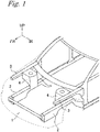
- This embodiment is an example in which a vehicle front structure of the present invention is applied to a vehicle front structure 1 of a sedan-type automobile.
- an arrow FR, an arrow UP, and an arrow IN which are shown in each figure as necessary, respectively indicate a vehicle front direction, a vehicle upward direction, and an inner side in a vehicle width direction.
- front and rear, left and right, and up and down directions it is assumed to indicate front and rear in the vehicle front-rear direction, left and right in the vehicle left-right direction (vehicle width direction), and up and down in the vehicle vertical direction.
- the vehicle front structure 1 includes a front side member 2, an upper side member 3, and a suspension tower 4.
- the respective front side members 2, upper side members 3, and suspension towers 4 are provided on the left and right sides in a front portion of the vehicle body.
- the left and right front side members 2 are formed substantially symmetrically.
- the left and right upper side members 3 are formed substantially symmetrically.
- the left and right suspension towers 4 are formed substantially symmetrically.
- the front side member 2 and the upper side member 3 are framework members of the vehicle body.
- the front side member 2 extends in the front-rear direction.
- the upper side member 3 is disposed above the front side member 2 and on an outer side in the vehicle width direction, and extends in the front-rear direction.
- a front inside panel (not shown) may be joined to the upper side member 3.
- the upper side member 3 may be integrated with the front inside panel.
- the front side member 2 may be formed by the joining of a plurality of members or may be formed with one member.
- the upper side member 3 may be formed by the joining of a plurality of members or may be formed with one member.
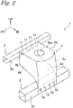
- the suspension tower 4 is bridged over and joined to the front side member 2 and the upper side member 3.
- the front side member 2 and the upper side member 3 are formed such that a cross-sectional shape of at least a portion to be joined to the suspension tower 4 is rectangular.
- the cross-sectional shape of the portion, joined to the suspension tower 4, of the front side member 2 and the upper side member 3 is not limited to this, and may be, for example, U-shaped.
- a wall on the inner side in the vehicle width direction of the front side member 2 is defined as a side wall 2a.
- a wall on the inner side in the vehicle width direction of the upper side member 3 is defined as a side wall 3a.
- the front side member 2 and the upper side member 3 are made of steel, and their tensile strength is preferably 270 MPa or more.
- the suspension tower 4 is disposed so as to cover a suspension device (not shown) and supports the suspension device.
- the suspension tower 4 includes an upper wall 4a, a front wall 4b, a rear wall 4c, a side wall 4d, and a side wall 4e.
- the front wall 4b and the rear wall 4c respectively extend downward from a front end and a rear end of the upper wall 4a.
- the side wall 4d extends downward from an end portion on the inner side in the vehicle width direction of the upper wall 4a.
- the side wall 4e extends downward from an end portion on the outer side in the vehicle width direction of the upper wall 4a.
- a hole 4ah for attaching a suspension device is formed in the upper wall 4a.
- the suspension tower 4 is made of aluminum alloy.
- the suspension tower 4 is preferably formed of JIS 5000 series aluminum alloy being an Al-Mg based alloy.
- the JIS 5000 series aluminum alloy contains magnesium and is therefore excellent in strength and formability.
- the suspension tower 4 may be formed of an aluminum alloy other than the JIS 5000 series aluminum alloy.
- the suspension tower 4 is integrally formed by press working. In other words, the suspension tower 4 has an integral shape, and is in a state of being pressed.
- the suspension tower 4 is formed by pressing a hot-rolled steel plate (thick steel plate) having a thickness of about 3 mm, for example.
- the thickness of the suspension tower 4 is, for example, about 2 to 3 mm.
- the side wall 4d of the suspension tower 4 and the side wall 2a of the front side member 2 are joined with a plurality of joint portions 10.
- the side wall 4e of the suspension tower 4 and the side wall 3a of the upper side member 3 are joined with a plurality of joint portions 11.
- the plurality of joint portions 10 are joined by self-piercing rivet joining or a joining method using pierce metal (hereinafter referred to as pierce metal welding joining).
- the plurality of joint portions 11 are joined by self-piercing rivet joining or pierce metal welding joining.
- the joining methods of the joint portion 10 and the joint portion 11 may be the same or different.
- the joining method of the joint portion 10 is the pierce metal welding joining.
- the joining method of the joint portion 10 is preferably the self-piercing rivet joining, but may be the pierce metal welding joining.
- the joining method of the joint portion 11 is the pierce metal welding joining.
- the joining method of the joint portion 11 is preferably the self-piercing rivet joining, but may be the pierce metal welding joining.
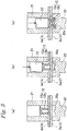
- the side wall 2a of the front side member 2 and the side wall 4d of the suspension tower 4 are overlapped and placed on a die 20.
- a recess 20a is formed on the upper surface of the die 20.
- a tubular guide member 21 is disposed on the side wall 4d of the suspension tower 4, and the side walls 2a and 4d are restricted with the die 20 and the tubular guide member 21.
- a self-piercing rivet 12 is inserted into the tubular guide member 21.
- the self-piercing rivet 12 includes a disc-shaped head portion 12a and a cylindrical shaft portion 12b.
- the diameter of the head portion 12a is larger than the outer diameter of the shaft portion 12b, but may be the same as the outer diameter of the shaft portion 12b.
- a material of the self-piercing rivet 12 is, for example, steel, but it is not limited thereto.
- the head portion 12a of the self-piercing rivet 12 is pressed with a punch 22 and the self-piercing rivet 12 is driven from the side wall 4d of the suspension tower 4 into the side walls 2a and 4d.
- the driving of the self-piercing rivet 12 can be performed by using a general-purpose press machine. As the driving operation progresses, the side walls 2a and 4d are plastically deformed so as to bulge toward the recess 20a side of the die 20. As the driving operation further progresses, the shaft portion 12b of the self-piercing rivet 12 starts spreading from a tip end side. In addition, the shaft portion 12b of the self-piercing rivet 12 cuts into the side wall 4d of the suspension tower 4.
- the self-piercing rivet 12 penetrates the side wall 4d of the suspension tower 4, but does not penetrate the side wall 2a of the front side member 2, and the joining is completed in a state where the head portion 12a of the self-piercing rivet 12 is almost flush with the side wall 4d.
- the shaft portion 12b of the self-piercing rivet 12 spreads and cuts into the side walls 2a and 4d, thereby being firmly fixed to the side walls 2a and 4d due to caulking effect.
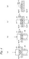
- a pierce metal 13 used in the pierce metal welding joining includes a disc-shaped head portion 13a and a cylindrical shaft portion 13b.
- the diameter of the head portion 13a is larger than the diameter of the shaft portion 13b.
- the tip of the pierce metal 13 has a shape in which the central portion protrudes, but the shape of the tip of the shaft portion 13b of the pierce metal 13 is not limited to this.
- the length of the shaft portion 13b of the pierce metal 13 is set to be not less than the thickness of the side wall 4d of the suspension tower 4.
- the pierce metal 13 is made of a material that can be welded to an object (front side member 2 in this case) to be joined to the suspension tower 4.
- the pierce metal 13 is preferably made of steel.
- the side wall 4d of the suspension tower 4 is placed on a cylindrical die 30. Then, the head portion 13a of the pierce metal 13 is pressed with a punch 31, and the pierce metal 13 is driven into the side wall 4d.
- a portion corresponding to the shaft portion 13b of the pierce metal 13 is punched out in the side wall 4d, and the pierce metal 13 is embedded (fitted) in a state of penetrating the side wall 4d.
- the driving of the pierce metal 13 can be performed by using a general-purpose press machine.
- the side wall 4d of the suspension tower 4 and the side wall 2a of the front side member 2 are overlapped so that the shaft portion 13b of the pierce metal 13 makes contact with the side wall 2a of the front side member 2.
- the side wall 2a and the pierce metal 13 are sandwiched between a pair of spot electrodes 32 and 33, and a current is passed through the pair of spot electrodes 32 and 33 to perform spot welding.
- the pierce metal 13 and a portion in contact with the pierce metal 13 of the side wall 2a are melted, and the shaft portion 13b of the pierce metal 13 and the side wall 2a are welded.
- the side wall 4d of the suspension tower 4 and the side wall 2a of the front side member 2 are joined.
- a press forming process of pressing the aluminum alloy material and integrally forming the suspension tower 4 is performed. Thereafter, the above joining process by self-piercing rivet joining or pierce metal joining is performed.
- the vehicle front structure 1 of the present embodiment has the following features.
- the suspension tower 4 is made of aluminum alloy, the weight of the vehicle front structure 1 can be reduced. In addition, since the suspension tower 4 is integrally formed by press working, it is possible to form a suspension tower 4 without introducing new equipment and to simplify the manufacturing process of the vehicle front structure 1 by preventing the increase in the number of parts.
- the front side member 2 and the upper side member 3 are formed of steel, and are formed of a material different from that of the suspension tower 4 made of aluminum alloy. It is difficult to weld aluminum and iron.
- mechanical joining is used for joining of different materials. Mechanical joining includes rivet joining requiring pilot-hole machining, caulking joining, bolt fastening, and the like.
- suspension tower 4 and at least one of the front side member 2 and the upper side member 3 are joined by self-piercing rivet joining, they can be firmly joined even if the suspension tower 4 and at least one of the front side member 2 and the upper side member 3 are formed of different materials.
- the front side member 2 and/or the upper side member 3 to be joined by self-piercing rivet joining to the suspension tower 4 has a tensile strength of less than 590 MPa, the front side member 2 and/or the upper side member 3 can be deformed by the driving of the self-piercing rivet, to be firmly joined to the suspension tower 4.
- suspension tower 4 and at least one of the front side member 2 and the upper side member 3 are joined by pierce metal welding joining, they can be firmly joined even if the suspension tower 4 and at least one of the front side member 2 and the upper side member 3 are formed of different materials.
- the pierce metal 13 can be embedded in the suspension tower 4 in a penetrating state by being driven into the suspension tower 4. Therefore, when the suspension tower 4 and at least one of the front side member 2 and the upper side member 3 are joined by using the pierce metal 13, it is not necessary for the suspension tower 4 to perform pilot-hole machining for joining. Therefore, the joining process can be simplified as compared with the rivet joining which requires pilot-hole machining, the caulked joining, or the bolt fastening. Therefore, the manufacturing process of the vehicle front structure 1 can be further simplified.
- the front side member 2 and/or the upper side member 3 is spot-welded to the steel pierced metal 13 embedded in the suspension tower 4, so that there is no need to deform the front side member 2 and/or the upper side member 3 for joining. Therefore, the front side member 2 and/or the upper side member 3 to be joined to the suspension tower 4 by pierce metal welding joining can be formed of high strength steel. Thereby, the strength of the vehicle front structure 1 can be increased.
- the strength of the vehicle front structure 1 can be further increased.
- JIS 5000 series aluminum alloy is excellent in strength and formability. Therefore, forming the suspension tower of JIS 5000 series aluminum alloy allows the suspension tower to be integrally formed by press working even if the shape of the suspension tower 4 is deep in the pressing direction.
- the suspension tower 4 and the front side member 2 are joined in the side wall 4d of the suspension tower 4 and the side wall 2a of the front side member 2, but the joint portion is not limited to these.
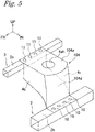
- a side wall 104d of a suspension tower 104 and an upper wall 2b of the front side member 2 may be joined.
- the joining method of the joint portion 10 for joining the suspension tower 4 and the front side member 2 is self-piercing rivet joining or pierce metal welding joining, but other joining methods may be used.
- the joining method of the joint portion 11 for joining the suspension tower 4 and the upper side member 3 is self-piercing rivet joining or pierce metal welding joining, but other joining methods may be used.
- 1 Vehicle front structure
- 2 Front side member
- 3 Upper side member
- 4 Suspension tower
- 10 Joint portion
- 11 Joint portion
- 12 Self-piercing rivet
- 13 Pierce metal
Landscapes
- Engineering & Computer Science (AREA)
- Chemical & Material Sciences (AREA)
- Combustion & Propulsion (AREA)
- Transportation (AREA)
- Mechanical Engineering (AREA)
- Architecture (AREA)
- Structural Engineering (AREA)
- Manufacturing & Machinery (AREA)
- Body Structure For Vehicles (AREA)
Claims (9)
- Fahrzeugfrontaufbau (1) mit:einem Frontseitenelement (2) das in einem Frontabschnitt einer Fahrzeugkarosserie angeordnet ist und sich in Fahrzeugfront-/-heckrichtung erstreckt;einem Oberseitenelement (3), das in einem Fahrzeug oberhalb des Frontseitenelements (2) angeordnet ist und sich in der Fahrzeugfront-/ -heckrichtung erstreckt; undeinem Federbeindom (4), der mit dem Frontseitenelement (2) und dem Oberseitenelement (3) verbunden ist, wobei der Federbeindom (4) aus Aluminiumlegierung besteht,dadurch gekennzeichnet, dassder Federbeindom (4) einstückig durch Pressformen ausgebildet ist,der Federbeindom (4) eine obere Wand (4a) und eine äußere Seitenwand (4e) aufweist, die sich von einem Endabschnitt der oberen Wand (4a) auf einer Außenseite in einer Fahrzeugbreitenrichtung nach unten erstreckt, unddie äußere Seitenwand (4e) mit einer inneren Seitenwand (3a) des Oberseitenelements (3) auf einer Innenseite in der Fahrzeugbreitenrichtung verbunden ist.
- Fahrzeugfrontaufbau (1) nach Anspruch 1, wobeider Federbeindom (4) eine innere Seitenwand (4b) aufweist, die sich von einem Endabschnitt auf einer Innenseite der oberen Wand (4a) in der Fahrzeugbreitenrichtung nach unten erstreckt, unddie innere Seitenwand (4d) mit einer inneren Seitenwand (2a) des Frontseitenelements (2) auf einer Innenseite in der Fahrzeugbreitenrichtung verbunden ist.
- Fahrzeugfrontaufbau (1) nach Anspruch 1 oder 2, wobei der Federbeindom (4) eine vordere Wand (4b), die sich von einem vorderen Ende der oberen Wand (4a) nach unten erstreckt, und eine hintere Wand (4c) aufweist, die sich von einem hinteren Ende der oberen Wand (4a) nach unten erstreckt.
- Fahrzeugfrontaufbau (1) nach einem der Ansprüche 1 bis 3, wobei der Federbeindom (4) und mindestens eines von dem Frontseitenelement (2) und dem Oberseitenelement (3) durch einen Stanzniet (12) verbunden sind, der vom Federbeindom (4) aus eingetrieben ist.
- Fahrzeugfrontaufbau (1) nach Anspruch 4, wobei das mindestens eine von dem Frontseitenelement (2) und dem Oberseitenelement (3) aus Stahl besteht und eine Zugfestigkeit von weniger als 590 MPa hat.
- Fahrzeugfrontaufbau (1) nach einem der Ansprüche 1 bis 3, wobei mindestens eines von dem Frontseitenelement (2) und dem Oberseitenelement (3) aus Stahl besteht und mit dem Federbeindom (4) durch Punktschweißung mit einem Durchstichmetall (13) verbunden ist, das aus Stahl besteht und so in dem Federbeindom (4) eingebettet ist, dass es den Federbeindom (4) durchdringt.
- Fahrzeugfrontaufbau nach Anspruch 6, wobei das mindestens eine von dem Frontseitenelement (2) und dem Oberseitenelement (3) eine Zugfestigkeit von 590 MPa oder mehr hat.
- Fahrzeugfrontaufbau (1) nach einem der Ansprüche 1 bis 7, wobei der Federbeindom (4) aus Aluminiumlegierung der Serie JIS 5000 ausgebildet ist.
- Verfahren zur Herstellung eines Fahrzeugfrontaufbaus (1), mit:einem Pressformschritt, in dem Aluminiumlegierungsmaterial so gepresst wird, dass es einstückig einen Federbeindom (4) ausbildet; undeinem Verbindungsschritt, in dem der Federbeindom (4) mit einem Frontseitenelement (2), das in einem Frontabschnitt eines Fahrzeugs angeordnet ist und sich in einer Fahrzeugfront-/-heckrichtung erstreckt, und einem Oberseitenelement (3) verbunden wird, das in einem Fahrzeug oberhalb des Frontseitenelements (2) angeordnet ist und sich in der Fahrzeugfront-/-heckrichtung erstreckt, wobeider Federbeindom (4) im Pressformschritt so ausgebildet wird, dass er eine obere Wand (4a) und eine äußere Seitenwand (4e) aufweist, die sich von einem Endabschnitt auf einer Außenseite der oberen Wand (4a) in einer Fahrzeugbreitenrichtung nach unten erstreckt, unddie äußere Seitenwand (4a) im Verbindungschritt mit einer inneren Seitenwand (3a) des Oberseitenelements (3) auf einer Innenseite in der Fahrzeugbreitenrichtung verbunden wird.
Applications Claiming Priority (2)
| Application Number | Priority Date | Filing Date | Title |
|---|---|---|---|
| JP2015195672A JP6591849B2 (ja) | 2015-10-01 | 2015-10-01 | 車体前部構造および車体前部構造の製造方法 |
| PCT/JP2016/076140 WO2017056872A1 (ja) | 2015-10-01 | 2016-09-06 | 車体前部構造および車体前部構造の製造方法 |
Publications (3)
| Publication Number | Publication Date |
|---|---|
| EP3357797A1 EP3357797A1 (de) | 2018-08-08 |
| EP3357797A4 EP3357797A4 (de) | 2019-05-22 |
| EP3357797B1 true EP3357797B1 (de) | 2021-11-17 |
Family
ID=58427437
Family Applications (1)
| Application Number | Title | Priority Date | Filing Date |
|---|---|---|---|
| EP16851048.5A Active EP3357797B1 (de) | 2015-10-01 | 2016-09-06 | Fahrzeugfrontaufbau und verfahren zur herstellung davon |
Country Status (5)
| Country | Link |
|---|---|
| US (1) | US10501124B2 (de) |
| EP (1) | EP3357797B1 (de) |
| JP (1) | JP6591849B2 (de) |
| CN (1) | CN108025772A (de) |
| WO (1) | WO2017056872A1 (de) |
Families Citing this family (3)
| Publication number | Priority date | Publication date | Assignee | Title |
|---|---|---|---|---|
| JP6575015B2 (ja) * | 2017-07-07 | 2019-09-18 | 本田技研工業株式会社 | 車体構造 |
| US11390326B2 (en) * | 2020-06-05 | 2022-07-19 | Honda Motor Co., Ltd. | Vehicle front body structure |
| US11685446B2 (en) * | 2021-01-19 | 2023-06-27 | Ford Global Technologies, Llc | Electric vehicle strut tower to body structure interface bracket |
Family Cites Families (18)
| Publication number | Priority date | Publication date | Assignee | Title |
|---|---|---|---|---|
| JPH0810074Y2 (ja) * | 1989-06-02 | 1996-03-27 | マツダ株式会社 | 自動車の前部車体構造 |
| US5102164A (en) * | 1989-07-20 | 1992-04-07 | Mazda Motor Corporation | Vehicle suspension mounting structure |
| US5674627A (en) * | 1994-08-19 | 1997-10-07 | Kawasaki Steel Corporation | Aluminum alloy sheet having excellent press formability and spot weldability |
| JP4241149B2 (ja) * | 2003-04-10 | 2009-03-18 | トヨタ自動車株式会社 | 車両のフロントフェンダエプロン |
| JP4466100B2 (ja) * | 2004-02-05 | 2010-05-26 | 日産自動車株式会社 | ハイブリッド車体構造及びその製造方法 |
| US8109535B2 (en) * | 2004-12-13 | 2012-02-07 | Ford Global Technologies | Sport utility vehicle (SUV) frame architecture for improved vehicle-to-vehicle compatibility |
| JP2007309471A (ja) * | 2006-05-22 | 2007-11-29 | Nissan Motor Co Ltd | 異種金属パネルの接合構造および接合方法 |
| AU2007315647B2 (en) * | 2006-10-31 | 2011-09-01 | Jfe Steel Corporation | Press forming method for metal sheet and frame part for automotive body manufactured thereby |
| JP4523976B2 (ja) * | 2008-03-17 | 2010-08-11 | 本田技研工業株式会社 | 車体前部構造 |
| US7828330B2 (en) * | 2008-03-17 | 2010-11-09 | Honda Motor Co., Ltd. | Vehicle front body structure |
| JP5011265B2 (ja) | 2008-11-05 | 2012-08-29 | 本田技研工業株式会社 | 車体構造 |
| JP5272749B2 (ja) * | 2009-01-23 | 2013-08-28 | トヨタ自動車株式会社 | サスペンションタワー |
| JP5471061B2 (ja) * | 2009-06-23 | 2014-04-16 | 日産自動車株式会社 | サスペンションタワー構造 |
| JP5526644B2 (ja) * | 2009-08-06 | 2014-06-18 | マツダ株式会社 | 車両の車体構造 |
| CN103237648A (zh) * | 2010-12-08 | 2013-08-07 | 丰田自动车株式会社 | 构件连接方法 |
| JP5629244B2 (ja) * | 2011-07-21 | 2014-11-19 | 株式会社神戸製鋼所 | 異材接合部材、異材接合方法 |
| JP5821121B2 (ja) * | 2011-12-22 | 2015-11-24 | ポップリベット・ファスナー株式会社 | 自己穿孔型リベット用ダイ |
| CA2970661C (en) * | 2014-12-15 | 2020-12-22 | Arconic Inc. | Resistance welding fastener, apparatus and methods for joining similar and dissimilar materials |
-
2015
- 2015-10-01 JP JP2015195672A patent/JP6591849B2/ja active Active
-
2016
- 2016-09-06 WO PCT/JP2016/076140 patent/WO2017056872A1/ja not_active Ceased
- 2016-09-06 CN CN201680056957.5A patent/CN108025772A/zh active Pending
- 2016-09-06 EP EP16851048.5A patent/EP3357797B1/de active Active
- 2016-09-06 US US15/764,799 patent/US10501124B2/en active Active
Non-Patent Citations (1)
| Title |
|---|
| None * |
Also Published As
| Publication number | Publication date |
|---|---|
| US10501124B2 (en) | 2019-12-10 |
| WO2017056872A1 (ja) | 2017-04-06 |
| CN108025772A (zh) | 2018-05-11 |
| EP3357797A1 (de) | 2018-08-08 |
| EP3357797A4 (de) | 2019-05-22 |
| JP6591849B2 (ja) | 2019-10-16 |
| US20180273095A1 (en) | 2018-09-27 |
| JP2017065585A (ja) | 2017-04-06 |
Similar Documents
| Publication | Publication Date | Title |
|---|---|---|
| CN105492155B (zh) | 用于连接至少两个板件的方法 | |
| JP6619388B2 (ja) | 異材接合体の製造方法 | |
| US10632560B2 (en) | Method and joining tool for joining two metal elements by riveting and welding | |
| JP6009004B2 (ja) | 異材接合用鍛造リベット及び異材接合方法 | |
| EP3321152B1 (de) | Fahrzeugunterteilstruktur | |
| US20120315109A1 (en) | Metal Members and Assemblies that have Reinforced Punched Holes and Method of Forming the Holes | |
| KR20090123820A (ko) | 강재와 경합금재의 이재 접합 방법 | |
| JP6383434B2 (ja) | 異材接合構造及び異材接合方法 | |
| US20190126987A1 (en) | Method of manufacturing a structural component | |
| EP3578285B1 (de) | Verfahren zum verbinden von unterschiedlichen materialien und körper aus verbundenen unterschiedlichen materialien | |
| US10501124B2 (en) | Vehicle front structure and method for manufacturing same | |
| US20220176486A1 (en) | Joint structure, automotive component, and joint structure manufacturing method | |
| JP2013022622A (ja) | 異材接合用アルミニウム合金部材および異材接合部材、異材接合方法 | |
| KR20110131826A (ko) | 셀프 피어싱 리벳장치 | |
| JP6854139B2 (ja) | 車体前部構造の製造方法 | |
| EP2631022A1 (de) | Matrize für eine Vorrichtung zum Setzen von Stanznieten | |
| US7834292B2 (en) | Method for single side welding of laminate steel | |
| US10843251B2 (en) | Method for joining members | |
| JP6426043B2 (ja) | 異材接合用リベット、異材接合体、及び異材接合方法 | |
| US10315708B2 (en) | Dashboard support for holding an attachment in a motor vehicle | |
| JP2019007623A (ja) | 異材接合用リベット、異材接合体、及び異材接合方法 | |
| KR102304526B1 (ko) | 이종소재 조립장치 | |
| JP2014190518A (ja) | 接合部補強用カラーの取付構造 | |
| US20070044292A1 (en) | Method for blind rivet welding | |
| JP2003202012A (ja) | ナット固定構造 |
Legal Events
| Date | Code | Title | Description |
|---|---|---|---|
| STAA | Information on the status of an ep patent application or granted ep patent |
Free format text: STATUS: THE INTERNATIONAL PUBLICATION HAS BEEN MADE |
|
| PUAI | Public reference made under article 153(3) epc to a published international application that has entered the european phase |
Free format text: ORIGINAL CODE: 0009012 |
|
| STAA | Information on the status of an ep patent application or granted ep patent |
Free format text: STATUS: REQUEST FOR EXAMINATION WAS MADE |
|
| 17P | Request for examination filed |
Effective date: 20180329 |
|
| AK | Designated contracting states |
Kind code of ref document: A1 Designated state(s): AL AT BE BG CH CY CZ DE DK EE ES FI FR GB GR HR HU IE IS IT LI LT LU LV MC MK MT NL NO PL PT RO RS SE SI SK SM TR |
|
| AX | Request for extension of the european patent |
Extension state: BA ME |
|
| DAV | Request for validation of the european patent (deleted) | ||
| DAX | Request for extension of the european patent (deleted) | ||
| A4 | Supplementary search report drawn up and despatched |
Effective date: 20190418 |
|
| RIC1 | Information provided on ipc code assigned before grant |
Ipc: B62D 25/08 20060101AFI20190412BHEP Ipc: B62D 27/02 20060101ALI20190412BHEP Ipc: B62D 29/00 20060101ALI20190412BHEP |
|
| STAA | Information on the status of an ep patent application or granted ep patent |
Free format text: STATUS: EXAMINATION IS IN PROGRESS |
|
| 17Q | First examination report despatched |
Effective date: 20200825 |
|
| GRAP | Despatch of communication of intention to grant a patent |
Free format text: ORIGINAL CODE: EPIDOSNIGR1 |
|
| STAA | Information on the status of an ep patent application or granted ep patent |
Free format text: STATUS: GRANT OF PATENT IS INTENDED |
|
| INTG | Intention to grant announced |
Effective date: 20210624 |
|
| GRAS | Grant fee paid |
Free format text: ORIGINAL CODE: EPIDOSNIGR3 |
|
| GRAA | (expected) grant |
Free format text: ORIGINAL CODE: 0009210 |
|
| STAA | Information on the status of an ep patent application or granted ep patent |
Free format text: STATUS: THE PATENT HAS BEEN GRANTED |
|
| AK | Designated contracting states |
Kind code of ref document: B1 Designated state(s): AL AT BE BG CH CY CZ DE DK EE ES FI FR GB GR HR HU IE IS IT LI LT LU LV MC MK MT NL NO PL PT RO RS SE SI SK SM TR |
|
| REG | Reference to a national code |
Ref country code: GB Ref legal event code: FG4D |
|
| REG | Reference to a national code |
Ref country code: IE Ref legal event code: FG4D |
|
| REG | Reference to a national code |
Ref country code: DE Ref legal event code: R096 Ref document number: 602016066428 Country of ref document: DE |
|
| REG | Reference to a national code |
Ref country code: AT Ref legal event code: REF Ref document number: 1447826 Country of ref document: AT Kind code of ref document: T Effective date: 20211215 |
|
| REG | Reference to a national code |
Ref country code: LT Ref legal event code: MG9D |
|
| REG | Reference to a national code |
Ref country code: NL Ref legal event code: MP Effective date: 20211117 |
|
| REG | Reference to a national code |
Ref country code: AT Ref legal event code: MK05 Ref document number: 1447826 Country of ref document: AT Kind code of ref document: T Effective date: 20211117 |
|
| PG25 | Lapsed in a contracting state [announced via postgrant information from national office to epo] |
Ref country code: RS Free format text: LAPSE BECAUSE OF FAILURE TO SUBMIT A TRANSLATION OF THE DESCRIPTION OR TO PAY THE FEE WITHIN THE PRESCRIBED TIME-LIMIT Effective date: 20211117 Ref country code: LT Free format text: LAPSE BECAUSE OF FAILURE TO SUBMIT A TRANSLATION OF THE DESCRIPTION OR TO PAY THE FEE WITHIN THE PRESCRIBED TIME-LIMIT Effective date: 20211117 Ref country code: FI Free format text: LAPSE BECAUSE OF FAILURE TO SUBMIT A TRANSLATION OF THE DESCRIPTION OR TO PAY THE FEE WITHIN THE PRESCRIBED TIME-LIMIT Effective date: 20211117 Ref country code: BG Free format text: LAPSE BECAUSE OF FAILURE TO SUBMIT A TRANSLATION OF THE DESCRIPTION OR TO PAY THE FEE WITHIN THE PRESCRIBED TIME-LIMIT Effective date: 20220217 Ref country code: AT Free format text: LAPSE BECAUSE OF FAILURE TO SUBMIT A TRANSLATION OF THE DESCRIPTION OR TO PAY THE FEE WITHIN THE PRESCRIBED TIME-LIMIT Effective date: 20211117 |
|
| PG25 | Lapsed in a contracting state [announced via postgrant information from national office to epo] |
Ref country code: IS Free format text: LAPSE BECAUSE OF FAILURE TO SUBMIT A TRANSLATION OF THE DESCRIPTION OR TO PAY THE FEE WITHIN THE PRESCRIBED TIME-LIMIT Effective date: 20220317 Ref country code: SE Free format text: LAPSE BECAUSE OF FAILURE TO SUBMIT A TRANSLATION OF THE DESCRIPTION OR TO PAY THE FEE WITHIN THE PRESCRIBED TIME-LIMIT Effective date: 20211117 Ref country code: PT Free format text: LAPSE BECAUSE OF FAILURE TO SUBMIT A TRANSLATION OF THE DESCRIPTION OR TO PAY THE FEE WITHIN THE PRESCRIBED TIME-LIMIT Effective date: 20220317 Ref country code: PL Free format text: LAPSE BECAUSE OF FAILURE TO SUBMIT A TRANSLATION OF THE DESCRIPTION OR TO PAY THE FEE WITHIN THE PRESCRIBED TIME-LIMIT Effective date: 20211117 Ref country code: NO Free format text: LAPSE BECAUSE OF FAILURE TO SUBMIT A TRANSLATION OF THE DESCRIPTION OR TO PAY THE FEE WITHIN THE PRESCRIBED TIME-LIMIT Effective date: 20220217 Ref country code: NL Free format text: LAPSE BECAUSE OF FAILURE TO SUBMIT A TRANSLATION OF THE DESCRIPTION OR TO PAY THE FEE WITHIN THE PRESCRIBED TIME-LIMIT Effective date: 20211117 Ref country code: LV Free format text: LAPSE BECAUSE OF FAILURE TO SUBMIT A TRANSLATION OF THE DESCRIPTION OR TO PAY THE FEE WITHIN THE PRESCRIBED TIME-LIMIT Effective date: 20211117 Ref country code: HR Free format text: LAPSE BECAUSE OF FAILURE TO SUBMIT A TRANSLATION OF THE DESCRIPTION OR TO PAY THE FEE WITHIN THE PRESCRIBED TIME-LIMIT Effective date: 20211117 Ref country code: GR Free format text: LAPSE BECAUSE OF FAILURE TO SUBMIT A TRANSLATION OF THE DESCRIPTION OR TO PAY THE FEE WITHIN THE PRESCRIBED TIME-LIMIT Effective date: 20220218 Ref country code: ES Free format text: LAPSE BECAUSE OF FAILURE TO SUBMIT A TRANSLATION OF THE DESCRIPTION OR TO PAY THE FEE WITHIN THE PRESCRIBED TIME-LIMIT Effective date: 20211117 |
|
| PG25 | Lapsed in a contracting state [announced via postgrant information from national office to epo] |
Ref country code: SM Free format text: LAPSE BECAUSE OF FAILURE TO SUBMIT A TRANSLATION OF THE DESCRIPTION OR TO PAY THE FEE WITHIN THE PRESCRIBED TIME-LIMIT Effective date: 20211117 Ref country code: SK Free format text: LAPSE BECAUSE OF FAILURE TO SUBMIT A TRANSLATION OF THE DESCRIPTION OR TO PAY THE FEE WITHIN THE PRESCRIBED TIME-LIMIT Effective date: 20211117 Ref country code: RO Free format text: LAPSE BECAUSE OF FAILURE TO SUBMIT A TRANSLATION OF THE DESCRIPTION OR TO PAY THE FEE WITHIN THE PRESCRIBED TIME-LIMIT Effective date: 20211117 Ref country code: EE Free format text: LAPSE BECAUSE OF FAILURE TO SUBMIT A TRANSLATION OF THE DESCRIPTION OR TO PAY THE FEE WITHIN THE PRESCRIBED TIME-LIMIT Effective date: 20211117 Ref country code: DK Free format text: LAPSE BECAUSE OF FAILURE TO SUBMIT A TRANSLATION OF THE DESCRIPTION OR TO PAY THE FEE WITHIN THE PRESCRIBED TIME-LIMIT Effective date: 20211117 Ref country code: CZ Free format text: LAPSE BECAUSE OF FAILURE TO SUBMIT A TRANSLATION OF THE DESCRIPTION OR TO PAY THE FEE WITHIN THE PRESCRIBED TIME-LIMIT Effective date: 20211117 |
|
| REG | Reference to a national code |
Ref country code: DE Ref legal event code: R097 Ref document number: 602016066428 Country of ref document: DE |
|
| PLBE | No opposition filed within time limit |
Free format text: ORIGINAL CODE: 0009261 |
|
| STAA | Information on the status of an ep patent application or granted ep patent |
Free format text: STATUS: NO OPPOSITION FILED WITHIN TIME LIMIT |
|
| 26N | No opposition filed |
Effective date: 20220818 |
|
| PG25 | Lapsed in a contracting state [announced via postgrant information from national office to epo] |
Ref country code: AL Free format text: LAPSE BECAUSE OF FAILURE TO SUBMIT A TRANSLATION OF THE DESCRIPTION OR TO PAY THE FEE WITHIN THE PRESCRIBED TIME-LIMIT Effective date: 20211117 |
|
| PG25 | Lapsed in a contracting state [announced via postgrant information from national office to epo] |
Ref country code: SI Free format text: LAPSE BECAUSE OF FAILURE TO SUBMIT A TRANSLATION OF THE DESCRIPTION OR TO PAY THE FEE WITHIN THE PRESCRIBED TIME-LIMIT Effective date: 20211117 |
|
| PG25 | Lapsed in a contracting state [announced via postgrant information from national office to epo] |
Ref country code: MC Free format text: LAPSE BECAUSE OF FAILURE TO SUBMIT A TRANSLATION OF THE DESCRIPTION OR TO PAY THE FEE WITHIN THE PRESCRIBED TIME-LIMIT Effective date: 20211117 |
|
| REG | Reference to a national code |
Ref country code: CH Ref legal event code: PL |
|
| GBPC | Gb: european patent ceased through non-payment of renewal fee |
Effective date: 20220906 |
|
| REG | Reference to a national code |
Ref country code: BE Ref legal event code: MM Effective date: 20220930 |
|
| PG25 | Lapsed in a contracting state [announced via postgrant information from national office to epo] |
Ref country code: IT Free format text: LAPSE BECAUSE OF FAILURE TO SUBMIT A TRANSLATION OF THE DESCRIPTION OR TO PAY THE FEE WITHIN THE PRESCRIBED TIME-LIMIT Effective date: 20211117 |
|
| P01 | Opt-out of the competence of the unified patent court (upc) registered |
Effective date: 20230523 |
|
| PG25 | Lapsed in a contracting state [announced via postgrant information from national office to epo] |
Ref country code: LU Free format text: LAPSE BECAUSE OF NON-PAYMENT OF DUE FEES Effective date: 20220906 |
|
| PG25 | Lapsed in a contracting state [announced via postgrant information from national office to epo] |
Ref country code: LI Free format text: LAPSE BECAUSE OF NON-PAYMENT OF DUE FEES Effective date: 20220930 Ref country code: IE Free format text: LAPSE BECAUSE OF NON-PAYMENT OF DUE FEES Effective date: 20220906 Ref country code: FR Free format text: LAPSE BECAUSE OF NON-PAYMENT OF DUE FEES Effective date: 20220930 Ref country code: CH Free format text: LAPSE BECAUSE OF NON-PAYMENT OF DUE FEES Effective date: 20220930 |
|
| PG25 | Lapsed in a contracting state [announced via postgrant information from national office to epo] |
Ref country code: BE Free format text: LAPSE BECAUSE OF NON-PAYMENT OF DUE FEES Effective date: 20220930 |
|
| PG25 | Lapsed in a contracting state [announced via postgrant information from national office to epo] |
Ref country code: GB Free format text: LAPSE BECAUSE OF NON-PAYMENT OF DUE FEES Effective date: 20220906 |
|
| PG25 | Lapsed in a contracting state [announced via postgrant information from national office to epo] |
Ref country code: HU Free format text: LAPSE BECAUSE OF FAILURE TO SUBMIT A TRANSLATION OF THE DESCRIPTION OR TO PAY THE FEE WITHIN THE PRESCRIBED TIME-LIMIT; INVALID AB INITIO Effective date: 20160906 |
|
| PG25 | Lapsed in a contracting state [announced via postgrant information from national office to epo] |
Ref country code: CY Free format text: LAPSE BECAUSE OF FAILURE TO SUBMIT A TRANSLATION OF THE DESCRIPTION OR TO PAY THE FEE WITHIN THE PRESCRIBED TIME-LIMIT Effective date: 20211117 |
|
| PG25 | Lapsed in a contracting state [announced via postgrant information from national office to epo] |
Ref country code: MK Free format text: LAPSE BECAUSE OF FAILURE TO SUBMIT A TRANSLATION OF THE DESCRIPTION OR TO PAY THE FEE WITHIN THE PRESCRIBED TIME-LIMIT Effective date: 20211117 |
|
| PG25 | Lapsed in a contracting state [announced via postgrant information from national office to epo] |
Ref country code: MT Free format text: LAPSE BECAUSE OF FAILURE TO SUBMIT A TRANSLATION OF THE DESCRIPTION OR TO PAY THE FEE WITHIN THE PRESCRIBED TIME-LIMIT Effective date: 20211117 |
|
| PGFP | Annual fee paid to national office [announced via postgrant information from national office to epo] |
Ref country code: DE Payment date: 20250702 Year of fee payment: 10 |
|
| PG25 | Lapsed in a contracting state [announced via postgrant information from national office to epo] |
Ref country code: TR Free format text: LAPSE BECAUSE OF FAILURE TO SUBMIT A TRANSLATION OF THE DESCRIPTION OR TO PAY THE FEE WITHIN THE PRESCRIBED TIME-LIMIT Effective date: 20211117 |