EP3357751B1 - Optisches modul für kraftfahrzeug, und positionsverriegelung einer komponente des moduls mithilfe eines elastisch verformbaren einspannelements - Google Patents
Optisches modul für kraftfahrzeug, und positionsverriegelung einer komponente des moduls mithilfe eines elastisch verformbaren einspannelements Download PDFInfo
- Publication number
- EP3357751B1 EP3357751B1 EP18153898.4A EP18153898A EP3357751B1 EP 3357751 B1 EP3357751 B1 EP 3357751B1 EP 18153898 A EP18153898 A EP 18153898A EP 3357751 B1 EP3357751 B1 EP 3357751B1
- Authority
- EP
- European Patent Office
- Prior art keywords
- clamping element
- support
- fan
- compartment
- arms
- Prior art date
- Legal status (The legal status is an assumption and is not a legal conclusion. Google has not performed a legal analysis and makes no representation as to the accuracy of the status listed.)
- Active
Links
Images


Classifications
-
- B—PERFORMING OPERATIONS; TRANSPORTING
- B60—VEHICLES IN GENERAL
- B60Q—ARRANGEMENT OF SIGNALLING OR LIGHTING DEVICES, THE MOUNTING OR SUPPORTING THEREOF OR CIRCUITS THEREFOR, FOR VEHICLES IN GENERAL
- B60Q1/00—Arrangement of optical signalling or lighting devices, the mounting or supporting thereof or circuits therefor
- B60Q1/02—Arrangement of optical signalling or lighting devices, the mounting or supporting thereof or circuits therefor the devices being primarily intended to illuminate the way ahead or to illuminate other areas of way or environments
- B60Q1/04—Arrangement of optical signalling or lighting devices, the mounting or supporting thereof or circuits therefor the devices being primarily intended to illuminate the way ahead or to illuminate other areas of way or environments the devices being headlights
- B60Q1/0483—Arrangement of optical signalling or lighting devices, the mounting or supporting thereof or circuits therefor the devices being primarily intended to illuminate the way ahead or to illuminate other areas of way or environments the devices being headlights mounted on a bracket, e.g. details concerning the mouting of the lamps on the vehicle body
-
- B—PERFORMING OPERATIONS; TRANSPORTING
- B60—VEHICLES IN GENERAL
- B60Q—ARRANGEMENT OF SIGNALLING OR LIGHTING DEVICES, THE MOUNTING OR SUPPORTING THEREOF OR CIRCUITS THEREFOR, FOR VEHICLES IN GENERAL
- B60Q1/00—Arrangement of optical signalling or lighting devices, the mounting or supporting thereof or circuits therefor
- B60Q1/0029—Spatial arrangement
-
- B—PERFORMING OPERATIONS; TRANSPORTING
- B60—VEHICLES IN GENERAL
- B60Q—ARRANGEMENT OF SIGNALLING OR LIGHTING DEVICES, THE MOUNTING OR SUPPORTING THEREOF OR CIRCUITS THEREFOR, FOR VEHICLES IN GENERAL
- B60Q1/00—Arrangement of optical signalling or lighting devices, the mounting or supporting thereof or circuits therefor
- B60Q1/0088—Details of electrical connections
- B60Q1/0094—Arrangement of electronic circuits separated from the light source, e.g. mounting of housings for starter circuits for discharge lamps
-
- F—MECHANICAL ENGINEERING; LIGHTING; HEATING; WEAPONS; BLASTING
- F21—LIGHTING
- F21S—NON-PORTABLE LIGHTING DEVICES; SYSTEMS THEREOF; VEHICLE LIGHTING DEVICES SPECIALLY ADAPTED FOR VEHICLE EXTERIORS
- F21S45/00—Arrangements within vehicle lighting devices specially adapted for vehicle exteriors, for purposes other than emission or distribution of light
- F21S45/40—Cooling of lighting devices
- F21S45/42—Forced cooling
- F21S45/43—Forced cooling using gas
-
- F—MECHANICAL ENGINEERING; LIGHTING; HEATING; WEAPONS; BLASTING
- F21—LIGHTING
- F21S—NON-PORTABLE LIGHTING DEVICES; SYSTEMS THEREOF; VEHICLE LIGHTING DEVICES SPECIALLY ADAPTED FOR VEHICLE EXTERIORS
- F21S45/00—Arrangements within vehicle lighting devices specially adapted for vehicle exteriors, for purposes other than emission or distribution of light
- F21S45/40—Cooling of lighting devices
- F21S45/47—Passive cooling, e.g. using fins, thermal conductive elements or openings
-
- F—MECHANICAL ENGINEERING; LIGHTING; HEATING; WEAPONS; BLASTING
- F21—LIGHTING
- F21S—NON-PORTABLE LIGHTING DEVICES; SYSTEMS THEREOF; VEHICLE LIGHTING DEVICES SPECIALLY ADAPTED FOR VEHICLE EXTERIORS
- F21S45/00—Arrangements within vehicle lighting devices specially adapted for vehicle exteriors, for purposes other than emission or distribution of light
- F21S45/40—Cooling of lighting devices
- F21S45/49—Attachment of the cooling means
-
- F—MECHANICAL ENGINEERING; LIGHTING; HEATING; WEAPONS; BLASTING
- F21—LIGHTING
- F21V—FUNCTIONAL FEATURES OR DETAILS OF LIGHTING DEVICES OR SYSTEMS THEREOF; STRUCTURAL COMBINATIONS OF LIGHTING DEVICES WITH OTHER ARTICLES, NOT OTHERWISE PROVIDED FOR
- F21V17/00—Fastening of component parts of lighting devices, e.g. shades, globes, refractors, reflectors, filters, screens, grids or protective cages
- F21V17/10—Fastening of component parts of lighting devices, e.g. shades, globes, refractors, reflectors, filters, screens, grids or protective cages characterised by specific fastening means or way of fastening
-
- F—MECHANICAL ENGINEERING; LIGHTING; HEATING; WEAPONS; BLASTING
- F21—LIGHTING
- F21V—FUNCTIONAL FEATURES OR DETAILS OF LIGHTING DEVICES OR SYSTEMS THEREOF; STRUCTURAL COMBINATIONS OF LIGHTING DEVICES WITH OTHER ARTICLES, NOT OTHERWISE PROVIDED FOR
- F21V23/00—Arrangement of electric circuit elements in or on lighting devices
- F21V23/04—Arrangement of electric circuit elements in or on lighting devices the elements being switches
-
- F—MECHANICAL ENGINEERING; LIGHTING; HEATING; WEAPONS; BLASTING
- F21—LIGHTING
- F21V—FUNCTIONAL FEATURES OR DETAILS OF LIGHTING DEVICES OR SYSTEMS THEREOF; STRUCTURAL COMBINATIONS OF LIGHTING DEVICES WITH OTHER ARTICLES, NOT OTHERWISE PROVIDED FOR
- F21V29/00—Protecting lighting devices from thermal damage; Cooling or heating arrangements specially adapted for lighting devices or systems
- F21V29/50—Cooling arrangements
- F21V29/60—Cooling arrangements characterised by the use of a forced flow of gas, e.g. air
- F21V29/67—Cooling arrangements characterised by the use of a forced flow of gas, e.g. air characterised by the arrangement of fans
-
- F—MECHANICAL ENGINEERING; LIGHTING; HEATING; WEAPONS; BLASTING
- F21—LIGHTING
- F21V—FUNCTIONAL FEATURES OR DETAILS OF LIGHTING DEVICES OR SYSTEMS THEREOF; STRUCTURAL COMBINATIONS OF LIGHTING DEVICES WITH OTHER ARTICLES, NOT OTHERWISE PROVIDED FOR
- F21V29/00—Protecting lighting devices from thermal damage; Cooling or heating arrangements specially adapted for lighting devices or systems
- F21V29/85—Protecting lighting devices from thermal damage; Cooling or heating arrangements specially adapted for lighting devices or systems characterised by the material
- F21V29/89—Metals
-
- F—MECHANICAL ENGINEERING; LIGHTING; HEATING; WEAPONS; BLASTING
- F21—LIGHTING
- F21W—INDEXING SCHEME ASSOCIATED WITH SUBCLASSES F21K, F21L, F21S and F21V, RELATING TO USES OR APPLICATIONS OF LIGHTING DEVICES OR SYSTEMS
- F21W2102/00—Exterior vehicle lighting devices for illuminating purposes
- F21W2102/10—Arrangement or contour of the emitted light
- F21W2102/13—Arrangement or contour of the emitted light for high-beam region or low-beam region
Definitions
- such an optical module operates with a light source that has the disadvantage of emitting heat. It is therefore equipped with one or more components designed to absorb and/or dissipate this heat.
- This type of module is, for example, equipped with a radiator to keep the module's temperature at a relatively low level and a cooling component, typically in the form of a fan. In this way, the operation of the optical module is not affected by excessively high temperatures.
- the at least one engagement relief comprises a projection formed on a side wall element of the compartment and which has a shoulder or abutment surface, preferably formed behind the engagement relief relative to the general direction of insertion, to retain an associated branch of the clamping element in the clipped position.
- the at least one engagement relief comprises a projection formed on each of the two side wall elements, parallel to the direction of insertion, which delimit the compartment, each of the projections having a shoulder or a stop surface, preferably formed behind the engagement relief relative to the general direction of insertion, to retain an associated branch of the clamping element in the clipped position.
- the support has two side wall elements which delimit between them a receiving space for the functional component, the opening extending transversely between the two side wall elements, the at least one engagement relief comprising a first outwardly projecting relief formed on one of the two side wall elements and a second outwardly projecting relief formed on the other of the two side wall elements, these two reliefs projecting radially outwards.
- Each of the two branches of the clamping element ends with an inwardly bent portion and is respectively retained by one of the first and second reliefs in the clipped position, by engagement of the inwardly bent portion at the rear of the corresponding relief.
- the intermediate base of the clamping element has a change in curvature and is arched inwards, so as to define an inwards arched portion.
- Another object of the invention is to provide a vehicle projector automobile, comprising a headlight housing and an optical module according to the invention in order to perform a lighting and/or signaling function.
- clamping element to lock the mounting position of a functional component other than a fan, for example a control circuit or a plate with a lighting function. It is understood that the clamping element can allow insertion and removal of the functional component in the manner of a drawer.
- the support 2 comprises means 20 for positioning and fixing the optical lens 4 on the support 2. These means cooperate with positioning and fixing means provided on the optical lens 3.
- the optical lens 4 is thus supported by the support 4.
- the optical lens 4 is supported directly by the support 2.
- the bottom wall may have several large passage openings 24 for the air set in motion by the rotor R of the fan 5.
- a foolproof system may optionally be provided to allow the reception of the fan 5 only if it has a shape complementary to a specific member provided in the compartment L and, possibly, only if the fan 5 is turned in a particular direction with always the same face oriented towards the top of the compartment L.
- a guide member 9a may be provided on the side of the bottom 9 to index in translation the end of the movement of insertion of the fan 5 into the compartment L, and also to form a foolproof device when it is desired that the fan 5 have a well-defined orientation.
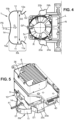
- the fan 5 is a functional component mounted on a part 2a of the support 2 by insertion through the opening 8 following an insertion direction D, bringing it closer to the bottom 9 until it possibly comes into abutment on this bottom 9.
- This insertion direction D can be straight as in the example illustrated in the Figure 1 .
- the functional component to be inserted may be introduced with changes in direction and/or a relative defined displacement clearance, for example by translation in two spatial directions perpendicular to each other and to the insertion direction D.
- the fan 5 may be held by friction, for example by using internal ribs N, when it is fully inserted into the compartment L along the insertion direction D. More generally, if there is relative rotational and/or translational movement play at the start of insertion into the compartment L, such play may advantageously be reduced during the subsequent feeding of the fan 5 (or other functional component/module) towards the bottom 9, for example in an increasing manner until the relative translational and/or rotational movement play disappears or is reduced to a minimal residual relative movement play, at the latest when the operating position is reached.
- the first branch 11 and the second branch 12 each have a free end E1, E2 having, thanks to one or more flexible zones, a certain clearance in a radial direction perpendicular to the plane of symmetry PS.
- Each of the two branches 11, 12 ends here with a portion (11a, E1; 12a, E2;) folded inwards in order to perform a retaining function, by engagement on corresponding projecting engagement reliefs 20a, 20b provided on the elements 21, 22 of side wall.
- Each engagement relief 20a, 20b formed for example directly on the support 2, may have a rear face 24a, 24b, resulting for example from a shoulder in the element 21, 22 of side wall.
- the minimum distance D2 between the branches 11, 12 is measured, here perpendicular to the plane of symmetry PS, between the portions folded inwards.
- the maximum distance D1 between the branches 11, 12, measured in the same direction may correspond to the distance between two first portions, here rectilinear and parallel to each other, which are directly connected to the angles 15a, 15b. These distances D1 and D2 are of course those measured in the resting, non-spread conformation of the clamping element 10. The following relationship may be satisfied: 9 mm ⁇ D1 - D2 ⁇ 35 mm.
- the clamping element 10 can be retained by the two engagement reliefs 20a, 20b, and held in engagement by an elastic return effect, here by each of the two branches 11, 12.
- the clamping element 10 has an intermediate base 14 between the branches 11, 12, intended to come against the rear face 5c of the fan 5 in a mounted and locked functional position of the fan 5 in the compartment L.
- the intermediate base 14 is connected to one and the other of the two branches 11, 12 by a rounded angle iron 15a, 15b, elastically deformable to allow a hinge effect around an axis perpendicular to the insertion direction D.
- the intermediate base 14 extends transversely to the plane PS. In certain variants, this intermediate base 14 may be shorter or even eliminated, for example if the rear face 5c is significantly narrower than the width of the fan 5 or curved or if it has chamfers in a direction transverse to the plane PS.
- the hinge effect is achieved around an axis parallel to the rotation axis X and allows the clamping element 10 to be opened more widely.
- the free ends E1, E2 are formed at an angle to define oblique ramps, which deviate from the plane PS from the folding zone where the minimum distance D2 is defined.
- This configuration makes it possible to gradually separate the branches 11, 12, each ramp acting as a cam follower upon contact against a fixed axial surface (similar to a cam surface) defined by the relief 20a, 20b opposite. The separation is allowed by a deformation of the angles 15a, 15b and/or of the intermediate base 14, which makes it possible to convert the advance of each ramp in the direction of introduction into a rotation/outward separation movement of the branches 11, 12.
- the intermediate base 14 can be narrowed in width, at least in part, relative to the angles 15, 15b, which increases the flexibility in this area of the clamping element 10 and facilitates obtaining a significant spacing between the branches 11, 12.
- the two branches 11, 12 are described here as being parallel to each other in a resting conformation and further apart from each other in the spaced conformation. More generally, the branches 11, 12, parallel or non-parallel to each other at rest, can advantageously have the same capacity to move from a resting position which allows a clamping to be carried out, with axial blocking on the side of the ends of the branches 11, 12, to a more spaced position which allows axial movement in the direction of introduction D and in the opposite direction.
- the locking can result from an essentially linear movement of the clamping element 10, the latter being able to be pushed only at the level of its intermediate part or base 14, for example on a slightly concave face F14 of this intermediate base 14, oriented in the opposite direction relative to the direction of introduction D as illustrated in the figures 1 And 4 .
- each inwardly folded portion of a branch 11 or 12 includes a radial locking section 11a, 12a transverse to the plane PS of symmetry of the clamping element 10.
- a radial section 11a, 11b engages against a rear face 24a, 24b of the relief 20a, 20b at the end of the positioning of the clamping element 10, in a clipped position of this clamping element 10.
- the general U shape of this clamping element 10 allows retention as close as possible to the support 2, along three lateral sides of the compartment L.
- each radial blocking section 11a, 12a extends intermediately between the first portion, here rectilinear, of the branch considered and the free end E1 or E2 of the branch defined in the form of a second portion having a C or J shape.
- the first portion of each branch, forming the portion closest to the angle iron 15a, 15b, can be parallel to the plane of symmetry PS and is typically oriented along the direction of introduction D when the clamping element 10 is approaching and about to engage externally against the side walls 21, 22 of the compartment L.
- the clamping element 10, preferably metallic, is for example made in one piece. It has a shape memory and has sufficient reversibility so that the distances D1 and D2 remain substantially the same after several deformation operations to obtain a spaced conformation of the clamping element 10.
- the clamping element 10 is metallic, for example one and/or the other of the branches 11, 12 with the associated angle iron 15a, 15b.
- each angle iron 15a, 15b has a passage orifice O1, O2 which opens into a contact zone between a wall element 21, 22 and the first portion, here rectilinear, of one of the branches 11, 12.
- the passage orifice O1, O2 is oriented and accessible from the same side as the intermediate base 14, that is to say from the rear.
- the passage orifice O1, O2 can be formed in a corner zone, so as to be able to modify the orientation of a straight working part of a dismantling tool which is inserted through this orifice O1, O2. This can in particular allow lateral movement, going from the intermediate base 14 towards the nearest branch 11, 12 or in the other direction.
- the passage orifice O1, O2 can typically be elongated in a direction away from the intermediate base 14.
- the passage orifice O1 allows the assembly constituted by the angle iron 15a and the associated branch 11 to define a flexible actuable portion PA, which can deviate from the plane PS during the installation of the clamping element 10. More precisely, the introduction of one end of a disassembly tool, such as a screwdriver, through the passage orifice O1 and between the side wall element 21 and the branch 11, allows the branch 11 to be moved radially outwards. This has the effect of unclipping the clamping element 10 as clearly visible in the Figure 5 , the corresponding folded portion 11a, E1 being able to disengage from the relief 20a formed laterally on the support 2.
- another passage orifice O2 can also be provided, allowing the assembly constituted by the angle iron 15b and the associated branch 12 to define another flexible actuable portion. It is understood that the introduction of one end of a disassembly tool, such as a screwdriver, through the passage orifice O2 and between the side wall element 22 and the branch 12, makes it possible to move the branch 12 radially outwards. As in the case previously described where the passage orifice O1 is used, this has the effect of unclipping the clamping element 10 by disengaging the corresponding relief 20b formed externally on the side wall element 22.
- the fan 5 can be removed from the compartment L, by simply pulling in the opposite direction to the direction introduction D.
- the fan 5 may optionally protrude relative to the side wall elements 21, 22 on the side of the opening 8, to facilitate gripping a rear end of the fan 5 during a removal operation.
- the optical module 1 may be part of a motor vehicle headlight, for example by being housed in a headlight housing, in order to perform at least one lighting and/or signaling function.
- the module 1 allows the optical module 1 to be assembled and disassembled easily, and in a manner compatible with installation locations that are difficult to access, for example from the rear of the projector in a vehicle. Such an optical module 1 facilitates the replacement of a functional component that may be changed.
- a metal blade can constitute the clamping element 10 and produce a spring effect which facilitates the engagement at the rear of the reliefs 20a, 20b during locking.
- this clamping element 10 may have a different or shorter branch than the other.
- one of the branches 11, 12 may, if necessary, not engage on the rear of a relief 20a, 20b by moving away for unclipping, but cooperate in a different way to allow the clamping element 10 to be held in position.
- such a branch may be held in a fixed position by magnetic attachment, friction or shape cooperation, optionally by being guided in position along the side wall of the compartment L.
Landscapes
- Engineering & Computer Science (AREA)
- General Engineering & Computer Science (AREA)
- Mechanical Engineering (AREA)
- Non-Portable Lighting Devices Or Systems Thereof (AREA)
- Clamps And Clips (AREA)
- Snaps, Bayonet Connections, Set Pins, And Snap Rings (AREA)
- Mounting Components In General For Electric Apparatus (AREA)
Claims (7)
- Optisches Modul (1) für ein Kraftfahrzeug, umfassend:- einen Träger (2), der ein Fach (L) begrenzt, das über eine Öffnung (8) zugänglich ist,- eine funktionale Komponente, die dazu ausgebildet und eingerichtet ist, in einer Betriebskonfiguration der funktionalen Komponente durch Einsetzen durch die Öffnung (8) hindurch entlang einer allgemeinen Einführungsrichtung (D) in einem Aufnahmeraum des Faches (L) aufgenommen zu werden, wobei die funktionale Komponente ein Lüfter (5) ist, der eine Drehachse (X) eines Rotors (R) mit Flügeln und einen Rahmen, der den Stator (23) des Lüfters bildet, umfasst,- ein Einspannelement (10), das mit zwei Schenkeln (11, 12) versehen ist und dazu ausgebildet und eingerichtet ist, wenn es aufgeklipst ist, den Lüfter (5) in der Betriebskonfiguration zu halten und zu verriegeln, wobei die zwei Schenkel (11, 12) in der aufgeklipsten Position beiderseits der Öffnung (8) des Faches (L) angeordnet sind,- eine Lichtquelle,dadurch gekennzeichnet, dass es mindestens eine Einrasterhebung (20a, 20b) aufweist, die ortsfest bezüglich des Trägers (2) und vorzugsweise direkt am Träger ausgebildet ist und auf der das Einspannelement (10) durch eine elastische Rückstellwirkung mindestens eines der zwei Schenkel (11, 12) in Eingriff gehalten wird, wobei die mindestens eine Einrasterhebung (20a, 20b) ermöglicht, das Einspannelement (10) aufzuklipsen und dabei in einer dem Träger (2) benachbarten aufgeklipsten Position zu halten,dadurch, dass das Einspannelement (10) vom Träger (2) verschieden ist,dadurch, dass das optische Modul (1) eine Reflexionsanordnung aufweist, die durch mehrere Reflektorelemente definiert ist, wobei die Lichtquelle gegenüber einem Reflektorelement (3) der Reflexionsanordnung angeordnet ist, das von einem Teil des Trägers (2) gebildet wird,dadurch, dass der Träger (2) zwei Seitenwandelemente (21, 22) aufweist, die zwischen sich den Aufnahmeraum für den Lüfter begrenzen, wobei sich die Öffnung (8) quer zwischen den Seitenwandelementen (21, 22) erstreckt, um so das Einführen des Lüfters (5) zu ermöglichen, wenn dieser derart ausgerichtet ist, dass seine Drehachse (X) parallel zu den Seitenwandelementen (21, 22) und senkrecht zur allgemeinen Einführungsrichtung (D) ist, wobei die mindestens eine Einrasterhebung (20a, 20b) eine nach außen vorstehende erste Erhebung (20a), die an einem der zwei Seitenwandelemente (21) ausgebildet ist, und eine nach außen vorstehende zweite Erhebung (20b), die an dem anderen der zwei Seitenwandelemente (22) ausgebildet ist, umfasst, wobei diese zwei Erhebungen radial nach außen vorstehen, wobei jeder der zwei Schenkel (11, 12) des Einspannelements (10) in einem Abschnitt endet, der nach innen gebogen ist und jeweils von einer von der ersten und der zweiten Erhebung (20a, 20b) durch Einrasten des nach innen gebogenen Abschnitts hinter der entsprechenden Erhebung in der aufgeklipsten Position gehalten wird,dadurch, dass das Einspannelement (10) eine Zwischenbasis (14) aufweist, die den ersten Schenkel (1) und den zweiten Schenkel (12) so verbindet, dass sie in der aufgeklipsten Position die Öffnung (8) verschließt oder sich gegenüber dieser erstreckt,und dadurch, dass das Einspannelement (10) einen flexiblen betätigbaren Abschnitt (PA) aufweist, um einen der zwei Schenkel (11, 12) abzuspreizen und ein Ausklipsen des Einspannelements (10) in einer gespreizten Form zu ermöglichen.
- Modul nach Anspruch 1, wobei das Einspannelement (10) durch Biegen so verformbar ist, dass es übergehen kann:- aus einer Ruheform, in der die zwei Schenkel (11, 12) im Wesentlichen parallel sind,- in die gespreizte Form, in der die zwei Schenkel (11, 12) weiter voneinander entfernt sind als in der Ruheform.
- Modul nach Anspruch 1 oder 2, wobei die Zwischenbasis (14) mit dem einen und/oder dem anderen der zwei Schenkel (11, 12) durch ein gerundetes Winkelstück (15a, 15b) verbunden ist, wobei das Zwischenstück und/oder das gerundete Winkelstück (15a, 15b) elastisch verformbar sind, um zu ermöglichen, den Schenkel (11, 12), an den das Winkelstück angeschlossen ist, reversibel abzuspreizen.
- Modul nach Anspruch 3, wobei das Winkelstück (15a, 15b) ein Durchgangsloch (01, 02) aufweist, wodurch das Winkelstück (15a, 15b) und der benachbarte Schenkel den flexiblen betätigbaren Abschnitt (PA) definieren, um den entsprechenden Schenkel (11, 12) abzuspreizen, wobei das Abspreizen in Reaktion auf die Einführung eines Endes eines Demontagewerkzeugs, wie etwa eines Schraubendrehers, durch das Durchgangsloch (01, 02) hindurch zwischen ein Seitenwandelement (21, 22) des Faches (L) und den Schenkel erzielt wird.
- Modul nach einem der vorhergehenden Ansprüche, welches eine Lichtquelle umfasst, die in einem optischen Hohlraum (C3) angeordnet ist, der wenigstens teilweise von dem Träger (2) und optischen Mitteln zum Umwandeln einer Strahlung einer Lichtquelle in ein austretendes Lichtbündel begrenzt wird, wobei der Lüfter von den optischen Mitteln verschieden ist und das Fach (L) von dem optischen Hohlraum (C3) getrennt ist.
- Modul nach einem der vorhergehenden Ansprüche, wobei das Einspannelement (10) aus einem Stück, vorzugsweise aus Metall, hergestellt ist.
- Scheinwerfer für ein Kraftfahrzeug, welcher ein Scheinwerfergehäuse und ein optisches Modul (1) nach einem der vorhergehenden Ansprüche umfasst, um eine Beleuchtungs- und/oder Signalisierungsfunktion auszuführen.
Applications Claiming Priority (1)
| Application Number | Priority Date | Filing Date | Title |
|---|---|---|---|
| FR1750971A FR3062612B1 (fr) | 2017-02-06 | 2017-02-06 | Module optique pour vehicule automobile et verrouillage en position d'un composant du module par un element d'enserrement elastiquement deformable |
Publications (2)
| Publication Number | Publication Date |
|---|---|
| EP3357751A1 EP3357751A1 (de) | 2018-08-08 |
| EP3357751B1 true EP3357751B1 (de) | 2025-03-26 |
Family
ID=58455307
Family Applications (1)
| Application Number | Title | Priority Date | Filing Date |
|---|---|---|---|
| EP18153898.4A Active EP3357751B1 (de) | 2017-02-06 | 2018-01-29 | Optisches modul für kraftfahrzeug, und positionsverriegelung einer komponente des moduls mithilfe eines elastisch verformbaren einspannelements |
Country Status (4)
| Country | Link |
|---|---|
| US (1) | US10752159B2 (de) |
| EP (1) | EP3357751B1 (de) |
| CN (2) | CN119802503A (de) |
| FR (1) | FR3062612B1 (de) |
Families Citing this family (8)
| Publication number | Priority date | Publication date | Assignee | Title |
|---|---|---|---|---|
| CN110949531B (zh) * | 2018-09-27 | 2023-10-03 | 宇通客车股份有限公司 | 车辆 |
| DE102018124320A1 (de) * | 2018-10-02 | 2020-04-02 | Automotive Lighting Reutlingen Gmbh | Kraftfahrzeugscheinwerfer und Lüfter hierfür |
| DE102019108882A1 (de) | 2019-04-04 | 2020-10-08 | Valeo Schalter Und Sensoren Gmbh | Halterungsbasisteil zur Befestigung wenigstens eines Kameragehäuses an einem Fahrzeugteil eines Fahrzeugs, Kameragehäuse und Kamerasystem |
| WO2021004777A1 (en) * | 2019-07-10 | 2021-01-14 | Volvo Truck Corporation | A lamp unit housing and a lamp arrangement |
| FR3100598B1 (fr) * | 2019-09-05 | 2025-03-07 | Psa Automobiles Sa | Dispositif anti-vibrations pour un ventilateur de projecteur de véhicule automobile |
| DE102020112963B3 (de) * | 2020-05-13 | 2021-10-07 | HELLA GmbH & Co. KGaA | Lüftersystem für einen Scheinwerfer eines Kraftfahrzeugs, Scheinwerfer und Kraftfahrzeug |
| CN114521085B (zh) * | 2020-11-20 | 2025-01-17 | 联想企业解决方案(新加坡)有限公司 | 计算设备支架及保持系统 |
| DE102021111933A1 (de) | 2021-05-07 | 2022-11-10 | HELLA GmbH & Co. KGaA | Kühlvorrichtung für eine Beleuchtungseinrichtung eines Kraftfahrzeugs |
Citations (4)
| Publication number | Priority date | Publication date | Assignee | Title |
|---|---|---|---|---|
| US20040027807A1 (en) * | 2002-08-06 | 2004-02-12 | Fujitsu Limited | Heat sink, fixing method thereof and electronic apparatus using heat sink |
| JP2007194172A (ja) * | 2006-01-23 | 2007-08-02 | Koito Mfg Co Ltd | 光源モジュール |
| US20080174958A1 (en) * | 2007-01-23 | 2008-07-24 | Sunonwealth Electric Machine Industry Co., Ltd. | Mini-sized heat-dissipating module having an engaging structure |
| JP2010129316A (ja) * | 2008-11-26 | 2010-06-10 | Ichikoh Ind Ltd | 車両用灯具 |
Family Cites Families (32)
| Publication number | Priority date | Publication date | Assignee | Title |
|---|---|---|---|---|
| US4427249A (en) * | 1981-02-02 | 1984-01-24 | Amp Incorporated | Low height ADS connector |
| TW556863U (en) * | 2000-09-05 | 2003-10-01 | Foxconn Prec Components Co Ltd | Fastener of heat sink device |
| US6401806B1 (en) * | 2001-03-29 | 2002-06-11 | Foxconn Precision Components Co., Ltd. | Heat sink assembly |
| JP2003017639A (ja) * | 2001-06-29 | 2003-01-17 | Matsushita Electric Ind Co Ltd | ヒートシンクの取り付け金具およびその取り外し方法 |
| US6640882B2 (en) * | 2001-07-31 | 2003-11-04 | Agilent Technologies, Inc. | Removable mounting clip attaches a motorized fan to an active heat sink and then the entire assembly to a part to be cooled |
| DE20116523U1 (de) * | 2001-10-09 | 2002-02-07 | Automotive Lighting Reutlingen GmbH, 72762 Reutlingen | Lampenfassung sowie Baugruppe bestehend aus Lampenfassung und Reflektor |
| DE10345371A1 (de) * | 2003-09-26 | 2005-04-28 | Zeiss Carl Jena Gmbh | Anordnung zur Bilderzeugung |
| JP4343720B2 (ja) * | 2004-01-23 | 2009-10-14 | 株式会社小糸製作所 | 灯具 |
| US7628521B1 (en) * | 2009-01-15 | 2009-12-08 | Tyc Brother Industrial Co., Ltd. | HID bulb fixing apparatus |
| CN102055114B (zh) * | 2009-11-09 | 2013-03-06 | 仁宝电脑工业股份有限公司 | 可插拔式组件限位结构 |
| EP2327928B1 (de) * | 2009-11-25 | 2018-08-15 | HELLA GmbH & Co. KGaA | Halterung für einen Lüfter einer Beleuchtungseinrichtung sowie Beleuchtungseinrichtung |
| CN103026132A (zh) * | 2010-07-14 | 2013-04-03 | 皇家飞利浦电子股份有限公司 | 具有用于光学器件的安装元件的led照明组件 |
| FR2965039B1 (fr) * | 2010-07-26 | 2016-04-15 | Valeo Vision | Module optique de dispositif d'eclairage et/ou de signalisation d'un vehicule automobile |
| DE102010045848A1 (de) * | 2010-09-17 | 2012-03-22 | Automotive Lighting Reutlingen Gmbh | Kraftfahrzeugscheinwerfer mit einer Gasentladungslampe |
| CN202025899U (zh) * | 2010-12-17 | 2011-11-02 | 富港电子(东莞)有限公司 | 电连接器 |
| US9605843B2 (en) * | 2011-07-11 | 2017-03-28 | Golight, Inc. | LED system and housing for use with halogen light |
| FR2982006B1 (fr) * | 2011-09-13 | 2018-04-27 | Valeo Vision | Module optique a reference commune, pour eclairage et/ou signalisation d'un vehicule automobile |
| FR2998944B1 (fr) * | 2012-11-30 | 2019-06-28 | Valeo Illuminacion | Dispositif d'eclairage et/ou de signalisation pour vehicule automobile |
| JP6235786B2 (ja) * | 2013-03-26 | 2017-11-22 | 株式会社小糸製作所 | 冷却ユニット、および照明装置 |
| DE102013017022A1 (de) * | 2013-10-12 | 2015-04-16 | Daimler Ag | Beleuchtungsvorrichtung für ein Fahrzeug |
| JP6345052B2 (ja) * | 2013-12-20 | 2018-06-20 | 株式会社小糸製作所 | 車輌用前照灯 |
| US9293848B2 (en) * | 2014-05-29 | 2016-03-22 | Ideal Industries, Inc. | Electrical connector for use with printed circuit boards |
| KR20160000297U (ko) * | 2014-07-16 | 2016-01-26 | 에스엘 주식회사 | 차량용 램프의 방열 장치 |
| CN204011181U (zh) * | 2014-07-31 | 2014-12-10 | 宇龙计算机通信科技(深圳)有限公司 | 一种按键以及一种移动终端 |
| CN204088625U (zh) * | 2014-08-08 | 2015-01-07 | 番禺得意精密电子工业有限公司 | 电连接器 |
| KR101666507B1 (ko) * | 2014-09-22 | 2016-10-17 | 에스엘 주식회사 | 차량용 램프 |
| FR3031571B1 (fr) * | 2015-01-09 | 2018-08-10 | Valeo Vision | Module optique pour projecteur de vehicule |
| EP3104061A1 (de) * | 2015-06-09 | 2016-12-14 | Chen-Wei Hsu | Radiator für eine scheinwerferbaugruppe |
| CN108431489B (zh) * | 2015-12-15 | 2021-07-06 | 株式会社小糸制作所 | 车辆用灯具 |
| CN108368923B (zh) * | 2015-12-25 | 2021-09-10 | 株式会社小糸制作所 | 固定部件,自动调心轴承机构,致动器以及灯具 |
| FR3052849B1 (fr) * | 2016-06-15 | 2018-06-15 | Grupo Antolin Besancon | Ampoule pour lampe de vehicule automobile |
| DE102017110740A1 (de) * | 2017-05-17 | 2018-11-22 | HELLA GmbH & Co. KGaA | Aufnahmeanordnung zur Aufnahme eines Lüfters an einem Lichtmodul eines Scheinwerfers für ein Fahrzeug |
-
2017
- 2017-02-06 FR FR1750971A patent/FR3062612B1/fr active Active
-
2018
- 2018-01-29 EP EP18153898.4A patent/EP3357751B1/de active Active
- 2018-02-06 CN CN202510028019.5A patent/CN119802503A/zh active Pending
- 2018-02-06 US US15/889,658 patent/US10752159B2/en active Active
- 2018-02-06 CN CN201810136111.3A patent/CN108397748A/zh active Pending
Patent Citations (4)
| Publication number | Priority date | Publication date | Assignee | Title |
|---|---|---|---|---|
| US20040027807A1 (en) * | 2002-08-06 | 2004-02-12 | Fujitsu Limited | Heat sink, fixing method thereof and electronic apparatus using heat sink |
| JP2007194172A (ja) * | 2006-01-23 | 2007-08-02 | Koito Mfg Co Ltd | 光源モジュール |
| US20080174958A1 (en) * | 2007-01-23 | 2008-07-24 | Sunonwealth Electric Machine Industry Co., Ltd. | Mini-sized heat-dissipating module having an engaging structure |
| JP2010129316A (ja) * | 2008-11-26 | 2010-06-10 | Ichikoh Ind Ltd | 車両用灯具 |
Also Published As
| Publication number | Publication date |
|---|---|
| US20180222379A1 (en) | 2018-08-09 |
| CN119802503A (zh) | 2025-04-11 |
| CN108397748A (zh) | 2018-08-14 |
| EP3357751A1 (de) | 2018-08-08 |
| US10752159B2 (en) | 2020-08-25 |
| FR3062612A1 (fr) | 2018-08-10 |
| FR3062612B1 (fr) | 2020-10-02 |
Similar Documents
| Publication | Publication Date | Title |
|---|---|---|
| EP3357751B1 (de) | Optisches modul für kraftfahrzeug, und positionsverriegelung einer komponente des moduls mithilfe eines elastisch verformbaren einspannelements | |
| EP2598793B1 (de) | Optisches modul einer beleuchtungs- und/oder signalisierungsvorrichtung eines kraftfahrzeuges | |
| EP2926052B1 (de) | Beleuchtungs- und/oder signalisierungsvorrichtung für kraftfahrzeuge | |
| EP2756222B1 (de) | Optisches modul mit gemeinsamer teilereferenz für kraftfahrzeugbeleuchtung und/oder signalisierung | |
| FR2998944B1 (fr) | Dispositif d'eclairage et/ou de signalisation pour vehicule automobile | |
| EP3043107B1 (de) | Optisches modul für kraftfahrzeugscheinwerfer | |
| EP3263977B1 (de) | Leuchtvorrichtung für fahrzeuge mit einem optischen element, das mit einer flexiblen bewehrung verklemmt ist | |
| EP2598797B1 (de) | Optisches modul einer beleuchtungs- und/oder signalisierungsvorrichtung eines kraftfahrzeuges | |
| EP2775197A1 (de) | Vorrichtung zur Beleuchtung und/oder Signalisierung für ein Kraftfahrzeug, die einen Lichtwellenleiter umfasst | |
| EP3243024B1 (de) | Optisches modul für fahrzeugscheinwerfer | |
| EP3201522A1 (de) | Leuchtvorrichtung eines fahrzeugs mit vorrichtung zum positionieren einer elektronischen platine | |
| EP2846079B1 (de) | Leuchtmodul für Beleuchtungs- und/oder Signalisierungsvorrichtung | |
| EP2603391B1 (de) | Vorrichtung zur fixierung ein kühlungselement eines vorderbaues eines kraftfahrzeugs wie ein kühler. | |
| EP3104074A1 (de) | Positionierunganordnung eines led- leuchtmittelträgers auf einem trägerelement und leuchtmodul für eine leuchte oder signalleuchte die eine solche anordnung trägt | |
| EP3486554B1 (de) | Lichtmodul für fahrzeugscheinwerfer | |
| FR3065397A1 (fr) | Accessoire pour une roue d’un vehicule automobile | |
| EP2811222B1 (de) | Einbauleuchte | |
| EP1455134B1 (de) | Befestigungsvorrichtung für eine Lampe | |
| EP3346306B1 (de) | Lösbare anschlussvorrichtung für einen lichtwellenleiter, und anwendung in einem kraftfahrzeug, optisches übertragungsmodul, das mit einer solchen vorrichtung ausgestattet ist | |
| EP3815972A1 (de) | Träger- und vrebindungsvorrichtung einer elektronischen karte für die steuerung eines licht- oder signalisierungsmoduls eines kraftfahrzeugs | |
| EP2730487B1 (de) | Haltebauteil für zwei gegeneinander befestigte Karosserieelemente eines Kraftfahrzeugs | |
| EP2168804A1 (de) | System zur Präzisionsmontage einer Tankklappe in eine Öffnung, die im Blech der Karosserie eines Kraftfahrzeugs erzeugt wurde | |
| EP3966497A1 (de) | Signalisierungsmodul für kraftfahrzeuge und mit diesem modul ausgerüstetes fahrzeug | |
| EP3628877A1 (de) | Käfigmutter-vorrichtung für eine montage auf einem hohlen ständer | |
| FR3052832A3 (fr) | Systeme de commande d'embrayage dote d'un recepteur concentrique hydraulique |
Legal Events
| Date | Code | Title | Description |
|---|---|---|---|
| PUAI | Public reference made under article 153(3) epc to a published international application that has entered the european phase |
Free format text: ORIGINAL CODE: 0009012 |
|
| STAA | Information on the status of an ep patent application or granted ep patent |
Free format text: STATUS: REQUEST FOR EXAMINATION WAS MADE |
|
| 17P | Request for examination filed |
Effective date: 20180129 |
|
| AK | Designated contracting states |
Kind code of ref document: A1 Designated state(s): AL AT BE BG CH CY CZ DE DK EE ES FI FR GB GR HR HU IE IS IT LI LT LU LV MC MK MT NL NO PL PT RO RS SE SI SK SM TR |
|
| AX | Request for extension of the european patent |
Extension state: BA ME |
|
| STAA | Information on the status of an ep patent application or granted ep patent |
Free format text: STATUS: EXAMINATION IS IN PROGRESS |
|
| 17Q | First examination report despatched |
Effective date: 20211025 |
|
| P01 | Opt-out of the competence of the unified patent court (upc) registered |
Effective date: 20230528 |
|
| GRAP | Despatch of communication of intention to grant a patent |
Free format text: ORIGINAL CODE: EPIDOSNIGR1 |
|
| STAA | Information on the status of an ep patent application or granted ep patent |
Free format text: STATUS: GRANT OF PATENT IS INTENDED |
|
| INTG | Intention to grant announced |
Effective date: 20241017 |
|
| GRAS | Grant fee paid |
Free format text: ORIGINAL CODE: EPIDOSNIGR3 |
|
| GRAA | (expected) grant |
Free format text: ORIGINAL CODE: 0009210 |
|
| STAA | Information on the status of an ep patent application or granted ep patent |
Free format text: STATUS: THE PATENT HAS BEEN GRANTED |
|
| AK | Designated contracting states |
Kind code of ref document: B1 Designated state(s): AL AT BE BG CH CY CZ DE DK EE ES FI FR GB GR HR HU IE IS IT LI LT LU LV MC MK MT NL NO PL PT RO RS SE SI SK SM TR |
|
| REG | Reference to a national code |
Ref country code: GB Ref legal event code: FG4D Free format text: NOT ENGLISH |
|
| REG | Reference to a national code |
Ref country code: CH Ref legal event code: EP |
|
| REG | Reference to a national code |
Ref country code: DE Ref legal event code: R096 Ref document number: 602018080402 Country of ref document: DE |
|
| REG | Reference to a national code |
Ref country code: IE Ref legal event code: FG4D Free format text: LANGUAGE OF EP DOCUMENT: FRENCH |
|
| PG25 | Lapsed in a contracting state [announced via postgrant information from national office to epo] |
Ref country code: RS Free format text: LAPSE BECAUSE OF FAILURE TO SUBMIT A TRANSLATION OF THE DESCRIPTION OR TO PAY THE FEE WITHIN THE PRESCRIBED TIME-LIMIT Effective date: 20250626 |
|
| PG25 | Lapsed in a contracting state [announced via postgrant information from national office to epo] |
Ref country code: FI Free format text: LAPSE BECAUSE OF FAILURE TO SUBMIT A TRANSLATION OF THE DESCRIPTION OR TO PAY THE FEE WITHIN THE PRESCRIBED TIME-LIMIT Effective date: 20250326 |
|
| REG | Reference to a national code |
Ref country code: LT Ref legal event code: MG9D |
|
| PG25 | Lapsed in a contracting state [announced via postgrant information from national office to epo] |
Ref country code: NO Free format text: LAPSE BECAUSE OF FAILURE TO SUBMIT A TRANSLATION OF THE DESCRIPTION OR TO PAY THE FEE WITHIN THE PRESCRIBED TIME-LIMIT Effective date: 20250626 |
|
| PG25 | Lapsed in a contracting state [announced via postgrant information from national office to epo] |
Ref country code: HR Free format text: LAPSE BECAUSE OF FAILURE TO SUBMIT A TRANSLATION OF THE DESCRIPTION OR TO PAY THE FEE WITHIN THE PRESCRIBED TIME-LIMIT Effective date: 20250326 |
|
| PG25 | Lapsed in a contracting state [announced via postgrant information from national office to epo] |
Ref country code: LV Free format text: LAPSE BECAUSE OF FAILURE TO SUBMIT A TRANSLATION OF THE DESCRIPTION OR TO PAY THE FEE WITHIN THE PRESCRIBED TIME-LIMIT Effective date: 20250326 |
|
| PG25 | Lapsed in a contracting state [announced via postgrant information from national office to epo] |
Ref country code: GR Free format text: LAPSE BECAUSE OF FAILURE TO SUBMIT A TRANSLATION OF THE DESCRIPTION OR TO PAY THE FEE WITHIN THE PRESCRIBED TIME-LIMIT Effective date: 20250627 Ref country code: BG Free format text: LAPSE BECAUSE OF FAILURE TO SUBMIT A TRANSLATION OF THE DESCRIPTION OR TO PAY THE FEE WITHIN THE PRESCRIBED TIME-LIMIT Effective date: 20250326 |
|
| REG | Reference to a national code |
Ref country code: NL Ref legal event code: MP Effective date: 20250326 |
|
| PG25 | Lapsed in a contracting state [announced via postgrant information from national office to epo] |
Ref country code: NL Free format text: LAPSE BECAUSE OF FAILURE TO SUBMIT A TRANSLATION OF THE DESCRIPTION OR TO PAY THE FEE WITHIN THE PRESCRIBED TIME-LIMIT Effective date: 20250326 |
|
| PG25 | Lapsed in a contracting state [announced via postgrant information from national office to epo] |
Ref country code: SE Free format text: LAPSE BECAUSE OF FAILURE TO SUBMIT A TRANSLATION OF THE DESCRIPTION OR TO PAY THE FEE WITHIN THE PRESCRIBED TIME-LIMIT Effective date: 20250326 |
|
| REG | Reference to a national code |
Ref country code: AT Ref legal event code: MK05 Ref document number: 1778751 Country of ref document: AT Kind code of ref document: T Effective date: 20250326 |
|
| PG25 | Lapsed in a contracting state [announced via postgrant information from national office to epo] |
Ref country code: SM Free format text: LAPSE BECAUSE OF FAILURE TO SUBMIT A TRANSLATION OF THE DESCRIPTION OR TO PAY THE FEE WITHIN THE PRESCRIBED TIME-LIMIT Effective date: 20250326 |
|
| PG25 | Lapsed in a contracting state [announced via postgrant information from national office to epo] |
Ref country code: ES Free format text: LAPSE BECAUSE OF FAILURE TO SUBMIT A TRANSLATION OF THE DESCRIPTION OR TO PAY THE FEE WITHIN THE PRESCRIBED TIME-LIMIT Effective date: 20250326 Ref country code: PT Free format text: LAPSE BECAUSE OF FAILURE TO SUBMIT A TRANSLATION OF THE DESCRIPTION OR TO PAY THE FEE WITHIN THE PRESCRIBED TIME-LIMIT Effective date: 20250728 |
|
| PG25 | Lapsed in a contracting state [announced via postgrant information from national office to epo] |
Ref country code: IT Free format text: LAPSE BECAUSE OF FAILURE TO SUBMIT A TRANSLATION OF THE DESCRIPTION OR TO PAY THE FEE WITHIN THE PRESCRIBED TIME-LIMIT Effective date: 20250326 Ref country code: PL Free format text: LAPSE BECAUSE OF FAILURE TO SUBMIT A TRANSLATION OF THE DESCRIPTION OR TO PAY THE FEE WITHIN THE PRESCRIBED TIME-LIMIT Effective date: 20250326 |
|
| PG25 | Lapsed in a contracting state [announced via postgrant information from national office to epo] |
Ref country code: AT Free format text: LAPSE BECAUSE OF FAILURE TO SUBMIT A TRANSLATION OF THE DESCRIPTION OR TO PAY THE FEE WITHIN THE PRESCRIBED TIME-LIMIT Effective date: 20250326 |
|
| PG25 | Lapsed in a contracting state [announced via postgrant information from national office to epo] |
Ref country code: EE Free format text: LAPSE BECAUSE OF FAILURE TO SUBMIT A TRANSLATION OF THE DESCRIPTION OR TO PAY THE FEE WITHIN THE PRESCRIBED TIME-LIMIT Effective date: 20250326 |
|
| PG25 | Lapsed in a contracting state [announced via postgrant information from national office to epo] |
Ref country code: RO Free format text: LAPSE BECAUSE OF FAILURE TO SUBMIT A TRANSLATION OF THE DESCRIPTION OR TO PAY THE FEE WITHIN THE PRESCRIBED TIME-LIMIT Effective date: 20250326 |
|
| PG25 | Lapsed in a contracting state [announced via postgrant information from national office to epo] |
Ref country code: SK Free format text: LAPSE BECAUSE OF FAILURE TO SUBMIT A TRANSLATION OF THE DESCRIPTION OR TO PAY THE FEE WITHIN THE PRESCRIBED TIME-LIMIT Effective date: 20250326 |
|
| PG25 | Lapsed in a contracting state [announced via postgrant information from national office to epo] |
Ref country code: IS Free format text: LAPSE BECAUSE OF FAILURE TO SUBMIT A TRANSLATION OF THE DESCRIPTION OR TO PAY THE FEE WITHIN THE PRESCRIBED TIME-LIMIT Effective date: 20250726 |
|
| REG | Reference to a national code |
Ref country code: DE Ref legal event code: R097 Ref document number: 602018080402 Country of ref document: DE |
|
| PG25 | Lapsed in a contracting state [announced via postgrant information from national office to epo] |
Ref country code: DK Free format text: LAPSE BECAUSE OF FAILURE TO SUBMIT A TRANSLATION OF THE DESCRIPTION OR TO PAY THE FEE WITHIN THE PRESCRIBED TIME-LIMIT Effective date: 20250326 |
|
| PG25 | Lapsed in a contracting state [announced via postgrant information from national office to epo] |
Ref country code: CZ Free format text: LAPSE BECAUSE OF FAILURE TO SUBMIT A TRANSLATION OF THE DESCRIPTION OR TO PAY THE FEE WITHIN THE PRESCRIBED TIME-LIMIT Effective date: 20250326 |
|
| PLBE | No opposition filed within time limit |
Free format text: ORIGINAL CODE: 0009261 |
|
| STAA | Information on the status of an ep patent application or granted ep patent |
Free format text: STATUS: NO OPPOSITION FILED WITHIN TIME LIMIT |
|
| REG | Reference to a national code |
Ref country code: CH Ref legal event code: L10 Free format text: ST27 STATUS EVENT CODE: U-0-0-L10-L00 (AS PROVIDED BY THE NATIONAL OFFICE) Effective date: 20260211 |
|
| 26N | No opposition filed |
Effective date: 20260105 |
|
| PGFP | Annual fee paid to national office [announced via postgrant information from national office to epo] |
Ref country code: DE Payment date: 20260114 Year of fee payment: 9 |
|
| PGFP | Annual fee paid to national office [announced via postgrant information from national office to epo] |
Ref country code: FR Payment date: 20260128 Year of fee payment: 9 |