EP3355809B1 - Circuits d'alimentation en tension continue isolée (dc) pour instruments chirurgicaux - Google Patents
Circuits d'alimentation en tension continue isolée (dc) pour instruments chirurgicaux Download PDFInfo
- Publication number
- EP3355809B1 EP3355809B1 EP16782117.2A EP16782117A EP3355809B1 EP 3355809 B1 EP3355809 B1 EP 3355809B1 EP 16782117 A EP16782117 A EP 16782117A EP 3355809 B1 EP3355809 B1 EP 3355809B1
- Authority
- EP
- European Patent Office
- Prior art keywords
- generator
- circuit
- ultrasonic
- surgical instrument
- output
- Prior art date
- Legal status (The legal status is an assumption and is not a legal conclusion. Google has not performed a legal analysis and makes no representation as to the accuracy of the status listed.)
- Active
Links
- 239000012636 effector Substances 0.000 claims description 47
- 230000015654 memory Effects 0.000 claims description 33
- 238000001914 filtration Methods 0.000 claims description 7
- 230000004962 physiological condition Effects 0.000 claims 1
- 238000002560 therapeutic procedure Methods 0.000 claims 1
- 210000001519 tissue Anatomy 0.000 description 102
- 238000004891 communication Methods 0.000 description 64
- 230000007246 mechanism Effects 0.000 description 40
- 238000000034 method Methods 0.000 description 37
- 238000012544 monitoring process Methods 0.000 description 24
- 238000004422 calculation algorithm Methods 0.000 description 22
- 238000004146 energy storage Methods 0.000 description 18
- 230000006870 function Effects 0.000 description 15
- 239000003990 capacitor Substances 0.000 description 14
- 230000015271 coagulation Effects 0.000 description 14
- 238000005345 coagulation Methods 0.000 description 14
- 238000010586 diagram Methods 0.000 description 13
- 238000003860 storage Methods 0.000 description 13
- 238000005520 cutting process Methods 0.000 description 12
- 238000002955 isolation Methods 0.000 description 12
- 230000008859 change Effects 0.000 description 11
- 230000008569 process Effects 0.000 description 10
- 238000004088 simulation Methods 0.000 description 10
- 238000001356 surgical procedure Methods 0.000 description 9
- 230000000007 visual effect Effects 0.000 description 9
- 238000007789 sealing Methods 0.000 description 8
- 230000003068 static effect Effects 0.000 description 8
- 230000004913 activation Effects 0.000 description 7
- 238000013461 design Methods 0.000 description 7
- 230000000694 effects Effects 0.000 description 7
- 238000005259 measurement Methods 0.000 description 7
- 230000007704 transition Effects 0.000 description 7
- 230000000903 blocking effect Effects 0.000 description 6
- 230000001419 dependent effect Effects 0.000 description 6
- 238000004520 electroporation Methods 0.000 description 6
- 230000002427 irreversible effect Effects 0.000 description 6
- 230000000670 limiting effect Effects 0.000 description 6
- 238000012986 modification Methods 0.000 description 6
- 230000004048 modification Effects 0.000 description 6
- 230000002441 reversible effect Effects 0.000 description 6
- 230000015572 biosynthetic process Effects 0.000 description 5
- 230000003750 conditioning effect Effects 0.000 description 5
- SYHGEUNFJIGTRX-UHFFFAOYSA-N methylenedioxypyrovalerone Chemical compound C=1C=C2OCOC2=CC=1C(=O)C(CCC)N1CCCC1 SYHGEUNFJIGTRX-UHFFFAOYSA-N 0.000 description 5
- 238000012545 processing Methods 0.000 description 5
- 230000002829 reductive effect Effects 0.000 description 5
- 239000000523 sample Substances 0.000 description 5
- 238000005070 sampling Methods 0.000 description 5
- 238000003786 synthesis reaction Methods 0.000 description 5
- 230000001225 therapeutic effect Effects 0.000 description 5
- 238000004590 computer program Methods 0.000 description 4
- 239000004020 conductor Substances 0.000 description 4
- 238000010276 construction Methods 0.000 description 4
- 230000014509 gene expression Effects 0.000 description 4
- 230000005855 radiation Effects 0.000 description 4
- 230000004044 response Effects 0.000 description 4
- 230000008901 benefit Effects 0.000 description 3
- 230000005540 biological transmission Effects 0.000 description 3
- 210000004204 blood vessel Anatomy 0.000 description 3
- 238000004140 cleaning Methods 0.000 description 3
- 238000010438 heat treatment Methods 0.000 description 3
- 239000000463 material Substances 0.000 description 3
- 230000009471 action Effects 0.000 description 2
- 230000003466 anti-cipated effect Effects 0.000 description 2
- 238000004364 calculation method Methods 0.000 description 2
- 238000006243 chemical reaction Methods 0.000 description 2
- 230000001112 coagulating effect Effects 0.000 description 2
- 210000002808 connective tissue Anatomy 0.000 description 2
- 238000012885 constant function Methods 0.000 description 2
- 230000007423 decrease Effects 0.000 description 2
- 230000000881 depressing effect Effects 0.000 description 2
- 230000000994 depressogenic effect Effects 0.000 description 2
- 238000002405 diagnostic procedure Methods 0.000 description 2
- 230000009977 dual effect Effects 0.000 description 2
- 238000005516 engineering process Methods 0.000 description 2
- 230000005669 field effect Effects 0.000 description 2
- 230000020169 heat generation Effects 0.000 description 2
- 230000002439 hemostatic effect Effects 0.000 description 2
- 238000002847 impedance measurement Methods 0.000 description 2
- 238000007726 management method Methods 0.000 description 2
- 210000003205 muscle Anatomy 0.000 description 2
- 230000002093 peripheral effect Effects 0.000 description 2
- 230000001953 sensory effect Effects 0.000 description 2
- 230000001360 synchronised effect Effects 0.000 description 2
- 238000004804 winding Methods 0.000 description 2
- 241000894006 Bacteria Species 0.000 description 1
- 102000008186 Collagen Human genes 0.000 description 1
- 108010035532 Collagen Proteins 0.000 description 1
- IAYPIBMASNFSPL-UHFFFAOYSA-N Ethylene oxide Chemical compound C1CO1 IAYPIBMASNFSPL-UHFFFAOYSA-N 0.000 description 1
- 244000187656 Eucalyptus cornuta Species 0.000 description 1
- 239000004775 Tyvek Substances 0.000 description 1
- 229920000690 Tyvek Polymers 0.000 description 1
- 230000003213 activating effect Effects 0.000 description 1
- 230000006978 adaptation Effects 0.000 description 1
- 238000013019 agitation Methods 0.000 description 1
- 230000003321 amplification Effects 0.000 description 1
- 238000003491 array Methods 0.000 description 1
- 230000033228 biological regulation Effects 0.000 description 1
- 229920001436 collagen Polymers 0.000 description 1
- 230000001010 compromised effect Effects 0.000 description 1
- 230000001143 conditioned effect Effects 0.000 description 1
- 230000007812 deficiency Effects 0.000 description 1
- 238000001514 detection method Methods 0.000 description 1
- 229920005994 diacetyl cellulose Polymers 0.000 description 1
- 238000002224 dissection Methods 0.000 description 1
- 238000009826 distribution Methods 0.000 description 1
- 238000012976 endoscopic surgical procedure Methods 0.000 description 1
- 230000002708 enhancing effect Effects 0.000 description 1
- 238000011156 evaluation Methods 0.000 description 1
- 239000000835 fiber Substances 0.000 description 1
- 230000007274 generation of a signal involved in cell-cell signaling Effects 0.000 description 1
- 230000023597 hemostasis Effects 0.000 description 1
- 238000005286 illumination Methods 0.000 description 1
- 208000014674 injury Diseases 0.000 description 1
- 238000012830 laparoscopic surgical procedure Methods 0.000 description 1
- 239000004973 liquid crystal related substance Substances 0.000 description 1
- 229910044991 metal oxide Inorganic materials 0.000 description 1
- 150000004706 metal oxides Chemical class 0.000 description 1
- 230000000116 mitigating effect Effects 0.000 description 1
- 239000003607 modifier Substances 0.000 description 1
- 230000002232 neuromuscular Effects 0.000 description 1
- 238000003199 nucleic acid amplification method Methods 0.000 description 1
- 238000002355 open surgical procedure Methods 0.000 description 1
- 230000008520 organization Effects 0.000 description 1
- 230000003071 parasitic effect Effects 0.000 description 1
- 230000000737 periodic effect Effects 0.000 description 1
- 102000004169 proteins and genes Human genes 0.000 description 1
- 108090000623 proteins and genes Proteins 0.000 description 1
- 239000004065 semiconductor Substances 0.000 description 1
- 238000007493 shaping process Methods 0.000 description 1
- 210000004872 soft tissue Anatomy 0.000 description 1
- 239000007787 solid Substances 0.000 description 1
- 230000001954 sterilising effect Effects 0.000 description 1
- 238000004659 sterilization and disinfection Methods 0.000 description 1
- 230000000638 stimulation Effects 0.000 description 1
- 238000006467 substitution reaction Methods 0.000 description 1
- 230000008733 trauma Effects 0.000 description 1
- 238000002604 ultrasonography Methods 0.000 description 1
- 238000003466 welding Methods 0.000 description 1
Images


Classifications
-
- A—HUMAN NECESSITIES
- A61—MEDICAL OR VETERINARY SCIENCE; HYGIENE
- A61B—DIAGNOSIS; SURGERY; IDENTIFICATION
- A61B18/00—Surgical instruments, devices or methods for transferring non-mechanical forms of energy to or from the body
- A61B18/04—Surgical instruments, devices or methods for transferring non-mechanical forms of energy to or from the body by heating
- A61B18/12—Surgical instruments, devices or methods for transferring non-mechanical forms of energy to or from the body by heating by passing a current through the tissue to be heated, e.g. high-frequency current
- A61B18/14—Probes or electrodes therefor
- A61B18/1442—Probes having pivoting end effectors, e.g. forceps
- A61B18/1445—Probes having pivoting end effectors, e.g. forceps at the distal end of a shaft, e.g. forceps or scissors at the end of a rigid rod
-
- A—HUMAN NECESSITIES
- A61—MEDICAL OR VETERINARY SCIENCE; HYGIENE
- A61B—DIAGNOSIS; SURGERY; IDENTIFICATION
- A61B18/00—Surgical instruments, devices or methods for transferring non-mechanical forms of energy to or from the body
- A61B18/04—Surgical instruments, devices or methods for transferring non-mechanical forms of energy to or from the body by heating
- A61B18/12—Surgical instruments, devices or methods for transferring non-mechanical forms of energy to or from the body by heating by passing a current through the tissue to be heated, e.g. high-frequency current
- A61B18/1206—Generators therefor
- A61B18/1233—Generators therefor with circuits for assuring patient safety
-
- A—HUMAN NECESSITIES
- A61—MEDICAL OR VETERINARY SCIENCE; HYGIENE
- A61B—DIAGNOSIS; SURGERY; IDENTIFICATION
- A61B17/00—Surgical instruments, devices or methods, e.g. tourniquets
- A61B17/32—Surgical cutting instruments
- A61B17/320068—Surgical cutting instruments using mechanical vibrations, e.g. ultrasonic
- A61B2017/320071—Surgical cutting instruments using mechanical vibrations, e.g. ultrasonic with articulating means for working tip
-
- A—HUMAN NECESSITIES
- A61—MEDICAL OR VETERINARY SCIENCE; HYGIENE
- A61B—DIAGNOSIS; SURGERY; IDENTIFICATION
- A61B17/00—Surgical instruments, devices or methods, e.g. tourniquets
- A61B17/32—Surgical cutting instruments
- A61B17/320068—Surgical cutting instruments using mechanical vibrations, e.g. ultrasonic
- A61B17/320092—Surgical cutting instruments using mechanical vibrations, e.g. ultrasonic with additional movable means for clamping or cutting tissue, e.g. with a pivoting jaw
- A61B2017/320094—Surgical cutting instruments using mechanical vibrations, e.g. ultrasonic with additional movable means for clamping or cutting tissue, e.g. with a pivoting jaw additional movable means performing clamping operation
-
- A—HUMAN NECESSITIES
- A61—MEDICAL OR VETERINARY SCIENCE; HYGIENE
- A61B—DIAGNOSIS; SURGERY; IDENTIFICATION
- A61B17/00—Surgical instruments, devices or methods, e.g. tourniquets
- A61B17/32—Surgical cutting instruments
- A61B17/320068—Surgical cutting instruments using mechanical vibrations, e.g. ultrasonic
- A61B17/320092—Surgical cutting instruments using mechanical vibrations, e.g. ultrasonic with additional movable means for clamping or cutting tissue, e.g. with a pivoting jaw
- A61B2017/320095—Surgical cutting instruments using mechanical vibrations, e.g. ultrasonic with additional movable means for clamping or cutting tissue, e.g. with a pivoting jaw with sealing or cauterizing means
-
- A—HUMAN NECESSITIES
- A61—MEDICAL OR VETERINARY SCIENCE; HYGIENE
- A61B—DIAGNOSIS; SURGERY; IDENTIFICATION
- A61B18/00—Surgical instruments, devices or methods for transferring non-mechanical forms of energy to or from the body
- A61B2018/00053—Mechanical features of the instrument of device
- A61B2018/00172—Connectors and adapters therefor
- A61B2018/00178—Electrical connectors
-
- A—HUMAN NECESSITIES
- A61—MEDICAL OR VETERINARY SCIENCE; HYGIENE
- A61B—DIAGNOSIS; SURGERY; IDENTIFICATION
- A61B18/00—Surgical instruments, devices or methods for transferring non-mechanical forms of energy to or from the body
- A61B2018/00571—Surgical instruments, devices or methods for transferring non-mechanical forms of energy to or from the body for achieving a particular surgical effect
- A61B2018/00601—Cutting
-
- A—HUMAN NECESSITIES
- A61—MEDICAL OR VETERINARY SCIENCE; HYGIENE
- A61B—DIAGNOSIS; SURGERY; IDENTIFICATION
- A61B18/00—Surgical instruments, devices or methods for transferring non-mechanical forms of energy to or from the body
- A61B2018/00571—Surgical instruments, devices or methods for transferring non-mechanical forms of energy to or from the body for achieving a particular surgical effect
- A61B2018/00607—Coagulation and cutting with the same instrument
-
- A—HUMAN NECESSITIES
- A61—MEDICAL OR VETERINARY SCIENCE; HYGIENE
- A61B—DIAGNOSIS; SURGERY; IDENTIFICATION
- A61B18/00—Surgical instruments, devices or methods for transferring non-mechanical forms of energy to or from the body
- A61B2018/00571—Surgical instruments, devices or methods for transferring non-mechanical forms of energy to or from the body for achieving a particular surgical effect
- A61B2018/0063—Sealing
-
- A—HUMAN NECESSITIES
- A61—MEDICAL OR VETERINARY SCIENCE; HYGIENE
- A61B—DIAGNOSIS; SURGERY; IDENTIFICATION
- A61B18/00—Surgical instruments, devices or methods for transferring non-mechanical forms of energy to or from the body
- A61B2018/00636—Sensing and controlling the application of energy
- A61B2018/00642—Sensing and controlling the application of energy with feedback, i.e. closed loop control
- A61B2018/00648—Sensing and controlling the application of energy with feedback, i.e. closed loop control using more than one sensed parameter
-
- A—HUMAN NECESSITIES
- A61—MEDICAL OR VETERINARY SCIENCE; HYGIENE
- A61B—DIAGNOSIS; SURGERY; IDENTIFICATION
- A61B18/00—Surgical instruments, devices or methods for transferring non-mechanical forms of energy to or from the body
- A61B2018/00636—Sensing and controlling the application of energy
- A61B2018/00684—Sensing and controlling the application of energy using lookup tables
-
- A—HUMAN NECESSITIES
- A61—MEDICAL OR VETERINARY SCIENCE; HYGIENE
- A61B—DIAGNOSIS; SURGERY; IDENTIFICATION
- A61B18/00—Surgical instruments, devices or methods for transferring non-mechanical forms of energy to or from the body
- A61B2018/00636—Sensing and controlling the application of energy
- A61B2018/00696—Controlled or regulated parameters
- A61B2018/00732—Frequency
-
- A—HUMAN NECESSITIES
- A61—MEDICAL OR VETERINARY SCIENCE; HYGIENE
- A61B—DIAGNOSIS; SURGERY; IDENTIFICATION
- A61B18/00—Surgical instruments, devices or methods for transferring non-mechanical forms of energy to or from the body
- A61B2018/00636—Sensing and controlling the application of energy
- A61B2018/00773—Sensed parameters
- A61B2018/00779—Power or energy
-
- A—HUMAN NECESSITIES
- A61—MEDICAL OR VETERINARY SCIENCE; HYGIENE
- A61B—DIAGNOSIS; SURGERY; IDENTIFICATION
- A61B18/00—Surgical instruments, devices or methods for transferring non-mechanical forms of energy to or from the body
- A61B2018/00636—Sensing and controlling the application of energy
- A61B2018/00773—Sensed parameters
- A61B2018/00875—Resistance or impedance
-
- A—HUMAN NECESSITIES
- A61—MEDICAL OR VETERINARY SCIENCE; HYGIENE
- A61B—DIAGNOSIS; SURGERY; IDENTIFICATION
- A61B18/00—Surgical instruments, devices or methods for transferring non-mechanical forms of energy to or from the body
- A61B2018/0091—Handpieces of the surgical instrument or device
- A61B2018/00916—Handpieces of the surgical instrument or device with means for switching or controlling the main function of the instrument or device
- A61B2018/00958—Handpieces of the surgical instrument or device with means for switching or controlling the main function of the instrument or device for switching between different working modes of the main function
-
- A—HUMAN NECESSITIES
- A61—MEDICAL OR VETERINARY SCIENCE; HYGIENE
- A61B—DIAGNOSIS; SURGERY; IDENTIFICATION
- A61B18/00—Surgical instruments, devices or methods for transferring non-mechanical forms of energy to or from the body
- A61B2018/00994—Surgical instruments, devices or methods for transferring non-mechanical forms of energy to or from the body combining two or more different kinds of non-mechanical energy or combining one or more non-mechanical energies with ultrasound
-
- A—HUMAN NECESSITIES
- A61—MEDICAL OR VETERINARY SCIENCE; HYGIENE
- A61B—DIAGNOSIS; SURGERY; IDENTIFICATION
- A61B18/00—Surgical instruments, devices or methods for transferring non-mechanical forms of energy to or from the body
- A61B18/04—Surgical instruments, devices or methods for transferring non-mechanical forms of energy to or from the body by heating
- A61B18/12—Surgical instruments, devices or methods for transferring non-mechanical forms of energy to or from the body by heating by passing a current through the tissue to be heated, e.g. high-frequency current
- A61B18/1206—Generators therefor
- A61B2018/1273—Generators therefor including multiple generators in one device
-
- A—HUMAN NECESSITIES
- A61—MEDICAL OR VETERINARY SCIENCE; HYGIENE
- A61B—DIAGNOSIS; SURGERY; IDENTIFICATION
- A61B18/00—Surgical instruments, devices or methods for transferring non-mechanical forms of energy to or from the body
- A61B18/04—Surgical instruments, devices or methods for transferring non-mechanical forms of energy to or from the body by heating
- A61B18/12—Surgical instruments, devices or methods for transferring non-mechanical forms of energy to or from the body by heating by passing a current through the tissue to be heated, e.g. high-frequency current
- A61B18/1206—Generators therefor
- A61B2018/128—Generators therefor generating two or more frequencies
-
- A—HUMAN NECESSITIES
- A61—MEDICAL OR VETERINARY SCIENCE; HYGIENE
- A61B—DIAGNOSIS; SURGERY; IDENTIFICATION
- A61B18/00—Surgical instruments, devices or methods for transferring non-mechanical forms of energy to or from the body
- A61B18/04—Surgical instruments, devices or methods for transferring non-mechanical forms of energy to or from the body by heating
- A61B18/12—Surgical instruments, devices or methods for transferring non-mechanical forms of energy to or from the body by heating by passing a current through the tissue to be heated, e.g. high-frequency current
- A61B18/1206—Generators therefor
- A61B2018/1286—Generators therefor having a specific transformer
-
- A—HUMAN NECESSITIES
- A61—MEDICAL OR VETERINARY SCIENCE; HYGIENE
- A61B—DIAGNOSIS; SURGERY; IDENTIFICATION
- A61B18/00—Surgical instruments, devices or methods for transferring non-mechanical forms of energy to or from the body
- A61B18/04—Surgical instruments, devices or methods for transferring non-mechanical forms of energy to or from the body by heating
- A61B18/12—Surgical instruments, devices or methods for transferring non-mechanical forms of energy to or from the body by heating by passing a current through the tissue to be heated, e.g. high-frequency current
- A61B18/1206—Generators therefor
- A61B2018/1293—Generators therefor having means to prevent interference
-
- A—HUMAN NECESSITIES
- A61—MEDICAL OR VETERINARY SCIENCE; HYGIENE
- A61B—DIAGNOSIS; SURGERY; IDENTIFICATION
- A61B18/00—Surgical instruments, devices or methods for transferring non-mechanical forms of energy to or from the body
- A61B18/04—Surgical instruments, devices or methods for transferring non-mechanical forms of energy to or from the body by heating
- A61B18/12—Surgical instruments, devices or methods for transferring non-mechanical forms of energy to or from the body by heating by passing a current through the tissue to be heated, e.g. high-frequency current
- A61B18/14—Probes or electrodes therefor
- A61B18/1442—Probes having pivoting end effectors, e.g. forceps
- A61B2018/1452—Probes having pivoting end effectors, e.g. forceps including means for cutting
-
- A—HUMAN NECESSITIES
- A61—MEDICAL OR VETERINARY SCIENCE; HYGIENE
- A61B—DIAGNOSIS; SURGERY; IDENTIFICATION
- A61B90/00—Instruments, implements or accessories specially adapted for surgery or diagnosis and not covered by any of the groups A61B1/00 - A61B50/00, e.g. for luxation treatment or for protecting wound edges
- A61B90/08—Accessories or related features not otherwise provided for
- A61B2090/0807—Indication means
- A61B2090/0811—Indication means for the position of a particular part of an instrument with respect to the rest of the instrument, e.g. position of the anvil of a stapling instrument
-
- H—ELECTRICITY
- H03—ELECTRONIC CIRCUITRY
- H03F—AMPLIFIERS
- H03F2200/00—Indexing scheme relating to amplifiers
- H03F2200/18—Indexing scheme relating to amplifiers the bias of the gate of a FET being controlled by a control signal
Definitions
- the present disclosure generally relates to ultrasonic surgical systems, electrosurgical systems, and combination electrosurgical/ultrasonic systems for performing surgical procedures such as coagulating, sealing, and/or cutting tissue.
- the present disclosure relates to circuits for supplying isolated direct current (DC) voltage to surgical instruments.
- DC direct current
- Ultrasonic surgical instruments are finding increasingly widespread applications in surgical procedures by virtue of the unique performance characteristics of such instruments.
- ultrasonic surgical instruments can provide substantially simultaneous cutting of tissue and hemostasis by coagulation, desirably minimizing patient trauma.
- the cutting action is typically realized by an-end effector, or blade tip, at the distal end of the instrument, which transmits ultrasonic energy to tissue brought into contact with the end effector.
- Ultrasonic instruments of this nature can be configured for open surgical use, laparoscopic, or endoscopic surgical procedures including robotic-assisted procedures.
- Ultrasonic energy cuts and coagulates by vibrating a blade in contact with tissue. Vibrating at high frequencies (e.g ., 55,500 times per second), the ultrasonic blade denatures protein in the tissue to form a sticky coagulum. Pressure exerted on tissue with the blade surface collapses blood vessels and allows the coagulum to form a hemostatic seal.
- the precision of cutting and coagulation is controlled by the surgeon's technique and adjusting the power level, blade edge, tissue traction, and blade pressure.
- Electrosurgical devices for applying electrical energy to tissue in order to treat and/or destroy the tissue are also finding increasingly widespread applications in surgical procedures.
- An electrosurgical device typically includes a hand piece, an instrument having a distally-mounted end effector (e.g ., one or more electrodes). The end effector can be positioned against the tissue such that electrical current is introduced into the tissue.
- Electrosurgical devices can be configured for bipolar or monopolar operation. During bipolar operation, current is introduced into and returned from the tissue by active and return electrodes, respectively, of the end effector. During monopolar operation, current is introduced into the tissue by an active electrode of the end effector and returned through a return electrode (e.g ., a grounding pad) separately located on a patient's body.
- a return electrode e.g ., a grounding pad
- Heat generated by the current flowing through the tissue may form hemostatic seals within the tissue and/or between tissues and thus may be particularly useful for sealing blood vessels, for example.
- the end effector of an electrosurgical device may also include a cutting member that is movable relative to the tissue and the electrodes to transect the tissue.
- RF energy is a form of electrical energy that may be in the frequency range of 200 kilohertz (kHz) to 1 megahertz (MHz).
- kHz kilohertz
- MHz megahertz
- an electrosurgical device can transmit low frequency RF energy through tissue, which causes ionic agitation, or friction, in effect resistive heating, thereby increasing the temperature of the tissue. Because a sharp boundary is created between the affected tissue and the surrounding tissue, surgeons can operate with a high level of precision and control, without sacrificing un-targeted adjacent tissue. The low operating temperatures of RF energy is useful for removing, shrinking, or sculpting soft tissue while simultaneously sealing blood vessels. RF energy works particularly well on connective tissue, which is primarily comprised of collagen and shrinks when contacted by heat.
- US 2014/276735 A1 relates to an apparatus comprising a body, a shaft assembly, and an end effector.
- the shaft assembly extends distally from the body.
- the end effector is in communication with the shaft assembly.
- the end effector comprises a first jaw and a second jaw.
- the second jaw comprises a proximal portion and a distal portion.
- the second jaw is moveable relative to the first jaw between a first position, a second position, and a third position.
- the second jaw in the first position is open relative to the first jaw.
- the second jaw in the second position is positioned such that the distal portion is closer to the first jaw than the proximal portion.
- the second jaw in the third position is parallel the first jaw.
- the present disclosure is directed to a mixed energy surgical instrument that utilizes both ultrasonic and RF energy modalities.
- Multiple circuit topologies are disclosed which when one (or more) of these circuit topologies are included in a mixed energy surgical instrument, the circuit topology enables a generator to drive both RF and ultrasonic energy into tissue either simultaneously or by switching between RF and ultrasonic.
- the present disclosure is directed to a circuit configuration to provide isolated DC voltage to surgical instruments.
- the circuit configuration is designed to rectify RF and/or ultrasonic outputs suppled from a generator to a surgical instrument to charge an energy storage device.
- charging is accomplished while not driving therapeutic energy for the surgical instrument.
- Such circuit topology will enable supplying DC voltage to achieve multiple functionalities, for example, including: drive a DC (or stepper) motor; drive LED/s for illumination; and drive a sensor which requires DC as supply, such as a strain-gauge.
- related systems include but are not limited to circuitry and/or programming for effecting herein-referenced method aspects; the circuitry and/or programming can be virtually any combination of hardware, software, and/or firmware configured to affect the herein-referenced method aspects depending upon the design choices of the system designer.
- circuitry and/or programming can be virtually any combination of hardware, software, and/or firmware configured to affect the herein-referenced method aspects depending upon the design choices of the system designer.
- an ultrasonic surgical instrument apparatus is configured for use in open surgical procedures, but has applications in other types of surgery, such as laparoscopic, endoscopic, and robotic-assisted procedures. Versatile use is facilitated by selective use of ultrasonic energy.
- forms of the surgical instrument described herein may be used in association with an oscillator unit of a surgical system, whereby ultrasonic energy from the oscillator unit provides the desired ultrasonic actuation for the present surgical instrument. It is also contemplated that forms of the surgical instrument described herein may be used in association with a signal generator unit of a surgical system, whereby electrical energy in the form of radio frequencies (RF), for example, is used to provide feedback to the user regarding the surgical instrument.
- RF radio frequencies
- the ultrasonic oscillator and/or the signal generator unit may be non-detachably integrated with the surgical instrument or may be provided as separate components, which can be electrically attachable to the surgical instrument.
- One form of the present surgical apparatus is particularly configured for disposable use by virtue of its straightforward construction. However, it is also contemplated that other forms of the present surgical instrument can be configured for non-disposable or multiple uses.
- Detachable connection of the present surgical instrument with an associated oscillator and signal generator unit is presently disclosed for single-patient use for illustrative purposes only. However, non-detachable integrated connection of the present surgical instrument with an associated oscillator and/or signal generator unit is also contemplated.
- various forms of the presently described surgical instruments may be configured for single use and/or multiple uses with either detachable and/or non-detachable integral oscillator and/or signal generator unit, without limitation, and all combinations of such configurations are contemplated to be within the scope of the present disclosure.
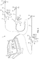
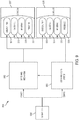
- FIG. 1 illustrates one form of a surgical system 10 comprising a generator 100 and various surgical instruments 104, 106, 108 usable therewith, where the surgical instrument 104 is an ultrasonic surgical instrument, the surgical instrument 106 is an RF electrosurgical instrument 106, and the multifunction surgical instrument 108 is a combination ultrasonic/RF electrosurgical instrument.
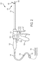
- FIG. 2 is a diagram of the multifunction surgical instrument 108 shown in FIG. 1 .
- the generator 100 is configurable for use with a variety of surgical instruments.
- the generator 100 may be configurable for use with different surgical instruments of different types including, for example, ultrasonic surgical instruments 104, RF electrosurgical instruments 106, and multifunction surgical instruments 108 that integrate RF and ultrasonic energies delivered simultaneously from the generator 100.
- the generator 100 is shown separate from the surgical instruments 104, 106, 108 in one form, the generator 100 may be formed integrally with any of the surgical instruments 104, 106, 108 to form a unitary surgical system.
- the generator 100 comprises an input device 110 located on a front panel of the generator 100 console.
- the input device 110 may comprise any suitable device that generates signals suitable for programming the operation of the generator 100.
- FIG. 1 illustrates a generator 100 configured to drive multiple surgical instruments 104, 106, 108.
- the first surgical instrument 104 is an ultrasonic surgical instrument 104 and comprises a handpiece 105 (HP), an ultrasonic transducer 120, a shaft 126, and an end effector 122.
- the end effector 122 comprises an ultrasonic blade 128 acoustically coupled to the ultrasonic transducer 120 and a clamp arm 140.
- the handpiece 105 comprises a trigger 143 to operate the clamp arm 140 and a combination of the toggle buttons 134a, 134b, 134c to energize and drive the ultrasonic blade 128 or other function.
- the toggle buttons 134a, 134b, 134c can be configured to energize the ultrasonic transducer 120 with the generator 100.
- the generator 100 also is configured to drive a second surgical instrument 106.
- the second surgical instrument 106 is an RF electrosurgical instrument and comprises a handpiece 107 (HP), a shaft 127, and an end effector 124.
- the end effector 124 comprises electrodes in the clamp arms 142a, 142b and return through an electrical conductor portion of the shaft 127.
- the electrodes are coupled to and energized by a bipolar energy source within the generator 100.
- the handpiece 107 comprises a trigger 145 to operate the clamp arms 142a, 142b and an energy button 135 to actuate an energy switch to energize the electrodes in the end effector 124.
- the generator 100 also is configured to drive a multifunction surgical instrument 108.
- the multifunction surgical instrument 108 comprises a handpiece 109 (HP), a shaft 129, and an end effector 125.
- the end effector comprises an ultrasonic blade 149 and a clamp arm 146.
- the ultrasonic blade 149 is acoustically coupled to the ultrasonic transducer 120.
- the handpiece 109 comprises a trigger 147 to operate the clamp arm 146 and a combination of the toggle buttons 137a, 137b, 137c to energize and drive the ultrasonic blade 149 or other function.
- the toggle buttons 137a, 137b, 137c can be configured to energize the ultrasonic transducer 120 with the generator 100 and energize the ultrasonic blade 149 with a bipolar energy source also contained within the generator 100.
- the generator 100 is configurable for use with a variety of surgical instruments.
- the generator 100 may be configurable for use with different surgical instruments of different types including, for example, the ultrasonic surgical instrument 104, the RF electrosurgical instrument 106, and the multifunction surgical instrument 108 that integrate RF and ultrasonic energies delivered simultaneously from the generator 100.
- the generator 100 is shown separate from the surgical instruments 104, 106, 108, in one form, the generator 100 may be formed integrally with any one of the surgical instruments 104, 106, 108 to form a unitary surgical system.
- the generator 100 comprises an input device 110 located on a front panel of the generator 100 console.
- the input device 110 may comprise any suitable device that generates signals suitable for programming the operation of the generator 100.
- the generator 100 also may comprise one or more output devices 112.
- the generator 100 is coupled to the multifunction surgical instrument 108.
- the generator 100 is coupled to the ultrasonic transducer 120 and electrodes located in the clamp arm 146 via a cable 144.
- the ultrasonic transducer 120 and a waveguide extending through a shaft 129 may collectively form an ultrasonic drive system driving an ultrasonic blade 149 of an end effector 125.
- the end effector 125 further may comprise a clamp arm 146 to clamp tissue located between the clamp arm 146 and the ultrasonic blade 149.
- the clamp arm 146 comprises one or more than one an electrode coupled to the a pole of the generator 100 (e.g., a positive pole).
- the ultrasonic blade 149 forms the second pole (e.g., the negative pole) and is also coupled to the generator 100.
- RF energy is applied to the electrode(s) in the clamp arm 146, through the tissue located between the clamp arm 146 and the ultrasonic blade 149, and through the ultrasonic blade 149 back to the generator 100 via the cable 144.
- the generator 100 may be configured to produce a drive signal of a particular voltage, current, and/or frequency output signal that can be varied or otherwise modified with high resolution, accuracy, and repeatability suitable for driving an ultrasonic transducer 120 and applying RF energy to tissue.
- the multifunction surgical instrument 108 may comprise any combination of the toggle buttons 137a, 137b, 134c.
- the multifunction surgical instrument 108 could be configured to have only two toggle buttons: a toggle button 137a for producing maximum ultrasonic energy output and a toggle button 137b for producing a pulsed output at either the maximum or less than maximum power level.
- the drive signal output configuration of the generator 100 could be 5 continuous signals and 5 or 4 or 3 or 2 or 1 pulsed signals.
- the specific drive signal configuration may be controlled based upon, for example, a non-volatile memory such as an electrically erasable programmable read only memory (EEPROM) settings in the generator 100 and/or user power level selection(s).
- EEPROM electrically erasable programmable read only memory
- a two-position switch may be provided as an alternative to a toggle button 137c.
- the multifunction surgical instrument 108 may include a toggle button 137a for producing a continuous output at a maximum power level and a two-position toggle button 137b. In a first detented position, toggle button 137b may produce a continuous output at a less than maximum power level, and in a second detented position the toggle button 137b may produce a pulsed output ( e.g ., at either a maximum or less than maximum power level, depending upon the EEPROM settings). Any one of the buttons 137a, 137b, 137c may be configured to activate RF energy and apply the RF energy to the end effector 125.
- forms of the generator 100 may enable communication with instrument-based data circuits.
- the generator 100 may be configured to communicate with a first data circuit 136 and/or a second data circuit 138.
- the first data circuit 136 may indicate a burn-in frequency slope, as described herein.
- any type of information may be communicated to second data circuit for storage therein via a data circuit interface (e.g ., using a logic device). Such information may comprise, for example, an updated number of operations in which the instrument has been used and/or dates and/or times of its usage.
- the second data circuit may transmit data acquired by one or more sensors (e.g ., an instrument-based temperature sensor).
- the second data circuit may receive data from the generator 100 and provide an indication to a user (e.g ., a light emitting diode (LED) indication or other visible indication) based on the received data.
- the second data circuit 138 may be implemented in a many similar to that of the first data circuit 136 described herein.
- An instrument interface circuit may comprise a second data circuit interface to enable this communication.
- the second data circuit interface may comprise a tri-state digital interface, although other interfaces also may be used.
- the second data circuit may generally be any circuit for transmitting and/or receiving data.
- the second data circuit may store information pertaining to the particular surgical instrument 104, 106, 108 with which it is associated. Such information may include, for example, a model number, a serial number, a number of operations in which the surgical instrument 104, 106, 108 has been used, and/or any other type of information.
- the second data circuit 138 may store information about the electrical and/or ultrasonic properties of an associated ultrasonic transducer 120, end effector 125, ultrasonic energy drive system, or RF electrosurgical energy drive system.
- Various processes and techniques described herein may be executed by a generator. It will be appreciated, however, that in certain example forms, all or a part of these processes and techniques may be performed by internal logic 139 located in the multifunction surgical instrument 108.
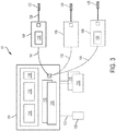
- FIG. 3 is a diagram of the surgical system 10 of FIG. 1 .
- the generator 100 may comprise several separate functional elements, such as modules and/or blocks. Different functional elements or modules may be configured for driving the different kinds of surgical instruments 104, 106, 108.
- an ultrasonic drive circuit 114 may drive ultrasonic devices such as the surgical instrument 104 via a cable 141.
- An electrosurgery/RF drive circuit 116 may drive the RF electrosurgical instrument 106 via a cable 133.
- the respective drive circuits 114, 116, 118 may be combined as a combined RF/ultrasonic drive circuit 118 to generate both respective drive signals for driving multifunction surgical instruments 108 via a cable 144.
- the ultrasonic drive circuit 114 and/or the electrosurgery/RF drive circuit 116 each may be formed integrally or externally with the generator 100.
- one or more of the drive circuits 114, 116, 118 may be provided as a separate circuit module electrically coupled to the generator 100.
- the drive circuits 114, 116, 118 are shown in phantom to illustrate this option.
- the electrosurgery/RF drive circuit 116 may be formed integrally with the ultrasonic drive circuit 114, or vice versa.
- the generator 100 may be omitted entirely and the drive circuits 114, 116, 118 may be executed by processors or other hardware within the respective surgical instruments 104, 106, 108.
- the electrical outputs of the ultrasonic drive circuit 114 and the electrosurgery/RF drive circuit 116 may be combined into a single electrical signal capable of driving the multifunction surgical instrument 108 simultaneously with electrosurgical RF and ultrasonic energies.
- This single electrical drive signal may be produced by the combination drive circuit 118.
- the multifunction surgical instrument 108 comprises an ultrasonic transducer 120 coupled to an ultrasonic blade and one or more electrodes in the end effector 125 to receive ultrasonic and electrosurgical RF energy.
- the multifunction surgical instrument 108 comprises signal processing components to split the combined RF/ultrasonic energy signal such that the RF signal can be delivered to the electrodes in the end effector 125 and the ultrasonic signal can be delivered to the ultrasonic transducer 120.
- the ultrasonic drive circuit 114 may produce a drive signal or signals of particular voltages, currents, and frequencies, e.g ., 55,500 cycles per second (Hz).
- the drive signal or signals may be provided to the ultrasonic surgical instrument 104, and specifically to the ultrasonic transducer 120, which may operate, for example, as described above.
- the ultrasonic transducer 120 and a waveguide extending through the shaft 126 may collectively form an ultrasonic drive system driving an ultrasonic blade 128 of an end effector 122.
- the generator 100 may be configured to produce a drive signal of a particular voltage, current, and/or frequency output signal that can be stepped or otherwise modified with high resolution, accuracy, and repeatability.
- the generator 100 may be activated to provide the drive signal to the ultrasonic transducer 120 in any suitable manner.
- the generator 100 may comprise a foot switch 130 coupled to the generator 100 via a foot switch cable 132.
- a clinician may activate the ultrasonic transducer 120 by depressing the foot switch 130.
- some forms of the ultrasonic surgical instrument 104 may utilize one or more switches positioned on the handpiece that, when activated, may cause the generator 100 to activate the ultrasonic transducer 120.
- the one or more switches may comprise a pair of toggle buttons 137a, 137b ( FIG. 2 ), for example, to determine an operating mode of the ultrasonic surgical instrument 104.
- the generator 100 may provide a maximum drive signal to the ultrasonic transducer 120, causing it to produce maximum ultrasonic energy output.
- Depressing toggle button 137b may cause the generator 100 to provide a user-selectable drive signal to the ultrasonic transducer 120, causing it to produce less than the maximum ultrasonic energy output.
- the one or more switches may comprise a toggle button 137c that, when depressed, causes the generator 100 to provide a pulsed output.
- the pulses may be provided at any suitable frequency and grouping, for example.
- the power level of the pulses may be the power levels associated with toggle buttons 137a, 137b (maximum, less than maximum), for example.
- the ultrasonic surgical instrument 104 and/or the multifunction surgical instrument 108 may comprise any combination of the toggle buttons 137a, 137b, 137c.
- the multifunction surgical instrument 108 could be configured to have only two toggle buttons: a toggle button 137a for producing maximum ultrasonic energy output and a toggle button 137c for producing a pulsed output at either the maximum or less than maximum power level.
- the drive signal output configuration of the generator 100 could be 5 continuous signals and 5 or 4 or 3 or 2 or 1 pulsed signals.
- the specific drive signal configuration may be controlled based upon, for example, EEPROM settings in the generator 100 and/or user power level selection(s).
- a two-position switch may be provided as an alternative to a toggle button 137c.
- the ultrasonic surgical instrument 104 may include a toggle button 137a for producing a continuous output at a maximum power level and a two-position toggle button 137b. In a first detented position, toggle button 137b may produce a continuous output at a less than maximum power level, and in a second detented position the toggle button 137b may produce a pulsed output ( e.g ., at either a maximum or less than maximum power level, depending upon the EEPROM settings).
- the electrosurgery/RF drive circuit 116 may generate a drive signal or signals with output power sufficient to perform bipolar electrosurgery using RF energy.
- the drive signal may be provided, for example, to electrodes located in the end effector 124 of the RF electrosurgical instrument 106, for example.
- the generator 100 may be configured for therapeutic purposes by applying electrical energy to the tissue sufficient for treating the tissue (e.g ., coagulation, cauterization, tissue welding).
- the generator 100 may be configured for sub-therapeutic purposes by applying electrical energy to the tissue for monitoring parameters of the tissue during a procedure.
- the combination drive circuit 118 may be configured to drive both ultrasonic and RF electrosurgical energies.
- the ultrasonic and RF electrosurgical energies may be delivered though separate output ports of the generator 100 as separate signals or though a single port of the generator 100 as a single signal that is a combination of the ultrasonic and RF electrosurgical energies. In the latter case, the single signal can be separated by circuits located in the surgical instruments 104, 106, 108.
- the surgical instruments 104, 106, 108 additionally or alternatively may comprise a switch to indicate a position of a jaw closure trigger for operating jaws of the end effector 122, 124, 125.
- the generator 100 may be activated based on the position of the jaw closure trigger, ( e.g. , as the clinician depresses the jaw closure trigger to close the jaws, ultrasonic energy may be applied).
- the generator 100 may comprise an input device 110 ( FIG. 1 ) located, for example, on a front panel of the generator 100 console.
- the input device 110 may comprise any suitable device that generates signals suitable for programming the operation of the generator 100. In operation, the user can program or otherwise control operation of the generator 100 using the input device 110.
- the input device 110 may comprise any suitable device that generates signals that can be used by the generator (e.g ., by one or more processors contained in the generator) to control the operation of the generator 100 (e.g ., operation of the ultrasonic drive circuit 114, electrosurgery/RF drive circuit 116, combined RF/ultrasonic drive circuit118).
- the input device 110 includes one or more of buttons, switches, thumbwheels, keyboard, keypad, touch screen monitor, pointing device, remote connection to a general purpose or dedicated computer.
- the input device 110 may comprise a suitable user interface, such as one or more user interface screens displayed on a touch screen monitor, for example. Accordingly, by way of the input device 110, the user can set or program various operating parameters of the generator, such as, for example, current (I), voltage (V), frequency (f), and/or period (T) of a drive signal or signals generated by the ultrasonic drive circuit 114 and/or electrosurgery/RF drive circuit 116.
- the generator 100 also may comprise an output device 112 ( FIG. 1 ), such as an output indicator, located, for example, on a front panel of the generator 100 console.
- the output device 112 includes one or more devices for providing a sensory feedback to a user.
- Such devices may comprise, for example, visual feedback devices (e.g ., a visual feedback device may comprise incandescent lamps, LEDs, graphical user interface, display, analog indicator, digital indicator, bar graph display, digital alphanumeric display, liquid crystal display (LCD) screen, light emitting diode (LED) indicators), audio feedback devices (e.g ., an audio feedback device may comprise speaker, buzzer, audible, computer generated tone, computerized speech, voice user interface (VUI) to interact with computers through a voice/speech platform), or tactile feedback devices (e.g ., a tactile feedback device comprises any type of vibratory feedback, haptic actuator).
- visual feedback devices e.g ., a visual feedback device may comprise incandescent lamps, LEDs,
- modules and/or blocks of the generator 100 may be described by way of example, it can be appreciated that a greater or lesser number of modules and/or blocks may be used and still fall within the scope of the forms.
- various forms may be described in terms of modules and/or blocks to facilitate description, such modules and/or blocks may be implemented by one or more hardware components, e.g ., processors, Digital Signal Processors (DSPs), Programmable Logic Devices (PLDs), Application Specific Integrated Circuits (ASICs), circuits, registers and/or software components, e.g ., programs, subroutines, logic and/or combinations of hardware and software components.
- the various modules described herein may be implemented utilizing similar hardware positioned within the surgical instruments 104, 106, 108 ( i.e., the external generator 100 may be omitted).
- the ultrasonic drive circuit 114, electrosurgery/RF drive circuit 116, and/or the combination drive circuit 118 may comprise one or more embedded applications implemented as firmware, software, hardware, or any combination thereof.
- the drive circuits 114, 116, 118 may comprise various executable modules such as software, programs, data, drivers, application program interfaces (APIs), and so forth.
- the firmware may be stored in nonvolatile memory (NVM), such as in bit masked read-only memory (ROM) or flash memory. In various implementations, storing the firmware in ROM may preserve flash memory.
- the NVM may comprise other types of memory including, for example, programmable ROM (PROM), erasable programmable ROM (EPROM), EEPROM, or battery backed random-access memory (RAM) such as dynamic RAM (DRAM), Double-Data-Rate DRAM (DDRAM), and/or synchronous DRAM (SDRAM).
- PROM programmable ROM
- EPROM erasable programmable ROM
- RAM battery backed random-access memory
- DRAM dynamic RAM
- DDRAM Double-Data-Rate DRAM
- SDRAM synchronous DRAM
- the drive circuits 114, 116, 118 comprise a hardware component implemented as a processor for executing program instructions for monitoring various measurable characteristics of the surgical instruments 104, 106, 108 and generating a corresponding output control signals for operating the surgical instruments 104, 106, 108.
- the output control signal may drive the ultrasonic transducer 120 in cutting and/or coagulation operating modes. Electrical characteristics of the multifunction surgical instrument 108 and/or tissue may be measured and used to control operational aspects of the generator 100 and/or provided as feedback to the user.
- the output control signal may supply electrical energy (e.g ., RF energy) to the end effector 125 in cutting, coagulation and/or desiccation modes.
- electrical energy e.g ., RF energy
- Electrical characteristics of the multifunction surgical instrument 108 and/or tissue may be measured and used to control operational aspects of the generator 100 and/or provide feedback to the user.
- the hardware component may be implemented as a DSP, PLD, ASIC, circuits, and/or registers.
- the processor may be configured to store and execute computer software program instructions to generate the output signals for driving various components of the surgical instruments 104, 106, 108, such as the ultrasonic transducer 120 and the end effectors 122, 124, 125.
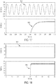
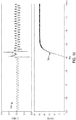
- FIG. 4 illustrates an equivalent circuit 150 of an ultrasonic transducer, such as the ultrasonic transducer 120, according to one form.
- the equivalent circuit 150 comprises a first "motional" branch having a serially connected inductance L s , resistance R s and capacitance C s that define the electromechanical properties of the resonator, and a second capacitive branch having a static capacitance C o .
- Drive current I g may be received from a generator at a drive voltage V g , with motional current I m flowing through the first branch and current I g - I m flowing through the capacitive branch.
- Control of the electromechanical properties of the ultrasonic transducer may be achieved by suitably controlling I g and V g .
- conventional generator architectures may include a tuning inductor L t (shown in phantom in FIG. 4 ) for tuning out in a parallel resonance circuit the static capacitance Co at a resonant frequency so that substantially all of generator's current output I g flows through the motional branch.
- control of the motional branch current I m is achieved by controlling the generator current output I g .
- the tuning inductor L t is specific to the static capacitance C o of an ultrasonic transducer, however, and a different ultrasonic transducer having a different static capacitance requires a different tuning inductor L t .
- the tuning inductor L t is matched to the nominal value of the static capacitance Co at a single resonant frequency, accurate control of the motional branch current I m is assured only at that frequency, and as frequency shifts down with transducer temperature, accurate control of the motional branch current is compromised.
- Forms of the generator 100 do not rely on a tuning inductor L t to monitor the motional branch current I m . Instead, the generator 100 may use the measured value of the static capacitance C o in between applications of power for a specific ultrasonic surgical instrument 104 (along with drive signal voltage and current feedback data) to determine values of the motional branch current I m on a dynamic and ongoing basis ( e.g. , in real-time). Such forms of the generator 100 are therefore able to provide virtual tuning to simulate a system that is tuned or resonant with any value of static capacitance C o at any frequency, and not just at single resonant frequency dictated by a nominal value of the static capacitance C o .
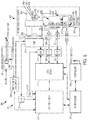
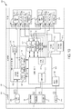
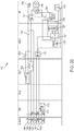
- FIG. 5 is a simplified block diagram of a generator 200, which is one form of the generator 100 ( FIGS. 1-3 ).
- the generator 200 is configured to provide inductorless tuning as described above, among other benefits. Additional details of the generator 200 are described in commonly assigned and contemporaneously filed U.S. Patent No. 9,060,775 , titled SURGICAL GENERATOR FOR ULTRASONIC AND ELECTROSURGICAL DEVICES.
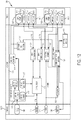
- the generator 200 may comprise a patient isolated stage 202 in communication with a non-isolated stage 204 via a power transformer 206.
- a secondary winding 208 of the power transformer 206 is contained in the isolated stage 202 and may comprise a tapped configuration (e.g ., a center-tapped or a non-center-tapped configuration) to define drive signal outputs 210a, 210b, 210c for delivering drive signals to different surgical instruments, such as, for example, an ultrasonic surgical instrument 104, an RF electrosurgical instrument 106, and a multifunction surgical instrument 108.
- a tapped configuration e.g ., a center-tapped or a non-center-tapped configuration
- drive signal outputs 210a, 210c may output an ultrasonic drive signal (e.g ., a 420V root-mean-square [RMS] drive signal) to an ultrasonic surgical instrument 104, and drive signal outputs 210b, 210c may output an electrosurgical drive signal (e.g ., a 100V RMS drive signal) to an RF electrosurgical instrument 106, with the drive signal output 2160b corresponding to the center tap of the power transformer 206.
- an ultrasonic drive signal e.g ., a 420V root-mean-square [RMS] drive signal
- electrosurgical drive signal e.g a 100V RMS drive signal
- the ultrasonic and electrosurgical drive signals may be provided simultaneously to distinct surgical instruments and/or to a single surgical instrument having the capability to deliver both ultrasonic and electrosurgical energy to tissue, such as the multifunction surgical instrument 108 ( FIGS. 1-3 ).
- the electrosurgical signal provided either to a dedicated electrosurgical instrument and/or to a combined multifunction ultrasonic/electrosurgical instrument may be either a therapeutic or sub-therapeutic level signal where the sub-therapeutic signal can be used, for example, to monitor tissue or instrument conditions and provide feedback to the generator.
- the ultrasonic and RF signals can be delivered separately or simultaneously from a generator with a single output port in order to provide the desired output signal to the surgical instrument, as will be discussed in more detail below.
- the generator can combine the ultrasonic and electrosurgical RF energies and deliver the combined energies to the multifunction ultrasonic/electrosurgical instrument.
- Bipolar electrodes can be placed on one or both jaws of the end effector. One jaw may be driven by ultrasonic energy in addition to electrosurgical RF energy, working simultaneously. The ultrasonic energy may be employed to dissect tissue while the electrosurgical RF energy may be employed for vessel sealing.
- the non-isolated stage 204 may comprise a power amplifier 212 having an output connected to a primary winding 214 of the power transformer 206.
- the power amplifier 212 may be comprise a push-pull amplifier.
- the non-isolated stage 204 may further comprise a logic device 216 for supplying a digital output to a digital-to-analog converter (DAC) circuit 218, which in turn supplies a corresponding analog signal to an input of the power amplifier 212.
- the logic device 216 may comprise a programmable gate array (PGA), a field programmable gate array (FPGA), programmable logic device (PLD), among other logic circuits, for example.
- the logic device 216 by virtue of controlling the input of the power amplifier 212 via the DAC circuit 218, may therefore control any of a number of parameters (e.g ., frequency, waveform shape, waveform amplitude) of drive signals appearing at the drive signal outputs 210a, 210b, 210c.
- the logic device 216 in conjunction with a processor (e.g ., a digital signal processor discussed below), may implement a number of digital signal processing (DSP)-based and/or other control algorithms to control parameters of the drive signals output by the generator 200.
- DSP digital signal processing
- Power may be supplied to a power rail of the power amplifier 212 by a switch-mode regulator 220, e.g., power converter.
- the switch-mode regulator 220 may comprise an adjustable buck regulator, for example.
- the non-isolated stage 204 may further comprise a first processor 222, which in one form may comprise a DSP processor such as an Analog Devices ADSP-21469 SHARC DSP, available from Analog Devices, Norwood, MA, for example, although in various forms any suitable processor may be employed.
- the DSP processor 222 may control operation of the switch-mode regulator 220 responsive to voltage feedback data received from the power amplifier 212 by the DSP processor 222 via an analog-to-digital converter (ADC) circuit 224.
- ADC analog-to-digital converter
- the DSP processor 222 may receive as input, via the ADC circuit 224, the waveform envelope of a signal (e.g ., an RF signal) being amplified by the power amplifier 212.
- the DSP processor 222 may then control the switch-mode regulator 220 (e.g ., via a pulse-width modulated (PWM) output) such that the rail voltage supplied to the power amplifier 212 tracks the waveform envelope of the amplified signal.
- PWM pulse-width modulated
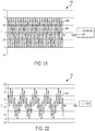
- the logic device 216 in conjunction with the DSP processor 222, may implement a digital synthesis circuit such as a DDS (see e.g., FIGS. 13, 14 ) control scheme to control the waveform shape, frequency and/or amplitude of drive signals output by the generator 200.
- the logic device 216 may implement a DDS control algorithm by recalling waveform samples stored in a dynamically-updated lookup table (LUT), such as a RAM LUT, which may be embedded in an FPGA.
- LUT dynamically-updated lookup table
- This control algorithm is particularly useful for ultrasonic applications in which an ultrasonic transducer, such as the ultrasonic transducer 120, may be driven by a clean sinusoidal current at its resonant frequency.
- minimizing or reducing the total distortion of the motional branch current may correspondingly minimize or reduce undesirable resonance effects.
- voltage and current feedback data based on the drive signal may be input into an algorithm, such as an error control algorithm implemented by the DSP processor 222, which compensates for distortion by suitably pre-distorting or modifying the waveform samples stored in the LUT on a dynamic, ongoing basis ( e.g ., in real-time).
- the amount or degree of pre-distortion applied to the LUT samples may be based on the error between a computed motional branch current and a desired current waveform shape, with the error being determined on a sample-by-sample basis.
- the pre-distorted LUT samples when processed through the drive circuit, may result in a motional branch drive signal having the desired waveform shape (e.g ., sinusoidal) for optimally driving the ultrasonic transducer.
- the LUT waveform samples will therefore not represent the desired waveform shape of the drive signal, but rather the waveform shape that is required to ultimately produce the desired waveform shape of the motional branch drive signal when distortion effects are taken into account.
- the non-isolated stage 204 may further comprise a first ADC circuit 226 and a second ADC circuit 228 coupled to the output of the power transformer 206 via respective isolation transformers 230, 232 for respectively sampling the voltage and current of drive signals output by the generator 200.
- the ADC circuits 226, 228 may be configured to sample at high speeds (e.g ., 80 mega samples per second [MSPS]) to enable oversampling of the drive signals.
- the sampling speed of the ADC circuits 226, 228 may enable approximately 200x (depending on frequency) oversampling of the drive signals.
- the sampling operations of the ADC circuit 226, 228 may be performed by a single ADC circuit receiving input voltage and current signals via a two-way multiplexer.
- the use of highspeed sampling in forms of the generator 200 may enable, among other things, calculation of the complex current flowing through the motional branch (which may be used in certain forms to implement direct digital synthesis (DDS) based waveform shape control described above), accurate digital filtering of the sampled signals, and calculation of real power consumption with a high degree of precision.
- DDS direct digital synthesis
- Voltage and current feedback data output by the ADC circuits 226, 228 may be received and processed (e.g ., first-in-first-out [FIFO] buffer, multiplexer, etc.) by the logic device 216 and stored in data memory for subsequent retrieval by, for example, the DSP processor 222.
- voltage and current feedback data may be used as input to an algorithm for pre-distorting or modifying LUT waveform samples on a dynamic and ongoing basis. In certain forms, this may require each stored voltage and current feedback data pair to be indexed based on, or otherwise associated with, a corresponding LUT sample that was output by the logic device 216 when the voltage and current feedback data pair was acquired. Synchronization of the LUT samples and the voltage and current feedback data in this manner contributes to the correct timing and stability of the pre-distortion algorithm.
- the voltage and current feedback data may be used to control the frequency and/or amplitude (e.g ., current amplitude) of the drive signals.
- voltage and current feedback data may be used to determine impedance phase.
- the frequency of the drive signal may then be controlled to minimize or reduce the difference between the determined impedance phase and an impedance phase setpoint ( e.g ., 0°), thereby minimizing or reducing the effects of harmonic distortion and correspondingly enhancing impedance phase measurement accuracy.
- the determination of phase impedance and a frequency control signal may be implemented in the DSP processor 222, for example, with the frequency control signal being supplied as input to a DDS control algorithm implemented by the logic device 216.
- the current feedback data may be monitored in order to maintain the current amplitude of the drive signal at a current amplitude setpoint.
- the current amplitude setpoint may be specified directly or determined indirectly based on specified voltage amplitude and power setpoints.
- control of the current amplitude may be implemented by control algorithm, such as, for example, a proportional-integral-derivative (PID) control algorithm, in the DSP processor 222.
- PID proportional-integral-derivative
- Variables controlled by the control algorithm to suitably control the current amplitude of the drive signal may include, for example, the scaling of the LUT waveform samples stored in the logic device 216 and/or the full-scale output voltage of the DAC circuit 218 (which supplies the input to the power amplifier 212) via a DAC circuit 234.
- the non-isolated stage 204 may further comprise a second processor 236 for providing, among other things user interface (Ul) functionality.
- the UI processor 236 may comprise an Atmel AT91SAM9263 processor having an ARM 926EJ-S core, available from Atmel Corporation, San Jose, CA, for example.
- Examples of UI functionality supported by the UI processor 236 may include audible and visual user feedback, communication with peripheral devices (e.g ., via a Universal Serial Bus [USB] interface), communication with the foot switch 130, communication with an input device 110 (e.g ., a touch screen display) and communication with an output device 112 (e.g ., a speaker), as shown in FIGS. 1 and 3 .
- the UI processor 236 may communicate with the DSP processor 222 and the logic device 216 ( e.g. , via serial peripheral interface [SPI] buses). Although the UI processor 236 may primarily support UI functionality, it may also coordinate with the DSP processor 222 to implement hazard mitigation in certain forms. For example, the UI processor 236 may be programmed to monitor various aspects of user input and/or other inputs (e.g ., touch screen inputs, foot switch 130 inputs as shown in FIG. 3 , temperature sensor inputs) and may disable the drive output of the generator 200 when an erroneous condition is detected.
- SPI serial peripheral interface
- both the DSP processor 222 and the UI processor 236, may determine and monitor the operating state of the generator 200.
- the operating state of the generator 200 may dictate, for example, which control and/or diagnostic processes are implemented by the DSP processor 222.
- the operating state of the generator 200 may dictate, for example, which elements of a user interface (e.g ., display screens, sounds) are presented to a user.
- the respective DSP and UI processors 222, 236 may independently maintain the current operating state of the generator 200 and recognize and evaluate possible transitions out of the current operating state.
- the DSP processor 222 may function as the master in this relationship and determine when transitions between operating states are to occur.
- the UI processor 236 may be aware of valid transitions between operating states and may confirm if a particular transition is appropriate. For example, when the DSP processor 222 instructs the UI processor 236 to transition to a specific state, the UI processor 236 may verify that requested transition is valid. In the event that a requested transition between states is determined to be invalid by the UI processor 236, the UI processor 236 may cause the generator 200 to enter a failure mode.
- the non-isolated stage 204 may further comprise a controller 238 for monitoring input devices 110 (e.g ., a capacitive touch sensor used for turning the generator 200 on and off, a capacitive touch screen).
- the controller 238 may comprise at least one processor and/or other controller device in communication with the UI processor 236.
- the controller 238 may comprise a processor (e.g ., a Mega168 8-bit controller available from Atmel) configured to monitor user input provided via one or more capacitive touch sensors.
- the controller 238 may comprise a touch screen controller (e.g ., a QT5480 touch screen controller available from Atmel) to control and manage the acquisition of touch data from a capacitive touch screen.
- the controller 238 may continue to receive operating power (e.g ., via a line from a power supply of the generator 200, such as the power supply 254 discussed below). In this way, the controller 196 may continue to monitor an input device 110 (e.g ., a capacitive touch sensor located on a front panel of the generator 200) for turning the generator 200 on and off.
- the controller 238 may wake the power supply (e.g ., enable operation of one or more DC/DC voltage converters 256 of the power supply 254) if activation of the "on/off" input device 110 by a user is detected.
- the controller 238 may therefore initiate a sequence for transitioning the generator 200 to a "power on” state. Conversely, the controller 238 may initiate a sequence for transitioning the generator 200 to the power off state if activation of the "on/off" input device 110 is detected when the generator 200 is in the power on state. In certain forms, for example, the controller 238 may report activation of the "on/off" input device 110 to the UI processor 236, which in turn implements the necessary process sequence for transitioning the generator 200 to the power off state. In such forms, the controller 196 may have no independent ability for causing the removal of power from the generator 200 after its power on state has been established.
- the controller 238 may cause the generator 200 to provide audible or other sensory feedback for alerting the user that a power on or power off sequence has been initiated. Such an alert may be provided at the beginning of a power on or power off sequence and prior to the commencement of other processes associated with the sequence.
- the isolated stage 202 may comprise an instrument interface circuit 240 to, for example, provide a communication interface between a control circuit of a surgical instrument (e.g ., a control circuit comprising handpiece switches) and components of the non-isolated stage 204, such as, for example, the logic device 216, the DSP processor 222 and/or the UI processor 236.
- the instrument interface circuit 240 may exchange information with components of the non-isolated stage 204 via a communication link that maintains a suitable degree of electrical isolation between the isolated and non-isolated stages 202, 204, such as, for example, an infrared (IR)-based communication link.
- Power may be supplied to the instrument interface circuit 240 using, for example, a low-dropout voltage regulator powered by an isolation transformer driven from the non-isolated stage 204.
- the instrument interface circuit 240 may comprise a logic circuit 242 (e.g ., logic circuit, programmable logic circuit, PGA, FPGA, PLD) in communication with a signal conditioning circuit 244.
- the signal conditioning circuit 244 may be configured to receive a periodic signal from the logic circuit 242 (e.g ., a 2 kHz square wave) to generate a bipolar interrogation signal having an identical frequency.
- the interrogation signal may be generated, for example, using a bipolar current source fed by a differential amplifier.
- the interrogation signal may be communicated to a surgical instrument control circuit (e.g ., by using a conductive pair in a cable that connects the generator 200 to the surgical instrument) and monitored to determine a state or configuration of the control circuit.
- the control circuit may comprise a number of switches, resistors and/or diodes to modify one or more characteristics (e.g ., amplitude, rectification) of the interrogation signal such that a state or configuration of the control circuit is uniquely discernable based on the one or more characteristics.
- the signal conditioning circuit 244 may comprise an ADC circuit for generating samples of a voltage signal appearing across inputs of the control circuit resulting from passage of interrogation signal therethrough.
- the logic circuit 242 (or a component of the non-isolated stage 204) may then determine the state or configuration of the control circuit based on the ADC circuit samples.
- the instrument interface circuit 240 may comprise a first data circuit interface 246 to enable information exchange between the logic circuit 242 (or other element of the instrument interface circuit 240) and a first data circuit disposed in or otherwise associated with a surgical instrument.
- a first data circuit 136 FIG. 2
- the first data circuit 136 may be implemented in any suitable manner and may communicate with the generator according to any suitable protocol including, for example, as described herein with respect to the first data circuit 136.
- the first data circuit may comprise a non-volatile storage device, such as an EEPROM device.
- the first data circuit interface 246 may be implemented separately from the logic circuit 242 and comprise suitable circuitry (e.g ., discrete logic devices, a processor) to enable communication between the logic circuit 242 and the first data circuit. In other forms, the first data circuit interface 246 may be integral with the logic circuit 242.
- the first data circuit 136 * FIG. 2 may store information pertaining to the particular surgical instrument with which it is associated. Such information may include, for example, a model number, a serial number, a number of operations in which the surgical instrument has been used, and/or any other type of information. This information may be read by the instrument interface circuit 240 ( e.g ., by the logic circuit 242), transferred to a component of the non-isolated stage 204 ( e.g ., to logic device 216, DSP processor 222 and/or UI processor 236) for presentation to a user via an output device 112 ( FIGS. 1 and 3 ) and/or for controlling a function or operation of the generator 200.
- the instrument interface circuit 240 e.g ., by the logic circuit 242
- a component of the non-isolated stage 204 e.g ., to logic device 216, DSP processor 222 and/or UI processor 236
- FIGS. 1 and 3 an output device 112
- any type of information may be communicated to first data circuit 136 for storage therein via the first data circuit interface 246 (e.g ., using the logic circuit 242).
- Such information may comprise, for example, an updated number of operations in which the surgical instrument has been used and/or dates and/or times of its usage.
- a surgical instrument may be detachable from a handpiece (e.g ., the multifunction surgical instrument 108 may be detachable from the handpiece 109) to promote instrument interchangeability and/or disposability.
- conventional generators may be limited in their ability to recognize particular instrument configurations being used and to optimize control and diagnostic processes accordingly.
- the addition of readable data circuits to surgical instruments to address this issue is problematic from a compatibility standpoint, however. For example, designing a surgical instrument to remain backwardly compatible with generators that lack the requisite data reading functionality may be impractical due to, for example, differing signal schemes, design complexity, and cost.
- Forms of instruments discussed herein address these concerns by using data circuits that may be implemented in existing surgical instruments economically and with minimal design changes to preserve compatibility of the surgical instruments with current generator platforms.
- forms of the generator 200 may enable communication with instrument-based data circuits.
- the generator 200 may be configured to communicate with a second data circuit 138 ( FIG. 2 ) contained in an instrument ( e.g ., the multifunction surgical instrument 108 shown in FIG. 2 ).
- the second data circuit 138 may be implemented in a many similar to that of the first data circuit 136 ( FIG. 2 ) described herein.
- the instrument interface circuit 240 may comprise a second data circuit interface 248 to enable this communication.
- the second data circuit interface 248 may comprise a tri-state digital interface, although other interfaces may also be used.
- the second data circuit may generally be any circuit for transmitting and/or receiving data.
- the second data circuit may store information pertaining to the particular surgical instrument with which it is associated.
- information may include, for example, a model number, a serial number, a number of operations in which the surgical instrument has been used, and/or any other type of information.
- the second data circuit 138 may store information about the electrical and/or ultrasonic properties of an associated ultrasonic transducer 120, end effector 125, or ultrasonic drive system.
- the first data circuit 136 may indicate a burn-in frequency slope, as described herein.
- any type of information may be communicated to second data circuit for storage therein via the second data circuit interface 248 ( e.g ., using the logic circuit 242). Such information may comprise, for example, an updated number of operations in which the instrument has been used and/or dates and/or times of its usage.
- the second data circuit may transmit data acquired by one or more sensors (e.g ., an instrument-based temperature sensor).
- the second data circuit may receive data from the generator 200 and provide an indication to a user (e.g ., a light emitting diode [LED] indication or other visible indication) based on the received data.
- a user e.g ., a light emitting diode [LED] indication or other visible indication
- the second data circuit and the second data circuit interface 248 may be configured such that communication between the logic circuit 242 and the second data circuit can be effected without the need to provide additional conductors for this purpose (e.g ., dedicated conductors of a cable connecting a handpiece to the generator 200).
- information may be communicated to and from the second data circuit using a 1-wire bus communication scheme implemented on existing cabling, such as one of the conductors used transmit interrogation signals from the signal conditioning circuit 244 to a control circuit in a handpiece. In this way, design changes or modifications to the surgical instrument that might otherwise be necessary are minimized or reduced.
- the presence of a second data circuit may be "invisible" to generators that do not have the requisite data reading functionality, thus enabling backward compatibility of the surgical instrument.
- the isolated stage 202 may comprise at least one blocking capacitor 250-1 connected to the drive signal output 210b to prevent passage of DC current to a patient.
- a single blocking capacitor may be required to comply with medical regulations or standards, for example. While failure in single-capacitor designs is relatively uncommon, such failure may nonetheless have negative consequences.
- a second blocking capacitor 250-2 may be provided in series with the blocking capacitor 250-1, with current leakage from a point between the blocking capacitors 250-1, 250-2 being monitored by, for example, an ADC circuit 252 for sampling a voltage induced by leakage current. The samples may be received by the logic circuit 242, for example. Based changes in the leakage current (as indicated by the voltage samples in the form of FIG. 5 ), the generator 200 may determine when at least one of the blocking capacitors 250-1, 250-2 has failed. Accordingly, the form of FIG. 5 provides a benefit over single-capacitor designs having a single point of failure.
- the non-isolated stage 204 may comprise a power supply 254 for delivering DC power at a suitable voltage and current.
- the power supply may comprise, for example, a 400 W power supply for delivering a 48 VDC system voltage.
- the power supply 254 may further comprise one or more DC/DC voltage converters 256 for receiving the output of the power supply to generate DC outputs at the voltages and currents required by the various components of the generator 200.
- one or more of the DC/DC voltage converters 256 may receive an input from the controller 238 when activation of the "on/off" input device 110 by a user is detected by the controller 238 to enable operation of, or wake, the DC/DC voltage converters 256.
- FIG. 6 illustrates one form of a drive system 302 of a generator 300, which is one form of the generator 100 ( FIGS. 1-3 ).
- the generator 300 is configured to provide an ultrasonic electrical signal for driving an ultrasonic transducer (e.g., ultrasonic transducer 120 FIGS. 1-3 ), also referred to as a drive signal.
- the generator 300 is similar to and may be interchangeable with the generators 100, 200 ( FIGS. 1-3 and 5 ).
- the drive system 302 is flexible and can create an ultrasonic electrical drive signal 304 at a desired frequency and power level setting for driving the ultrasonic transducer 306.
- the generator 300 may comprise several separate functional elements, such as modules and/or blocks.
- modules and/or blocks may be described by way of example, it can be appreciated that a greater or lesser number of modules and/or blocks may be used and still fall within the scope of the forms.
- various forms may be described in terms of modules and/or blocks to facilitate description, such modules and/or blocks may be implemented by one or more hardware components, e.g ., processors, Digital Signal Processors (DSPs), Programmable Logic Devices (PLDs), Application Specific Integrated Circuits (ASICs), circuits, registers and/or software components, e.g ., programs, subroutines, logic and/or combinations of hardware and software components.
- DSPs Digital Signal Processors
- PLDs Programmable Logic Devices
- ASICs Application Specific Integrated Circuits
- the generator 300 drive system 302 may comprise one or more embedded applications implemented as firmware, software, hardware, or any combination thereof.
- the generator 300 drive system 302 may comprise various executable modules such as software, programs, data, drivers, application program interfaces (APIs), and so forth.
- the firmware may be stored in nonvolatile memory (NVM), such as in bit-masked read-only memory (ROM) or flash memory. In various implementations, storing the firmware in ROM may preserve flash memory.
- the NVM may comprise other types of memory including, for example, programmable ROM (PROM), erasable programmable ROM (EPROM), EEPROM, or battery backed random-access memory (RAM) such as dynamic RAM (DRAM), Double-Data-Rate DRAM (DDRAM), and/or synchronous DRAM (SDRAM).
- PROM programmable ROM
- EPROM erasable programmable ROM
- RAM battery backed random-access memory
- DRAM dynamic RAM
- DDRAM Double-Data-Rate DRAM
- SDRAM synchronous DRAM
- the generator 300 drive system 302 comprises a hardware component implemented as a processor 308 for executing program instructions for monitoring various measurable characteristics of the ultrasonic surgical instrument 104 ( FIG. 1 ) and generating an output signal for driving the ultrasonic transducer in cutting and/or coagulation operating modes.
- the generator 300 and the drive system 302 may comprise additional or fewer components and only a simplified version of the generator 300 and the drive system 302 are described herein for conciseness and clarity.
- the hardware component may be implemented as a DSP, PLD, ASIC, circuits, and/or registers.
- the processor 308 may be configured to store and execute computer software program instructions to generate the output signals for driving various components of the ultrasonic surgical instrument 104, such as a transducer, an end effector, and/or a blade.
- the processor 308 executes the methods in accordance with the described forms to generate an electrical signal output waveform comprising current (I), voltage (V), and/or frequency (f) for various time intervals or periods (T).
- the stepwise waveforms of the drive signals may be generated by forming a piecewise linear combination of constant functions over a plurality of time intervals created by stepping the generator 300 drive signals, e.g ., output drive current (I), voltage (V), and/or frequency (f).
- the time intervals or periods (T) may be predetermined ( e.g ., fixed and/or programmed by the user) or may be variable.
- Variable time intervals may be defined by setting the drive signal to a first value and maintaining the drive signal at that value until a change is detected in a monitored characteristic.
- monitored characteristics may comprise, for example, transducer impedance, tissue impedance, tissue heating, tissue transection, tissue coagulation, and the like.
- the ultrasonic drive signals generated by the generator 300 include, without limitation, ultrasonic drive signals capable of exciting the ultrasonic transducer 306 in various vibratory modes such as, for example, the primary longitudinal mode and harmonics thereof as well flexural and torsional vibratory modes.
- the executable modules comprise one or more algorithm(s) 310 stored in memory that when executed causes the processor 308 to generate an electrical signal output waveform comprising current (I), voltage (V), and/or frequency (f) for various time intervals or periods (T).
- the stepwise waveforms of the drive signals may be generated by forming a piecewise linear combination of constant functions over two or more time intervals created by stepping the output drive current (I), voltage (V), and/or frequency (f) of the generator 300.
- the drive signals may be generated either for predetermined fixed time intervals or periods (T) of time or variable time intervals or periods of time in accordance with the one or more algorithm(s) 310.
- the generator 100 outputs (e.g ., increases or decreases) the current (I), voltage (V), and/or frequency (f) up or down at a particular resolution for a predetermined period (T) or until a predetermined condition is detected, such as a change in a monitored characteristic (e.g ., transducer impedance, tissue impedance).
- a predetermined condition such as a change in a monitored characteristic (e.g ., transducer impedance, tissue impedance).
- the steps can change in programmed increments or decrements. If other steps are desired, the generator 300 can increase or decrease the step adaptively based on measured system characteristics.
- the user can program the operation of the generator 300 using the input device 312 located on the front panel of the generator 300 console.
- the input device 312 may comprise any suitable device that generates signals 314 that can be applied to the processor 308 to control the operation of the generator 300.
- the input device 312 includes buttons, switches, thumbwheels, keyboard, keypad, touch screen monitor, pointing device, remote connection to a general purpose or dedicated computer.
- the input device 312 may comprise a suitable user interface. Accordingly, by way of the input device 312, the user can set or program the current (I), voltage (V), frequency (f), and/or period (T) for programming the output of the generator 300.
- the processor 308 displays the selected power level by sending a signal on line 316 to an output indicator 318.
- the output indicator 318 may provide visual, audible, and/or tactile feedback to the surgeon to indicate the status of a surgical procedure, such as, for example, when tissue cutting and coagulating is complete based on a measured characteristic of the ultrasonic surgical instrument 104, e.g ., transducer impedance, tissue impedance, or other measurements as subsequently described.
- visual feedback comprises any type of visual indication device including incandescent lamps or LEDs, graphical user interface, display, analog indicator, digital indicator, bar graph display, digital alphanumeric display.
- audible feedback comprises any type of buzzer, computer generated tone, computerized speech, voice user interface (VUI) to interact with computers through a voice/speech platform.
- tactile feedback comprises any type of vibratory feedback provided through an instrument housing handle assembly.
- the processor 308 may be configured or programmed to generate a digital current signal 320 and a digital frequency signal 322. These digital signals 320, 322 are applied to a digital synthesis circuit such as the DDS circuit 324 (see e.g., FIGS. 13, 14 ) to adjust the amplitude and the frequency (f) of the ultrasonic electrical drive signal 304 to the transducer.
- the output of the DDS circuit 324 is applied to a power amplifier 326 whose output is applied to a transformer 328.
- the output of the transformer 328 is the ultrasonic electrical drive signal 304 applied to the ultrasonic transducer 306, which is coupled to a blade by way of a waveguide.
- the output of the DDS circuit 324 may be stored in one more memory circuits including volatile (RAM) and non-volatile (ROM) memory circuits.
- the generator 300 comprises one or more measurement modules or components that may be configured to monitor measurable characteristics of the ultrasonic instrument 104 ( FIGS. 1 , 2 ) or the multifunction surgical instrument 108 ( FIGS.1-3 ).
- the processor 308 may be employed to monitor and calculate system characteristics. As shown, the processor 308 measures the impedance Z of the transducer by monitoring the current supplied to the ultrasonic transducer 306 and the voltage applied to the transducer.
- a current sense circuit 330 is employed to sense the current flowing through the transducer and a voltage sense circuit 332 is employed to sense the output voltage applied to the ultrasonic transducer 306.
- the processor 308 receives the digital output 338 of the ADC circuit 336 and calculates the transducer impedance Z based on the measured values of current and voltage.
- the processor 308 adjusts the ultrasonic electrical drive signal 304 such that it can generate a desired power versus load curve.
- the processor 308 can step the ultrasonic electrical drive signal 304, e.g ., the current or frequency, in any suitable increment or decrement in response to the transducer impedance Z.
- FIG. 7 illustrates one aspect of a drive system 402 of the generator 400, which is one form of the generator 100 ( FIGS. 1-3 ).
- the user can program the operation of the generator 400 using the input device 412 located on the front panel of the generator 400 console.
- the input device 412 may comprise any suitable device that generates signals 414 that can be applied to the processor 408 to control the operation of the generator 400.
- the input device 412 includes buttons, switches, thumbwheels, keyboard, keypad, touch screen monitor, pointing device, remote connection to a general purpose or dedicated computer.
- the input device 412 may comprise a suitable user interface.
- the user can set or program the current (I), voltage (V), frequency (f), and/or period (T) for programming the output of the generator 400.
- the processor 408 then displays the selected power level by sending a signal on line 416 to an output indicator 418.
- the generator 400 comprises a tissue impedance module 442.
- the drive system 402 is configured to generate electrical drive signal 404 to drive the ultrasonic transducer 406.
- the tissue impedance module 442 may be configured to measure the impedance Zt of tissue grasped between the blade 440 and the clamp arm assembly 444.
- the tissue impedance module 442 comprises an RF oscillator 446, an RF voltage sensing circuit 448, and an RF current sensing circuit 450.
- the RF voltage and RF current sensing circuits 448, 450 respond to the RF voltage Vrf applied to the blade 440 electrode and the RF current irf flowing through the blade 440 electrode, the tissue, and the conductive portion of the clamp arm assembly 444.
- the sensed voltage Vrf and current Irf are converted to digital form by the ADC circuit 436 via the analog multiplexer 434.
- the processor 408 receives the digital output 438 of the ADC circuit 436 and determines the tissue impedance Zt by calculating the ratio of the RF voltage Vrf to current Irf measured by the RF voltage sense circuit 448 and the RF current sense circuit 450.
- the transection of the inner muscle layer and the tissue may be detected by sensing the tissue impedance Zt. Accordingly, detection of the tissue impedance Zt may be integrated with an automated process for separating the inner muscle layer from the outer adventitia layer prior to transecting the tissue without causing a significant amount of heating, which normally occurs at resonance.
- the RF voltage Vrf applied to the blade 440 electrode and the RF current Irf flowing through the blade 440 electrode, the tissue, and the conductive portion of the clamp arm assembly 451 are suitable for vessel sealing and//or dissecting.
- the RF power output of the generator 400 can be selected for non-therapeutic functions such as tissue impedance measurements as well as therapeutic functions such as vessel sealing and/or dissection. It will be appreciated, that in the context of the present disclosure, the ultrasonic and the RF electrosurgical energies can be supplied by the generator either individually or simultaneously.
- feedback is provided by the output indicator 418 shown in FIGS. 6 and 7 .
- the output indicator 418 is particularly useful in applications where the tissue being manipulated by the end effector is out of the user's field of view and the user cannot see when a change of state occurs in the tissue.
- the output indicator 418 communicates to the user that a change in tissue state has occurred.
- the output indicator 418 may be configured to provide various types of feedback to the user including, without limitation, visual, audible, and/or tactile feedback to indicate to the user ( e.g ., surgeon, clinician) that the tissue has undergone a change of state or condition of the tissue.
- visual feedback comprises any type of visual indication device including incandescent lamps or LEDs, graphical user interface, display, analog indicator, digital indicator, bar graph display, digital alphanumeric display.
- audible feedback comprises any type of buzzer, computer generated tone, computerized speech, VUI to interact with computers through a voice/speech platform.
- tactile feedback comprises any type of vibratory feedback provided through the instrument housing handle assembly. The change of state of the tissue may be determined based on transducer and tissue impedance measurements as previously described, or based on voltage, current, and frequency measurements.
- the processor 408 may be configured or programmed to generate a digital current signal 420 and a digital frequency signal 422. These digital signals 420, 422 are applied to a digital synthesis circuit such as the DDS circuit 424 (see e.g., FIGS. 13, 14 ) to adjust the amplitude and the frequency (f) of the electrical drive signal 404 to the ultrasonic transducer 406.
- the output of the DDS circuit 424 is applied to a power amplifier 426 whose output is applied to a transformer 428.
- the output of the transformer 428 is the electrical drive signal 404 applied to the ultrasonic transducer 406, which is coupled to a blade by way of a waveguide.
- the output of the DDS circuit 424 may be stored in one more memory circuits including volatile (RAM) and non-volatile (ROM) memory circuits.
- the generator 400 comprises one or more measurement modules or components that may be configured to monitor measurable characteristics of the ultrasonic instrument 104 ( FIGS. 1 , 3 ) or the multifunction electrosurgical/ultrasonic instrument 108 ( FIGS.1-3 ).
- the processor 408 may be employed to monitor and calculate system characteristics. As shown, the processor 408 measures the impedance Z of the transducer by monitoring the current supplied to the ultrasonic transducer 406 and the voltage applied to the transducer.
- a current sense circuit 430 is employed to sense the current flowing through the transducer and a voltage sense circuit 432 is employed to sense the output voltage applied to the ultrasonic transducer 406.
- the processor 408 receives the digital output 438 of the ADC circuit 436 and calculates the transducer impedance Z based on the measured values of current and voltage.
- the processor 308 adjusts the electrical drive signal 404 such that it can generate a desired power versus load curve.
- the processor 408 can step the ultrasonic electrical drive signal 404, e.g., the current or frequency, in any suitable increment or decrement in response to the transducer impedance Z.
- the various executable instructions or modules comprising computer readable instructions can be executed by the processor 308, 408 portion of the generator 300, 400.
- the operations described with respect to the algorithms may be implemented as one or more software components, e.g ., programs, subroutines, logic; one or more hardware components, e.g ., processors, DSPs, PLDs, ASICs, circuits, registers; and/or combinations of software and hardware.
- the executable instructions to perform the algorithms may be stored in memory.
- the instructions When executed, the instructions cause the processor 308, 408 to determine a change in tissue state provide feedback to the user by way of the output indicator 318, 418.
- the processor 308, 408 monitors and evaluates the voltage, current, and/or frequency signal samples available from the generator 300, 400 and according to the evaluation of such signal samples determines whether a change in tissue state has occurred.
- a change in tissue state may be determined based on the type of ultrasonic instrument and the power level that the instrument is energized at.
- the operational mode of the surgical instruments 104, 106, 108 may be controlled by the user or may be automatically or semi-automatically controlled.
- FIG. 8 illustrates an example of a generator 500, which is one form of the generator 100 ( FIGS. 1-3 ).
- the generator 500 is configured to deliver multiple energy modalities to a surgical instrument.
- the generator 500 includes functionalities of the generators 200, 300, 400 shown in FIGS. 5-7 .
- the generator 500 provides RF and ultrasonic signals for delivering energy to a surgical instrument.
- the RF and ultrasonic signals may be provided alone or in combination and may be provided simultaneously.
- At least one generator output can deliver multiple energy modalities (e.g., ultrasonic, bipolar or monopolar RF, irreversible and/or reversible electroporation, and/or microwave energy, among others) through a single port and these signals can be delivered separately or simultaneously to the end effector to treat tissue.
- the generator 500 comprises a processor 502 coupled to a waveform generator 504.
- the processor 502 and waveform generator 504 are configured to generate a variety of signal waveforms based on information stored in a memory coupled to the processor 502, not shown for clarity of disclosure.
- the digital information associated with a waveform is provided to the waveform generator 504 which includes one or more DAC circuits to convert the digital input into an analog output.
- the analog output is fed to an amplifier 1106 for signal conditioning and amplification.
- the conditioned and amplified output of the amplifier 506 is coupled to a power transformer 508.
- the signals are coupled across the power transformer 508 to the secondary side, which is in the patient isolation side.
- a first signal of a first energy modality is provided to the surgical instrument between the terminals labeled ENERGY1 and RETURN.
- a second signal of a second energy modality is coupled across a capacitor 510 and is provided to the surgical instrument between the terminals labeled ENERGY2 and RETURN.
- n may be used to designate that up to n ENERGYn terminals may be provided, where n is a positive integer greater than 1. It also will be appreciated that up to "n” return paths RETURNn may be provided without departing from the scope of the present disclosure.
- a first voltage sensing circuit 512 is coupled across the terminals labeled ENERGY1 and the RETURN path to measure the output voltage therebetween.
- a second voltage sensing circuit 524 is coupled across the terminals labeled ENERGY2 and the RETURN path to measure the output voltage therebetween.
- a current sensing circuit 514 is disposed in series with the RETURN leg of the secondary side of the power transformer 508 as shown to measure the output current for either energy modality. If different return paths are provided for each energy modality, then a separate current sensing circuit should be provided in each return leg.
- the outputs of the first and second voltage sensing circuits 512, 524 are provided to respective isolation transformers 516, 522 and the output of the current sensing circuit 514 is provided to another isolation transformer 518.
- the outputs of the isolation transformers 516, 518, 522 in the on the primary side of the power transformer 508 (non-patient-isolated side) are provided to a one or more ADC circuit 526.
- the digitized output of the ADC circuit 526 is provided to the processor 502 for further processing and computation.
- the output voltages and output current feedback information can be employed to adjust the output voltage and current provided to the surgical instrument and to compute output impedance, among other parameters.
- Input/output communications between the processor 502 and patient isolated circuits is provided through an interface circuit 520. Sensors also may be in electrical communication with the processor 502 by way of the interface circuit 520.
- the impedance may be determined by the processor 502 by dividing the output of either the first voltage sensing circuit 512 coupled across the terminals labeled ENERGY1/RETURN or the second voltage sensing circuit 524 coupled across the terminals labeled ENERGY2/RETURN by the output of the current sensing circuit 514 disposed in series with the RETURN leg of the secondary side of the power transformer 508.
- the outputs of the first and second voltage sensing circuits 512, 524 are provided to separate isolations transformers 516, 522 and the output of the current sensing circuit 514 is provided to another isolation transformer 516.
- the digitized voltage and current sensing measurements from the ADC circuit 526 are provided the processor 502 for computing impedance.
- the first energy modality ENERGY1 may be ultrasonic energy and the second energy modality ENERGY2 may be RF energy.
- other energy modalities include irreversible and/or reversible electroporation and/or microwave energy, among others.
- FIG. 8 shows a single return path RETURN may be provided for two or more energy modalities, in other aspects multiple return paths RETURNn may be provided for each energy modality ENERGYn.
- the ultrasonic transducer impedance may be measured by dividing the output of the first voltage sensing circuit 512 by the current sensing circuit 514 and the tissue impedance may be measured by dividing the output of the second voltage sensing circuit 524 by the current sensing circuit 514.
- the generator 500 comprising at least one output port can include a power transformer 508 with a single output and with multiple taps to provide power in the form of one or more energy modalities, such as ultrasonic, bipolar or monopolar RF, irreversible and/or reversible electroporation, and/or microwave energy, among others, for example, to the end effector depending on the type of treatment of tissue being performed.
- the generator 500 can deliver energy with higher voltage and lower current to drive an ultrasonic transducer, with lower voltage and higher current to drive RF electrodes for sealing tissue, or with a coagulation waveform for spot coagulation using either monopolar or bipolar RF electrosurgical electrodes.
- the output waveform from the generator 500 can be steered, switched, or filtered to provide the frequency to the end effector of the surgical instrument.
- the connection of an ultrasonic transducer to the generator 500 output would be preferably located between the output labeled ENERGY1 and RETURN as shown in FIG. 8 .
- An In one example, a connection of RF bipolar electrodes to the generator 500 output would be preferably located between the output labeled ENERGY2 and RETURN.
- the preferred connections would be active electrode (e.g., pencil or other probe) to the ENERGY2 output and a suitable return pad connected to the RETURN output.
- the generators 100, 200, 300, 400, 500 described in connection with FIGS. 1-3 and 5-8 , the ultrasonic drive circuit 114, and/or electrosurgery/RF drive circuit 116 as described in connection with FIG. 3 may be formed integrally with any one of the surgical instruments 104, 106, 108 described in connection with FIGS. 1 and 2 .
- any of the processors, digital signal processors, circuits, controllers, logic devices, ADCs, DACs, amplifiers, converters, transformers, signal conditioners, data interface circuits, current and voltage sensing circuits, direct digital synthesis circuits, multiplexer (analog or digital), waveform generators, RF generators, memory, and the like, described in connection with any one of the generators 100, 200, 300, 400, 500 can be located within the surgical instruments 104, 106, 108 or may be located remotely from the surgical instruments 104, 106, 108 and coupled to the surgical instruments via wired and/or wireless electrical connections.
- FIG. 9 shows a diagram of an electrosurgical system 9000 that allows for two ports on a generator 9001 and accounts for electrical isolation between two surgical instruments 9007, 9008.
- a scheme is provided for electrical isolation between the two instruments 9007, 9008 as they are located on the same patient isolation circuit. According to the configuration shown in FIG. 9 , unintended electrical power feedback is prevented through the electrosurgical system 9000.
- power field effect transistors (FETs) or relays are used to electrically isolate all power lines for each of the two surgical instrument 9007, 9008. According to one aspect, the power FETs or relays are controlled by a 1-wire communication protocol.
- a generator 9001 which is one form of the generator 100 ( FIGS. 1-3 ), is coupled to a power switching mechanism 9003 and a communications system 9005.
- the power switching mechanism 9003 comprises power solid state switches such as, for example, FET or metal oxide semiconductor FET (MOSFET) transistors, and/or relays, such as electromechanical relays.
- the communications system 9005 comprises components for D1 emulation, FPGA expansion, and time slicing functionalities.
- the power switching mechanism 9003 is coupled to the communications system 9005.
- Each of the power switching mechanism 9003 and the communications system 9005 are coupled to surgical instruments 9007, 9009 (labeled device 1 and device 2).
- Each of surgical instruments 9007, 9009 comprise components for a combined RF and ultrasonic energy input 9011, handswitch (HSW) 1-wire serial protocol interface 9013, HP 1-wire protocol interface 9015, and a presence interface 9017.
- the power switching mechanism 9003 is coupled to the RF and ultrasonic energy input 9011 for each of surgical instruments 9007, 9008.
- the communications system 9005 is coupled to the HSW 1-wire serial interface 9013, 9014, the HP 1-wire serial protocol interface 9015, 9016, and presence interface 9017, 9018 for each of surgical instruments 9007, 9008. While two surgical instruments are shown in FIG. 9 , there may be more than two devices according to various aspects.
- FIGS. 10-12 illustrate aspects of an interface with a generator to support two instruments simultaneously that allows the instruments to quickly switch between active/inactive by a user in a sterile field.
- FIGS. 10-12 describe multiple communication schemes which would allow for a super cap / battery charger and dual surgical instruments.
- the aspects of FIGS. 10-12 allow for communications to two surgical instruments in the surgical field from a generator with at least one communications port and allow for an operator in sterile field to switch between devices, for example, without modifying the surgical instruments.
- FIG. 10 is a diagram of a communications architecture of system 1001 comprising a generator 1003, which is one form of the generator 100 ( FIGS. 1-3 ), and surgical instruments 9007, 9008, which are shown in FIG. 9 .
- the generator 9001 is configured for delivering multiple energy modalities to a plurality of surgical instruments.
- the various energy modalities include, without limitation, ultrasonic, bipolar or monopolar RF, reversible and/or irreversible electroporation, and/or microwave energy modalities.
- the generator 9001 comprises a combined energy modality power output 1005, a communications interface 1007, and a presence interface 1049. According to the aspect of FIG.
- the communications interface 1007 comprises an handswitch (HSW) serial interface 1011 and an handpiece (HP) serial interface 1013.
- the serial interfaces 1011, 1013 may comprise inter-integrated circuit (I 2 C), half duplex SPI, and/or Universal Asynchronous Receiver Transmitter (UART) components and/or functionalities.
- the generator 1003 provides the combined energy modalities power output 1005 to an adapter 1015, for example, a pass-through charger (PTC).
- the adapter 1015 comprises energy storage circuit 1071, control circuit 1019, a unique presence element 1021, and associated circuit discussed below.
- the presence element 1021 is a resistor.
- the presence element 1021 may be a bar code, Quick Response (QR) code, or similar code, or a value stored in memory such as, for example, a value stored in NVM.
- the presence element 1021 may be unique to the adapter 1015 so that, in the event that another adapter that did not use the same wire interfaces could not be used with the unique presence element 1021.
- the unique presence element 1021 is a resistor.
- the energy storage circuit 1071 comprises a switching mechanism 1023, energy storage device 1025, storage control 1027, storage monitoring component 1029, and a device power monitoring component 1031.
- the control circuit 1019 may comprise a processor, FPGA, PLD, complex programmable logic device (CPLD), microcontroller, DSP, and/or ASIC, for example.
- CPLD complex programmable logic device
- microcontroller DSP, and/or ASIC, for example.
- an FPGA or microcontroller would act as an extension of an existing, similar computing hardware and allows for information to be relayed from on entity to another entity.
- the switching mechanism 1023 is configured to receive the combined energy power output 1005 from the generator 1003 and it may be provided to the energy storage device 1025, surgical instrument 9007, and/or surgical instrument 9008.
- the device power monitoring component 1031 is coupled to the channels for the energy storage device 1025, surgical instrument 9007, surgical instrument 9008, and may monitor where power is flowing.
- the control circuit 1019 comprises communication interface 1033 coupled to the handswitch serial interface 1011 and an handpiece serial interface 1013 of the generator 1003.
- the control circuit 1019 is also coupled to the storage control 1027, storage monitoring component 1029, and device power monitoring component 1031 of the energy storage circuit 1071.
- the control circuit 1019 further comprises a serial master interface 1035 that is coupled to handswitch (HSW) #1 circuit 1037 and handswitch (HSW) #2 circuit 1038, includes generation and ADC, a form of memory (non volatile or flash) 1039, along with a method for detecting the presence of an attached instrument (Presence) #1 circuit 1041 and Presence #2 circuit 1042, which includes a voltage or current source and ADC.
- the serial master interface 1035 also includes handswitch NVM bypass channels, which couple the serial master interface 1035 to the outputs of the handswitch #1 circuit 1037 and the handswitch #2 circuit 1038, respectively.
- the handswitch #1 circuit 1037 and handswitch #2 circuit 1038 are coupled to the HSW 1-wire serial serial protocol interfaces 9013, 9014 of the surgical instruments 9007, 9008, respectively.
- the serial master interface 1035 further includes handpiece serial channels that are coupled to the HP 1-wire serial protocol interfaces 9015, 9016 of the surgical instruments 9007, 9008, respectively.
- Presence #1 and Presence #2 circuits 1041, 1042 are coupled to the presence interfaces 9017, 9018 of the surgical instruments 9007, 9008, respectively.
- the system 1001 allows the control circuit 1019, such as an FPGA, to communicate with more surgical instruments using adapter 1015, which acts as an expansion adapter device.
- the adapter 1015 expands the Input/Output (I/O) capability of the generator 1003 control.
- the adapter 1015 may function as an extension of the central processing unit that allows commands to be transmitted over a bus between the adapter 1015 and the generator 1003 and unpacks the commands and use them to bit-bang over interfaces or to control connected analog circuit.
- the adapter 1015 also allows for reading in ADC values from connected surgical instruments 9007, 9008 and relay this information to the generator control and the generator control would then control the two surgical instruments 9007, 9008.
- the generator 1003 may control the surgical instruments 9007, 9008 as two separate state machines and may store the data.
- Existing interfaces may be used in a two-wire communication protocol that enables the generator 1003 control to communicate with multiple surgical instruments connected to a dual port interface, similar to the topology of a universal serial bus (USB) hub.
- USB universal serial bus
- the system 1001 may be able to generate and read hand switch waveforms and be able to handle incoming handpiece serial buses. It would also monitor two separate presence elements in the surgical instruments 9007, 9008.
- the system 1001 may include a unique presence element and may have its own NVM.
- control circuit 1019 may be controlled by the generator 1003.
- the communication between the adapter 1015 and connected surgical instruments 9007, 9008 may be relayed to generator control.
- the generator 1003 would control the waveform generation circuit connected to the adapter 1015 to simultaneously generate handswitch signals for surgical instruments 9007, 9008.
- the system 1001 may allow surgical instrument activity that can be simultaneously detected/monitored for two surgical instruments, even during activation. If upgradeable, the adapter 1015 would be capable of handling new surgical instrument communications protocols. Further, fast switching between surgical instruments may be accomplished.
- FIG. 11 illustrates a communication architecture of system 1101 of a generator 1103, which is one form of the generator 100 ( FIGS. 1-3 ), and surgical instruments 9007, 9008 shown in FIG. 9 .
- the generator 1103 is configured for delivering multiple energy modalities to a plurality of surgical instruments.
- the various energy modalities include, without limitation, ultrasonic, bipolar or monopolar RF, reversible and/or irreversible electroporation, and/or microwave energy modalities.
- the generator 1103 comprises a combined energy modality power output 1105, an handswitch (HSW) serial interface 1111, a handpiece (HP) serial interface 1113, and a presence interface 1109.
- HSW handswitch
- HP handpiece
- the generator 1103 provides the power output 1105 to an adapter 1115.
- communications between the adapter 1115 and the generator 1103 may be done solely through serial interfaces, such as the handswitch serial and handpiece serial interfaces 1111, 1113.
- the generator 1103 may use these handswitch and handpiece serial interfaces 1111, 1113 to control which instrument the generator 1103 is communicating with. Further, switching between instruments could occur between handswitch frames or at a much slower rate.
- the adapter 1115 comprises an energy storage circuit 1117, a control circuit 1119, an adapter memory 1121 (e.g., a NVM such as an EEPROM), a serial programmable input/output (PIO) integrated circuit 1133, an handswitch Switching Mechanism 1135, an handpiece Switching Mechanism 1137, a Presence Switching Mechanism 1139, and a Generic Adapter 1141.
- the serial PIO integrated circuit 1133 may be an addressable switch.
- the energy storage circuity 1117 comprises a switching mechanism 1123, energy storage device 1125, storage control component 1127, storage monitoring component 1129, and a device power monitoring component 1131.
- the control circuit 1119 may comprise a processor, FPGA, CPLD, PLD, microcontroller, DSP, and/or an ASIC, for example.
- an FPGA or microcontroller may have limited functionality and may solely comprise functionality for monitoring and communicating energy storage.
- the switching mechanism 1123 is configured to receive the combined energy power output 1105 from the generator 1103 and it may be provided to the energy storage device 1125, surgical instrument 9007, and/or surgical instrument 9008.
- the device power monitoring component 1131 is coupled to the channels for the energy storage device 1125, surgical instrument 9007, surgical instrument 9008, and may monitor where power is flowing.
- the control circuit 1119 is coupled to the serial PIO integrated circuit 1133 and the serial PIO integrated circuit 1133 is coupled to the handpiece serial interface 1113 of the generator 1103.
- the control circuit 1119 may receive information regarding charger status flags and switching controls from the serial PIO integrated circuit 1133. Further, the control circuit 1119 is coupled to the handswitch switching mechanism 1135, the handpiece switching mechanism 1137, and the presence switching mechanism 1139. According to the aspect of FIG. 11 , the control circuit 1119 may be coupled to the handswitch (HSW) switching mechanism 1135 and the handpiece switching mechanism 1137 for device selection and the control circuit 1119 may be coupled to the presence switching Mechanism 1139 for presence selection.
- HSW handswitch
- the handswitch switching mechanism 1135, the handpiece switching mechanism 1137, and the presence switching mechanism 1139 are coupled to the handswitch serial interface 1111, the handpiece serial interface 1113, and the presence interface 1109 of generator 1103, respectively. Further, the handswitch switching mechanism 1135, the handpiece switching mechanism 1137, and the presence switching mechanism 1139 are coupled to the HSW 1-wire serial protocol interfaces 9013, 9014, the HP 1-wire serial protocl interfaces 9015, 9016, and the presence interfaces 9017, 9018 of the surgical instruments 9007, 9008, respectively. Further, the presence switching mechanism 1139 is coupled to the generic adapter 1141.
- the generator 1103 switches between monitoring the surgical instruments 9007, 9008. According to various aspects, this switching may require the generator 1103 control to keep track of surgical instruments 9007, 9008 and run two separate state machines.
- the control circuit 1119 will need to remember which surgical instruments are connected, so that it can output an appropriate waveform to the ports where appropriate.
- the generator 1103 may generate/monitor hand switch signals, as well as communicating with serial NVM devices, such adapter memory 1121.
- the generator 1103 may maintain constant communication with the activating surgical instrument for the duration of the activation.
- System 1101 also allows for a generic adapter presence element.
- the adapter 1115 When first plugged in or powered on, the adapter 1115 would present this adapter resistance to the generator 1103. The generator 1103 may then relay commands to the adapter 1115 to switch between the different presence elements corresponding to the different surgical instruments 9007, 9008 connected to it. Accordingly, the generator 1103 is able to use its existing presence resistance circuit.
- the NVM adapter memory 1121 exists on the adapter 1115 for additional identification of the adapter and to provide a level of security.
- the adapter 1115 has a serial I/O device, i.e. serial PIO integrated circuit 1133.
- the serial PIO integrated circuit 1133 provides a communication link between the generator 1103 and the adapter 1115.
- serial communications may be possible to communicate over the handpiece serial bus using serial communications to handpiece NVMs and UART style communication to the control circuit 1119.
- system 1101 may need to ensure that the communications protocol does not generate a signal that looked like a serial reset pulse. This would allow better generator 1103 to adapter 1115 communications and faster switching times between surgical instruments 9007, 9008.
- the system 1101 uses generator communications protocol and analog circuit and allows the generator to accomplish decision making. It is a simple and efficient solution that uses a small number of circuit devices.
- FIG. 12 illustrates a communications architecture of system 1201 of a generator 1203, which is one form of the generator 100 ( FIGS. 1-3 ), and surgical instruments 9007, 9008 shown in FIG. 9 .
- the generator 1203 is configured for delivering multiple energy modalities to a plurality of surgical instruments.
- the various energy modalities include, without limitation, ultrasonic, bipolar or monopolar RF, reversible and/or irreversible electroporation, and/or microwave energy modalities.
- the generator 1203 comprises a combined energy modality power output 1205, an handswitch serial interface 1211, an handpiece serial interface 1213, and a presence interface 1209.
- the handpiece serial interface 1213 allows for communication with the handpiece lines of the surgical instruments 9007, 9008 and also allows for control of the adapter 1215.
- the generator 1203 provides the combined energy modality power output 1205 to an adapter 1215.
- the adapter 1215 comprises energy storage circuit 1217, control circuit 1219, a serial PIO integrated circuit 1233, handswitch (HSW) #1 circuit 1231, handswitch (HSW) #2 circuit 1271, handpiece switching mechanism 1221, presence switching mechanism 1239, switching mechanism 1235, instrument power monitoring 1237, and unique presence 1241.
- the handswitch #1 circuit 1231 and the handswitch #2 circuit 1271 may comprise generation and ADC circuits.
- handswitch #1 circuit 1231 and/or handswitch #2 circuit 1271 comprise generation circuit with the ability to generate handswitch waveforms.
- the control circuit 1219 is coupled to the handswitch serial interface 1211 of the generator 1203 while the serial PIO integrated circuit 1233 is coupled to the handpiece serial interface 1213 as is the handpiece switching mechanism 1221. Further, the control circuit 1119 is coupled to the handswitch #1 circuit 1231 and the handswitch #2 circuit 1271.
- the control circuit 1119 may comprise a processor, FPGA, CPLD, PLD, microcontroller, and/or ASIC, for example. In the example shown in FIG. 12 , the control circuit 1219 modulates two devices into at least one digital waveform, which enable the generator 1203 to perform the button monitoring and decision making.
- the control circuit 1219 also may allow for communication to two independent surgical instruments could receive either waveform.
- the serial PIO integrated circuit 1233 is further coupled to the handpiece switching mechanism 1221, the instrument power monitoring 1237, and the presence switching mechanism 1239. The instrument power monitoring 1237 and the serial PIO integrated circuit1233 may communicate results and failures to the generator 1203.
- the switching mechanism 1223 is configured to receive the combined RF/ultrasonic power output 1205 from the generator 1203 and it may be provided to the energy storage circuit 1225 or the switching mechanism 1235.
- the control circuit 1219 is also coupled to the storage control 1227 and storage monitoring 1229 of the energy storage circuit 1217.
- the switching mechanism 1235 may provide the power output received from the switching mechanism 1223 to surgical instrument 9007, and/or surgical instrument 9008.
- the instrument power monitoring 1237 is coupled to the channels for the power output to the surgical instrument 9007 and surgical instrument 9008. The instrument power monitoring 1237 also may ensure that the switching mechanism 1235 is outputting power to correct location.
- the handswitch #1 circuit 1231 and the handswitch #2 circuit 1271 are coupled to the HSW 1-wire serial protocol interfaces 9013, 9014 of the surgical instruments 9007, 9008, respectively.
- the handpiece switching mechanism 1221 is coupled to the handpiece serial interface 1213 of the generator 1203 and to the HP 1-wire serial protocol interfaces 9015, 9016 of the surgical instruments 9007, 9008, respectively.
- the presence switching mechanism 1239 is coupled to the presence interface 1209 of the generator 1203 and to the presence interfaces 9017, 9018 of the surgical instruments 9007, 9008, respectively.
- Presence Switching mechanism is coupled to the unique presence 1241.
- different instrument presence elements may be switched on an on-demand basis using serial I/O or an adapter micro protocol.
- a first communications protocol will be used to communicate to the control circuit 1219 on the adapter 1215.
- the generator 1203 also may have the ability to monitor surgical instruments 9007, 9008 at once.
- the adapter 1215 may comprise circuit to provide handswitch signal generation (e.g., in handswitch #1 circuit 1231 and handswitch #2 circuit 1271) along with ADCs to interpret this data.
- the adapter 1215 may modulate two surgical instrument signals into at least a first waveform and may have the ability to read in the fist and second waveforms.
- the second waveforms may be interpreted and translated into the format of the first waveforms.
- the first protocol has the ability to send 12 bits at 615 bits/sec.
- the control circuit 1219 may take the handswitch data from surgical instruments 9007, 9008 and modulate it into a first protocol. There are a few ways of doing this, but it may mean that surgical instruments 9007, 9008 may comprise a first protocol functionality.
- the system 1201 could communicate 4-6 buttons from the surgical instrument 9007 and 4-6 buttons from the surgical instrument 9008 in the first protocol frame. Alternatively, the system 1201 could use some form of addressing to access the surgical instruments 9007, 9008.
- the control circuit 1219 may have the ability to address separate devices by having the generator 1203 send the control circuit 1219 different addresses split into two different address spaces, one for surgical instrument 9007 and one for surgical instrument 9008.
- the handpiece communications may involve some form of switch that could either be controlled via a serial I/O device or through the control circuit 1219 via a first protocol style communication interface from the generator 1203.
- energy storage monitoring 1229 and switching between surgical instruments 9007, 9008 and charging states could be handled in this manner as well.
- Certain first protocol addresses could be assigned to the data from the energy storage circuit 1225 and to the surgical instruments 9007, 9008 themselves. Presence elements could also be switched in with this format.
- the control circuit 1219 may translate frames into a separate format, which may mean that the control circuit 1219 might need to make some decisions on whether button presses on surgical instruments 9007, 9008 are valid or not.
- the system 1201 would, however, allow the generator 1203 to fully monitor the surgical instruments 9007, 9008 at the same time time-slicing or handling a new communications protocol on the handswitch serial interface 1211 of the generator 1203.
- the system 1201 uses generator communications to simultaneously detect the activity of two surgical instruments, even during activation.
- a single output generator can deliver both RF and ultrasonic energy through a single port and these signals can be delivered separately or simultaneously to the end effector to treat tissue.
- a single output port generator can include a single output transformer with multiple taps to provide power, either RF or ultrasonic energy, to the end effector depending on the type of treatment of tissue being performed.
- the generator can deliver energy with higher voltage and lower current to drive an ultrasonic transducer, with lower voltage and higher current as required to drive electrodes for sealing tissue, or with a coagulation waveform for spot coagulation using either monopolar or bipolar electrosurgical electrodes.
- the output waveform from the generator can be steered, switched, or filtered to provide the desired frequency to the end effector of the surgical instrument.
- the surgical instruments described herein can also include features to allow the energy being delivered by the generator to be dynamically changed based on the type of tissue being treated by an end effector of a surgical instrument.
- An algorithm for controlling the power output from a generator, such as generator 1002, that is delivered to the end effector of the surgical instrument can include an input that represents the tissue type to allow the energy profile from the generator to be dynamically changed during the procedure based on the type of tissue being effected by the end effector of the surgical instrument.
- Various algorithms can be used to select a power profile to allow the energy being delivered from the generator to dynamically change based on the tissue type being treated by the surgical instrument.
- tissue coefficient of friction In order to determine the type of tissue being treated by the end effector of the surgical instrument, a tissue coefficient of friction can be calculated.
- the calculated tissue coefficient of friction is compared to a database of tissue coefficients of friction that correlates each tissue coefficient with a tissue type, as will be discussed in more detail below.
- the calculated tissue coefficient of friction and its related tissue type are used by an algorithm to control the energy being delivered from the generator to the surgical instrument.
- ⁇ is the velocity of the ultrasonic motion of the end effector
- N is the force applied to the tissue by the end effector.
- the velocity of the ultrasonic motion is a known value from the settings of the generator. Since the value ⁇ is a known value, the tissue coefficient of friction can be calculated using the slope of a graph of heat generation versus force on the tissue.
- the force applied to the tissue by the end effector can be measured in a variety of ways using different type of components to measure force.
- This force measurement can be used, for example in the equation above, to determine the tissue coefficient of friction of the tissue being treated to determine its tissue type.
- FIGS. 13-20 describe example systems that generate DC voltage in a circuit from a combined signal configured to supply both RF and ultrasonic energy output to one or more surgical instruments.
- FIG. 13 is a circuit diagram of a system 5300 that applies a band-stop filter circuit design to generate a DC voltage within a surgical instrument.
- the DC voltage can be used to power components in the surgical instrument.
- the DC voltage could be used to drive a small motor for articulation of an end effector, or other uses as appropriate.
- the system 5300 includes: the ultrasonic and RF output of a generator 5301; and an instrument 5303 including tuned band-stop filter circuits 5305, 5307 for each output of the generator 5301, a transducer model 5309 loaded to 400 ohms, and a rectifier 5311 and motor load 5313 for the instrument 5303.
- the rectifier 5311 produces 12V DC and the power consumed by the motor load 5313 is 5W.
- FIGS. 14-19 provide simulation results for the system 5300.
- the ultrasonic output voltage was set to 150Vrms and the RF voltage (350kHz) is summed with the ultrasonic voltage that emulates the wave-shaping capability of a DDS within the generator.
- the RF amplitude was set to 20V, which results in a rectified DC bus voltage of 12V DC .
- the motor is represented as a 30 ohm resistor that loads the DC bus to approximately 5W.
- FIG. 14 displays the generator 5301 output at the ultrasonic terminal and the RF terminal in terms of voltage versus time.
- Plot 5401 is the ultrasonic terminal voltage (measured at a reference of the capacitor labeled Cf1) and Plot 5403 is the RF terminal voltage (measured at a reference of the resistor labeled Rvs).
- FIG. 15 displays the generator 5301 output from time 2.9 ms to 3.1 ms from plots 5401 and 5403 in FIG. 14 .
- FIG. 16 is a circuit model 5309 of the ultrasonic transducer voltage and DC bus voltage provided by the rectifier 5311 in terms of voltage versus time.
- Plot 5601 is the transducer circuit model 5309 voltage (measured at a reference of the resistor labeled Rp) and Plot 5603 is the DC bus voltage (measured at a reference of the diodes labeled D1 and D2).
- FIG. 17 displays the transducer circuit model 5309 voltage and the DC bus voltage provided by the rectifier 5311 from time 2.9 ms to 3.1 ms as shown in plots 5601 and 5603 in FIG. 16 .
- FIG. 18 displays the power consumed by the load of the transducer circuit model 5309 and the power consumed by the motor load 5313 in terms of watts versus time.
- Plot 5801 is the power consumed by the load of the transducer circuit model 5309 (measured at a reference of the resistor labeled Rm) and Plot 5803 is the power consumed by the motor load 5313 (measured at a reference of the resistor labeled Rs1).
- FIG. 19 displays the power consumed by the load of the transducer circuit model 5309 and the power consumed by the motor load 5313 from time 2.8 ms to 3.2 ms as shown in plots 5801 and 5803 in FIG. 18 .
- the simulations indicates that by using band-stop output filters, a mixed frequency waveform produced by the generator can be split and diverted to separate output loads.
- the simulation also shows that a DC bus can readily be generated to power a variety of low energy loads within the instrument 5303. According to the aspect of FIG. 13 , there is not an appreciable disturbance in the ultrasonic output when the DC bus is active; however there are some distortions that can be seen as the rectifier 5311 and capacitor (labeled Cf2) of filter circuit 5305 are charging the DC bus. This distortion effect may be reduced by controlling the ramp rate of the high frequency content rather than using a step function.
- FIG. 20 provides an illustration of a system configuration for an example circuit topology shown and described with regard to FIGS. 13-19
- the system configuration comprises a plurality sections, where the plurality of sections include a generator (labeled GENERATOR), a proximal plug (labeled PLUG 1), a cable, a distal plug (labeled PLUG 2), a handle of a surgical instrument, and an application portion (labeled APP) of a surgical instrument.
- the proximal plug may be a component of the generator, it may be a component of cable, or it may be separate component.
- the distal plug may be a component of the cable, it may be a component of handle, or it may be separate component.
- FIG. 20 further illustrates a system 7000 that includes bandstop filters in the distal plug, an ASIC in the handle, and a DC motor in the application portion.
- the generator comprises interfaces for an ultrasonic signal 7001, an interface for an RF signal 7003, a primary return terminal interface 7005, an HSW interface 7007, a secondary return terminal interface 7009, an identification interface 7011, and a presence interface 7013.
- the proximal plug comprises matching interfaces to those of generator, an EEPROM 7017, and presence resistor 7019.
- the proximal plug outputs are carried through the cable without any component circuitry in the cable.
- the distal plug comprises a pair of bandstop filters 7015.
- the handle comprises rectifier circuit 7031, a non-volatile memory such as EEPROM 7035, control circuit 7027 (e.g., ASIC), switch array 7037, capacitor 7016, and resonator 7029.
- Rectifier circuit 7031 comprises at least one diode and at least one capacitor.
- Control circuit 7027 is coupled to EEPROM 7035, switch array 7037, and rectifier circuit 7031.
- the switch array 7037 may comprise electro-mechanical devices such as transistor devices.
- the transistor devices may include Field-effect transistors (FET), Bipolar Junction Transistors (BJT), or a combination thereof.
- the application portion comprises EEPROM 7039, presence resistor 7041, and an output for ultrasonic energy 7045.
- the application portion further comprises rectifier circuit 7047, driver circuit 7049, driver circuit 7051, and DC motor 7043.
- Rectifier circuit 7047 comprises at least one diode and at least one capacitor.
- the rectifier circuit 7047 is coupled to the driver circuit 7049, which is coupled to the DC motor 7043.
- Driver circuit 7051 is coupled to control circuit 7027 and driver circuit 7049.
- EEPROM 7039 and presence resistor 7041 are also coupled to control circuit 7027.
- the system 7000 allows switching between an RF mode and an ultrasonic mode and supports mixed output frequencies, which allows tissues impedance sensing while the ultrasonic output is active. It also provides for a DC motor at the ultrasonic output that uses energy directed to the RF output terminal for generating a DC voltage.
- FIG. 21 illustrates an example graph 600 showing first and second individual waveforms representing an RF output signal 602 and an ultrasonic output signal 604 superimposed on the same time and voltage scale for comparison purposes. These output signals 602, 604 are provided at the ENERGY output of the generator 100. Time (t) is shown along the horizontal axis and voltage (V) is shown along the vertical axis.
- the RF output signal 602 has a frequency of about 330kHz RF and a peak-to-peak voltage of ⁇ 1V.
- the ultrasonic output signal 604 has a frequency of about 55kHz and a peak-to-peak voltage of ⁇ 1V. It will be appreciated that the time (t) scale along the horizontal axis and the voltage (V) scale along the vertical axis are normalized for comparison purposes and may be different actual implementations, or represent other electrical parameters such as current.
- FIG. 22 illustrates an example graph 610 showing the sum of the two output signals 602, 604 shown in FIG. 21 .
- Time (t) is shown along the horizontal axis and voltage (V) is shown along the vertical axis.
- the sum of the RF output signal 602 and the ultrasonic output signal 604 shown in FIG. 21 produces a combined output signal 612 having a 2V peak-to-peak voltage, which is twice the amplitude of the original RF and ultrasonic signals shown (1V peak-to-peak) shown in FIG. 21 .
- An amplitude of twice the original amplitude can cause problems with the output section of the generator, such as distortion, saturation, clipping of the output, or stresses on the output components.
- one of the two RF or ultrasonic output signals 602, 604 can be dependent on the peaks of the other output signal.
- the RF output signal 602 may depend on the peaks of the ultrasonic signal 604, such that the output is reduced when a peak is anticipated. Such a function and resulting waveform is shown in FIG. 23 .
- FIG. 23 illustrates an example graph 620 showing a combined output signal 622 representative of a dependent sum of the output signals 602, 604 shown in FIG. 21 .
- Time (t) is shown along the horizontal axis and voltage (V) is shown along the vertical axis.
- the RF output signal 602 component of FIG. 21 depends on the peaks of the ultrasonic output signal 604 component of FIG. 21 such that the amplitude of the RF output signal component of the dependent sum combined output signal 622 is reduced when an ultrasonic peak is anticipated.
- the peaks have been reduced from 2 to 1.5.
- one of the output signals is a function of the other output signal.
- FIG. 24 illustrates an example graph of an analog waveform 630 showing an output signal 632 representative of a dependent sum of the output signals 602, 604 shown in FIG. 21 .
- Time (t) is shown along the horizontal axis and voltage (V) is shown along the vertical axis.
- the RF output signal 602 is a function of the ultrasonic output signal 604. This provides a hard limit on the amplitude of the output.
- the ultrasonic output signal 604 is extractable as a sine wave while the RF output signal 602 has distortion but not in a way to affect the coagulation performance of the RF output signal 602.
- a variety of other techniques can be used for compressing and/or limiting the waveforms of the output signals. It should be noted that the integrity of the ultrasonic output signal 604 ( FIG. 21 ) can be more important than the integrity of the RF output signal 602 ( FIG. 21 ) as long as the RF output signal 602 has low frequency components for safe patient levels so as to avoid neuro-muscular stimulation.
- the frequency of an RF waveform can be changed on a continuous basis in order to manage the peaks of the waveform.
- Waveform control is important as more complex RF waveforms, such as a coagulation-type waveform 642, as illustrated in the graph 640 shown in FIG. 25 , are implemented with the system. Again, time (t) is shown along the horizontal axis and voltage (V) is shown along the vertical axis.
- the coagulation-type waveform 642 illustrated in FIG. 25 has a crest factor of 5.8, for example.
- aspects of the devices disclosed herein can be designed to be disposed of after a single use, or they can be designed to be used multiple times. Aspects may be, in either or both cases, reconditioned for reuse after at least one use. Reconditioning may include any combination of the steps of disassembly of the device, followed by cleaning or replacement of particular pieces, and subsequent reassembly. In particular, aspects of the device may be disassembled, and any number of the particular pieces or parts of the device may be selectively replaced or removed in any combination. Upon cleaning and/or replacement of particular parts, aspects of the device may be reassembled for subsequent use either at a reconditioning facility, or by a surgical team immediately prior to a surgical procedure.
- reconditioning of a device may utilize a variety of techniques for disassembly, cleaning/replacement, and reassembly. Use of such techniques, and the resulting reconditioned device, are all within the scope of the present application.
- a new or used instrument may be obtained and if necessary cleaned.
- the instrument may then be sterilized.
- the instrument is placed in a closed and sealed container, such as a plastic or TYVEK bag.
- the container and instrument may then be placed in a field of radiation that can penetrate the container, such as gamma radiation, x-rays, or high-energy electrons.
- the radiation may kill bacteria on the instrument and in the container.
- the sterilized instrument may then be stored in the sterile container.
- the sealed container may keep the instrument sterile until it is opened in a medical facility.
- a device may also be sterilized using any other technique known in the art, including but not limited to beta or gamma radiation, ethylene oxide, or steam.
- Some or all of the aspects described herein may generally comprise technologies for managing RF and ultrasonic signals output by a generator, or otherwise according to technologies described herein.
- electrical circuitry includes, but is not limited to, electrical circuitry having at least one discrete electrical circuit, electrical circuitry having at least one integrated circuit, electrical circuitry having at least one application specific integrated circuit, electrical circuitry forming a general purpose computing device configured by a computer program (e.g., a general purpose computer configured by a computer program which at least partially carries out processes and/or devices described herein, or a microprocessor configured by a computer program which at least partially carries out processes and/or devices described herein), electrical circuitry forming a memory device (e.g., forms of random access memory
- Examples of a signal bearing medium include, but are not limited to, the following: a recordable type medium such as a floppy disk, a hard disk drive, a Compact Disc (CD), a Digital Video Disk (DVD), a digital tape, a computer memory, etc.; and a transmission type medium such as a digital and/or an analog communication medium (e.g., a fiber optic cable, a waveguide, a wired communications link, a wireless communication link (e.g., transmitter, receiver, transmission logic, reception logic, etc.), etc.).
- a recordable type medium such as a floppy disk, a hard disk drive, a Compact Disc (CD), a Digital Video Disk (DVD), a digital tape, a computer memory, etc.
- a transmission type medium such as a digital and/or an analog communication medium (e.g., a fiber optic cable, a waveguide, a wired communications link, a wireless communication link (e.g., transmitter, receiver, transmission logic, reception
- any two components so associated can also be viewed as being “operably connected,” or “operably coupled,” to each other to achieve the desired functionality, and any two components capable of being so associated can also be viewed as being “operably couplable,” to each other to achieve the desired functionality.
- operably couplable include but are not limited to physically mateable and/or physically interacting components, and/or wirelessly interactable, and/or wirelessly interacting components, and/or logically interacting, and/or logically interactable components.
- Coupled and “connected” along with their derivatives. It should be understood that these terms are not intended as synonyms for each other. For example, some aspects may be described using the term “connected” to indicate that two or more elements are in direct physical or electrical contact with each other. In another example, some aspects may be described using the term “coupled” to indicate that two or more elements are in direct physical or electrical contact. The term “coupled,” however, also may mean that two or more elements are not in direct contact with each other, but yet still cooperate or interact with each other.
- one or more components may be referred to herein as “configured to,” “configurable to,” “operable/operative to,” “adapted/adaptable,” “able to,” “conformable/conformed to,” etc.
- “configured to” can generally encompass active-state components and/or inactive-state components and/or standby-state components, unless context requires otherwise.
Claims (13)
- Instrument chirurgical (104 ; 108) comprenant :une charge de moteur à courant continu (CC) (7043) ;une sortie d'énergie ultrasonore (7045), etun circuit (7000) ;caractérisé en ce que le circuit est configuré pour :recevoir un signal RF et ultrasonore combiné d'un générateur (100) électriquement couplé à l'instrument chirurgical (104 ; 108) ;générer un signal filtré ultrasonore par filtrage d'un contenu de fréquence ultrasonore du signal RF et ultrasonore combiné ;générer une tension continue par filtrage du contenu de fréquence RF du signal combiné ;fournir la tension continue à la charge de moteur à courant continu ; etfournir le signal filtré ultrasonore à la sortie d'énergie ultrasonoredans lequel le circuit comprend un redresseur (7031) configuré pour produire la tension continue.
- Instrument chirurgical selon la revendication 1, dans lequel l'instrument chirurgical comprend en outre au moins un composant électrique, et la charge de moteur à courant continu est configurée pour alimenter l'au moins un composant électrique à l'aide de la tension continue générée.
- Instrument chirurgical selon la revendication 2, dans lequel l'au moins un composant électrique comprend un effecteur terminal.
- Instrument chirurgical selon la revendication 2, dans lequel l'au moins un composant électrique comprend une ou plusieurs diodes électroluminescentes (DEL).
- Instrument chirurgical selon la revendication 2, dans lequel l'au moins un composant électrique comprend un ou plusieurs capteurs configurés pour détecter une condition physiologique d'un tissu au niveau d'un site chirurgical.
- Instrument chirurgical selon la revendication 1, dans lequel le circuit comprend un filtre coupe-bande haute fréquence.
- Instrument chirurgical selon la revendication 6, dans lequel le filtrage du contenu de fréquence ultrasonore comprend le filtrage du contenu de fréquence ultrasonore par le biais du filtre coupe-bande haute fréquence.
- Instrument chirurgical selon la revendication 6, dans lequel la génération de la tension continue par filtrage comprend le filtrage du contenu de fréquence RF par le biais du filtre coupe-bande haute fréquence.
- Instrument chirurgical selon la revendication 1, dans lequel l'instrument chirurgical est configuré pour appliquer une thérapie d'énergie RF par le biais de la charge de moteur à courant continu et de la sortie d'énergie ultrasonore simultanément.
- Instrument chirurgical selon la revendication 1, dans lequel l'instrument chirurgical est configuré pour commuter entre la fourniture d'une tension continue à la charge de moteur à courant continu et l'application d'une énergie ultrasonore par le biais de la sortie d'énergie ultrasonore.
- Instrument chirurgical selon la revendication 10, dans lequel le circuit comprend en outre :un circuit intégré à application spécifique (ASIC) ;une mémoire couplée à l'ASIC ;une barrette de commutateurs couplée à l'ASIC ; etun redresseur couplé à l'ASIC ;dans lequel l'ASIC est configuré pour commander une commutation entre la charge de moteur à courant continu et la sortie d'énergie ultrasonore par le biais de la barrette de commutateurs.
- Instrument chirurgical (104 ; 106 ; 108) selon la revendication 1, dans lequel le circuit (136 ; 138 ; 114) comprend :un circuit intégré à application spécifique (136 ; 138 ; 114) (ASIC) ;une mémoire couplée à l'ASIC ;une barrette de commutateurs couplée à l'ASIC ; etun redresseur couplé à l'ASIC ;dans lequel l'ASIC est configuré pour commander la commutation entre l'application d'énergie RF par le biais de la charge de moteur à courant continu (5313) et l'application d'énergie ultrasonore par le biais de la sortie d'énergie ultrasonore.
- Système (10 ; 302 ; 402) de gestion de signaux de radiofréquence (RF) et ultrasonores fournis en sortie par un générateur (100 ; 200 ; 300), comprenant :
l'instrument chirurgical de l'une quelconque des revendications précédentes.
Applications Claiming Priority (3)
| Application Number | Priority Date | Filing Date | Title |
|---|---|---|---|
| US201562235368P | 2015-09-30 | 2015-09-30 | |
| US15/258,578 US10687884B2 (en) | 2015-09-30 | 2016-09-07 | Circuits for supplying isolated direct current (DC) voltage to surgical instruments |
| PCT/US2016/052981 WO2017058618A1 (fr) | 2015-09-30 | 2016-09-22 | Circuits d'alimentation en tension continue isolée (dc) pour instruments chirurgicaux |
Publications (2)
| Publication Number | Publication Date |
|---|---|
| EP3355809A1 EP3355809A1 (fr) | 2018-08-08 |
| EP3355809B1 true EP3355809B1 (fr) | 2019-10-23 |
Family
ID=58424236
Family Applications (4)
| Application Number | Title | Priority Date | Filing Date |
|---|---|---|---|
| EP16774794.8A Pending EP3355815A2 (fr) | 2015-09-30 | 2016-09-22 | Topologies de circuit pour générateur combiné |
| EP16774795.5A Pending EP3355820A1 (fr) | 2015-09-30 | 2016-09-22 | Procédé et appareil pour sélectionner des opérations d'un instrument chirurgical sur la base de l'intention de l'utilisateur |
| EP16782117.2A Active EP3355809B1 (fr) | 2015-09-30 | 2016-09-22 | Circuits d'alimentation en tension continue isolée (dc) pour instruments chirurgicaux |
| EP16781229.6A Pending EP3355817A1 (fr) | 2015-09-30 | 2016-09-22 | Générateur agile en fréquences pour un instrument chirurgical |
Family Applications Before (2)
| Application Number | Title | Priority Date | Filing Date |
|---|---|---|---|
| EP16774794.8A Pending EP3355815A2 (fr) | 2015-09-30 | 2016-09-22 | Topologies de circuit pour générateur combiné |
| EP16774795.5A Pending EP3355820A1 (fr) | 2015-09-30 | 2016-09-22 | Procédé et appareil pour sélectionner des opérations d'un instrument chirurgical sur la base de l'intention de l'utilisateur |
Family Applications After (1)
| Application Number | Title | Priority Date | Filing Date |
|---|---|---|---|
| EP16781229.6A Pending EP3355817A1 (fr) | 2015-09-30 | 2016-09-22 | Générateur agile en fréquences pour un instrument chirurgical |
Country Status (6)
| Country | Link |
|---|---|
| EP (4) | EP3355815A2 (fr) |
| JP (5) | JP6840743B2 (fr) |
| CN (4) | CN108289711B (fr) |
| BR (4) | BR112018006376B1 (fr) |
| MX (4) | MX2018003947A (fr) |
| WO (4) | WO2017058618A1 (fr) |
Cited By (1)
| Publication number | Priority date | Publication date | Assignee | Title |
|---|---|---|---|---|
| WO2022208313A1 (fr) * | 2021-03-30 | 2022-10-06 | Cilag Gmbh International | Procédé d'architecture de système pour système d'énergie modulaire |
Families Citing this family (120)
| Publication number | Priority date | Publication date | Assignee | Title |
|---|---|---|---|---|
| US11871901B2 (en) | 2012-05-20 | 2024-01-16 | Cilag Gmbh International | Method for situational awareness for surgical network or surgical network connected device capable of adjusting function based on a sensed situation or usage |
| US11504192B2 (en) | 2014-10-30 | 2022-11-22 | Cilag Gmbh International | Method of hub communication with surgical instrument systems |
| GB2552169A (en) * | 2016-07-11 | 2018-01-17 | Creo Medical Ltd | Electrosurgical generator |
| US11304741B2 (en) | 2017-05-22 | 2022-04-19 | Cilag Gmbh International | Combination ultrasonic and electrosurgical system having generator filter circuitry |
| CN107411793A (zh) * | 2017-08-25 | 2017-12-01 | 上海逸思医疗科技有限公司 | 一种可重复使用的电动腔镜切割吻合器 |
| US11564756B2 (en) | 2017-10-30 | 2023-01-31 | Cilag Gmbh International | Method of hub communication with surgical instrument systems |
| US11801098B2 (en) | 2017-10-30 | 2023-10-31 | Cilag Gmbh International | Method of hub communication with surgical instrument systems |
| US11510741B2 (en) | 2017-10-30 | 2022-11-29 | Cilag Gmbh International | Method for producing a surgical instrument comprising a smart electrical system |
| US11317919B2 (en) | 2017-10-30 | 2022-05-03 | Cilag Gmbh International | Clip applier comprising a clip crimping system |
| US11291510B2 (en) | 2017-10-30 | 2022-04-05 | Cilag Gmbh International | Method of hub communication with surgical instrument systems |
| US11311342B2 (en) | 2017-10-30 | 2022-04-26 | Cilag Gmbh International | Method for communicating with surgical instrument systems |
| US11026712B2 (en) | 2017-10-30 | 2021-06-08 | Cilag Gmbh International | Surgical instruments comprising a shifting mechanism |
| US11123070B2 (en) | 2017-10-30 | 2021-09-21 | Cilag Gmbh International | Clip applier comprising a rotatable clip magazine |
| US11911045B2 (en) | 2017-10-30 | 2024-02-27 | Cllag GmbH International | Method for operating a powered articulating multi-clip applier |
| US11864728B2 (en) | 2017-12-28 | 2024-01-09 | Cilag Gmbh International | Characterization of tissue irregularities through the use of mono-chromatic light refractivity |
| US11446052B2 (en) | 2017-12-28 | 2022-09-20 | Cilag Gmbh International | Variation of radio frequency and ultrasonic power level in cooperation with varying clamp arm pressure to achieve predefined heat flux or power applied to tissue |
| US10758310B2 (en) | 2017-12-28 | 2020-09-01 | Ethicon Llc | Wireless pairing of a surgical device with another device within a sterile surgical field based on the usage and situational awareness of devices |
| US11744604B2 (en) | 2017-12-28 | 2023-09-05 | Cilag Gmbh International | Surgical instrument with a hardware-only control circuit |
| US11937769B2 (en) | 2017-12-28 | 2024-03-26 | Cilag Gmbh International | Method of hub communication, processing, storage and display |
| US11132462B2 (en) | 2017-12-28 | 2021-09-28 | Cilag Gmbh International | Data stripping method to interrogate patient records and create anonymized record |
| US11589888B2 (en) | 2017-12-28 | 2023-02-28 | Cilag Gmbh International | Method for controlling smart energy devices |
| US11576677B2 (en) | 2017-12-28 | 2023-02-14 | Cilag Gmbh International | Method of hub communication, processing, display, and cloud analytics |
| US11284936B2 (en) | 2017-12-28 | 2022-03-29 | Cilag Gmbh International | Surgical instrument having a flexible electrode |
| US20190201039A1 (en) | 2017-12-28 | 2019-07-04 | Ethicon Llc | Situational awareness of electrosurgical systems |
| US11571234B2 (en) | 2017-12-28 | 2023-02-07 | Cilag Gmbh International | Temperature control of ultrasonic end effector and control system therefor |
| US11304720B2 (en) | 2017-12-28 | 2022-04-19 | Cilag Gmbh International | Activation of energy devices |
| US11969142B2 (en) | 2017-12-28 | 2024-04-30 | Cilag Gmbh International | Method of compressing tissue within a stapling device and simultaneously displaying the location of the tissue within the jaws |
| US11278281B2 (en) | 2017-12-28 | 2022-03-22 | Cilag Gmbh International | Interactive surgical system |
| US11311306B2 (en) | 2017-12-28 | 2022-04-26 | Cilag Gmbh International | Surgical systems for detecting end effector tissue distribution irregularities |
| US11786245B2 (en) | 2017-12-28 | 2023-10-17 | Cilag Gmbh International | Surgical systems with prioritized data transmission capabilities |
| US11253315B2 (en) | 2017-12-28 | 2022-02-22 | Cilag Gmbh International | Increasing radio frequency to create pad-less monopolar loop |
| US11559308B2 (en) | 2017-12-28 | 2023-01-24 | Cilag Gmbh International | Method for smart energy device infrastructure |
| US11389164B2 (en) | 2017-12-28 | 2022-07-19 | Cilag Gmbh International | Method of using reinforced flexible circuits with multiple sensors to optimize performance of radio frequency devices |
| US11304763B2 (en) | 2017-12-28 | 2022-04-19 | Cilag Gmbh International | Image capturing of the areas outside the abdomen to improve placement and control of a surgical device in use |
| US11419667B2 (en) | 2017-12-28 | 2022-08-23 | Cilag Gmbh International | Ultrasonic energy device which varies pressure applied by clamp arm to provide threshold control pressure at a cut progression location |
| US11633237B2 (en) | 2017-12-28 | 2023-04-25 | Cilag Gmbh International | Usage and technique analysis of surgeon / staff performance against a baseline to optimize device utilization and performance for both current and future procedures |
| US11659023B2 (en) | 2017-12-28 | 2023-05-23 | Cilag Gmbh International | Method of hub communication |
| US11612444B2 (en) | 2017-12-28 | 2023-03-28 | Cilag Gmbh International | Adjustment of a surgical device function based on situational awareness |
| US11304745B2 (en) | 2017-12-28 | 2022-04-19 | Cilag Gmbh International | Surgical evacuation sensing and display |
| US11291495B2 (en) | 2017-12-28 | 2022-04-05 | Cilag Gmbh International | Interruption of energy due to inadvertent capacitive coupling |
| US11696760B2 (en) | 2017-12-28 | 2023-07-11 | Cilag Gmbh International | Safety systems for smart powered surgical stapling |
| US11969216B2 (en) | 2017-12-28 | 2024-04-30 | Cilag Gmbh International | Surgical network recommendations from real time analysis of procedure variables against a baseline highlighting differences from the optimal solution |
| US11324557B2 (en) | 2017-12-28 | 2022-05-10 | Cilag Gmbh International | Surgical instrument with a sensing array |
| US11818052B2 (en) | 2017-12-28 | 2023-11-14 | Cilag Gmbh International | Surgical network determination of prioritization of communication, interaction, or processing based on system or device needs |
| US11109866B2 (en) | 2017-12-28 | 2021-09-07 | Cilag Gmbh International | Method for circular stapler control algorithm adjustment based on situational awareness |
| US11166772B2 (en) | 2017-12-28 | 2021-11-09 | Cilag Gmbh International | Surgical hub coordination of control and communication of operating room devices |
| US11602393B2 (en) | 2017-12-28 | 2023-03-14 | Cilag Gmbh International | Surgical evacuation sensing and generator control |
| US10892995B2 (en) | 2017-12-28 | 2021-01-12 | Ethicon Llc | Surgical network determination of prioritization of communication, interaction, or processing based on system or device needs |
| US20190201139A1 (en) | 2017-12-28 | 2019-07-04 | Ethicon Llc | Communication arrangements for robot-assisted surgical platforms |
| US11464535B2 (en) | 2017-12-28 | 2022-10-11 | Cilag Gmbh International | Detection of end effector emersion in liquid |
| US11424027B2 (en) | 2017-12-28 | 2022-08-23 | Cilag Gmbh International | Method for operating surgical instrument systems |
| US11529187B2 (en) | 2017-12-28 | 2022-12-20 | Cilag Gmbh International | Surgical evacuation sensor arrangements |
| US11410259B2 (en) | 2017-12-28 | 2022-08-09 | Cilag Gmbh International | Adaptive control program updates for surgical devices |
| US11832899B2 (en) | 2017-12-28 | 2023-12-05 | Cilag Gmbh International | Surgical systems with autonomously adjustable control programs |
| US11786251B2 (en) | 2017-12-28 | 2023-10-17 | Cilag Gmbh International | Method for adaptive control schemes for surgical network control and interaction |
| US11423007B2 (en) | 2017-12-28 | 2022-08-23 | Cilag Gmbh International | Adjustment of device control programs based on stratified contextual data in addition to the data |
| US11202570B2 (en) | 2017-12-28 | 2021-12-21 | Cilag Gmbh International | Communication hub and storage device for storing parameters and status of a surgical device to be shared with cloud based analytics systems |
| US11419630B2 (en) | 2017-12-28 | 2022-08-23 | Cilag Gmbh International | Surgical system distributed processing |
| US11026751B2 (en) | 2017-12-28 | 2021-06-08 | Cilag Gmbh International | Display of alignment of staple cartridge to prior linear staple line |
| US11432885B2 (en) | 2017-12-28 | 2022-09-06 | Cilag Gmbh International | Sensing arrangements for robot-assisted surgical platforms |
| US11234756B2 (en) | 2017-12-28 | 2022-02-01 | Cilag Gmbh International | Powered surgical tool with predefined adjustable control algorithm for controlling end effector parameter |
| US11903601B2 (en) | 2017-12-28 | 2024-02-20 | Cilag Gmbh International | Surgical instrument comprising a plurality of drive systems |
| US11266468B2 (en) | 2017-12-28 | 2022-03-08 | Cilag Gmbh International | Cooperative utilization of data derived from secondary sources by intelligent surgical hubs |
| US11304699B2 (en) | 2017-12-28 | 2022-04-19 | Cilag Gmbh International | Method for adaptive control schemes for surgical network control and interaction |
| US11666331B2 (en) | 2017-12-28 | 2023-06-06 | Cilag Gmbh International | Systems for detecting proximity of surgical end effector to cancerous tissue |
| US11540855B2 (en) | 2017-12-28 | 2023-01-03 | Cilag Gmbh International | Controlling activation of an ultrasonic surgical instrument according to the presence of tissue |
| US11857152B2 (en) | 2017-12-28 | 2024-01-02 | Cilag Gmbh International | Surgical hub spatial awareness to determine devices in operating theater |
| US11832840B2 (en) | 2017-12-28 | 2023-12-05 | Cilag Gmbh International | Surgical instrument having a flexible circuit |
| US11678881B2 (en) | 2017-12-28 | 2023-06-20 | Cilag Gmbh International | Spatial awareness of surgical hubs in operating rooms |
| US11896322B2 (en) | 2017-12-28 | 2024-02-13 | Cilag Gmbh International | Sensing the patient position and contact utilizing the mono-polar return pad electrode to provide situational awareness to the hub |
| US11464559B2 (en) | 2017-12-28 | 2022-10-11 | Cilag Gmbh International | Estimating state of ultrasonic end effector and control system therefor |
| US20190201042A1 (en) | 2017-12-28 | 2019-07-04 | Ethicon Llc | Determining the state of an ultrasonic electromechanical system according to frequency shift |
| US11308075B2 (en) | 2017-12-28 | 2022-04-19 | Cilag Gmbh International | Surgical network, instrument, and cloud responses based on validation of received dataset and authentication of its source and integrity |
| US11559307B2 (en) | 2017-12-28 | 2023-01-24 | Cilag Gmbh International | Method of robotic hub communication, detection, and control |
| US11317937B2 (en) | 2018-03-08 | 2022-05-03 | Cilag Gmbh International | Determining the state of an ultrasonic end effector |
| US11896443B2 (en) | 2017-12-28 | 2024-02-13 | Cilag Gmbh International | Control of a surgical system through a surgical barrier |
| US11364075B2 (en) | 2017-12-28 | 2022-06-21 | Cilag Gmbh International | Radio frequency energy device for delivering combined electrical signals |
| GB2571566B (en) * | 2018-03-01 | 2022-03-16 | Cmr Surgical Ltd | Electrosurgical connection unit |
| GB2606103B (en) * | 2018-03-01 | 2023-03-08 | Cmr Surgical Ltd | Electrosurgical network |
| GB2571567B (en) | 2018-03-01 | 2022-03-09 | Cmr Surgical Ltd | Electrosurgical network |
| US11259830B2 (en) | 2018-03-08 | 2022-03-01 | Cilag Gmbh International | Methods for controlling temperature in ultrasonic device |
| US11534196B2 (en) | 2018-03-08 | 2022-12-27 | Cilag Gmbh International | Using spectroscopy to determine device use state in combo instrument |
| US11678927B2 (en) | 2018-03-08 | 2023-06-20 | Cilag Gmbh International | Detection of large vessels during parenchymal dissection using a smart blade |
| US11278280B2 (en) | 2018-03-28 | 2022-03-22 | Cilag Gmbh International | Surgical instrument comprising a jaw closure lockout |
| US11129611B2 (en) | 2018-03-28 | 2021-09-28 | Cilag Gmbh International | Surgical staplers with arrangements for maintaining a firing member thereof in a locked configuration unless a compatible cartridge has been installed therein |
| US11090047B2 (en) | 2018-03-28 | 2021-08-17 | Cilag Gmbh International | Surgical instrument comprising an adaptive control system |
| US11589865B2 (en) | 2018-03-28 | 2023-02-28 | Cilag Gmbh International | Methods for controlling a powered surgical stapler that has separate rotary closure and firing systems |
| EP3546957A1 (fr) * | 2018-03-28 | 2019-10-02 | Siemens Healthcare GmbH | Surveillance de l'efficacité de mise à la terre isolée |
| US11471156B2 (en) | 2018-03-28 | 2022-10-18 | Cilag Gmbh International | Surgical stapling devices with improved rotary driven closure systems |
| WO2019236773A1 (fr) * | 2018-06-06 | 2019-12-12 | Intuitive Surgical Operations, Inc. | Systèmes et procédés de transmission de données à grande vitesse à travers une barrière d'isolation électrique |
| US11923084B2 (en) | 2018-09-07 | 2024-03-05 | Cilag Gmbh International | First and second communication protocol arrangement for driving primary and secondary devices through a single port |
| US20200078117A1 (en) * | 2018-09-07 | 2020-03-12 | Ethicon Llc | Energy module for drivig multiple energy modalities through a port |
| US11696789B2 (en) | 2018-09-07 | 2023-07-11 | Cilag Gmbh International | Consolidated user interface for modular energy system |
| US11804679B2 (en) | 2018-09-07 | 2023-10-31 | Cilag Gmbh International | Flexible hand-switch circuit |
| US11751872B2 (en) | 2019-02-19 | 2023-09-12 | Cilag Gmbh International | Insertable deactivator element for surgical stapler lockouts |
| US11357503B2 (en) | 2019-02-19 | 2022-06-14 | Cilag Gmbh International | Staple cartridge retainers with frangible retention features and methods of using same |
| US11369377B2 (en) | 2019-02-19 | 2022-06-28 | Cilag Gmbh International | Surgical stapling assembly with cartridge based retainer configured to unlock a firing lockout |
| US11317915B2 (en) | 2019-02-19 | 2022-05-03 | Cilag Gmbh International | Universal cartridge based key feature that unlocks multiple lockout arrangements in different surgical staplers |
| US11331100B2 (en) | 2019-02-19 | 2022-05-17 | Cilag Gmbh International | Staple cartridge retainer system with authentication keys |
| US11743665B2 (en) | 2019-03-29 | 2023-08-29 | Cilag Gmbh International | Modular surgical energy system with module positional awareness sensing with time counter |
| CN110116084A (zh) * | 2019-05-08 | 2019-08-13 | 河南理工大学 | 一种超声手术刀用换能器 |
| US20220338886A1 (en) | 2019-06-19 | 2022-10-27 | Think Surgical, Inc. | System and method to position a tracking system field-of-view |
| USD950728S1 (en) | 2019-06-25 | 2022-05-03 | Cilag Gmbh International | Surgical staple cartridge |
| USD952144S1 (en) | 2019-06-25 | 2022-05-17 | Cilag Gmbh International | Surgical staple cartridge retainer with firing system authentication key |
| USD964564S1 (en) | 2019-06-25 | 2022-09-20 | Cilag Gmbh International | Surgical staple cartridge retainer with a closure system authentication key |
| USD928725S1 (en) | 2019-09-05 | 2021-08-24 | Cilag Gmbh International | Energy module |
| USD939545S1 (en) | 2019-09-05 | 2021-12-28 | Cilag Gmbh International | Display panel or portion thereof with graphical user interface for energy module |
| USD924139S1 (en) | 2019-09-05 | 2021-07-06 | Ethicon Llc | Energy module with a backplane connector |
| USD928726S1 (en) | 2019-09-05 | 2021-08-24 | Cilag Gmbh International | Energy module monopolar port |
| GB2594438A (en) * | 2019-12-05 | 2021-11-03 | Creo Medical Ltd | Electrosurgical instrument, generator and apparatus |
| CA3166393A1 (fr) * | 2020-01-31 | 2021-08-05 | American Sterilizer Company | Systeme de rechauffement pour patient |
| EP3895642B1 (fr) * | 2020-04-14 | 2023-09-27 | Erbe Elektromedizin GmbH | Dispositif de coagulation et/ou de dissection des tissus biologiques et une méthode de fonctionnement d'un dispositif. |
| US11950860B2 (en) | 2021-03-30 | 2024-04-09 | Cilag Gmbh International | User interface mitigation techniques for modular energy systems |
| US11857252B2 (en) | 2021-03-30 | 2024-01-02 | Cilag Gmbh International | Bezel with light blocking features for modular energy system |
| US11978554B2 (en) | 2021-03-30 | 2024-05-07 | Cilag Gmbh International | Radio frequency identification token for wireless surgical instruments |
| US11968776B2 (en) | 2021-03-30 | 2024-04-23 | Cilag Gmbh International | Method for mechanical packaging for modular energy system |
| US20230108257A1 (en) * | 2021-09-17 | 2023-04-06 | Covidien Lp | Multiplexed hand switches for use with electrosurgical generators |
| CN115281787A (zh) * | 2021-12-31 | 2022-11-04 | 武汉迈瑞医疗技术研究院有限公司 | 一种用于向外科设备递送能量的手术系统和可调电源系统 |
| CN115227341B (zh) * | 2022-06-17 | 2024-04-19 | 邦士医疗科技股份有限公司 | 一种超声及等离子双输出外科手术系统 |
| CN116196091B (zh) * | 2023-04-28 | 2023-09-19 | 武汉半边天医疗技术发展有限公司 | 一种射频超声装置及系统 |
Family Cites Families (58)
| Publication number | Priority date | Publication date | Assignee | Title |
|---|---|---|---|---|
| JPS6033925Y2 (ja) * | 1982-10-28 | 1985-10-09 | 持田製薬株式会社 | 超音波メスを兼ねる電気メス |
| JP2874911B2 (ja) * | 1989-10-11 | 1999-03-24 | オリンパス光学工業株式会社 | 超音波処置装置 |
| JP3126447B2 (ja) | 1991-11-20 | 2001-01-22 | 日本たばこ産業株式会社 | 棒状物品の切断分離装置 |
| US5322055B1 (en) | 1993-01-27 | 1997-10-14 | Ultracision Inc | Clamp coagulator/cutting system for ultrasonic surgical instruments |
| US5449370A (en) | 1993-05-12 | 1995-09-12 | Ethicon, Inc. | Blunt tipped ultrasonic trocar |
| JPH07171161A (ja) * | 1993-12-21 | 1995-07-11 | Toshiba Corp | 超音波治療装置 |
| JPH08117242A (ja) * | 1994-10-21 | 1996-05-14 | Olympus Optical Co Ltd | 超音波振動子用駆動装置 |
| JPH0917660A (ja) * | 1995-06-26 | 1997-01-17 | Shigeisa Imoto | スイッチ回路 |
| JPH0956726A (ja) * | 1995-08-25 | 1997-03-04 | Olympus Optical Co Ltd | 電気手術装置 |
| US5630420A (en) | 1995-09-29 | 1997-05-20 | Ethicon Endo-Surgery, Inc. | Ultrasonic instrument for surgical applications |
| US5944737A (en) | 1997-10-10 | 1999-08-31 | Ethicon Endo-Surgery, Inc. | Ultrasonic clamp coagulator apparatus having improved waveguide support member |
| US5938633A (en) | 1997-07-09 | 1999-08-17 | Ethicon Endo-Surgery, Inc. | Ultrasonic surgical devices |
| JPH11226026A (ja) * | 1998-02-18 | 1999-08-24 | Olympus Optical Co Ltd | 外科用手術具 |
| US5935144A (en) | 1998-04-09 | 1999-08-10 | Ethicon Endo-Surgery, Inc. | Double sealed acoustic isolation members for ultrasonic |
| US20030181898A1 (en) * | 1999-05-28 | 2003-09-25 | Bowers William J. | RF filter for an electrosurgical generator |
| JP2001120564A (ja) * | 1999-10-26 | 2001-05-08 | Olympus Optical Co Ltd | 電子機器の校正システム |
| JP2001144595A (ja) | 1999-11-15 | 2001-05-25 | Fuji Electric Co Ltd | 半導体交流スイッチ |
| US6783524B2 (en) | 2001-04-19 | 2004-08-31 | Intuitive Surgical, Inc. | Robotic surgical tool with ultrasound cauterizing and cutting instrument |
| US6923804B2 (en) * | 2001-07-12 | 2005-08-02 | Neothermia Corporation | Electrosurgical generator |
| JP3679747B2 (ja) | 2001-11-12 | 2005-08-03 | オリンパス株式会社 | 超音波処置装置 |
| US20080147058A1 (en) * | 2005-06-13 | 2008-06-19 | Horrell Robin S | Electrocautery system, provided with safe lighting during operational use |
| US20080125768A1 (en) * | 2006-08-09 | 2008-05-29 | Olympus Medical Systems Corp. | Relay device and ultrasonic-surgical and electrosurgical system |
| US9757142B2 (en) * | 2006-08-09 | 2017-09-12 | Olympus Corporation | Relay device and ultrasonic-surgical and electrosurgical system |
| WO2009062105A2 (fr) * | 2007-11-08 | 2009-05-14 | Angiodynamics, Inc. | Dispositif et procédé de fourniture d'énergie à des éléments d'éclairage pour une utilisation comme indicateur visuel dans une sonde médicale |
| US20090254080A1 (en) * | 2008-04-07 | 2009-10-08 | Satoshi Honda | Surgical operation apparatus |
| US20090287205A1 (en) * | 2008-05-16 | 2009-11-19 | Boston Scientific Scimed, Inc. | Systems and methods for preventing tissue popping caused by bubble expansion during tissue ablation |
| US9089360B2 (en) * | 2008-08-06 | 2015-07-28 | Ethicon Endo-Surgery, Inc. | Devices and techniques for cutting and coagulating tissue |
| US8303579B2 (en) * | 2008-12-31 | 2012-11-06 | Olympus Medical Systems Corp. | Surgical operation system and surgical operation method |
| JP5829526B2 (ja) * | 2009-01-14 | 2015-12-09 | コーニンクレッカ フィリップス エヌ ヴェKoninklijke Philips N.V. | アブレーション処置を監視するモニタリング装置 |
| ES2723707T3 (es) * | 2009-07-15 | 2019-08-30 | Ethicon Llc | Instrumentos quirúrgicos ultrasónicos que tienen pinza |
| US9017326B2 (en) * | 2009-07-15 | 2015-04-28 | Ethicon Endo-Surgery, Inc. | Impedance monitoring apparatus, system, and method for ultrasonic surgical instruments |
| US10441345B2 (en) * | 2009-10-09 | 2019-10-15 | Ethicon Llc | Surgical generator for ultrasonic and electrosurgical devices |
| US9060775B2 (en) * | 2009-10-09 | 2015-06-23 | Ethicon Endo-Surgery, Inc. | Surgical generator for ultrasonic and electrosurgical devices |
| US9168054B2 (en) * | 2009-10-09 | 2015-10-27 | Ethicon Endo-Surgery, Inc. | Surgical generator for ultrasonic and electrosurgical devices |
| JPWO2011052391A1 (ja) * | 2009-10-28 | 2013-03-21 | オリンパスメディカルシステムズ株式会社 | 医療用装置 |
| WO2011052390A1 (fr) * | 2009-10-28 | 2011-05-05 | オリンパスメディカルシステムズ株式会社 | Dispositif médical |
| DE102009046561A1 (de) * | 2009-11-10 | 2011-05-12 | Robert Bosch Gmbh | Verfahren zum Betrieb mindestens eines Ultraschallwandlers |
| US10039588B2 (en) * | 2009-12-16 | 2018-08-07 | Covidien Lp | System and method for tissue sealing |
| JP2011254387A (ja) | 2010-06-03 | 2011-12-15 | Rohm Co Ltd | 交流スイッチ |
| US9510895B2 (en) * | 2010-11-05 | 2016-12-06 | Ethicon Endo-Surgery, Llc | Surgical instrument with modular shaft and end effector |
| WO2012061720A1 (fr) * | 2010-11-05 | 2012-05-10 | Ethicon Endo- Surgery, Inc. | Instrument chirurgical avec effecteur d'extrémité modulaire et fonctionnalité de détection |
| US9028481B2 (en) * | 2011-01-05 | 2015-05-12 | Covidien Lp | System and method for measuring current of an electrosurgical generator |
| WO2012108295A1 (fr) * | 2011-02-10 | 2012-08-16 | オリンパスメディカルシステムズ株式会社 | Dispositif chirurgical haute fréquence et dispositif chirurgical |
| US8992520B2 (en) * | 2011-08-10 | 2015-03-31 | Electromedical Associates, Llc | Dual-mode electrosurgical devices and electrosurgical methods using same |
| US8968308B2 (en) * | 2011-10-20 | 2015-03-03 | Covidien Lp | Multi-circuit seal plates |
| US9226766B2 (en) * | 2012-04-09 | 2016-01-05 | Ethicon Endo-Surgery, Inc. | Serial communication protocol for medical device |
| JP2014003731A (ja) * | 2012-06-15 | 2014-01-09 | Canon Inc | 振動型アクチュエータの駆動装置及びこれを用いた医用システム |
| US8968296B2 (en) * | 2012-06-26 | 2015-03-03 | Covidien Lp | Energy-harvesting system, apparatus and methods |
| US9226767B2 (en) * | 2012-06-29 | 2016-01-05 | Ethicon Endo-Surgery, Inc. | Closed feedback control for electrosurgical device |
| US9254171B2 (en) * | 2013-03-14 | 2016-02-09 | Ethicon Endo-Surgery, Inc. | Electrosurgical instrument with multi-stage actuator |
| US10842563B2 (en) * | 2013-03-15 | 2020-11-24 | Covidien Lp | System and method for power control of electrosurgical resonant inverters |
| US9510906B2 (en) * | 2013-03-15 | 2016-12-06 | Ethicon Endo-Surgery, Llc | Tissue clamping features of surgical instrument end effector |
| ES2677574T3 (es) * | 2013-04-08 | 2018-08-03 | Boston Scientific Scimed, Inc. | Sistemas médicos |
| CN203468630U (zh) * | 2013-05-31 | 2014-03-12 | 瑞奇外科器械(中国)有限公司 | 超声外科系统 |
| US9949785B2 (en) * | 2013-11-21 | 2018-04-24 | Ethicon Llc | Ultrasonic surgical instrument with electrosurgical feature |
| GB2521228A (en) * | 2013-12-16 | 2015-06-17 | Ethicon Endo Surgery Inc | Medical device |
| US10420607B2 (en) * | 2014-02-14 | 2019-09-24 | Arthrocare Corporation | Methods and systems related to an electrosurgical controller |
| CN104013444A (zh) * | 2014-06-23 | 2014-09-03 | 南京广慈医疗科技有限公司 | 一种相控阵高强度聚焦超声消融系统 |
-
2016
- 2016-09-22 MX MX2018003947A patent/MX2018003947A/es unknown
- 2016-09-22 EP EP16774794.8A patent/EP3355815A2/fr active Pending
- 2016-09-22 CN CN201680069697.5A patent/CN108289711B/zh active Active
- 2016-09-22 WO PCT/US2016/052981 patent/WO2017058618A1/fr active Application Filing
- 2016-09-22 JP JP2018516536A patent/JP6840743B2/ja active Active
- 2016-09-22 CN CN201680069134.6A patent/CN108289705B/zh active Active
- 2016-09-22 CN CN201680069724.9A patent/CN108289695B/zh active Active
- 2016-09-22 CN CN201680069778.5A patent/CN108289708B/zh active Active
- 2016-09-22 MX MX2018003944A patent/MX2018003944A/es unknown
- 2016-09-22 EP EP16774795.5A patent/EP3355820A1/fr active Pending
- 2016-09-22 MX MX2018003946A patent/MX2018003946A/es unknown
- 2016-09-22 EP EP16782117.2A patent/EP3355809B1/fr active Active
- 2016-09-22 JP JP2018516527A patent/JP6852063B2/ja active Active
- 2016-09-22 BR BR112018006376-2A patent/BR112018006376B1/pt active IP Right Grant
- 2016-09-22 WO PCT/US2016/052979 patent/WO2017058617A2/fr active Application Filing
- 2016-09-22 WO PCT/US2016/052984 patent/WO2017058620A1/fr active Application Filing
- 2016-09-22 WO PCT/US2016/052982 patent/WO2017058619A1/fr active Application Filing
- 2016-09-22 EP EP16781229.6A patent/EP3355817A1/fr active Pending
- 2016-09-22 JP JP2018516462A patent/JP6873982B2/ja active Active
- 2016-09-22 JP JP2018516503A patent/JP7123791B2/ja active Active
- 2016-09-22 BR BR112018006252-9A patent/BR112018006252B1/pt active IP Right Grant
- 2016-09-22 BR BR112018006269-3A patent/BR112018006269B1/pt active IP Right Grant
- 2016-09-22 BR BR112018006336-3A patent/BR112018006336B1/pt active IP Right Grant
- 2016-09-22 MX MX2018003945A patent/MX2018003945A/es unknown
-
2021
- 2021-07-15 JP JP2021116953A patent/JP7366965B2/ja active Active
Non-Patent Citations (1)
| Title |
|---|
| None * |
Cited By (1)
| Publication number | Priority date | Publication date | Assignee | Title |
|---|---|---|---|---|
| WO2022208313A1 (fr) * | 2021-03-30 | 2022-10-06 | Cilag Gmbh International | Procédé d'architecture de système pour système d'énergie modulaire |
Also Published As
Similar Documents
| Publication | Publication Date | Title |
|---|---|---|
| EP3355809B1 (fr) | Circuits d'alimentation en tension continue isolée (dc) pour instruments chirurgicaux | |
| US10687884B2 (en) | Circuits for supplying isolated direct current (DC) voltage to surgical instruments | |
| US20210236195A1 (en) | Surgical instrument with user adaptable algorithms | |
| EP3355816B1 (fr) | Générateur pour la génération numérique de formes d'onde de signal électrique combiné pour instruments chirurgicaux ultrasonores |
Legal Events
| Date | Code | Title | Description |
|---|---|---|---|
| STAA | Information on the status of an ep patent application or granted ep patent |
Free format text: STATUS: THE INTERNATIONAL PUBLICATION HAS BEEN MADE |
|
| PUAI | Public reference made under article 153(3) epc to a published international application that has entered the european phase |
Free format text: ORIGINAL CODE: 0009012 |
|
| STAA | Information on the status of an ep patent application or granted ep patent |
Free format text: STATUS: REQUEST FOR EXAMINATION WAS MADE |
|
| 17P | Request for examination filed |
Effective date: 20180430 |
|
| AK | Designated contracting states |
Kind code of ref document: A1 Designated state(s): AL AT BE BG CH CY CZ DE DK EE ES FI FR GB GR HR HU IE IS IT LI LT LU LV MC MK MT NL NO PL PT RO RS SE SI SK SM TR |
|
| AX | Request for extension of the european patent |
Extension state: BA ME |
|
| DAV | Request for validation of the european patent (deleted) | ||
| DAX | Request for extension of the european patent (deleted) | ||
| GRAP | Despatch of communication of intention to grant a patent |
Free format text: ORIGINAL CODE: EPIDOSNIGR1 |
|
| STAA | Information on the status of an ep patent application or granted ep patent |
Free format text: STATUS: GRANT OF PATENT IS INTENDED |
|
| RIC1 | Information provided on ipc code assigned before grant |
Ipc: A61B 18/14 20060101ALI20190322BHEP Ipc: A61B 18/12 20060101ALI20190322BHEP Ipc: A61B 90/00 20160101ALN20190322BHEP Ipc: A61B 17/32 20060101AFI20190322BHEP |
|
| RIC1 | Information provided on ipc code assigned before grant |
Ipc: A61B 18/14 20060101ALI20190401BHEP Ipc: A61B 90/00 20160101ALN20190401BHEP Ipc: A61B 18/12 20060101ALI20190401BHEP Ipc: A61B 17/32 20060101AFI20190401BHEP |
|
| INTG | Intention to grant announced |
Effective date: 20190415 |
|
| GRAS | Grant fee paid |
Free format text: ORIGINAL CODE: EPIDOSNIGR3 |
|
| GRAJ | Information related to disapproval of communication of intention to grant by the applicant or resumption of examination proceedings by the epo deleted |
Free format text: ORIGINAL CODE: EPIDOSDIGR1 |
|
| GRAL | Information related to payment of fee for publishing/printing deleted |
Free format text: ORIGINAL CODE: EPIDOSDIGR3 |
|
| STAA | Information on the status of an ep patent application or granted ep patent |
Free format text: STATUS: REQUEST FOR EXAMINATION WAS MADE |
|
| GRAR | Information related to intention to grant a patent recorded |
Free format text: ORIGINAL CODE: EPIDOSNIGR71 |
|
| STAA | Information on the status of an ep patent application or granted ep patent |
Free format text: STATUS: GRANT OF PATENT IS INTENDED |
|
| GRAA | (expected) grant |
Free format text: ORIGINAL CODE: 0009210 |
|
| STAA | Information on the status of an ep patent application or granted ep patent |
Free format text: STATUS: THE PATENT HAS BEEN GRANTED |
|
| INTC | Intention to grant announced (deleted) | ||
| RIC1 | Information provided on ipc code assigned before grant |
Ipc: A61B 17/32 20060101AFI20190830BHEP Ipc: A61B 18/14 20060101ALI20190830BHEP Ipc: A61B 90/00 20160101ALN20190830BHEP Ipc: A61B 18/12 20060101ALI20190830BHEP |
|
| INTG | Intention to grant announced |
Effective date: 20190906 |
|
| AK | Designated contracting states |
Kind code of ref document: B1 Designated state(s): AL AT BE BG CH CY CZ DE DK EE ES FI FR GB GR HR HU IE IS IT LI LT LU LV MC MK MT NL NO PL PT RO RS SE SI SK SM TR |
|
| REG | Reference to a national code |
Ref country code: GB Ref legal event code: FG4D |
|
| REG | Reference to a national code |
Ref country code: CH Ref legal event code: EP |
|
| REG | Reference to a national code |
Ref country code: IE Ref legal event code: FG4D |
|
| REG | Reference to a national code |
Ref country code: DE Ref legal event code: R096 Ref document number: 602016023032 Country of ref document: DE |
|
| REG | Reference to a national code |
Ref country code: AT Ref legal event code: REF Ref document number: 1192775 Country of ref document: AT Kind code of ref document: T Effective date: 20191115 |
|
| REG | Reference to a national code |
Ref country code: NL Ref legal event code: MP Effective date: 20191023 |
|
| REG | Reference to a national code |
Ref country code: LT Ref legal event code: MG4D |
|
| PG25 | Lapsed in a contracting state [announced via postgrant information from national office to epo] |
Ref country code: SE Free format text: LAPSE BECAUSE OF FAILURE TO SUBMIT A TRANSLATION OF THE DESCRIPTION OR TO PAY THE FEE WITHIN THE PRESCRIBED TIME-LIMIT Effective date: 20191023 Ref country code: LV Free format text: LAPSE BECAUSE OF FAILURE TO SUBMIT A TRANSLATION OF THE DESCRIPTION OR TO PAY THE FEE WITHIN THE PRESCRIBED TIME-LIMIT Effective date: 20191023 Ref country code: PL Free format text: LAPSE BECAUSE OF FAILURE TO SUBMIT A TRANSLATION OF THE DESCRIPTION OR TO PAY THE FEE WITHIN THE PRESCRIBED TIME-LIMIT Effective date: 20191023 Ref country code: GR Free format text: LAPSE BECAUSE OF FAILURE TO SUBMIT A TRANSLATION OF THE DESCRIPTION OR TO PAY THE FEE WITHIN THE PRESCRIBED TIME-LIMIT Effective date: 20200124 Ref country code: LT Free format text: LAPSE BECAUSE OF FAILURE TO SUBMIT A TRANSLATION OF THE DESCRIPTION OR TO PAY THE FEE WITHIN THE PRESCRIBED TIME-LIMIT Effective date: 20191023 Ref country code: NL Free format text: LAPSE BECAUSE OF FAILURE TO SUBMIT A TRANSLATION OF THE DESCRIPTION OR TO PAY THE FEE WITHIN THE PRESCRIBED TIME-LIMIT Effective date: 20191023 Ref country code: PT Free format text: LAPSE BECAUSE OF FAILURE TO SUBMIT A TRANSLATION OF THE DESCRIPTION OR TO PAY THE FEE WITHIN THE PRESCRIBED TIME-LIMIT Effective date: 20200224 Ref country code: NO Free format text: LAPSE BECAUSE OF FAILURE TO SUBMIT A TRANSLATION OF THE DESCRIPTION OR TO PAY THE FEE WITHIN THE PRESCRIBED TIME-LIMIT Effective date: 20200123 Ref country code: BG Free format text: LAPSE BECAUSE OF FAILURE TO SUBMIT A TRANSLATION OF THE DESCRIPTION OR TO PAY THE FEE WITHIN THE PRESCRIBED TIME-LIMIT Effective date: 20200123 Ref country code: FI Free format text: LAPSE BECAUSE OF FAILURE TO SUBMIT A TRANSLATION OF THE DESCRIPTION OR TO PAY THE FEE WITHIN THE PRESCRIBED TIME-LIMIT Effective date: 20191023 |
|
| PG25 | Lapsed in a contracting state [announced via postgrant information from national office to epo] |
Ref country code: HR Free format text: LAPSE BECAUSE OF FAILURE TO SUBMIT A TRANSLATION OF THE DESCRIPTION OR TO PAY THE FEE WITHIN THE PRESCRIBED TIME-LIMIT Effective date: 20191023 Ref country code: RS Free format text: LAPSE BECAUSE OF FAILURE TO SUBMIT A TRANSLATION OF THE DESCRIPTION OR TO PAY THE FEE WITHIN THE PRESCRIBED TIME-LIMIT Effective date: 20191023 Ref country code: IS Free format text: LAPSE BECAUSE OF FAILURE TO SUBMIT A TRANSLATION OF THE DESCRIPTION OR TO PAY THE FEE WITHIN THE PRESCRIBED TIME-LIMIT Effective date: 20200224 |
|
| PG25 | Lapsed in a contracting state [announced via postgrant information from national office to epo] |
Ref country code: AL Free format text: LAPSE BECAUSE OF FAILURE TO SUBMIT A TRANSLATION OF THE DESCRIPTION OR TO PAY THE FEE WITHIN THE PRESCRIBED TIME-LIMIT Effective date: 20191023 |
|
| REG | Reference to a national code |
Ref country code: DE Ref legal event code: R097 Ref document number: 602016023032 Country of ref document: DE |
|
| PG2D | Information on lapse in contracting state deleted |
Ref country code: IS |
|
| PG25 | Lapsed in a contracting state [announced via postgrant information from national office to epo] |
Ref country code: CZ Free format text: LAPSE BECAUSE OF FAILURE TO SUBMIT A TRANSLATION OF THE DESCRIPTION OR TO PAY THE FEE WITHIN THE PRESCRIBED TIME-LIMIT Effective date: 20191023 Ref country code: RO Free format text: LAPSE BECAUSE OF FAILURE TO SUBMIT A TRANSLATION OF THE DESCRIPTION OR TO PAY THE FEE WITHIN THE PRESCRIBED TIME-LIMIT Effective date: 20191023 Ref country code: DK Free format text: LAPSE BECAUSE OF FAILURE TO SUBMIT A TRANSLATION OF THE DESCRIPTION OR TO PAY THE FEE WITHIN THE PRESCRIBED TIME-LIMIT Effective date: 20191023 Ref country code: ES Free format text: LAPSE BECAUSE OF FAILURE TO SUBMIT A TRANSLATION OF THE DESCRIPTION OR TO PAY THE FEE WITHIN THE PRESCRIBED TIME-LIMIT Effective date: 20191023 Ref country code: EE Free format text: LAPSE BECAUSE OF FAILURE TO SUBMIT A TRANSLATION OF THE DESCRIPTION OR TO PAY THE FEE WITHIN THE PRESCRIBED TIME-LIMIT Effective date: 20191023 Ref country code: IS Free format text: LAPSE BECAUSE OF FAILURE TO SUBMIT A TRANSLATION OF THE DESCRIPTION OR TO PAY THE FEE WITHIN THE PRESCRIBED TIME-LIMIT Effective date: 20200223 |
|
| REG | Reference to a national code |
Ref country code: AT Ref legal event code: MK05 Ref document number: 1192775 Country of ref document: AT Kind code of ref document: T Effective date: 20191023 |
|
| PLBE | No opposition filed within time limit |
Free format text: ORIGINAL CODE: 0009261 |
|
| STAA | Information on the status of an ep patent application or granted ep patent |
Free format text: STATUS: NO OPPOSITION FILED WITHIN TIME LIMIT |
|
| PG25 | Lapsed in a contracting state [announced via postgrant information from national office to epo] |
Ref country code: SK Free format text: LAPSE BECAUSE OF FAILURE TO SUBMIT A TRANSLATION OF THE DESCRIPTION OR TO PAY THE FEE WITHIN THE PRESCRIBED TIME-LIMIT Effective date: 20191023 Ref country code: SM Free format text: LAPSE BECAUSE OF FAILURE TO SUBMIT A TRANSLATION OF THE DESCRIPTION OR TO PAY THE FEE WITHIN THE PRESCRIBED TIME-LIMIT Effective date: 20191023 |
|
| 26N | No opposition filed |
Effective date: 20200724 |
|
| PG25 | Lapsed in a contracting state [announced via postgrant information from national office to epo] |
Ref country code: SI Free format text: LAPSE BECAUSE OF FAILURE TO SUBMIT A TRANSLATION OF THE DESCRIPTION OR TO PAY THE FEE WITHIN THE PRESCRIBED TIME-LIMIT Effective date: 20191023 Ref country code: AT Free format text: LAPSE BECAUSE OF FAILURE TO SUBMIT A TRANSLATION OF THE DESCRIPTION OR TO PAY THE FEE WITHIN THE PRESCRIBED TIME-LIMIT Effective date: 20191023 |
|
| REG | Reference to a national code |
Ref country code: CH Ref legal event code: PL |
|
| REG | Reference to a national code |
Ref country code: BE Ref legal event code: MM Effective date: 20200930 |
|
| PG25 | Lapsed in a contracting state [announced via postgrant information from national office to epo] |
Ref country code: LU Free format text: LAPSE BECAUSE OF NON-PAYMENT OF DUE FEES Effective date: 20200922 |
|
| PG25 | Lapsed in a contracting state [announced via postgrant information from national office to epo] |
Ref country code: CH Free format text: LAPSE BECAUSE OF NON-PAYMENT OF DUE FEES Effective date: 20200930 Ref country code: BE Free format text: LAPSE BECAUSE OF NON-PAYMENT OF DUE FEES Effective date: 20200930 Ref country code: LI Free format text: LAPSE BECAUSE OF NON-PAYMENT OF DUE FEES Effective date: 20200930 Ref country code: IE Free format text: LAPSE BECAUSE OF NON-PAYMENT OF DUE FEES Effective date: 20200922 |
|
| PG25 | Lapsed in a contracting state [announced via postgrant information from national office to epo] |
Ref country code: TR Free format text: LAPSE BECAUSE OF FAILURE TO SUBMIT A TRANSLATION OF THE DESCRIPTION OR TO PAY THE FEE WITHIN THE PRESCRIBED TIME-LIMIT Effective date: 20191023 Ref country code: MT Free format text: LAPSE BECAUSE OF FAILURE TO SUBMIT A TRANSLATION OF THE DESCRIPTION OR TO PAY THE FEE WITHIN THE PRESCRIBED TIME-LIMIT Effective date: 20191023 Ref country code: CY Free format text: LAPSE BECAUSE OF FAILURE TO SUBMIT A TRANSLATION OF THE DESCRIPTION OR TO PAY THE FEE WITHIN THE PRESCRIBED TIME-LIMIT Effective date: 20191023 |
|
| PG25 | Lapsed in a contracting state [announced via postgrant information from national office to epo] |
Ref country code: MK Free format text: LAPSE BECAUSE OF FAILURE TO SUBMIT A TRANSLATION OF THE DESCRIPTION OR TO PAY THE FEE WITHIN THE PRESCRIBED TIME-LIMIT Effective date: 20191023 Ref country code: MC Free format text: LAPSE BECAUSE OF FAILURE TO SUBMIT A TRANSLATION OF THE DESCRIPTION OR TO PAY THE FEE WITHIN THE PRESCRIBED TIME-LIMIT Effective date: 20191023 |
|
| PGFP | Annual fee paid to national office [announced via postgrant information from national office to epo] |
Ref country code: IT Payment date: 20230810 Year of fee payment: 8 Ref country code: GB Payment date: 20230803 Year of fee payment: 8 |
|
| PGFP | Annual fee paid to national office [announced via postgrant information from national office to epo] |
Ref country code: FR Payment date: 20230808 Year of fee payment: 8 Ref country code: DE Payment date: 20230802 Year of fee payment: 8 |