EP3354891A1 - Vorrichtung zur anbringung eines steuergeräts an einen verbrennungsmotor - Google Patents
Vorrichtung zur anbringung eines steuergeräts an einen verbrennungsmotor Download PDFInfo
- Publication number
- EP3354891A1 EP3354891A1 EP18151687.3A EP18151687A EP3354891A1 EP 3354891 A1 EP3354891 A1 EP 3354891A1 EP 18151687 A EP18151687 A EP 18151687A EP 3354891 A1 EP3354891 A1 EP 3354891A1
- Authority
- EP
- European Patent Office
- Prior art keywords
- fluid channel
- internal combustion
- combustion engine
- component
- sensor
- Prior art date
- Legal status (The legal status is an assumption and is not a legal conclusion. Google has not performed a legal analysis and makes no representation as to the accuracy of the status listed.)
- Granted
Links
Images


Classifications
-
- F—MECHANICAL ENGINEERING; LIGHTING; HEATING; WEAPONS; BLASTING
- F02—COMBUSTION ENGINES; HOT-GAS OR COMBUSTION-PRODUCT ENGINE PLANTS
- F02B—INTERNAL-COMBUSTION PISTON ENGINES; COMBUSTION ENGINES IN GENERAL
- F02B77/00—Component parts, details or accessories, not otherwise provided for
-
- F—MECHANICAL ENGINEERING; LIGHTING; HEATING; WEAPONS; BLASTING
- F02—COMBUSTION ENGINES; HOT-GAS OR COMBUSTION-PRODUCT ENGINE PLANTS
- F02M—SUPPLYING COMBUSTION ENGINES IN GENERAL WITH COMBUSTIBLE MIXTURES OR CONSTITUENTS THEREOF
- F02M35/00—Combustion-air cleaners, air intakes, intake silencers, or induction systems specially adapted for, or arranged on, internal-combustion engines
- F02M35/10—Air intakes; Induction systems
- F02M35/10242—Devices or means connected to or integrated into air intakes; Air intakes combined with other engine or vehicle parts
- F02M35/10249—Electrical or electronic devices fixed to the intake system; Electric wiring
-
- F—MECHANICAL ENGINEERING; LIGHTING; HEATING; WEAPONS; BLASTING
- F02—COMBUSTION ENGINES; HOT-GAS OR COMBUSTION-PRODUCT ENGINE PLANTS
- F02M—SUPPLYING COMBUSTION ENGINES IN GENERAL WITH COMBUSTIBLE MIXTURES OR CONSTITUENTS THEREOF
- F02M35/00—Combustion-air cleaners, air intakes, intake silencers, or induction systems specially adapted for, or arranged on, internal-combustion engines
- F02M35/10—Air intakes; Induction systems
- F02M35/10091—Air intakes; Induction systems characterised by details of intake ducts: shapes; connections; arrangements
- F02M35/10144—Connections of intake ducts to each other or to another device
-
- F—MECHANICAL ENGINEERING; LIGHTING; HEATING; WEAPONS; BLASTING
- F02—COMBUSTION ENGINES; HOT-GAS OR COMBUSTION-PRODUCT ENGINE PLANTS
- F02M—SUPPLYING COMBUSTION ENGINES IN GENERAL WITH COMBUSTIBLE MIXTURES OR CONSTITUENTS THEREOF
- F02M35/00—Combustion-air cleaners, air intakes, intake silencers, or induction systems specially adapted for, or arranged on, internal-combustion engines
- F02M35/10—Air intakes; Induction systems
- F02M35/10373—Sensors for intake systems
- F02M35/1038—Sensors for intake systems for temperature or pressure
-
- F—MECHANICAL ENGINEERING; LIGHTING; HEATING; WEAPONS; BLASTING
- F02—COMBUSTION ENGINES; HOT-GAS OR COMBUSTION-PRODUCT ENGINE PLANTS
- F02M—SUPPLYING COMBUSTION ENGINES IN GENERAL WITH COMBUSTIBLE MIXTURES OR CONSTITUENTS THEREOF
- F02M35/00—Combustion-air cleaners, air intakes, intake silencers, or induction systems specially adapted for, or arranged on, internal-combustion engines
- F02M35/10—Air intakes; Induction systems
- F02M35/10373—Sensors for intake systems
- F02M35/10386—Sensors for intake systems for flow rate
-
- H—ELECTRICITY
- H05—ELECTRIC TECHNIQUES NOT OTHERWISE PROVIDED FOR
- H05K—PRINTED CIRCUITS; CASINGS OR CONSTRUCTIONAL DETAILS OF ELECTRIC APPARATUS; MANUFACTURE OF ASSEMBLAGES OF ELECTRICAL COMPONENTS
- H05K5/00—Casings, cabinets or drawers for electric apparatus
-
- H—ELECTRICITY
- H05—ELECTRIC TECHNIQUES NOT OTHERWISE PROVIDED FOR
- H05K—PRINTED CIRCUITS; CASINGS OR CONSTRUCTIONAL DETAILS OF ELECTRIC APPARATUS; MANUFACTURE OF ASSEMBLAGES OF ELECTRICAL COMPONENTS
- H05K5/00—Casings, cabinets or drawers for electric apparatus
- H05K5/0026—Casings, cabinets or drawers for electric apparatus provided with connectors and printed circuit boards [PCB], e.g. automotive electronic control units
- H05K5/0073—Casings, cabinets or drawers for electric apparatus provided with connectors and printed circuit boards [PCB], e.g. automotive electronic control units having specific features for mounting the housing on an external structure
-
- H—ELECTRICITY
- H05—ELECTRIC TECHNIQUES NOT OTHERWISE PROVIDED FOR
- H05K—PRINTED CIRCUITS; CASINGS OR CONSTRUCTIONAL DETAILS OF ELECTRIC APPARATUS; MANUFACTURE OF ASSEMBLAGES OF ELECTRICAL COMPONENTS
- H05K7/00—Constructional details common to different types of electric apparatus
- H05K7/20—Modifications to facilitate cooling, ventilating, or heating
-
- F—MECHANICAL ENGINEERING; LIGHTING; HEATING; WEAPONS; BLASTING
- F02—COMBUSTION ENGINES; HOT-GAS OR COMBUSTION-PRODUCT ENGINE PLANTS
- F02M—SUPPLYING COMBUSTION ENGINES IN GENERAL WITH COMBUSTIBLE MIXTURES OR CONSTITUENTS THEREOF
- F02M35/00—Combustion-air cleaners, air intakes, intake silencers, or induction systems specially adapted for, or arranged on, internal-combustion engines
- F02M35/10—Air intakes; Induction systems
- F02M35/10091—Air intakes; Induction systems characterised by details of intake ducts: shapes; connections; arrangements
- F02M35/10098—Straight ducts
-
- F—MECHANICAL ENGINEERING; LIGHTING; HEATING; WEAPONS; BLASTING
- F16—ENGINEERING ELEMENTS AND UNITS; GENERAL MEASURES FOR PRODUCING AND MAINTAINING EFFECTIVE FUNCTIONING OF MACHINES OR INSTALLATIONS; THERMAL INSULATION IN GENERAL
- F16F—SPRINGS; SHOCK-ABSORBERS; MEANS FOR DAMPING VIBRATION
- F16F1/00—Springs
- F16F1/36—Springs made of rubber or other material having high internal friction, e.g. thermoplastic elastomers
- F16F1/373—Springs made of rubber or other material having high internal friction, e.g. thermoplastic elastomers characterised by having a particular shape
- F16F1/3732—Springs made of rubber or other material having high internal friction, e.g. thermoplastic elastomers characterised by having a particular shape having an annular or the like shape, e.g. grommet-type resilient mountings
Definitions
- the invention relates to a device for attaching a control device to a component of an internal combustion engine.
- the invention further relates to an internal combustion engine having a device for attaching a control device to a component of the internal combustion engine.
- the invention relates to a motor vehicle, in particular a commercial vehicle, with an internal combustion engine or a device for attaching a control device to a component of an internal combustion engine.
- Engine control units or control units can be mounted on the outside of a component of an internal combustion engine, for example a crankcase.
- the control units are often attached to the internal combustion engine with the interposition of damping elements made of elastic materials.
- the damping elements dampen the vibrations resulting from the internal combustion engine, so that the control unit can endure the use of the internal combustion engine over the life of the internal combustion engine.
- the attachment In constructions in which the control unit is mounted on the outside of the internal combustion engine, the attachment often takes place by means of two brackets or connecting components.
- the first connection component is firmly connected to the internal combustion engine.
- the second connection component is firmly connected to the control unit. Between the two consoles are the damping elements.
- the device for mounting a control unit, preferably an electronic engine control unit, on a component of an internal combustion engine has a first or motor-side connecting component and a second or control unit-side connecting component.
- the first connection member is adapted to be attached or fixed to the component of the internal combustion engine.
- the first connection component has a first fluid channel.
- the second connection component is attached to the first connection component via at least one damping element.
- the second connection component is arranged at a distance from the first fluid channel.
- the second connection component is designed for mounting the control unit.
- the first connection component continues to be used for attaching a control unit to a component of the internal combustion engine, for example a cylinder head, a cylinder head cover or a crankcase.
- the control unit is mounted in particular damped by a second connecting member and at least one damping element to the first connecting member.
- the second connection component is attached externally to the first connection component via the damping element or elements.
- the first connection component has a further function.
- the first connection component can be used to guide a fluid necessary for the operation of the internal combustion engine in the first fluid channel.
- the first connection component can for example be integrated into a charge air system of the internal combustion engine.
- the first fluid channel may form a portion of an intake air line or an exhaust gas recirculation line of the charge air system.
- the first connection component and / or the second connection component can be provided in particular as consoles.
- the first connection component may be fixedly connected to the component of the internal combustion engine.
- the second connection component can be permanently connected to the control unit.
- the second connecting component is attenuated via the at least one damping element connected to the first connecting member, so that the control unit is attenuated connected to the component of the internal combustion engine.
- the Controller and the second connection member may be disposed outside of the first fluid channel.
- the damping element or decoupling element may be an elastic body, for example a rubber element having, for example, a through hole for fastening the rubber element by means of a screw, a bolt, etc.
- the damping element damps the vibrations between the first connection component and the second connection component, so that the vibrations are transmitted from the engine damped to the control unit.
- a plurality of mutually spaced damping elements can be used, which are fastened, for example, to positions with oscillation maxima of the first connection component.
- the first connection component has a second fluid channel.
- the second fluid channel may in particular be provided separately from the first fluid channel and / or extend substantially parallel to the first fluid channel.
- the first connection member may guide a second medium in the second fluid channel.
- At least one fastening region is arranged between a first fluid channel (the first tube piece with the first fluid channel) and a second fluid channel (the second tube piece with the second fluid channel).
- the at least one attachment region is designed for attachment of one of the at least one damping element.
- the at least one fastening region for mounting the first connecting component to the component of the internal combustion engine is formed. Consequently, the positioning of the attachment portions can be improved with a view to easy access to the mounting.
- Positioning between the fluid channels may further enhance damping by optionally positioning damper elements closer to positions of maximum vibration.
- it is made possible that the channel profiles of the fluid channels are not adversely affected.
- a first tube piece with the first fluid channel and a second tube piece with the second fluid channel are connected to each other by at least one stiffening rib. This allows an increase in the rigidity of the first connection component.
- the first connecting component has at least one fastening region for fastening the at least one damping element, a first tube piece to the first fluid channel and / or a second tube piece to the second fluid channel.
- the first piece of pipe, the second piece of pipe and / or the at least one attachment portion are integrally formed with each other (made of one piece or made).
- the first connection component further comprises at least one sensor receptacle for receiving a sensor.
- the first connection component additionally serves as a holder for a sensor.
- the at least one sensor receptacle can in particular open into the first fluid channel and / or the second fluid channel. Consequently, measurements relating to a fluid flowing through the first or second fluid channel may be performed by a sensor positioned in the sensor receptacle.
- the first fluid channel and / or the second fluid channel has a venturi tube section (venturi nozzle section) and the at least one sensor receptacle opens in particular into the venturi tube section.
- a Venturi tube is characterized by a narrowing of a flow cross-section of a channel.
- the device may further include at least one sensor received in the at least one sensor receptacle.
- the sensor may be, for example, a pressure sensor, a temperature sensor or a flow rate sensor.
- the sensor may be provided in the sensor receptacle such that it is functionally connected to the first fluid channel and / or the second fluid channel.
- the Sensor in the fluid channel for measuring a fluid pressure, a fluid flow rate, and / or a fluid temperature at least partially protrude.
- a flow rate change device is also attached to the device.
- the flow rate changing means may be, for example, a throttle valve or a valve.
- the flow rate change device may be provided at an inlet of the first fluid channel, at an inlet of the second fluid channel, in the first fluid channel, in the second fluid channel, at an outlet of the first fluid channel, and / or at an outlet of the second fluid channel.
- another function namely the possibility of changing a flow rate through the first fluid channel and / or the second fluid channel, is integrated into the first connection component.
- Further components can be installed or attached to the inlet, into the first fluid channel and / or to the outlet of the first fluid channel and / or the second fluid channel.
- These components include, for example, filters, baffles, piping, etc.
- the first fluid channel and / or the second fluid channel has an inlet or a plurality of inlets for merging a plurality of partial flows and an outlet or a plurality of outlets for branching into a plurality of partial flows.
- first fluid channel and / or the second fluid channel can be designed to be more continuous, ie. H. have multiple (partial) flow passages.
- the at least one damping element has a plurality of damping elements, which are arranged at mutually spaced positions of the first connection component.
- the plurality of damping elements are in the installed state of the first connection component, i. H. in the mounted on the component of the internal combustion engine state, in particular in a vertical direction and / or in a horizontal direction spaced from each other.
- the invention also relates to an internal combustion engine for a motor vehicle, in particular a commercial vehicle.
- the internal combustion engine includes the apparatus for mounting a controller as disclosed herein.
- the first fluid passage and / or the second fluid passage of the first connection member forms a portion of an intake air passage of the internal combustion engine, a portion of an exhaust passage of the internal combustion engine, a portion an exhaust gas recirculation pipe of the internal combustion engine, a portion of a compressed air pipe of the internal combustion engine, a portion of a hydraulic pipe of the internal combustion engine, a portion of an oil pipe of the internal combustion engine, a portion of a fuel pipe of the internal combustion engine, or a portion of a coolant pipe of the internal combustion engine.
- the component to which the first connection component is mounted is in particular a crankcase, a cylinder head and / or a cylinder head cover.
- the invention further relates to a motor vehicle, in particular a utility vehicle, with a device for mounting a control device on a component of an internal combustion engine as disclosed herein or an internal combustion engine as disclosed herein.
- a (first or motor-side) connection component of a device for mounting a control device to a component of an internal combustion engine may be provided.
- the connecting member is adapted to be attached to the components of the internal combustion engine.
- the connecting component has at least one fluid channel, in particular a first fluid channel and a second fluid channel.
- the first fluid channel may extend through a first tube and the second fluid channel may extend through a second tube.
- the connection component further has a fastening region, which is designed to fasten at least one damping element for attaching a further connection component for mounting the control device to the connection component.
- the further connecting component, the at least one damping element and / or the fastening region are arranged at a distance from the first fluid channel and / or the second fluid channel.
- the first pipe section, the second pipe section and / or the fastening area may in particular be formed integrally with one another, for example as a cast part.
- the connecting member may be formed like the first connecting member disclosed herein.
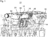
- the FIG. 1 shows a portion of an internal combustion engine 10.
- the internal combustion engine 10 has a device 12 for mounting a control device (electronic engine control unit) 14 on a component 16 of the internal combustion engine 10.
- the component 16 is a cylinder head.
- the component 16 may be, for example, a crankcase or a cylinder head cover.
- the device 12 for mounting the control device 14 has a first connection component 18, a second connection component 20 and a plurality of damping elements or decoupling elements 22 (cf. FIG. 2 ; hidden in FIG. 1 ) on.
- FIG. 2 can be removed, the damping elements 22 between the first connecting member 18 and the second connecting member 20 are arranged.
- the damping elements 22 damp vibrations between the connecting components 18, 20.
- the damping elements 22 are used for (at least partial) decoupling of the control unit 14 from the internal combustion engine 10 which is vibrating during operation.
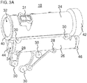
- the first connection member 18 includes a first tube piece 24, a second tube piece 26, a plurality of first and second attachment portions 28 and 30 (see FIG FIGS. 3A and 3B ) and a sensor receptacle 31.
- the first tube piece 24, the second tube piece 26 and the attachment portions 28, 30 are integrally provided with each other as a casting.
- the first tube piece 24 and the second tube piece 26 are connected to each other via a plurality of stiffening ribs 29.
- a first fluid channel 32 extends through the first tube piece 24 between a first inlet 40 and a first outlet 42.
- a second fluid channel 34 extends through the first second pipe section 26 between a second inlet 44 and a second outlet 46.
- the first fluid channel 32 and / or the second fluid channel 34 may have a plurality of inlets and / or outlets and also be designed to be more continuous.
- the inlets 40, 44 and the outlets 42, 46 can be used as flanges for connection to lines of the internal combustion engine 10 (for example, an intake air line 50, an exhaust gas recirculation line 52, cf. FIG. 1 ) be formed.
- the first outlet 42 of the first tube piece 24 is configured so that a throttle valve device 48 can be attached to the first outlet 42 (see FIG. FIG. 1 ).
- the flanges can be generally designed so that other components that are needed for the function of the internal combustion engine 10 can be directly grown. This results in considerable freedom in the assembly and disassembly of components in case of service.
- the first fluid channel 32 and the second fluid channel 34 extend substantially straight and parallel to each other.
- the first fluid channel 32 and the first tube piece 24 form a portion of the charge air line 50 (see FIG. 1 ) of an intake air system of the engine 10.
- the second fluid passage 34 and the second pipe 26 form a portion of the exhaust gas recirculation passage 52 (see FIG FIG. 1 ) of the internal combustion engine 10.
- the pipe sections 24, 26 are integrated, for example via suitable clamps and flanges in the lines 50, 52, that is connected as line sections with other line sections of the lines 50, 52.
- the first fluid channel 32 and the second fluid channel 34 may have different flow cross sections, which are adapted to the respective function.
- the flow cross section of the first fluid channel 32 used as an inlet air channel is greater than the flow cross section of the second fluid channel 34 used as an exhaust gas recirculation channel.
- the first attachment portions 28 are configured to attach the first connection member 18 to the cylinder head 16 (see FIG FIG. 1 ) to fix.
- the first attachment regions 28 may, for example, be provided as through-holes into which screws or the like can be inserted.
- the bolts fasten the first connection member 18 to the cylinder head 16.
- two first attachment portions 28 are provided. In other embodiments, more or less first attachment regions 28 may be provided.
- the second attachment regions 30 are configured to attach the damping elements 22 to the first connection component 18, such that the second connection component 20 is connected via the damping elements 22 (see FIG FIG. 2 ) attachable to the first connecting member 18 is.
- a screw or the like can be screwed by the second connecting component 20 through a through hole in the damping element 22 into an opening in the second fastening region 30.
- FIG. 3A the embodiment shown on five spaced apart second attachment portions 30.
- the second attachment regions 30 are positioned so that the vibration from the first connection component 18 to the second connection component 20 is damped as well as possible by providing the damping elements 22 at the second attachment regions 30.
- the second attachment regions 30 and the damping elements 22 are arranged in particular at positions with oscillation maxima during operation of the internal combustion engine 10.
- two second attachment regions 30 are positioned between the first tube piece 24 and the second tube piece 26 (see FIG FIG. 3A ).
- Another three mounting portions 30 are positioned below the second tubular piece 26 in the installed state.
- the first and second attachment regions 28 and 30 are arranged and configured such that the channel guides of the first fluid channel 32 and the second fluid channel 34 are not affected or impaired to the smallest possible extent (this applies in particular to the flow channel 32).
- a streamlined, smooth-walled (ebenwandige) wiring, in particular the first fluid channel 32 without constricting fferbutzen or the like can be made possible. That is, the first fluid channel 32 undergoes no change in the flow area by providing the first and second attachment portions 28 and 30.
- the sensor receptacle 31 is arranged on the first pipe section 24.
- the sensor receptacle 31 has a sensor channel 33, which opens into the first fluid channel 32 (see. FIG. 4 ).
- a sensor 38 (see. FIG. 1 ) are attached.
- the sensor 38 may be inserted through the sensor channel 33 so that it projects at least partially into the first fluid channel 32.
- the sensor 38 may be, for example, a pressure sensor, a temperature sensor or a flow rate sensor.
- An inner circumferential surface of the first fluid channel 32 may include a Venturi tube section 36 (defined narrowing of the flow cross section of the first fluid channel 32).
- the venturi tube section 36 allows for a liquid or gaseous medium flowing through the first fluid channel 32 to maximize the dynamic pressure (dynamic pressure) at the narrowest point of the first fluid channel 32 and minimize the static pressure. So, for example taking into account a measured media temperature and the known cross-sectional area in the narrowest cross-section of the Venturi tube section 36, the amount of media flowing through can be calculated.
- the narrowest cross-sectional area can be produced in particular by mechanical processing, so that their actual size corresponds as closely as possible to the desired size used for the calculation.
- the narrowest cross-sectional area can also be represented by a casting process with sufficient accuracy.
- the first fluid channel 32 can thus be adapted to a measuring principle or a measurement requirement of the sensor 38. In other embodiments, more or less sensors with corresponding sensor receptacles and possibly adapted geometries of the first or second fluid channel 32, 34 may be provided on the first and / or the second tube piece 24, 26.
- the second connection member 20 is connected (only) via the damping elements 22 to the first connection component 18 (damped).
- the controller 14 is mounted to the second connection member 20, for example screwed.
- the second connection member 20 is externally attached to the first connection member 18.
- the control unit 14 and the second connection component 20 are arranged outside the first fluid channel 32 and the second fluid channel 34.
- the second connection component 20 carries the control unit 14.
Landscapes
- Engineering & Computer Science (AREA)
- Chemical & Material Sciences (AREA)
- Combustion & Propulsion (AREA)
- Mechanical Engineering (AREA)
- General Engineering & Computer Science (AREA)
- Analytical Chemistry (AREA)
- Physics & Mathematics (AREA)
- Microelectronics & Electronic Packaging (AREA)
- Fluid Mechanics (AREA)
- Thermal Sciences (AREA)
- Cylinder Crankcases Of Internal Combustion Engines (AREA)
- Vibration Prevention Devices (AREA)
- Hybrid Electric Vehicles (AREA)
- Arrangement Or Mounting Of Propulsion Units For Vehicles (AREA)
Abstract
Description
- Die Erfindung betrifft eine Vorrichtung zur Anbringung eines Steuergeräts an einer Komponente eines Verbrennungsmotors. Die Erfindung betrifft ferner einen Verbrennungsmotor mit einer Vorrichtung zur Anbringung eines Steuergeräts an einer Komponente des Verbrennungsmotors. Zudem bezieht sich die Erfindung auf ein Kraftfahrzeug, insbesondere ein Nutzfahrzeug, mit einem Verbrennungsmotor oder einer Vorrichtung zur Anbringung eines Steuergeräts an einer Komponente eines Verbrennungsmotors.
- Motorsteuergeräte oder Steuereinheiten können außen an einer Komponente eines Verbrennungsmotors, zum Beispiel einem Kurbelgehäuse, angebaut werden. Aus schwingungstechnischen Gründen werden die Steuergeräte häufig unter Zwischenschaltung von Dämpfungselementen aus elastischen Werkstoffen an dem Verbrennungsmotor angebracht. Die Dämpfungselemente dämpfen die vom Verbrennungsmotor herrührenden Schwingungen, sodass das Steuergerät dem Einsatz am Verbrennungsmotor über die Lebensdauer des Verbrennungsmotors erträgt.
- Bei Konstruktionen, in denen das Steuergerät außen am Verbrennungsmotor angebracht wird, erfolgt die Anbringung häufig mittels zweier Konsolen oder Verbindungsbauteilen. Das erste Verbindungsbauteil ist fest mit dem Verbrennungsmotor verbunden. Das zweite Verbindungsbauteil ist fest mit dem Steuergerät verbunden. Zwischen den beiden Konsolen befinden sich die Dämpfungselemente.
- Im Stand der Technik sind ebenfalls Konstruktionen bekannt, bei denen ein Steuergerät direkt in ein Einlassluftsystem eines Verbrennungsmotors integriert ist, sodass das Steuergerät von der Einlassluft gekühlt werden kann. Derartige Systeme sind beispielsweise in der
DE 101 04 568 A1 , derUS 2002/104490 A1 und derDE 103 03 763 A offenbart. - Ausgehend von einer Konstruktion, bei der ein Steuergerät außen an einer Komponente des Verbrennungsmotors gedämpft über ein Verbindungsbauteil angebracht ist, ist es eine Aufgabe der Erfindung, das Verbindungsbauteil so zu erweitern, dass es zusätzliche Funktionen erfüllt.
- Diese Aufgabe wird durch eine Vorrichtung zur Anbringung eines Steuergeräts mit den Merkmalen des unabhängigen Anspruchs gelöst. Vorteilhafte Ausführungsformen und Anwendungen der Erfindung ergeben sich aus den abhängigen Ansprüchen.
- Die Vorrichtung zur Anbringung eines Steuergeräts, vorzugsweise eines elektronischen Motorsteuergeräts, an einer Komponente eines Verbrennungsmotors weist ein erstes oder motorseitiges Verbindungsbauteil und ein zweites oder steuergeräteseitiges Verbindungsbauteil auf. Das erste Verbindungsbauteil ist dazu ausgebildet ist, an der Komponente des Verbrennungsmotors angebracht oder befestigt zu werden. Das erste Verbindungsbauteil weist einen ersten Fluidkanal auf. Das zweite Verbindungsbauteil ist über mindestens ein Dämpfungselement an dem ersten Verbindungsbauteil angebracht. Das zweite Verbindungsbauteil ist beabstandet von dem ersten Fluidkanal angeordnet. Das zweite Verbindungsbauteil ist zur Montage des Steuergeräts ausgebildet.
- Das erfindungsgemäße Vorsehen eines ersten Fluidkanals in dem ersten Verbindungsbauteil ermöglicht, dass das erste Verbindungsbauteil mehrere Funktionen erfüllt. Das erste Verbindungsbauteil dient einerseits weiterhin zur Anbringung eines Steuergeräts an einer Komponente des Verbrennungsmotors, zum Beispiel einen Zylinderkopf, eine Zylinderkopfabdeckung oder ein Kurbelgehäuse. Das Steuergerät wird insbesondere über ein zweites Verbindungsbauteil und mindestens ein Dämpfungselement gedämpft an dem ersten Verbindungsbauteil angebracht. Das zweite Verbindungsbauteil ist außen an dem ersten Verbindungsbauteil über das oder die Dämpfungselemente angebracht. Neben der Anbringung des Steuergeräts weist das erste Verbindungsbauteil eine weitere Funktion auf. Das erste Verbindungsbauteil ist dazu verwendbar, ein für den Betrieb des Verbrennungsmotors notwendiges Fluid in dem ersten Fluidkanal zu führen. Hierbei kann es sich beispielsweise um Ladeluft, Abgas, Hydraulikflüssigkeit, Kühlmittel, Kraftstoff, Druckluft oder Schmiermittel handeln. Folglich kann das erste Verbindungsbauteil beispielsweise in ein Ladeluftsystem des Verbrennungsmotors integriert werden. Der erste Fluidkanal kann beispielsweise einen Abschnitt einer Einlassluftleitung oder einer Abgasrückführleitung des Ladeluftsystems bilden.
- Das erste Verbindungsbauteil und/oder das zweite Verbindungsbauteil können insbesondere als Konsolen vorgesehen sein. Das erste Verbindungsbauteil kann fest mit der Komponente des Verbrennungsmotors verbunden sein. Das zweite Verbindungsbauteil kann fest mit dem Steuergerät verbunden sein. Das zweite Verbindungsbauteil ist über das mindestens eine Dämpfungselement gedämpft mit dem ersten Verbindungsbauteil verbunden, sodass das Steuergerät gedämpft mit der Komponente des Verbrennungsmotors verbunden ist. Das Steuergerät und das zweite Verbindungsbauteil können außerhalb des ersten Fluidkanals angeordnet sein. Das Dämpfungselement oder Entkopplungselement kann ein elastischer Körper sein, zum Beispiel ein Gummielement, das beispielsweise ein Durchgangsloch zur Befestigung des Gummielements mittels einer Schraube, eines Bolzens usw. aufweist. Das Dämpfungselement dämpft die Schwingungen zwischen dem ersten Verbindungsbauteil und dem zweiten Verbindungsbauteil, sodass die Schwingungen von dem Verbrennungsmotor gedämpft auf das Steuergerät übertragen werden. Es können eine Mehrzahl von zueinander beabstandeten Dämpfungselementen verwendet werden, die beispielsweise an Positionen mit Schwingungsmaxima des ersten Verbindungsbauteils befestigt sind.
- Gemäß einer Ausführungsform weist das erste Verbindungsbauteil einen zweiten Fluidkanal auf. Der zweite Fluidkanal kann insbesondere getrennt vom ersten Fluidkanal vorgesehen sein und/oder im Wesentlichen parallel zu dem ersten Fluidkanal verlaufen. Somit kann das erste Verbindungsbauteil ein zweites Medium in dem zweiten Fluidkanal führen.
- Vorteilhafterweise ist mindestens ein Befestigungsbereich zwischen einem ersten Fluidkanal (dem ersten Rohrstück mit dem ersten Fluidkanal) und einem zweiten Fluidkanal (dem zweiten Rohrstückmit dem zweiten Fluidkanal) angeordnet. Der mindestens eine Befestigungsbereich ist zur Befestigung von einen des mindestens einen Dämpfungselements ausgebildet. Alternativ oder zusätzlich ist der mindestens eine Befestigungsbereich zur Montage des ersten Verbindungsbauteils an der Komponente des Verbrennungsmotors ausgebildet. Folglich kann die Positionierung der Befestigungsbereiche mit Blick auf einen einfachen Zugang zur Montage verbessert werden. Eine Positionierung zwischen den Fluidkanälen kann ferner die Dämpfung dadurch verbessern, dass Dämpfungselemente gegebenenfalls dichter an Positionen mit Schwingungsmaxima positioniert werden können. Zudem wird ermöglicht, dass die Kanalverläufe der Fluidkanäle nicht negativ beeinflusst werden.
- In einem Ausführungsbeispiel sind ein erstes Rohrstück mit dem ersten Fluidkanal und ein zweites Rohrstück mit dem zweiten Fluidkanal durch mindestens eine Versteifungsrippe miteinander verbunden. Dies ermöglicht eine Erhöhung der Steifigkeit des ersten Verbindungsbauteils.
- Ein besonders bevorzugtes Ausführungsbeispiel sieht hierbei vor, dass das erste Verbindungsbauteil mindestens einen Befestigungsbereich zur Befestigung des mindestens einen Dämpfungselements, ein erstes Rohrstück mit dem ersten Fluidkanal und/oder ein zweites Rohrstück mit dem zweiten Fluidkanalaufweist. Das erste Rohrstück, das zweite Rohrstück und/oder der mindestens eine Befestigungsbereich sind integral miteinander ausgebildet (aus einem Stück gefertigt oder hergestellt). Somit kann die Teilezahl gegenüber einer herkömmlichen Konstruktion, bei der ein Verbindungsbauteil und ein oder zwei Rohrstücke mit Fluidkanal separat voneinander vorgesehen sind, verringert werden. Dies ermöglicht eine montage- und gewichtsgünstige Konstruktion.
- Alternativ oder zusätzlich kann das erste Verbindungsbauteil ein Gussteil sein. Die zusätzlichen Funktionen (z. B. Medienführung in Fluidkanälen und Aufnahme von Sensoren) des ersten Verbindungsbauteils lassen sich somit mit geringem konstruktiven Mehraufwand an dem ersten Verbindungsbauteil verwirklichen. Das im Gießverfahren hergestellte erste Verbindungsbauteil kann beispielsweise mittels eines spanabhebenden Verfahrens zum Aufweisen der zusätzlichen Funktion(en) nachbearbeitet werden.
- Gemäß einer weiteren Ausführungsvariante weist das erste Verbindungsbauteil ferner mindestens eine Sensoraufnahme zur Aufnahme eines Sensors auf. Dies ermöglicht, dass das erste Verbindungsbauteil eine weitere zusätzliche Funktion übernimmt. Das erste Verbindungsbauteil dient zusätzlich als eine Halterung für einen Sensor. Die mindestens eine Sensoraufnahme kann insbesondere in den ersten Fluidkanal und/oder den zweiten Fluidkanal münden. Folglich können Messungen die ein durch den ersten oder zweiten Fluidkanal strömendes Fluid betreffen, von einem in der Sensoraufnahme positionieren Sensor durchgeführt werden.
- Vorteilhafterweise weist der erste Fluidkanal und/oder der zweite Fluidkanal einen Venturirohrabschnitt (Venturidüsenabschnitt) auf und die mindestens eine Sensoraufnahme mündet insbesondere in den Venturirohrabschnitt. Ein Venturirohr ist durch eine Verengung eines Strömungsquerschnitts eines Kanals gekennzeichnet. Somit kann die Innengeometrie des ersten Fluidkanals und/oder des zweiten Fluidkanals an das Messprinzip eines Sensors in der Sensoraufnahme angepasst sein. Mit anderen Worten gesagt, kann die einen Venturirohrabschnitt aufweisende Innengeometrie des ersten Fluidkanals die Messung gemäß dem Messprinzip des verwendeten Sensors erst ermöglichen.
- In einigen Ausführungsformen kann die Vorrichtung ferner mindestens einen Sensor aufweisen, der in der mindestens einen Sensoraufnahme aufgenommen ist. Der Sensor kann beispielsweise ein Drucksensor, ein Temperatursensor oder ein Durchflussmengensensor sein. Der Sensor kann so in der Sensoraufnahme vorgesehen sein, dass er funktional mit dem ersten Fluidkanal und/oder dem zweiten Fluidkanal verbunden ist. Zum Beispiel kann der Sensor in den Fluidkanal zur Messung eines Fluiddrucks, einer Fluiddurchflussmenge, und/oder einer Fluidtemperatur zumindest teilweise hineinragen.
- Vorzugsweise ist an die Vorrichtung ferner eine Durchflussmengenänderungseinrichtung angebaut. Die Durchflussmengenänderungseinrichtung kann beispielsweise eine Drosselklappe oder ein Ventil sein. Die Durchflussmengenänderungseinrichtung kann an einem Einlass des ersten Fluidkanals, an einem Einlass des zweiten Fluidkanals, in dem ersten Fluidkanal, in dem zweiten Fluidkanal, an einem Auslass des ersten Fluidkanals und/oder an einem Auslass des zweiten Fluidkanals vorgesehen sein. Somit wird eine weitere Funktion, nämlich die Möglichkeit, eine Durchflussmenge durch den ersten Fluidkanal und/oder den zweiten Fluidkanal zu verändern, in das erste Verbindungsbauteil integriert.
- Weitere Bauteile können an den Einlass, in den ersten Fluidkanal und/oder an den Auslass des ersten Fluidkanals und/oder des zweiten Fluidkanals eingebaut oder angebaut werden. Diese Bauteile umfassen beispielsweise Filter, Umlenkbleche, Rohrleitungen usw.
- In einem weiteren Ausführungsbeispiel weist der erste Fluidkanal und/oder der zweite Fluidkanal einen Einlass oder mehrere Einlässe zum Vereinigen von mehreren Teilströmungen und einen Auslass oder mehrere Auslässe zum Verzweigen in mehrere Teilströmungen auf. Dies ermöglicht eine flexible Anpassung an das Leitungssystem, in das der erste Fluidkanal und/oder der zweite Fluidkanal des ersten Verbindungsbauteils, zu integrieren ist.
- Alternativ oder zusätzlich kann der erste Fluidkanal und/oder der zweite Fluidkanal mehrgängig ausgeführt sein, d. h. mehrere (Teil-) Strömungsgänge aufweisen.
- Vorzugsweise weist das mindestens eine Dämpfungselement eine Mehrzahl von Dämpfungselementen auf, die an zueinander beabstandeten Positionen des ersten Verbindungsbauteils angeordnet sind. Die Mehrzahl von Dämpfungselementen sind im Einbauzustand des ersten Verbindungsbauteils, d. h. im an der Komponente des Verbrennungsmotors montierten Zustand, insbesondere in einer Vertikalrichtung und/oder in einer Horizontalrichtung voneinander beabstandet.
- Die Erfindung betrifft zudem einen Verbrennungsmotor für ein Kraftfahrzeug, insbesondere ein Nutzfahrzeug. Der Verbrennungsmotor weist die Vorrichtung zur Anbringung eines Steuergeräts wie hierin offenbart auf. Der erste Fluidkanal und/oder der zweite Fluidkanal des ersten Verbindungsbauteils bildet einen Abschnitt einer Einlassluftleitung des Verbrennungsmotors, einen Abschnitt einer Abgasleitung des Verbrennungsmotors, einen Abschnitt einer Abgasrückführleitung des Verbrennungsmotors, einen Abschnitt einer Druckluftleitung des Verbrennungsmotors, einen Abschnitt einer Hydraulikleitung des Verbrennungsmotors, einen Abschnitt einer Ölleitung des Verbrennungsmotors, einen Abschnitt einer Kraftstoffleitung des Verbrennungsmotors oder einen Abschnitt einer Kühlmittelleitung des Verbrennungsmotors.
- Die Komponente, an der das erste Verbindungsbauteil montiert wird, ist insbesondere ein Kurbelgehäuse, ein Zylinderkopf und/oder eine Zylinderkopfabdeckung.
- Die Erfindung betrifft weiterhin ein Kraftfahrzeug, insbesondere ein Nutzfahrzug, mit einer Vorrichtung zur Anbringung eines Steuergeräts an einer Komponente eines Verbrennungsmotors wie hierin offenbart oder einem Verbrennungsmotor wie hierin offenbart.
- Gemäß einem weiteren Gesichtspunkt der Erfindung kann ein (erstes oder motorseitiges) Verbindungsbauteil einer Vorrichtung zur Anbringung eines Steuergeräts an einer Komponente eines Verbrennungsmotors vorgesehen sein. Das Verbindungsbauteil ist dazu ausgebildet, an der Komponenten des Verbrennungsmotors angebracht zu werden. Das Verbindungsbauteil weist mindestens einen Fluidkanal, insbesondere einen ersten Fluidkanal und einen zweiten Fluidkanal, auf. Der erste Fluidkanal kann sich durch ein erstes Rohrstück und der zweite Fluidkanal kann sich durch ein zweites Rohrstück erstrecken. Das Verbindungsbauteil weist ferner einen Befestigungsbereich auf, der zur Befestigung von mindestens einem Dämpfungselement zur Anbringung eines weiteren Verbindungsbauteils zur Montage des Steuergeräts an dem Verbindungsbauteil ausgebildet ist. Das weitere Verbindungsbauteil, das mindestens eine Dämpfungselement und/oder der Befestigungsbereich sind beabstandet von dem ersten Fluidkanal und/oder dem zweiten Fluidkanal angeordnet. Das erste Rohrstück, das zweite Rohrstück und/oder der Befestigungsbereich können insbesondere integral miteinander, zum Beispiel als ein Gussteil, ausgebildet sein. Das Verbindungsbauteil kann wie das hierin offenbarte erste Verbindungsbauteil ausgebildet sein.
- Die zuvor beschriebenen bevorzugten Ausführungsformen und Merkmale der Erfindung sind beliebig miteinander kombinierbar. Weitere Einzelheiten und Vorteile der Erfindung werden im Folgenden unter Bezug auf die beigefügten Zeichnungen beschrieben. Es zeigen:
- Figur 1
- eine perspektivische Ansicht eines Verbrennungsmotors mit einer Vorrichtung zur Anbringung eines Steuergeräts;
- Figur 2
- eine Schnittansicht durch einen Bereich des Verbrennungsmotors und der Vorrichtung zur Anbringung des Steuergeräts;
- Figur 3A
- eine perspektivische Vorderansicht eines ersten Verbindungsbauteils der Vorrichtung zur Anbringung des Steuergeräts;
- Figur 3B
- eine perspektivische Rückansicht des ersten Verbindungsbauteils; und
- Figur 4
- eine Längsschnittansicht durch ein erstes Rohrstück des ersten Verbindungsbauteils.
- Die
Figur 1 zeigt einen Bereich eines Verbrennungsmotors 10. Der Verbrennungsmotor 10 weist eine Vorrichtung 12 zur Anbringung eines Steuergeräts (elektronischen Motorsteuergeräts) 14 an einer Komponente 16 des Verbrennungsmotors 10 auf. In dem gezeigten Ausführungsbeispiel ist die Komponente 16 ein Zylinderkopf. In anderen Ausführungsformen kann die Komponente 16 beispielsweise ein Kurbelgehäuse oder eine Zylinderkopfabdeckung sein. - Die Vorrichtung 12 zur Anbringung des Steuergeräts 14 weist ein erstes Verbindungsbauteil 18, ein zweites Verbindungsbauteil 20 und eine Mehrzahl von Dämpfungselementen oder Entkopplungselementen 22 (vgl.
Figur 2 ; verdeckt inFigur 1 ) auf. - Wie der
Figur 2 entnommen werden kann, sind die Dämpfungselemente 22 zwischen dem ersten Verbindungsbauteil 18 und dem zweiten Verbindungsbauteil 20 angeordnet. Die Dämpfungselemente 22 dämpfen Schwingungen zwischen den Verbindungsbauteilen 18, 20. Die Dämpfungselemente 22 dienen zum (zumindest teilweisen) Entkoppeln des Steuergeräts 14 von dem im Betrieb vibrierenden Verbrennungsmotor 10. - Nachfolgend ist das erste Verbindungsbauteil 18 unter Bezugnahme auf die
Figuren 2 bis 4 beschrieben. Das erste Verbindungsbauteil 18 weist ein erstes Rohrstück 24, ein zweites Rohrstück 26, eine Mehrzahl von ersten und zweiten Befestigungsbereichen 28 und 30 (sieheFiguren 3A und3B ) und eine Sensoraufnahme 31 auf. Das erste Rohrstück 24, das zweite Rohrstück 26 und die Befestigungsbereiche 28, 30 sind einstückig miteinander als ein Gussteil vorgesehen. Das erste Rohrstück 24 und das zweite Rohrstück 26 sind über eine Mehrzahl von Versteifungsrippen 29 miteinander verbunden. - Ein erster Fluidkanal 32 erstreckt sich durch das erste Rohrstück 24 zwischen einem ersten Einlass 40 und einem ersten Auslass 42. Ein zweiter Fluidkanal 34 erstreckt sich durch das zweite Rohrstück 26 zwischen einem zweiten Einlass 44 und einem zweiten Auslass 46. Der erste Fluidkanal 32 und/oder der zweite Fluidkanal 34 können mehrere Einlässe und/oder Auslässe aufweisen und auch mehrgängig ausgestaltet sein. Die Einlässe 40, 44 und die Auslässe 42, 46 können als Flansche zum Anschluss an Leitungen des Verbrennungsmotors 10 (zum Beispiel eine Einlassluftleitung 50, eine Abgasrückführleitung 52, vgl.
Figur 1 ) ausgebildet sein. Der erste Auslass 42 des ersten Rohrstücks 24 ist so ausgebildet, dass eine Drosselklappenvorrichtung 48 an dem ersten Auslass 42 angebracht werden kann (vgl.Figur 1 ). Die Flansche können allgemein so ausgeführt werden, dass weitere Bauteile, die für die Funktion des Verbrennungsmotors 10 benötigt werden, direkt angebaut werden können. So ergeben sich erhebliche Freiheiten bei der Montage und Demontage von Bauteilen im Servicefall. - Der erste Fluidkanal 32 und der zweite Fluidkanal 34 erstrecken sich im Wesentlichen geradlinig und parallel zueinander. Der erste Fluidkanal 32 und das erste Rohrstück 24 bilden einen Abschnitt der Ladeluftleitung 50 (siehe
Figur 1 ) eines Einlassluftsystems des Verbrennungsmotors 10. Der zweite Fluidkanal 34 und das zweite Rohrstück 26 bilden einen Abschnitt der Abgasrückführleitung 52 (sieheFigur 1 ) des Verbrennungsmotors 10. Die Rohrstücke 24, 26 sind beispielsweise über geeignete Schellen und Flansche in die Leitungen 50, 52 integriert, d. h. als Leitungsabschnitte mit anderen Leitungsabschnitten der Leitungen 50, 52 verbunden. Der erste Fluidkanal 32 und der zweite Fluidkanal 34 können unterschiedliche Strömungsquerschnitte aufweisen, die an die jeweilige Funktion angepasst sind. Der Strömungsquerschnitt des als Einlassluftkanal verwendeten ersten Fluidkanals 32 ist größer als der Strömungsquerschnitt des als Abgasrückführungskanals verwendeten zweiten Fluidkanals 34. - Die ersten Befestigungsbereiche 28 sind dazu ausgebildet, das erste Verbindungsbauteil 18 an dem Zylinderkopf 16 (siehe
Figur 1 ) zu befestigen. Die ersten Befestigungsbereiche 28 können beispielsweise als Durchgangslöcher vorgesehen sein, in die Schrauben oder dergleichen einführbar sind. Die Schrauben befestigen das erste Verbindungsbauteil 18 an dem Zylinderkopf 16. In der dargestellten Ausführungsform sind zwei erste Befestigungsbereiche 28 vorgesehen. In anderen Ausführungsformen können mehr oder weniger erste Befestigungsbereiche 28 vorgesehen sein. - Die zweiten Befestigungsbereiche 30 sind dazu ausgebildet, die Dämpfungselemente 22 an dem ersten Verbindungsbauteil 18 zu befestigen, sodass das zweite Verbindungsbauteil 20 über die Dämpfungselemente 22 (siehe
Figur 2 ) an dem ersten Verbindungsbauteil 18 anbringbar ist. Dazu kann beispielsweise eine Schraube oder dergleichen von dem zweiten Verbindungsbauteil 20 durch ein Durchgangsloch in dem Dämpfungselement 22 in eine Öffnung im zweiten Befestigungsbereich 30 eingeschraubt werden. Wie insbesondere derFigur 3A zu entnehmen ist, weist die gezeigte Ausführungsform fünf zueinander beabstandete zweite Befestigungsbereiche 30 auf. Die zweiten Befestigungsbereiche 30 sind so positioniert, dass die Schwingung von dem ersten Verbindungsbauteil 18 zu dem zweiten Verbindungsbauteil 20 durch Vorsehen der Dämpfungselemente 22 an den zweiten Befestigungsbereichen 30 möglichst gut gedämpft werden. Mit anderen Worten gesagt, sind die zweiten Befestigungsbereiche 30 und die Dämpfungselemente 22 insbesondere an Positionen mit Schwingungsmaxima im Betrieb des Verbrennungsmotors 10 angeordnet. Zum Beispiel sind zwei zweite Befestigungsbereiche 30 zwischen dem ersten Rohrstück 24 und dem zweiten Rohrstück 26 positioniert (sieheFigur 3A ). Weitere drei Befestigungsbereiche 30 sind im Einbauzustand unterhalb des zweiten Rohrstücks 26 positioniert. Damit sind die Befestigungsschrauben für Schraubwerkzeuge gut zugänglich angeordnet. - Die ersten und zweiten Befestigungsbereiche 28 und 30 sind so angeordnet und ausgebildet, dass die Kanalführungen des ersten Fluidkanal 32 und des zweiten Fluidkanals 34 nicht oder in möglichst geringen Umfang beeinträchtigt werden (besonders trifft dies für den Strömungskanal 32 zu). Somit kann eine strömungsgünstige, glattwandige (ebenwandige) Leitungsführung insbesondere des ersten Fluidkanals 32 ohne einengende Schraubbutzen oder dergleichen ermöglicht werden. D.h., der erste Fluidkanal 32 erfährt keine Veränderung des Strömungsquerschnitts durch Vorsehen der ersten und zweiten Befestigungsbereiche 28 und 30.
- Die Sensoraufnahme 31 ist an dem ersten Rohrstück 24 angeordnet. Die Sensoraufnahme 31 weist einen Sensorkanal 33 auf, der in den ersten Fluidkanal 32 mündet (vgl.
Figur 4 ). An der Sensoraufnahme 31 kann ein Sensor 38 (vgl.Figur 1 ) befestigt werden. Der Sensor 38 kann durch den Sensorkanal 33 eingeführt werden, sodass er zumindest teilweise in den ersten Fluidkanal 32 hineinragt. Der Sensor 38 kann beispielsweise ein Drucksensor, ein Temperatursensor oder ein Durchflussmengensensor sein. Eine Innenumfangsfläche des ersten Fluidkanals 32 kann einen Venturirohrabschnitt 36 (definierte Verengung des Strömungsquerschnitts des ersten Fluidkanals 32) aufweisen. In der gezeigten Ausführungsform ermöglicht der Venturirohrabschnitt 36, dass für ein durch den ersten Fluidkanal 32 strömendes flüssiges oder gasförmiges Medium der dynamische Druck (Staudruck) an der engsten Stelle des ersten Fluidkanals 32 maximal und der statische Druck minimal wird. So kann beispielsweise unter Berücksichtigung einer gemessenen Medientemperatur und der bekannten Querschnittsfläche im engsten Querschnitt des Venturirohrabschnitts 36 die durchströmende Medienmenge berechnet werden. Die engste Querschnittsfläche kann insbesondere durch mechanische Bearbeitung hergestellt werden, sodass deren Istgröße möglichst genau der für die Berechnung herangezogenen Sollgröße entspricht. Die engste Querschnittsfläche kann aber auch durch einen Gießprozess mit hinreichender Genauigkeit dargestellt werden. Allgemein kann der erste Fluidkanal 32 somit an ein Messprinzip oder eine Messanforderung des Sensors 38 angepasst sein. In anderen Ausführungsformen können mehr oder weniger Sensoren mit entsprechenden Sensoraufnahmen und gegebenenfalls angepassten Geometrien des ersten oder zweiten Fluidkanals 32, 34 an dem ersten und/oder dem zweiten Rohrstück 24, 26 vorgesehen sein. - Nachfolgend ist das zweite Verbindungsbauteil 20 unter Bezugnahme auf die
Figuren 1 und2 beschrieben. Das zweite Verbindungsbauteil 20 ist (einzig) über die Dämpfungselemente 22 mit dem ersten Verbindungsbauteil 18 (gedämpft) verbunden. Das Steuergerät 14 ist an das zweite Verbindungsbauteil 20 montiert, zum Beispiel angeschraubt. Das zweite Verbindungsbauteil 20 ist außen an dem ersten Verbindungsbauteil 18 angebracht. Das Steuergerät 14 und das zweite Verbindungsbauteil 20 sind außerhalb des ersten Fluidkanals 32 und des zweiten Fluidkanals 34 angeordnet. Das zweite Verbindungsbauteil 20 trägt das Steuergerät 14. - Die Erfindung ist nicht auf die vorstehend beschriebenen bevorzugten Ausführungsbeispiele beschränkt. Vielmehr ist eine Vielzahl von Varianten und Abwandlungen möglich, die ebenfalls von dem Erfindungsgedanken Gebrauch machen und deshalb in den Schutzbereich fallen. Insbesondere beansprucht die Erfindung auch Schutz für den Gegenstand und die Merkmale der Unteransprüche unabhängig von den in Bezug genommenen Ansprüchen.
-
- 10
- Verbrennungsmotor
- 12
- Verbindungsvorrichtung
- 14
- Steuergerät
- 16
- Kurbelgehäuse
- 18
- erstes Verbindungsbauteil
- 20
- zweites Verbindungsbauteil
- 22
- Dämpfungselement
- 24
- erstes Rohrstück
- 26
- zweites Rohrstück
- 28
- erster Befestigungsbereich
- 29
- Versteifungsrippe
- 30
- zweiter Befestigungsbereich
- 31
- Sensoraufnahme
- 32
- erster Fluidkanal
- 33
- Sensorkanal
- 34
- zweiter Fluidkanal
- 36
- Venturirohrabschnitt
- 38
- Sensor
- 40
- erster Einlass
- 42
- erster Auslass
- 44
- zweiter Einlass
- 46
- zweiter Auslass
- 48
- Drosselklappenvorrichtung
- 50
- Einlassluftleitung
- 52
- Abgasrückführleitung
Claims (13)
- Vorrichtung (12) zur Anbringung eines Steuergeräts (14), vorzugsweise eines elektronischen Motorsteuergeräts, an einer Komponente (16) eines Verbrennungsmotors (10), aufweisend:ein erstes Verbindungsbauteil (18), das dazu ausgebildet ist, an der Komponente (16) des Verbrennungsmotors (10) angebracht zu werden, wobei das erste Verbindungsbauteil (18) einen ersten Fluidkanal (32) aufweist, undein zweites Verbindungsbauteil (20), das über mindestens ein Dämpfungselement (22) an dem ersten Verbindungsbauteil (18) beabstandet zu dem ersten Fluidkanal (32) angebracht und zur Montage des Steuergeräts (14) ausgebildet ist.
- Vorrichtung (12) nach Anspruch 1, wobei das erste Verbindungsbauteil (18) einen zweiten Fluidkanal (34) aufweist, der insbesondere getrennt vom ersten Fluidkanal (32) vorgesehen ist und/oder im Wesentlichen parallel zu dem ersten Fluidkanal (32) verläuft.
- Vorrichtung (12) nach Anspruch 2, wobei mindestens ein Befestigungsbereich (28, 30) zwischen dem ersten Fluidkanal (32) und dem zweiten Fluidkanal (34) angeordnet und zur Befestigung von einen des mindestens einen Dämpfungselements (22) und/oder des ersten Verbindungsbauteils (18) an der Komponente (16) des Verbrennungsmotors (10) ausgebildet ist.
- Vorrichtung (12) nach Anspruch 2 oder Anspruch 3, wobei ein erstes Rohrstück (24) mit dem ersten Fluidkanal (32) und ein zweites Rohrstück (26) mit dem zweiten Fluidkanal (34) durch mindestens eine Versteifungsrippe (29) miteinander verbunden sind.
- Vorrichtung (12) nach einem der vorherigen Ansprüche, wobei:das erste Verbindungsbauteil (18) mindestens einen Befestigungsbereich (30) zur Befestigung des mindestens einen Dämpfungselements (22), ein erstes Rohrstück (24) mit dem ersten Fluidkanal (32) und/oder ein zweites Rohrstück (26) mit dem zweiten Fluidkanal (34) aufweist, wobei das erste Rohrstück (24), das zweite Rohrstück (26) und/oder der mindestens eine Befestigungsbereich (30) integral miteinander ausgebildet sind, und/oderdas erste Verbindungsbauteil (18) ein Gussteil ist.
- Vorrichtung (12) nach einem der vorherigen Ansprüche, wobei das erste Verbindungsbauteil (18) ferner mindestens eine Sensoraufnahme (31) zur Aufnahme eines Sensors (38) aufweist, die insbesondere in den ersten Fluidkanal (32) und/oder in den zweiten Fluidkanal (34) mündet.
- Vorrichtung (12) nach Anspruch 6, wobei:der erste Fluidkanal (32) und/oder der zweite Fluidkanal (34) einen Venturirohrabschnitt (36) aufweist und die mindestens eine Sensoraufnahme (31) insbesondere in den Venturirohrabschnitt (36) mündet, und/oderdie Vorrichtung (12) ferner mindestens einen Sensor (38), insbesondere einen Drucksensor, einen Temperatursensor und/oder einen Durchflussmengensensor, aufweist, wobei der mindestens eine Sensor (38) vorzugsweise in der mindestens einen Sensoraufnahme (31) angeordnet ist.
- Vorrichtung (12) nach einem der vorherigen Ansprüche, ferner aufweisend mindestens eine Durchflussmengenänderungseinrichtung (48), insbesondere eine Drosselklappe oder ein Ventil, die an einem Einlass (40) des ersten Fluidkanals (32), an einem Einlass (44) des zweiten Fluidkanals (34), in dem ersten Fluidkanal (32), in dem zweiten Fluidkanal (34), an einem Auslass (42) des ersten Fluidkanals (32) und/oder an einem Auslass (46) des zweiten Fluidkanals (34) vorgesehen ist.
- Vorrichtung (12) nach einem der vorherigen Ansprüche, wobei:der erste Fluidkanal (32) und/oder der zweite Fluidkanal (34) einen oder mehrere Einlässe (40, 44) zum Vereinigen von mehreren Teilströmungen und einen oder mehrere Auslässe (42, 56) zum Verzweigen in mehrere Teilströmungen aufweist, und/oder der erste Fluidkanal (32) und/oder der zweite Fluidkanal (34) mehrgängig ausgeführt ist.
- Vorrichtung (12) nach einem der vorherigen Ansprüche, wobei das mindestens eine Dämpfungselement (22) eine Mehrzahl von Dämpfungselementen (22) aufweist, die an zueinander beabstandeten Positionen des ersten Verbindungsbauteils (18) angeordnet sind, wobei die Mehrzahl von Dämpfungselementen (22) im Einbauzustand des ersten Verbindungsbauteils (18) insbesondere in einer Vertikalrichtung und/oder in einer Horizontalrichtung voneinander beabstandet sind.
- Verbrennungsmotor (10) für ein Kraftfahrzeug, insbesondere ein Nutzfahrzeug, aufweisend die Vorrichtung (12) nach einem der vorherigen Ansprüche, wobei der erste Fluidkanal (32) und/oder der zweite Fluidkanal (34) einen Abschnitt einer Einlassluftleitung (50) des Verbrennungsmotors (10), einen Abschnitt einer Abgasleitung des Verbrennungsmotors (10), einen Abschnitt einer Abgasrückführleitung (52) des Verbrennungsmotors (10), einen Abschnitt einer Druckluftleitung des Verbrennungsmotors (10), einen Abschnitt einer Hydraulikleitung des Verbrennungsmotors (10), einen Abschnitt einer Ölleitung des Verbrennungsmotors (10), einen Abschnitt einer Kraftstoffleitung des Verbrennungsmotors (10) oder einen Abschnitt einer Kühlmittelleitung des Verbrennungsmotors (10) bildet.
- Verbrennungsmotor (10) nach Anspruch 11, aufweisend die Komponente (16), die als ein Kurbelgehäuse, ein Zylinderkopf und/oder eine Zylinderkopfabdeckung ausgebildet ist.
- Kraftfahrzeug, insbesondere Nutzfahrzeug, mit einer Vorrichtung (12) nach einem der Ansprüche 1 bis 10 oder einem Verbrennungsmotor (10) nach einem der Ansprüche 11 oder 12.
Applications Claiming Priority (1)
| Application Number | Priority Date | Filing Date | Title |
|---|---|---|---|
| DE102017000699.7A DE102017000699A1 (de) | 2017-01-26 | 2017-01-26 | Vorrichtung zur Anbringung eines Steuergeräts an einen Verbrennungsmotor |
Publications (2)
| Publication Number | Publication Date |
|---|---|
| EP3354891A1 true EP3354891A1 (de) | 2018-08-01 |
| EP3354891B1 EP3354891B1 (de) | 2021-03-10 |
Family
ID=60990712
Family Applications (1)
| Application Number | Title | Priority Date | Filing Date |
|---|---|---|---|
| EP18151687.3A Active EP3354891B1 (de) | 2017-01-26 | 2018-01-15 | Kraftfahrzeug mit verbrennungsmotor und vorrichtung zur anbringung eines steuergeräts an dem verbrennungsmotor |
Country Status (8)
| Country | Link |
|---|---|
| US (1) | US10648432B2 (de) |
| EP (1) | EP3354891B1 (de) |
| CN (1) | CN108468595B (de) |
| BR (1) | BR102018001557B1 (de) |
| CA (1) | CA2991558A1 (de) |
| DE (1) | DE102017000699A1 (de) |
| MX (1) | MX379972B (de) |
| RU (1) | RU2752369C2 (de) |
Families Citing this family (3)
| Publication number | Priority date | Publication date | Assignee | Title |
|---|---|---|---|---|
| JP6504201B2 (ja) * | 2017-05-29 | 2019-04-24 | マツダ株式会社 | 過給機付きエンジンの吸気温度センサ取付構造 |
| JP2019132233A (ja) * | 2018-02-01 | 2019-08-08 | トヨタ自動車株式会社 | 内燃機関のブローバイガス処理装置 |
| JP6763921B2 (ja) * | 2018-09-07 | 2020-09-30 | 本田技研工業株式会社 | エンジン |
Citations (9)
| Publication number | Priority date | Publication date | Assignee | Title |
|---|---|---|---|---|
| EP1057674A1 (de) * | 1999-06-02 | 2000-12-06 | Isuzu Motors Limited | Vorrichtung zur Befestigung einer elektronischen Steuereinheit im Motorraum |
| DE10104568A1 (de) | 2000-02-02 | 2001-08-09 | Denso Corp | Montageaufbau einer gedruckten Schalttafel für eine elektronische Steuereinheit |
| US20020104490A1 (en) | 2001-02-07 | 2002-08-08 | Keisuke Itakura | Cooling mechanism for engine electronic control module |
| DE10303763A1 (de) | 2002-01-31 | 2003-10-16 | Denso Corp | Ansaugmodul mit integral aufgenommener elektronischen Steuereinheit (ECU) |
| EP1422405A2 (de) * | 2002-11-25 | 2004-05-26 | Hitachi, Ltd. | Drosselklappengehäuse und Lufteinlasssystem für eine Brennkraftmaschine |
| WO2005031133A1 (de) * | 2003-10-02 | 2005-04-07 | Siemens Aktiengesellschaft | Luftansaugmodul für eine brennkraftmaschine mit impulsaufladung |
| US20160032877A1 (en) * | 2014-08-01 | 2016-02-04 | Yamaha Hatsudoki Kabushiki Kaisha | Vehicle, jet propelled watercraft, and engine unit |
| CN205297690U (zh) * | 2015-12-01 | 2016-06-08 | 潍柴动力股份有限公司 | 一种发动机ch喷射系统控制单元减震隔热装置 |
| DE102016212738A1 (de) * | 2015-07-16 | 2017-01-19 | Toyota Jidosha Kabushiki Kaisha | Fahrzeug |
Family Cites Families (7)
| Publication number | Priority date | Publication date | Assignee | Title |
|---|---|---|---|---|
| GB2339081A (en) | 1998-06-30 | 2000-01-12 | Cummins Engine Co Ltd | Cooling an engine control unit using fuel as coolant |
| DE10317705A1 (de) | 2003-04-17 | 2004-10-28 | Robert Bosch Gmbh | Gehäuse mit Kühlung für elektronische Steuergeräte, insbesondere in Kfz |
| RU54473U1 (ru) * | 2006-01-10 | 2006-06-27 | Открытое акционерное общество "РИФ" | Силовой полупроводниковый выпрямительно-инверторный преобразователь для транспортного средства |
| JP2007285229A (ja) * | 2006-04-18 | 2007-11-01 | Yamaha Marine Co Ltd | 船外機 |
| US7921830B2 (en) * | 2008-12-23 | 2011-04-12 | Deere & Company | Temperature controlled venturi for use with an EGR system in an internal combustion engine |
| DE102010063155A1 (de) | 2010-12-15 | 2012-06-21 | Robert Bosch Gmbh | Befestigungsvorrichtung für ein Gehäuse eines Steuergerätes |
| US9324195B2 (en) * | 2013-02-26 | 2016-04-26 | Polaris Industries Inc. | Recreational vehicle interactive, telemetry, mapping, and trip planning system |
-
2017
- 2017-01-26 DE DE102017000699.7A patent/DE102017000699A1/de not_active Withdrawn
-
2018
- 2018-01-11 CA CA2991558A patent/CA2991558A1/en not_active Abandoned
- 2018-01-15 EP EP18151687.3A patent/EP3354891B1/de active Active
- 2018-01-24 BR BR102018001557-5A patent/BR102018001557B1/pt active IP Right Grant
- 2018-01-25 MX MX2018001096A patent/MX379972B/es unknown
- 2018-01-25 RU RU2018102881A patent/RU2752369C2/ru active
- 2018-01-26 US US15/881,385 patent/US10648432B2/en active Active
- 2018-01-26 CN CN201810078481.6A patent/CN108468595B/zh active Active
Patent Citations (9)
| Publication number | Priority date | Publication date | Assignee | Title |
|---|---|---|---|---|
| EP1057674A1 (de) * | 1999-06-02 | 2000-12-06 | Isuzu Motors Limited | Vorrichtung zur Befestigung einer elektronischen Steuereinheit im Motorraum |
| DE10104568A1 (de) | 2000-02-02 | 2001-08-09 | Denso Corp | Montageaufbau einer gedruckten Schalttafel für eine elektronische Steuereinheit |
| US20020104490A1 (en) | 2001-02-07 | 2002-08-08 | Keisuke Itakura | Cooling mechanism for engine electronic control module |
| DE10303763A1 (de) | 2002-01-31 | 2003-10-16 | Denso Corp | Ansaugmodul mit integral aufgenommener elektronischen Steuereinheit (ECU) |
| EP1422405A2 (de) * | 2002-11-25 | 2004-05-26 | Hitachi, Ltd. | Drosselklappengehäuse und Lufteinlasssystem für eine Brennkraftmaschine |
| WO2005031133A1 (de) * | 2003-10-02 | 2005-04-07 | Siemens Aktiengesellschaft | Luftansaugmodul für eine brennkraftmaschine mit impulsaufladung |
| US20160032877A1 (en) * | 2014-08-01 | 2016-02-04 | Yamaha Hatsudoki Kabushiki Kaisha | Vehicle, jet propelled watercraft, and engine unit |
| DE102016212738A1 (de) * | 2015-07-16 | 2017-01-19 | Toyota Jidosha Kabushiki Kaisha | Fahrzeug |
| CN205297690U (zh) * | 2015-12-01 | 2016-06-08 | 潍柴动力股份有限公司 | 一种发动机ch喷射系统控制单元减震隔热装置 |
Also Published As
| Publication number | Publication date |
|---|---|
| RU2018102881A (ru) | 2019-07-25 |
| MX2018001096A (es) | 2018-11-09 |
| MX379972B (es) | 2025-03-11 |
| US10648432B2 (en) | 2020-05-12 |
| US20180209385A1 (en) | 2018-07-26 |
| RU2752369C2 (ru) | 2021-07-26 |
| RU2018102881A3 (de) | 2021-05-27 |
| CA2991558A1 (en) | 2018-07-26 |
| BR102018001557B1 (pt) | 2023-03-28 |
| CN108468595A (zh) | 2018-08-31 |
| BR102018001557A2 (pt) | 2018-10-30 |
| CN108468595B (zh) | 2022-07-01 |
| EP3354891B1 (de) | 2021-03-10 |
| DE102017000699A1 (de) | 2018-07-26 |
Similar Documents
| Publication | Publication Date | Title |
|---|---|---|
| DE102013217756A1 (de) | Schalldämpfer für ein Kraftfahrzeug | |
| EP3354891B1 (de) | Kraftfahrzeug mit verbrennungsmotor und vorrichtung zur anbringung eines steuergeräts an dem verbrennungsmotor | |
| DE112011103592T5 (de) | Abgasrückführungs-Kühleranordnung | |
| DE102008047504A1 (de) | Vorrichtung zur Messung einer Abgasrückführströmung einer Brennkraftmaschine | |
| DE3404887C2 (de) | Luftführungsgehäuse für eine Kühleinheit einer Brennkraftmaschine | |
| DE4410049A1 (de) | Luftmassenstrom-Sensor-Baugruppe und Sensorhalterung zur Befestigung desselben | |
| DE102015011175A1 (de) | Abgasanlage für eine Brennkraftmaschine | |
| WO2000022293A2 (de) | Luftführungssystem, insbesondere saugsystem einer verbrennungskraftmaschine | |
| DE102018000543A1 (de) | Filtereinrichtung mit einem Filterelement in einem Filtergehäuse | |
| EP1210565B1 (de) | Verwendung eines strömungsgleichrichters als kondensationsfalle für eine flüssigkeit in einer gasströmung | |
| DE102010015541A1 (de) | Luftreiniger mit in den Luftauslass eingebautem Resonator | |
| DE102005037521B4 (de) | Motorträger für eine in einem Fahrzeug betriebene Brennkraftmaschine | |
| EP3516234B1 (de) | Schraubenkompressor für ein nutzfahrzeug | |
| EP0580957B1 (de) | Luftfilter | |
| DE10252474B4 (de) | Brennkraftmaschine mit Abgasturbolader | |
| EP1022445B1 (de) | Gasleitungssystem, insbesondere Abgasleitungssystem für eine Fahrzeug-Brennkraftmaschine | |
| DE102006037761A1 (de) | Befestigungsanordnung für einen Ladeluftkühler und einen Wasserkühler | |
| DE102014009870A1 (de) | Motor-Abgasvorrichtung (EXHAUST DEVICE OF ENGINE) | |
| DE10222507A1 (de) | Vorrichtung zur Geräuschgestaltung bei einem Kraftfahrzeug | |
| DE102016111301B4 (de) | Kraftfahrzeug mit Vorrichtungen zur Aufhängung eines Abgasstrang an einer Karosserie des Kraftfahrzeug | |
| EP3769052B1 (de) | Sensoranordnung | |
| EP1013905B1 (de) | Katalysator-Anordnung an einem Kraftfahrzeug | |
| AT413437B (de) | Einrichtung zur schwingungsentkopplung und/oder zur längenkompensation und/oder zur kompensation eines seitlichen versatzes in fluiddurchströmten leitungen | |
| DE10339111A1 (de) | EGR-Leitung mit Doppeldichtungseinheit | |
| DE102005046215B4 (de) | Vorrichtung zur Ermittlung von Massenströmen an einem Kühler |
Legal Events
| Date | Code | Title | Description |
|---|---|---|---|
| PUAI | Public reference made under article 153(3) epc to a published international application that has entered the european phase |
Free format text: ORIGINAL CODE: 0009012 |
|
| STAA | Information on the status of an ep patent application or granted ep patent |
Free format text: STATUS: THE APPLICATION HAS BEEN PUBLISHED |
|
| AK | Designated contracting states |
Kind code of ref document: A1 Designated state(s): AL AT BE BG CH CY CZ DE DK EE ES FI FR GB GR HR HU IE IS IT LI LT LU LV MC MK MT NL NO PL PT RO RS SE SI SK SM TR |
|
| AX | Request for extension of the european patent |
Extension state: BA ME |
|
| STAA | Information on the status of an ep patent application or granted ep patent |
Free format text: STATUS: REQUEST FOR EXAMINATION WAS MADE |
|
| 17P | Request for examination filed |
Effective date: 20190123 |
|
| RBV | Designated contracting states (corrected) |
Designated state(s): AL AT BE BG CH CY CZ DE DK EE ES FI FR GB GR HR HU IE IS IT LI LT LU LV MC MK MT NL NO PL PT RO RS SE SI SK SM TR |
|
| STAA | Information on the status of an ep patent application or granted ep patent |
Free format text: STATUS: EXAMINATION IS IN PROGRESS |
|
| 17Q | First examination report despatched |
Effective date: 20190507 |
|
| RAP1 | Party data changed (applicant data changed or rights of an application transferred) |
Owner name: MAN TRUCK & BUS SE |
|
| GRAP | Despatch of communication of intention to grant a patent |
Free format text: ORIGINAL CODE: EPIDOSNIGR1 |
|
| STAA | Information on the status of an ep patent application or granted ep patent |
Free format text: STATUS: GRANT OF PATENT IS INTENDED |
|
| INTG | Intention to grant announced |
Effective date: 20201015 |
|
| GRAS | Grant fee paid |
Free format text: ORIGINAL CODE: EPIDOSNIGR3 |
|
| GRAA | (expected) grant |
Free format text: ORIGINAL CODE: 0009210 |
|
| STAA | Information on the status of an ep patent application or granted ep patent |
Free format text: STATUS: THE PATENT HAS BEEN GRANTED |
|
| AK | Designated contracting states |
Kind code of ref document: B1 Designated state(s): AL AT BE BG CH CY CZ DE DK EE ES FI FR GB GR HR HU IE IS IT LI LT LU LV MC MK MT NL NO PL PT RO RS SE SI SK SM TR |
|
| REG | Reference to a national code |
Ref country code: GB Ref legal event code: FG4D Free format text: NOT ENGLISH |
|
| REG | Reference to a national code |
Ref country code: CH Ref legal event code: EP Ref country code: AT Ref legal event code: REF Ref document number: 1370060 Country of ref document: AT Kind code of ref document: T Effective date: 20210315 |
|
| REG | Reference to a national code |
Ref country code: DE Ref legal event code: R096 Ref document number: 502018004186 Country of ref document: DE |
|
| REG | Reference to a national code |
Ref country code: IE Ref legal event code: FG4D Free format text: LANGUAGE OF EP DOCUMENT: GERMAN |
|
| REG | Reference to a national code |
Ref country code: NL Ref legal event code: FP |
|
| REG | Reference to a national code |
Ref country code: SE Ref legal event code: TRGR |
|
| REG | Reference to a national code |
Ref country code: LT Ref legal event code: MG9D |
|
| PG25 | Lapsed in a contracting state [announced via postgrant information from national office to epo] |
Ref country code: LT Free format text: LAPSE BECAUSE OF FAILURE TO SUBMIT A TRANSLATION OF THE DESCRIPTION OR TO PAY THE FEE WITHIN THE PRESCRIBED TIME-LIMIT Effective date: 20210310 Ref country code: BG Free format text: LAPSE BECAUSE OF FAILURE TO SUBMIT A TRANSLATION OF THE DESCRIPTION OR TO PAY THE FEE WITHIN THE PRESCRIBED TIME-LIMIT Effective date: 20210610 Ref country code: FI Free format text: LAPSE BECAUSE OF FAILURE TO SUBMIT A TRANSLATION OF THE DESCRIPTION OR TO PAY THE FEE WITHIN THE PRESCRIBED TIME-LIMIT Effective date: 20210310 Ref country code: HR Free format text: LAPSE BECAUSE OF FAILURE TO SUBMIT A TRANSLATION OF THE DESCRIPTION OR TO PAY THE FEE WITHIN THE PRESCRIBED TIME-LIMIT Effective date: 20210310 Ref country code: GR Free format text: LAPSE BECAUSE OF FAILURE TO SUBMIT A TRANSLATION OF THE DESCRIPTION OR TO PAY THE FEE WITHIN THE PRESCRIBED TIME-LIMIT Effective date: 20210611 Ref country code: NO Free format text: LAPSE BECAUSE OF FAILURE TO SUBMIT A TRANSLATION OF THE DESCRIPTION OR TO PAY THE FEE WITHIN THE PRESCRIBED TIME-LIMIT Effective date: 20210610 |
|
| PG25 | Lapsed in a contracting state [announced via postgrant information from national office to epo] |
Ref country code: RS Free format text: LAPSE BECAUSE OF FAILURE TO SUBMIT A TRANSLATION OF THE DESCRIPTION OR TO PAY THE FEE WITHIN THE PRESCRIBED TIME-LIMIT Effective date: 20210310 Ref country code: LV Free format text: LAPSE BECAUSE OF FAILURE TO SUBMIT A TRANSLATION OF THE DESCRIPTION OR TO PAY THE FEE WITHIN THE PRESCRIBED TIME-LIMIT Effective date: 20210310 |
|
| PG25 | Lapsed in a contracting state [announced via postgrant information from national office to epo] |
Ref country code: CZ Free format text: LAPSE BECAUSE OF FAILURE TO SUBMIT A TRANSLATION OF THE DESCRIPTION OR TO PAY THE FEE WITHIN THE PRESCRIBED TIME-LIMIT Effective date: 20210310 Ref country code: EE Free format text: LAPSE BECAUSE OF FAILURE TO SUBMIT A TRANSLATION OF THE DESCRIPTION OR TO PAY THE FEE WITHIN THE PRESCRIBED TIME-LIMIT Effective date: 20210310 Ref country code: SM Free format text: LAPSE BECAUSE OF FAILURE TO SUBMIT A TRANSLATION OF THE DESCRIPTION OR TO PAY THE FEE WITHIN THE PRESCRIBED TIME-LIMIT Effective date: 20210310 |
|
| PG25 | Lapsed in a contracting state [announced via postgrant information from national office to epo] |
Ref country code: PT Free format text: LAPSE BECAUSE OF FAILURE TO SUBMIT A TRANSLATION OF THE DESCRIPTION OR TO PAY THE FEE WITHIN THE PRESCRIBED TIME-LIMIT Effective date: 20210712 Ref country code: PL Free format text: LAPSE BECAUSE OF FAILURE TO SUBMIT A TRANSLATION OF THE DESCRIPTION OR TO PAY THE FEE WITHIN THE PRESCRIBED TIME-LIMIT Effective date: 20210310 Ref country code: RO Free format text: LAPSE BECAUSE OF FAILURE TO SUBMIT A TRANSLATION OF THE DESCRIPTION OR TO PAY THE FEE WITHIN THE PRESCRIBED TIME-LIMIT Effective date: 20210310 Ref country code: SK Free format text: LAPSE BECAUSE OF FAILURE TO SUBMIT A TRANSLATION OF THE DESCRIPTION OR TO PAY THE FEE WITHIN THE PRESCRIBED TIME-LIMIT Effective date: 20210310 Ref country code: IS Free format text: LAPSE BECAUSE OF FAILURE TO SUBMIT A TRANSLATION OF THE DESCRIPTION OR TO PAY THE FEE WITHIN THE PRESCRIBED TIME-LIMIT Effective date: 20210710 |
|
| REG | Reference to a national code |
Ref country code: DE Ref legal event code: R097 Ref document number: 502018004186 Country of ref document: DE |
|
| PLBE | No opposition filed within time limit |
Free format text: ORIGINAL CODE: 0009261 |
|
| STAA | Information on the status of an ep patent application or granted ep patent |
Free format text: STATUS: NO OPPOSITION FILED WITHIN TIME LIMIT |
|
| PG25 | Lapsed in a contracting state [announced via postgrant information from national office to epo] |
Ref country code: ES Free format text: LAPSE BECAUSE OF FAILURE TO SUBMIT A TRANSLATION OF THE DESCRIPTION OR TO PAY THE FEE WITHIN THE PRESCRIBED TIME-LIMIT Effective date: 20210310 Ref country code: AL Free format text: LAPSE BECAUSE OF FAILURE TO SUBMIT A TRANSLATION OF THE DESCRIPTION OR TO PAY THE FEE WITHIN THE PRESCRIBED TIME-LIMIT Effective date: 20210310 Ref country code: DK Free format text: LAPSE BECAUSE OF FAILURE TO SUBMIT A TRANSLATION OF THE DESCRIPTION OR TO PAY THE FEE WITHIN THE PRESCRIBED TIME-LIMIT Effective date: 20210310 |
|
| 26N | No opposition filed |
Effective date: 20211213 |
|
| PG25 | Lapsed in a contracting state [announced via postgrant information from national office to epo] |
Ref country code: SI Free format text: LAPSE BECAUSE OF FAILURE TO SUBMIT A TRANSLATION OF THE DESCRIPTION OR TO PAY THE FEE WITHIN THE PRESCRIBED TIME-LIMIT Effective date: 20210310 |
|
| PG25 | Lapsed in a contracting state [announced via postgrant information from national office to epo] |
Ref country code: IS Free format text: LAPSE BECAUSE OF FAILURE TO SUBMIT A TRANSLATION OF THE DESCRIPTION OR TO PAY THE FEE WITHIN THE PRESCRIBED TIME-LIMIT Effective date: 20210710 |
|
| PG25 | Lapsed in a contracting state [announced via postgrant information from national office to epo] |
Ref country code: MC Free format text: LAPSE BECAUSE OF FAILURE TO SUBMIT A TRANSLATION OF THE DESCRIPTION OR TO PAY THE FEE WITHIN THE PRESCRIBED TIME-LIMIT Effective date: 20210310 |
|
| REG | Reference to a national code |
Ref country code: CH Ref legal event code: PL |
|
| REG | Reference to a national code |
Ref country code: BE Ref legal event code: MM Effective date: 20220131 |
|
| PG25 | Lapsed in a contracting state [announced via postgrant information from national office to epo] |
Ref country code: LU Free format text: LAPSE BECAUSE OF NON-PAYMENT OF DUE FEES Effective date: 20220115 |
|
| PG25 | Lapsed in a contracting state [announced via postgrant information from national office to epo] |
Ref country code: BE Free format text: LAPSE BECAUSE OF NON-PAYMENT OF DUE FEES Effective date: 20220131 |
|
| PG25 | Lapsed in a contracting state [announced via postgrant information from national office to epo] |
Ref country code: LI Free format text: LAPSE BECAUSE OF NON-PAYMENT OF DUE FEES Effective date: 20220131 Ref country code: CH Free format text: LAPSE BECAUSE OF NON-PAYMENT OF DUE FEES Effective date: 20220131 |
|
| PG25 | Lapsed in a contracting state [announced via postgrant information from national office to epo] |
Ref country code: IE Free format text: LAPSE BECAUSE OF NON-PAYMENT OF DUE FEES Effective date: 20220115 |
|
| REG | Reference to a national code |
Ref country code: AT Ref legal event code: MM01 Ref document number: 1370060 Country of ref document: AT Kind code of ref document: T Effective date: 20230115 |
|
| PG25 | Lapsed in a contracting state [announced via postgrant information from national office to epo] |
Ref country code: HU Free format text: LAPSE BECAUSE OF FAILURE TO SUBMIT A TRANSLATION OF THE DESCRIPTION OR TO PAY THE FEE WITHIN THE PRESCRIBED TIME-LIMIT; INVALID AB INITIO Effective date: 20180115 |
|
| PG25 | Lapsed in a contracting state [announced via postgrant information from national office to epo] |
Ref country code: AT Free format text: LAPSE BECAUSE OF NON-PAYMENT OF DUE FEES Effective date: 20230115 |
|
| PG25 | Lapsed in a contracting state [announced via postgrant information from national office to epo] |
Ref country code: MK Free format text: LAPSE BECAUSE OF FAILURE TO SUBMIT A TRANSLATION OF THE DESCRIPTION OR TO PAY THE FEE WITHIN THE PRESCRIBED TIME-LIMIT Effective date: 20210310 Ref country code: CY Free format text: LAPSE BECAUSE OF FAILURE TO SUBMIT A TRANSLATION OF THE DESCRIPTION OR TO PAY THE FEE WITHIN THE PRESCRIBED TIME-LIMIT Effective date: 20210310 Ref country code: AT Free format text: LAPSE BECAUSE OF NON-PAYMENT OF DUE FEES Effective date: 20230115 |
|
| PG25 | Lapsed in a contracting state [announced via postgrant information from national office to epo] |
Ref country code: TR Free format text: LAPSE BECAUSE OF FAILURE TO SUBMIT A TRANSLATION OF THE DESCRIPTION OR TO PAY THE FEE WITHIN THE PRESCRIBED TIME-LIMIT Effective date: 20210310 |
|
| PG25 | Lapsed in a contracting state [announced via postgrant information from national office to epo] |
Ref country code: MT Free format text: LAPSE BECAUSE OF FAILURE TO SUBMIT A TRANSLATION OF THE DESCRIPTION OR TO PAY THE FEE WITHIN THE PRESCRIBED TIME-LIMIT Effective date: 20210310 |
|
| PGFP | Annual fee paid to national office [announced via postgrant information from national office to epo] |
Ref country code: NL Payment date: 20260122 Year of fee payment: 9 |
|
| PGFP | Annual fee paid to national office [announced via postgrant information from national office to epo] |
Ref country code: SE Payment date: 20260126 Year of fee payment: 9 |
|
| PGFP | Annual fee paid to national office [announced via postgrant information from national office to epo] |
Ref country code: GB Payment date: 20260126 Year of fee payment: 9 |
|
| PGFP | Annual fee paid to national office [announced via postgrant information from national office to epo] |
Ref country code: DE Payment date: 20260127 Year of fee payment: 9 |
|
| PGFP | Annual fee paid to national office [announced via postgrant information from national office to epo] |
Ref country code: AT Payment date: 20260410 Year of fee payment: 5 |
|
| PGFP | Annual fee paid to national office [announced via postgrant information from national office to epo] |
Ref country code: IT Payment date: 20260123 Year of fee payment: 9 |
|
| PGFP | Annual fee paid to national office [announced via postgrant information from national office to epo] |
Ref country code: FR Payment date: 20260127 Year of fee payment: 9 |