EP3354397B1 - Procédés et appareil pour aligner des éléments de fixation filetés - Google Patents
Procédés et appareil pour aligner des éléments de fixation filetés Download PDFInfo
- Publication number
- EP3354397B1 EP3354397B1 EP17209759.4A EP17209759A EP3354397B1 EP 3354397 B1 EP3354397 B1 EP 3354397B1 EP 17209759 A EP17209759 A EP 17209759A EP 3354397 B1 EP3354397 B1 EP 3354397B1
- Authority
- EP
- European Patent Office
- Prior art keywords
- fastener
- thread
- threaded pin
- socket
- motor
- Prior art date
- Legal status (The legal status is an assumption and is not a legal conclusion. Google has not performed a legal analysis and makes no representation as to the accuracy of the status listed.)
- Active
Links
Images


Classifications
-
- B—PERFORMING OPERATIONS; TRANSPORTING
- B23—MACHINE TOOLS; METAL-WORKING NOT OTHERWISE PROVIDED FOR
- B23P—METAL-WORKING NOT OTHERWISE PROVIDED FOR; COMBINED OPERATIONS; UNIVERSAL MACHINE TOOLS
- B23P19/00—Machines for simply fitting together or separating metal parts or objects, or metal and non-metal parts, whether or not involving some deformation; Tools or devices therefor so far as not provided for in other classes
- B23P19/10—Aligning parts to be fitted together
- B23P19/12—Alignment of parts for insertion into bores
-
- B—PERFORMING OPERATIONS; TRANSPORTING
- B23—MACHINE TOOLS; METAL-WORKING NOT OTHERWISE PROVIDED FOR
- B23P—METAL-WORKING NOT OTHERWISE PROVIDED FOR; COMBINED OPERATIONS; UNIVERSAL MACHINE TOOLS
- B23P19/00—Machines for simply fitting together or separating metal parts or objects, or metal and non-metal parts, whether or not involving some deformation; Tools or devices therefor so far as not provided for in other classes
- B23P19/10—Aligning parts to be fitted together
- B23P19/102—Aligning parts to be fitted together using remote centre compliance devices
- B23P19/105—Aligning parts to be fitted together using remote centre compliance devices using sensing means
-
- B—PERFORMING OPERATIONS; TRANSPORTING
- B23—MACHINE TOOLS; METAL-WORKING NOT OTHERWISE PROVIDED FOR
- B23P—METAL-WORKING NOT OTHERWISE PROVIDED FOR; COMBINED OPERATIONS; UNIVERSAL MACHINE TOOLS
- B23P19/00—Machines for simply fitting together or separating metal parts or objects, or metal and non-metal parts, whether or not involving some deformation; Tools or devices therefor so far as not provided for in other classes
- B23P19/04—Machines for simply fitting together or separating metal parts or objects, or metal and non-metal parts, whether or not involving some deformation; Tools or devices therefor so far as not provided for in other classes for assembling or disassembling parts
- B23P19/06—Screw or nut setting or loosening machines
-
- B—PERFORMING OPERATIONS; TRANSPORTING
- B23—MACHINE TOOLS; METAL-WORKING NOT OTHERWISE PROVIDED FOR
- B23P—METAL-WORKING NOT OTHERWISE PROVIDED FOR; COMBINED OPERATIONS; UNIVERSAL MACHINE TOOLS
- B23P19/00—Machines for simply fitting together or separating metal parts or objects, or metal and non-metal parts, whether or not involving some deformation; Tools or devices therefor so far as not provided for in other classes
- B23P19/04—Machines for simply fitting together or separating metal parts or objects, or metal and non-metal parts, whether or not involving some deformation; Tools or devices therefor so far as not provided for in other classes for assembling or disassembling parts
- B23P19/06—Screw or nut setting or loosening machines
- B23P19/065—Arrangements for torque limiters or torque indicators in screw or nut setting machines
- B23P19/066—Arrangements for torque limiters or torque indicators in screw or nut setting machines by electrical means
-
- B—PERFORMING OPERATIONS; TRANSPORTING
- B25—HAND TOOLS; PORTABLE POWER-DRIVEN TOOLS; MANIPULATORS
- B25B—TOOLS OR BENCH DEVICES NOT OTHERWISE PROVIDED FOR, FOR FASTENING, CONNECTING, DISENGAGING, OR HOLDING
- B25B21/00—Portable power-driven screw or nut setting or loosening tools; Attachments for drilling apparatus serving the same purpose
-
- B—PERFORMING OPERATIONS; TRANSPORTING
- B25—HAND TOOLS; PORTABLE POWER-DRIVEN TOOLS; MANIPULATORS
- B25B—TOOLS OR BENCH DEVICES NOT OTHERWISE PROVIDED FOR, FOR FASTENING, CONNECTING, DISENGAGING, OR HOLDING
- B25B23/00—Details of, or accessories for, spanners, wrenches, screwdrivers
- B25B23/14—Arrangement of torque limiters or torque indicators in wrenches or screwdrivers
-
- G—PHYSICS
- G01—MEASURING; TESTING
- G01B—MEASURING LENGTH, THICKNESS OR SIMILAR LINEAR DIMENSIONS; MEASURING ANGLES; MEASURING AREAS; MEASURING IRREGULARITIES OF SURFACES OR CONTOURS
- G01B17/00—Measuring arrangements characterised by the use of infrasonic, sonic or ultrasonic vibrations
-
- B—PERFORMING OPERATIONS; TRANSPORTING
- B23—MACHINE TOOLS; METAL-WORKING NOT OTHERWISE PROVIDED FOR
- B23P—METAL-WORKING NOT OTHERWISE PROVIDED FOR; COMBINED OPERATIONS; UNIVERSAL MACHINE TOOLS
- B23P19/00—Machines for simply fitting together or separating metal parts or objects, or metal and non-metal parts, whether or not involving some deformation; Tools or devices therefor so far as not provided for in other classes
- B23P19/10—Aligning parts to be fitted together
-
- F—MECHANICAL ENGINEERING; LIGHTING; HEATING; WEAPONS; BLASTING
- F16—ENGINEERING ELEMENTS AND UNITS; GENERAL MEASURES FOR PRODUCING AND MAINTAINING EFFECTIVE FUNCTIONING OF MACHINES OR INSTALLATIONS; THERMAL INSULATION IN GENERAL
- F16B—DEVICES FOR FASTENING OR SECURING CONSTRUCTIONAL ELEMENTS OR MACHINE PARTS TOGETHER, e.g. NAILS, BOLTS, CIRCLIPS, CLAMPS, CLIPS OR WEDGES; JOINTS OR JOINTING
- F16B39/00—Locking of screws, bolts or nuts
-
- G—PHYSICS
- G01—MEASURING; TESTING
- G01B—MEASURING LENGTH, THICKNESS OR SIMILAR LINEAR DIMENSIONS; MEASURING ANGLES; MEASURING AREAS; MEASURING IRREGULARITIES OF SURFACES OR CONTOURS
- G01B21/00—Measuring arrangements or details thereof, where the measuring technique is not covered by the other groups of this subclass, unspecified or not relevant
- G01B21/22—Measuring arrangements or details thereof, where the measuring technique is not covered by the other groups of this subclass, unspecified or not relevant for measuring angles or tapers; for testing the alignment of axes
Definitions
- This disclosure relates generally to threaded fasteners and, more particularly, to methods and apparatus to align threaded fasteners.
- Threaded fasteners such as nuts and bolts
- a bolt may be inserted through an opening in the parts such that an end of the bolt extends outward from the opening.
- a nut may be threaded onto the end of the bolt to hold the parts between the nut and a head of the bolt.
- the threads on the nut mesh with the threads on the bolt.
- an apparatus as defined in claim 1.
- a method as defined in claim 8.
- a machine-readable storage medium as defined in claim 13.
- An example apparatus disclosed herein includes a socket to hold a fastener and a sensor that is disposed adjacent the socket.
- the sensor is to measure acoustic waves near the socket while the socket rotates the fastener in a reverse-thread direction against an end of a threaded pin.
- the example apparatus also includes an electronic control unit to determine whether the fastener and the threaded pin are aligned based on the acoustic waves measured by the sensor.
- An example method disclosed herein includes rotating a fastener against an end of a threaded pin in a reverse-thread direction, detecting, with a sensor, a thread-fall acoustic signal generated by the fastener and the threaded pin, and stopping the rotation in the reverse-thread direction when the thread-fall acoustic signal is detected.
- An example machine readable storage medium disclosed herein includes instructions that, when executed, cause a machine to at least rotate a fastener against an end of a threaded pin in a reverse-thread direction and determine when the fastener and the threaded pin are aligned based on a thread-fall acoustic signal detected by a sensor disposed near the fastener.
- disclosed examples greatly reduce the likelihood of cross-threading.
- examples disclosed herein ensure a proper threading between the parts and reduce failure that would otherwise be caused when the two parts are cross-threaded.
- a thread is formed by a ridge wrapped around a cylinder (e.g., a bolt body) or an inner surface of an opening (e.g., a nut) in the form of a helix.
- a cylinder e.g., a bolt body
- an inner surface of an opening e.g., a nut
- Each turn of the ridge is axially separated from the next turn by a width of one ridge, thereby forming a groove defined between consecutive turns.
- a mating occurs between a male part having external threads and a female part having internal threads.
- a bolt has an external thread
- a nut has an internal thread formed in the opening of the nut.
- each thread has a start where the ridge begins.
- the start of the ridge and the subsequent turn of the ridge form a groove to receive the start of the ridge of the other part.
- the start of the ridge of the first part slides into the groove between the start of the ridge and the next turn of the ridge on the second part, and vice versa.
- a male threaded part and a female threaded part can become cross-threaded if the parts are misaligned (e.g., non-coaxial).
- the parts are designed to be threaded together when they are axially aligned or substantially axially aligned (e.g., there is usually some play). If the parts are not aligned, the start of the ridge of one thread does not enter the first groove of the other part. Instead, it may catch in a second or third groove. Then, when rotating the parts, the misaligned turns of the thread grind against each other, which can often destroy or wear away the threads. In some instances, the threads may be completely destroyed and are useless even after unthreading the two parts.
- Frangible collar fasteners include a threaded collar (a female part) and a wrenching element that are coupled by a breakable connection.
- the collar has a threaded opening and the wrenching element has an opening without threads to enable the threaded pin to extend through the wrenching element without connecting to the threaded pin.
- a tool such as a wrench, may be used to hold the wrenching portion and rotate the wrenching portion (and, thus, the collar) to thread the collar onto a threaded pin. As the collar screws onto the threaded pin and engages the work piece, the torque required to rotate the frangible collar fastener increases.
- frangible collar fasteners are used to ensure a consistent toque is applied to all of the fasteners along a part.
- Frangible collar fasteners are commonly used in the aerospace industry. For example, frangible collar fasteners are often used to hold the wing skin panels together. However, if the frangible collar fastener is misaligned with the threaded pin, the collar becomes cross-threaded with the threaded pin.
- the collar becomes lodged against the threaded pin and the wrenching element breaks off of the collar before the collar is properly screwed all way onto the threaded pin.
- a user e.g., a worker or technician
- the cross-threaded fastener does not provide proper holding force and is more likely to fail than a properly threaded fastener.
- Example thread alignment tools are disclosed herein that may be used to determine whether and/or when a first threaded part, such as a fastener (e.g., a nut, a frangible collar fastener, etc.), and a second threaded part, such as a threaded pin, are properly aligned.
- the example thread alignment tools include a socket to hold and rotate the fastener and one or more sensors to measure acoustic waves or signals near the fastener to detect a thread-fall acoustic signal (e.g., a sound) made by a thread-fall event.
- the socket is used to rotate the fastener against the end of the threaded pin in a reverse-thread direction (a direction opposite to the direction of the threads), and the sensor(s) monitor for a thread-fall acoustic signal from a thread-fall-event.
- thread-fall event means a drop or axial movement between a first threaded part and a second threaded part when one or both of the parts is rotated in the reverse-thread direction until a start of a ridge of the thread on one part drops into a groove in the other part, and vice versa.
- a thread-fall acoustic signal means the acoustic wave(s) or signal(s) generated by a thread-fall event. Therefore, a thread-fall acoustic signal indicates the two parts are aligned or substantially aligned (e.g., ⁇ 0.5°) and, thus, can be screwed together without the risk of cross-threading the parts. For example, if the fastener and the threaded pin are axially aligned or substantially axially aligned, a thread-fall acoustic signal is made when the fastener is rotated in the reverse-thread direction.
- the socket can be rotated in the forward-thread direction to screw the fastener onto the threaded pin. Otherwise, if no thread-fall acoustic signal is detected, it can be determined that the fastener and the threaded pin are not aligned or substantially aligned and, thus, should not be screwed together.
- the example thread alignment tool uses an active feedback to determine if and/or when the two parts are aligned and can be safely screwed together.
- the thread alignment tool includes an electronic control unit that analyzes the acoustic signals detected by the sensor(s). In some examples, when a thread-fall acoustic signal is detected, the electronic control unit activates an indicator (e.g., a light, an alarm, etc.) to indicate that the fastener and the threaded pin are aligned and can then be screwed tougher.
- an indicator e.g., a light, an alarm, etc.
- a user may use a hand-tool (e.g., a wrench) or power tool to turn the socket and rotate the fastener in the reverse-thread direction on the end of the threaded pin.
- the example thread alignment tool greatly reduces the risk of cross-threading the two parts.
- a motor assembly including one or more motors is provided for moving the socket and, thus, the fastener.
- the motor assembly may be coupled to the thread alignment tool to form a motorized wrench, for example.
- the motor assembly includes a rotational motor (e.g., a first motor) that rotates the socket in the reverse-thread and forward-thread directions.
- the rotational motor may rotate the socket in the reverse-thread direction and, when a thread-fall acoustic signal is detected, the rotational motor may stop and then rotate the fastener in the forward-thread direction to screw the fastener onto the threaded pin.
- the motor assembly also includes an axial motor (e.g., a second motor) to apply a downward pressure on the fastener while the rotational motor rotates the fastener in the reverse-thread or forward-thread direction.
- the motor assembly includes an activation button or trigger that activates the motorized wrench to perform the aligning and/or tightening operation(s).
- the thread alignment tool includes a cup (e.g., a damping or acoustic isolation shell) that is disposed around the socket.
- the sensor(s) are coupled to the cup.
- the cup may be placed over the threaded pin to form a substantially acoustic-proof (e.g., sound-proof) cavity around the fastener and the threaded pin.
- the sensor(s) can more accurately detect and distinguish the thread-fall acoustic signal from ambient noise.
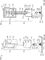
- FIGS. 1A and 1B illustrate an example thread alignment tool 100 constructed in accordance with the teachings of this disclosure.
- the example thread alignment tool 100 is part of a motorized wrench 103 that includes an example motor assembly 105.
- FIG. 1A is a perspective view of the example motorized wrench 103 and
- FIG. 1B is a cross-sectional view of the example motorized wrench 103 taken along line A-A in FIG. 1A .
- the example motorized wrench 103 can be used to align and couple a first threaded part and a second threaded part.
- an example fastener 102 and an example threaded pin 104 are illustrated in FIGS. 1A and 1B .
- the fastener 102 and the threaded pin 104 are to be threadably coupled to hold or secure a first part 106 and a second part 108 together.
- the threaded pin 104 is inserted through an opening 110 formed in the first and second parts 106, 108.
- a head 112 of the threaded pin 104 engages a bottom or backside of the second part 108 and an end 114 of the thread pin 104 extends outward through the opening 110 from first part 106.
- the fastener 102 includes a threaded opening 116 to receive the threaded pin 104.
- the fastener 102 is to be threadably coupled to the threaded pin 104 to hold the first and second parts 106, 108 between the fastener 102 and the head 112 of the threaded pin 104.
- the fastener 102 is implemented as a frangible collar fastener, which includes a threaded collar 118 (e.g., a bolt engaging portion) and a nut 120 (e.g., a wrenching element).
- the nut 120 is coupled to the collar 118 via a breakable connection 122, such that when a predetermined amount of torque is applied to the nut 120 (relative to the collar 118), the connection 122 breaks and the nut 120 detaches from the collar 118, thereby leaving the collar 118 threadably coupled to the threaded pin 104.
- the opening 116 through the nut 120 is not threaded, such that the nut 120 does not connect to the threaded pin 104.
- the fastener 102 may be implemented as any other type of fastener, such as a standard hex nut, a wing nut, a flange nut, an acorn nut, a nylon insert lock nut, etc.
- the example thread alignment tool 100 includes a socket 124 (e.g., a head, a bit, etc.) to receive and hold the fastener 102.
- the shape of the socket 124 corresponds to the shape of the fastener 102 and, in particular, the shape of the nut 120 (e.g., a hexagon). In other examples, the socket 124 may have another shape depending on the shape of the corresponding fastener.
- the socket 124 is coupled to a driveshaft 126.
- the driveshaft 126 may be rotated (e.g., manually or via a motor) in one direction and/or the other to tighten or loosen the fastener 102 on the threaded pin 104.
- the driveshaft 126 is disposed within a shaft tube 128 (e.g., a bearing).
- the driveshaft 126 is rotatable within the shaft tube 128. Additionally, in some examples, the driveshaft 126 is also moveable in an axial direction through the shaft tube 128.
- one or more motors are provided to move the driveshaft 126.
- the motor assembly 105 includes a rotational motor 130 (e.g., a first motor, a rotary actuator) that rotates the driveshaft 126 and, thus, rotates the socket 124 and the fastener 102 when the fastener 102 is disposed in the socket 124.
- the rotational motor 130 is used to rotate the driveshaft 126 in a forward-thread direction to tighten the fastener 102 onto the threaded pin 104 and in a reverse-thread direction to loosen the fastener 102 from the threaded pin 104.
- the example motor assembly 105 includes an axial motor 132 (e.g., a second motor; a linear actuator) that moves the driveshaft 126 in an axial direction through the shaft tube 128.
- the rotational motor 130 and/or the axial motor 132 may be implemented as brushless direct-current (DC) servo motors, for example. In other examples, other types of motors may be used.
- the motor assembly 105 includes a motor housing 134 (e.g., a controller housing) that is coupled to the shaft tube 128 and contains the rotational motor 130 and the axial motor 132.
- the motorized wrench 103 includes an electronic control unit 136 that controls (e.g., actives or deactivates, changes the speed, changes the torque, changes the rotational direction, etc.) the rotational motor 130 and the axial motor 132.
- the thread alignment tool 100 includes a cup 138 (e.g., a damping shell) that forms a cavity 140 in which the socket 124 is disposed.
- the cup 138 is coupled to an end of the shaft tube 128 (opposite the motor housing 134).
- the driveshaft 126 extends through an opening 142 in the cup 138 and disposes the socket 124 in the cavity 140.
- the cup 138 helps isolate the acoustic waves inside the cup 138 while dampening or deadening external acoustic waves outside the cup 138, as disclosed in further detail herein. As illustrated in FIGS.
- a seal 144 is coupled to a rim 146 of the cup 138. Therefore, when the cup 138 is placed on the first part 106 around the threaded pin 104, a substantially acoustic-proof (e.g., sound-proof) cavity is formed around the fastener 102 and the threaded pin 104.
- the thread alignment tool 100 may be moved toward the first part 106 until the seal 144 and the rim 146 engage the first part 106, such that the threaded pin 104 is disposed within the cavity 140.
- the rotational and axial motors 130, 132 may be activated (individually or simultaneously) to move the fastener 102 toward the end 114 of the threaded pin 104 and/or rotate the fastener 102 relative to the threaded pin 104.
- the example thread alignment tool 100 includes a first sensor 148 that measures or detects acoustic waves or signal near the fastener 102 and the threaded pin 104.
- the first sensor 148 is implemented as an acoustic transducer (e.g., a microphone) that converts acoustic waves into an electrical signals that are analyzed by the electronic control unit 136.
- the example sensor 148 is used to detect a thread-fall acoustic signal generated by a thread-fall event between the fastener and the threaded pin.
- a thread-fall acoustic signal indicates the fastener 102 and the threaded pin 104 are aligned or substantially aligned and may be screwed together without the risk of cross-threading.
- the thread-fall acoustic signal may include one or more parts in any frequency, such as infrasound, sound (e.g., 20-20,000 hertz (Hz)), ultra-sound, etc.
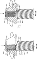
- FIG. 2A shows a partial cross-sectioned view of the example fastener 102 engaged with the end 114 of the threaded pin 104.
- the fastener 102 includes an internal thread 200 formed by a ridge 202 that is curved around an inner wall 204 of the opening 116.
- a start 206 of the ridge 202 is located at the bottom of the opening 116.
- the threaded pin 104 includes an external thread 208 formed by a ridge 210 that wraps around a body 212 of the threaded pin 104.
- a start 214 of the ridge 210 of the external thread 208 is located at or near the end 114 of the threaded pin 104.
- the fastener 102 is pressed (e.g., via the axial motor 132) downward onto the end 114 of the threaded pin 104 and rotated (e.g., via the rotational motor 130) in the reverse-thread direction (counter-clockwise looking down on the fastener 102).
- the fastener 102 is rotated, the first turn of the ridge 202 of the internal thread 200 slides against the first turn of the ridge 210 of the external thread 208.
- the fastener 102 and the threaded pin 104 are substantially axially aligned (e.g., ⁇ 0.5°)
- the fastener 102 drops or moves a small amount axially toward the threaded pin 104 when the start 206 of the ridge 202 of the internal thread 200 and the start 214 of the ridge 210 of the external thread 208 pass each other, as illustrated in FIG. 2B .
- the start 206 of the ridge 202 of the internal thread 200 falls into a groove 216 formed between the start 214 of the ridge 210 and the next turn of the ridge 210 of the external thread 208.
- the start 214 of the ridge 210 of the external thread 208 moves into a groove 218 formed between the start 206 of the ridge 202 and the next turn of the ridge 202 of the internal thread 200.
- This drop or movement creates a thread-fall acoustic signal, which can be detected by the first sensor 148 ( FIGS. 1A and 1B ).
- the drop in the thread-fall event only occurs when the fastener 102 and the threaded pin 104 are axially aligned or substantially axially aligned. Every time the fastener 102 and/or the threaded pin 104 are rotated 360°, a thread-fall event occurs (if the fastener 102 and the threaded pin 104 are substantially aligned).
- This acoustic event indicates that the fastener 102 and the threaded pin 104 are substantially axially aligned and that the starts 206, 214 of the threads 200, 208 are at the beginning of the corresponding grooves 216, 218. Otherwise, if the fastener 102 and the threaded pin 104 were not substantially axially aligned, the threads 200, 208 would continually ride along each other and no thread-fall event would occur and, thus, no thread-fall acoustic signal would be generated.
- the lack of a thread-fall event means that the fastener 102 and the threaded pin 104 are misaligned and should be aligned before tightening. Otherwise, if the fastener 102 and the threaded pin 104 are substantially aligned and a thread-fall event occurs, the starts 206, 214 of the ridges 210, 202 are in the corresponding grooves 216, 218, and the likelihood of cross-threading the fastener 102 and threaded pin 20 is significantly reduced (if not completely eliminated). As such, the fastener 102 can then be rotated in the forward-thread direction to tighten the fastener 102 onto the threaded pin 104 without the risk of cross-threading the two parts.
- the first sensor 148 measures the acoustic waves in the cup 138 while the fastener 102 is rotated in the reverse-thread direction against the end 114 of the threaded pin 104.
- the first sensor 148 is coupled to the cup 138 adjacent the socket 124.
- the first sensor 148 is communicatively coupled to the electronic control unit 136 via a wire 149 ( FIG. 1B ) embedded in the cup 138 and the shaft tube 128.
- the electronic control unit 136 determines the fastener 102 and the threaded pin 104 are aligned.
- the electronic control unit 136 stops the rotational motor 130 once the thread-fall acoustic signal is detected. Then, the electronic control unit 136 may activate the rotational motor 130 to rotate the driveshaft 126 in the forward-thread direction, thereby screwing or threading the fastener 102 onto the threaded pin 104. In some examples, the rotational motor 130 is activated to rotate the fastener 102 in the forward-thread direction until the nut 120 separates from the collar 118. Additionally or alternatively, the electronic control unit 136 may control the rotational motor 130 to apply a predetermined torque to the fastener 102 and/or rotate the fastener 102 a predetermined number of turns (e.g., 5 turns).
- a predetermined torque e.g., 5 turns
- the electronic control unit 136 activates (e.g., via a control signal) an indicator 150 ( FIGS. 1A and 1B ).
- the indicator 150 is implemented as a light disposed on the motor housing 134.
- the indicator 150 may be an alarm, an icon on a display screen (e.g., a display screen on the motor housing 134, a display on a handheld device such as a phone, a tablet, etc.), and/or any other audio or visual signal to indicate that the fastener 102 and the threaded pin 104 are aligned.
- the motorized wrench 103 includes an activation button 152 (e.g., a trigger), which may trigger the motor assembly 105 and/or the thread alignment tool 100 to perform one or more operations to align and/or couple the fastener 102 to the threaded pin 104 (e.g., the operations disclosed in connection with FIGS. 3A-3E ).
- an activation button 152 e.g., a trigger
- a user may load the fastener 102 into the socket 125 and place the cup 138 over the threaded pin 104.
- the nut 120 of the fastener 102 is held in the socket 124 via interference fit.
- a magnet or a retaining element may be used.
- the user may then press the activation button 152, which causes the electronic control unit 136 to activate the axial motor 132 to push the fastener 102 against the end 114 of the threaded pin 104 and activate the rotational motor 130 to rotate the fastener 102 in the reverse-thread direction.
- the electronic control unit 136 detects a thread-fall event (based on a thread-fall acoustic signal measured by the first sensor 148)
- the electronic control unit 136 stops the rotational motor 130 and then activates the rotational motor 130 to rotate the fastener 102 in the forward thread direction to tighten the fastener 102 onto the threaded pin 104.
- the activation button 152 causes the thread alignment tool 100 to align and couple the fastener 102 to the threaded pin 104.
- a user e.g., a worker or technician
- the motorized wrench 103 may be used to determine whether the fastener 102 and the threaded pin 104 are aligned (e.g., via the indicator 150). Then, the user may remove the motorized wrench 103 and use another device (e.g., a power tool or hand tool) to tighten the fastener 102 onto the threaded pin 104.
- the rotational motor 130 when rotating the fastener 102 in the reverse-thread direction, rotates the driveshaft 126 at a first speed, and when rotating the fastener 102 in the forward-thread direction, the rotational motor 130 rotates the driveshaft 126 at a second speed greater than the first speed.
- the fastener 102 when aligning the fastener 102 and the threaded pin 104, the fastener 102 is rotated at a slower speed. Then, once aligned, the fastener 102 can be rotated at a relatively fast speed in the forward-thread direction to tighten the fastener 102 onto the threaded pin 104.
- the speeds may be the same.
- the example thread alignment tool 100 includes a second sensor 154 (e.g., an acoustic transducer).
- the second sensor 154 is also coupled to the cup 138 to measure acoustic waves within the cavity 140.
- the second sensor 154 is communicatively coupled to the electronic control unit 136 via a wire embedded in the cup 138 and/or the shaft tube 126 (e.g., similar to the wire 149).
- the first and second sensors 148, 154 are spaced apart and calibrated so that acoustic waves generated within the cavity 140 are in phase, whereas acoustic waves generated outside of the cup 138 are out of phase (e.g., by a microsecond or more).
- the electronic control unit 136 may include a signal analyzer (as disclosed in further detail herein) to identify and block (e.g., attenuate) undesired noise in the acoustic signals and, thus, assist in isolating thread-fall acoustic waves corresponding to a thread-fall event.
- a signal analyzer as disclosed in further detail herein
- only one sensor is implemented with the example thread alignment tool 100. In other examples, more than two sensors may be implemented.
- the cup 138 is constructed of and/or coated with a sound deadening or acoustic damping material, such as an asphaltic material, which helps isolate acoustic waves generated within the cavity 140 from undesired acoustic waves generated in the environment outside of the cavity 140.
- the seal 144 may be constructed of a rubber material (e.g., neoprene), a plastic material, a foam and/or any other type acoustic sealing material. The seal 144 forms intimate contact between the cup 138 and the surface of the first part 106 to block out ambient noise. As such, the cup 138 helps to reject undesired noise in the outside environment from being detected by the first and second sensor 148, 154, so that the first and second sensors 148, 154 can more accurately detect the thread-fall acoustic signal.
- a sound deadening or acoustic damping material such as an asphaltic material
- the cup 138 is generally shaped as a dome. However, in other examples, the cup 138 may be shaped differently. For example, the cup 138 may be cube shaped. Also, while in the illustrated example the cup 138 substantially covers the fastener 102 and the threaded pin 104 when placed on the first part 106, in other examples, the cup 138 may have one or more openings. Further, the example first and second sensors 148, 154 may be attached to another structure (e.g., a flange or bracket) inside the cup 138 to be disposed near the fastener 102.
- another structure e.g., a flange or bracket
- the electronic control unit 136 may be separate from the motor housing 134.
- the electronic control unit 136 may be implemented in a handheld device (e.g., a phone, a tablet, etc.).
- the electronic control unit 136 may communicate with the rotational and axial motors 130, 132, the sensors 148, 154, and/or the other component(s) of the motorized wrench 103 via any wired or wireless (e.g., Bluetooth®) communication device.
- a user may control and/or view data (e.g., the live acoustic signal, such as in FIG. 5 ) obtained by the rotational and axial motors 130, 132, the sensors 148, 154, etc. via the handheld device.
- FIGS. 3A-3E illustrate an example sequence of aligning and connecting the threaded fastener 102 and the thread pin 104 as performed using the example motorized wrench 103 of FIGS. 1A and 1B .
- a portion of the cup 138 has been removed to expose the components therein.
- the threaded pin 104 is inserted through the opening 110 in the first and second parts 106, 108 and the fastener 102 is inserted into the socket 124.
- motorized wrench 103 is moved toward the threaded pin 104 until the cup 138 engages the first part 106 around the threaded pin 104, as illustrated in FIG. 3B .
- the seal 144 engages the first part 106 around the thread pin 104.
- the motorized wrench 103 is moved via a user (e.g., via human interaction). Additionally or alternatively, the motorized wrench 103 may be carried by a motorized platform that moves the motorized wrench 103.
- the cup 138 forms a sound isolated cavity around the fastener 102 and the threaded pin 104.
- the driveshaft 126 is moved axially through the shaft tube 128 to move the fastener 102 toward the end 114 of the threaded pin 104.
- the driveshaft 126 is moved axially via the axial motor 132 ( FIG. 1B ).
- the electronic control unit 136 activates the rotational motor 130 ( FIG. 1B ) to rotate the driveshaft 126 in the reverse-thread direction. While the driveshaft 126 rotates, the axial motor 132 continues to apply pressure toward the threaded pin 104.
- the first and second sensors 148, 154 measure the acoustic waves in the cavity 140. If a thread-fall event occurs, a thread-fall acoustic signal is generated, which is measured by the first and second sensors 148, 154.
- the electronic control unit 136 ( FIG. 1B ) then stops the rotational motor 130 from rotating the driveshaft 126 in the reverse-thread direction and activates the rotational motor 130 to rotate the driveshaft 126 in the forward-thread direction (opposite the reverse-thread direction) to tighten the fastener 102 onto the threaded pin 104, as illustrated in FIG. 3D . When a sufficient amount of torque is applied to the nut 120 ( FIGS.
- the nut 120 separates from of the collar 118, thereby leaving the collar 118 attached to the threaded pin 104.
- the friction between the collar 118 and the first part 106 requires an increasing amount of torque to continue rotating the fastener 102.
- the torque applied to the nut 120 causes the nut 120 to separate from the collar 118 (e.g., via the breakable connection 122 ( FIGS. 1A and 1B )).
- the electronic control unit 136 stops the rotational motor 130 ( FIG. 1B ) once the nut 120 breaks away or separates from the collar 118.
- the electronic control unit 136 may control the rotational motor 130 to apply a predetermined amount of torque and/or rotate a predetermined number of turns before stopping.
- the driveshaft 126 may be moved axially away from the threaded pin 104 (e.g., via the axial motor 132), as illustrated in the example of FIG. 3E .
- the nut 120 may be removed from the socket 124 and the example sequence may be repeated again on another threaded pin with another fastener. As described herein, this example sequence can be repeated numerous times.
- the sequence of FIGS. 3A-3E is activated via the activation button 152.
- FIG. 4 is an example block representation of the example electronic control unit 136 implemented with the example thread alignment tool 100 as part of the example motorized wrench 103 ( FIGS. 1A and 1B ).
- the electronic control unit 136 includes an activation processor 400.
- the activation processor 400 may receive an input signal from the activation button 152 and activate the electronic control unit 136 to perform an alignment operation and/or tightening operation, such as the operation(s) disclosed in connection with FIGS. 3A-3E and/or the operation(s) disclosed in connection with the flowchart in FIG. 7 .
- the activation processor 400 may control the electronic control unit 136 to lower the driveshaft 126, rotate the driveshaft 126, monitor for a thread-fall acoustic signal, rotate the driveshaft 126 in the opposite direction, etc.
- the electronic control unit 136 includes a motor controller 402 to control the rotational motor 130 and the axial motor 132.
- the motor controller 402 may activate the rotational motor 130 (e.g., via a control signal) to rotate in one direction or the opposite direction and/or may activate the axial motor 132 to move the driveshaft 126 ( FIG. 1B ) up or down.
- the electronic control unit 136 includes a torque detector 404 to detect an amount of torque applied by the rotational motor 130 to the fastener 102 ( FIGS. 1A and 1B ).
- the rotational motor 130 may tighten the fastener 102 to a predetermined torque, as sensed by the torque detector 404.
- the fastener 102 is a frangible collar fastener, which has a nut or wrenching element that breaks away from a collar when a predetermined torque is applied.
- the torque detector 404 may detect a decrease in torque applied by the rotational motor 130, which indicates the wrenching element has detached and a predetermined torque has been reached.
- the motorized wrench 103 includes a battery 406 to provide power to the electronic control unit 136, the rotational and axial motors 130, 132, and/or any other component of the example thread alignment tool 100 and/or the motor assembly 105.
- the battery 406 is disposed in the motor casing 134 ( FIGS. 1A and 1B ). Additionally or alternatively, the motorized wrench 103 may receive power from a generator and/or power from a public and/or private power grid.
- the electronic control unit 136 includes a signal analyzer 408 that analyzes the acoustic signals (e.g., the acoustic signatures) from the first and/or second sensor(s) 148, 154 and determines whether a thread-fall event has occurred such as, for example, based on a detected thread-fall acoustic signal.
- the signal analyzer 408 activates the indicator 150 when a thread-fall acoustic signal is detected.
- the motor controller 402 may stop the rotational motor 130 and/or activate the rotational motor 130 to rotate in the opposite direction (the forward-thread direction).
- the signal analyzer 408 identifies a thread-fall acoustic signal based on a spike (e.g., a point of interest) in the level or amplitude of the acoustic signal.
- a spike e.g., a point of interest
- FIG. 5 shows an example graph 500 of an acoustic signal recorded while a fastener is rotated in a reverse-thread direction against an end of a threaded pin.
- the X-axis represents time in seconds and the Y-axis represents the amplitude of the acoustic signal in decibels.
- the fastener is rotated more than three times, each time generating a thread-fall event. As illustrated in FIG.
- a thread-fall event generates a noticeable acoustic effect
- a thread-fall acoustic signal (as compared to the baseline noise around 0 decibels (dB)), which indicates the fastener and the threaded pin are substantially axially aligned.
- the signal analyzer 408 of FIG. 4 identifies a spike (e.g., a point of interest) in the acoustic signal as being a thread-fall acoustic signal when the spike exceeds an amplitude threshold (e.g., 50dB).
- the amplitude threshold may be based on, for example, on one or more of the amount of downward pressure applied by the axial motor 132, the type of material of the fastener 102 and/or the threaded pin 104, the type of material of the first and/or second parts 106, 108, the size of the fastener 102 and/or the threaded pin 104, and/or the speed at which the fastener 102 is rotated.
- a plurality of different amplitude thresholds are stored in the database 410. For example, a number of calibration tests may be performed using the example thread alignment tool 100 with different combinations of materials, pressure, etc., to determine the amplitude at which the thread-fall acoustic signals are generated.
- the signal analyzer 408 may monitor for a spike in amplitude occurring at a certain frequency or in a frequency range (e.g., 1300-1800Hz).
- the frequency or frequency range may be audible or inaudible to a human.
- a number of calibration tests may be performed using different combinations of material(s), pressure, etc. to determine a frequency range at which the thread-fall acoustic signal is generated.
- the signal analyzer 408 may then isolate a particular frequency range in the acoustic signal and determine whether a thread-fall acoustic signal has occurred based on an increase or spike in the isolated frequency range.
- the acoustic signals are compared to one or more reference signals stored in a database 410 to determine whether a thread-fall acoustic signal has occurred.
- the database 410 may include a plurality of reference thread-fall acoustic signatures, which can be compared to the current acoustic signal to determine if any similar acoustic signatures have occurred.
- the signal analyzer 408 filters or blocks out ambient noise from the surrounding environment.
- the signal analyzer 408 may analyze the acoustic signals from the first and second sensors 148, 154 and determine whether the acoustic signals are within phase or out of phase. Acoustic signals that are out of phase may be blocked, for example.
- the signal analyzer 408 may include one or more filters to filter out noise above and/or below a certain frequency (e.g., using a band-pass filter, a low-pass filter and/or a high-pass filter).
- the thread alignment tool 100 may be used in an environment with percussive operations such as riveting or hammering.
- the example signal analyzer 408 may filter out the acoustic waves or signals at particular frequencies (or a range of frequencies) corresponding to those percussive operations. In some examples, if the ambient acoustic signal contains a range of signals (e.g., sound) in the region of interest without actuation of the rotational motor 130 and/or the axial motor 132, the example electronic control unit 136 may wait until the ambient acoustic signals cease prior to starting the thread fall detection operation.
- a range of signals e.g., sound
- FIG. 6 illustrates an example of the thread alignment tool 100 without the motor assembly 105 as utilized in the example of FIGS. 1A and 1B . Instead, a user may use his/her hands, a hand-tool such as a wrench and/or a power tool such as a pneumatic or electric wrench to rotate and/or axially move the driveshaft 126.
- a hand-tool such as a wrench and/or a power tool such as a pneumatic or electric wrench to rotate and/or axially move the driveshaft 126.
- an example wrench 600 is depicted.
- a user may connect the wrench 600 to the driveshaft 126 and push the driveshaft 126 through the shaft tube 128 to engage the fastener 102 with the end 114 of the threaded pin 104.
- the user may then rotate the driveshaft 126 (via the wrench 600) to turn the fastener 102 in the reverse-threaded direction.
- the first and second sensors 148, 154 measure the acoustic signals in the cavity 140.
- the signals are communicated to an electronic control unit 602 that includes the signal analyzer 408 and the database 410, which are disclosed in connection with FIG. 4 . To avoid redundancy, a description of the signal analyzer 408 and the database 410 are not repeated.
- the interested reader is referred back to the discussion of FIG. 4 for a description of the signal analyzer 408 and the database 410.
- the sensors 148, 154 are communicatively coupled to the electronic control unit 602 via wires 604. In others examples, the sensors 148, 154 may wirelessly communicate with the electronic control unit 136.
- the signal analyzer 408 may activate the indicator 150 (e.g., a light) to alert to the user that the threads are aligned.
- the electronic control unit 602 may be implemented in a handheld device, for example, such as a phone or a tablet, and the indicator 150 may be a light or signal on a display screen of the handheld device.
- the user may rotate the driveshaft 126 (via the wrench 600) in the opposite direction to turn the fastener 102 in the forward-thread direction to tighten the fastener 102 onto the threaded pin 104.
- the user may remove the thread alignment tool 100 (while leaving the fastener 102 on the end 114 of the threaded pin 104), and tighten the fastener 102 with a separate tool (e.g., a power tool).
- a separate tool e.g., a power tool.
- the example thread alignment tool 100 can be used to align and/or start a fastener before a motorized tool screws the fastener 102 onto the threaded pin 104.
- FIGS. 4 and 6 While example manners of implementing the electronic control units 136, 602 are illustrated in FIGS. 4 and 6 , one or more of the elements, processes and/or devices illustrated in FIGS. 4 and 6 may be combined, divided, re-arranged, omitted, eliminated and/or implemented in any other way. Further, the example activation processor 400, the example motor controller 402, the example torque detector 404, the example signal analyzer 408, the example database 410 and/or, more generally, the example electronic control unit 136 of FIG. 4 and/or the example electronic control unit 602 of FIG. 6 may be implemented by hardware, software, firmware and/or any combination of hardware, software and/or firmware.
- any of the example activation processor 400, the example motor controller 402, the example torque detector 404, the example signal analyzer 408, the example database 410 and/or, more generally, the example electronic control unit 136 of FIG. 4 and/or the example electronic control unit 602 of FIG. 6 could be implemented by one or more analog or digital circuit(s), logic circuits, programmable processor(s), application specific integrated circuit(s) (ASIC(s)), programmable logic device(s) (PLD(s)) and/or field programmable logic device(s) (FPLD(s)).
- ASIC application specific integrated circuit
- PLD programmable logic device
- FPLD field programmable logic device
- At least one of the example activation processor 400, the example motor controller 402, the example torque detector 404, the example signal analyzer 408, and/or the example database 410 is/are hereby expressly defined to include a tangible computer readable storage device or storage disk such as a memory, a digital versatile disk (DVD), a compact disk (CD), a Blu-ray disk, etc. storing the software and/or firmware.
- the example electronic control unit 136 of FIG. 4 and/or the electronic control unit 602 may include one or more elements, processes and/or devices in addition to, or instead of, those illustrated in FIGS. 4 and 6 , and/or may include more than one of any or all of the illustrated elements, processes and devices.
- FIG. 7 A flowchart representative of an example method for implementing the example electronic control unit 136 of FIG. 4 (and, at least in part by the example electronic control unit 602 of FIG. 6 ) is shown in FIG. 7 .
- the method may be implemented, at least in part, by machine readable instructions that comprise a program for execution by a processor such as the processor 812 shown in the example processor platform 800 discussed below in connection with FIG. 8 .
- the program may be embodied in software stored on a tangible computer readable storage medium such as a CD-ROM, a floppy disk, a hard drive, a digital versatile disk (DVD), a Blu-ray disk, or a memory associated with the processor 812, but the entire program and/or parts thereof could alternatively be executed by a device other than the processor 812 and/or embodied in firmware or dedicated hardware.
- a tangible computer readable storage medium such as a CD-ROM, a floppy disk, a hard drive, a digital versatile disk (DVD), a Blu-ray disk, or a memory associated with the processor 812, but the entire program and/or parts thereof could alternatively be executed by a device other than the processor 812 and/or embodied in firmware or dedicated hardware.
- a device such as a CD-ROM, a floppy disk, a hard drive, a digital versatile disk (DVD), a Blu-ray disk, or a memory associated with the processor 812
- DVD digital versatile disk
- the example method of FIG. 7 may be implemented using coded instructions (e.g., computer and/or machine readable instructions) stored on a tangible computer readable storage medium such as a hard disk drive, a flash memory, a read-only memory (ROM), a compact disk (CD), a digital versatile disk (DVD), a cache, a random-access memory (RAM) and/or any other storage device or storage disk in which information is stored for any duration (e.g., for extended time periods, permanently, for brief instances, for temporarily buffering, and/or for caching of the information).
- a tangible computer readable storage medium is expressly defined to include any type of computer readable storage device and/or storage disk and to exclude propagating signals and to exclude transmission media.
- tangible computer readable storage medium and “tangible machine readable storage medium” are used interchangeably. Additionally or alternatively, the example method of FIG. 7 may be implemented using coded instructions (e.g., computer and/or machine readable instructions) stored on a non-transitory computer and/or machine readable medium such as a hard disk drive, a flash memory, a read-only memory, a compact disk, a digital versatile disk, a cache, a random-access memory and/or any other storage device or storage disk in which information is stored for any duration (e.g., for extended time periods, permanently, for brief instances, for temporarily buffering, and/or for caching of the information).
- coded instructions e.g., computer and/or machine readable instructions
- a non-transitory computer and/or machine readable medium such as a hard disk drive, a flash memory, a read-only memory, a compact disk, a digital versatile disk, a cache, a random-access memory and/or any other storage device or storage disk in which information is
- non-transitory computer readable medium is expressly defined to include any type of computer readable storage device and/or storage disk and to exclude propagating signals and to exclude transmission media.
- phrase "at least" is used as the transition term in a preamble of a claim, it is open-ended in the same manner as the term “comprising" is open ended.
- FIG. 7 is a flowchart representative of an example method 700 to align and couple a fastener and a threaded pin using the example motorized wrench 103.
- the example method 700 may be performed at least in part by machine readable instructions as implemented by the example electronic control unit 136.
- the example method 700 is described in connection with the motorized wrench 103 illustrated in FIGS. 1A and 1B and in connection with the sequence illustrated in FIGS. 3A-3E .
- the threaded pin 104 is inserted through the opening 110 of the first and second parts 106, 108. In some examples, this process may be automated. Additionally, the fastener 102 is inserted into the socket 124 of the thread alignment tool 100 (e.g., as illustrated in FIG. 3A ), and the thread alignment tool 100 is placed over the threaded pin 104. For example, referring to FIG. 3B , the motorized wrench 103 is moved toward the threaded pin 104 until the cup 138 covers the threaded pin 104.
- the motor controller 402 activates the axial motor 132 to move the driveshaft 126 toward the threaded pin 104 (e.g., downward) until the fastener 102 makes contact with the end 114 of the threaded pin 104, as illustrated in FIG. 3B .
- the axial motor 132 continues to apply pressure on the fastener 102 against the threaded pin 104.
- the movement of the driveshaft 126 may be performed manually by a user with his/her hand and/or a hand tool (e.g., a wrench).
- the motor controller 402 activates the rotational motor 130 to rotate the driveshaft 126 (and, thus, the socket 124 and the fastener 102) in a reverse-thread direction while the fastener 102 is pressed against the end 114 of the threaded pin 104 (e.g., via force from the axial motor 132), as illustrated in FIG. 3C .
- the driveshaft 126 may be rotated manually by a user with his/her hand and/or a hand tool (e.g., a wrench).
- the signal analyzer 408 determines whether a thread-fall event has occurred.
- the acoustic waves produced in the cavity 140 of the cup 138 are detected by the first and second sensors 148, 154.
- a thread-fall acoustic signal is generated (e.g., as illustrated in FIG. 5 ).
- the signal analyzer 408 identifies a thread-fall acoustic signal in the acoustic waves detected by the sensor(s) 148, 154
- the signal analyzer 408 determines a thread-fall event has occurred. Otherwise, if no thread-fall acoustic signal is detected, the rotational motor 130 continues to rotate the driveshaft 126 (at block 706).
- the example signal analyzer 408 can determine whether the fastener 102 and the threaded pin 104 are aligned (based on the occurrence of a thread-fall acoustic signal) before screwing the fastener 102 onto the threaded pin 104. In some examples, when the signal analyzer 408 detects a thread-fall acoustic signal, the signal analyzer 408 activates the indicator 150 (e.g., via a control signal), to indicate to the user that the fastener 102 and the threaded pin 104 are aligned.
- the indicator 150 e.g., via a control signal
- the motor controller 402 stops (e.g., deactivates) the rotational motor 130 from rotating the driveshaft 126 in the reverse-thread direction (at block 710).
- the motor controller 402 activates the rotational motor 130 to rotate the driveshaft 126 (and, thus, the socket 124 and the fastener 102) in a forward-thread direction while the axial motor 132 applies pressure towards the threaded pin 104, as illustrated in FIG. 3D .
- the fastener 102 rotates, the fastener 102 is threaded onto the threaded pin 104.
- the motor controller 402 determines whether a predetermined torque has been reached.
- the rotational motor 130 operates to apply a predetermined torque to the fastener 102. Once the predetermined torque is reached (e.g., as determined by torque detector 404), the motor controller 402 stops (e.g., deactivates) the rotational motor 130 at block 716.
- the fastener 102 may be a frangible collar type fastener. In such an example, the nut 120 breaks away or separates from the collar 118 when a predetermined torque is reached.
- the motor controller 402 may control the the rotational motor 130 to rotate the driveshaft 126 a predetermined number of times (e.g., 5 turns) or operate for a period of time (e.g., 2 seconds).
- the rotational motor 130 continues to rotate the driveshaft 126 in the forward-thread direction (at block 712) until the predetermined torque is reached. Once the predetermined torque is reached, the motor controller 402 stops the rotational motor 130 at block 716 and the example method 700 ends at block 718. In some examples, blocks 704-716 may be performed once the activation button 152 is pressed.
- FIG. 8 is a block diagram of an example processor platform 800 capable of executing instructions to implement the method of FIG. 7 and the electronic control unit 136 of FIG. 4 and/or the electronic control unit 602 of FIG. 6 .
- the processor platform 800 can be, for example, a server, a personal computer, a mobile device (e.g., a cell phone, a smart phone, a tablet such as an iPadTM), or any other type of computing device.
- the processor platform 800 of the illustrated example includes a processor 812.
- the processor 812 of the illustrated example is hardware.
- the processor 812 can be implemented by one or more integrated circuits, logic circuits, microprocessors or controllers from any desired family or manufacturer.
- the processor 812 may implement the example activation processor 400, the example motor controller 402, the example torque detector 404 and/or the example signal analyzer 408.
- the processor 812 of the illustrated example includes a local memory 813 (e.g., a cache).
- the processor 812 of the illustrated example is in communication with a main memory including a volatile memory 814 and a non-volatile memory 816 via a bus 818.
- the volatile memory 814 may be implemented by Synchronous Dynamic Random Access Memory (SDRAM), Dynamic Random Access Memory (DRAM), RAMBUS Dynamic Random Access Memory (RDRAM) and/or any other type of random access memory device.
- the non-volatile memory 816 may be implemented by flash memory and/or any other desired type of memory device. Access to the main memory 814, 816 is controlled by a memory controller.
- the processor platform 800 of the illustrated example also includes an interface circuit 820.
- the interface circuit 820 may be implemented by any type of interface standard, such as an Ethernet interface, a universal serial bus (USB), and/or a PCI express interface.
- one or more input devices 822 are connected to the interface circuit 820.
- the input device(s) 822 permit(s) a user to enter data and commands into the processor 812.
- the input device(s) can be implemented by, for example, an audio sensor, a microphone, a camera (still or video), a keyboard, a button, a mouse, a touchscreen, a track-pad, a trackball, isopoint and/or a voice recognition system.
- the input device(s) 822 may include one or both of the example sensor(s) 148, 154 and/or the activation button 152.
- One or more output devices 824 are also connected to the interface circuit 820 of the illustrated example.
- the output devices 824 can be implemented, for example, by display devices (e.g., a light emitting diode (LED), an organic light emitting diode (OLED), a liquid crystal display, a cathode ray tube display (CRT), a touchscreen, a tactile output device, a printer and/or speakers).
- the interface circuit 820 of the illustrated example thus, typically includes a graphics driver card, a graphics driver chip or a graphics driver processor.
- the output device(s) 824 may include the rotational motor 130, the axial motor 132 and/or the indicator 150.
- the interface circuit 820 of the illustrated example also includes a communication device such as a transmitter, a receiver, a transceiver, a modem and/or network interface card to facilitate exchange of data with external machines (e.g., computing devices of any kind) via a network 826 (e.g., an Ethernet connection, a digital subscriber line (DSL), a telephone line, coaxial cable, a cellular telephone system, etc.).
- a communication device such as a transmitter, a receiver, a transceiver, a modem and/or network interface card to facilitate exchange of data with external machines (e.g., computing devices of any kind) via a network 826 (e.g., an Ethernet connection, a digital subscriber line (DSL), a telephone line, coaxial cable, a cellular telephone system, etc.).
- DSL digital subscriber line
- the processor platform 800 of the illustrated example also includes one or more mass storage device(s) 828 for storing software and/or data.
- mass storage device(s) 828 include floppy disk drives, hard drive disks, compact disk drives, Blu-ray disk drives, RAID systems, and digital versatile disk (DVD) drives.
- the mass storage device(s) 828 may implement the example database 410.
- Coded instructions 832 to implement the method 700 of FIG. 7 may be stored in the mass storage device 828, in the volatile memory 814, in the non-volatile memory 816, and/or on a removable tangible computer readable storage medium such as a CD or DVD.
- examples disclosed herein leverage the acoustic signal generated when two threaded parts come into alignment while rotating one or both of the parts in the reverse-thread direction.
- examples disclosed herein utilize active feedback from an acoustic transducer to determine when the two threaded parts are aligned.
- the examples disclosed herein greatly reduce and/or eliminate the risk of cross-threading the two parts and, thus, enable proper threading of two parts. Further, examples disclosed herein also improve the speed of fastener installation.
- the examples illustrated herein move the female part (e.g., a nut) toward the male part (e.g., a bolt), the examples disclosed herein may likewise operate by moving the male part toward to the female part.
- the example thread alignment tool instead of holding the fastener, can hold the threaded pin, and can press the threaded pin against the fastener (which may be held stationary).
Landscapes
- Engineering & Computer Science (AREA)
- Mechanical Engineering (AREA)
- Physics & Mathematics (AREA)
- General Physics & Mathematics (AREA)
- Details Of Spanners, Wrenches, And Screw Drivers And Accessories (AREA)
- Investigating Or Analyzing Materials By The Use Of Ultrasonic Waves (AREA)
Claims (15)
- Dispositif comprenant :une douille (124) pour retenir un élément de fixation (102) ;une cuvette (38) définissant une cavité (140), la douille (124) étant disposée dans la cavité (140) ;un capteur (148, 154) disposé de manière adjacente à la douille (124), le capteur (148, 154) étant destiné à mesurer des ondes acoustiques à côté de la douille (124) tandis que la douille (124) fait tourner l'élément de fixation (102) dans une direction inverse au filet contre une extrémité d'une goupille filetée (104) ; etune unité de commande électronique (136) pour déterminer si l'élément de fixation (102) et la goupille filetée (104) sont alignés sur la base des ondes acoustiques mesurées par le capteur (148, 154).
- Dispositif selon la revendication 1, dans lequel l'unité de commande électronique (136) est destinée à déterminer que l'élément de fixation (102) et la goupille filetée (104) sont alignés lorsqu'un événement acoustique de chute de filet est détecté ; et comportant en outre en option un arbre d'entraînement (126) couplé à la douille (124).
- Dispositif selon la revendication 2, comportant en outre un arbre d'entraînement (126) couplé à la douille (124), et un moteur (130) pour faire tourner l'arbre d'entraînement (126), dans lequel l'unité de commande électronique (136) est destinée à activer le moteur (130) pour faire tourner l'arbre d'entraînement (126) et la douille (124) dans la direction inverse au filet jusqu'à ce que l'événement acoustique de chute de filet soit détecté.
- Dispositif selon la revendication 3, dans lequel l'unité de commande électronique (136) est destinée à activer le moteur (130) pour faire tourner l'arbre d'entraînement (126) et la douille (124) dans une direction vers l'avant du filet pour resserrer l'élément de fixation (102) sur la goupille filetée (104) après que l'événement acoustique de chute de filet soit détecté ; ou
dans lequel le moteur (130) est un premier moteur (130), le dispositif comportant en outre un second moteur (132) pour déplacer l'arbre d'entraînement (126) dans une direction axiale, l'unité de commande électronique (136) étant destinée à activer le second moteur (132) pour déplacer l'arbre d'entraînement (126) afin de presser l'élément de fixation (102) contre l'extrémité (114) de la goupille filetée (104) tandis que le premier moteur (130) fait tourner l'arbre d'entraînement (126) et la douille (124) dans la direction inverse au filet. - Dispositif selon une quelconque des revendications 1 à 4, dans lequel le capteur (148, 154) est couplé à la cuvette (138) pour mesurer les ondes acoustiques à côté de la douille (124) ; et
le dispositif comportant en outre en option un joint d'étanchéité (144) couplé à un bord (146) de la cuvette (138). - Dispositif selon une quelconque des revendications 1 à 5, dans lequel le capteur (148, 154) est un premier capteur (148), comportant en outre un second capteur (154) pour mesurer les ondes acoustiques à côté de la douille (124), et dans lequel l'unité de commande électronique (136) est destinée à identifier et bloquer tout bruit non souhaité sur les ondes acoustiques détectées par les premier (148) et second (154) capteurs.
- Dispositif selon une quelconque des revendications 1 à 6, dans lequel l'élément de fixation (102) est un élément de fixation de collier cassable présentant un collier (118) et un écrou (120), l'écrou (120) étant destiné à se découpler du collier (118) lorsqu'un couple prédéterminé est appliqué à l'écrou.
- Procédé destiné à aligner un élément de fixation (102) et une goupille filetée (104), le procédé comprenant les étapes consistant à :placer une cuvette (18) sur la goupille filetée pour former une cavité (140) sensiblement étanche acoustiquement autour de l'élément de fixation et de la goupille filetée ;faire tourner (706) un élément de fixation (102) contre une extrémité (114) de la goupille filetée (104) dans une direction inverse au filet ;détecter (708), avec un capteur (148, 154), un signal acoustique de chute de filet généré par l'élément de fixation (102) et la goupille filetée (104) ; etarrêter (710) la rotation dans la direction inverse au filet lorsque le signal acoustique de chute de filet est détecté.
- Procédé selon la revendication 8, comportant en outre les étapes consistant à faire tourner (712), après l'arrêt de la rotation dans la direction inverse au filet, l'élément de fixation fileté (102) dans une direction vers l'avant du filet.
- Procédé selon la revendication 9, dans lequel la rotation (706) de l'élément de fixation fileté (102) dans la direction inverse au filet comporte l'étape consistant à activer un moteur (130) pour faire tourner une douille (124) dans une première direction, la douille (124) retenant l'élément de fixation fileté (102),
dans lequel la rotation (712) de l'élément de fixation fileté (102) dans la direction vers l'avant du filet comporte en option l'étape consistant à activer le moteur (130) pour faire tourner la douille (124) dans une seconde direction opposée à la première direction. - Procédé selon la revendication 9 ou la revendication 10, comportant en outre l'étape consistant à faire tourner l'élément de fixation fileté (102) dans la direction vers l'avant du filet jusqu'à ce qu'un couple prédéterminé soit appliqué.
- Procédé selon une quelconque des revendications 8 à 11, comportant en outre l'étape consistant à activer un indicateur (150) lorsque le signal acoustique de chute de filet est détecté.
- Support de stockage lisible par une machine comprenant des instructions (832) qui, lorsqu'elles sont exécutées, amènent une machine à aligner un élément de fixation (102) et une goupille filetée (104), dans lequel les instructions, lorsqu'elles sont exécutées, amènent la machine au moins à :placer une cuvette (138) sur la goupille filetée pour former une cavité (140) sensiblement étanche acoustiquement autour de l'élément de fixation et de la goupille filetée ;faire tourner (706) un élément de fixation (102) contre une extrémité (114) de la goupille filetée (104) dans une direction inverse au filet ; etdéterminer (708) lorsque l'élément de fixation (102) et la goupille filetée (104) sont alignés sur la base d'un signal acoustique de chute de filet détecté par un capteur (148, 154) disposé à côté de l'élément de fixation (102).
- Support de stockage lisible par une machine selon la revendication 13, dans lequel les instructions (832), lorsqu'elles sont exécutées, amènent en outre la machine à arrêter (710) la rotation de l'élément de fixation (102) lorsque le signal acoustique de chute de filet est détecté.
- Support de stockage lisible par une machine selon la revendication 13 ou la revendication 14, dans lequel les instructions (832), lorsqu'elles sont exécutées, amènent en outre la machine à activer un indicateur (150) lorsque le signal acoustique de chute de filet est détecté.
Applications Claiming Priority (1)
| Application Number | Priority Date | Filing Date | Title |
|---|---|---|---|
| US15/415,521 US10399193B2 (en) | 2017-01-25 | 2017-01-25 | Methods and apparatus to align threaded fasteners |
Publications (2)
| Publication Number | Publication Date |
|---|---|
| EP3354397A1 EP3354397A1 (fr) | 2018-08-01 |
| EP3354397B1 true EP3354397B1 (fr) | 2020-06-24 |
Family
ID=60954767
Family Applications (1)
| Application Number | Title | Priority Date | Filing Date |
|---|---|---|---|
| EP17209759.4A Active EP3354397B1 (fr) | 2017-01-25 | 2017-12-21 | Procédés et appareil pour aligner des éléments de fixation filetés |
Country Status (6)
| Country | Link |
|---|---|
| US (1) | US10399193B2 (fr) |
| EP (1) | EP3354397B1 (fr) |
| CN (1) | CN108340147B (fr) |
| BR (1) | BR102017027984B1 (fr) |
| CA (1) | CA2985918C (fr) |
| ES (1) | ES2822208T3 (fr) |
Families Citing this family (21)
| Publication number | Priority date | Publication date | Assignee | Title |
|---|---|---|---|---|
| CN109693103B (zh) * | 2019-03-01 | 2024-02-27 | 西格迈股份有限公司 | 底阀螺母定扭力锁紧设备及其使用方法 |
| JP6959951B2 (ja) * | 2019-03-07 | 2021-11-05 | 株式会社日立ビルシステム | ねじ締結作業管理システム、ねじ締結作業良否判定装置及びねじ締結作業良否判定方法 |
| CN109773473B (zh) * | 2019-03-29 | 2023-10-27 | 广西玉柴机器股份有限公司 | 一种快速拆装螺母的拆装装置 |
| JP7369007B2 (ja) * | 2019-10-28 | 2023-10-25 | 株式会社Fuji | 実装機及び実装方法 |
| CN111376039B (zh) * | 2020-04-09 | 2021-10-08 | 云南电网有限责任公司电力科学研究院 | 防震锤螺栓紧固装置 |
| TWM607734U (zh) * | 2020-05-29 | 2021-02-11 | 盟立自動化股份有限公司 | 拆裝設備 |
| DE102020207850B4 (de) | 2020-06-24 | 2025-10-16 | Deprag Schulz Gmbh U. Co. | Schraubvorrichtung sowie Verfahren zur automatischen Durchführung eines Schraubvorgangs |
| CN111822983B (zh) * | 2020-07-31 | 2024-12-13 | 中铁建电气化局集团第一工程有限公司 | 一种用于预配简统化腕臂的平斜腕臂装配设备 |
| CN111822981B (zh) * | 2020-07-31 | 2025-02-11 | 中铁建电气化局集团第一工程有限公司 | 一种简统化腕臂加工用平斜腕臂装配装置 |
| TW202300259A (zh) | 2021-03-04 | 2023-01-01 | 日商美克司股份有限公司 | 緊固工具 |
| JP7753645B2 (ja) * | 2021-03-04 | 2025-10-15 | マックス株式会社 | 締結工具 |
| DE102021110411A1 (de) * | 2021-04-23 | 2022-10-27 | HELLA GmbH & Co. KGaA | Verfahren zur Herstellung einer Schraubverbindung |
| US12240130B2 (en) | 2021-07-07 | 2025-03-04 | General Electric Company | System and method for automated movement of a robotic arm |
| CN113547482A (zh) * | 2021-07-27 | 2021-10-26 | 三门核电有限公司 | 一种长杆式自动紧固装置 |
| CN114670005A (zh) * | 2022-04-13 | 2022-06-28 | 上海船舶电子设备研究所(中国船舶重工集团公司第七二六研究所) | 控制预紧力的换能器阵元成型装置及操作方法 |
| CN115061352A (zh) * | 2022-05-30 | 2022-09-16 | 歌尔股份有限公司 | 一种巴管与中框连接结构的连接方法 |
| JP7579824B2 (ja) * | 2022-06-04 | 2024-11-08 | 了 久保田 | ねじ締め装置 |
| CN116197651B (zh) * | 2023-02-24 | 2025-08-12 | 宁波信泰机械有限公司 | 一种汽车摄像头组立位置校正机构 |
| WO2025074309A1 (fr) * | 2023-10-03 | 2025-04-10 | LockDown Industries Limited | Verrou de fixation |
| JP2026061087A (ja) * | 2024-09-30 | 2026-04-09 | 株式会社日立製作所 | 解体装置および解体方法 |
| CN120734684B (zh) * | 2025-09-05 | 2025-11-18 | 沈阳华拓智联科技有限公司 | 一种航空发动机盲腔内部螺母送料装置及方法 |
Family Cites Families (12)
| Publication number | Priority date | Publication date | Assignee | Title |
|---|---|---|---|---|
| JPS4939035B1 (fr) * | 1970-11-24 | 1974-10-22 | ||
| US3849115A (en) * | 1972-03-24 | 1974-11-19 | Mcdowell Wellman Eng Co | Sintering process |
| JPH1058248A (ja) | 1996-08-22 | 1998-03-03 | Japan Steel Works Ltd:The | ボルト締め装置 |
| JP2001235379A (ja) | 2000-02-25 | 2001-08-31 | Toshiba Tungaloy Co Ltd | 超音波プローブの組み込まれた軸力計測用のソケット |
| DE102006048694A1 (de) | 2006-10-14 | 2008-04-17 | Siemens Vdo Mechatronic Gmbh & Co. Kg | Verfahren und Vorrichtung zum Herstellen einer Verschraubung |
| JP4924823B2 (ja) | 2007-05-29 | 2012-04-25 | トヨタ自動車株式会社 | ボルト又はナットの緩め方法及び装置 |
| DE102011053150B9 (de) | 2011-08-31 | 2014-03-27 | Björn Maile | System und Verfahren zur klemmkrafterzeugenden Verschraubung von Bauteilen |
| JP6270000B2 (ja) * | 2013-05-07 | 2018-01-31 | アトラス・コプコ・インダストリアル・テクニーク・アクチボラグ | 超音波通信用センサーユニット |
| CN203449239U (zh) * | 2013-08-19 | 2014-02-26 | 绵阳福德机器人有限责任公司 | 一种电能表开盖检定机构 |
| CN104515991A (zh) * | 2013-10-01 | 2015-04-15 | 西安天任软件科技有限责任公司 | 一种带信号处理装置的超声波传感器 |
| US20160082557A1 (en) | 2014-09-22 | 2016-03-24 | Kuka Systems Corporation North America | Robotic apparatus and process for the installation of collars and nuts onto fasteners |
| CN205900896U (zh) * | 2016-07-28 | 2017-01-18 | 中山市大行电子科技有限公司 | 一种屏蔽信号数据线插头 |
-
2017
- 2017-01-25 US US15/415,521 patent/US10399193B2/en active Active
- 2017-11-15 CA CA2985918A patent/CA2985918C/fr active Active
- 2017-12-21 ES ES17209759T patent/ES2822208T3/es active Active
- 2017-12-21 EP EP17209759.4A patent/EP3354397B1/fr active Active
- 2017-12-22 BR BR102017027984-7A patent/BR102017027984B1/pt active IP Right Grant
- 2017-12-29 CN CN201711468086.0A patent/CN108340147B/zh active Active
Non-Patent Citations (1)
| Title |
|---|
| None * |
Also Published As
| Publication number | Publication date |
|---|---|
| CA2985918C (fr) | 2022-11-08 |
| ES2822208T3 (es) | 2021-04-29 |
| BR102017027984B1 (pt) | 2023-11-07 |
| US10399193B2 (en) | 2019-09-03 |
| BR102017027984A2 (pt) | 2018-08-14 |
| CN108340147A (zh) | 2018-07-31 |
| EP3354397A1 (fr) | 2018-08-01 |
| US20180207759A1 (en) | 2018-07-26 |
| CA2985918A1 (fr) | 2018-07-25 |
| CN108340147B (zh) | 2021-08-17 |
Similar Documents
| Publication | Publication Date | Title |
|---|---|---|
| CA2985918C (fr) | Methodes et appareils d'alignement de fixations filetees | |
| US9233458B2 (en) | Installation method for an expansion anchor and impact screwdriver for installing an expansion anchor | |
| US11491617B2 (en) | Method for controlling an electric motor of a power tool | |
| US7624618B2 (en) | Device with a screw plug and a range of devices | |
| JP2011173233A (ja) | ネジ締付け診断装置及び電動ドライバ | |
| JP2016534891A (ja) | 手持ち又は準固定の機械工具又は作業工具 | |
| CN106457534A (zh) | 优化的胀栓安置方法 | |
| CN108071655B (zh) | 指示松退量的紧固件 | |
| JP2013106470A (ja) | モータの異常診断装置 | |
| JP2021503378A (ja) | 締結具が事前に締め付けられていたかどうかを検出する方法 | |
| JP6399710B2 (ja) | トルクインパルス発生装置の診断方法 | |
| CN110919577A (zh) | 管道部件的安装方法和装置 | |
| JP6287693B2 (ja) | 部材結合構造 | |
| JP4924823B2 (ja) | ボルト又はナットの緩め方法及び装置 | |
| CN108953321B (zh) | 螺纹紧固组件及螺纹紧固件的到位检测方法及系统 | |
| JP2021098267A (ja) | プロセスの不具合ケースが認識された機械的接合及び成形プロセスにおいて、連結部材、特にフロードリルねじを検出する方法 | |
| KR20160027456A (ko) | 음향감지센서를 구비한 전동렌치 및 이를 사용한 체결방법 | |
| JP2014117097A (ja) | ケーブル支持装置 | |
| JP2014214852A (ja) | 袋ナット及びそれを備えたねじ込み式アンカー | |
| JP4770846B2 (ja) | 油井管用カップリング取付装置 | |
| KR101550430B1 (ko) | 나사산 디버링 장치 | |
| CN111185936B (zh) | 弹簧平衡器装置及其分解方法 | |
| JP2015044271A (ja) | ボルトテンショナ | |
| JP5289533B2 (ja) | ボルト加工方法 | |
| JP3201320U (ja) | ケーブル支持装置 |
Legal Events
| Date | Code | Title | Description |
|---|---|---|---|
| PUAI | Public reference made under article 153(3) epc to a published international application that has entered the european phase |
Free format text: ORIGINAL CODE: 0009012 |
|
| STAA | Information on the status of an ep patent application or granted ep patent |
Free format text: STATUS: REQUEST FOR EXAMINATION WAS MADE |
|
| 17P | Request for examination filed |
Effective date: 20171221 |
|
| AK | Designated contracting states |
Kind code of ref document: A1 Designated state(s): AL AT BE BG CH CY CZ DE DK EE ES FI FR GB GR HR HU IE IS IT LI LT LU LV MC MK MT NL NO PL PT RO RS SE SI SK SM TR |
|
| AX | Request for extension of the european patent |
Extension state: BA ME |
|
| GRAP | Despatch of communication of intention to grant a patent |
Free format text: ORIGINAL CODE: EPIDOSNIGR1 |
|
| STAA | Information on the status of an ep patent application or granted ep patent |
Free format text: STATUS: GRANT OF PATENT IS INTENDED |
|
| RIC1 | Information provided on ipc code assigned before grant |
Ipc: B25B 23/14 20060101ALI20191218BHEP Ipc: B23P 19/10 20060101ALI20191218BHEP Ipc: G01B 17/00 20060101ALI20191218BHEP Ipc: B25B 21/00 20060101ALI20191218BHEP Ipc: B23P 19/06 20060101AFI20191218BHEP |
|
| INTG | Intention to grant announced |
Effective date: 20200115 |
|
| GRAS | Grant fee paid |
Free format text: ORIGINAL CODE: EPIDOSNIGR3 |
|
| GRAA | (expected) grant |
Free format text: ORIGINAL CODE: 0009210 |
|
| STAA | Information on the status of an ep patent application or granted ep patent |
Free format text: STATUS: THE PATENT HAS BEEN GRANTED |
|
| AK | Designated contracting states |
Kind code of ref document: B1 Designated state(s): AL AT BE BG CH CY CZ DE DK EE ES FI FR GB GR HR HU IE IS IT LI LT LU LV MC MK MT NL NO PL PT RO RS SE SI SK SM TR |
|
| REG | Reference to a national code |
Ref country code: GB Ref legal event code: FG4D |
|
| REG | Reference to a national code |
Ref country code: CH Ref legal event code: EP |
|
| REG | Reference to a national code |
Ref country code: AT Ref legal event code: REF Ref document number: 1283409 Country of ref document: AT Kind code of ref document: T Effective date: 20200715 |
|
| REG | Reference to a national code |
Ref country code: DE Ref legal event code: R096 Ref document number: 602017018627 Country of ref document: DE |
|
| REG | Reference to a national code |
Ref country code: IE Ref legal event code: FG4D |
|
| PG25 | Lapsed in a contracting state [announced via postgrant information from national office to epo] |
Ref country code: NO Free format text: LAPSE BECAUSE OF FAILURE TO SUBMIT A TRANSLATION OF THE DESCRIPTION OR TO PAY THE FEE WITHIN THE PRESCRIBED TIME-LIMIT Effective date: 20200924 Ref country code: GR Free format text: LAPSE BECAUSE OF FAILURE TO SUBMIT A TRANSLATION OF THE DESCRIPTION OR TO PAY THE FEE WITHIN THE PRESCRIBED TIME-LIMIT Effective date: 20200925 Ref country code: SE Free format text: LAPSE BECAUSE OF FAILURE TO SUBMIT A TRANSLATION OF THE DESCRIPTION OR TO PAY THE FEE WITHIN THE PRESCRIBED TIME-LIMIT Effective date: 20200624 Ref country code: LT Free format text: LAPSE BECAUSE OF FAILURE TO SUBMIT A TRANSLATION OF THE DESCRIPTION OR TO PAY THE FEE WITHIN THE PRESCRIBED TIME-LIMIT Effective date: 20200624 Ref country code: FI Free format text: LAPSE BECAUSE OF FAILURE TO SUBMIT A TRANSLATION OF THE DESCRIPTION OR TO PAY THE FEE WITHIN THE PRESCRIBED TIME-LIMIT Effective date: 20200624 |
|
| REG | Reference to a national code |
Ref country code: LT Ref legal event code: MG4D |
|
| PG25 | Lapsed in a contracting state [announced via postgrant information from national office to epo] |
Ref country code: BG Free format text: LAPSE BECAUSE OF FAILURE TO SUBMIT A TRANSLATION OF THE DESCRIPTION OR TO PAY THE FEE WITHIN THE PRESCRIBED TIME-LIMIT Effective date: 20200924 Ref country code: LV Free format text: LAPSE BECAUSE OF FAILURE TO SUBMIT A TRANSLATION OF THE DESCRIPTION OR TO PAY THE FEE WITHIN THE PRESCRIBED TIME-LIMIT Effective date: 20200624 Ref country code: RS Free format text: LAPSE BECAUSE OF FAILURE TO SUBMIT A TRANSLATION OF THE DESCRIPTION OR TO PAY THE FEE WITHIN THE PRESCRIBED TIME-LIMIT Effective date: 20200624 Ref country code: HR Free format text: LAPSE BECAUSE OF FAILURE TO SUBMIT A TRANSLATION OF THE DESCRIPTION OR TO PAY THE FEE WITHIN THE PRESCRIBED TIME-LIMIT Effective date: 20200624 |
|
| REG | Reference to a national code |
Ref country code: NL Ref legal event code: MP Effective date: 20200624 |
|
| REG | Reference to a national code |
Ref country code: AT Ref legal event code: MK05 Ref document number: 1283409 Country of ref document: AT Kind code of ref document: T Effective date: 20200624 |
|
| PG25 | Lapsed in a contracting state [announced via postgrant information from national office to epo] |
Ref country code: AL Free format text: LAPSE BECAUSE OF FAILURE TO SUBMIT A TRANSLATION OF THE DESCRIPTION OR TO PAY THE FEE WITHIN THE PRESCRIBED TIME-LIMIT Effective date: 20200624 Ref country code: NL Free format text: LAPSE BECAUSE OF FAILURE TO SUBMIT A TRANSLATION OF THE DESCRIPTION OR TO PAY THE FEE WITHIN THE PRESCRIBED TIME-LIMIT Effective date: 20200624 |
|
| PG25 | Lapsed in a contracting state [announced via postgrant information from national office to epo] |
Ref country code: CZ Free format text: LAPSE BECAUSE OF FAILURE TO SUBMIT A TRANSLATION OF THE DESCRIPTION OR TO PAY THE FEE WITHIN THE PRESCRIBED TIME-LIMIT Effective date: 20200624 Ref country code: AT Free format text: LAPSE BECAUSE OF FAILURE TO SUBMIT A TRANSLATION OF THE DESCRIPTION OR TO PAY THE FEE WITHIN THE PRESCRIBED TIME-LIMIT Effective date: 20200624 Ref country code: RO Free format text: LAPSE BECAUSE OF FAILURE TO SUBMIT A TRANSLATION OF THE DESCRIPTION OR TO PAY THE FEE WITHIN THE PRESCRIBED TIME-LIMIT Effective date: 20200624 Ref country code: EE Free format text: LAPSE BECAUSE OF FAILURE TO SUBMIT A TRANSLATION OF THE DESCRIPTION OR TO PAY THE FEE WITHIN THE PRESCRIBED TIME-LIMIT Effective date: 20200624 Ref country code: SM Free format text: LAPSE BECAUSE OF FAILURE TO SUBMIT A TRANSLATION OF THE DESCRIPTION OR TO PAY THE FEE WITHIN THE PRESCRIBED TIME-LIMIT Effective date: 20200624 Ref country code: PT Free format text: LAPSE BECAUSE OF FAILURE TO SUBMIT A TRANSLATION OF THE DESCRIPTION OR TO PAY THE FEE WITHIN THE PRESCRIBED TIME-LIMIT Effective date: 20201026 |
|
| PG25 | Lapsed in a contracting state [announced via postgrant information from national office to epo] |
Ref country code: IS Free format text: LAPSE BECAUSE OF FAILURE TO SUBMIT A TRANSLATION OF THE DESCRIPTION OR TO PAY THE FEE WITHIN THE PRESCRIBED TIME-LIMIT Effective date: 20201024 Ref country code: SK Free format text: LAPSE BECAUSE OF FAILURE TO SUBMIT A TRANSLATION OF THE DESCRIPTION OR TO PAY THE FEE WITHIN THE PRESCRIBED TIME-LIMIT Effective date: 20200624 Ref country code: PL Free format text: LAPSE BECAUSE OF FAILURE TO SUBMIT A TRANSLATION OF THE DESCRIPTION OR TO PAY THE FEE WITHIN THE PRESCRIBED TIME-LIMIT Effective date: 20200624 |
|
| REG | Reference to a national code |
Ref country code: DE Ref legal event code: R097 Ref document number: 602017018627 Country of ref document: DE |
|
| PG25 | Lapsed in a contracting state [announced via postgrant information from national office to epo] |
Ref country code: DK Free format text: LAPSE BECAUSE OF FAILURE TO SUBMIT A TRANSLATION OF THE DESCRIPTION OR TO PAY THE FEE WITHIN THE PRESCRIBED TIME-LIMIT Effective date: 20200624 |
|
| PLBE | No opposition filed within time limit |
Free format text: ORIGINAL CODE: 0009261 |
|
| STAA | Information on the status of an ep patent application or granted ep patent |
Free format text: STATUS: NO OPPOSITION FILED WITHIN TIME LIMIT |
|
| 26N | No opposition filed |
Effective date: 20210325 |
|
| REG | Reference to a national code |
Ref country code: CH Ref legal event code: PL |
|
| PG25 | Lapsed in a contracting state [announced via postgrant information from national office to epo] |
Ref country code: MC Free format text: LAPSE BECAUSE OF FAILURE TO SUBMIT A TRANSLATION OF THE DESCRIPTION OR TO PAY THE FEE WITHIN THE PRESCRIBED TIME-LIMIT Effective date: 20200624 Ref country code: SI Free format text: LAPSE BECAUSE OF FAILURE TO SUBMIT A TRANSLATION OF THE DESCRIPTION OR TO PAY THE FEE WITHIN THE PRESCRIBED TIME-LIMIT Effective date: 20200624 |
|
| REG | Reference to a national code |
Ref country code: BE Ref legal event code: MM Effective date: 20201231 |
|
| PG25 | Lapsed in a contracting state [announced via postgrant information from national office to epo] |
Ref country code: IE Free format text: LAPSE BECAUSE OF NON-PAYMENT OF DUE FEES Effective date: 20201221 Ref country code: LU Free format text: LAPSE BECAUSE OF NON-PAYMENT OF DUE FEES Effective date: 20201221 |
|
| PG25 | Lapsed in a contracting state [announced via postgrant information from national office to epo] |
Ref country code: CH Free format text: LAPSE BECAUSE OF NON-PAYMENT OF DUE FEES Effective date: 20201231 Ref country code: LI Free format text: LAPSE BECAUSE OF NON-PAYMENT OF DUE FEES Effective date: 20201231 |
|
| PG25 | Lapsed in a contracting state [announced via postgrant information from national office to epo] |
Ref country code: TR Free format text: LAPSE BECAUSE OF FAILURE TO SUBMIT A TRANSLATION OF THE DESCRIPTION OR TO PAY THE FEE WITHIN THE PRESCRIBED TIME-LIMIT Effective date: 20200624 Ref country code: MT Free format text: LAPSE BECAUSE OF FAILURE TO SUBMIT A TRANSLATION OF THE DESCRIPTION OR TO PAY THE FEE WITHIN THE PRESCRIBED TIME-LIMIT Effective date: 20200624 Ref country code: CY Free format text: LAPSE BECAUSE OF FAILURE TO SUBMIT A TRANSLATION OF THE DESCRIPTION OR TO PAY THE FEE WITHIN THE PRESCRIBED TIME-LIMIT Effective date: 20200624 |
|
| PG25 | Lapsed in a contracting state [announced via postgrant information from national office to epo] |
Ref country code: MK Free format text: LAPSE BECAUSE OF FAILURE TO SUBMIT A TRANSLATION OF THE DESCRIPTION OR TO PAY THE FEE WITHIN THE PRESCRIBED TIME-LIMIT Effective date: 20200624 |
|
| PG25 | Lapsed in a contracting state [announced via postgrant information from national office to epo] |
Ref country code: BE Free format text: LAPSE BECAUSE OF NON-PAYMENT OF DUE FEES Effective date: 20201231 |
|
| P01 | Opt-out of the competence of the unified patent court (upc) registered |
Effective date: 20230516 |
|
| PGFP | Annual fee paid to national office [announced via postgrant information from national office to epo] |
Ref country code: GB Payment date: 20251229 Year of fee payment: 9 |
|
| PGFP | Annual fee paid to national office [announced via postgrant information from national office to epo] |
Ref country code: IT Payment date: 20251219 Year of fee payment: 9 |
|
| PGFP | Annual fee paid to national office [announced via postgrant information from national office to epo] |
Ref country code: FR Payment date: 20251226 Year of fee payment: 9 |
|
| PGFP | Annual fee paid to national office [announced via postgrant information from national office to epo] |
Ref country code: ES Payment date: 20260102 Year of fee payment: 9 |
|
| PGFP | Annual fee paid to national office [announced via postgrant information from national office to epo] |
Ref country code: DE Payment date: 20251229 Year of fee payment: 9 |